EP3118179A1 - Coating system on a ceramic matrix composite substrate and method of deposition of a sacrificial coating on a ceramic matrix composite substrate - Google Patents
Coating system on a ceramic matrix composite substrate and method of deposition of a sacrificial coating on a ceramic matrix composite substrate Download PDFInfo
- Publication number
- EP3118179A1 EP3118179A1 EP16178851.8A EP16178851A EP3118179A1 EP 3118179 A1 EP3118179 A1 EP 3118179A1 EP 16178851 A EP16178851 A EP 16178851A EP 3118179 A1 EP3118179 A1 EP 3118179A1
- Authority
- EP
- European Patent Office
- Prior art keywords
- rare earth
- coating
- earth silicate
- mils
- sacrificial
- Prior art date
- Legal status (The legal status is an assumption and is not a legal conclusion. Google has not performed a legal analysis and makes no representation as to the accuracy of the status listed.)
- Withdrawn
Links
- 238000000576 coating method Methods 0.000 title claims abstract description 195
- 239000011248 coating agent Substances 0.000 title claims abstract description 193
- 239000000758 substrate Substances 0.000 title claims abstract description 32
- 238000000034 method Methods 0.000 title claims abstract description 21
- 230000008021 deposition Effects 0.000 title claims abstract description 10
- 239000011153 ceramic matrix composite Substances 0.000 title description 4
- 229910052761 rare earth metal Inorganic materials 0.000 claims abstract description 155
- -1 rare earth silicate Chemical class 0.000 claims abstract description 128
- 239000011159 matrix material Substances 0.000 claims abstract description 47
- 150000002910 rare earth metals Chemical class 0.000 claims description 27
- 239000000203 mixture Substances 0.000 claims description 16
- 238000005245 sintering Methods 0.000 claims description 13
- 239000011362 coarse particle Substances 0.000 claims description 9
- 238000001035 drying Methods 0.000 claims description 8
- 239000002904 solvent Substances 0.000 claims description 8
- 239000002245 particle Substances 0.000 claims description 6
- 239000000843 powder Substances 0.000 claims description 6
- XUIMIQQOPSSXEZ-UHFFFAOYSA-N Silicon Chemical compound [Si] XUIMIQQOPSSXEZ-UHFFFAOYSA-N 0.000 claims description 3
- 229910052710 silicon Inorganic materials 0.000 claims description 3
- 239000010703 silicon Substances 0.000 claims description 3
- WOIHABYNKOEWFG-UHFFFAOYSA-N [Sr].[Ba] Chemical compound [Sr].[Ba] WOIHABYNKOEWFG-UHFFFAOYSA-N 0.000 claims description 2
- 229910000323 aluminium silicate Inorganic materials 0.000 claims description 2
- HNPSIPDUKPIQMN-UHFFFAOYSA-N dioxosilane;oxo(oxoalumanyloxy)alumane Chemical compound O=[Si]=O.O=[Al]O[Al]=O HNPSIPDUKPIQMN-UHFFFAOYSA-N 0.000 claims description 2
- 239000002923 metal particle Substances 0.000 claims description 2
- 239000011856 silicon-based particle Substances 0.000 claims description 2
- 239000010410 layer Substances 0.000 description 47
- 238000000151 deposition Methods 0.000 description 13
- 239000002002 slurry Substances 0.000 description 11
- 239000007789 gas Substances 0.000 description 10
- 239000000463 material Substances 0.000 description 6
- PXHVJJICTQNCMI-UHFFFAOYSA-N Nickel Chemical compound [Ni] PXHVJJICTQNCMI-UHFFFAOYSA-N 0.000 description 4
- BPQQTUXANYXVAA-UHFFFAOYSA-N Orthosilicate Chemical compound [O-][Si]([O-])([O-])[O-] BPQQTUXANYXVAA-UHFFFAOYSA-N 0.000 description 4
- 230000008901 benefit Effects 0.000 description 3
- 239000008199 coating composition Substances 0.000 description 3
- 239000000567 combustion gas Substances 0.000 description 3
- 230000003647 oxidation Effects 0.000 description 3
- 238000007254 oxidation reaction Methods 0.000 description 3
- 239000000126 substance Substances 0.000 description 3
- 229910000601 superalloy Inorganic materials 0.000 description 3
- UIFCJGUHVSPNFF-UHFFFAOYSA-N trioxido(trioxidosilyloxy)silane ytterbium(3+) yttrium(3+) Chemical compound [Si]([O-])([O-])([O-])O[Si]([O-])([O-])[O-].[Y+3].[Yb+3] UIFCJGUHVSPNFF-UHFFFAOYSA-N 0.000 description 3
- 229910052691 Erbium Inorganic materials 0.000 description 2
- 229910052688 Gadolinium Inorganic materials 0.000 description 2
- 241000588731 Hafnia Species 0.000 description 2
- 229910052765 Lutetium Inorganic materials 0.000 description 2
- 229910052779 Neodymium Inorganic materials 0.000 description 2
- 229910052775 Thulium Inorganic materials 0.000 description 2
- MCMNRKCIXSYSNV-UHFFFAOYSA-N Zirconium dioxide Chemical compound O=[Zr]=O MCMNRKCIXSYSNV-UHFFFAOYSA-N 0.000 description 2
- 230000004888 barrier function Effects 0.000 description 2
- 239000011230 binding agent Substances 0.000 description 2
- DOIRQSBPFJWKBE-UHFFFAOYSA-N dibutyl phthalate Chemical compound CCCCOC(=O)C1=CC=CC=C1C(=O)OCCCC DOIRQSBPFJWKBE-UHFFFAOYSA-N 0.000 description 2
- 230000007613 environmental effect Effects 0.000 description 2
- UYAHIZSMUZPPFV-UHFFFAOYSA-N erbium Chemical compound [Er] UYAHIZSMUZPPFV-UHFFFAOYSA-N 0.000 description 2
- UIWYJDYFSGRHKR-UHFFFAOYSA-N gadolinium atom Chemical compound [Gd] UIWYJDYFSGRHKR-UHFFFAOYSA-N 0.000 description 2
- CJNBYAVZURUTKZ-UHFFFAOYSA-N hafnium(IV) oxide Inorganic materials O=[Hf]=O CJNBYAVZURUTKZ-UHFFFAOYSA-N 0.000 description 2
- 238000010438 heat treatment Methods 0.000 description 2
- OHSVLFRHMCKCQY-UHFFFAOYSA-N lutetium atom Chemical compound [Lu] OHSVLFRHMCKCQY-UHFFFAOYSA-N 0.000 description 2
- 229910052751 metal Inorganic materials 0.000 description 2
- 239000002184 metal Substances 0.000 description 2
- 238000012986 modification Methods 0.000 description 2
- 230000004048 modification Effects 0.000 description 2
- QEFYFXOXNSNQGX-UHFFFAOYSA-N neodymium atom Chemical compound [Nd] QEFYFXOXNSNQGX-UHFFFAOYSA-N 0.000 description 2
- 229910052759 nickel Inorganic materials 0.000 description 2
- 230000035515 penetration Effects 0.000 description 2
- 239000004014 plasticizer Substances 0.000 description 2
- 238000003825 pressing Methods 0.000 description 2
- 230000008569 process Effects 0.000 description 2
- 238000000926 separation method Methods 0.000 description 2
- 239000002356 single layer Substances 0.000 description 2
- 229910052727 yttrium Inorganic materials 0.000 description 2
- VWQVUPCCIRVNHF-UHFFFAOYSA-N yttrium atom Chemical compound [Y] VWQVUPCCIRVNHF-UHFFFAOYSA-N 0.000 description 2
- 229910052684 Cerium Inorganic materials 0.000 description 1
- 229910052692 Dysprosium Inorganic materials 0.000 description 1
- 229910052693 Europium Inorganic materials 0.000 description 1
- 229910052689 Holmium Inorganic materials 0.000 description 1
- UFHFLCQGNIYNRP-UHFFFAOYSA-N Hydrogen Chemical compound [H][H] UFHFLCQGNIYNRP-UHFFFAOYSA-N 0.000 description 1
- 229910052777 Praseodymium Inorganic materials 0.000 description 1
- 229910052773 Promethium Inorganic materials 0.000 description 1
- 229910052772 Samarium Inorganic materials 0.000 description 1
- 229910052771 Terbium Inorganic materials 0.000 description 1
- 229910003079 TiO5 Inorganic materials 0.000 description 1
- 229910052769 Ytterbium Inorganic materials 0.000 description 1
- XEDZPTDJMMNSIB-UHFFFAOYSA-N [Si]([O-])([O-])([O-])O.[Y+3] Chemical compound [Si]([O-])([O-])([O-])O.[Y+3] XEDZPTDJMMNSIB-UHFFFAOYSA-N 0.000 description 1
- 230000002411 adverse Effects 0.000 description 1
- 238000004873 anchoring Methods 0.000 description 1
- 230000015572 biosynthetic process Effects 0.000 description 1
- 239000000919 ceramic Substances 0.000 description 1
- 229910010293 ceramic material Inorganic materials 0.000 description 1
- GWXLDORMOJMVQZ-UHFFFAOYSA-N cerium Chemical compound [Ce] GWXLDORMOJMVQZ-UHFFFAOYSA-N 0.000 description 1
- 229910052729 chemical element Inorganic materials 0.000 description 1
- 238000002485 combustion reaction Methods 0.000 description 1
- 230000000295 complement effect Effects 0.000 description 1
- 239000000470 constituent Substances 0.000 description 1
- 239000000356 contaminant Substances 0.000 description 1
- 230000007547 defect Effects 0.000 description 1
- 238000000280 densification Methods 0.000 description 1
- 238000005137 deposition process Methods 0.000 description 1
- 239000000428 dust Substances 0.000 description 1
- KBQHZAAAGSGFKK-UHFFFAOYSA-N dysprosium atom Chemical compound [Dy] KBQHZAAAGSGFKK-UHFFFAOYSA-N 0.000 description 1
- 230000000694 effects Effects 0.000 description 1
- OGPBJKLSAFTDLK-UHFFFAOYSA-N europium atom Chemical compound [Eu] OGPBJKLSAFTDLK-UHFFFAOYSA-N 0.000 description 1
- 239000000446 fuel Substances 0.000 description 1
- 239000001307 helium Substances 0.000 description 1
- 229910052734 helium Inorganic materials 0.000 description 1
- SWQJXJOGLNCZEY-UHFFFAOYSA-N helium atom Chemical compound [He] SWQJXJOGLNCZEY-UHFFFAOYSA-N 0.000 description 1
- KJZYNXUDTRRSPN-UHFFFAOYSA-N holmium atom Chemical compound [Ho] KJZYNXUDTRRSPN-UHFFFAOYSA-N 0.000 description 1
- 239000001257 hydrogen Substances 0.000 description 1
- 229910052739 hydrogen Inorganic materials 0.000 description 1
- 230000003993 interaction Effects 0.000 description 1
- 229910052746 lanthanum Inorganic materials 0.000 description 1
- FZLIPJUXYLNCLC-UHFFFAOYSA-N lanthanum atom Chemical compound [La] FZLIPJUXYLNCLC-UHFFFAOYSA-N 0.000 description 1
- 238000011068 loading method Methods 0.000 description 1
- 238000002156 mixing Methods 0.000 description 1
- 230000000737 periodic effect Effects 0.000 description 1
- 229920002037 poly(vinyl butyral) polymer Polymers 0.000 description 1
- PUDIUYLPXJFUGB-UHFFFAOYSA-N praseodymium atom Chemical compound [Pr] PUDIUYLPXJFUGB-UHFFFAOYSA-N 0.000 description 1
- VQMWBBYLQSCNPO-UHFFFAOYSA-N promethium atom Chemical compound [Pm] VQMWBBYLQSCNPO-UHFFFAOYSA-N 0.000 description 1
- KZUNJOHGWZRPMI-UHFFFAOYSA-N samarium atom Chemical compound [Sm] KZUNJOHGWZRPMI-UHFFFAOYSA-N 0.000 description 1
- 229910052706 scandium Inorganic materials 0.000 description 1
- SIXSYDAISGFNSX-UHFFFAOYSA-N scandium atom Chemical compound [Sc] SIXSYDAISGFNSX-UHFFFAOYSA-N 0.000 description 1
- 239000007921 spray Substances 0.000 description 1
- 229910002076 stabilized zirconia Inorganic materials 0.000 description 1
- GZCRRIHWUXGPOV-UHFFFAOYSA-N terbium atom Chemical compound [Tb] GZCRRIHWUXGPOV-UHFFFAOYSA-N 0.000 description 1
- PZTAGFCBNDBBFZ-UHFFFAOYSA-N tert-butyl 2-(hydroxymethyl)piperidine-1-carboxylate Chemical compound CC(C)(C)OC(=O)N1CCCCC1CO PZTAGFCBNDBBFZ-UHFFFAOYSA-N 0.000 description 1
- FRNOGLGSGLTDKL-UHFFFAOYSA-N thulium atom Chemical compound [Tm] FRNOGLGSGLTDKL-UHFFFAOYSA-N 0.000 description 1
- NAWDYIZEMPQZHO-UHFFFAOYSA-N ytterbium Chemical compound [Yb] NAWDYIZEMPQZHO-UHFFFAOYSA-N 0.000 description 1
Images

Classifications
-
- C—CHEMISTRY; METALLURGY
- C04—CEMENTS; CONCRETE; ARTIFICIAL STONE; CERAMICS; REFRACTORIES
- C04B—LIME, MAGNESIA; SLAG; CEMENTS; COMPOSITIONS THEREOF, e.g. MORTARS, CONCRETE OR LIKE BUILDING MATERIALS; ARTIFICIAL STONE; CERAMICS; REFRACTORIES; TREATMENT OF NATURAL STONE
- C04B41/00—After-treatment of mortars, concrete, artificial stone or ceramics; Treatment of natural stone
- C04B41/45—Coating or impregnating, e.g. injection in masonry, partial coating of green or fired ceramics, organic coating compositions for adhering together two concrete elements
- C04B41/52—Multiple coating or impregnating multiple coating or impregnating with the same composition or with compositions only differing in the concentration of the constituents, is classified as single coating or impregnation
-
- F—MECHANICAL ENGINEERING; LIGHTING; HEATING; WEAPONS; BLASTING
- F01—MACHINES OR ENGINES IN GENERAL; ENGINE PLANTS IN GENERAL; STEAM ENGINES
- F01D—NON-POSITIVE DISPLACEMENT MACHINES OR ENGINES, e.g. STEAM TURBINES
- F01D5/00—Blades; Blade-carrying members; Heating, heat-insulating, cooling or antivibration means on the blades or the members
- F01D5/12—Blades
- F01D5/28—Selecting particular materials; Particular measures relating thereto; Measures against erosion or corrosion
- F01D5/288—Protective coatings for blades
-
- B—PERFORMING OPERATIONS; TRANSPORTING
- B32—LAYERED PRODUCTS
- B32B—LAYERED PRODUCTS, i.e. PRODUCTS BUILT-UP OF STRATA OF FLAT OR NON-FLAT, e.g. CELLULAR OR HONEYCOMB, FORM
- B32B18/00—Layered products essentially comprising ceramics, e.g. refractory products
-
- B—PERFORMING OPERATIONS; TRANSPORTING
- B32—LAYERED PRODUCTS
- B32B—LAYERED PRODUCTS, i.e. PRODUCTS BUILT-UP OF STRATA OF FLAT OR NON-FLAT, e.g. CELLULAR OR HONEYCOMB, FORM
- B32B37/00—Methods or apparatus for laminating, e.g. by curing or by ultrasonic bonding
- B32B37/06—Methods or apparatus for laminating, e.g. by curing or by ultrasonic bonding characterised by the heating method
-
- B—PERFORMING OPERATIONS; TRANSPORTING
- B32—LAYERED PRODUCTS
- B32B—LAYERED PRODUCTS, i.e. PRODUCTS BUILT-UP OF STRATA OF FLAT OR NON-FLAT, e.g. CELLULAR OR HONEYCOMB, FORM
- B32B7/00—Layered products characterised by the relation between layers; Layered products characterised by the relative orientation of features between layers, or by the relative values of a measurable parameter between layers, i.e. products comprising layers having different physical, chemical or physicochemical properties; Layered products characterised by the interconnection of layers
- B32B7/04—Interconnection of layers
-
- C—CHEMISTRY; METALLURGY
- C04—CEMENTS; CONCRETE; ARTIFICIAL STONE; CERAMICS; REFRACTORIES
- C04B—LIME, MAGNESIA; SLAG; CEMENTS; COMPOSITIONS THEREOF, e.g. MORTARS, CONCRETE OR LIKE BUILDING MATERIALS; ARTIFICIAL STONE; CERAMICS; REFRACTORIES; TREATMENT OF NATURAL STONE
- C04B35/00—Shaped ceramic products characterised by their composition; Ceramics compositions; Processing powders of inorganic compounds preparatory to the manufacturing of ceramic products
- C04B35/71—Ceramic products containing macroscopic reinforcing agents
-
- C—CHEMISTRY; METALLURGY
- C04—CEMENTS; CONCRETE; ARTIFICIAL STONE; CERAMICS; REFRACTORIES
- C04B—LIME, MAGNESIA; SLAG; CEMENTS; COMPOSITIONS THEREOF, e.g. MORTARS, CONCRETE OR LIKE BUILDING MATERIALS; ARTIFICIAL STONE; CERAMICS; REFRACTORIES; TREATMENT OF NATURAL STONE
- C04B41/00—After-treatment of mortars, concrete, artificial stone or ceramics; Treatment of natural stone
- C04B41/009—After-treatment of mortars, concrete, artificial stone or ceramics; Treatment of natural stone characterised by the material treated
-
- C—CHEMISTRY; METALLURGY
- C04—CEMENTS; CONCRETE; ARTIFICIAL STONE; CERAMICS; REFRACTORIES
- C04B—LIME, MAGNESIA; SLAG; CEMENTS; COMPOSITIONS THEREOF, e.g. MORTARS, CONCRETE OR LIKE BUILDING MATERIALS; ARTIFICIAL STONE; CERAMICS; REFRACTORIES; TREATMENT OF NATURAL STONE
- C04B41/00—After-treatment of mortars, concrete, artificial stone or ceramics; Treatment of natural stone
- C04B41/45—Coating or impregnating, e.g. injection in masonry, partial coating of green or fired ceramics, organic coating compositions for adhering together two concrete elements
- C04B41/50—Coating or impregnating, e.g. injection in masonry, partial coating of green or fired ceramics, organic coating compositions for adhering together two concrete elements with inorganic materials
- C04B41/5024—Silicates
-
- C—CHEMISTRY; METALLURGY
- C04—CEMENTS; CONCRETE; ARTIFICIAL STONE; CERAMICS; REFRACTORIES
- C04B—LIME, MAGNESIA; SLAG; CEMENTS; COMPOSITIONS THEREOF, e.g. MORTARS, CONCRETE OR LIKE BUILDING MATERIALS; ARTIFICIAL STONE; CERAMICS; REFRACTORIES; TREATMENT OF NATURAL STONE
- C04B41/00—After-treatment of mortars, concrete, artificial stone or ceramics; Treatment of natural stone
- C04B41/45—Coating or impregnating, e.g. injection in masonry, partial coating of green or fired ceramics, organic coating compositions for adhering together two concrete elements
- C04B41/52—Multiple coating or impregnating multiple coating or impregnating with the same composition or with compositions only differing in the concentration of the constituents, is classified as single coating or impregnation
- C04B41/524—Multiple coatings, comprising a coating layer of the same material as a previous coating layer
-
- C—CHEMISTRY; METALLURGY
- C04—CEMENTS; CONCRETE; ARTIFICIAL STONE; CERAMICS; REFRACTORIES
- C04B—LIME, MAGNESIA; SLAG; CEMENTS; COMPOSITIONS THEREOF, e.g. MORTARS, CONCRETE OR LIKE BUILDING MATERIALS; ARTIFICIAL STONE; CERAMICS; REFRACTORIES; TREATMENT OF NATURAL STONE
- C04B41/00—After-treatment of mortars, concrete, artificial stone or ceramics; Treatment of natural stone
- C04B41/80—After-treatment of mortars, concrete, artificial stone or ceramics; Treatment of natural stone of only ceramics
- C04B41/81—Coating or impregnation
- C04B41/85—Coating or impregnation with inorganic materials
- C04B41/87—Ceramics
-
- C—CHEMISTRY; METALLURGY
- C04—CEMENTS; CONCRETE; ARTIFICIAL STONE; CERAMICS; REFRACTORIES
- C04B—LIME, MAGNESIA; SLAG; CEMENTS; COMPOSITIONS THEREOF, e.g. MORTARS, CONCRETE OR LIKE BUILDING MATERIALS; ARTIFICIAL STONE; CERAMICS; REFRACTORIES; TREATMENT OF NATURAL STONE
- C04B41/00—After-treatment of mortars, concrete, artificial stone or ceramics; Treatment of natural stone
- C04B41/80—After-treatment of mortars, concrete, artificial stone or ceramics; Treatment of natural stone of only ceramics
- C04B41/81—Coating or impregnation
- C04B41/89—Coating or impregnation for obtaining at least two superposed coatings having different compositions
-
- F—MECHANICAL ENGINEERING; LIGHTING; HEATING; WEAPONS; BLASTING
- F01—MACHINES OR ENGINES IN GENERAL; ENGINE PLANTS IN GENERAL; STEAM ENGINES
- F01D—NON-POSITIVE DISPLACEMENT MACHINES OR ENGINES, e.g. STEAM TURBINES
- F01D11/00—Preventing or minimising internal leakage of working-fluid, e.g. between stages
- F01D11/08—Preventing or minimising internal leakage of working-fluid, e.g. between stages for sealing space between rotor blade tips and stator
- F01D11/12—Preventing or minimising internal leakage of working-fluid, e.g. between stages for sealing space between rotor blade tips and stator using a rubstrip, e.g. erodible. deformable or resiliently-biased part
- F01D11/122—Preventing or minimising internal leakage of working-fluid, e.g. between stages for sealing space between rotor blade tips and stator using a rubstrip, e.g. erodible. deformable or resiliently-biased part with erodable or abradable material
-
- F—MECHANICAL ENGINEERING; LIGHTING; HEATING; WEAPONS; BLASTING
- F01—MACHINES OR ENGINES IN GENERAL; ENGINE PLANTS IN GENERAL; STEAM ENGINES
- F01D—NON-POSITIVE DISPLACEMENT MACHINES OR ENGINES, e.g. STEAM TURBINES
- F01D11/00—Preventing or minimising internal leakage of working-fluid, e.g. between stages
- F01D11/08—Preventing or minimising internal leakage of working-fluid, e.g. between stages for sealing space between rotor blade tips and stator
- F01D11/12—Preventing or minimising internal leakage of working-fluid, e.g. between stages for sealing space between rotor blade tips and stator using a rubstrip, e.g. erodible. deformable or resiliently-biased part
- F01D11/122—Preventing or minimising internal leakage of working-fluid, e.g. between stages for sealing space between rotor blade tips and stator using a rubstrip, e.g. erodible. deformable or resiliently-biased part with erodable or abradable material
- F01D11/125—Preventing or minimising internal leakage of working-fluid, e.g. between stages for sealing space between rotor blade tips and stator using a rubstrip, e.g. erodible. deformable or resiliently-biased part with erodable or abradable material with a reinforcing structure
-
- F—MECHANICAL ENGINEERING; LIGHTING; HEATING; WEAPONS; BLASTING
- F01—MACHINES OR ENGINES IN GENERAL; ENGINE PLANTS IN GENERAL; STEAM ENGINES
- F01D—NON-POSITIVE DISPLACEMENT MACHINES OR ENGINES, e.g. STEAM TURBINES
- F01D25/00—Component parts, details, or accessories, not provided for in, or of interest apart from, other groups
- F01D25/005—Selecting particular materials
-
- F—MECHANICAL ENGINEERING; LIGHTING; HEATING; WEAPONS; BLASTING
- F01—MACHINES OR ENGINES IN GENERAL; ENGINE PLANTS IN GENERAL; STEAM ENGINES
- F01D—NON-POSITIVE DISPLACEMENT MACHINES OR ENGINES, e.g. STEAM TURBINES
- F01D5/00—Blades; Blade-carrying members; Heating, heat-insulating, cooling or antivibration means on the blades or the members
- F01D5/12—Blades
- F01D5/14—Form or construction
- F01D5/147—Construction, i.e. structural features, e.g. of weight-saving hollow blades
-
- F—MECHANICAL ENGINEERING; LIGHTING; HEATING; WEAPONS; BLASTING
- F01—MACHINES OR ENGINES IN GENERAL; ENGINE PLANTS IN GENERAL; STEAM ENGINES
- F01D—NON-POSITIVE DISPLACEMENT MACHINES OR ENGINES, e.g. STEAM TURBINES
- F01D5/00—Blades; Blade-carrying members; Heating, heat-insulating, cooling or antivibration means on the blades or the members
- F01D5/12—Blades
- F01D5/28—Selecting particular materials; Particular measures relating thereto; Measures against erosion or corrosion
- F01D5/284—Selection of ceramic materials
-
- B—PERFORMING OPERATIONS; TRANSPORTING
- B32—LAYERED PRODUCTS
- B32B—LAYERED PRODUCTS, i.e. PRODUCTS BUILT-UP OF STRATA OF FLAT OR NON-FLAT, e.g. CELLULAR OR HONEYCOMB, FORM
- B32B2264/00—Composition or properties of particles which form a particulate layer or are present as additives
- B32B2264/10—Inorganic particles
-
- B—PERFORMING OPERATIONS; TRANSPORTING
- B32—LAYERED PRODUCTS
- B32B—LAYERED PRODUCTS, i.e. PRODUCTS BUILT-UP OF STRATA OF FLAT OR NON-FLAT, e.g. CELLULAR OR HONEYCOMB, FORM
- B32B2264/00—Composition or properties of particles which form a particulate layer or are present as additives
- B32B2264/12—Mixture of at least two particles made of different materials
-
- B—PERFORMING OPERATIONS; TRANSPORTING
- B32—LAYERED PRODUCTS
- B32B—LAYERED PRODUCTS, i.e. PRODUCTS BUILT-UP OF STRATA OF FLAT OR NON-FLAT, e.g. CELLULAR OR HONEYCOMB, FORM
- B32B2315/00—Other materials containing non-metallic inorganic compounds not provided for in groups B32B2311/00 - B32B2313/04
-
- B—PERFORMING OPERATIONS; TRANSPORTING
- B32—LAYERED PRODUCTS
- B32B—LAYERED PRODUCTS, i.e. PRODUCTS BUILT-UP OF STRATA OF FLAT OR NON-FLAT, e.g. CELLULAR OR HONEYCOMB, FORM
- B32B2603/00—Vanes, blades, propellers, rotors with blades
-
- C—CHEMISTRY; METALLURGY
- C04—CEMENTS; CONCRETE; ARTIFICIAL STONE; CERAMICS; REFRACTORIES
- C04B—LIME, MAGNESIA; SLAG; CEMENTS; COMPOSITIONS THEREOF, e.g. MORTARS, CONCRETE OR LIKE BUILDING MATERIALS; ARTIFICIAL STONE; CERAMICS; REFRACTORIES; TREATMENT OF NATURAL STONE
- C04B2235/00—Aspects relating to ceramic starting mixtures or sintered ceramic products
- C04B2235/02—Composition of constituents of the starting material or of secondary phases of the final product
- C04B2235/30—Constituents and secondary phases not being of a fibrous nature
- C04B2235/34—Non-metal oxides, non-metal mixed oxides, or salts thereof that form the non-metal oxides upon heating, e.g. carbonates, nitrates, (oxy)hydroxides, chlorides
- C04B2235/3427—Silicates other than clay, e.g. water glass
-
- F—MECHANICAL ENGINEERING; LIGHTING; HEATING; WEAPONS; BLASTING
- F05—INDEXING SCHEMES RELATING TO ENGINES OR PUMPS IN VARIOUS SUBCLASSES OF CLASSES F01-F04
- F05D—INDEXING SCHEME FOR ASPECTS RELATING TO NON-POSITIVE-DISPLACEMENT MACHINES OR ENGINES, GAS-TURBINES OR JET-PROPULSION PLANTS
- F05D2220/00—Application
- F05D2220/30—Application in turbines
- F05D2220/32—Application in turbines in gas turbines
-
- F—MECHANICAL ENGINEERING; LIGHTING; HEATING; WEAPONS; BLASTING
- F05—INDEXING SCHEMES RELATING TO ENGINES OR PUMPS IN VARIOUS SUBCLASSES OF CLASSES F01-F04
- F05D—INDEXING SCHEME FOR ASPECTS RELATING TO NON-POSITIVE-DISPLACEMENT MACHINES OR ENGINES, GAS-TURBINES OR JET-PROPULSION PLANTS
- F05D2230/00—Manufacture
- F05D2230/20—Manufacture essentially without removing material
- F05D2230/22—Manufacture essentially without removing material by sintering
-
- F—MECHANICAL ENGINEERING; LIGHTING; HEATING; WEAPONS; BLASTING
- F05—INDEXING SCHEMES RELATING TO ENGINES OR PUMPS IN VARIOUS SUBCLASSES OF CLASSES F01-F04
- F05D—INDEXING SCHEME FOR ASPECTS RELATING TO NON-POSITIVE-DISPLACEMENT MACHINES OR ENGINES, GAS-TURBINES OR JET-PROPULSION PLANTS
- F05D2230/00—Manufacture
- F05D2230/90—Coating; Surface treatment
-
- F—MECHANICAL ENGINEERING; LIGHTING; HEATING; WEAPONS; BLASTING
- F05—INDEXING SCHEMES RELATING TO ENGINES OR PUMPS IN VARIOUS SUBCLASSES OF CLASSES F01-F04
- F05D—INDEXING SCHEME FOR ASPECTS RELATING TO NON-POSITIVE-DISPLACEMENT MACHINES OR ENGINES, GAS-TURBINES OR JET-PROPULSION PLANTS
- F05D2260/00—Function
- F05D2260/95—Preventing corrosion
-
- F—MECHANICAL ENGINEERING; LIGHTING; HEATING; WEAPONS; BLASTING
- F05—INDEXING SCHEMES RELATING TO ENGINES OR PUMPS IN VARIOUS SUBCLASSES OF CLASSES F01-F04
- F05D—INDEXING SCHEME FOR ASPECTS RELATING TO NON-POSITIVE-DISPLACEMENT MACHINES OR ENGINES, GAS-TURBINES OR JET-PROPULSION PLANTS
- F05D2300/00—Materials; Properties thereof
- F05D2300/60—Properties or characteristics given to material by treatment or manufacturing
- F05D2300/603—Composites; e.g. fibre-reinforced
- F05D2300/6033—Ceramic matrix composites [CMC]
-
- F—MECHANICAL ENGINEERING; LIGHTING; HEATING; WEAPONS; BLASTING
- F05—INDEXING SCHEMES RELATING TO ENGINES OR PUMPS IN VARIOUS SUBCLASSES OF CLASSES F01-F04
- F05D—INDEXING SCHEME FOR ASPECTS RELATING TO NON-POSITIVE-DISPLACEMENT MACHINES OR ENGINES, GAS-TURBINES OR JET-PROPULSION PLANTS
- F05D2300/00—Materials; Properties thereof
- F05D2300/60—Properties or characteristics given to material by treatment or manufacturing
- F05D2300/611—Coating
-
- Y—GENERAL TAGGING OF NEW TECHNOLOGICAL DEVELOPMENTS; GENERAL TAGGING OF CROSS-SECTIONAL TECHNOLOGIES SPANNING OVER SEVERAL SECTIONS OF THE IPC; TECHNICAL SUBJECTS COVERED BY FORMER USPC CROSS-REFERENCE ART COLLECTIONS [XRACs] AND DIGESTS
- Y02—TECHNOLOGIES OR APPLICATIONS FOR MITIGATION OR ADAPTATION AGAINST CLIMATE CHANGE
- Y02T—CLIMATE CHANGE MITIGATION TECHNOLOGIES RELATED TO TRANSPORTATION
- Y02T50/00—Aeronautics or air transport
- Y02T50/60—Efficient propulsion technologies, e.g. for aircraft
Definitions
- the present invention relates generally to gas turbine engines turbines. More specifically, embodiments of the invention generally relate to thick environmental barrier coatings on CMC components, such as CMC blade tips.
- the turbine section of a gas turbine engine contains a rotor shaft and one or more turbine stages, each having a turbine disk (or rotor) mounted or otherwise carried by the shaft and turbine blades mounted to and radially extending from the periphery of the disk.
- a turbine assembly typically generates rotating shaft power by expanding hot compressed gas produced by combustion of a fuel.
- Gas turbine buckets or blades generally have an airfoil shape designed to convert the thermal and kinetic energy of the flow path gases into mechanical rotation of the rotor.
- Turbine performance and efficiency may be enhanced by reducing the space between the tip of the rotating blade and the stationary shroud to limit the flow of air over or around the top of the blade that would otherwise bypass the blade.
- a blade may be configured so that its tip fits close to the shroud during engine operation. Thus, generating and maintaining an efficient tip clearance is particularly desired for efficiency purposes.
- turbine blades may be made of a number of superalloys (e.g., nickel-based superalloys), ceramic matrix composites (CMCs)) are an attractive alternative to nickel-based superalloys for turbine applications because of their high temperature capability and light weight.
- CMC components must be protected with an environmental barrier coating (EBC) in turbine engine environments to avoid severe oxidation and recession in the presence of high temperature steam.
- EBC environmental barrier coating
- regions of the EBC may be susceptible to wear due to rub events with adjacent components.
- the EBC at the blade tip is susceptible to rub against metal shroud components. If the EBC coating wears away, the CMC blade is then open to recessive attack from high temperature steam that will open up the clearance between the CMC blade tip and the metal shroud, thereby reducing the efficiency of the engine.
- a coating system on a CMC substrate is generally provided, along with methods of its tape deposition onto a substrate.
- the coating system includes a first rare earth silicate coating on the substrate (e.g., with a bond coat positioned therebetween); a first sacrificial coating of a first reinforced rare earth silicate matrix on the at least one rare earth silicate layer; a second rare earth silicate coating on the sacrificial coating; a second sacrificial coating of a second reinforced rare earth silicate matrix on the second rare earth silicate coating; a third rare earth silicate coating on the second sacrificial coating; and an outer layer on the third rare earth silicate coating.
- the first rare earth silicate coating, the second rare earth silicate coating, and the third rare earth silicate coating include, independently, at least one rare earth silicate layer.
- the first sacrificial coating and the second sacrificial coating have, independently, a thickness of about 0.1 mm (4 mils) to about 1.02 mm (40 mils).
- a blade e.g., a turbine blade
- a blade includes an airfoil having a CMC substrate and defining a blade tip, with at least the blade tip of the airfoil including such a coating system.
- the method of tape deposition of a sacrificial coating on a CMC substrate includes applying a first matrix material onto a surface of a first film; drying the first matrix material to remove the solvent forming a first tape having a film side and a matrix side; applying the first tape onto the CMC substrate with the matrix side facing the CMC substrate; applying a second matrix material onto a surface of a second film applying the second tape onto the CMC substrate with the matrix side facing the CMC substrate; and sintering the first tape and the second tape to bond the first matrix material to the CMC substrate via a first bonding layer and to bond the second matrix material to the first matrix material via a second bonding layer.
- the first matrix material and the second matrix material includes, independently, a mixture of a rare earth silicate powder, a sintering aid, and a solvent.
- Ln refers to the rare earth elements of scandium (Sc), yttrium (Y), lanthanum (La), cerium (Ce), praseodymium (Pr), neodymium (Nd), promethium (Pm), samarium (Sm), europium (Eu), gadolinium (Gd), terbium (Tb), dysprosium (Dy), holmium (Ho), erbium (Er), thulium (Tm), ytterbium (Yb), lutetium (Lu), or mixtures thereof.
- Ln is selected from the group consisting of neodymium, gadolinium, erbium, yttrium, and mixtures thereof.
- a coating for a CMC blade tip is generally provided herein, along with its methods of formation.
- the coating for the CMC blade tip is relatively thick, dense, and mechanically resistant to spall and rub in turbine engine environments.
- the coating is deposited via attaching at least two tapes filled with ceramic particles, sintering aids, organic binders, and plasticizers.
- the thick, tape-deposited sacrificial coating is generally provided in combination with a plurality of other, thinner layers to form an EBC on a CMC substrate.
- the sacrificial coating When applied to a blade tip, the sacrificial coating provides thickness that can rub away upon contact of the blade tip with a shroud.
- the sacrifice of this sacrificial coating during rub events serves to protect the underlying layers of the EBC, such as a relatively thin underlayer of bond coat that in turn protects the CMC from oxidation and/or a relatively thin underlayer of rare earth disilicate that in turn protects the CMC from high temperature steam penetration.
- the sacrificial coating itself, may also provide some protection against high temperature steam penetration.
- this overall coating system can be described as follows, from the CMC surface outward: a bond coat; one or more dense rare earth silicate layer(s); a first thick layer (at least about 0.2 mm (8 mils) and preferably at least about 0.38 mm (15 mils)) of rare earth disilicate matrix mixed with a discontinuous phase of barium strontium aluminosilicate
- BSAS silicon metal particles
- silicon metal particles referred to herein as a "reinforced rare earth disilicate matrix”
- one or more dense rare earth silicate layer(s) one or more dense rare earth silicate layer(s)
- a second thick layer at least about 0.2 mm (8 mils) and preferably at least about 0.38 mm (15 mils) of a reinforced rare earth disilicate matrix, and the option of one or more rare earth silicate outer layer(s).
- Fig. 1 shows an exemplary turbine blade 10 of a gas turbine engine.
- the blade 10 is generally represented as being adapted for mounting to a disk or rotor (not shown) within the turbine section of an aircraft gas turbine engine.
- the blade 10 is represented as including a dovetail 12 for anchoring the blade 10 to a turbine disk by interlocking with a complementary dovetail slot formed in the circumference of the disk.
- the interlocking features comprise protrusions referred to as tangs 14 that engage recesses defined by the dovetail slot.
- the blade 10 is further shown as having a platform 16 that separates an airfoil 18 from a shank 15 on which the dovetail 12 is defined.
- the blade 10 includes a blade tip 19 disposed opposite the platform 16.
- the blade tip 19 generally defines the radially outermost portion of the blade 10 and, thus, may be configured to be positioned adjacent to a stationary shroud (not shown) of the gas turbine engine. As stated above, during use, the blade tip 19 may contact the shroud, causing a rub event between the blade tip 19 and the shroud.
- the blade tip 19 may be further equipped with a blade tip shroud (not shown) which, in combination with tip shrouds of adjacent blades within the same stage, defines a band around the blades that is capable of reducing blade vibrations and improving airflow characteristics.
- blade tip shrouds are further capable of increasing the efficiency of the turbine by reducing combustion gas leakage between the blade tips and a shroud surrounding the blade tips.
- the platform 16 and blade tip 19 are further critical regions of a turbine blade in that they create the inner and outer flowpath surfaces for the hot gas path within the turbine section.
- the platform 16 creates a seal to prevent mixing of the hot combustion gases with lower temperature gases to which the shank 20, its dovetail 12 and the turbine disk are exposed, and the blade tip 19 is subjected to creep due to high strain loads and wear interactions between it and the shroud surrounding the blade tips 19.
- the dovetail 12 is also a critical region in that it is subjected to wear and high loads resulting from its engagement with a dovetail slot and the high centrifugal loading generated by the blade 10.
- a coating system 20 is shown forming a thick EBC 22 on a CMC substrate 24 that defines the blade tip 19.
- a bond coat 26 is positioned on the surface 25 of the CMC substrate 24.
- a first rare earth silicate coating 28a is on the bond coat 26 and is formed from at least one rare earth silicate layer.
- a first sacrificial coating 30a of a reinforced rare earth disilicate matrix is positioned on the at least one rare earth silicate layer 28a.
- the first sacrificial coating 30a has a thickness of about 0.1 mm (4 mils) to about 1.02 mm (40 mils) (e.g., about 0.2 mm (8 mils) to about 0.64 mm (25 mils), such as about 0.41 mm (16 mils) to about 0.61mm (24 mils)).
- a second rare earth silicate coating 28b is on the first sacrificial coating 30a and is formed from at least one rare earth silicate layer. As such, a rare earth silicate coating (collectively 28a, 28b) surrounds the first sacrificial coating 30a at the blade tip 19.
- a second sacrificial coating 30b of a reinforced rare earth disilicate matrix is positioned on the second rare earth silicate layer 28b.
- the second sacrificial coating 30b has a thickness of about 0.1 mm (4 mils) to about 1.02 mm (40 mils) (e.g., about 0.2 mm (8 mils) to about 0.64 mm (25 mils), such as about 0.41 mm (16 mils) to about 0.61 mm (24 mils)).
- a third rare earth silicate coating 28c is on the second sacrificial coating 30b and is formed from at least one rare earth silicate layer. As such, a rare earth silicate coating (collectively 28b, 28c) surrounds the second sacrificial coating 30b at the blade tip 19.
- an outer layer 32 is positioned on the third rare earth silicate coating 28c. Each of these layers is discussed in greater detail below. Also, it should be noted that more than two sacrificial coatings could be present in the coating system 20, if desired.
- the bond coat 26 is positioned in the CMC substrate 24, and in most embodiments is in direct contact with the CMC surface 25.
- the bond coating generally provides oxidation protection to the underlying CMC material 24.
- the bond coat 26 is a silicon bond coat.
- the first rare earth silicate coating 28a generally provides hermeticity against high temperature steam.
- the first rare earth silicate coating 28a is formed from at least one layer of a slurry-deposited yttrium ytterbium disilicate (YbYDS) layer.
- YbYDS yttrium ytterbium disilicate
- the first sacrificial coating 30a of a reinforced rare earth silicate matrix is generally formed by tape-depositing at least one BSAS-reinforced rare earth silicate layer to the desired thickness, such as about 0.1 mm (4 mils) to about 1.02 mm (40 mils) (e.g., about 0.2 mm (8 mils) to about 0.64 mm (25 mils), such as about 0.41 mm (16 mils) to about 0.61 mm (24 mils)). Multiple layers may be utilized to form the first sacrificial coating 30a of the desired thickness.
- the first sacrificial coating 30a generally provides thickness to the EBC 22 that can be sacrificed in a rub event by the blade tip 19 with another component in the engine (e.g., a vane).
- the rare earth silicate layers described with respect to the first sacrificial coating 30a may be comprised of rare earth disilicates (e.g., YbYDS), rare earth monosilicates, or mixtures thereof.
- the first sacrificial coating 30a is deposited via a thick tape-deposition and sintering process, since it is very difficult to build up a thick coating on the tip of a blade by a thermal spray technique (since edge effects lead to spallation) or by slurry deposition processes (since it would require multiple applications and heat treatments to build appreciable thickness).
- the tape is loaded with the matrix material, such as the matrix material similar to that currently used for slurry deposition of rare-earth disilicates.
- a mixture of rare earth disilicate powder and sintering aids that promote coating densification at temperatures of about 2300 °F to about 2500 °F (compared to about 2800 °F in the absence of the sintering aids) is utilized.
- a plurality of coarse particles e.g., BSAS particles, silicon particles, or a mixture thereof
- the coarse particles have, in one embodiment, an average particle size of about 5 microns to about 100 microns.
- the coarse particle addition helps overcome the problem of the slurry process such that one obtains a thick, crack free layer after heat treatment.
- the use of BSAS or silicon coarse particles also helps keep the porosity in the layer low (on the order of about 20% by volume or less, and in some embodiments, as little as about 10% porosity or less).
- Other coarse particles such as ZrO 2 , can result in porosity levels above 20% by volume.
- the matrix material also contains organic binder (e.g., polyvinyl butyral) and plasticizer (e.g., dibutyl phthalate or dipropylene glycol dibenzoate) so that the tape is flexible and tacky for the attachment to the CMC blade tip surface.
- the tape is formed from slurry that comprises all of the constituents mentioned above, plus one or more solvents.
- the slurry can be cast under a doctor blade with a gap set to a controlled thickness, onto a film (e.g., a polymeric film).
- the solvent is then removed by drying, yielding the tape.
- the drying temperature is about 15 °C to about 50 °C, and can be dried at room temperature (e.g., about 20 °C to about 25 °C). Drying can be accomplished for any suitable duration (e.g., about 30 minutes to about 50 hours).
- another advantage of the tape approach is that there is no drying process after the tape is attached to the blade tip that result in drying defects that alter the geometry of the thick tip.
- the tapes can be transferred to the CMC substrate by any suitable method.
- the tape can be transferred to the CMC substrate through applying pressure in combination with the tack of the tape or through applying pressure in combination with an elevated temperature, to get the tape to flow a bit into the roughness of the blade tip surface, and the tack of the tape.
- the additional application of a solvent to the tape surface can increase its tack.
- these methods can be utilized with the addition of slurry, such as rare earth disilicate and sintering aids but without the BSAS particles. The addition of the slurry tends to create a robust bond during sintering.
- Multiple tape transfers can be performed, in particular embodiments, to build the resulting first sacrificial coating 30a to the desired thickness.
- the second rare earth silicate coating 28b also provides hermeticity against high temperature steam.
- the second rare earth silicate coating 28b is formed from at least one layer of a slurry-deposited yttrium ytterbium disilicate (YbYDS) layer.
- YbYDS yttrium ytterbium disilicate
- Other silicate layers can be present in the second rare earth silicate coating 28b, similar to those described above with respect to the first rare earth silicate coating 28a in order to provide hermeticity against high temperature steam.
- the first rare earth silicate coating 28a and the second rare earth silicate coating 28b are substantially identical in terms of composition.
- the first rare earth silicate coating 28a and the second rare earth silicate coating 28b are extensions of the same rare earth silicate coating 28, but for their respective positioning to surround the sacrificial coating 30 at the blade tip 19.
- the separation points 29a serve to split the rare earth silicate coating 28 into the first rare earth silicate coating 28a and the second rare earth silicate coating 28b positioned about the first sacrificial coating 30a.
- the first sacrificial coating 30a is completely encased within the first rare earth silicate coating 28a and the second rare earth silicate coating 28b in order to form a hermetic seal against high temperature steam.
- the second rare earth silicate coating 28b may provide additional mechanical stability for the underlying first sacrificial coating 30a (e.g., formed from a BSAS-reinforced YbYDS layer).
- Both the first rare earth silicate coating 28a and the second rare earth silicate coating 28b can be formed via slurry deposition.
- the first rare earth silicate coating 28a is deposited, followed by tape-deposition of the first sacrificial coating 30a in the location desired.
- the second rare earth silicate coating 28b can be deposited (e.g., via slurry deposition) onto the first sacrificial coating 30a and the exposed first rare earth silicate coating 28a.
- the second rare earth silicate coating 28b is merged with the first rare earth silicate coating 28a in order to form a single layer of the rare earth silicate coating 28.
- the second sacrificial coating 30b of a reinforced rare earth silicate matrix is generally formed by tape-depositing at least one BSAS-reinforced rare earth silicate layer to the desired thickness, such as about 0.1 mm (4 mils) to about 1.02 mm (40 mils) (e.g., about 0.2 mm (8 mils) to about 0.64 mm (25 mils), such as about 0.41 mm (16 mils) to about 0.61 mm (24 mils)). Multiple layers may be utilized to form the second sacrificial coating 30b of the desired thickness.
- the second sacrificial coating 30b generally provides thickness to the EBC 22 that can be sacrificed in a rub event by the blade tip 19 with another component in the engine (e.g., a vane).
- the rare earth silicate layers described with respect to the second sacrificial coating 30b may be comprised of rare earth disilicates (e.g., YbYDS), rare earth monosilicates, or mixtures thereof.
- the second sacrificial coating 30b may be formed by any of the methods discussed above with respect to the first sacrificial coating 30a.
- the third rare earth silicate coating 28c provides hermeticity against high temperature steam.
- the third rare earth silicate coating 28c is formed from at least one layer of a slurry-deposited yttrium ytterbium disilicate (YbYDS) layer.
- YbYDS yttrium ytterbium disilicate
- Other silicate layers can be present in the third rare earth silicate coating 28c, similar to those described above with respect to the first rare earth silicate coating 28a in order to provide hermeticity against high temperature steam.
- the second rare earth silicate coating 28b and the third rare earth silicate coating 28c are substantially identical in terms of composition.
- the second rare earth silicate coating 28b and the third rare earth silicate coating 28c are extensions of the same rare earth silicate coating 28, but for their respective positioning to surround the second sacrificial coating 30b at the blade tip 19.
- the separation points 29b serve to split the rare earth silicate coating 28 into the second rare earth silicate coating 28b and the third rare earth silicate coating 28c positioned about the second sacrificial coating 30b.
- the second sacrificial coating 30b is completely encased within the second rare earth silicate coating 28b and the third rare earth silicate coating 28c in order to form a hermetic seal against high temperature steam. Additionally, the third rare earth silicate coating 28c may provide additional mechanical stability for the underlying second sacrificial coating 30b (e.g., formed from a BSAS-reinforced YbYDS layer).
- the third rare earth silicate coating 28c can be formed via slurry deposition.
- the second rare earth silicate coating 28b is deposited, followed by tape-deposition of the second sacrificial coating 30b in the location desired. Then, the third rare earth silicate coating 28c can be deposited (e.g., via slurry deposition) onto the second sacrificial coating 30b and the exposed first second earth silicate coating 28b.
- the third rare earth silicate coating 28c is merged with the second rare earth silicate coating 28b in order to form a single layer of the rare earth silicate coating 28.
- each of the first rare earth silicate coating 28a, the second rare earth silicate coating 28b, and the third rare earth silicate coating 28c are made with a substantially identical composition.
- an outer layer 32 is positioned on the third rare earth silicate coating 28c.
- the outer layer 32 comprises at least one slurry-deposited yttrium monosilicate (YMS) layer.
- YMS yttrium monosilicate
- the outer layer 32 provides protection against steam recession and molten dust.
- Materials other than rare earth silicates can be utilized within the outer coating, such as rare earth hafnates, rare earth zirconates, rare earth gallates (e.g., monoclinic type, such as Ln 4 Ga 2 O 9 ), rare earth monotitanate (e.g., Ln 2 TiO 5 ), rare earth cerate (e.g., Ln 2 CeO 5 ), rare earth germinate (e.g., Ln 2 GeO 5 ), or mixtures thereof.
- rare earth monosilicate is preferred.
- Hafnia, rare-earth stabilized hafnia, and rare-earth stabilized zirconia provide protection against steam recession but not CMAS, and also have higher CTE than rare earth monosilicate.
- the EBC 20 can be used as an alternate method to obtain a thick EBC coating on other components or areas of a CMC component (e.g., on a shroud, etc.).
Landscapes
- Engineering & Computer Science (AREA)
- Chemical & Material Sciences (AREA)
- Ceramic Engineering (AREA)
- Materials Engineering (AREA)
- Structural Engineering (AREA)
- Organic Chemistry (AREA)
- General Engineering & Computer Science (AREA)
- Mechanical Engineering (AREA)
- Inorganic Chemistry (AREA)
- Chemical Kinetics & Catalysis (AREA)
- Manufacturing & Machinery (AREA)
- Architecture (AREA)
- Turbine Rotor Nozzle Sealing (AREA)
Abstract
Description
- The present invention relates generally to gas turbine engines turbines. More specifically, embodiments of the invention generally relate to thick environmental barrier coatings on CMC components, such as CMC blade tips.
- The turbine section of a gas turbine engine contains a rotor shaft and one or more turbine stages, each having a turbine disk (or rotor) mounted or otherwise carried by the shaft and turbine blades mounted to and radially extending from the periphery of the disk. A turbine assembly typically generates rotating shaft power by expanding hot compressed gas produced by combustion of a fuel. Gas turbine buckets or blades generally have an airfoil shape designed to convert the thermal and kinetic energy of the flow path gases into mechanical rotation of the rotor.
- Turbine performance and efficiency may be enhanced by reducing the space between the tip of the rotating blade and the stationary shroud to limit the flow of air over or around the top of the blade that would otherwise bypass the blade. For example, a blade may be configured so that its tip fits close to the shroud during engine operation. Thus, generating and maintaining an efficient tip clearance is particularly desired for efficiency purposes.
- Although turbine blades may be made of a number of superalloys (e.g., nickel-based superalloys), ceramic matrix composites (CMCs)) are an attractive alternative to nickel-based superalloys for turbine applications because of their high temperature capability and light weight. However, CMC components must be protected with an environmental barrier coating (EBC) in turbine engine environments to avoid severe oxidation and recession in the presence of high temperature steam.
- Thus, in certain components, regions of the EBC may be susceptible to wear due to rub events with adjacent components. For example, for the CMC blade, the EBC at the blade tip is susceptible to rub against metal shroud components. If the EBC coating wears away, the CMC blade is then open to recessive attack from high temperature steam that will open up the clearance between the CMC blade tip and the metal shroud, thereby reducing the efficiency of the engine.
- Thus, it is desirable in the art to provide materials and methods for reducing EBC wear on a CMC blade tip caused by a rub event during operation of a turbine.
- Aspects and advantages of the invention will be set forth in part in the following description, or may be obvious from the description, or may be learned through practice of the invention.
- A coating system on a CMC substrate is generally provided, along with methods of its tape deposition onto a substrate. In one embodiment, the coating system includes a first rare earth silicate coating on the substrate (e.g., with a bond coat positioned therebetween); a first sacrificial coating of a first reinforced rare earth silicate matrix on the at least one rare earth silicate layer; a second rare earth silicate coating on the sacrificial coating; a second sacrificial coating of a second reinforced rare earth silicate matrix on the second rare earth silicate coating; a third rare earth silicate coating on the second sacrificial coating; and an outer layer on the third rare earth silicate coating. The first rare earth silicate coating, the second rare earth silicate coating, and the third rare earth silicate coating include, independently, at least one rare earth silicate layer. The first sacrificial coating and the second sacrificial coating have, independently, a thickness of about 0.1 mm (4 mils) to about 1.02 mm (40 mils).
- A blade (e.g., a turbine blade) is also generally provided that includes an airfoil having a CMC substrate and defining a blade tip, with at least the blade tip of the airfoil including such a coating system.
- In one embodiment, the method of tape deposition of a sacrificial coating on a CMC substrate includes applying a first matrix material onto a surface of a first film; drying the first matrix material to remove the solvent forming a first tape having a film side and a matrix side; applying the first tape onto the CMC substrate with the matrix side facing the CMC substrate; applying a second matrix material onto a surface of a second film applying the second tape onto the CMC substrate with the matrix side facing the CMC substrate; and sintering the first tape and the second tape to bond the first matrix material to the CMC substrate via a first bonding layer and to bond the second matrix material to the first matrix material via a second bonding layer. Generally, the first matrix material and the second matrix material includes, independently, a mixture of a rare earth silicate powder, a sintering aid, and a solvent.
- These and other features, aspects and advantages of the present invention will become better understood with reference to the following description and appended claims. The accompanying drawings, which are incorporated in and constitute a part of this specification, illustrate embodiments of the invention and, together with the description, serve to explain the principles of the invention.
- The subject matter which is regarded as the invention is particularly pointed out and distinctly claimed in the concluding part of the specification. The invention, however, may be best understood by reference to the following description taken in conjunction with the accompanying drawing figures in which:
-
FIG. 1 is a perspective view schematically representing an exemplary turbine blade of a type formed of CMC materials; -
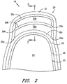
FIG. 2 shows an exemplary coating system positioned on a blade tip of a turbine blade; and -
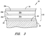
FIG. 3 shows a cross-sectional view of the exemplary coating system ofFIG. 2 at the blade tip. - Repeat use of reference characters in the present specification and drawings is intended to represent the same or analogous features or elements of the present invention.
- Reference now will be made in detail to embodiments of the invention, one or more examples of which are illustrated in the drawings. Each example is provided by way of explanation of the invention, not limitation of the invention. In fact, it will be apparent to those skilled in the art that various modifications and variations can be made in the present invention without departing from the scope or spirit of the invention. For instance, features illustrated or described as part of one embodiment can be used with another embodiment to yield a still further embodiment. Thus, it is intended that the present invention covers such modifications and variations as come within the scope of the appended claims and their equivalents.
- In the present disclosure, when a layer is being described as "on" or "over" another layer or substrate, it is to be understood that the layers can either be directly contacting each other or have another layer or feature between the layers, unless expressly stated to the contrary. Thus, these terms are simply describing the relative position of the layers to each other and do not necessarily mean "on top of" since the relative position above or below depends upon the orientation of the device to the viewer.
- Chemical elements are discussed in the present disclosure using their common chemical abbreviation, such as commonly found on a periodic table of elements. For example, hydrogen is represented by its common chemical abbreviation H; helium is represented by its common chemical abbreviation He; and so forth. "Ln" refers to the rare earth elements of scandium (Sc), yttrium (Y), lanthanum (La), cerium (Ce), praseodymium (Pr), neodymium (Nd), promethium (Pm), samarium (Sm), europium (Eu), gadolinium (Gd), terbium (Tb), dysprosium (Dy), holmium (Ho), erbium (Er), thulium (Tm), ytterbium (Yb), lutetium (Lu), or mixtures thereof. In particular embodiments, Ln is selected from the group consisting of neodymium, gadolinium, erbium, yttrium, and mixtures thereof.
- A coating for a CMC blade tip is generally provided herein, along with its methods of formation. The coating for the CMC blade tip is relatively thick, dense, and mechanically resistant to spall and rub in turbine engine environments. The coating is deposited via attaching at least two tapes filled with ceramic particles, sintering aids, organic binders, and plasticizers.
- The thick, tape-deposited sacrificial coating is generally provided in combination with a plurality of other, thinner layers to form an EBC on a CMC substrate. When applied to a blade tip, the sacrificial coating provides thickness that can rub away upon contact of the blade tip with a shroud. Thus, the sacrifice of this sacrificial coating during rub events serves to protect the underlying layers of the EBC, such as a relatively thin underlayer of bond coat that in turn protects the CMC from oxidation and/or a relatively thin underlayer of rare earth disilicate that in turn protects the CMC from high temperature steam penetration. It should also be noted that the sacrificial coating itself, may also provide some protection against high temperature steam penetration.
- In general, this overall coating system can be described as follows, from the CMC surface outward: a bond coat; one or more dense rare earth silicate layer(s); a first thick layer (at least about 0.2 mm (8 mils) and preferably at least about 0.38 mm (15 mils)) of rare earth disilicate matrix mixed with a discontinuous phase of barium strontium aluminosilicate
- (BSAS) or silicon metal particles (referred to herein as a "reinforced rare earth disilicate matrix"); one or more dense rare earth silicate layer(s); a second thick layer (at least about 0.2 mm (8 mils) and preferably at least about 0.38 mm (15 mils)) of a reinforced rare earth disilicate matrix, and the option of one or more rare earth silicate outer layer(s). Each of these layers is described in greater detail below with respect to particular embodiments provided herein.
-
Fig. 1 shows anexemplary turbine blade 10 of a gas turbine engine. Theblade 10 is generally represented as being adapted for mounting to a disk or rotor (not shown) within the turbine section of an aircraft gas turbine engine. For this reason, theblade 10 is represented as including adovetail 12 for anchoring theblade 10 to a turbine disk by interlocking with a complementary dovetail slot formed in the circumference of the disk. As represented inFIG. 1 , the interlocking features comprise protrusions referred to astangs 14 that engage recesses defined by the dovetail slot. Theblade 10 is further shown as having aplatform 16 that separates anairfoil 18 from ashank 15 on which thedovetail 12 is defined. - The
blade 10 includes ablade tip 19 disposed opposite theplatform 16. As such, theblade tip 19 generally defines the radially outermost portion of theblade 10 and, thus, may be configured to be positioned adjacent to a stationary shroud (not shown) of the gas turbine engine. As stated above, during use, theblade tip 19 may contact the shroud, causing a rub event between theblade tip 19 and the shroud. - In one particular embodiment, the
blade tip 19 may be further equipped with a blade tip shroud (not shown) which, in combination with tip shrouds of adjacent blades within the same stage, defines a band around the blades that is capable of reducing blade vibrations and improving airflow characteristics. By incorporating a seal tooth, blade tip shrouds are further capable of increasing the efficiency of the turbine by reducing combustion gas leakage between the blade tips and a shroud surrounding the blade tips. - Because they are directly subjected to hot combustion gases during operation of the engine, the
airfoil 18,platform 16 andblade tip 19 have very demanding material requirements. Theplatform 16 andblade tip 19 are further critical regions of a turbine blade in that they create the inner and outer flowpath surfaces for the hot gas path within the turbine section. In addition, theplatform 16 creates a seal to prevent mixing of the hot combustion gases with lower temperature gases to which theshank 20, itsdovetail 12 and the turbine disk are exposed, and theblade tip 19 is subjected to creep due to high strain loads and wear interactions between it and the shroud surrounding theblade tips 19. Thedovetail 12 is also a critical region in that it is subjected to wear and high loads resulting from its engagement with a dovetail slot and the high centrifugal loading generated by theblade 10. - Referring to
Figs. 2 and3 , acoating system 20 is shown forming athick EBC 22 on aCMC substrate 24 that defines theblade tip 19. In the exemplary embodiment shown, abond coat 26 is positioned on thesurface 25 of theCMC substrate 24. A first rareearth silicate coating 28a is on thebond coat 26 and is formed from at least one rare earth silicate layer. A firstsacrificial coating 30a of a reinforced rare earth disilicate matrix is positioned on the at least one rareearth silicate layer 28a. The firstsacrificial coating 30a has a thickness of about 0.1 mm (4 mils) to about 1.02 mm (40 mils) (e.g., about 0.2 mm (8 mils) to about 0.64 mm (25 mils), such as about 0.41 mm (16 mils) to about 0.61mm (24 mils)). A second rareearth silicate coating 28b is on the firstsacrificial coating 30a and is formed from at least one rare earth silicate layer. As such, a rare earth silicate coating (collectively 28a, 28b) surrounds the firstsacrificial coating 30a at theblade tip 19. A secondsacrificial coating 30b of a reinforced rare earth disilicate matrix is positioned on the second rareearth silicate layer 28b. The secondsacrificial coating 30b has a thickness of about 0.1 mm (4 mils) to about 1.02 mm (40 mils) (e.g., about 0.2 mm (8 mils) to about 0.64 mm (25 mils), such as about 0.41 mm (16 mils) to about 0.61 mm (24 mils)). A third rareearth silicate coating 28c is on the secondsacrificial coating 30b and is formed from at least one rare earth silicate layer. As such, a rare earth silicate coating (collectively 28b, 28c) surrounds the secondsacrificial coating 30b at theblade tip 19. Finally, anouter layer 32 is positioned on the third rareearth silicate coating 28c. Each of these layers is discussed in greater detail below. Also, it should be noted that more than two sacrificial coatings could be present in thecoating system 20, if desired. - As stated, the
bond coat 26 is positioned in theCMC substrate 24, and in most embodiments is in direct contact with theCMC surface 25. The bond coating generally provides oxidation protection to theunderlying CMC material 24. In one particular embodiment, thebond coat 26 is a silicon bond coat. - The first rare
earth silicate coating 28a generally provides hermeticity against high temperature steam. In one embodiment, the first rareearth silicate coating 28a is formed from at least one layer of a slurry-deposited yttrium ytterbium disilicate (YbYDS) layer. Other silicate layers can be present in the first rareearth silicate coating 28a in order to provide hermeticity against high temperature steam, such as YbDS, LuDS, TmDS, LuYDS, TmYDS, etc. (where Lu= Lutetium and Tm = Thulium), although any rare earth disilicate can be utilized. - The first
sacrificial coating 30a of a reinforced rare earth silicate matrix is generally formed by tape-depositing at least one BSAS-reinforced rare earth silicate layer to the desired thickness, such as about 0.1 mm (4 mils) to about 1.02 mm (40 mils) (e.g., about 0.2 mm (8 mils) to about 0.64 mm (25 mils), such as about 0.41 mm (16 mils) to about 0.61 mm (24 mils)). Multiple layers may be utilized to form the firstsacrificial coating 30a of the desired thickness. The firstsacrificial coating 30a generally provides thickness to theEBC 22 that can be sacrificed in a rub event by theblade tip 19 with another component in the engine (e.g., a vane). The rare earth silicate layers described with respect to the firstsacrificial coating 30a may be comprised of rare earth disilicates (e.g., YbYDS), rare earth monosilicates, or mixtures thereof. - The first
sacrificial coating 30a is deposited via a thick tape-deposition and sintering process, since it is very difficult to build up a thick coating on the tip of a blade by a thermal spray technique (since edge effects lead to spallation) or by slurry deposition processes (since it would require multiple applications and heat treatments to build appreciable thickness). According to the thick tape-deposition method, the tape is loaded with the matrix material, such as the matrix material similar to that currently used for slurry deposition of rare-earth disilicates. In this embodiment, a mixture of rare earth disilicate powder and sintering aids that promote coating densification at temperatures of about 2300 °F to about 2500 °F (compared to about 2800 °F in the absence of the sintering aids) is utilized. In this method, however, a plurality of coarse particles (e.g., BSAS particles, silicon particles, or a mixture thereof) are also included in the tape so that they are at a level of about 30% to about 65% by volume of the ceramic material, with the balance being the fine rare earth silicate powder and sintering aid. The coarse particles have, in one embodiment, an average particle size of about 5 microns to about 100 microns. The coarse particle addition helps overcome the problem of the slurry process such that one obtains a thick, crack free layer after heat treatment. The use of BSAS or silicon coarse particles, specifically, also helps keep the porosity in the layer low (on the order of about 20% by volume or less, and in some embodiments, as little as about 10% porosity or less). Other coarse particles, such as ZrO2, can result in porosity levels above 20% by volume. The matrix material also contains organic binder (e.g., polyvinyl butyral) and plasticizer (e.g., dibutyl phthalate or dipropylene glycol dibenzoate) so that the tape is flexible and tacky for the attachment to the CMC blade tip surface. The tape is formed from slurry that comprises all of the constituents mentioned above, plus one or more solvents. The slurry can be cast under a doctor blade with a gap set to a controlled thickness, onto a film (e.g., a polymeric film). The solvent is then removed by drying, yielding the tape. In certain embodiments, the drying temperature is about 15 °C to about 50 °C, and can be dried at room temperature (e.g., about 20 °C to about 25 °C). Drying can be accomplished for any suitable duration (e.g., about 30 minutes to about 50 hours). Thus, another advantage of the tape approach is that there is no drying process after the tape is attached to the blade tip that result in drying defects that alter the geometry of the thick tip. - The tapes can be transferred to the CMC substrate by any suitable method. For example, the tape can be transferred to the CMC substrate through applying pressure in combination with the tack of the tape or through applying pressure in combination with an elevated temperature, to get the tape to flow a bit into the roughness of the blade tip surface, and the tack of the tape. In either of these methods, the additional application of a solvent to the tape surface can increase its tack. In one particular embodiment, these methods can be utilized with the addition of slurry, such as rare earth disilicate and sintering aids but without the BSAS particles. The addition of the slurry tends to create a robust bond during sintering.
- Multiple tape transfers can be performed, in particular embodiments, to build the resulting first
sacrificial coating 30a to the desired thickness. - The second rare
earth silicate coating 28b also provides hermeticity against high temperature steam. In one embodiment, the second rareearth silicate coating 28b is formed from at least one layer of a slurry-deposited yttrium ytterbium disilicate (YbYDS) layer. Other silicate layers can be present in the second rareearth silicate coating 28b, similar to those described above with respect to the first rareearth silicate coating 28a in order to provide hermeticity against high temperature steam. - In one particular embodiment, the first rare
earth silicate coating 28a and the second rareearth silicate coating 28b are substantially identical in terms of composition. Referring toFig. 2 , the first rareearth silicate coating 28a and the second rareearth silicate coating 28b are extensions of the same rareearth silicate coating 28, but for their respective positioning to surround the sacrificial coating 30 at theblade tip 19. As shown, theseparation points 29a serve to split the rareearth silicate coating 28 into the first rareearth silicate coating 28a and the second rareearth silicate coating 28b positioned about the firstsacrificial coating 30a. In this embodiment, the firstsacrificial coating 30a is completely encased within the first rareearth silicate coating 28a and the second rareearth silicate coating 28b in order to form a hermetic seal against high temperature steam. Additionally, the second rareearth silicate coating 28b may provide additional mechanical stability for the underlying firstsacrificial coating 30a (e.g., formed from a BSAS-reinforced YbYDS layer). - Both the first rare
earth silicate coating 28a and the second rareearth silicate coating 28b can be formed via slurry deposition. In one embodiment, the first rareearth silicate coating 28a is deposited, followed by tape-deposition of the firstsacrificial coating 30a in the location desired. Then, the second rareearth silicate coating 28b can be deposited (e.g., via slurry deposition) onto the firstsacrificial coating 30a and the exposed first rareearth silicate coating 28a. Where there is no firstsacrificial coating 30a present (e.g., on the leading edge, the blade surface, the trailing edge, etc.), the second rareearth silicate coating 28b is merged with the first rareearth silicate coating 28a in order to form a single layer of the rareearth silicate coating 28. - As shown in
Figs. 2 and3 , the secondsacrificial coating 30b of a reinforced rare earth silicate matrix is generally formed by tape-depositing at least one BSAS-reinforced rare earth silicate layer to the desired thickness, such as about 0.1 mm (4 mils) to about 1.02 mm (40 mils) (e.g., about 0.2 mm (8 mils) to about 0.64 mm (25 mils), such as about 0.41 mm (16 mils) to about 0.61 mm (24 mils)). Multiple layers may be utilized to form the secondsacrificial coating 30b of the desired thickness. The secondsacrificial coating 30b generally provides thickness to theEBC 22 that can be sacrificed in a rub event by theblade tip 19 with another component in the engine (e.g., a vane). The rare earth silicate layers described with respect to the secondsacrificial coating 30b may be comprised of rare earth disilicates (e.g., YbYDS), rare earth monosilicates, or mixtures thereof. The secondsacrificial coating 30b may be formed by any of the methods discussed above with respect to the firstsacrificial coating 30a. - The third rare
earth silicate coating 28c provides hermeticity against high temperature steam. In one embodiment, the third rareearth silicate coating 28c is formed from at least one layer of a slurry-deposited yttrium ytterbium disilicate (YbYDS) layer. Other silicate layers can be present in the third rareearth silicate coating 28c, similar to those described above with respect to the first rareearth silicate coating 28a in order to provide hermeticity against high temperature steam. - In one particular embodiment, the second rare
earth silicate coating 28b and the third rareearth silicate coating 28c are substantially identical in terms of composition. Referring toFig. 2 , the second rareearth silicate coating 28b and the third rareearth silicate coating 28c are extensions of the same rareearth silicate coating 28, but for their respective positioning to surround the secondsacrificial coating 30b at theblade tip 19. As shown, the separation points 29b serve to split the rareearth silicate coating 28 into the second rareearth silicate coating 28b and the third rareearth silicate coating 28c positioned about the secondsacrificial coating 30b. In this embodiment, the secondsacrificial coating 30b is completely encased within the second rareearth silicate coating 28b and the third rareearth silicate coating 28c in order to form a hermetic seal against high temperature steam. Additionally, the third rareearth silicate coating 28c may provide additional mechanical stability for the underlying secondsacrificial coating 30b (e.g., formed from a BSAS-reinforced YbYDS layer). - Like both the first rare
earth silicate coating 28a and the second rareearth silicate coating 28b, the third rareearth silicate coating 28c can be formed via slurry deposition. In one embodiment, the second rareearth silicate coating 28b is deposited, followed by tape-deposition of the secondsacrificial coating 30b in the location desired. Then, the third rareearth silicate coating 28c can be deposited (e.g., via slurry deposition) onto the secondsacrificial coating 30b and the exposed first secondearth silicate coating 28b. Where there is no secondsacrificial coating 30b present (e.g., on the leading edge, the blade surface, the trailing edge, etc.), the third rareearth silicate coating 28c is merged with the second rareearth silicate coating 28b in order to form a single layer of the rareearth silicate coating 28. - Thus, in one embodiment, each of the first rare
earth silicate coating 28a, the second rareearth silicate coating 28b, and the third rareearth silicate coating 28c are made with a substantially identical composition. - Finally, an
outer layer 32 is positioned on the third rareearth silicate coating 28c. In one embodiment, theouter layer 32 comprises at least one slurry-deposited yttrium monosilicate (YMS) layer. Theouter layer 32 provides protection against steam recession and molten dust. Materials other than rare earth silicates can be utilized within the outer coating, such as rare earth hafnates, rare earth zirconates, rare earth gallates (e.g., monoclinic type, such as Ln4Ga2O9), rare earth monotitanate (e.g., Ln2TiO5), rare earth cerate (e.g., Ln2CeO5), rare earth germinate (e.g., Ln2GeO5), or mixtures thereof. However, all of these materials have a relatively high coeffiecient of thermal expansion (CTE) compared to rare earth silicate. Thus, rare earth monosilicate is preferred. Hafnia, rare-earth stabilized hafnia, and rare-earth stabilized zirconia provide protection against steam recession but not CMAS, and also have higher CTE than rare earth monosilicate. - In addition to a thick coating on the
blade tip 19, theEBC 20 can be used as an alternate method to obtain a thick EBC coating on other components or areas of a CMC component (e.g., on a shroud, etc.). - While the invention has been described in terms of one or more particular embodiments, it is apparent that other forms could be adopted by one skilled in the art. It is to be understood that the use of "comprising" in conjunction with the coating compositions described herein specifically discloses and includes the embodiments wherein the coating compositions "consist essentially of" the named components (i.e., contain the named components and no other components that significantly adversely affect the basic and novel features disclosed), and embodiments wherein the coating compositions "consist of" the named components (i.e., contain only the named components except for contaminants which are naturally and inevitably present in each of the named components).
- This written description uses examples to disclose the invention, including the best mode, and also to enable any person skilled in the art to practice the invention, including making and using any devices or systems and performing any incorporated methods. The patentable scope of the invention is defined by the claims, and may include other examples that occur to those skilled in the art. Such other examples are intended to be within the scope of the claims if they include structural elements that do not differ from the literal language of the claims, or if they include equivalent structural elements with insubstantial differences from the literal languages of the claims.
Claims (15)
- A coating system (20) on a CMC substrate (24), the coating system (20) comprising:a first rare earth silicate coating (28a) on the CMC substrate (24), wherein the first rare earth silicate coating (28a) comprises at least one rare earth silicate layer;a first sacrificial coating (30a) of a first reinforced rare earth silicate matrix on the at least one rare earth silicate layer, wherein the first sacrificial coating (30a) has a thickness of about 0.1 mm (4 mils) to about 1.02 mm (40 mils);a second rare earth silicate coating (28b) on the sacrificial coating, wherein the second rare earth silicate coating (28b) comprises at least one rare earth silicate layer;a second sacrificial coating (30b) of a second reinforced rare earth silicate matrix on the second rare earth silicate coating (28b), wherein the second sacrificial coating (30b) has a thickness of about 0.1 mm (4 mils) to about 1.02 mm (40 mils); anda third rare earth silicate coating (28c) on the second sacrificial coating (30b), wherein the third rare earth silicate coating (28c) comprises at least one rare earth silicate layer;an outer layer (32) on the third rare earth silicate coating (28c).
- The coating system (20) of claim 1, wherein the first sacrificial coating (30a) has a thickness of about 0.2 mm (8 mils) to about 0.64 mm (25 mils), and wherein the second sacrificial coating (30b) has a thickness of about 0.2 mm (8 mils) to about 0.64 mm (25 mils).
- The coating system (20) of claim 1, wherein the first sacrificial coating (30a) has a thickness of about 0.41 mm (16 mils) to about 0.61 mm (24 mils), and wherein the second sacrificial coating (30b) has a thickness of about 0.2 mm (8 mils) to about 0.64 mm (25 mils).
- The coating system (20) of claim 1, wherein the reinforced rare earth silicate matrix of the first sacrificial coating (30a) and of the second sacrificial coating (30b) comprises a rare earth silicate mixed with a discontinuous phase of barium strontium aluminosilicate.
- The coating system (20) of claim 1, wherein the reinforced rare earth silicate matrix of the first sacrificial coating (30a) and of the second sacrificial coating (30b) comprises a rare earth silicate mixed with a discontinuous phase of silicon metal particles.
- The coating system (20) of claim 1, wherein the reinforced rare earth silicate matrix of the first sacrificial coating (30a) and of the second sacrificial coating (30b) comprises a rare earth disilicate.
- The coating system (20) of claim 1, wherein the reinforced rare earth silicate matrix of the first sacrificial coating (30a) and of the second sacrificial coating (30b) comprises a rare earth monosilicate.
- The coating system (20) of claim 1, wherein the reinforced rare earth silicate matrix of the first sacrificial coating (30a) and of the second sacrificial coating (30b) comprises a mixture of a rare earth monosilicate and a rare earth disilicate.
- The coating system (20) of claim 1, further comprising;
a bond coat (26) on a surface of the CMC substrate (24), wherein the bond coat (26) is a silicon bond coat (26). - The coating system (20) of claim 1, wherein the first rare earth silicate coating (28a), the second rare earth silicate coating (28b), and the third rare earth silicate coating (28c) have a substantially identical composition.
- A blade, comprising:an airfoil comprising a CMC substrate (24) and defining a blade tip; wherein the blade tip has the coating system (20) of claim 1 thereon.
- A method of tape deposition of a sacrificial coating on a CMC substrate (24), the method comprising:applying a first matrix material onto a surface of a first film, wherein the first matrix material comprises a mixture of a rare earth silicate powder, a sintering aid, and a solvent;drying the first matrix material to remove the solvent forming a first tape having a film side and a matrix side;applying the first tape onto the CMC substrate (24) with the matrix side facing the CMC substrate (24);applying a second matrix material onto a surface of a second film, wherein the second matrix material comprises a mixture of a rare earth silicate powder, a sintering aid, and a solvent;applying the second tape onto the CMC substrate (24) with the matrix side facing the CMC substrate (24); andsintering the first tape and the second tape to bond the first matrix material to the CMC substrate (24) via a first bonding layer and to bond the second matrix material to the first matrix material via a second bonding layer.
- The method of claim 12, wherein the first matrix material further comprises a plurality of coarse particles, and wherein the coarse particles comprise coarse BSAS particles, silicon particles, or a mixture thereof, and wherein the coarse particles have an average particle size of about 5 microns to about 100 microns.
- The method of claim 13, wherein the coarse particles comprise about 30% to about 65% by volume of the matrix material after drying, with the balance being the rare earth silicate powder and the sintering aid.
- The method of claim 13, wherein the first tape forms a first sacrificial coating (30a) of a first reinforced rare earth silicate matrix having a thickness of about 0.1 mm (4 mils) to about 1.02 mm (40 mils); and wherein the second tape forms a second sacrificial coating (30b) of a second reinforced rare earth silicate matrix having a thickness of about 0.1 mm (4 mils) to about 1.02 mm (40 mils).
Applications Claiming Priority (1)
| Application Number | Priority Date | Filing Date | Title |
|---|---|---|---|
| US14/797,235 US10392947B2 (en) | 2015-07-13 | 2015-07-13 | Compositions and methods of attachment of thick environmental barrier coatings on CMC components |
Publications (1)
| Publication Number | Publication Date |
|---|---|
| EP3118179A1 true EP3118179A1 (en) | 2017-01-18 |
Family
ID=56551156
Family Applications (1)
| Application Number | Title | Priority Date | Filing Date |
|---|---|---|---|
| EP16178851.8A Withdrawn EP3118179A1 (en) | 2015-07-13 | 2016-07-11 | Coating system on a ceramic matrix composite substrate and method of deposition of a sacrificial coating on a ceramic matrix composite substrate |
Country Status (5)
| Country | Link |
|---|---|
| US (1) | US10392947B2 (en) |
| EP (1) | EP3118179A1 (en) |
| JP (1) | JP2017019713A (en) |
| CN (1) | CN106699234B (en) |
| CA (1) | CA2934628A1 (en) |
Cited By (1)
| Publication number | Priority date | Publication date | Assignee | Title |
|---|---|---|---|---|
| US12351523B2 (en) | 2019-04-11 | 2025-07-08 | Axiom Materials, Inc. | Surface treatments for ceramic coated/impregnated materials |
Families Citing this family (8)
| Publication number | Priority date | Publication date | Assignee | Title |
|---|---|---|---|---|
| US9896954B2 (en) * | 2014-10-14 | 2018-02-20 | Rolls-Royce Corporation | Dual-walled ceramic matrix composite (CMC) component with integral cooling and method of making a CMC component with integral cooling |
| US10472976B2 (en) * | 2015-06-05 | 2019-11-12 | Rolls-Royce Corporation | Machinable CMC insert |
| US10458653B2 (en) * | 2015-06-05 | 2019-10-29 | Rolls-Royce Corporation | Machinable CMC insert |
| US10465534B2 (en) | 2015-06-05 | 2019-11-05 | Rolls-Royce North American Technologies, Inc. | Machinable CMC insert |
| CN107523298B (en) * | 2017-08-07 | 2021-04-30 | 温州大学 | Yttrium cerium composite oxide based up-conversion luminescent material and preparation method thereof |
| US11739650B2 (en) * | 2018-02-27 | 2023-08-29 | Rolls-Royce Corporation | Hybrid airfoil coatings |
| US11542208B2 (en) | 2020-02-07 | 2023-01-03 | Raytheon Technologies Corporation | Environmental barrier coating |
| US12006269B2 (en) * | 2021-08-25 | 2024-06-11 | Honeywell International Inc. | Multilayer protective coating systems for gas turbine engine applications and methods for fabricating the same |
Citations (2)
| Publication number | Priority date | Publication date | Assignee | Title |
|---|---|---|---|---|
| US20090162674A1 (en) * | 2007-12-20 | 2009-06-25 | Brett Allen Boutwell | Tapes comprising barrier coating compositions and components comprising the same |
| US20140037969A1 (en) * | 2012-08-03 | 2014-02-06 | General Electric Company | Hybrid Air Plasma Spray and Slurry Method of Environmental Barrier Deposition |
Family Cites Families (36)
| Publication number | Priority date | Publication date | Assignee | Title |
|---|---|---|---|---|
| US6383602B1 (en) | 1996-12-23 | 2002-05-07 | General Electric Company | Method for improving the cooling effectiveness of a gaseous coolant stream which flows through a substrate, and related articles of manufacture |
| US6299988B1 (en) | 1998-04-27 | 2001-10-09 | General Electric Company | Ceramic with preferential oxygen reactive layer |
| US6234755B1 (en) | 1999-10-04 | 2001-05-22 | General Electric Company | Method for improving the cooling effectiveness of a gaseous coolant stream, and related articles of manufacture |
| US6904757B2 (en) | 2002-12-20 | 2005-06-14 | General Electric Company | Mounting assembly for the forward end of a ceramic matrix composite liner in a gas turbine engine combustor |
| JP3997986B2 (en) | 2003-12-19 | 2007-10-24 | 株式会社Ihi | Cooling turbine component and cooling turbine blade |
| US7328580B2 (en) | 2004-06-23 | 2008-02-12 | General Electric Company | Chevron film cooled wall |
| US20060154093A1 (en) * | 2005-01-13 | 2006-07-13 | General Electric Company | Multilayered environmental barrier coating and related articles and methods |
| US20060188736A1 (en) * | 2005-02-18 | 2006-08-24 | General Electric Company | Diffusion barrier for assemblies with metallic and silicon-containing components and method therefor |
| US7442444B2 (en) * | 2005-06-13 | 2008-10-28 | General Electric Company | Bond coat for silicon-containing substrate for EBC and processes for preparing same |
| JP4752841B2 (en) | 2005-11-01 | 2011-08-17 | 株式会社Ihi | Turbine parts |
| US7997867B1 (en) | 2006-10-17 | 2011-08-16 | Iowa State University Research Foundation, Inc. | Momentum preserving film-cooling shaped holes |
| US9365725B2 (en) | 2007-11-16 | 2016-06-14 | General Electric Company | Articles for high temperature service and methods for their manufacture |
| EP2344590B1 (en) * | 2008-09-30 | 2016-11-30 | Rolls-Royce Corporation | Coating including a rare earth silicate-based layer including a second phase |
| US8057179B1 (en) | 2008-10-16 | 2011-11-15 | Florida Turbine Technologies, Inc. | Film cooling hole for turbine airfoil |
| US8057181B1 (en) | 2008-11-07 | 2011-11-15 | Florida Turbine Technologies, Inc. | Multiple expansion film cooling hole for turbine airfoil |
| KR20110130437A (en) | 2009-03-09 | 2011-12-05 | 니토 보세키 가부시기가이샤 | Glass Melting Apparatus for Glass Fiber Production, and Manufacturing Method of Glass Fiber |
| US8501840B2 (en) * | 2009-07-31 | 2013-08-06 | General Electric Company | Water based slurry compositions for making environmental barrier coatings and environmental barrier coatings comprising the same |
| US20110097191A1 (en) | 2009-10-28 | 2011-04-28 | General Electric Company | Method and structure for cooling airfoil surfaces using asymmetric chevron film holes |
| US20110203281A1 (en) | 2010-02-25 | 2011-08-25 | General Electric Company | Article for high temperature service |
| JP4954309B2 (en) | 2010-03-24 | 2012-06-13 | 川崎重工業株式会社 | Double jet film cooling structure |
| US8727730B2 (en) * | 2010-04-06 | 2014-05-20 | General Electric Company | Composite turbine bucket assembly |
| US20130136915A1 (en) * | 2010-04-30 | 2013-05-30 | Rolls-Royce Corporation | Durable environmental barrier coatings for ceramic substrates |
| US8943835B2 (en) | 2010-05-10 | 2015-02-03 | General Electric Company | Gas turbine engine combustor with CMC heat shield and methods therefor |
| US8905713B2 (en) | 2010-05-28 | 2014-12-09 | General Electric Company | Articles which include chevron film cooling holes, and related processes |
| US9181819B2 (en) | 2010-06-11 | 2015-11-10 | Siemens Energy, Inc. | Component wall having diffusion sections for cooling in a turbine engine |
| US8572981B2 (en) | 2010-11-08 | 2013-11-05 | General Electric Company | Self-oscillating fuel injection jets |
| US8777583B2 (en) | 2010-12-27 | 2014-07-15 | General Electric Company | Turbine airfoil components containing ceramic-based materials and processes therefor |
| US9023486B2 (en) | 2011-10-13 | 2015-05-05 | General Electric Company | Thermal barrier coating systems and processes therefor |
| US8850828B2 (en) | 2012-02-15 | 2014-10-07 | United Technologies Corporation | Cooling hole with curved metering section |
| US8733111B2 (en) | 2012-02-15 | 2014-05-27 | United Technologies Corporation | Cooling hole with asymmetric diffuser |
| US9273560B2 (en) | 2012-02-15 | 2016-03-01 | United Technologies Corporation | Gas turbine engine component with multi-lobed cooling hole |
| US8584470B2 (en) | 2012-02-15 | 2013-11-19 | United Technologies Corporation | Tri-lobed cooling hole and method of manufacture |
| US9422815B2 (en) | 2012-02-15 | 2016-08-23 | United Technologies Corporation | Gas turbine engine component with compound cusp cooling configuration |
| US9279330B2 (en) | 2012-02-15 | 2016-03-08 | United Technologies Corporation | Gas turbine engine component with converging/diverging cooling passage |
| US10386069B2 (en) | 2012-06-13 | 2019-08-20 | General Electric Company | Gas turbine engine wall |
| US9410437B2 (en) | 2012-08-14 | 2016-08-09 | General Electric Company | Airfoil components containing ceramic-based materials and processes therefor |
-
2015
- 2015-07-13 US US14/797,235 patent/US10392947B2/en active Active
-
2016
- 2016-06-30 CA CA2934628A patent/CA2934628A1/en not_active Abandoned
- 2016-07-05 JP JP2016132939A patent/JP2017019713A/en active Pending
- 2016-07-11 EP EP16178851.8A patent/EP3118179A1/en not_active Withdrawn
- 2016-07-13 CN CN201610548560.XA patent/CN106699234B/en active Active
Patent Citations (2)
| Publication number | Priority date | Publication date | Assignee | Title |
|---|---|---|---|---|
| US20090162674A1 (en) * | 2007-12-20 | 2009-06-25 | Brett Allen Boutwell | Tapes comprising barrier coating compositions and components comprising the same |
| US20140037969A1 (en) * | 2012-08-03 | 2014-02-06 | General Electric Company | Hybrid Air Plasma Spray and Slurry Method of Environmental Barrier Deposition |
Cited By (1)
| Publication number | Priority date | Publication date | Assignee | Title |
|---|---|---|---|---|
| US12351523B2 (en) | 2019-04-11 | 2025-07-08 | Axiom Materials, Inc. | Surface treatments for ceramic coated/impregnated materials |
Also Published As
| Publication number | Publication date |
|---|---|
| US10392947B2 (en) | 2019-08-27 |
| US20170016335A1 (en) | 2017-01-19 |
| JP2017019713A (en) | 2017-01-26 |
| CN106699234A (en) | 2017-05-24 |
| CN106699234B (en) | 2020-11-17 |
| CA2934628A1 (en) | 2017-01-13 |
Similar Documents
| Publication | Publication Date | Title |
|---|---|---|
| US11078798B2 (en) | Methods of deposition of thick environmental barrier coatings on CMC blade tips | |
| US10392947B2 (en) | Compositions and methods of attachment of thick environmental barrier coatings on CMC components | |
| CN106979039B (en) | For CMC shield can wear compound and method | |
| JP5802390B2 (en) | How to repair a barrier coating | |
| CN109424369B (en) | Turbine blade including coating system and method of forming turbine blade | |
| JP5595416B2 (en) | Method for making a ceramic component having environmental barrier coating and CMAS mitigation capabilities | |
| EP2644747A2 (en) | Fiber-reinforced barrier coating, method of applying barrier coating to component and turbomachinery component | |
| JP2011507790A (en) | Method for producing a tape cast barrier coating, components comprising the same, and tape produced thereby | |
| JP2011507789A (en) | Tape comprising barrier coating composition and component comprising the same | |
| EP3597871B1 (en) | Environmental barrier multi-phase abradable coating | |
| CN109422533B (en) | Coating system on substrate surface, coated component, and coating forming method | |
| US20140011038A1 (en) | Coating system for a gas turbine component | |
| US20180087387A1 (en) | Compositions and methods for coating metal turbine blade tips | |
| EP4653669A1 (en) | Abradable coating | |
| EP4711352A1 (en) | Ceramic coatings with sintering agents |
Legal Events
| Date | Code | Title | Description |
|---|---|---|---|
| PUAI | Public reference made under article 153(3) epc to a published international application that has entered the european phase |
Free format text: ORIGINAL CODE: 0009012 |
|
| AK | Designated contracting states |
Kind code of ref document: A1 Designated state(s): AL AT BE BG CH CY CZ DE DK EE ES FI FR GB GR HR HU IE IS IT LI LT LU LV MC MK MT NL NO PL PT RO RS SE SI SK SM TR |
|
| AX | Request for extension of the european patent |
Extension state: BA ME |
|
| 17P | Request for examination filed |
Effective date: 20170718 |
|
| RBV | Designated contracting states (corrected) |
Designated state(s): AL AT BE BG CH CY CZ DE DK EE ES FI FR GB GR HR HU IE IS IT LI LT LU LV MC MK MT NL NO PL PT RO RS SE SI SK SM TR |
|
| STAA | Information on the status of an ep patent application or granted ep patent |
Free format text: STATUS: THE APPLICATION IS DEEMED TO BE WITHDRAWN |
|
| 18D | Application deemed to be withdrawn |
Effective date: 20190201 |