EP3118106A1 - Methods and control systems for controlling a drive system of an aircraft - Google Patents
Methods and control systems for controlling a drive system of an aircraft Download PDFInfo
- Publication number
- EP3118106A1 EP3118106A1 EP16275098.8A EP16275098A EP3118106A1 EP 3118106 A1 EP3118106 A1 EP 3118106A1 EP 16275098 A EP16275098 A EP 16275098A EP 3118106 A1 EP3118106 A1 EP 3118106A1
- Authority
- EP
- European Patent Office
- Prior art keywords
- torque
- level
- drive motor
- rotation speed
- control system
- Prior art date
- Legal status (The legal status is an assumption and is not a legal conclusion. Google has not performed a legal analysis and makes no representation as to the accuracy of the status listed.)
- Pending
Links
- 238000000034 method Methods 0.000 title claims abstract description 18
- 238000004590 computer program Methods 0.000 claims description 2
- 230000001419 dependent effect Effects 0.000 description 2
- 238000010586 diagram Methods 0.000 description 2
- 238000004364 calculation method Methods 0.000 description 1
- 230000005484 gravity Effects 0.000 description 1
- 230000000977 initiatory effect Effects 0.000 description 1
Images


Classifications
-
- B—PERFORMING OPERATIONS; TRANSPORTING
- B64—AIRCRAFT; AVIATION; COSMONAUTICS
- B64D—EQUIPMENT FOR FITTING IN OR TO AIRCRAFT; FLIGHT SUITS; PARACHUTES; ARRANGEMENTS OR MOUNTING OF POWER PLANTS OR PROPULSION TRANSMISSIONS IN AIRCRAFT
- B64D31/00—Power plant control; Arrangement thereof
-
- B—PERFORMING OPERATIONS; TRANSPORTING
- B64—AIRCRAFT; AVIATION; COSMONAUTICS
- B64C—AEROPLANES; HELICOPTERS
- B64C25/00—Alighting gear
- B64C25/32—Alighting gear characterised by elements which contact the ground or similar surface
- B64C25/405—Powered wheels, e.g. for taxing
-
- B—PERFORMING OPERATIONS; TRANSPORTING
- B64—AIRCRAFT; AVIATION; COSMONAUTICS
- B64C—AEROPLANES; HELICOPTERS
- B64C19/00—Aircraft control not otherwise provided for
-
- B—PERFORMING OPERATIONS; TRANSPORTING
- B60—VEHICLES IN GENERAL
- B60L—PROPULSION OF ELECTRICALLY-PROPELLED VEHICLES; SUPPLYING ELECTRIC POWER FOR AUXILIARY EQUIPMENT OF ELECTRICALLY-PROPELLED VEHICLES; ELECTRODYNAMIC BRAKE SYSTEMS FOR VEHICLES IN GENERAL; MAGNETIC SUSPENSION OR LEVITATION FOR VEHICLES; MONITORING OPERATING VARIABLES OF ELECTRICALLY-PROPELLED VEHICLES; ELECTRIC SAFETY DEVICES FOR ELECTRICALLY-PROPELLED VEHICLES
- B60L2200/00—Type of vehicles
- B60L2200/10—Air crafts
-
- Y—GENERAL TAGGING OF NEW TECHNOLOGICAL DEVELOPMENTS; GENERAL TAGGING OF CROSS-SECTIONAL TECHNOLOGIES SPANNING OVER SEVERAL SECTIONS OF THE IPC; TECHNICAL SUBJECTS COVERED BY FORMER USPC CROSS-REFERENCE ART COLLECTIONS [XRACs] AND DIGESTS
- Y02—TECHNOLOGIES OR APPLICATIONS FOR MITIGATION OR ADAPTATION AGAINST CLIMATE CHANGE
- Y02T—CLIMATE CHANGE MITIGATION TECHNOLOGIES RELATED TO TRANSPORTATION
- Y02T50/00—Aeronautics or air transport
- Y02T50/80—Energy efficient operational measures, e.g. ground operations or mission management
Definitions
- the present invention methods and control systems for controlling a drive system of an aircraft. More particularly, but not exclusively, the invention concerns the control of an electrical drive system installed on an aircraft landing gear, using a desired power level for the drive system.
- the taxiing of aircraft while on the ground is conventionally performed using thrust provided by the engines of the aircraft.
- Control of movement of an aircraft while on the ground using the aircraft's engines is achieved by use of the engine thrust controller.
- the equivalent control is achieved using a torque controller, with which the pilot (or other person controlling the aircraft) commands a percentage of available torque (i.e. turning force) to the drive motors.
- the torque required for movement of the aircraft to begin can vary dependent upon the operating conditions. This is because the "breakaway resistance" of the aircraft will vary dependent upon various factors, such as the aircraft mass (which varies depending for different loads), centre of gravity, weather conditions, runway conditions (e.g. dry, wet, icy, sandy, rough, smooth), and any slope on which the aircraft is positioned, for example.
- the torque is not sufficient to initiation movement of the aircraft, damage to the drive motors may be caused. If on the other hand a large torque is commanded in order to overcome a potentially large breakaway resistance, this can lead to undesirable "jerking" of the aircraft as movement is initiated.
- the present invention seeks to mitigate the above-mentioned problems. Alternatively or additionally, the present invention seeks to provide improved methods and control systems for controlling a drive system of an aircraft.
- a method of controlling a drive system of an aircraft wherein the drive system comprises a drive motor arranged to drive at least one wheel of the aircraft landing gear, the method comprising the steps of:
- the torque level may be determined by dividing the power level indicated by the power signal by the rotation speed indicated by the speed signal.
- the torque level may be determined using a calculation based on dividing the power level indicated by the power signal by the rotation speed indicated by the speed signal, but with further additional refinements.
- the torque level is at most a predefined maximum torque level. This may be the maximum torque level specified for the drive motor, i.e. the maximum torque level the drive motor is able to deliver.
- the torque level is, if non-zero, at least a predefined minimum torque level. This may be a minimum torque level specified for the drive motor.
- the torque level is increased over time by at most a predefined maximum torque rate. This further helps to provide smooth movement of the aircraft when there are large changes in the power level indicated for the drive motor. It also helps to provide smooth movement when the rotation speed of the drive motor changes, particularly at very low rotation speeds.
- the torque level is determined using the predefined minimum rotation speed. This prevents “spikes” occurring in the determined torque level when the rotation speed is very low.
- the power level indicated by the power signal is a percentage of a predefined maximum power level.
- the rotation speed indicated by the speed signal may be determined from sensors on the drive motor. Alternatively and/or additionally, the rotation speed indicated by the speed signal may be determined from the operating properties of the drive motor.
- a control system for controlling an aircraft wheel drive system wherein the drive system comprises a drive motor arranged to drive at least one wheel of the aircraft landing gear, and wherein the control system is arranged to:
- the control system may be arranged to determine the torque level by dividing the power level indicated by the power signal by the rotation speed indicated by the speed signal.
- control system is arranged to determine the torque level to be at most a predefined maximum torque level.
- control system is arranged to determine the torque level to be, if non-zero, at most a predefined minimum torque level.
- control system is arranged to increase the torque level over time by at most a predefined maximum torque rate.
- control system is arranged, if the rotation speed indicated by the speed signal is below a predefined minimum rotation speed, to determine the torque level using the predefined minimum rotation speed.
- the power level indicated by the power signal is a percentage of a predefined maximum power level.
- the control system may be arranged to determine the rotation speed indicated by the speed signal using sensors on the drive motor.
- a computer program product arranged, when executed on a computing device of an aircraft, to provide a control system that performs any of the methods described above, or any of the control systems described above.
- an aircraft comprising a control system that performs any of the methods described above, or any of the control systems described above.
- Figure 1 is a schematic diagram of the control system.
- the control system 1 takes as input a desired power level 11, which indicates the level of power that the pilot wishes the drive motors driving the wheels of the aircraft landing gear to use.
- the desired power level 11 is commanded by the pilot using a power indicator, which may be a pedal, handle or the like.
- the desired power level 11 can range between 0 and 100, and is scaled by a first gain block 12 with a factor of 0.01 to give a value between 0 and 1.
- a multiplier block 14 takes as input the output of the first gain block 12 and a maximum power level 14 for the drive motor. (The maximum power level 14 is predefined as a design characteristic of the control system 1.) Consequently, the output of the multiplier block 13 will be a power level ranging from 0 to the maximum power level, as commanded by the pilot.
- the control system 1 also takes as input the wheel rotation speed 15 of the wheels of the aircraft landing gear, as supplied by a tachometer or other rotation speed sensing device.
- a first max block 17 takes as input the wheel rotation speed 15, and also a minimum rotation speed 16. (The minimum rotation speed 16 is again a predefined value, used as discussed below to prevent "divide by zero" errors when the wheels are stationary.) Consequently, the output of the first max block 17 is the wheel rotation speed 15, or the minimum rotation speed 16 if the wheel rotation speed 15 is below the minimum rotation speed 16 (for example if the wheels are stationary so the wheel rotation speed 15 is zero).
- a second divider block 20 takes as input the output of the first divider block 18 and a maximum motor torque 19, in such a way that the output of the second divider block 20 is that of the first divider block 18 divided by the maximum motor torque 19.
- the maximum motor torque 19 is an operating property of the drive motors of the aircraft landing gear, and is again predefined as a design characteristic of the control system 1.
- the minimum rotation speed 16 and maximum power level 14 are preferably predefined at suitable levels so that the desired level of torque output by the first divider block 18 is at most the maximum motor torque 19, and so the output of the second divider block 20 is between 0 and 1.
- the output of the second divider block 20 is then scaled by a second gain block 21 with a factor of 100, to give a torque demand percentage value that should range between 0 and 100.
- the output of the second gain block 21 is passed through a rate-limiter filter block 22, which limits the rate at which the torque demand percentage value can change.
- the output of the second gain block 21 may also be passed through a saturation filter block (not shown), which limits the torque demand percentage value to be in the range of 0 to 100 should the minimum rotation speed 16 or maximum power level 14 be defined at values which allow that to occur.
- the torque demand percentage value output by the saturation filter block 22 is passed as a selectable input to a first switch 23, which also takes an alternative selectable input a zero value 24.
- a non-negative check block 25 takes as input the wheel rotation speed 15, and outputs a 1 if the wheel rotation speed 15 is zero or above (i.e. the aircraft landing gear wheels are not moving backwards), and 0 if it is below zero.
- the output of the non-negative check block 25 is passed as the selecting input to the first switch 23, so that torque demand percentage value is selected if the wheel rotation speed 15 is zero or above, and otherwise zero.
- a second max block 25 takes as input the output of the first switch 23, and a minimum torque percentage value 26.
- the minimum torque percentage value 26 is again predefined as a design characteristic of the control system 1.
- the output of the second max block 25 is the torque demand percentage value output by the saturation filter block 22, or the minimum torque percentage value 26 if the torque demand percentage value is below the minimum torque percentage value 26, or if the wheel rotation speed 15 is below zero (and so the output of the first switch 23 is zero).
- the output of the second max block 25 is passed as a selectable input to a second switch 27, which also takes an alternative selectable input a zero value 28.
- a positive check block 29 takes as input the desired power level 11, and outputs a 1 if the desired power level 11 is above zero, and 0 if it is zero or below.
- the output of the positive check block 29 is passed as the selecting input to the second switch 27, so that output of the second max block 25 is selected if the desired power level 11 is above zero, and otherwise zero.
- the output of the second switch 27 is the torque demand percentage 30 with which the control system 1 drives the drive motors of the aircraft landing gear.
- Figure 2 shows the desired power level 11 for control system 1 over time.
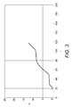
- FIG. 3 shows the corresponding wheel rotation speed of the drive motor of the aircraft landing gear
- Figure 4 shows the corresponding torque level determined by the control system 1.
- Figure 5 shows an aircraft 100 incorporating the control system described above.
Abstract
Description
- The present invention methods and control systems for controlling a drive system of an aircraft. More particularly, but not exclusively, the invention concerns the control of an electrical drive system installed on an aircraft landing gear, using a desired power level for the drive system.
- The taxiing of aircraft while on the ground is conventionally performed using thrust provided by the engines of the aircraft. However, it can be desirable to provide thrust through a wheel drive taxi system; in other words, an aircraft with landing gear incorporating drive motors, which drive the wheels to move the aircraft while it is on the ground.
- Control of movement of an aircraft while on the ground using the aircraft's engines is achieved by use of the engine thrust controller. In known wheel drive taxi systems, the equivalent control is achieved using a torque controller, with which the pilot (or other person controlling the aircraft) commands a percentage of available torque (i.e. turning force) to the drive motors.
- However, when stationary, the torque required for movement of the aircraft to begin can vary dependent upon the operating conditions. This is because the "breakaway resistance" of the aircraft will vary dependent upon various factors, such as the aircraft mass (which varies depending for different loads), centre of gravity, weather conditions, runway conditions (e.g. dry, wet, icy, sandy, rough, smooth), and any slope on which the aircraft is positioned, for example. When the torque is not sufficient to initiation movement of the aircraft, damage to the drive motors may be caused. If on the other hand a large torque is commanded in order to overcome a potentially large breakaway resistance, this can lead to undesirable "jerking" of the aircraft as movement is initiated.
- The present invention seeks to mitigate the above-mentioned problems. Alternatively or additionally, the present invention seeks to provide improved methods and control systems for controlling a drive system of an aircraft.
- In accordance with a first aspect of the invention, there is provided a method of controlling a drive system of an aircraft, wherein the drive system comprises a drive motor arranged to drive at least one wheel of the aircraft landing gear, the method comprising the steps of:
- receiving a power signal indicative of a power level for the drive motor;
- receiving a speed signal indicative of a rotation speed of the drive motor;
- determining a torque level for the drive motor using the power signal and the speed signal;
- driving the drive motor such that the torque generated by the drive motor is at the determined torque level.
- By using a power level to determine how the motor is driven, this causes a higher level of torque to be used at lower rotation speeds for any given power level, as torque = power / rotation speed. This means that a sufficiently high level of torque should always be provided to overcome the aircraft's breakaway resistance (assuming it is within the operating capabilities of the drive motor), as at very low rotation speeds a very high torque level will be required in order to provide the power level indicated. However, as the aircraft begins to move the rotation speed will increase, meaning that a lower level of torque is provided to give the same power level. This avoids "jerking" of the aircraft, as the torque level will reduce as the aircraft begins to move even if the power level indicated is unchanged. This is in contrast to the situation when the drive motors are driven at a fixed torque level, in which case jerking will often occur.
- The torque level may be determined by dividing the power level indicated by the power signal by the rotation speed indicated by the speed signal. Alternatively, the torque level may be determined using a calculation based on dividing the power level indicated by the power signal by the rotation speed indicated by the speed signal, but with further additional refinements.
- Preferably, the torque level is at most a predefined maximum torque level. This may be the maximum torque level specified for the drive motor, i.e. the maximum torque level the drive motor is able to deliver.
- Preferably, the torque level is, if non-zero, at least a predefined minimum torque level. This may be a minimum torque level specified for the drive motor.
- Advantageously, the torque level is increased over time by at most a predefined maximum torque rate. This further helps to provide smooth movement of the aircraft when there are large changes in the power level indicated for the drive motor. It also helps to provide smooth movement when the rotation speed of the drive motor changes, particularly at very low rotation speeds.
- Preferably, if the rotation speed indicated by the speed signal is below a predefined minimum rotation speed, the torque level is determined using the predefined minimum rotation speed. This prevents "spikes" occurring in the determined torque level when the rotation speed is very low.
- Preferably, the power level indicated by the power signal is a percentage of a predefined maximum power level.
- The rotation speed indicated by the speed signal may be determined from sensors on the drive motor. Alternatively and/or additionally, the rotation speed indicated by the speed signal may be determined from the operating properties of the drive motor.
- In accordance with a second aspect of the invention, there is provided a control system for controlling an aircraft wheel drive system, wherein the drive system comprises a drive motor arranged to drive at least one wheel of the aircraft landing gear, and wherein the control system is arranged to:
- receive a power signal indicative of a power level for the drive motor;
- receive a speed signal indicative of a rotation speed of the drive motor;
- determine a torque level for the drive motor using the power signal and the speed signal;
- drive the drive motor such that the torque generated by the drive motor is at the determined torque level.
- The control system may be arranged to determine the torque level by dividing the power level indicated by the power signal by the rotation speed indicated by the speed signal.
- Preferably, the control system is arranged to determine the torque level to be at most a predefined maximum torque level.
- Preferably, the control system is arranged to determine the torque level to be, if non-zero, at most a predefined minimum torque level.
- Advantageously, the control system is arranged to increase the torque level over time by at most a predefined maximum torque rate.
- Preferably, the control system is arranged, if the rotation speed indicated by the speed signal is below a predefined minimum rotation speed, to determine the torque level using the predefined minimum rotation speed.
- Preferably, the power level indicated by the power signal is a percentage of a predefined maximum power level.
- The control system may be arranged to determine the rotation speed indicated by the speed signal using sensors on the drive motor.
- In accordance with a third aspect of the invention, there is provided a computer program product arranged, when executed on a computing device of an aircraft, to provide a control system that performs any of the methods described above, or any of the control systems described above.
- In accordance with a fourth aspect of the invention, there is provided an aircraft comprising a control system that performs any of the methods described above, or any of the control systems described above.
- It will of course be appreciated that features described in relation to one aspect of the present invention may be incorporated into other aspects of the present invention.
- Embodiments of the present invention will now be described by way of example only with reference to the accompanying schematic drawings of which:
-
Figure 1 is a schematic diagram of a control system for controlling an aircraft landing gear wheel drive system in accordance with an embodiment of the invention; -
Figure 2 is a graph showing the commanded power level for the control system ofFigure 1 ; -
Figure 3 is a graph showing the wheel rotation speed of the drive motor controlled by the control system ofFigure 1 ; -
Figure 4 is a graph showing the determined torque level for the drive motor controlled by the control system ofFigure 1 ; and -
Figure 5 is an aircraft incorporating the control system ofFigure 1 . - A control system for controlling an aircraft landing gear wheel drive system in accordance with an embodiment of the invention is now described with reference to
Figures 1 to 4 .Figure 1 is a schematic diagram of the control system. - The control system 1 takes as input a desired
power level 11, which indicates the level of power that the pilot wishes the drive motors driving the wheels of the aircraft landing gear to use. The desiredpower level 11 is commanded by the pilot using a power indicator, which may be a pedal, handle or the like. The desiredpower level 11 can range between 0 and 100, and is scaled by afirst gain block 12 with a factor of 0.01 to give a value between 0 and 1. Amultiplier block 14 takes as input the output of thefirst gain block 12 and amaximum power level 14 for the drive motor. (Themaximum power level 14 is predefined as a design characteristic of the control system 1.) Consequently, the output of themultiplier block 13 will be a power level ranging from 0 to the maximum power level, as commanded by the pilot. - The control system 1 also takes as input the
wheel rotation speed 15 of the wheels of the aircraft landing gear, as supplied by a tachometer or other rotation speed sensing device. Afirst max block 17 takes as input thewheel rotation speed 15, and also aminimum rotation speed 16. (Theminimum rotation speed 16 is again a predefined value, used as discussed below to prevent "divide by zero" errors when the wheels are stationary.) Consequently, the output of thefirst max block 17 is thewheel rotation speed 15, or theminimum rotation speed 16 if thewheel rotation speed 15 is below the minimum rotation speed 16 (for example if the wheels are stationary so thewheel rotation speed 15 is zero). - A
first divider block 18 takes as input the output of themultiplier block 13 and thefirst max block 17, in such a way that the output of thefirst divider block 18 is that of themultiplier block 13 divided by that of thefirst max block 17. Consequently, the output of thefirst divider block 18 is a desired level of torque corresponding to the desiredpower level 11, as torque = power / rotation speed. As the rotation speed output by thefirst max block 17 is at minimum theminimum rotation speed 16, this prevents "divide by zero" errors when the wheels are stationary, and ensures the desired level of torque output by thefirst divider block 18 stays within a suitable range at low wheel rotation speeds. - A
second divider block 20 takes as input the output of thefirst divider block 18 and amaximum motor torque 19, in such a way that the output of thesecond divider block 20 is that of thefirst divider block 18 divided by themaximum motor torque 19. (Themaximum motor torque 19 is an operating property of the drive motors of the aircraft landing gear, and is again predefined as a design characteristic of the control system 1.) In particular, theminimum rotation speed 16 andmaximum power level 14 are preferably predefined at suitable levels so that the desired level of torque output by thefirst divider block 18 is at most themaximum motor torque 19, and so the output of thesecond divider block 20 is between 0 and 1. The output of thesecond divider block 20 is then scaled by asecond gain block 21 with a factor of 100, to give a torque demand percentage value that should range between 0 and 100. The output of thesecond gain block 21 is passed through a rate-limiter filter block 22, which limits the rate at which the torque demand percentage value can change. The output of thesecond gain block 21 may also be passed through a saturation filter block (not shown), which limits the torque demand percentage value to be in the range of 0 to 100 should theminimum rotation speed 16 ormaximum power level 14 be defined at values which allow that to occur. - The torque demand percentage value output by the
saturation filter block 22 is passed as a selectable input to afirst switch 23, which also takes an alternative selectable input a zerovalue 24. Anon-negative check block 25 takes as input thewheel rotation speed 15, and outputs a 1 if thewheel rotation speed 15 is zero or above (i.e. the aircraft landing gear wheels are not moving backwards), and 0 if it is below zero. The output of thenon-negative check block 25 is passed as the selecting input to thefirst switch 23, so that torque demand percentage value is selected if thewheel rotation speed 15 is zero or above, and otherwise zero. - A
second max block 25 takes as input the output of thefirst switch 23, and a minimumtorque percentage value 26. (The minimumtorque percentage value 26 is again predefined as a design characteristic of the control system 1.) Consequently, the output of thesecond max block 25 is the torque demand percentage value output by thesaturation filter block 22, or the minimumtorque percentage value 26 if the torque demand percentage value is below the minimumtorque percentage value 26, or if thewheel rotation speed 15 is below zero (and so the output of thefirst switch 23 is zero). - The output of the
second max block 25 is passed as a selectable input to asecond switch 27, which also takes an alternative selectable input a zerovalue 28. Apositive check block 29 takes as input the desiredpower level 11, and outputs a 1 if the desiredpower level 11 is above zero, and 0 if it is zero or below. The output of thepositive check block 29 is passed as the selecting input to thesecond switch 27, so that output of thesecond max block 25 is selected if the desiredpower level 11 is above zero, and otherwise zero. The output of thesecond switch 27 is thetorque demand percentage 30 with which the control system 1 drives the drive motors of the aircraft landing gear. - An example of the control system 1 in operation is now described with reference to
Figures 2 to 4 .Figure 2 shows the desiredpower level 11 for control system 1 over time. Initially, the desiredpower level 11 is P = 0%. At time t = 20 seconds, the desiredpower level 11 increases to P = 4%. At time t = 50, the desiredpower level 11 increases again to P = 50%. At time t = 76, the desiredpower level 11 drops to P = 10%, and then at time t = 100 increases to P = 100%. -
Figure 3 shows the corresponding wheel rotation speed of the drive motor of the aircraft landing gear, andFigure 4 shows the corresponding torque level determined by the control system 1. Initially, the rotation speed s = 0 and the torque level is T = 0. At time t = 20, when the desiredpower level 11 is increased to P = 4%, the torque level increases to T = 7000 at around t = 24 (the rate of increase in the torque level being limited by the control system 1). At the same time, the rotation speed remains at s = 0, until at around t = 24 when the torque level is sufficiently high the breakaway resistance of the aircraft is overcome, and so the it begins to increase until around t = 27 when it is at around s = 1.5, at which point it continues to increase at a much slower rate. As can be seen inFigure 3 , once the rotation speed has increased, the torque level drops in order to maintain the same power level, until at t = 27 it has dropped to the minimum torque level. At time t = 45, when the desiredpower level 11 is increased to P = 50%, the torque level increases to around T = 3600, and the speed increases more quickly. At t = 60 the torque level starts to drop, to maintain the power level as the speed continues to increase, to around s = 8 at t = 76. At t = 76, when the desiredpower level 11 is reduced to P = 10%, the toque level drops to the minimum torque level again, and the speed the increases very slowly. At t = 100, when the desiredpower level 11 is increased to P = 100%, the torque level increases rapidly and then drops slowly, to maintain the desiredpower level 11 as the speed increases. -
Figure 5 shows anaircraft 100 incorporating the control system described above. - Whilst the present invention has been described and illustrated with reference to particular embodiments, it will be appreciated by those of ordinary skill in the art that the invention lends itself to many different variations not specifically illustrated herein.
- Where in the foregoing description, integers or elements are mentioned which have known, obvious or foreseeable equivalents, then such equivalents are herein incorporated as if individually set forth. Reference should be made to the claims for determining the true scope of the present invention, which should be construed so as to encompass any such equivalents. It will also be appreciated by the reader that integers or features of the invention that are described as preferable, advantageous, convenient or the like are optional and do not limit the scope of the independent claims. Moreover, it is to be understood that such optional integers or features, whilst of possible benefit in some embodiments of the invention, may not be desirable, and may therefore be absent, in other embodiments.
Claims (15)
- A method of controlling a drive system of an aircraft, wherein the drive system comprises a drive motor arranged to drive at least one wheel of the aircraft landing gear, the method comprising the steps of:receiving a power signal indicative of a power level for the drive motor;receiving a speed signal indicative of a rotation speed of the drive motor;determining a torque level for the drive motor using the power signal and the speed signal;driving the drive motor such that the torque generated by the drive motor is at the determined torque level.
- A method as claimed in claim 1, wherein the torque level is determined by dividing the power level indicated by the power signal by the rotation speed indicated by the speed signal.
- A method as claimed in claim 1 or 2, wherein the torque level is at most a predefined maximum torque level.
- A method as claimed in any preceding claim, wherein the torque level is, if non-zero, at least a predefined minimum torque level.
- A method as claimed in any preceding claim, wherein the torque level is increased over time by at most a predefined maximum torque rate.
- A method as claimed in any preceding claim, wherein if the rotation speed indicated by the speed signal is below a predefined minimum rotation speed, the torque level is determined using the predefined minimum rotation speed.
- A method as claimed in any preceding claim, wherein the power level indicated by the power signal is a percentage of a predefined maximum power level.
- A control system for controlling an aircraft wheel drive system, wherein the drive system comprises a drive motor arranged to drive at least one wheel of the aircraft landing gear, and wherein the control system is arranged to:receive a power signal indicative of a power level for the drive motor;receive a speed signal indicative of a rotation speed of the drive motor;determine a torque level for the drive motor using the power signal and the speed signal;drive the drive motor such that the torque generated by the drive motor is at the determined torque level.
- A control system as claimed in claim 8, arranged to determine the torque level by dividing the power level indicated by the power signal by the rotation speed indicated by the speed signal.
- A control system as claimed in claim 8 or 9, arranged to determine the torque level to be at most a predefined maximum torque level.
- A control system as claimed in any of claims 8 to 10, arranged to determine the torque level to be, if non-zero, at most a predefined minimum torque level.
- A control system as claimed in any of claims 8 to 11, arranged to increase the torque level over time by at most a predefined maximum torque rate.
- A control system as claimed in any of claims 8 to 12, arranged, if the rotation speed indicated by the speed signal is below a predefined minimum rotation speed, to determine the torque level using the predefined minimum rotation speed.
- A computer program product arranged, when executed on a computing device of an aircraft, to provide a control system that performs the methods of any claims 1 to 7, or a control system according to any of claims 8 to 13.
- An aircraft comprising a control system that performs the methods of any claims 1 to 7, or a control system according to any of claims 8 to 13.
Applications Claiming Priority (1)
| Application Number | Priority Date | Filing Date | Title |
|---|---|---|---|
| GBGB1512196.5A GB201512196D0 (en) | 2015-07-13 | 2015-07-13 | Methods and control systems for controlling a drive system of an aircraft |
Publications (1)
| Publication Number | Publication Date |
|---|---|
| EP3118106A1 true EP3118106A1 (en) | 2017-01-18 |
Family
ID=54013844
Family Applications (1)
| Application Number | Title | Priority Date | Filing Date |
|---|---|---|---|
| EP16275098.8A Pending EP3118106A1 (en) | 2015-07-13 | 2016-07-12 | Methods and control systems for controlling a drive system of an aircraft |
Country Status (4)
| Country | Link |
|---|---|
| US (1) | US10647417B2 (en) |
| EP (1) | EP3118106A1 (en) |
| CN (1) | CN106347686A (en) |
| GB (1) | GB201512196D0 (en) |
Cited By (1)
| Publication number | Priority date | Publication date | Assignee | Title |
|---|---|---|---|---|
| FR3089493A1 (en) * | 2018-12-11 | 2020-06-12 | Safran Landing Systems | Method for controlling the torque of an aircraft wheel drive device |
Citations (2)
| Publication number | Priority date | Publication date | Assignee | Title |
|---|---|---|---|---|
| US20150005988A1 (en) * | 2011-12-09 | 2015-01-01 | Borealis Technical Limited | Electric vehicle traction control system and method |
| US20150175257A1 (en) * | 2013-12-20 | 2015-06-25 | Messier-Bugatti-Dowty | Method of controlling an electric motor for driving rotation of an aircraft wheel |
Family Cites Families (11)
| Publication number | Priority date | Publication date | Assignee | Title |
|---|---|---|---|---|
| US7276877B2 (en) * | 2003-07-10 | 2007-10-02 | Honeywell International Inc. | Sensorless control method and apparatus for a motor drive system |
| US8712603B2 (en) * | 2004-08-17 | 2014-04-29 | Borealis Technical Limited | Aircraft drive |
| US7445178B2 (en) * | 2004-09-28 | 2008-11-04 | The Boeing Company | Powered nose aircraft wheel system |
| US8897930B2 (en) * | 2005-03-01 | 2014-11-25 | Janice Ilene Bayer | Motor controller |
| GB0616984D0 (en) * | 2006-08-29 | 2006-10-04 | Borealis Tech Ltd | Transistor |
| DE102008031933B4 (en) | 2008-07-07 | 2011-04-28 | Airbus Operations Gmbh | Wheel drive system for an aircraft with a fuel cell as an energy source |
| IL206061A0 (en) * | 2010-05-30 | 2010-11-30 | Israel Aerospace Ind Ltd | Controller for a hydraulic drive system |
| US9033273B2 (en) | 2010-11-02 | 2015-05-19 | Jonathan Edelson | Integrated aircraft ground navigation control system |
| DE102013104164A1 (en) * | 2013-04-24 | 2014-10-30 | Kasaero GmbH | Method for monitoring drive motors |
| GB201315012D0 (en) * | 2013-08-22 | 2013-10-02 | Airbus Uk Ltd | Aircraft autonomous pushback |
| US9658621B2 (en) * | 2015-05-29 | 2017-05-23 | Honeywell International Inc. | Apparatuses, systems and methods for automatically taxiing an aircraft |
-
2015
- 2015-07-13 GB GBGB1512196.5A patent/GB201512196D0/en not_active Ceased
-
2016
- 2016-07-12 EP EP16275098.8A patent/EP3118106A1/en active Pending
- 2016-07-12 US US15/207,536 patent/US10647417B2/en active Active
- 2016-07-13 CN CN201610551700.9A patent/CN106347686A/en active Pending
Patent Citations (2)
| Publication number | Priority date | Publication date | Assignee | Title |
|---|---|---|---|---|
| US20150005988A1 (en) * | 2011-12-09 | 2015-01-01 | Borealis Technical Limited | Electric vehicle traction control system and method |
| US20150175257A1 (en) * | 2013-12-20 | 2015-06-25 | Messier-Bugatti-Dowty | Method of controlling an electric motor for driving rotation of an aircraft wheel |
Cited By (3)
| Publication number | Priority date | Publication date | Assignee | Title |
|---|---|---|---|---|
| FR3089493A1 (en) * | 2018-12-11 | 2020-06-12 | Safran Landing Systems | Method for controlling the torque of an aircraft wheel drive device |
| EP3666647A1 (en) * | 2018-12-11 | 2020-06-17 | Safran Landing Systems | Method for torque control of a device for rotating the wheels of an aircraft |
| US11332237B2 (en) | 2018-12-11 | 2022-05-17 | Safran Landing Systems | Method for controlling the torque of an aircraft wheel rotation drive device |
Also Published As
| Publication number | Publication date |
|---|---|
| CN106347686A (en) | 2017-01-25 |
| GB201512196D0 (en) | 2015-08-19 |
| US20170015410A1 (en) | 2017-01-19 |
| US10647417B2 (en) | 2020-05-12 |
Similar Documents
| Publication | Publication Date | Title |
|---|---|---|
| JP6522614B2 (en) | Aircraft autonomous push back | |
| EP1732796B1 (en) | Advanced braking system for aircraft | |
| CA2917565C (en) | Power control for propeller-driven aircraft | |
| RU2556055C2 (en) | Method for rendering assistance to pilot of single-engine rotary-wing aircraft in autorotation mode | |
| DE112015001403B4 (en) | Electrified aircraft and method for controlling regenerative electrical power of an electrified aircraft | |
| US8880261B2 (en) | Electrically driven vehicle | |
| EP2188144B1 (en) | Stall, buffeting, low speed and high attitude protection systems | |
| US8442701B2 (en) | Dynamic roll angle stall protection for an aircraft | |
| CN105000017B (en) | Vehicle control apparatus | |
| EP2500792B1 (en) | Variable maximum commandable roll rate for directional control of an aircraft during engine-out rolling maneuver | |
| US20120277969A1 (en) | Passing from a non-synchronized state between an engine and a rotor to a synchronized state | |
| JP2014172435A (en) | Motor-driven propulsion controller | |
| US10329013B2 (en) | Steady state differential roll moment control with automated differential lateral control | |
| EP3197703B1 (en) | Method to control reaction force of an accelerator pedal system | |
| US10647417B2 (en) | Methods and control systems for controlling a drive system of an aircraft | |
| KR101611045B1 (en) | Apparatus and method for torque control for drive motor | |
| CN111038682A (en) | System and method for decelerating an aircraft | |
| EP2551740A1 (en) | Piloting assistance method, piloting assistance device and aircraft | |
| JP6142096B2 (en) | Vehicle hydraulic control apparatus and method | |
| EP2811359A1 (en) | Method and system for aircraft speed control | |
| US9926076B2 (en) | Acceleration smoothing holding overall kinetic energy control | |
| KR20160004350A (en) | Optimization of a drive system comprising a variable pitch propeller in a water vehicle during a stopping maneuver | |
| RU2280591C1 (en) | Device for automatically shifting aircraft from stall and spinning conditions to standard mode of flight | |
| CN114537394A (en) | Vehicle starting control method and device and vehicle | |
| CN111216887A (en) | Drive control apparatus for remote-controlled helicopter |
Legal Events
| Date | Code | Title | Description |
|---|---|---|---|
| PUAI | Public reference made under article 153(3) epc to a published international application that has entered the european phase |
Free format text: ORIGINAL CODE: 0009012 |
|
| STAA | Information on the status of an ep patent application or granted ep patent |
Free format text: STATUS: THE APPLICATION HAS BEEN PUBLISHED |
|
| AK | Designated contracting states |
Kind code of ref document: A1 Designated state(s): AL AT BE BG CH CY CZ DE DK EE ES FI FR GB GR HR HU IE IS IT LI LT LU LV MC MK MT NL NO PL PT RO RS SE SI SK SM TR |
|
| AX | Request for extension of the european patent |
Extension state: BA ME |
|
| STAA | Information on the status of an ep patent application or granted ep patent |
Free format text: STATUS: REQUEST FOR EXAMINATION WAS MADE |
|
| 17P | Request for examination filed |
Effective date: 20170717 |
|
| RBV | Designated contracting states (corrected) |
Designated state(s): AL AT BE BG CH CY CZ DE DK EE ES FI FR GB GR HR HU IE IS IT LI LT LU LV MC MK MT NL NO PL PT RO RS SE SI SK SM TR |
|
| STAA | Information on the status of an ep patent application or granted ep patent |
Free format text: STATUS: EXAMINATION IS IN PROGRESS |
|
| 17Q | First examination report despatched |
Effective date: 20180221 |
|
| RIC1 | Information provided on ipc code assigned before grant |
Ipc: B64C 25/40 20060101AFI20190329BHEP Ipc: B64C 19/00 20060101ALI20190329BHEP |
|
| R17C | First examination report despatched (corrected) |
Effective date: 20180221 |
|
| STAA | Information on the status of an ep patent application or granted ep patent |
Free format text: STATUS: EXAMINATION IS IN PROGRESS |