EP3118058B1 - Vehicle superstructure - Google Patents
Vehicle superstructure Download PDFInfo
- Publication number
- EP3118058B1 EP3118058B1 EP16172894.4A EP16172894A EP3118058B1 EP 3118058 B1 EP3118058 B1 EP 3118058B1 EP 16172894 A EP16172894 A EP 16172894A EP 3118058 B1 EP3118058 B1 EP 3118058B1
- Authority
- EP
- European Patent Office
- Prior art keywords
- fall protection
- vehicle structure
- structure according
- protection means
- catwalk
- Prior art date
- Legal status (The legal status is an assumption and is not a legal conclusion. Google has not performed a legal analysis and makes no representation as to the accuracy of the status listed.)
- Active
Links
- 230000008878 coupling Effects 0.000 claims description 21
- 238000010168 coupling process Methods 0.000 claims description 21
- 238000005859 coupling reaction Methods 0.000 claims description 21
- 230000005540 biological transmission Effects 0.000 claims 1
- 230000009347 mechanical transmission Effects 0.000 claims 1
- 230000008901 benefit Effects 0.000 description 2
- 238000010276 construction Methods 0.000 description 2
- 230000007704 transition Effects 0.000 description 2
- 229910000831 Steel Inorganic materials 0.000 description 1
- 230000009471 action Effects 0.000 description 1
- 230000008859 change Effects 0.000 description 1
- 230000001419 dependent effect Effects 0.000 description 1
- 230000005484 gravity Effects 0.000 description 1
- 230000007246 mechanism Effects 0.000 description 1
- 239000010959 steel Substances 0.000 description 1
Images


Classifications
-
- B—PERFORMING OPERATIONS; TRANSPORTING
- B62—LAND VEHICLES FOR TRAVELLING OTHERWISE THAN ON RAILS
- B62D—MOTOR VEHICLES; TRAILERS
- B62D33/00—Superstructures for load-carrying vehicles
- B62D33/02—Platforms; Open load compartments
- B62D33/0207—Connections of movable or detachable racks or stanchions to platforms
-
- B—PERFORMING OPERATIONS; TRANSPORTING
- B60—VEHICLES IN GENERAL
- B60P—VEHICLES ADAPTED FOR LOAD TRANSPORTATION OR TO TRANSPORT, TO CARRY, OR TO COMPRISE SPECIAL LOADS OR OBJECTS
- B60P1/00—Vehicles predominantly for transporting loads and modified to facilitate loading, consolidating the load, or unloading
-
- B—PERFORMING OPERATIONS; TRANSPORTING
- B60—VEHICLES IN GENERAL
- B60P—VEHICLES ADAPTED FOR LOAD TRANSPORTATION OR TO TRANSPORT, TO CARRY, OR TO COMPRISE SPECIAL LOADS OR OBJECTS
- B60P3/00—Vehicles adapted to transport, to carry or to comprise special loads or objects
- B60P3/06—Vehicles adapted to transport, to carry or to comprise special loads or objects for carrying vehicles
- B60P3/08—Multilevel-deck construction carrying vehicles
-
- B—PERFORMING OPERATIONS; TRANSPORTING
- B60—VEHICLES IN GENERAL
- B60R—VEHICLES, VEHICLE FITTINGS, OR VEHICLE PARTS, NOT OTHERWISE PROVIDED FOR
- B60R3/00—Arrangements of steps or ladders facilitating access to or on the vehicle, e.g. running-boards
- B60R3/002—Running boards
-
- B—PERFORMING OPERATIONS; TRANSPORTING
- B60—VEHICLES IN GENERAL
- B60R—VEHICLES, VEHICLE FITTINGS, OR VEHICLE PARTS, NOT OTHERWISE PROVIDED FOR
- B60R3/00—Arrangements of steps or ladders facilitating access to or on the vehicle, e.g. running-boards
- B60R3/005—Catwalks, running boards for vehicle tops, access means for vehicle tops; Handrails therefor
-
- B—PERFORMING OPERATIONS; TRANSPORTING
- B62—LAND VEHICLES FOR TRAVELLING OTHERWISE THAN ON RAILS
- B62D—MOTOR VEHICLES; TRAILERS
- B62D33/00—Superstructures for load-carrying vehicles
- B62D33/08—Superstructures for load-carrying vehicles comprising adjustable means
-
- B—PERFORMING OPERATIONS; TRANSPORTING
- B61—RAILWAYS
- B61D—BODY DETAILS OR KINDS OF RAILWAY VEHICLES
- B61D3/00—Wagons or vans
- B61D3/08—Flat wagons including posts or standards
Definitions
- the present invention relates to a vehicle body having the features of the preamble of claim 1 and a vehicle having such a vehicle body.
- a non-generic vehicle body is from the US 2013/0180428 A1 out. This vehicle body has no catwalk, which would be movable as a catwalk between a storage position and a use position back and forth. Rather, a plurality of individually hinged rods are provided, which together form a catwalk in the use position, but in the storage position are more or less parallel to each other and therefore can not be regarded as a catwalk. From the WO 2012/038992 A1 goes out a vehicle body, in which the catwalk is firmly connected to the fall protection. So there is no separate from a movement device adjustment.
- the WO 2010/106380 A1 describes another vehicle structure.
- the fall protection must first be moved from the transport position to the loading position. Subsequently, in the loading position of the fall protection, the catwalk can be swiveled from the storage position into the use position.
- the disadvantage of this is the relatively high manipulation effort.
- the object of the invention is to provide a generic vehicle body and a vehicle provided with such a vehicle body, in which this problem does not occur.
- the movement device and the adjustment device are coupled to one another in such a way that actuation of the movement device takes place upon actuation of the adjustment device or vice versa.
- a single actuating step is sufficient to trigger both the movement device for the fall protection and the adjustment device for the catwalk. The manipulation effort is reduced compared to the prior art.
- the moving device and the adjusting device will be active approximately simultaneously.
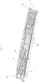
- Fig. 1 shows a vehicle body 1 for a truck, not shown.
- the loading area 16 is designed here as a lifting platform and serves for the transport of motor vehicles, not shown.
- the fall protection 3 and the catwalk 5 can be provided on both sides or only one of the sides of the vehicle body 1.
- Fig. 1 is the fall protection 3 in its transport position. In this position, it is located near the loading area 16.
- Fig. 2 shows the fall protection 3 in the loading position. In this position, it is further away from the loading area 16, whereby more space between the fall protection 3 and the load (here: motor vehicles) is available, which facilitates the opening of the doors of motor vehicles in the example chosen.
- the fall protection 3 has a plurality of uprights 19, which are each mounted in this embodiment about a vertical axis 17 pivotally mounted on the loading area 16. Between the uprights 19 horizontally extending elements (pipes, ropes or the like) are arranged.
- the fall protection 3 extends in this embodiment over the entire length of the loading area 16. Alternatively, along the longitudinal extension of the loading area 16, of course, a plurality of successively arranged fall arresters 3 may be provided. It is also not absolutely necessary to provide the entire longitudinal extent of the loading area 16 with a fall protection 3.
- the catwalk 5 is in the operating state of Fig. 1 in the storage position and is pivoted approximately parallel to the fall protection 3 in the present embodiment.
- Fig. 2 is the catwalk 5 in the use position and covers the area between the fall protection 3 and the loading area 16 substantially.
- the catwalk 5 is mounted in this embodiment about a horizontal axis 18 pivotally mounted on the loading area 16.
- the catwalk 5 is formed in this embodiment as an embossed to increase slip resistance steel construction and extends over the entire length of the loading area 16. Alternatively, along the longitudinal extension of the loading area 16 of course, several, consecutively arranged walkways 5 may be provided. It is also not absolutely necessary to provide the entire longitudinal extent of the loading area 16 with a catwalk 5.
- the Fig. 3a and 3b show rear views of the Fig. 1 or 2.
- Fig. 3a It can be seen that the catwalk 5 in its storage position approximately parallel to Fall protection 3 is located.
- the fall protection 3 is located near the loading area 16.
- Fig. 3b It can be seen that the catwalk 5 is approximately perpendicular to the fall protection 3 in its use position and covers the area between the fall protection device 3 and the loading area 16.
- the fall protection 3 is compared to Fig. 3a furthest away from the loading area 16.
- the Fig. 3c and 3d show the corresponding perspective views.
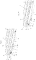
- Fig. 4a-4d show the transition from the operating state of Fig. 1 to that of Fig. 2 .
- the reciprocating movement of the fall arrest device 3 is effected by a movement device 2, which in this exemplary embodiment has a first pivot arm 7 with respect to each post 19, which is pivotable about the vertical axis 17 in each case.
- the first pivot arm 7 is connected on the one hand to the loading area 16 and on the other hand to the fall protection 3, namely to the respective stay 19.
- the adjustment of the catwalk 5 is carried out by an adjusting device 4, which in this embodiment in the region of each post 19 has a second pivot arm 8 which is pivotable about the horizontal axis 18 respectively.
- the second pivot arm 8 is connected on the one hand to the loading area 16 and on the other hand to the catwalk 5.
- the driving of the moving device 2 and the adjusting device 4 is effected by a single motor, which is provided in this embodiment only in the region of a post 19 and a piston-cylinder unit 9, wherein the piston-cylinder unit 9 on the one hand (here with the Piston) with the loading area 16 and on the other hand via a cylinder receiving 20 with the first pivot arm 7 (here with the cylinder) is connected.
- the piston-cylinder unit 9 can be controlled by a control device, not shown. Of course, could be provided per fall protection 3 more than just a motor.
- a mechanical coupling device 6 is provided for coupling the adjusting device 4 and the movement device 2, which in detail in the Fig. 5 is shown.
- Fig. 5 It shows a bevel gear, wherein one of the bevel gears on the first pivot arm 7 and the other of the bevel gears on the second pivot arm 8 is arranged.
- a 1: 1 ratio was chosen for the bevel gear, this is not essential.
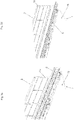
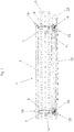
- Fig. 6a and 6b show an advantageous embodiment of the invention, in which the fall protection 3 and the catwalk 5 in a longitudinal extent of the loading area 16 are variable in length (here: telescopic) are formed.
- the fall protection 3 and the catwalk 5 are shown in the state of minimum length.
- the fall protection 3 and the catwalk 5 in the state of maximum length (maximum extended) are shown. Changing the lengths is possible regardless of the operating state (use or storage position and / or transport or loading position).
- the loading area lighting 15 may be provided on both sides or only one of the sides of the vehicle body 1.
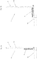
- Fig. 7 shows a second embodiment of the invention in a plan view of the vehicle body 1. To make the hidden by the catwalk 5 construction visible, in this figure, the catwalk 5 was shown transparent (dashed).
- a motor for adjusting or moving the catwalk 5 and the fall protection 3 is provided, which drives a shaft 12, wherein on the shaft 12 worm gears 13 are arranged, which cooperate with teeth 14, wherein the teeth 14 are arranged on the first pivot arms 7.
- the second pivot arms 8 are not arranged directly on the first pivot arms 7 in this embodiment, but they are mechanically or motion-coupled thereto via coupling rods 11. Now turn z. B. the motor, the shaft 12 in a clockwise direction, the first pivot arms 7 via the worm gear 13 and the teeth 14, starting from that position in which the fall protection 3 is in the transport position, pivoted in the direction of that position in which the Fall protection 3 is in the loading position.
- piston-cylinder unit 9 is the in Fig. 7 shown mechanism of motor and shaft 12 used.
- the toothing 14 is in this embodiment, also on the first pivot arm 7 and here is a part of the in Fig. 4 shown bevel gear, which otherwise according to the Fig. 4 is trained. There is no coupling rod 11 is required.
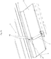
- Fig. 8a, 8b and 8c show in two rear views and a perspective view of an embodiment in which as an alternative to the coupling rod 11 in relation to a movement from the use position in the storage position, a forced operation is provided.
- the first pivot arm 7 is here pivotally mounted on the loading area 16 about a vertical axis 17.
- Fig. 8a or 8c are the fall protection 3 and the catwalk 5 in the loading position or use position.
- the catwalk 5 indicates his outer end to a driver 21 which rests in the loading position of the fall protection 3 on the upright 19 of the fall protection 3.
- Fig. 9a and 9b show an alternative to the arrangement in the Fig. 4a to 4d
- the second pivot arm 8 is driven directly by the piston-cylinder unit 9 and the first pivot arm 7 is moved by the coupling device 6.
Landscapes
- Engineering & Computer Science (AREA)
- Mechanical Engineering (AREA)
- Transportation (AREA)
- Chemical & Material Sciences (AREA)
- Combustion & Propulsion (AREA)
- Health & Medical Sciences (AREA)
- Public Health (AREA)
- Vehicle Cleaning, Maintenance, Repair, Refitting, And Outriggers (AREA)
Description
Die vorliegende Erfindung betrifft einen Fahrzeugaufbau mit den Merkmalen des Oberbegriffs des Anspruchs 1 und ein Fahrzeug mit einem solchen Fahrzeugaufbau.
Ein nicht gattungsgemäßer Fahrzeugaufbau geht aus der
Aus der
Auch bei dem in der
Die
A non-generic vehicle body is from the
From the
Also in the in the
The
In der gattungsgemäßen
Die Druckschriften
The pamphlets
Die
Aufgabe der Erfindung ist die Bereitstellung eines gattungsgemäßen Fahrzeugaufbaus und eines mit einem solchen Fahrzeugaufbau versehenen Fahrzeugs, bei welchen dieses Problem nicht auftritt.The object of the invention is to provide a generic vehicle body and a vehicle provided with such a vehicle body, in which this problem does not occur.
Diese Aufgabe wird durch einen Fahrzeugaufbau mit den Merkmalen des Anspruchs 1 und ein Fahrzeug mit einem solchen Fahrzeugaufbau gelöst. Vorteilhafte Ausführungsformen der Erfindung sind in den abhängigen Ansprüchen definiert.This object is achieved by a vehicle body having the features of
Bei der Erfindung ist vorgesehen, dass die Bewegungsvorrichtung und die Verstellvorrichtung derart miteinander gekoppelt sind, dass bei einer Betätigung der Verstellvorrichtung eine Betätigung der Bewegungsvorrichtung erfolgt oder umgekehrt. Durch die Erfindung genügt ein einziger Betätigungsschritt um sowohl die Bewegungsvorrichtung für die Absturzsicherung als auch die Verstellvorrichtung für den Laufsteg auszulösen. Der Manipulationsaufwand ist gegenüber dem Stand der Technik reduziert.In the case of the invention, it is provided that the movement device and the adjustment device are coupled to one another in such a way that actuation of the movement device takes place upon actuation of the adjustment device or vice versa. By means of the invention, a single actuating step is sufficient to trigger both the movement device for the fall protection and the adjustment device for the catwalk. The manipulation effort is reduced compared to the prior art.
Bevorzugt werden die Bewegungsvorrichtung und die Verstellvorrichtung annähernd gleichzeitig aktiv sein.Preferably, the moving device and the adjusting device will be active approximately simultaneously.
Weitere Vorteile und Einzelheiten der Erfindung werden für mehrere Ausführungsbeispiele anhand der Figuren erläutert. In Bezug auf eines der Ausführungsbeispiele diskutierten Merkmale können auch bei den anderen Ausführungsbeispielen angewandt werden.Further advantages and details of the invention will be explained for several embodiments with reference to FIGS. Features discussed with respect to one of the embodiments may also be applied to the other embodiments.
Es zeigen:
- Fig. 1
- ein erstes Ausführungsbeispiel eines erfindungsgemäßen Fahrzeugaufbaus in einem ersten Betriebszustand in einer perspektivischen Ansicht,
- Fig. 2
- das Ausführungsbeispiel der
Fig. 1 in einem zweiten Betriebszustand in einer perspektivischen Ansicht, - Fig. 3a-3d
- Heckansichten bzw. perspektivische Ansichten zu einem Detail der
Fig. 1 bzw. 2, - Fig. 4a-4d
- eine Detailansicht des Fahrzeugaufbaus der vorangehenden Figuren in unterschiedlichen Betriebszuständen,
- Fig. 5
- eine Detailansicht zu einem Ausführungsbeispiel der mechanischen Koppelungsvorrichtung,
- Fig. 6a,6b
- perspektivische Ansichten zu einem weiteren Ausführungsbeispiel der Erfindung,
- Fig. 7
- ein zweites Ausführungsbeispiel der Erfindung,
- Fig. 8a-8c
- ein drittes Ausführungsbeispiel der Erfindung und
- Fig. 9a,9b
- ein viertes Ausführungsbeispiel der Erfindung.
- Fig. 1
- A first embodiment of a vehicle body according to the invention in a first operating state in a perspective view,
- Fig. 2
- the embodiment of
Fig. 1 in a second operating state in a perspective view, - Fig. 3a-3d
- Rear views or perspective views to a detail of
Fig. 1 or 2, - Fig. 4a-4d
- a detailed view of the vehicle body of the preceding figures in different operating conditions,
- Fig. 5
- a detailed view of an embodiment of the mechanical coupling device,
- Fig. 6a, 6b
- perspective views of a further embodiment of the invention,
- Fig. 7
- A second embodiment of the invention,
- Fig. 8a-8c
- A third embodiment of the invention and
- Fig. 9a, 9b
- A fourth embodiment of the invention.
In
Der Laufsteg 5 befindet sich im Betriebszustand der
Die
Die Abfolge der
Das Hin und Herbewegen der Absturzsicherung 3 erfolgt durch eine Bewegungsvorrichtung 2, die in diesem Ausführungsbeispiel in Bezug auf jeden Steher 19 einen ersten Schwenkarm 7 aufweist, welcher jeweils um die vertikale Achse 17 verschwenkbar ist. Der erste Schwenkarm 7 ist einerseits mit dem Ladebereich 16 und andererseits mit der Absturzsicherung 3 verbunden, nämlich mit dem jeweiligen Steher 19.The reciprocating movement of the
Das Verstellen des Laufsteges 5 erfolgt durch eine Verstellvorrichtung 4, die in diesem Ausführungsbeispiel im Bereich jedes Stehers 19 einen zweiten Schwenkarm 8 aufweist, welcher jeweils um die horizontale Achse 18 verschwenkbar ist. Der zweite Schwenkarm 8 ist einerseits mit dem Ladebereich 16 und andererseits mit dem Laufsteg 5 verbunden.The adjustment of the
Das Antreiben der Bewegungsvorrichtung 2 und der Verstellvorrichtung 4 erfolgt durch einen einzigen Motor, der in diesem Ausführungsbeispiel nur im Bereich eines Stehers 19 vorgesehen ist und eine Kolben-Zylinder-Einheit 9 aufweist, wobei die Kolben-Zylinder-Einheit 9 einerseits (hier mit dem Kolben) mit dem Ladebereich 16 und andererseits über eine Zylinderaufnahme 20 mit dem ersten Schwenkarm 7 (hier mit dem Zylinder) verbunden ist. Die Kolben-Zylinder-Einheit 9 ist durch eine nicht dargestellte Steuereinrichtung ansteuerbar. Natürlich könnte pro Absturzsicherung 3 auch mehr als nur ein Motor vorgesehen sein.The driving of the moving
In diesem Ausführungsbeispiel ist eine mechanische Koppelungsvorrichtung 6 zum Koppeln der Verstellvorrichtung 4 und der Bewegungsvorrichtung 2 vorgesehen, welche im Detail in der
In
In
In
Der Übergang in die Verwahrstellung bzw. die Transportstellung ergibt sich bei Betrachtung der
Die
Ebenfalls erkennbar ist eine Ladebereichbeleuchtung 15 an der Oberkante der Absturzsicherung 3, welche den Vorteil hat, den Ladebereich 16 von den Seiten zu beleuchten und damit beim Be- bzw. Entladen nicht zu blenden. Die Ladebereichbeleuchtung 15 kann auf beiden Seiten oder nur einer der Seiten des Fahrzeugaufbaus 1 vorgesehen sein.Also recognizable is a
Es ist ein Motor (hier: Elektro-oder Hydraulikmotor 22) zum Verstellen bzw. Bewegen des Laufstegs 5 bzw. der Absturzsicherung 3 vorgesehen, der eine Welle 12 antreibt, wobei an der Welle 12 Schneckengetriebe 13 angeordnet sind, die mit Verzahnungen 14 zusammenwirken, wobei die Verzahnungen 14 an den ersten Schwenkarmen 7 angeordnet sind. Die zweiten Schwenkarme 8 sind in diesem Ausführungsbeispiel nicht unmittelbar an den ersten Schwenkarmen 7 angeordnet, sie sind jedoch mit diesen über Koppelstangen 11 mechanisch bzw. bewegungsgekoppelt. Dreht nun z. B. der Motor die Welle 12 im Uhrzeigersinn, so werden die ersten Schwenkarme 7 über die Schneckengetriebe 13 und die Verzahnungen 14 ausgehend von jener Stellung, bei welcher sich die Absturzsicherung 3 in der Transportstellung befindet, in Richtung jener Stellung verschwenkt, bei welcher sich die Absturzsicherung 3 in der Ladestellung befindet. Gleichzeitig verschwenkt der Laufsteg 5 durch die Koppelstange 11 und die zweiten Schwenkarme 8 aus der Verwahrstellung in die Nutzstellung. Dreht der Motor die Welle 12 in die andere Richtung (hier: gegen den Uhrzeigersinn), bewegt sich die Absturzsicherung 3 von der Ladestellung in die Transportstellung und der Laufsteg 5 bewegt sich aus der Nutzstellung in die Verwahrstellung.There is a motor (here: electric or hydraulic motor 22) for adjusting or moving the
Es ist auch eine Mischform der Ausführungsbeispiele der
Alternativ zu der in den Fig. gezeigten mechanischen Koppelungsvorrichtung 6 könnte auch eine rein elektronische Koppelung (Synchronisierung) der Bewegungsvorrichtung 2 und der Verstellvorrichtung 4 erfolgen, vor allem, wenn diese jeweils einen eigenen Motor aufweisen.As an alternative to the
- 11
- Fahrzeugaufbauvehicle body
- 22
- Bewegungsvorrichtungmover
- 33
- Absturzsicherungfall Protection
- 44
- Verstellvorrichtungadjustment
- 55
- Laufstegcatwalk
- 66
- Mechanische KoppelungsvorrichtungMechanical coupling device
- 77
- Erster SchwenkarmFirst swivel arm
- 88th
- Zweiter SchwenkarmSecond swivel arm
- 99
- Kolben-Zylinder-EinheitPiston-cylinder unit
- 1010
- Schneckenantriebscrew drive
- 1111
- Koppelstangecoupling rod
- 1212
- Wellewave
- 1313
- Schneckengetriebeworm gear
- 1414
- Verzahnunggearing
- 1515
- LadebereichbeleuchtungCargo area lighting
- 1616
- Ladebereichloading area
- 1717
- Vertikale AchseVertical axis
- 1818
- Horizontale AchseHorizontal axis
- 1919
- Steherstayer
- 2020
- Zylinderaufnahmecylinder intake
- 2121
- Mitnehmertakeaway
- 2222
- Elektro- oder HydraulikmotorElectric or hydraulic motor
Claims (12)
- A vehicle structure (1) having a load region (16) which can be safeguarded by a fall protection means (3), wherein the fall protection means (3) is reciprocable by a movement device (2) between a transport position and a loading position, and a walkway (5) displaceable by an adjusting device (4) between a storage position and a use position, wherein the movement device (2) and the adjusting device (4) are coupled together in such a way that upon actuation of the adjusting device (4) actuation of the movement device (2) is effected or vice-versa, characterised in that the adjusting device (4) has at least one second pivot arm (8) - which is preferably pivotable about a horizontal axis (18) - and which is connected on the one hand to the walkway (5) and on the other hand either to the load region (16) or to a first pivot arm (7) of the movement device (2).
- A vehicle structure according to claim 1 wherein the movement device (2) has at least one first pivot arm (7) - which is preferably pivotable about a vertical axis (17) - and which is connected on the one hand to the load region (16) and on the other hand to the fall protection means (3).
- A vehicle structure according to at least one of the preceding claims wherein the movement device (2) and/or the adjusting device (4) is or are motor-driven.
- A vehicle structure according to claim 3 wherein there is provided a motor for the movement device (2) and the adjusting device (4) in the form of a hydraulic piston-cylinder unit (9) or in the form of a worm drive (10).
- A vehicle structure according to at least one of the preceding claims wherein there is provided a mechanical coupling device (6) for coupling the adjusting device (4) and the movement device (2).
- A vehicle structure according to claim 5 wherein the mechanical coupling device (6) is in the form of a mechanical transmission, preferably in the form of a bevel gear transmission.
- A vehicle structure according to claim 5 wherein the mechanical coupling device (6) is in the form of a coupling bar (11).
- A vehicle structure according to claim 5 wherein the mechanical coupling device (6) is in the form of an entrainment means (21).
- A vehicle structure according to at least one of the preceding claims wherein the fall protection means (3) and/or the walkway (5) extend over an entire length of the load region (16).
- A vehicle structure according to at least one of the preceding claims wherein the fall protection means (3) and/or the walkway (5) are adapted to be variable in length, preferably telescopically, in a longitudinal extent of the load region (16).
- A vehicle structure according to at least one of the preceding claims wherein there is provided a load region lighting means (15) which is arranged - preferably at an upper edge of the fall protection means (3) - on the fall protection means (3).
- A vehicle, in particular a truck or a trailer for a road vehicle, comprising a vehicle structure (1) according to at least one of the preceding claims.
Applications Claiming Priority (1)
| Application Number | Priority Date | Filing Date | Title |
|---|---|---|---|
| ATA50629/2015A AT516739B1 (en) | 2015-07-17 | 2015-07-17 | vehicle body |
Publications (2)
| Publication Number | Publication Date |
|---|---|
| EP3118058A1 EP3118058A1 (en) | 2017-01-18 |
| EP3118058B1 true EP3118058B1 (en) | 2018-09-19 |
Family
ID=56119327
Family Applications (1)
| Application Number | Title | Priority Date | Filing Date |
|---|---|---|---|
| EP16172894.4A Active EP3118058B1 (en) | 2015-07-17 | 2016-06-03 | Vehicle superstructure |
Country Status (2)
| Country | Link |
|---|---|
| EP (1) | EP3118058B1 (en) |
| AT (1) | AT516739B1 (en) |
Cited By (1)
| Publication number | Priority date | Publication date | Assignee | Title |
|---|---|---|---|---|
| WO2022010405A1 (en) * | 2020-07-06 | 2022-01-13 | Väderstad Holding Ab | Agricultural implement with folding operator platform and method of folding an operator platform |
Families Citing this family (3)
| Publication number | Priority date | Publication date | Assignee | Title |
|---|---|---|---|---|
| NL1043072B9 (en) * | 2018-11-06 | 2020-07-22 | Struijk Bastiaan | Trailer Load / Unload Safety System plus |
| FR3112108B1 (en) * | 2020-07-06 | 2022-06-17 | Cvinnov | load-carrying assembly for rolling machine and rolling machine equipped with such a load-carrying assembly |
| IT202200018066A1 (en) * | 2022-09-02 | 2022-12-02 | Rolfo Spa | Anti-fall system and vehicle for transporting motor vehicles equipped with such an anti-fall system |
Family Cites Families (8)
| Publication number | Priority date | Publication date | Assignee | Title |
|---|---|---|---|---|
| US4613155A (en) * | 1984-12-03 | 1986-09-23 | Greenwood William P | Safety platform assembly for sanding trucks |
| US6598704B2 (en) * | 2000-08-03 | 2003-07-29 | David A. Hansen | Truck catwalk system |
| US20100230210A1 (en) * | 2009-03-12 | 2010-09-16 | Hanks Gilbert A | Retracting platform |
| GB0904835D0 (en) * | 2009-03-20 | 2009-05-06 | Caddick Carl | Trailersafe |
| FR2962953B1 (en) | 2010-07-26 | 2012-08-24 | Lohr Ind | LATERAL RETRACTABLE EXTENSION ATTACHED TO AT LEAST ONE LOADING PLAN OF A CARRIER VEHICLE |
| LT2619033T (en) | 2010-09-22 | 2019-10-25 | Rolfo Spa | Fall-preventing system, particularly for vehicle- transporting trucks |
| GB2488831A (en) * | 2011-03-10 | 2012-09-12 | Stephen John Howard | A fall prevention system for a flatbed vehicle |
| US20120318178A1 (en) * | 2011-06-16 | 2012-12-20 | Christopher Hanks | Folding platform |
-
2015
- 2015-07-17 AT ATA50629/2015A patent/AT516739B1/en active
-
2016
- 2016-06-03 EP EP16172894.4A patent/EP3118058B1/en active Active
Non-Patent Citations (1)
| Title |
|---|
| None * |
Cited By (1)
| Publication number | Priority date | Publication date | Assignee | Title |
|---|---|---|---|---|
| WO2022010405A1 (en) * | 2020-07-06 | 2022-01-13 | Väderstad Holding Ab | Agricultural implement with folding operator platform and method of folding an operator platform |
Also Published As
| Publication number | Publication date |
|---|---|
| AT516739B1 (en) | 2016-08-15 |
| AT516739A4 (en) | 2016-08-15 |
| EP3118058A1 (en) | 2017-01-18 |
Similar Documents
| Publication | Publication Date | Title |
|---|---|---|
| EP3118058B1 (en) | Vehicle superstructure | |
| EP3126268B1 (en) | Lifting device for a truck for emptying waste containers | |
| EP3147160A2 (en) | Storage structure for a commercial vehicle, in particular a heavy goods vehicle | |
| DE2620683B2 (en) | Entrance arrangement for a local transport vehicle, in particular a rail vehicle | |
| WO1997034793A1 (en) | Side wall for a vehicle body | |
| DE2754009A1 (en) | VEHICLE FOR TRANSPORTING LOADS | |
| DE102009033917A1 (en) | Vehicle with swing-out mast arm construction | |
| AT501549B1 (en) | FOOT LEVELS DRIVE | |
| WO2003097411A1 (en) | Loading base for a vehicle and loading device | |
| DE69516819T2 (en) | Loading device for vehicles and vehicles provided with the same | |
| DE2138674A1 (en) | LOADING DEVICE FOR TRUCKS | |
| EP2248702B1 (en) | Lifting device | |
| DE102015207799A1 (en) | Underride protection device with adjusting device and vehicle comprising such an underrun protection device | |
| EP1848603B1 (en) | Hard top | |
| EP1354759A1 (en) | Extendable loading platform | |
| EP0738649B1 (en) | Sidewall for vehicles | |
| EP0992396A2 (en) | Unloading unit for trailer | |
| EP0253263B1 (en) | Vehicle with van body and lifting mechanism | |
| EP0644083A1 (en) | Stowage compartment for camping vehicle | |
| DE102010018966A1 (en) | Robotic gripper and handling robot | |
| DE3941348C2 (en) | ||
| EP2489552B1 (en) | Motor vehicle with a rear view mirror | |
| DE202014101349U1 (en) | Self-propelled roller compactor | |
| DE29611565U1 (en) | Motor vehicle with bulk material trough | |
| AT402723B (en) | Side wall for the body of a vehicle |
Legal Events
| Date | Code | Title | Description |
|---|---|---|---|
| PUAI | Public reference made under article 153(3) epc to a published international application that has entered the european phase |
Free format text: ORIGINAL CODE: 0009012 |
|
| STAA | Information on the status of an ep patent application or granted ep patent |
Free format text: STATUS: THE APPLICATION HAS BEEN PUBLISHED |
|
| AK | Designated contracting states |
Kind code of ref document: A1 Designated state(s): AL AT BE BG CH CY CZ DE DK EE ES FI FR GB GR HR HU IE IS IT LI LT LU LV MC MK MT NL NO PL PT RO RS SE SI SK SM TR |
|
| AX | Request for extension of the european patent |
Extension state: BA ME |
|
| STAA | Information on the status of an ep patent application or granted ep patent |
Free format text: STATUS: REQUEST FOR EXAMINATION WAS MADE |
|
| 17P | Request for examination filed |
Effective date: 20170404 |
|
| RBV | Designated contracting states (corrected) |
Designated state(s): AL AT BE BG CH CY CZ DE DK EE ES FI FR GB GR HR HU IE IS IT LI LT LU LV MC MK MT NL NO PL PT RO RS SE SI SK SM TR |
|
| GRAP | Despatch of communication of intention to grant a patent |
Free format text: ORIGINAL CODE: EPIDOSNIGR1 |
|
| STAA | Information on the status of an ep patent application or granted ep patent |
Free format text: STATUS: GRANT OF PATENT IS INTENDED |
|
| INTG | Intention to grant announced |
Effective date: 20180615 |
|
| GRAS | Grant fee paid |
Free format text: ORIGINAL CODE: EPIDOSNIGR3 |
|
| GRAA | (expected) grant |
Free format text: ORIGINAL CODE: 0009210 |
|
| STAA | Information on the status of an ep patent application or granted ep patent |
Free format text: STATUS: THE PATENT HAS BEEN GRANTED |
|
| AK | Designated contracting states |
Kind code of ref document: B1 Designated state(s): AL AT BE BG CH CY CZ DE DK EE ES FI FR GB GR HR HU IE IS IT LI LT LU LV MC MK MT NL NO PL PT RO RS SE SI SK SM TR |
|
| REG | Reference to a national code |
Ref country code: GB Ref legal event code: FG4D Free format text: NOT ENGLISH |
|
| REG | Reference to a national code |
Ref country code: CH Ref legal event code: EP |
|
| REG | Reference to a national code |
Ref country code: DE Ref legal event code: R096 Ref document number: 502016001997 Country of ref document: DE |
|
| REG | Reference to a national code |
Ref country code: AT Ref legal event code: REF Ref document number: 1042873 Country of ref document: AT Kind code of ref document: T Effective date: 20181015 |
|
| REG | Reference to a national code |
Ref country code: IE Ref legal event code: FG4D Free format text: LANGUAGE OF EP DOCUMENT: GERMAN |
|
| REG | Reference to a national code |
Ref country code: NL Ref legal event code: FP |
|
| PG25 | Lapsed in a contracting state [announced via postgrant information from national office to epo] |
Ref country code: FI Free format text: LAPSE BECAUSE OF FAILURE TO SUBMIT A TRANSLATION OF THE DESCRIPTION OR TO PAY THE FEE WITHIN THE PRESCRIBED TIME-LIMIT Effective date: 20180919 Ref country code: NO Free format text: LAPSE BECAUSE OF FAILURE TO SUBMIT A TRANSLATION OF THE DESCRIPTION OR TO PAY THE FEE WITHIN THE PRESCRIBED TIME-LIMIT Effective date: 20181219 Ref country code: RS Free format text: LAPSE BECAUSE OF FAILURE TO SUBMIT A TRANSLATION OF THE DESCRIPTION OR TO PAY THE FEE WITHIN THE PRESCRIBED TIME-LIMIT Effective date: 20180919 Ref country code: BG Free format text: LAPSE BECAUSE OF FAILURE TO SUBMIT A TRANSLATION OF THE DESCRIPTION OR TO PAY THE FEE WITHIN THE PRESCRIBED TIME-LIMIT Effective date: 20181219 Ref country code: SE Free format text: LAPSE BECAUSE OF FAILURE TO SUBMIT A TRANSLATION OF THE DESCRIPTION OR TO PAY THE FEE WITHIN THE PRESCRIBED TIME-LIMIT Effective date: 20180919 Ref country code: GR Free format text: LAPSE BECAUSE OF FAILURE TO SUBMIT A TRANSLATION OF THE DESCRIPTION OR TO PAY THE FEE WITHIN THE PRESCRIBED TIME-LIMIT Effective date: 20181220 Ref country code: LT Free format text: LAPSE BECAUSE OF FAILURE TO SUBMIT A TRANSLATION OF THE DESCRIPTION OR TO PAY THE FEE WITHIN THE PRESCRIBED TIME-LIMIT Effective date: 20180919 |
|
| REG | Reference to a national code |
Ref country code: LT Ref legal event code: MG4D |
|
| PG25 | Lapsed in a contracting state [announced via postgrant information from national office to epo] |
Ref country code: AL Free format text: LAPSE BECAUSE OF FAILURE TO SUBMIT A TRANSLATION OF THE DESCRIPTION OR TO PAY THE FEE WITHIN THE PRESCRIBED TIME-LIMIT Effective date: 20180919 Ref country code: LV Free format text: LAPSE BECAUSE OF FAILURE TO SUBMIT A TRANSLATION OF THE DESCRIPTION OR TO PAY THE FEE WITHIN THE PRESCRIBED TIME-LIMIT Effective date: 20180919 Ref country code: HR Free format text: LAPSE BECAUSE OF FAILURE TO SUBMIT A TRANSLATION OF THE DESCRIPTION OR TO PAY THE FEE WITHIN THE PRESCRIBED TIME-LIMIT Effective date: 20180919 |
|
| PG25 | Lapsed in a contracting state [announced via postgrant information from national office to epo] |
Ref country code: IS Free format text: LAPSE BECAUSE OF FAILURE TO SUBMIT A TRANSLATION OF THE DESCRIPTION OR TO PAY THE FEE WITHIN THE PRESCRIBED TIME-LIMIT Effective date: 20190119 Ref country code: ES Free format text: LAPSE BECAUSE OF FAILURE TO SUBMIT A TRANSLATION OF THE DESCRIPTION OR TO PAY THE FEE WITHIN THE PRESCRIBED TIME-LIMIT Effective date: 20180919 Ref country code: PL Free format text: LAPSE BECAUSE OF FAILURE TO SUBMIT A TRANSLATION OF THE DESCRIPTION OR TO PAY THE FEE WITHIN THE PRESCRIBED TIME-LIMIT Effective date: 20180919 Ref country code: CZ Free format text: LAPSE BECAUSE OF FAILURE TO SUBMIT A TRANSLATION OF THE DESCRIPTION OR TO PAY THE FEE WITHIN THE PRESCRIBED TIME-LIMIT Effective date: 20180919 Ref country code: RO Free format text: LAPSE BECAUSE OF FAILURE TO SUBMIT A TRANSLATION OF THE DESCRIPTION OR TO PAY THE FEE WITHIN THE PRESCRIBED TIME-LIMIT Effective date: 20180919 Ref country code: EE Free format text: LAPSE BECAUSE OF FAILURE TO SUBMIT A TRANSLATION OF THE DESCRIPTION OR TO PAY THE FEE WITHIN THE PRESCRIBED TIME-LIMIT Effective date: 20180919 |
|
| PG25 | Lapsed in a contracting state [announced via postgrant information from national office to epo] |
Ref country code: SM Free format text: LAPSE BECAUSE OF FAILURE TO SUBMIT A TRANSLATION OF THE DESCRIPTION OR TO PAY THE FEE WITHIN THE PRESCRIBED TIME-LIMIT Effective date: 20180919 Ref country code: SK Free format text: LAPSE BECAUSE OF FAILURE TO SUBMIT A TRANSLATION OF THE DESCRIPTION OR TO PAY THE FEE WITHIN THE PRESCRIBED TIME-LIMIT Effective date: 20180919 Ref country code: PT Free format text: LAPSE BECAUSE OF FAILURE TO SUBMIT A TRANSLATION OF THE DESCRIPTION OR TO PAY THE FEE WITHIN THE PRESCRIBED TIME-LIMIT Effective date: 20190119 |
|
| REG | Reference to a national code |
Ref country code: DE Ref legal event code: R097 Ref document number: 502016001997 Country of ref document: DE |
|
| PLBE | No opposition filed within time limit |
Free format text: ORIGINAL CODE: 0009261 |
|
| STAA | Information on the status of an ep patent application or granted ep patent |
Free format text: STATUS: NO OPPOSITION FILED WITHIN TIME LIMIT |
|
| PG25 | Lapsed in a contracting state [announced via postgrant information from national office to epo] |
Ref country code: DK Free format text: LAPSE BECAUSE OF FAILURE TO SUBMIT A TRANSLATION OF THE DESCRIPTION OR TO PAY THE FEE WITHIN THE PRESCRIBED TIME-LIMIT Effective date: 20180919 |
|
| 26N | No opposition filed |
Effective date: 20190620 |
|
| PG25 | Lapsed in a contracting state [announced via postgrant information from national office to epo] |
Ref country code: SI Free format text: LAPSE BECAUSE OF FAILURE TO SUBMIT A TRANSLATION OF THE DESCRIPTION OR TO PAY THE FEE WITHIN THE PRESCRIBED TIME-LIMIT Effective date: 20180919 |
|
| PG25 | Lapsed in a contracting state [announced via postgrant information from national office to epo] |
Ref country code: MC Free format text: LAPSE BECAUSE OF FAILURE TO SUBMIT A TRANSLATION OF THE DESCRIPTION OR TO PAY THE FEE WITHIN THE PRESCRIBED TIME-LIMIT Effective date: 20180919 |
|
| REG | Reference to a national code |
Ref country code: CH Ref legal event code: PL |
|
| REG | Reference to a national code |
Ref country code: BE Ref legal event code: MM Effective date: 20190630 |
|
| PG25 | Lapsed in a contracting state [announced via postgrant information from national office to epo] |
Ref country code: TR Free format text: LAPSE BECAUSE OF FAILURE TO SUBMIT A TRANSLATION OF THE DESCRIPTION OR TO PAY THE FEE WITHIN THE PRESCRIBED TIME-LIMIT Effective date: 20180919 |
|
| PG25 | Lapsed in a contracting state [announced via postgrant information from national office to epo] |
Ref country code: IE Free format text: LAPSE BECAUSE OF NON-PAYMENT OF DUE FEES Effective date: 20190603 |
|
| PG25 | Lapsed in a contracting state [announced via postgrant information from national office to epo] |
Ref country code: BE Free format text: LAPSE BECAUSE OF NON-PAYMENT OF DUE FEES Effective date: 20190630 Ref country code: LU Free format text: LAPSE BECAUSE OF NON-PAYMENT OF DUE FEES Effective date: 20190603 Ref country code: LI Free format text: LAPSE BECAUSE OF NON-PAYMENT OF DUE FEES Effective date: 20190630 Ref country code: CH Free format text: LAPSE BECAUSE OF NON-PAYMENT OF DUE FEES Effective date: 20190630 |
|
| GBPC | Gb: european patent ceased through non-payment of renewal fee |
Effective date: 20200603 |
|
| PG25 | Lapsed in a contracting state [announced via postgrant information from national office to epo] |
Ref country code: GB Free format text: LAPSE BECAUSE OF NON-PAYMENT OF DUE FEES Effective date: 20200603 |
|
| PG25 | Lapsed in a contracting state [announced via postgrant information from national office to epo] |
Ref country code: CY Free format text: LAPSE BECAUSE OF FAILURE TO SUBMIT A TRANSLATION OF THE DESCRIPTION OR TO PAY THE FEE WITHIN THE PRESCRIBED TIME-LIMIT Effective date: 20180919 |
|
| PG25 | Lapsed in a contracting state [announced via postgrant information from national office to epo] |
Ref country code: MT Free format text: LAPSE BECAUSE OF FAILURE TO SUBMIT A TRANSLATION OF THE DESCRIPTION OR TO PAY THE FEE WITHIN THE PRESCRIBED TIME-LIMIT Effective date: 20180919 Ref country code: HU Free format text: LAPSE BECAUSE OF FAILURE TO SUBMIT A TRANSLATION OF THE DESCRIPTION OR TO PAY THE FEE WITHIN THE PRESCRIBED TIME-LIMIT; INVALID AB INITIO Effective date: 20160603 |
|
| PG25 | Lapsed in a contracting state [announced via postgrant information from national office to epo] |
Ref country code: MK Free format text: LAPSE BECAUSE OF FAILURE TO SUBMIT A TRANSLATION OF THE DESCRIPTION OR TO PAY THE FEE WITHIN THE PRESCRIBED TIME-LIMIT Effective date: 20180919 |
|
| REG | Reference to a national code |
Ref country code: AT Ref legal event code: MM01 Ref document number: 1042873 Country of ref document: AT Kind code of ref document: T Effective date: 20210603 |
|
| PG25 | Lapsed in a contracting state [announced via postgrant information from national office to epo] |
Ref country code: AT Free format text: LAPSE BECAUSE OF NON-PAYMENT OF DUE FEES Effective date: 20210603 |
|
| PGFP | Annual fee paid to national office [announced via postgrant information from national office to epo] |
Ref country code: IT Payment date: 20230626 Year of fee payment: 8 |
|
| PGFP | Annual fee paid to national office [announced via postgrant information from national office to epo] |
Ref country code: DE Payment date: 20240627 Year of fee payment: 9 |
|
| PGFP | Annual fee paid to national office [announced via postgrant information from national office to epo] |
Ref country code: NL Payment date: 20240625 Year of fee payment: 9 |
|
| PGFP | Annual fee paid to national office [announced via postgrant information from national office to epo] |
Ref country code: FR Payment date: 20240628 Year of fee payment: 9 |