EP3117873A1 - Oxygen sensing for fuel tank inerting system - Google Patents
Oxygen sensing for fuel tank inerting system Download PDFInfo
- Publication number
- EP3117873A1 EP3117873A1 EP16179424.3A EP16179424A EP3117873A1 EP 3117873 A1 EP3117873 A1 EP 3117873A1 EP 16179424 A EP16179424 A EP 16179424A EP 3117873 A1 EP3117873 A1 EP 3117873A1
- Authority
- EP
- European Patent Office
- Prior art keywords
- air
- oxygen
- air separation
- nitrogen
- enriched
- Prior art date
- Legal status (The legal status is an assumption and is not a legal conclusion. Google has not performed a legal analysis and makes no representation as to the accuracy of the status listed.)
- Granted
Links
Images

Classifications
-
- B—PERFORMING OPERATIONS; TRANSPORTING
- B01—PHYSICAL OR CHEMICAL PROCESSES OR APPARATUS IN GENERAL
- B01D—SEPARATION
- B01D53/00—Separation of gases or vapours; Recovering vapours of volatile solvents from gases; Chemical or biological purification of waste gases, e.g. engine exhaust gases, smoke, fumes, flue gases, aerosols
- B01D53/22—Separation of gases or vapours; Recovering vapours of volatile solvents from gases; Chemical or biological purification of waste gases, e.g. engine exhaust gases, smoke, fumes, flue gases, aerosols by diffusion
-
- B—PERFORMING OPERATIONS; TRANSPORTING
- B64—AIRCRAFT; AVIATION; COSMONAUTICS
- B64D—EQUIPMENT FOR FITTING IN OR TO AIRCRAFT; FLIGHT SUITS; PARACHUTES; ARRANGEMENT OR MOUNTING OF POWER PLANTS OR PROPULSION TRANSMISSIONS IN AIRCRAFT
- B64D37/00—Arrangements in connection with fuel supply for power plant
- B64D37/32—Safety measures not otherwise provided for, e.g. preventing explosive conditions
-
- B—PERFORMING OPERATIONS; TRANSPORTING
- B01—PHYSICAL OR CHEMICAL PROCESSES OR APPARATUS IN GENERAL
- B01D—SEPARATION
- B01D63/00—Apparatus in general for separation processes using semi-permeable membranes
-
- B—PERFORMING OPERATIONS; TRANSPORTING
- B01—PHYSICAL OR CHEMICAL PROCESSES OR APPARATUS IN GENERAL
- B01D—SEPARATION
- B01D53/00—Separation of gases or vapours; Recovering vapours of volatile solvents from gases; Chemical or biological purification of waste gases, e.g. engine exhaust gases, smoke, fumes, flue gases, aerosols
- B01D53/22—Separation of gases or vapours; Recovering vapours of volatile solvents from gases; Chemical or biological purification of waste gases, e.g. engine exhaust gases, smoke, fumes, flue gases, aerosols by diffusion
- B01D2053/221—Devices
-
- B—PERFORMING OPERATIONS; TRANSPORTING
- B01—PHYSICAL OR CHEMICAL PROCESSES OR APPARATUS IN GENERAL
- B01D—SEPARATION
- B01D2256/00—Main component in the product gas stream after treatment
- B01D2256/10—Nitrogen
-
- B—PERFORMING OPERATIONS; TRANSPORTING
- B01—PHYSICAL OR CHEMICAL PROCESSES OR APPARATUS IN GENERAL
- B01D—SEPARATION
- B01D2257/00—Components to be removed
- B01D2257/10—Single element gases other than halogens
- B01D2257/104—Oxygen
-
- B—PERFORMING OPERATIONS; TRANSPORTING
- B01—PHYSICAL OR CHEMICAL PROCESSES OR APPARATUS IN GENERAL
- B01D—SEPARATION
- B01D2259/00—Type of treatment
- B01D2259/45—Gas separation or purification devices adapted for specific applications
- B01D2259/4566—Gas separation or purification devices adapted for specific applications for use in transportation means
- B01D2259/4575—Gas separation or purification devices adapted for specific applications for use in transportation means in aeroplanes or space ships
-
- B—PERFORMING OPERATIONS; TRANSPORTING
- B01—PHYSICAL OR CHEMICAL PROCESSES OR APPARATUS IN GENERAL
- B01D—SEPARATION
- B01D2313/00—Details relating to membrane modules or apparatus
- B01D2313/60—Specific sensors or sensor arrangements
-
- B—PERFORMING OPERATIONS; TRANSPORTING
- B01—PHYSICAL OR CHEMICAL PROCESSES OR APPARATUS IN GENERAL
- B01D—SEPARATION
- B01D2313/00—Details relating to membrane modules or apparatus
- B01D2313/90—Additional auxiliary systems integrated with the module or apparatus
- B01D2313/903—Integrated control or detection device
Definitions
- This disclosure relates to air separation systems for aircraft, and more specifically to an oxygen sensor for a nitrogen generation system.
- Aircraft fuel tanks and containers can contain potentially combustible combinations of oxygen, fuel vapors, and ignition sources.
- the ullage of fuel tanks and containers is filled with air with high nitrogen concentration, or nitrogen-enriched air (NEA).
- NGS nitrogen generation system
- a nitrogen generation system (NGS) is commonly used to produce NEA for inerting fuel tanks and containers.
- An air separation module (ASM) in the NGS separates ambient air into NEA, which is directed to fuel tanks and containers, and oxygen-enriched air (OEA), which is rejected overboard.
- the ASM typically includes a polymeric membrane for separating ambient air into NEA and OEA.
- an oxygen sensor can be used to ensure that the oxygen concentration in the NEA remains below a prescribed level in order to reduce risk of explosion in fuel tanks and containers.
- the oxygen sensor is fed by a small slip gas flow from the NEA flowing out of the ASM to the fuel tanks and containers. Once the slip gas flow passes through the oxygen sensor so that the oxygen sensor measures the oxygen concentration in the NEA, the slip gas flow is rejected overboard. Positioning an oxygen sensor in a slip gas flow stream therefore results in a loss of NEA, which could otherwise be used for fuel tank and container inerting. Additionally, the oxygen sensor and slip gas flow take up additional room, which results in the NGS taking up additional space within the aircraft.
- an air separation system includes an air separation module configured to receive feed air and separate the feed air into nitrogen-enriched air and oxygen-enriched air.
- the air separation module includes an inlet header, an outlet header, and an oxygen sensor located in the outlet header and configured to sense a concentration of oxygen in the nitrogen-enriched air.
- an air separation system in another embodiment, includes an air separation manifold configured to receive feed air and separate the feed air into nitrogen-enriched air and oxygen-enriched air.
- the air separation manifold includes air separation modules, and each of the air separation modules includes an inlet header, an outlet header, and an oxygen sensor located in the outlet header and configured to sense a concentration of oxygen in the nitrogen-enriched air.
- a method for sensing oxygen concentration in an air separation system includes flowing feed air into an air separation module.
- the air separation module includes an inlet header, an outlet header, and an oxygen sensor located in the outlet header.
- the method further includes separating the feed air into nitrogen-enriched air and oxygen-enriched air in the air separation module, flowing the nitrogen-enriched air through the oxygen sensor located in the outlet header of the air separation module, and sensing a concentration of oxygen in the nitrogen-enriched air with the oxygen sensor.
- the present disclosure relates to an air separation system, specifically a nitrogen generation system (NGS), for generating air with high nitrogen concentration (nitrogen-enriched air).
- NGS nitrogen generation system
- An air separation module (ASM) in the NGS separates feed air into nitrogen-enriched air (NEA) and oxygen-enriched air (OEA).
- the oxygen concentration in the NEA is measured using an oxygen sensor to ensure that the oxygen concentration in the NEA remains below a prescribed level.
- the oxygen sensor is located in the outlet header of the ASM, which eliminates the need for a slip gas flow and allows all of the NEA generated by the ASM to be routed to fuel tanks and containers for inerting.
- each ASM has an oxygen sensor in the outlet header. This allows for monitoring of each ASM with a corresponding oxygen sensor to determine if and when the membrane of each ASM requires replacement.
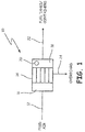
- FIG. 1 is a schematic diagram of NGS 10.
- NGS 10 includes feed air line 12 and ASM 14.
- ASM 14 includes inlet header 16 and outlet header 18 with oxygen sensor 20.
- NGS 10 also includes NEA line 22, and OEA line 24.
- ASM 14 receives feed air through feed air line 12 and separates the feed air into NEA and OEA.
- the NEA leaves ASM 14 through NEA line 22 and is routed to fuel tanks and containers for inerting.
- the OEA leaves ASM 14 through OEA line 24 and is typically rejected overboard.
- ASM 14 can be a membrane-based ASM with a membrane made of a polymer such as poly(1-trimethylsilyl-1-propyne), Teflon, silicone rubber, poly(4-methyl-1-pentene), poly(phenylene oxide), ethyl cellulose, polyimide, polysulfone, polyaramide, tetrabromo bis polycarbonate, or combinations thereof.
- feed air enters ASM 14 the feed air passes through inlet header 16 and enters the membrane of ASM 14.
- Inlet header 16 is an empty space within ASM 14 where the flow of feed air is distributed prior to entering the membrane of ASM 14.
- the membrane separates the feed air into NEA and OEA, and the NEA flows through outlet header 18 into NEA line 22.
- Outlet header 18 is an empty space within ASM 14 where the NEA that is separated in the membrane of ASM 14 is combined prior to distribution to fuel tanks and containers through NEA line 22.
- Oxygen sensor 20 is located in outlet header 18.
- Oxygen sensor 20 can be integral to outlet header 18 and ASM 14.
- oxygen sensor 20 can be removable so that oxygen sensor 20 can be replaced without having to remove ASM 14 from NGS 10.
- Oxygen sensor 20 can be a metal oxide based sensor or any other suitable material for sensing oxygen concentration.
- Oxygen sensor 20 determines the concentration of oxygen in the NEA leaving ASM 14 through outlet header 18 in order to ensure that the oxygen concentration in the NEA remains below a prescribed level.
- the oxygen concentration sensed by oxygen sensor 20 can be communicated to a control system.
- the control system can adjust the flow rate and temperature of feed air flowing through ASM 14 in order to change the oxygen concentration in the NEA to a desired level.
- the oxygen concentration in the NEA should remain below 12%.
- For military aircraft, the oxygen concentration in the NEA should remain below 8%.
- NGS 10 is advantageous, because oxygen sensor 20 is located in outlet header 18 of ASM 14. This eliminates the need for a slip gas flow from NEA line 22 to an oxygen sensor, and allows all of the NEA generated by ASM 14 to be routed through NEA line 22 to fuel tanks and containers for inerting. Placing oxygen sensor 20 in outlet header 18 also saves space within NGS 10, because it eliminates the need for space for a separate flow line and oxygen sensor outside of ASM 14. This allows NGS 10 to be more compact and take up less space within an aircraft.
- FIG. 2 is a schematic diagram of NGS 100, another embodiment of NGS 10 of FIG. 1 .
- NGS 100 includes feed air line 112 and air separation manifold 114.
- Air separation manifold 114 includes ASM 116, ASM 118, and ASM 120.
- ASM 116 includes inlet header 122 and outlet header 124 with oxygen sensor 126.
- ASM 118 includes inlet header 128 and outlet header 130 with oxygen sensor 132.
- ASM 120 includes inlet header 134 and outlet header 136 with oxygen sensor 138.
- NGS 100 functions similarly to NGS 10 in FIG. 1 , except NGS 100 has air separation manifold 114 with ASMs 116, 118, and 120, instead of ASM 14.
- ASM manifold 114 receives feed air through feed air line 112 and distributes the feed air to ASMs 116, 118, and 120.
- ASMs 116, 118 and 120 separate the feed air into NEA and OEA.
- the NEA leaves ASMs 116, 118, and 120 and is combined within air separation manifold 114.
- the NEA leaves air separation manifold 114 through NEA line 142 and is routed to fuel tanks and containers for inerting.
- the OEA is also combined within air separation manifold 114.
- the OEA leaves air separation manifold 114 through OEA line 144 and is typically rejected overboard.
- ASMs 116, 118, and 120 When feed air enters ASMs 116, 118, and 120, the feed air passes through inlet headers 122, 128, and 134, respectively and enters each of the membranes of ASMs 116, 118, and 120.
- the membranes of ASMs 116, 118, and 120 separate the feed air into NEA and OEA, and the NEA flows through outlet headers 124, 130, and 136, respectively.
- the NEA flowing out of outlet headers 124, 130, and 136 is combined within air separation manifold 114 and subsequently flows into NEA line 142.
- Oxygen sensors 126, 132, and 138 are located in outlet headers 124, 130, and 136, respectively. Oxygen sensors 126, 132, and 138 determine the concentration of oxygen in the NEA leaving ASMs 116, 118, and 120 through outlet headers 124, 130, and 136, respectively, in order to ensure that the oxygen concentration in the NEA remains below a prescribed level.
- the oxygen concentration sensed by oxygen sensors 126, 132, and 138 can be communicated to a control system.
- the control system can adjust the flow rate and temperature of feed air flowing through ASMs 15, 118, and 120 in order to change the oxygen concentration in the NEA to a desired level.
- NGS 100 is advantageous, because oxygen sensors 126, 132, and 138 are located in outlet headers 124, 130, and 136, respectively. This eliminates the need for a slip gas flow from NEA line 142 to an oxygen sensor, and allows all of the NEA generated in air separation manifold 114 to be routed through NEA line 142 to fuel tanks and containers for inerting. Placing oxygen sensors 126, 132, and 138 in outlet headers 124, 130, and 136, respectively also saves space within NGS 100, allowing NGS 100 to be more compact and take up less space within an aircraft.
- NGS 100 is also advantageous, because oxygen sensors 126, 132, and 138 provide monitoring of ASMs 116, 118, and 120 so that a membrane failure can be detected. For example, if the membrane of ASM 116 fails, the concentration of oxygen in the NEA in outlet header 124 sensed by oxygen sensor 126 will be higher than desired. This will indicate that ASM 116 is malfunctioning and the membrane needs to be replaced. Having an individual oxygen sensor for each of ASMs 116, 118, and 120 allows for monitoring of each ASM with a corresponding oxygen sensor to determine if and when the membrane of each ASM requires replacement. This prevents unnecessary replacement of ASM membranes and saves repair costs for NGS 100.
- An air separation system includes an air separation module configured to receive feed air and separate the feed air into nitrogen-enriched air and oxygen-enriched air.
- the air separation module includes an inlet header, an outlet header, and an oxygen sensor located in the outlet header and configured to sense a concentration of oxygen in the nitrogen-enriched air.
- the air separation system of the preceding paragraph can optionally include, additionally and/or alternatively, any one or more of the following features, configurations and/or additional components:
- oxygen sensor is a metal oxide based sensor.
- a further embodiment of any of the foregoing air separation systems and further including a nitrogen-enriched air line for transporting the nitrogen-enriched air from the air separation module to a fuel tank of an aircraft for inerting.
- a further embodiment of any of the foregoing air separation systems and further including an oxygen-enriched air line for rejecting the oxygen-enriched air overboard the aircraft.
- the air separation module further comprises a membrane.
- the membrane is made of a polymer selected from the group consisting of poly(1-trimethylsilyl-1-propyne), Teflon, silicone rubber, poly(4-methyl-1-pentene), poly(phenylene oxide), ethyl cellulose, polyimide, polysulfone, polyaramide, tetrabromo bis polycarbonate, and combinations thereof.
- An air separation system includes an air separation manifold configured to receive feed air and separate the feed air into nitrogen-enriched air and oxygen-enriched air.
- the air separation manifold includes air separation modules, and each of the air separation modules includes an inlet header, an outlet header, and an oxygen sensor located in the outlet header and configured to sense a concentration of oxygen in the nitrogen-enriched air.
- the air separation system of the preceding paragraph can optionally include, additionally and/or alternatively, any one or more of the following features, configurations and/or additional components:
- each of the oxygen sensors is integral to each of the outlet headers of each of the plurality of air separation modules.
- each of the oxygen sensors of each of the plurality of air separation modules is removable from each of the outlet headers of each of the plurality of air separation modules.
- each of the oxygen sensors of each of the plurality of air separation modules is a metal oxide based sensor.
- a further embodiment of any of the foregoing air separation systems and further including a nitrogen-enriched air line for transporting the nitrogen-enriched air from the air separation manifold to a fuel tank of an aircraft for inerting.
- a further embodiment of any of the foregoing air separation systems and further including an oxygen-enriched air line for rejecting the oxygen-enriched air overboard the aircraft.
- each of the air separation modules further comprises a membrane.
- each of the membranes of each of the air separation modules is made of a polymer selected from the group consisting of poly(1-trimethylsilyl-1-propyne), Teflon, silicone rubber, poly(4-methyl-1-pentene), poly(phenylene oxide), ethyl cellulose, polyimide, polysulfone, polyaramide, tetrabromo bis polycarbonate, and combinations thereof.
- a method for sensing oxygen concentration in an air separation system includes flowing feed air into an air separation module.
- the air separation module includes an inlet header, an outlet header, and an oxygen sensor located in the outlet header.
- the method further includes separating the feed air into nitrogen-enriched air and oxygen-enriched air in the air separation module, flowing the nitrogen-enriched air through the oxygen sensor located in the outlet header of the air separation module, and sensing a concentration of oxygen in the nitrogen-enriched air with the oxygen sensor.
- the method of the preceding paragraph can optionally include, additionally and/or alternatively, any one or more of the following features, configurations and/or additional components:
- a further embodiment of the foregoing method and further including transporting the nitrogen-enriched air from the air separation module to a fuel tank of an aircraft for inerting.
- a further embodiment of any of the foregoing methods, wherein separating the feed air into nitrogen-enriched air and oxygen-enriched air includes flowing the feed air through a membrane of the air separation module.
Landscapes
- Chemical & Material Sciences (AREA)
- Engineering & Computer Science (AREA)
- Chemical Kinetics & Catalysis (AREA)
- Aviation & Aerospace Engineering (AREA)
- Analytical Chemistry (AREA)
- General Chemical & Material Sciences (AREA)
- Oil, Petroleum & Natural Gas (AREA)
- Separation Using Semi-Permeable Membranes (AREA)
Abstract
Description
- This disclosure relates to air separation systems for aircraft, and more specifically to an oxygen sensor for a nitrogen generation system.
- Aircraft fuel tanks and containers can contain potentially combustible combinations of oxygen, fuel vapors, and ignition sources. In order to prevent combustion, the ullage of fuel tanks and containers is filled with air with high nitrogen concentration, or nitrogen-enriched air (NEA). A nitrogen generation system (NGS) is commonly used to produce NEA for inerting fuel tanks and containers. An air separation module (ASM) in the NGS separates ambient air into NEA, which is directed to fuel tanks and containers, and oxygen-enriched air (OEA), which is rejected overboard. The ASM typically includes a polymeric membrane for separating ambient air into NEA and OEA.
- For a given system, the amount of oxygen in the NEA depends on various parameters such as feed flow and operating pressure. Therefore, an oxygen sensor can be used to ensure that the oxygen concentration in the NEA remains below a prescribed level in order to reduce risk of explosion in fuel tanks and containers. Typically the oxygen sensor is fed by a small slip gas flow from the NEA flowing out of the ASM to the fuel tanks and containers. Once the slip gas flow passes through the oxygen sensor so that the oxygen sensor measures the oxygen concentration in the NEA, the slip gas flow is rejected overboard. Positioning an oxygen sensor in a slip gas flow stream therefore results in a loss of NEA, which could otherwise be used for fuel tank and container inerting. Additionally, the oxygen sensor and slip gas flow take up additional room, which results in the NGS taking up additional space within the aircraft.
- In one embodiment, an air separation system includes an air separation module configured to receive feed air and separate the feed air into nitrogen-enriched air and oxygen-enriched air. The air separation module includes an inlet header, an outlet header, and an oxygen sensor located in the outlet header and configured to sense a concentration of oxygen in the nitrogen-enriched air.
- In another embodiment, an air separation system includes an air separation manifold configured to receive feed air and separate the feed air into nitrogen-enriched air and oxygen-enriched air. The air separation manifold includes air separation modules, and each of the air separation modules includes an inlet header, an outlet header, and an oxygen sensor located in the outlet header and configured to sense a concentration of oxygen in the nitrogen-enriched air.
- In another embodiment, a method for sensing oxygen concentration in an air separation system includes flowing feed air into an air separation module. The air separation module includes an inlet header, an outlet header, and an oxygen sensor located in the outlet header. The method further includes separating the feed air into nitrogen-enriched air and oxygen-enriched air in the air separation module, flowing the nitrogen-enriched air through the oxygen sensor located in the outlet header of the air separation module, and sensing a concentration of oxygen in the nitrogen-enriched air with the oxygen sensor.
-
-
FIG. 1 is a schematic diagram of a nitrogen generation system. -
FIG. 2 is a schematic diagram of another embodiment of the nitrogen generation system ofFIG. 1 . - The present disclosure relates to an air separation system, specifically a nitrogen generation system (NGS), for generating air with high nitrogen concentration (nitrogen-enriched air). An air separation module (ASM) in the NGS separates feed air into nitrogen-enriched air (NEA) and oxygen-enriched air (OEA). The oxygen concentration in the NEA is measured using an oxygen sensor to ensure that the oxygen concentration in the NEA remains below a prescribed level. The oxygen sensor is located in the outlet header of the ASM, which eliminates the need for a slip gas flow and allows all of the NEA generated by the ASM to be routed to fuel tanks and containers for inerting. Additionally, in an NGS with multiple ASMs, each ASM has an oxygen sensor in the outlet header. This allows for monitoring of each ASM with a corresponding oxygen sensor to determine if and when the membrane of each ASM requires replacement.
-
FIG. 1 is a schematic diagram ofNGS 10. NGS 10 includesfeed air line 12 and ASM 14. ASM 14 includesinlet header 16 andoutlet header 18 withoxygen sensor 20. NGS 10 also includes NEAline 22, and OEAline 24. ASM 14 receives feed air throughfeed air line 12 and separates the feed air into NEA and OEA. The NEA leaves ASM 14 through NEAline 22 and is routed to fuel tanks and containers for inerting. The OEA leaves ASM 14 through OEAline 24 and is typically rejected overboard. - ASM 14 can be a membrane-based ASM with a membrane made of a polymer such as poly(1-trimethylsilyl-1-propyne), Teflon, silicone rubber, poly(4-methyl-1-pentene), poly(phenylene oxide), ethyl cellulose, polyimide, polysulfone, polyaramide, tetrabromo bis polycarbonate, or combinations thereof. When feed air enters
ASM 14, the feed air passes throughinlet header 16 and enters the membrane ofASM 14.Inlet header 16 is an empty space withinASM 14 where the flow of feed air is distributed prior to entering the membrane ofASM 14. The membrane separates the feed air into NEA and OEA, and the NEA flows throughoutlet header 18 into NEAline 22.Outlet header 18 is an empty space withinASM 14 where the NEA that is separated in the membrane ofASM 14 is combined prior to distribution to fuel tanks and containers through NEAline 22. -
Oxygen sensor 20 is located inoutlet header 18.Oxygen sensor 20 can be integral tooutlet header 18 andASM 14. In another embodiment,oxygen sensor 20 can be removable so thatoxygen sensor 20 can be replaced without having to removeASM 14 from NGS 10.Oxygen sensor 20 can be a metal oxide based sensor or any other suitable material for sensing oxygen concentration.Oxygen sensor 20 determines the concentration of oxygen in theNEA leaving ASM 14 throughoutlet header 18 in order to ensure that the oxygen concentration in the NEA remains below a prescribed level. The oxygen concentration sensed byoxygen sensor 20 can be communicated to a control system. The control system can adjust the flow rate and temperature of feed air flowing throughASM 14 in order to change the oxygen concentration in the NEA to a desired level. For commercial aircraft, the oxygen concentration in the NEA should remain below 12%. For military aircraft, the oxygen concentration in the NEA should remain below 8%. - NGS 10 is advantageous, because
oxygen sensor 20 is located inoutlet header 18 ofASM 14. This eliminates the need for a slip gas flow from NEAline 22 to an oxygen sensor, and allows all of the NEA generated by ASM 14 to be routed through NEAline 22 to fuel tanks and containers for inerting. Placingoxygen sensor 20 inoutlet header 18 also saves space withinNGS 10, because it eliminates the need for space for a separate flow line and oxygen sensor outside ofASM 14. This allows NGS 10 to be more compact and take up less space within an aircraft. -
FIG. 2 is a schematic diagram ofNGS 100, another embodiment ofNGS 10 ofFIG. 1 . NGS 100 includesfeed air line 112 andair separation manifold 114.Air separation manifold 114 includes ASM 116, ASM 118, and ASM 120. ASM 116 includesinlet header 122 andoutlet header 124 withoxygen sensor 126. ASM 118 includesinlet header 128 andoutlet header 130 withoxygen sensor 132. ASM 120 includesinlet header 134 andoutlet header 136 withoxygen sensor 138. - NGS 100 functions similarly to NGS 10 in
FIG. 1 , except NGS 100 hasair separation manifold 114 withASMs ASM 14. ASMmanifold 114 receives feed air throughfeed air line 112 and distributes the feed air toASMs ASMs ASMs air separation manifold 114. The NEA leavesair separation manifold 114 throughNEA line 142 and is routed to fuel tanks and containers for inerting. The OEA is also combined withinair separation manifold 114. The OEA leavesair separation manifold 114 throughOEA line 144 and is typically rejected overboard. - When feed air enters
ASMs inlet headers ASMs ASMs outlet headers outlet headers air separation manifold 114 and subsequently flows intoNEA line 142. -
Oxygen sensors outlet headers Oxygen sensors NEA leaving ASMs outlet headers oxygen sensors ASMs NGS 100 is advantageous, becauseoxygen sensors outlet headers NEA line 142 to an oxygen sensor, and allows all of the NEA generated inair separation manifold 114 to be routed throughNEA line 142 to fuel tanks and containers for inerting. Placingoxygen sensors outlet headers NGS 100, allowingNGS 100 to be more compact and take up less space within an aircraft. -
NGS 100 is also advantageous, becauseoxygen sensors ASMs ASM 116 fails, the concentration of oxygen in the NEA inoutlet header 124 sensed byoxygen sensor 126 will be higher than desired. This will indicate thatASM 116 is malfunctioning and the membrane needs to be replaced. Having an individual oxygen sensor for each ofASMs NGS 100. - The following are non-exclusive descriptions of possible embodiments of the present invention.
- An air separation system according to an exemplary embodiment of this disclosure, among other possible things includes an air separation module configured to receive feed air and separate the feed air into nitrogen-enriched air and oxygen-enriched air. The air separation module includes an inlet header, an outlet header, and an oxygen sensor located in the outlet header and configured to sense a concentration of oxygen in the nitrogen-enriched air.
- The air separation system of the preceding paragraph can optionally include, additionally and/or alternatively, any one or more of the following features, configurations and/or additional components:
- A further embodiment of the foregoing air separation system, wherein the oxygen sensor is integral to the outlet header.
- A further embodiment of any of the foregoing air separation systems, wherein the oxygen sensor is removable from the outlet header.
- A further embodiment of any of the foregoing air separation systems, wherein the oxygen sensor is a metal oxide based sensor.
- A further embodiment of any of the foregoing air separation systems, and further including a nitrogen-enriched air line for transporting the nitrogen-enriched air from the air separation module to a fuel tank of an aircraft for inerting.
- A further embodiment of any of the foregoing air separation systems, and further including an oxygen-enriched air line for rejecting the oxygen-enriched air overboard the aircraft.
- A further embodiment of any of the foregoing air separation systems, wherein the air separation module further comprises a membrane.
- A further embodiment of any of the foregoing air separation systems, wherein the membrane is made of a polymer selected from the group consisting of poly(1-trimethylsilyl-1-propyne), Teflon, silicone rubber, poly(4-methyl-1-pentene), poly(phenylene oxide), ethyl cellulose, polyimide, polysulfone, polyaramide, tetrabromo bis polycarbonate, and combinations thereof.
- An air separation system according to an exemplary embodiment of this disclosure, among other possible things includes an air separation manifold configured to receive feed air and separate the feed air into nitrogen-enriched air and oxygen-enriched air. The air separation manifold includes air separation modules, and each of the air separation modules includes an inlet header, an outlet header, and an oxygen sensor located in the outlet header and configured to sense a concentration of oxygen in the nitrogen-enriched air.
- The air separation system of the preceding paragraph can optionally include, additionally and/or alternatively, any one or more of the following features, configurations and/or additional components:
- A further embodiment of the foregoing air separation system, wherein each of the oxygen sensors is integral to each of the outlet headers of each of the plurality of air separation modules.
- A further embodiment of any of the foregoing air separation systems, wherein each of the oxygen sensors of each of the plurality of air separation modules is removable from each of the outlet headers of each of the plurality of air separation modules.
- A further embodiment of any of the foregoing air separation systems, wherein each of the oxygen sensors of each of the plurality of air separation modules is a metal oxide based sensor.
- A further embodiment of any of the foregoing air separation systems, and further including a nitrogen-enriched air line for transporting the nitrogen-enriched air from the air separation manifold to a fuel tank of an aircraft for inerting.
- A further embodiment of any of the foregoing air separation systems, and further including an oxygen-enriched air line for rejecting the oxygen-enriched air overboard the aircraft.
- A further embodiment of any of the foregoing air separation systems, wherein each of the air separation modules further comprises a membrane.
- A further embodiment of any of the foregoing air separation systems, wherein each of the membranes of each of the air separation modules is made of a polymer selected from the group consisting of poly(1-trimethylsilyl-1-propyne), Teflon, silicone rubber, poly(4-methyl-1-pentene), poly(phenylene oxide), ethyl cellulose, polyimide, polysulfone, polyaramide, tetrabromo bis polycarbonate, and combinations thereof.
- A method for sensing oxygen concentration in an air separation system according to an exemplary embodiment of this disclosure, among other possible things includes flowing feed air into an air separation module. The air separation module includes an inlet header, an outlet header, and an oxygen sensor located in the outlet header. The method further includes separating the feed air into nitrogen-enriched air and oxygen-enriched air in the air separation module, flowing the nitrogen-enriched air through the oxygen sensor located in the outlet header of the air separation module, and sensing a concentration of oxygen in the nitrogen-enriched air with the oxygen sensor.
- The method of the preceding paragraph can optionally include, additionally and/or alternatively, any one or more of the following features, configurations and/or additional components:
- A further embodiment of the foregoing method, and further including transporting the nitrogen-enriched air from the air separation module to a fuel tank of an aircraft for inerting.
- A further embodiment of any of the foregoing methods, and further including rejecting the oxygen-enriched air overboard the aircraft.
- A further embodiment of any of the foregoing methods, wherein separating the feed air into nitrogen-enriched air and oxygen-enriched air includes flowing the feed air through a membrane of the air separation module.
- While the invention has been described with reference to an exemplary embodiment(s), it will be understood by those skilled in the art that various changes may be made and equivalents may be substituted for elements thereof without departing from the scope of the invention. In addition, many modifications may be made to adapt a particular situation or material to the teachings of the invention without departing from the essential scope thereof. Therefore, it is intended that the invention not be limited to the particular embodiment(s) disclosed, but that the invention will include all embodiments falling within the scope of the appended claims.
Claims (15)
- An air separation system comprising:an air separation module (14) configured to receive feed air and separate the feed air into nitrogen-enriched air and oxygen-enriched air, the air separation module (14) comprising:an inlet header (16);an outlet header (18); andan oxygen sensor (20) located in the outlet header (18) and configured to sense a concentration of oxygen in the nitrogen-enriched air.
- The air separation system of claim 1, wherein the oxygen sensor (20) is integral to the outlet header (18).
- The air separation system of claim 1, wherein the oxygen sensor (20) is removable from the outlet header (18).
- The air separation system of claim 1, wherein the oxygen sensor (20) is a metal oxide based sensor.
- The air separation system of claim 1, and further comprising a nitrogen-enriched air line (22) for transporting the nitrogen-enriched air from the air separation module (14) to a fuel tank of an aircraft for inerting.
- The air separation system of claim 5, and further comprising an oxygen-enriched air line (22) for rejecting the oxygen-enriched air overboard the aircraft.
- The air separation system of claim 1, wherein the air separation module (14) further comprises a membrane.
- The air separation system of claim 7, wherein the membrane is made of a polymer selected from the group consisting of poly(1-trimethylsilyl-1-propyne), Teflon, silicone rubber, poly(4-methyl-1-pentene), poly(phenylene oxide), ethyl cellulose, polyimide, polysulfone, polyaramide, tetrabromo bis polycarbonate, and combinations thereof.
- The air separation system of claim 1, wherein the system comprises:a plurality of air separation modules (14, 116, 118, 120), each of the plurality of air separation modules comprising:an inlet header (16, 112, 128, 134);an outlet header (18, 124, 130, 136); andan oxygen sensor (20) located in the outlet header and configured to sense a concentration of oxygen in the nitrogen-enriched air.
- The air separation system of claim 1, and further comprising a nitrogen-enriched air line (22) for transporting the nitrogen-enriched air from the air separation manifold to a fuel tank of an aircraft for inerting.
- The air separation system of claim 5, and further comprising an oxygen-enriched air line (22) for rejecting the oxygen-enriched air overboard the aircraft.
- A method for sensing oxygen concentration in an air separation system, the method comprising:flowing feed air into an air separation module (14), the air separation module (14) comprising:an inlet header (10);an outlet header (18); andan oxygen sensor (20) located in the outlet header (18);separating the feed air into nitrogen-enriched air and oxygen-enriched air in the air separation module (14);flowing the nitrogen-enriched air through the oxygen sensor (20) located in the outlet header (18) of the air separation module; andsensing a concentration of oxygen in the nitrogen-enriched air with the oxygen sensor (20).
- The method of claim 12, and further comprising transporting the nitrogen-enriched air from the air separation module to a fuel tank of an aircraft for inerting.
- The method of claim 12, and further comprising rejecting the oxygen-enriched air overboard the aircraft.
- The method of claim 12, wherein separating the feed air into nitrogen-enriched air and oxygen-enriched air includes flowing the feed air through a membrane of the air separation module (14).
Applications Claiming Priority (1)
| Application Number | Priority Date | Filing Date | Title |
|---|---|---|---|
| US14/799,169 US10016720B2 (en) | 2015-07-14 | 2015-07-14 | Oxygen sensing for fuel tank inerting system |
Publications (2)
| Publication Number | Publication Date |
|---|---|
| EP3117873A1 true EP3117873A1 (en) | 2017-01-18 |
| EP3117873B1 EP3117873B1 (en) | 2018-06-20 |
Family
ID=56507395
Family Applications (1)
| Application Number | Title | Priority Date | Filing Date |
|---|---|---|---|
| EP16179424.3A Active EP3117873B1 (en) | 2015-07-14 | 2016-07-14 | Oxygen sensing for fuel tank inerting system |
Country Status (2)
| Country | Link |
|---|---|
| US (1) | US10016720B2 (en) |
| EP (1) | EP3117873B1 (en) |
Cited By (3)
| Publication number | Priority date | Publication date | Assignee | Title |
|---|---|---|---|---|
| CN107856869A (en) * | 2017-12-08 | 2018-03-30 | 南京航空航天大学 | A kind of catalysis burning inerting aircraft fuel tank system and control method with tonifying Qi |
| WO2020027675A1 (en) | 2018-07-30 | 2020-02-06 | Instituto Superior Técnico | Non-metallic luminescent oxygen sensors for aircraft fuel tanks |
| CN110967454A (en) * | 2019-12-23 | 2020-04-07 | 中国航空工业集团公司沈阳飞机设计研究所 | Distributed oxygen concentration real-time measurement system and method |
Families Citing this family (4)
| Publication number | Priority date | Publication date | Assignee | Title |
|---|---|---|---|---|
| US11420151B2 (en) | 2019-02-12 | 2022-08-23 | Hamilton Sundstrand Corporation | Air separation modules, nitrogen generation systems, and methods of making air separation modules |
| EP3960636B1 (en) * | 2020-08-28 | 2025-01-08 | The Boeing Company | System and method for air separation module management |
| CN114361527A (en) * | 2022-03-18 | 2022-04-15 | 国家电投集团氢能科技发展有限公司 | Fuel cell purge system and purge method |
| FR3140774A1 (en) * | 2022-10-13 | 2024-04-19 | Safran Aerosystems | Gas separation system |
Citations (5)
| Publication number | Priority date | Publication date | Assignee | Title |
|---|---|---|---|---|
| US20030233936A1 (en) * | 2002-06-25 | 2003-12-25 | Crome Victor P. | Oxygen/inert gas generator |
| US20040226438A1 (en) * | 2003-03-07 | 2004-11-18 | Jones Philip E. | Cooling system for an on-board inert gas generating system |
| WO2013004619A1 (en) * | 2011-07-01 | 2013-01-10 | Domus Care S.R.L. | Apparatus for the production and storage of nitrogen by chemical adsorption of oxygen from air, for use in the preservation of foods |
| US20130294950A1 (en) * | 2010-12-08 | 2013-11-07 | Eaton Aerospace Limited | On board inert gas generation system |
| US20140360373A1 (en) * | 2013-06-11 | 2014-12-11 | Hamilton Sundstrand Corporation | Air separation module with removable core |
Family Cites Families (23)
| Publication number | Priority date | Publication date | Assignee | Title |
|---|---|---|---|---|
| GB9516755D0 (en) * | 1995-08-16 | 1995-10-18 | Normalair Garrett Ltd | Oxygen generating device |
| JPS5354086A (en) * | 1976-10-26 | 1978-05-17 | Toyota Motor Co Ltd | Oxygen sensor |
| JPS6051063B2 (en) * | 1978-01-17 | 1985-11-12 | 株式会社デンソー | oxygen concentration detector |
| DE4004172C2 (en) * | 1989-02-14 | 1998-06-04 | Ngk Spark Plug Co | An oxygen sensor for air-fuel mixture control having a protective layer comprising an oxygen occluding substance, and a method of manufacturing the sensor |
| US5649517A (en) * | 1993-02-18 | 1997-07-22 | The University Of Chicago | Variable oxygen/nitrogen enriched intake air system for internal combustion engine applications |
| US5767388A (en) * | 1995-04-26 | 1998-06-16 | Siemens Aktiengesellschaft | Methane sensor and method for operating a sensor |
| US5972296A (en) * | 1995-05-09 | 1999-10-26 | Heraeus Electro-Nite International, N.V. | Oxygen sensors made of alkaline-earth-doped lanthanum ferrites and method of use thereof |
| JP3106971B2 (en) * | 1996-08-21 | 2000-11-06 | トヨタ自動車株式会社 | Oxygen sensor |
| US6071476A (en) * | 1997-11-14 | 2000-06-06 | Motorola, Inc. | Exhaust gas sensor |
| US5990368A (en) * | 1998-07-07 | 1999-11-23 | Kabushiki Kaisha Toyota Chuo Kenkyusho | Isomerization of allenes to alkynes with an alkaline-earth metal hydride containing catalyst |
| US6651658B1 (en) * | 2000-08-03 | 2003-11-25 | Sequal Technologies, Inc. | Portable oxygen concentration system and method of using the same |
| US20040025507A1 (en) * | 2002-08-02 | 2004-02-12 | Honeywell International Inc. | Turbo compressor for use in OBIGGS application |
| US7081153B2 (en) * | 2003-12-02 | 2006-07-25 | Honeywell International Inc. | Gas generating system and method for inerting aircraft fuel tanks |
| US7204868B2 (en) | 2004-03-30 | 2007-04-17 | The Boeing Company | Method and apparatus for generating an inert gas on a vehicle |
| US7833311B2 (en) * | 2004-12-20 | 2010-11-16 | Idatech, Llc | Temperature-based breakthrough detection and pressure swing adsorption systems and fuel processing systems including the same |
| US7574894B2 (en) | 2006-04-25 | 2009-08-18 | Parker-Hannifin Corporation | ASM output ultrasonic oxygen sensor |
| US7625434B2 (en) | 2006-09-12 | 2009-12-01 | Honeywell International Inc. | Enhanced OBIGGS |
| RU2470701C2 (en) * | 2007-08-24 | 2012-12-27 | Вламсе Инстеллинг Вор Технологис Ондерзук (Вито) | Polymer membranes with filler, application and method of production |
| US8016124B2 (en) * | 2009-04-22 | 2011-09-13 | Honeywell International Inc. | Thin film gas separation membranes |
| US10724544B2 (en) * | 2011-02-07 | 2020-07-28 | Vortech Engineering, Inc. | Centrifugal compressor |
| GB2499577A (en) | 2011-11-29 | 2013-08-28 | Eaton Aerospace Ltd | Aircraft on board inert gas generation system |
| US9901874B2 (en) * | 2015-01-20 | 2018-02-27 | Hamilton Sundstrand Corporation | High temperature air separation system architecture |
| US9925497B2 (en) | 2015-07-13 | 2018-03-27 | Hamilton Sunstrand Corporation | Condition monitoring for an air separation module |
-
2015
- 2015-07-14 US US14/799,169 patent/US10016720B2/en active Active
-
2016
- 2016-07-14 EP EP16179424.3A patent/EP3117873B1/en active Active
Patent Citations (5)
| Publication number | Priority date | Publication date | Assignee | Title |
|---|---|---|---|---|
| US20030233936A1 (en) * | 2002-06-25 | 2003-12-25 | Crome Victor P. | Oxygen/inert gas generator |
| US20040226438A1 (en) * | 2003-03-07 | 2004-11-18 | Jones Philip E. | Cooling system for an on-board inert gas generating system |
| US20130294950A1 (en) * | 2010-12-08 | 2013-11-07 | Eaton Aerospace Limited | On board inert gas generation system |
| WO2013004619A1 (en) * | 2011-07-01 | 2013-01-10 | Domus Care S.R.L. | Apparatus for the production and storage of nitrogen by chemical adsorption of oxygen from air, for use in the preservation of foods |
| US20140360373A1 (en) * | 2013-06-11 | 2014-12-11 | Hamilton Sundstrand Corporation | Air separation module with removable core |
Cited By (4)
| Publication number | Priority date | Publication date | Assignee | Title |
|---|---|---|---|---|
| CN107856869A (en) * | 2017-12-08 | 2018-03-30 | 南京航空航天大学 | A kind of catalysis burning inerting aircraft fuel tank system and control method with tonifying Qi |
| CN107856869B (en) * | 2017-12-08 | 2023-06-23 | 南京航空航天大学 | Catalytic combustion inerting aircraft fuel tank system with air supplementing function and control method |
| WO2020027675A1 (en) | 2018-07-30 | 2020-02-06 | Instituto Superior Técnico | Non-metallic luminescent oxygen sensors for aircraft fuel tanks |
| CN110967454A (en) * | 2019-12-23 | 2020-04-07 | 中国航空工业集团公司沈阳飞机设计研究所 | Distributed oxygen concentration real-time measurement system and method |
Also Published As
| Publication number | Publication date |
|---|---|
| US20170014752A1 (en) | 2017-01-19 |
| US10016720B2 (en) | 2018-07-10 |
| EP3117873B1 (en) | 2018-06-20 |
Similar Documents
| Publication | Publication Date | Title |
|---|---|---|
| EP3117873B1 (en) | Oxygen sensing for fuel tank inerting system | |
| US10493401B2 (en) | Temperature controlled nitrogen generation system | |
| EP3118121B1 (en) | Condition monitoring for an air separation module | |
| EP3117890B1 (en) | Membrane-based air separation module | |
| US9901874B2 (en) | High temperature air separation system architecture | |
| EP3269647B1 (en) | Fuel deoxygenation systems | |
| US7608131B2 (en) | Three flow architecture and method for aircraft OBIGGS | |
| US20150041011A1 (en) | Inerting device, tank and aircraft provided with such a device, and corresponding method | |
| WO2000000389A2 (en) | On board inert gas generating system using multiple air separation modules having different permeability and selectivity membranes | |
| US9932125B2 (en) | Air separation module with increased permeate area | |
| EP3117891B1 (en) | Air separation unit with protection system for polymeric air separation membrane | |
| JP5982876B2 (en) | Gas separation system | |
| US20160009408A1 (en) | Nitrogen enriched air supply system and aircraft | |
| US10286353B2 (en) | Oxygen sensor protection | |
| PH12019500057B1 (en) | System for detecting an abnormality in a carbon dioxide separation membrane plant | |
| EP3315412B1 (en) | Air separation system for fuel stabilization |
Legal Events
| Date | Code | Title | Description |
|---|---|---|---|
| PUAI | Public reference made under article 153(3) epc to a published international application that has entered the european phase |
Free format text: ORIGINAL CODE: 0009012 |
|
| STAA | Information on the status of an ep patent application or granted ep patent |
Free format text: STATUS: THE APPLICATION HAS BEEN PUBLISHED |
|
| AK | Designated contracting states |
Kind code of ref document: A1 Designated state(s): AL AT BE BG CH CY CZ DE DK EE ES FI FR GB GR HR HU IE IS IT LI LT LU LV MC MK MT NL NO PL PT RO RS SE SI SK SM TR |
|
| AX | Request for extension of the european patent |
Extension state: BA ME |
|
| STAA | Information on the status of an ep patent application or granted ep patent |
Free format text: STATUS: REQUEST FOR EXAMINATION WAS MADE |
|
| 17P | Request for examination filed |
Effective date: 20170718 |
|
| RBV | Designated contracting states (corrected) |
Designated state(s): AL AT BE BG CH CY CZ DE DK EE ES FI FR GB GR HR HU IE IS IT LI LT LU LV MC MK MT NL NO PL PT RO RS SE SI SK SM TR |
|
| GRAP | Despatch of communication of intention to grant a patent |
Free format text: ORIGINAL CODE: EPIDOSNIGR1 |
|
| STAA | Information on the status of an ep patent application or granted ep patent |
Free format text: STATUS: GRANT OF PATENT IS INTENDED |
|
| INTG | Intention to grant announced |
Effective date: 20180105 |
|
| GRAS | Grant fee paid |
Free format text: ORIGINAL CODE: EPIDOSNIGR3 |
|
| GRAA | (expected) grant |
Free format text: ORIGINAL CODE: 0009210 |
|
| STAA | Information on the status of an ep patent application or granted ep patent |
Free format text: STATUS: THE PATENT HAS BEEN GRANTED |
|
| AK | Designated contracting states |
Kind code of ref document: B1 Designated state(s): AL AT BE BG CH CY CZ DE DK EE ES FI FR GB GR HR HU IE IS IT LI LT LU LV MC MK MT NL NO PL PT RO RS SE SI SK SM TR |
|
| REG | Reference to a national code |
Ref country code: GB Ref legal event code: FG4D |
|
| REG | Reference to a national code |
Ref country code: IE Ref legal event code: FG4D |
|
| REG | Reference to a national code |
Ref country code: DE Ref legal event code: R096 Ref document number: 602016003629 Country of ref document: DE |
|
| REG | Reference to a national code |
Ref country code: AT Ref legal event code: REF Ref document number: 1010149 Country of ref document: AT Kind code of ref document: T Effective date: 20180715 |
|
| REG | Reference to a national code |
Ref country code: FR Ref legal event code: PLFP Year of fee payment: 3 |
|
| REG | Reference to a national code |
Ref country code: NL Ref legal event code: MP Effective date: 20180620 |
|
| PG25 | Lapsed in a contracting state [announced via postgrant information from national office to epo] |
Ref country code: SE Free format text: LAPSE BECAUSE OF FAILURE TO SUBMIT A TRANSLATION OF THE DESCRIPTION OR TO PAY THE FEE WITHIN THE PRESCRIBED TIME-LIMIT Effective date: 20180620 Ref country code: BG Free format text: LAPSE BECAUSE OF FAILURE TO SUBMIT A TRANSLATION OF THE DESCRIPTION OR TO PAY THE FEE WITHIN THE PRESCRIBED TIME-LIMIT Effective date: 20180920 Ref country code: NO Free format text: LAPSE BECAUSE OF FAILURE TO SUBMIT A TRANSLATION OF THE DESCRIPTION OR TO PAY THE FEE WITHIN THE PRESCRIBED TIME-LIMIT Effective date: 20180920 Ref country code: FI Free format text: LAPSE BECAUSE OF FAILURE TO SUBMIT A TRANSLATION OF THE DESCRIPTION OR TO PAY THE FEE WITHIN THE PRESCRIBED TIME-LIMIT Effective date: 20180620 Ref country code: LT Free format text: LAPSE BECAUSE OF FAILURE TO SUBMIT A TRANSLATION OF THE DESCRIPTION OR TO PAY THE FEE WITHIN THE PRESCRIBED TIME-LIMIT Effective date: 20180620 |
|
| REG | Reference to a national code |
Ref country code: LT Ref legal event code: MG4D |
|
| PG25 | Lapsed in a contracting state [announced via postgrant information from national office to epo] |
Ref country code: HR Free format text: LAPSE BECAUSE OF FAILURE TO SUBMIT A TRANSLATION OF THE DESCRIPTION OR TO PAY THE FEE WITHIN THE PRESCRIBED TIME-LIMIT Effective date: 20180620 Ref country code: GR Free format text: LAPSE BECAUSE OF FAILURE TO SUBMIT A TRANSLATION OF THE DESCRIPTION OR TO PAY THE FEE WITHIN THE PRESCRIBED TIME-LIMIT Effective date: 20180921 Ref country code: LV Free format text: LAPSE BECAUSE OF FAILURE TO SUBMIT A TRANSLATION OF THE DESCRIPTION OR TO PAY THE FEE WITHIN THE PRESCRIBED TIME-LIMIT Effective date: 20180620 Ref country code: RS Free format text: LAPSE BECAUSE OF FAILURE TO SUBMIT A TRANSLATION OF THE DESCRIPTION OR TO PAY THE FEE WITHIN THE PRESCRIBED TIME-LIMIT Effective date: 20180620 |
|
| REG | Reference to a national code |
Ref country code: AT Ref legal event code: MK05 Ref document number: 1010149 Country of ref document: AT Kind code of ref document: T Effective date: 20180620 |
|
| PG25 | Lapsed in a contracting state [announced via postgrant information from national office to epo] |
Ref country code: NL Free format text: LAPSE BECAUSE OF FAILURE TO SUBMIT A TRANSLATION OF THE DESCRIPTION OR TO PAY THE FEE WITHIN THE PRESCRIBED TIME-LIMIT Effective date: 20180620 |
|
| PG25 | Lapsed in a contracting state [announced via postgrant information from national office to epo] |
Ref country code: RO Free format text: LAPSE BECAUSE OF FAILURE TO SUBMIT A TRANSLATION OF THE DESCRIPTION OR TO PAY THE FEE WITHIN THE PRESCRIBED TIME-LIMIT Effective date: 20180620 Ref country code: CZ Free format text: LAPSE BECAUSE OF FAILURE TO SUBMIT A TRANSLATION OF THE DESCRIPTION OR TO PAY THE FEE WITHIN THE PRESCRIBED TIME-LIMIT Effective date: 20180620 Ref country code: PL Free format text: LAPSE BECAUSE OF FAILURE TO SUBMIT A TRANSLATION OF THE DESCRIPTION OR TO PAY THE FEE WITHIN THE PRESCRIBED TIME-LIMIT Effective date: 20180620 Ref country code: IS Free format text: LAPSE BECAUSE OF FAILURE TO SUBMIT A TRANSLATION OF THE DESCRIPTION OR TO PAY THE FEE WITHIN THE PRESCRIBED TIME-LIMIT Effective date: 20181020 Ref country code: EE Free format text: LAPSE BECAUSE OF FAILURE TO SUBMIT A TRANSLATION OF THE DESCRIPTION OR TO PAY THE FEE WITHIN THE PRESCRIBED TIME-LIMIT Effective date: 20180620 Ref country code: AT Free format text: LAPSE BECAUSE OF FAILURE TO SUBMIT A TRANSLATION OF THE DESCRIPTION OR TO PAY THE FEE WITHIN THE PRESCRIBED TIME-LIMIT Effective date: 20180620 Ref country code: SK Free format text: LAPSE BECAUSE OF FAILURE TO SUBMIT A TRANSLATION OF THE DESCRIPTION OR TO PAY THE FEE WITHIN THE PRESCRIBED TIME-LIMIT Effective date: 20180620 |
|
| REG | Reference to a national code |
Ref country code: DE Ref legal event code: R119 Ref document number: 602016003629 Country of ref document: DE |
|
| PG25 | Lapsed in a contracting state [announced via postgrant information from national office to epo] |
Ref country code: ES Free format text: LAPSE BECAUSE OF FAILURE TO SUBMIT A TRANSLATION OF THE DESCRIPTION OR TO PAY THE FEE WITHIN THE PRESCRIBED TIME-LIMIT Effective date: 20180620 Ref country code: IT Free format text: LAPSE BECAUSE OF FAILURE TO SUBMIT A TRANSLATION OF THE DESCRIPTION OR TO PAY THE FEE WITHIN THE PRESCRIBED TIME-LIMIT Effective date: 20180620 Ref country code: SM Free format text: LAPSE BECAUSE OF FAILURE TO SUBMIT A TRANSLATION OF THE DESCRIPTION OR TO PAY THE FEE WITHIN THE PRESCRIBED TIME-LIMIT Effective date: 20180620 |
|
| PG25 | Lapsed in a contracting state [announced via postgrant information from national office to epo] |
Ref country code: LU Free format text: LAPSE BECAUSE OF NON-PAYMENT OF DUE FEES Effective date: 20180714 Ref country code: MC Free format text: LAPSE BECAUSE OF FAILURE TO SUBMIT A TRANSLATION OF THE DESCRIPTION OR TO PAY THE FEE WITHIN THE PRESCRIBED TIME-LIMIT Effective date: 20180620 |
|
| REG | Reference to a national code |
Ref country code: BE Ref legal event code: MM Effective date: 20180731 |
|
| REG | Reference to a national code |
Ref country code: IE Ref legal event code: MM4A |
|
| PLBE | No opposition filed within time limit |
Free format text: ORIGINAL CODE: 0009261 |
|
| STAA | Information on the status of an ep patent application or granted ep patent |
Free format text: STATUS: NO OPPOSITION FILED WITHIN TIME LIMIT |
|
| PG25 | Lapsed in a contracting state [announced via postgrant information from national office to epo] |
Ref country code: DE Free format text: LAPSE BECAUSE OF NON-PAYMENT OF DUE FEES Effective date: 20190201 Ref country code: IE Free format text: LAPSE BECAUSE OF NON-PAYMENT OF DUE FEES Effective date: 20180714 |
|
| 26N | No opposition filed |
Effective date: 20190321 |
|
| PG25 | Lapsed in a contracting state [announced via postgrant information from national office to epo] |
Ref country code: BE Free format text: LAPSE BECAUSE OF NON-PAYMENT OF DUE FEES Effective date: 20180731 Ref country code: DK Free format text: LAPSE BECAUSE OF FAILURE TO SUBMIT A TRANSLATION OF THE DESCRIPTION OR TO PAY THE FEE WITHIN THE PRESCRIBED TIME-LIMIT Effective date: 20180620 |
|
| PG25 | Lapsed in a contracting state [announced via postgrant information from national office to epo] |
Ref country code: SI Free format text: LAPSE BECAUSE OF FAILURE TO SUBMIT A TRANSLATION OF THE DESCRIPTION OR TO PAY THE FEE WITHIN THE PRESCRIBED TIME-LIMIT Effective date: 20180620 |
|
| PG25 | Lapsed in a contracting state [announced via postgrant information from national office to epo] |
Ref country code: AL Free format text: LAPSE BECAUSE OF FAILURE TO SUBMIT A TRANSLATION OF THE DESCRIPTION OR TO PAY THE FEE WITHIN THE PRESCRIBED TIME-LIMIT Effective date: 20180620 |
|
| PG25 | Lapsed in a contracting state [announced via postgrant information from national office to epo] |
Ref country code: MT Free format text: LAPSE BECAUSE OF NON-PAYMENT OF DUE FEES Effective date: 20180714 |
|
| REG | Reference to a national code |
Ref country code: CH Ref legal event code: PL |
|
| PG25 | Lapsed in a contracting state [announced via postgrant information from national office to epo] |
Ref country code: TR Free format text: LAPSE BECAUSE OF FAILURE TO SUBMIT A TRANSLATION OF THE DESCRIPTION OR TO PAY THE FEE WITHIN THE PRESCRIBED TIME-LIMIT Effective date: 20180620 |
|
| PG25 | Lapsed in a contracting state [announced via postgrant information from national office to epo] |
Ref country code: LI Free format text: LAPSE BECAUSE OF NON-PAYMENT OF DUE FEES Effective date: 20190731 Ref country code: PT Free format text: LAPSE BECAUSE OF FAILURE TO SUBMIT A TRANSLATION OF THE DESCRIPTION OR TO PAY THE FEE WITHIN THE PRESCRIBED TIME-LIMIT Effective date: 20180620 Ref country code: CH Free format text: LAPSE BECAUSE OF NON-PAYMENT OF DUE FEES Effective date: 20190731 |
|
| PG25 | Lapsed in a contracting state [announced via postgrant information from national office to epo] |
Ref country code: CY Free format text: LAPSE BECAUSE OF FAILURE TO SUBMIT A TRANSLATION OF THE DESCRIPTION OR TO PAY THE FEE WITHIN THE PRESCRIBED TIME-LIMIT Effective date: 20180620 Ref country code: HU Free format text: LAPSE BECAUSE OF FAILURE TO SUBMIT A TRANSLATION OF THE DESCRIPTION OR TO PAY THE FEE WITHIN THE PRESCRIBED TIME-LIMIT; INVALID AB INITIO Effective date: 20160714 Ref country code: MK Free format text: LAPSE BECAUSE OF NON-PAYMENT OF DUE FEES Effective date: 20180620 |
|
| P01 | Opt-out of the competence of the unified patent court (upc) registered |
Effective date: 20230522 |
|
| PGFP | Annual fee paid to national office [announced via postgrant information from national office to epo] |
Ref country code: GB Payment date: 20250619 Year of fee payment: 10 |
|
| PGFP | Annual fee paid to national office [announced via postgrant information from national office to epo] |
Ref country code: FR Payment date: 20250620 Year of fee payment: 10 |