EP3117779A1 - Treatment device and treatment system - Google Patents
Treatment device and treatment system Download PDFInfo
- Publication number
- EP3117779A1 EP3117779A1 EP15761503.0A EP15761503A EP3117779A1 EP 3117779 A1 EP3117779 A1 EP 3117779A1 EP 15761503 A EP15761503 A EP 15761503A EP 3117779 A1 EP3117779 A1 EP 3117779A1
- Authority
- EP
- European Patent Office
- Prior art keywords
- energy
- emitters
- state
- linear member
- tissue
- Prior art date
- Legal status (The legal status is an assumption and is not a legal conclusion. Google has not performed a legal analysis and makes no representation as to the accuracy of the status listed.)
- Withdrawn
Links
- 210000001519 tissue Anatomy 0.000 description 209
- 238000000034 method Methods 0.000 description 22
- 229910001285 shape-memory alloy Inorganic materials 0.000 description 5
- 238000004804 winding Methods 0.000 description 5
- 230000006870 function Effects 0.000 description 4
- 238000010586 diagram Methods 0.000 description 3
- 230000005484 gravity Effects 0.000 description 3
- 238000003780 insertion Methods 0.000 description 3
- 230000037431 insertion Effects 0.000 description 3
- 230000036760 body temperature Effects 0.000 description 2
- 238000004891 communication Methods 0.000 description 2
- 239000000463 material Substances 0.000 description 2
- 238000012986 modification Methods 0.000 description 2
- 230000004048 modification Effects 0.000 description 2
- 230000001338 necrotic effect Effects 0.000 description 2
- 238000001356 surgical procedure Methods 0.000 description 2
- 230000017531 blood circulation Effects 0.000 description 1
- 238000002674 endoscopic surgery Methods 0.000 description 1
- 210000005067 joint tissue Anatomy 0.000 description 1
- 239000000203 mixture Substances 0.000 description 1
- 229910001000 nickel titanium Inorganic materials 0.000 description 1
- 239000012260 resinous material Substances 0.000 description 1
Images




Classifications
-
- A—HUMAN NECESSITIES
- A61—MEDICAL OR VETERINARY SCIENCE; HYGIENE
- A61B—DIAGNOSIS; SURGERY; IDENTIFICATION
- A61B18/00—Surgical instruments, devices or methods for transferring non-mechanical forms of energy to or from the body
- A61B18/04—Surgical instruments, devices or methods for transferring non-mechanical forms of energy to or from the body by heating
- A61B18/12—Surgical instruments, devices or methods for transferring non-mechanical forms of energy to or from the body by heating by passing a current through the tissue to be heated, e.g. high-frequency current
- A61B18/14—Probes or electrodes therefor
- A61B18/1492—Probes or electrodes therefor having a flexible, catheter-like structure, e.g. for heart ablation
-
- A—HUMAN NECESSITIES
- A61—MEDICAL OR VETERINARY SCIENCE; HYGIENE
- A61B—DIAGNOSIS; SURGERY; IDENTIFICATION
- A61B17/00—Surgical instruments, devices or methods
- A61B17/11—Surgical instruments, devices or methods for performing anastomosis; Buttons for anastomosis
-
- A—HUMAN NECESSITIES
- A61—MEDICAL OR VETERINARY SCIENCE; HYGIENE
- A61B—DIAGNOSIS; SURGERY; IDENTIFICATION
- A61B17/00—Surgical instruments, devices or methods
- A61B2017/00017—Electrical control of surgical instruments
- A61B2017/00022—Sensing or detecting at the treatment site
- A61B2017/00026—Conductivity or impedance, e.g. of tissue
-
- A—HUMAN NECESSITIES
- A61—MEDICAL OR VETERINARY SCIENCE; HYGIENE
- A61B—DIAGNOSIS; SURGERY; IDENTIFICATION
- A61B17/00—Surgical instruments, devices or methods
- A61B17/00234—Surgical instruments, devices or methods for minimally invasive surgery
- A61B2017/00292—Surgical instruments, devices or methods for minimally invasive surgery mounted on or guided by flexible, e.g. catheter-like, means
- A61B2017/003—Steerable
-
- A—HUMAN NECESSITIES
- A61—MEDICAL OR VETERINARY SCIENCE; HYGIENE
- A61B—DIAGNOSIS; SURGERY; IDENTIFICATION
- A61B17/00—Surgical instruments, devices or methods
- A61B2017/00831—Material properties
- A61B2017/00867—Material properties shape memory effect
-
- A—HUMAN NECESSITIES
- A61—MEDICAL OR VETERINARY SCIENCE; HYGIENE
- A61B—DIAGNOSIS; SURGERY; IDENTIFICATION
- A61B18/00—Surgical instruments, devices or methods for transferring non-mechanical forms of energy to or from the body
- A61B2018/00571—Surgical instruments, devices or methods for transferring non-mechanical forms of energy to or from the body for achieving a particular surgical effect
- A61B2018/00619—Welding
-
- A—HUMAN NECESSITIES
- A61—MEDICAL OR VETERINARY SCIENCE; HYGIENE
- A61B—DIAGNOSIS; SURGERY; IDENTIFICATION
- A61B18/00—Surgical instruments, devices or methods for transferring non-mechanical forms of energy to or from the body
- A61B2018/00636—Sensing and controlling the application of energy
- A61B2018/00773—Sensed parameters
- A61B2018/00875—Resistance or impedance
-
- A—HUMAN NECESSITIES
- A61—MEDICAL OR VETERINARY SCIENCE; HYGIENE
- A61B—DIAGNOSIS; SURGERY; IDENTIFICATION
- A61B18/00—Surgical instruments, devices or methods for transferring non-mechanical forms of energy to or from the body
- A61B18/04—Surgical instruments, devices or methods for transferring non-mechanical forms of energy to or from the body by heating
- A61B18/12—Surgical instruments, devices or methods for transferring non-mechanical forms of energy to or from the body by heating by passing a current through the tissue to be heated, e.g. high-frequency current
- A61B18/14—Probes or electrodes therefor
- A61B2018/1405—Electrodes having a specific shape
- A61B2018/1435—Spiral
Definitions
- This invention relates to a treatment device and a treatment system to treat a treatment target of a living tissue by using heat energy.
- junction techniques to mutually join living tissues are required.
- a surgical suturing technique and a mechanical anastomotic technique are known as the junction techniques to mutually joint tissues.
- a treatment instrument to join tissues of a treatment target by using heat energy (high-frequency energy) is capable of obtaining a strong joining force earlier when mutually joining tissues in comparison with the case where living tissues are mutually joined by the surgical suturing technique or the mechanical anastomotic technique.
- Endoscopic surgery is widely conducted in order to reduce invasive surgical treatment.
- the treatment instrument disclosed in International Publication No. 2011/083027 has high-frequency electrodes facing each other. It is difficult to insert such high-frequency electrodes through a channel of an endoscope. Accordingly, minimally invasive treatment devices capable of obtaining a strong joining force earlier are needed when living tissues are mutually joined.
- This invention is intended to provide a treatment device and a treatment system which maintain a minimally invasive state and which can mutually join tissues by a simple procedure.
- a treatment device includes: a linear member which is deformable between a substantially straight state and a tissue catching state and which is configured to catch a treatment target in a state of being deformed in the tissue catching state; a first energy emitting portion which is provided in the linear member and which is provided at a position to catch the treatment target in a state of the linear member is deformed in the tissue catching state; and a second energy emitting portion which is provided in the linear member in a state of being located apart from the first energy emitting portion, which is provided at a position to catch the treatment target in cooperation with the first energy emitting portion in a state where the linear member is deformed in the tissue catching state, and which is configured to emit energy to the treatment target between the first energy emitting portion and the second energy emitting portion and to treat the treatment target.
- the first embodiment is described with reference to FIG. 1 to FIG. 9 .
- a living tissue treatment system 10 according to this embodiment shown in FIG. 1 be used together with an unshown endoscope.
- the treatment system 10 includes a living tissue treatment device 12, and a controller (energy source) 14 which controls so that suitable energy may be supplied to later-described first and second energy emitting portions 24 and 26 of the treatment device 12.
- a foot switch 16 is connected to the controller 14.
- the foot switch 16 has first and second pedals 16a and 16b.
- a treatment in a joining mode (first mode) to join a first tissue L1 and a second tissue L2 is conducted by way of example when the first pedal 16a is operated.
- a treatment in a hole forming mode (second mode) to form a hole in the first tissue L1 and the second tissue L2 is conducted by way of example when the second pedal 16b is operated. It is also appropriate that a hand switch be used together with or instead of the foot switch 16. It is also appropriate that, for example, push switches equivalent to the first and second pedals 16a and 16b be disposed in a later-described applicator 28.
- the treatment device 12 is formed as a disposable type.
- the later-described applicator 28 may be reused after being cleaned, disinfected, and sterilized.
- the treatment device 12 includes a linear member 22, and the first and second energy emitting portions 24 and 26.
- the treatment device 12 has the applicator (guide tool) 28 to guide the linear member 22 and the first and second energy emitting portions 24 and 26 to a treatment target.
- the linear member 22, the first and second energy emitting portions 24 and 26, and the applicator 28 of the treatment device 12 can be inserted through a channel of the unshown endoscope in use, and are appropriately inserted through the channel in use, which will be described later.
- the applicator 28 be made of, for example, a resinous material having electric insulating properties.
- the linear member 22 has, for example, a coil-shaped tissue catching portion 32, and a pusher portion 34 which can move the catching portion 32 back and forth relative to the distal end (a later-described puncture portion 84) of the applicator 28 along a longitudinal direction. It is appropriate that the holding portion 32 and the pusher portion 34 be integrally formed.
- the pusher portion 34 may be made of the same material as the holding portion 32, or may be made of a different material.
- the catching portion 32 of the wire member 22 is deformable between a substantially straight state and a tissue catching state such as a coil state having spring characteristics, and can catch the treatment target in a state of being deformed in the tissue catching state.
- tissue catching state such as a coil state having spring characteristics
- the catching portion 32 has only to exist about several centimeters along a central axis C from its distal end to its proximal end.
- the linear member 22 is put into the tubular body 82 of the applicator 28 and the channel of the endoscope, the linear member 22 is substantially straightened and then put in.
- the catching portion 32 of the linear member 22 be made of a shape-memory alloy such as a nickel-titanium alloy.
- a shape-memory alloy such as a nickel-titanium alloy.
- the linear member 22 made of the shape-memory alloy can be formed by adjusting its composition so that the linear member 22 may maintain the substantially straight state at a temperature (e.g., room temperature) lower than a temperature in a body cavity such as a body temperature and so that the linear member 22 may be deformed into the tissue catching state at the body temperature.
- a heater may be disposed in the linear member 22 or the later-described puncture portion 84 of the applicator 28 in addition to later-described emitters 44a, 44b, 44c, 44d, 46a, 46b, 46c, and 46d, so that heat may be applied to the linear member 22 from the heater to deform the linear member 22 into the tissue catching state from the substantially straight state. It is also naturally appropriate that the linear member 22 be elastically deformable between the substantially straight state and the tissue catching state (coil state).
- the linear member 22 is made of the shape-memory alloy by way of example.
- the tissue catching portion 32 has a distal side coil body (first coil) 32a, and a proximal side coil body *(second coil) 32b provided on the proximal side of the distal side coil body 32a.
- first coil first coil
- second coil second coil
- the distal side coil body 32a is located on the distal side along the central axis C of the tissue catching state (coil state)
- the proximal side coil body 32b is located adjacent to the proximal side of the distal side coil body 32a. It is appropriate that the distal side coil body 32 and the proximal side coil body 32b be disposed concentrically with the central axis C when the tissue catching portion 32 is in the tissue catching state.
- Each of the first and second energy emitting portions 24 and 26 is provided in the tissue catching portion 32 of the linear member 22. Specifically, the first energy emitting portion 24 is provided in the distal side coil body 32a, and the second energy emitting portion 26 is provided in the proximal side coil body 32b. Thus, the first and second energy emitting portions 24 and 26 are located apart from each other.
- the first energy emitting portion 24 faces the second energy emitting portion 26 in a state where the tissue catching portion 32 of the linear member 22 is deformed in the tissue catching state.
- the first energy emitting portion 24 is located at a position to catch the treatment target in cooperation with the second energy emitting portion 26.
- the second energy emitting portion 26 is located at a position to catch the treatment target in cooperation with the first energy emitting portion 24 in the state where the catching portion 32 of the linear member 22 is deformed in the tissue catching state.
- Energy is then emitted to the second energy emitting portion 26 and the first energy emitting portion 24 to treat the treatment target. That is, it is possible to treat the treatment target by emitting energy to the treatment target between the first and second energy emitting portions 24 and 26 through these energy emitting portions.
- the first energy emitting portion 24 has multiple (four, in the example described here) energy emitters 44a, 44b, 44c, and 44d (the sign 44 is mainly indicated below).
- the respective emitters 44 are located apart along a longitudinal direction L of the linear member 22 when the tissue catching portion 32 is in the substantially straight state. In other words, the respective emitters 44 are located apart at suitable intervals along the winding direction L when the distal side coil body 32a of the tissue catching portion 32 is in the tissue catching state (coil state).
- the respective energy emitters 44 are electrically insulated from each other.
- a high-frequency electrode or a heater can be used as each energy emitter 44, so that heat energy can be applied to the treatment target. In the example described here, the high-frequency electrodes are used as the energy emitters 44.
- the second energy emitting portion 26 has multiple (four, in the example described here) energy emitters 46a, 46b, 46c, and 46d (the sign 46 is mainly indicated below).
- the respective emitters 46 are located apart along the longitudinal direction L of the linear member 22 when the tissue catching portion 32 is in the substantially straight state. In other words, the respective emitters 46 are located apart at suitable intervals along the winding direction L when the proximal side coil body 32b of the tissue catching portion 32 is in the tissue catching state (coil state).
- the respective energy emitters 46 are electrically insulated from each other.
- a high-frequency electrode or a heater can be used as each energy emitter 46, so that heat energy can be applied to the treatment target. In the example described here, the high-frequency electrodes are used as the energy emitters 44.
- the catching portion 32 of the linear member 22_ has shape memory.
- the energy emitters 44 and 46 which face or substantially face each other in the first and second energy emitting portions 24 and 26 when the linear member 22 is in the tissue catching state are determined.
- the emitters 44a and 46a face each other
- the emitters 44b and 46b face each other
- the emitters 44c and 46c face each other
- the emitters 44d and 46d face each other.
- the emitters 44a and 46a, the emitters 44b and 46b, the emitters 44c and 46c, and the emitters 44d and 46d in particular are disposed to face each other at the positions along the central axis C of the tissue catching state when the linear member 22 is deformed in the tissue catching state.
- the controller 14 controls a later-described switch portion 74 so that energy E1 can be applied across the emitters 44 and 46 that are more proximal among the emitters 44 of the first energy emitting portion 24 and the emitters 46 of the second energy emitting portion 26 when the tissues L1 and L2 are mutually joined.
- the emitters 44 and 46 be disposed to face each other across (and also substantially across) the central axis C of the tissue catching state when the linear member 22 is deformed in the tissue catching state.
- the emitters 44a and 46c face each other at the positions across the central axis C
- the emitters 44b and 46d face each other at the positions across the central axis C
- the emitters 44c and 46a face each other at the positions across the central axis C
- the emitters 44d and 46b face each other at the positions across the central axis C.
- the controller 14 controls the later-described switch portion 74 so that energy E2 can be applied across the emitters 44 and 46 that are more proximal among the emitters 44 of the first energy emitting portion 24 and the emitters 46 of the second energy emitting portion 26 when a hole H is formed in the tissues L1 and L2.
- the linear member 22 be formed into a tubular shape as shown in FIG. 1 .
- Electrical leads 54a, 54b, 54c, and 54d (the sign 54 is mainly indicated below) electrically connected to the first energy emitters 44, and electrical leads 56a, 56b, 56c, and 56d (the sign 56 is mainly indicated below) electrically connected to the second energy emitters 46 are provided inside the linear member 22.
- the electrical lead 54a is electrically connected to the emitter 44a
- the electrical lead 54b is electrically connected to the emitter 44b
- the electrical lead 54c is electrically connected to the emitter 44c
- the electrical lead 54d is electrically connected to the emitter 44d
- the electrical lead 56a is electrically connected to the emitter 46a
- the electrical lead 56b is electrically connected to the emitter 46b
- the electrical lead 56c is electrically connected to the emitter 46c
- the electrical lead 56d is electrically connected to the emitter 46d.
- Each of the electrical leads 54 and 56 is attachable to and detachable from the controller 14 having a later-described energy source 72 by a connector 58.
- the controller 14 includes the energy source 72 which can supply suitable energy to the first and second energy emitting portions 24 and 26 of the treatment device 12.
- the energy output of the energy source 72 is controlled by the controller 14. That is, for example, the energy output amount and energy output time of the energy source 72 are suitably controlled by the controller 14.
- the energy source 72 is electrically connected to each of the emitters 44 of the first energy emitting portion 24 by each of the electrical leads 54, and also electrically connected to each of the emitters 46 of the second energy emitting portion 26 by each of the electrical leads 56. Thus, energy can be transmitted to each of the emitters 44 and 46 from the energy source 72 through each of the electrical leads 54 and 56.
- the energy source 72 in the treatment using high-frequency energy is often limited in electric current capacity. It is thus preferable that the energy source 72 be capable of supplying energy to at least one of the emitters 44 of the first energy emitting portion 24 and at least one of the emitters 46 of the second energy emitting portion 26 in accordance with the electric current capacity. Therefore, as shown in FIG. 1 , it is preferable for the controller 14 to have the switch portion 74 which switches the output state in preparation for a possible limit of the electric current capacity.
- the switch portion 74 is controlled by the controller 14 to select one or more of the emitters 44a, 44b, 44c, and 44d of the first energy emitting portion 24, that is, the electrical leads 54a, 54b, 54c, and 54d, and select one or more of the emitters 46a, 46b, 46c, and 46d of the second energy emitting portion 26, that is, the electrical leads 56a, 56b, 56c, and 56d.
- energy can be transmitted to suitable energy emitters 44 and 46 among the energy emitters 44 and 46 from the energy source 72 of the controller 14 through the respective electrical leads 54 and 56. It is preferable that energy be simultaneously output to the pairs of emitters 44a, 44b, 44c, 44d, 46a, 46b, 46c, and 46d if the energy source 72 is not limited in electric current capacity.
- the switch portion 74 When the switch portion 74 is controlled by the controller 14, suitable energy is firstly supplied to the emitters 44a and 46a, and then the energy supply is stopped, by way of example. Suitable energy is secondly supplied to the emitters 44b and 46b, and then the energy supply is stopped. Suitable energy is thirdly supplied to the emitters 44c and 46c, and then the energy supply is stopped. Suitable energy is finally supplied to the emitters 44d and 46d, and then the energy supply is stopped.
- the switch portion 74 is controlled so that energy is substantially continuously supplied to the living tissue. That is, the controller 14 can control so that, for example, the supply of energy to the tissues between the emitters 44b and 46b is started simultaneously or substantially simultaneously with the stopping of the supply of energy to the tissues between the emitters 44a and 46a.
- the emitters 44 and 46 can be used as sensors to detect biological information such as impedance between the tissues L1 and L2.
- a signal of impedance is input to the controller 14 from the emitters 44 and 46 through the electrical leads 54 and 56.
- the time of stopping the energy output to the emitters 44 and 46 from the energy source 72 can be automatically controlled by setting a suitable impedance threshold to the controller 14. It is naturally appropriate to set so that energy is output from the energy source 72 only for a suitable time, and the output is stopped when a set time has elapsed. It is also appropriate to set so that the output is stopped when the impedance threshold is not reached after a predetermined time has elapsed since the start of the energy output to the emitters 44 and 46 from the energy source 72.
- the applicator 28 includes the tubular body (sheath) 82 and the puncture portion 84 provided at the distal end of the tubular body 82.
- the tubular body 82 brings the linear member 22 into the substantially straight state when the linear member 22 is provided in the tubular body 82, and the tubular body 82 houses a protruding portion of the linear member 22 in the tissue catching state when the linear member 22 is protruded from the distal end of the tubular body 82. That is, the applicator 28 has, at its distal end, the puncture portion 84 which can puncture the treatment target.
- the puncture portion 84 of the applicator 28 can puncture the treatment target and can pierce the treatment target.
- first mode to conduct a treatment to join the first tissue L1 and the second tissue L2.
- second mode to conduct a treatment to join the first tissue L1 and the second tissue L2 and form the hole H so that the first tissue L1 side and the second tissue L2 side can communicate with each other.
- the catching portion 32 of the linear member 22 is substantially straightened, and then housed in the tubular body 82 of the applicator 28.
- the connector 58 is connected to the controller 14.
- the distal surface of the distal end of an insertion section of the endoscope is put in to face the treatment target in the body cavity.
- the puncture portion 84 of the applicator 28 of the treatment device 12 in which the linear member 22 is in the substantially straight state is placed to face the first tissue L1 of the treatment target through a treatment instrument insertion channel of the endoscope.
- the first tissue L1 and the second tissue L2 of the treatment target are pierced by the puncture portion 84 of the applicator 28.
- the distal side coil body 32a of the tissue catching portion 32 of the linear member 22 is then protruded relative to the distal end (puncture portion 84) of the applicator 28 by the pusher portion 34.
- the distal side coil body 32a of the tissue catching portion 32 of the linear member 22 increases in temperature due to, for example, the temperature of the body, and is then deformed into the tissue catching state from the substantially straight state.
- the puncture portion 84 is pulled out to face the first tissue L1 from the state where the puncture portion 84 is piercing the first tissue L1 and the second tissue L2.
- the distal side coil body 32a is left on the second tissue L2 side.
- the proximal side coil body 32b of the catching portion 32 of the linear member 22 is then protruded relative to the distal end (puncture portion 84) of the applicator 28 by the pusher portion 34.
- the proximal side coil body 32b of the catching portion 32 of the linear member 22 increases in temperature due to, for example, the temperature of the body, and is then deformed into the tissue catching state from the substantially straight state.
- first tissue L1 and the second tissue L2 are caught between the distal side coil body 32a and the proximal side coil body 32b. That is, the first tissue L1 and the second tissue L2 are caught by the catching portion 32 and thus come into close contact with each other. In this instance, as shown in FIG.
- the catching portion 32 has shape memory, so that the emitter 44a of the first energy emitting portion 24 and the emitter 46a of the second energy emitting portion 26 face each other, the emitter 44b of the first energy emitting portion 24 and the emitter 46b of the second energy emitting portion 26 face each other, the emitter 44c of the first energy emitting portion 24 and the emitter 46c of the second energy emitting portion 26 face each other, and the emitter 44d of the first energy emitting portion 24 and the emitter 46d of the second energy emitting portion 26 face each other.
- the first pedal 16a of the foot switch 16 connected to the controller 14 is stepped on and operated to conduct, for example, a treatment in the first mode.
- the controller 14 controls the energy source 72 and the switch portion 74 to output a suitable high-frequency energy (heat energy) across the emitter 44a of the first energy emitting portion 24 and the emitter 46a of the second energy emitting portion 26. Accordingly, the energy E1 is input to the tissues L1 and L2 between the emitters 44a and 46a, and the tissues L1 and L2 are degenerated and thus joined to each other. That is, the controller 14 controls the switch portion 74 to apply the energy E1 across the more proximal emitters 44a and 46a, for example, the emitter 44a and the emitter 46b.
- a suitable high-frequency energy heat energy
- biological information such as impedance regarding the tissues L1 and L2 between the emitters 44a and 46a is detected by the emitters 44a and 46a to detect the state of the living tissue.
- the controller 14 controls the energy source 72 to stop the output of the high-frequency energy.
- the controller 14 controls the energy source 72 and the switch portion 74 to output a suitable high-frequency energy across the emitter 44b of the first energy emitting portion 24 and the emitter 46b of the second energy emitting portion 26 so that the tissues L1 and L2 between the emitters 44b and 46b are mutually joined.
- the high-frequency energy is applied across the emitters 44b and 46b immediately after the end of the application of the high-frequency energy across the emitters 44a and 46a. It is also appropriate that "immediately after" in this instance be simultaneous with the end of the application of the high-frequency energy across the emitters 44a and 46a.
- the controller 14 applies a suitable output of high-frequency energy across the emitters 44c and 46c immediately after the end of the application of the high-frequency energy across the emitters 44b and 46b. Further, the controller 14 applies a suitable output of high-frequency energy to the emitters 44d and 46d immediately after the end of the application of the high-frequency energy across the emitters 44c and 46c.
- the tissues L1 and L2 are mutually joined at the positions between the emitters 44a and 46a, the emitters 44b and 46b, the emitters 44c and 46c, and the emitters 44d and 46d.
- the controller 14 controls the energy source 72 and the switch portion 74 to emit the energy E1 to the respective emitters 44 and 46 adjacent to each other in order.
- an annular joining portion is formed in the tissues L1 and L2, so that the tissues L1 and L2 are mutually joined.
- the controller 14 informs the user that a series of works to join the tissues L1 and L2 has been finished, for example, by sound and/or monitor display.
- the user releases the first pedal 16a.
- the linear member 22 is cut after the output of energy to the emitters 44 and 46 from the energy source 72 has been stopped. In this instance, it is preferable to cut the portion of the linear member 22 protruding from the distal end of the applicator 28. For example, it is preferable to cut the part located in the vicinity of the boundary between the catching portion 32 and the pusher portion 34. This work is performed with, for example, different forceps, which are endoscopically inserted.
- the pusher portion 34 of the linear member 22 and the applicator 28 are then pulled out of the channel of the endoscope.
- the catching portion 32 of the linear member 22 is left catching the tissues L1 and L2 in a state where the tissues L1 and L2 are mutually joined.
- the catching portion 32 keeps catching the tissues L1 and L2, and can therefore keep the force of mutually joining the tissues L1 and L2.
- the controller 14 controls the switch portion 74 to emit energy to the emitters 44a and 46a, the emitters 44b and 46b, the emitters 44c and 46c, and the emitters 44d and 46d in this order. That is, the controller 14 controls the switch portion 74 to output energy to the emitters 44 and 46 along the winding direction L in the described example. It is also appropriate that energy is emitted to, for example, the emitters 44a and 46a, the emitters 44c and 46c, the emitters 44b and 46b, and the emitters 44d and 46d in this order.
- the order of energy output to the emitters 44 and 46 may be random if the controller 14 controls the switch portion 74 to simultaneously supply energy to the emitters 44 and 46 that make a pair (that face along the direction of the central axis C), for example, the emitters 44a and 46a.
- the emitters 44a and 44b, the emitters 44b and 44c, the emitters 44c and 44d, and the emitters 44d and 44a of the first energy emitting portion 24 are illustrated as being located apart from each other by a suitable distance.
- the emitters 46a and 46b, the emitters 46b and 46c, the emitters 46c and 46d, and the emitters 46d and 46a of the second energy emitting portion 26 are illustrated as being located apart from each other by a suitable distance.
- the joining portion can have an annular shape of a broken line rather than an annular shape of a solid line.
- annular joining portion of the solid line in the first tissue L1 and the second tissue L2 to mutually join the tissues L1 and L2 by reducing the distance between the emitters 44 and 46 adjacent along the winding direction (the longitudinal direction of the linear member 22) (increasing the areas of the emitters 44 and 46) and suitably controlling the output energy to the emitters 44 and 46.
- first tissue L1 and the second tissue L2 are mutually joined and the hole H is formed so that the first tissue L1 side and the second tissue L2 side communicate with each other.
- the same parts as those with the functions in the first mode are not described.
- the first tissue L1 and the second tissue L2 are caught between the distal side coil body 32a and the proximal side coil body 32b. That is, the first tissue L1 and the second tissue L2 come into close contact with each other. In this instance, as shown in FIG.
- the emitter 44a of the first energy emitting portion 24 and the emitter 46a of the second energy emitting portion 26 face each other
- the emitter 44b of the first energy emitting portion 24 and the emitter 46b of the second energy emitting portion 26 face each other
- the emitter 44c of the first energy emitting portion 24 and the emitter 46c of the second energy emitting portion 26 face each other
- the emitter 44d of the first energy emitting portion 24 and the emitter 46d of the second energy emitting portion 26 face each other.
- the second pedal 16b of the foot switch 16 connected to the controller 14 is stepped on and operated to conduct, for example, a treatment in the second mode.
- the controller 14 controls the energy source 72 and the switch portion 74 to output a suitable high-frequency energy (heat energy) across the emitter 44a of the first energy emitting portion 24 and the emitter 46c of the second energy emitting portion 26.
- heat energy heat energy
- the energy E2 is input to the tissues L1 and L2 between the emitters 44a and 46c, and the tissues L1 and L2 are degenerated.
- energy density is the highest on the central axis C between the emitters 44a and 46c. That is, the controller 14 controls the switch portion 74 to apply the energy E2 across the more distal emitters 44a and 46c, for example, the emitter 44a and the emitter 46c.
- the controller 14 controls the energy source 72 to stop the output of the high-frequency energy.
- the impedance threshold in the first mode and the impedance threshold in the second mode may be the same or different.
- the controller 14 controls the energy source 72 and the switch portion 74 to output a suitable high-frequency energy across the emitter 44b of the first energy emitting portion 24 and the emitter 46d of the second energy emitting portion 26 so that the tissues L1 and L2 between the emitters 44b and 46d are degenerated.
- the high-frequency energy is applied across the emitters 44b and 46d immediately after the end of the application of the high-frequency energy across the emitters 44a and 46c.
- the controller 14 applies a suitable output of high-frequency energy to the emitters 44c and 46a immediately after the end of the application of the high-frequency energy to the emitters 44b and 46d. Further, the controller 14 applies a suitable output of high-frequency energy across the emitters 44d and 46b immediately after the end of the application of the high-frequency energy across the emitters 44c and 46a.
- the high-frequency energy is applied in a state where energy density on the central axis C of the catching portion 32 is high in the tissues L1 and L2. Therefore, the center (the part on the central axis C) is obliquely cauterized through the energy E2 across the central axis C.
- the living tissues on the central axis C become necrotic and are removed, and the hole H is formed.
- the parts around the hole H are annularly and mutually joined by energy density.
- the controller 14 controls the energy source 72 and the switch portion 74 to emit the energy E2 to the respective emitters 44 and 46 that are located apart from each other.
- the annular hole H is formed on the central axis C, and the parts around the hole H are mutually joined. Therefore, it is possible to form the hole H which keeps the tissues L1 and L2 in communication with each other by using the treatment system 10.
- the controller 14 informs the user that a series of works to form the hole H in the tissues L1 and L2 has been finished, for example, by sound and/or monitor display.
- the user releases the second pedal 16b.
- the linear member 22 is cut after the output of energy to the emitters 44 and 46 from the energy source 72 has been stopped.
- the pusher portion 34 of the linear member 22 and the applicator 28 are then pulled out of the channel of the endoscope.
- the hole H is formed on the central axis C in the part in which the tissues L1 and L2 are caught by the catching portion 32, and the catching portion 32 of the linear member 22 is left catching the tissues L1 and L2 in a state where the parts around the hole H are joined.
- the catching portion 32 keeps catching the tissues L1 and L2, and can therefore keep the force of mutually joining the tissues L1 and L2.
- the controller 14 controls the switch portion 74 to emit energy to the emitters 44a and 46c, the emitters 44b and 46d, the emitters 44c and 46a, and the emitters 44d and 46b. It is also appropriate that energy is emitted to, for example, the emitters 44a and 46c, the emitters 44c and 46a, the emitters 44b and 46d, and the emitters 44d and 46b in this order. That is, the order of energy output to the emitters 44 and 46 may be random if the controller 14 controls the switch portion 74 to simultaneously supply energy to the emitters 44 and 46 that make a pair (that face each other across the direction of the central axis C), for example, the emitters 44a and 46c.
- the treatment device 12 can be inserted through the channel of the endoscope in use.
- This treatment device 12 only requires that after the treatment target is punctured by the applicator 28, the distal side coil body 32a of the tissue catching portion 32 of the linear member 22 be protruded, and the applicator 28 be retracted to protrude the proximal side coil body 32b of the catching portion 32, and then energy be supplied to the emitters 24 and 26 provided in the distal side coil body 32a and the proximal side coil body 32b from the energy source 72 in accordance with a treatment.
- the work to catch the tissues L1 and L2 can be performed merely by suitably moving the applicator 28 and the linear member 22 in the direction of the central axis C. Therefore, when the treatment device 12 according to this embodiment is used, the work to catch the tissues L1 and L2 can be performed by a simple operation.
- this treatment system 10 conducts a treatment to degenerate the living tissues L1 and L2 by using heat energy, and can therefore considerably reduce the work time when mutually joining the tissues L1 and L2 of the treatment target and when mutually joining the tissues L1 and L2 and also forming the hole H.
- mutually joining the tissues and forming the hole H therein it is not necessary to simply stop blood flow to wait for cells to become necrotic, and it is possible to form the hole H in a short time and mutually join the parts around the hole H by actively inputting heat energy to the living tissue.
- This hole H can keep the tissue L1 side and the tissue L2 side in communication with each other.
- the treatment device 12 can be endoscopically used, and can therefore maintain a minimally invasive state when treating the treatment target. It is also possible to mutually join tissues to obtain high joining force earlier by a simple procedure. It is also possible to mutually join tissues and form a hole that maintains a communicating state depending on the direction of the input of energy. Similarly, according to the treatment system 10 in this embodiment, it is possible to maintain a minimally invasive state when treating the treatment target, and mutually join tissues to obtain high joining force earlier by a simple procedure. It is also possible to mutually join tissues and form a hole that maintains a communicating state depending on the direction of the input of energy.
- the emitters 44a and 44b, the emitters 44b and 44c, the emitters 44c and 44d, and the emitters 44d and 44a of the first energy emitting portion 24 are illustrated as being located apart from each other by a suitable distance.
- the emitters 46a and 46b, the emitters 46b and 46c, the emitters 46c and 46d, and the emitters 46d and 46a of the second energy emitting portion 26 are illustrated as being located apart from each other by a suitable distance. It is possible to annularly join the first tissue L1 and the second tissue L2 by reducing the distance between the emitters 44 and 46 adjacent in the winding direction (the longitudinal direction of the linear member 22) L and suitably controlling the output energy to the emitters 44 and 46.
- the pairs of emitters 44a, 44b, 44c, 44d, 46a, 46b, 46c, and 46d are switched in order to form the annular joining portion.
- energy may be simultaneously output from all the emitters 44a, 44b, 44c, 44d, 46a, 46b, 46c, and 46d to form the annular joining portion.
- the pairs of emitters 44a, 44b, 44c, 44d, 46a, 46b, 46c, and 46d are switched in order to form the annular joining portion.
- energy may be simultaneously output from all the emitters 44a, 44b, 44c, 44d, 46a, 46b, 46c, and 46d to form a hole.
- the joining work in the first mode and the hole making work in the second mode may naturally be a series of treatment works, for example.
- the second embodiment is described with reference to FIG. 10 .
- This embodiment is a modification of the first embodiment, and the same components or components having the same functions as those described in the first embodiment are provided with the same reference marks as much as possible and are not described in detail.
- the first energy emitting portion 24 has four emitters 44
- the second energy emitting portion 26 has four emitters 46.
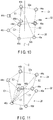
- the first energy emitting portion 24 provided in the distal side coil body 32a of the tissue catching portion 32 have five emitters 44a, 44b, 44c, 44d, and 44e
- the second energy emitting portion 26 provided in the proximal side coil body 32b of the tissue catching portion 32 have five emitters 46a, 46b, 46c, 46d, and 46e. That is, the number of the emitters 44 and the number of the emitters 46 may be odd.
- the emitters 44 and 46 are located at the vertices of an equilateral pentagon around the central axis (center of gravity) C.
- the controller 14 suitably controls the energy source 72 and the switch portion 74 so that the pair of emitters 44 and 46 facing each other along the direction of the central axis C emit the energy E1 to the tissues between the pair of facing emitters 44 and 46, as has been described in the first embodiment. That is, the controller 14 controls the switch portion 74 to apply the energy E1 across the more proximal emitters 44a and 46a, for example, the emitter 44a and the emitter 46a. The controller 14 then controls the switch portion 74 to emit energy to, for example, the tissues L1 and L2 between the emitters 44b and 46b, between the emitters 44c and 46c, and between the emitters 44d and 46d in order to annularly form a joining portion.
- the controller 14 suitably controls the energy source 72 and the switch portion 74 so that the energy E2 is emitted to the tissues between the emitters 44b and 46d and the tissues between the emitters 44b and 46e in order.
- energy may naturally be simultaneously output to the tissues between the emitters 44b and 46d and the tissues between the emitters 44b and 46e. That is, the controller 14 controls the switch portion 74 to apply the energy E2 across the more proximal emitters 44b and 46d and emitters 44b and 46e, for example, the emitters 44b and 46d and the emitters 44b and 46e.
- the emitters 44 and 46 in this embodiment do not face each other across the central axis C.
- the later-described direction in which the energy E2 flows between the emitters 44 and 46 is skew relative to the central axis C.
- segments connecting the emitter 44b to the emitters 46d and 46e are skew relative to the central axis C.
- the controller 14 switches, by the switch portion 74, the emitters 44 and 46 to emit energy, to the emitter 44a and the emitters 46c and 46d, the emitter 44b and the emitters 46d and 46e, the emitter 44c and the emitters 46e and 46a, the emitter 44d and the emitters 46a and 46b, and the emitter 44e and the emitters 46b and 46c in order. That is, the controller 14 suitably controls the switch portion 74 so that energy can be emitted to a part of the treatment target caught between at least one of the first energy emitters 44 and at least one of the second energy emitters 46.
- the tissues on the central axis C are cauterized and removed so that the hole H is formed in the tissues L1 and L2.
- the tissues L1 and L2 around the hole H are mutually joined.
- the treatment device 12 can be endoscopically used, and can therefore maintain a minimally invasive state when treating the treatment target, and can also mutually join tissues to obtain high joining force earlier by a simple procedure. It is also possible to mutually join tissues and form a hole that maintains a communicating state depending on the direction of the input of energy.
- the treatment system 10 in this embodiment it is possible to maintain a minimally invasive state when treating the treatment target, and mutually join tissues to obtain a high joining force earlier by a simple procedure. It is also possible to mutually join tissues and form a hole that maintains a communicating state depending on the direction of the input of energy.
- the third embodiment is described with reference to FIG. 11 .
- This embodiment is a modification of the first and second embodiments, and the same components or components having the same functions as those described in the first and second embodiments are provided with the same reference marks as much as possible and are not described in detail.
- the first energy emitting portion 24 provided in the distal side coil body 32a of the tissue catching portion 32 have five emitters 44a, 44b, 44c, 44d, and 44e
- the second energy emitting portion 26 provided in the proximal side coil body 32b of the tissue catching portion 32 have four emitters 46a, 46b, 46c, and 46d. That is, the numbers of the emitters 44 and 46 do not need to be the same. The number of the emitters 44 and the number of the emitters 46 may be even or odd.
- each of the emitters 44 of the first energy emitting portion 24 is located at the vertex of an equilateral pentagon around the central axis (center of gravity) C
- each of the emitters 46 of the second energy emitting portion 26 is located at the vertex of a square having the center of gravity on the central axis C.
- the controller 14 suitably controls the energy source 72 and the switch portion 74 so that the energy E1 is emitted to the tissues between the emitters 46c and 44c and the tissues between the emitters 46c and 44d in order.
- energy may naturally be simultaneously output to the tissues between the emitters 46c and 44c and the tissues between the emitters 46c and 44d.
- the emitters 44 and 46 in this embodiment do not face each other parallel to the central axis C, but face each other substantially along the central axis C.
- the later-described direction in which the energy E1 flows between the emitters 44 and 46 does not need to be parallel to the central axis C.
- segments connecting the emitter 44e to the emitters 44c, 44d, and 44e are not parallel to the central axis C. That is, the controller 14 controls the switch portion 74 to apply the energy E1 across the more proximal emitters 44 and 46 out of the emitters 44 of the first energy emitting portion 24 and the emitters 46 of the second energy emitting portion 26.
- the controller 14 switches, by the switch portion 74, the emitters 44 and 46 to emit energy, to the emitter 44a and the emitters 44a, 44b, and 44e, the emitter 44b and the emitters 44a, 44b, and 44c, the emitter 44c and the emitters 44c, 44d, and 44e, and the emitter 46d and the emitters 44d and 44e in order by way of example.
- the direction in which the energy E1 flows between the emitters 44 and 46 is not parallel to the central axis C, much energy is input substantially parallel to the central axis C.
- a joining portion is annularly formed.
- the controller 14 suitably controls the energy source 72 and the switch portion 74 so that the energy E2 is emitted to the tissues between the emitters 46c and 44a and the tissues between the emitters 46c and 44b in order.
- energy may naturally be simultaneously output to the tissues between the emitters 46c and 44a and the tissues between the emitters 46c and 44b.
- the emitters 44 and 46 in this embodiment do not face each other across the central axis C. That is, the controller 14 controls the switch portion 74 to apply the energy E2 across the more proximal emitters 46c and 44a and emitters 46c and 44b, for example, the emitters 46c and 44a and the emitters 46c and 44b.
- the controller 14 controls the switch portion 74 to apply the energy E2 across the more proximal emitters 46c and 44a and emitters 46c and 44b, for example, the emitters 46c and 44a and the emitters 46c and 44b.
- the tissues on the central axis C are cauterized and removed so that the hole H is formed in the tissues L1 and L2.
- the tissues L1 and L2 around the hole H are mutually joined.
- the treatment device 12 can be endoscopically used, and can therefore maintain a minimally invasive state when treating the treatment target, and can also mutually join tissues to obtain high joining force earlier by a simple procedure. It is also possible to mutually join tissues and form a hole that maintains a communicating state depending on the direction of the input of energy.
- the treatment system 10 in this embodiment it is possible to maintain a minimally invasive state when treating the treatment target, and mutually join tissues to obtain a high joining force earlier by a simple procedure. It is also possible to mutually join tissues and form a hole that maintains a communicating state depending on the direction of the input of energy.
- the areas of the respective emitters 44 and 46 do not need to be the same.
- the shape-memory alloy is used for the catching portion 32 of the linear member 22 so that the linear member 22 is deformable between the substantially straight state and the tissue catching state in the example described above in the first embodiment
- an elastically deformable component such as a coil spring may be used as the catching portion 32 and brought into the substantially straight state from the tissue catching state and then disposed in the tubular body 82 of the applicator 28.
- the catching portion 32 can catch the tissues L1 and L2 in the same manner as the shape-memory alloy, and energy can be emitted from the energy emitting portions 24 and 26.
- Item 1 A joining method to endoscopically mutually and join living tissues, the method comprising:
- Item 2 The method according to Item 1, wherein the heat energy is emitted to between energy emitters close to each other between the first and second catching bodies.
- Item 3 The method according to Item 2, wherein emission positions of the heat energy are switched in order, and a joining portion is annularly formed at the end of a treatment.
- Item 4 A hole forming method to endoscopically form a hole in living tissues, the method comprising:
- Item 5 The method according to Item 1, wherein the heat energy is emitted to between energy emitters located apart from each other between the first and second catching bodies.
- Item 6 The method according to Item 5, wherein emission positions of the heat energy are switched in order, and a joining portion is annularly formed and a hole H is formed inside the annular portion at the end of a treatment.
- 10 ⁇ Living tissue treatment system 12 ⁇ Living tissue treatment device, 14 ⁇ Controller, 22 ⁇ Linear member, 24 ⁇ First energy emitting portion, 26 ⁇ Second energy emitting portion, 28 ⁇ Applicator, 32 ⁇ Tissue catching portion, 32a ⁇ Distal side coil body, 32b ⁇ Proximal side coil body, 34 ⁇ Pusher portion, 44 ⁇ First energy emitter, 46 ⁇ Second energy emitter, 54,56 ⁇ Electrical leads, 58 ⁇ Connector, 72 ⁇ Energy source, 74 ⁇ O utput state switch portion, 82 ⁇ Tubular body, 84 ⁇ Puncture portion.
Landscapes
- Health & Medical Sciences (AREA)
- Surgery (AREA)
- Life Sciences & Earth Sciences (AREA)
- Engineering & Computer Science (AREA)
- Molecular Biology (AREA)
- Public Health (AREA)
- Heart & Thoracic Surgery (AREA)
- Medical Informatics (AREA)
- Nuclear Medicine, Radiotherapy & Molecular Imaging (AREA)
- Animal Behavior & Ethology (AREA)
- General Health & Medical Sciences (AREA)
- Biomedical Technology (AREA)
- Veterinary Medicine (AREA)
- Cardiology (AREA)
- Physics & Mathematics (AREA)
- Plasma & Fusion (AREA)
- Otolaryngology (AREA)
- Surgical Instruments (AREA)
Abstract
Description
- This invention relates to a treatment device and a treatment system to treat a treatment target of a living tissue by using heat energy.
- In various types of surgery, junction techniques to mutually join living tissues are required. For example, a surgical suturing technique and a mechanical anastomotic technique are known as the junction techniques to mutually joint tissues. Moreover, as disclosed in International Publication No.
2011/083027 , there has been known a treatment instrument to join tissues of a treatment target by using heat energy (high-frequency energy). The treatment instrument disclosed in International Publication No.2011/083027 is capable of obtaining a strong joining force earlier when mutually joining tissues in comparison with the case where living tissues are mutually joined by the surgical suturing technique or the mechanical anastomotic technique. - Endoscopic surgery is widely conducted in order to reduce invasive surgical treatment. However, for example, the treatment instrument disclosed in International Publication No.
2011/083027 has high-frequency electrodes facing each other. It is difficult to insert such high-frequency electrodes through a channel of an endoscope. Accordingly, minimally invasive treatment devices capable of obtaining a strong joining force earlier are needed when living tissues are mutually joined. - This invention is intended to provide a treatment device and a treatment system which maintain a minimally invasive state and which can mutually join tissues by a simple procedure.
- According to one aspect of the present invention, a treatment device includes: a linear member which is deformable between a substantially straight state and a tissue catching state and which is configured to catch a treatment target in a state of being deformed in the tissue catching state; a first energy emitting portion which is provided in the linear member and which is provided at a position to catch the treatment target in a state of the linear member is deformed in the tissue catching state; and a second energy emitting portion which is provided in the linear member in a state of being located apart from the first energy emitting portion, which is provided at a position to catch the treatment target in cooperation with the first energy emitting portion in a state where the linear member is deformed in the tissue catching state, and which is configured to emit energy to the treatment target between the first energy emitting portion and the second energy emitting portion and to treat the treatment target. Brief Description of Drawings
-
FIG. 1 is a schematic diagram showing a treatment system according to first to third embodiments; -
FIG. 2 is a schematic perspective view showing a tissue catching portion (coil portion) of a linear member of a treatment device of the treatment system according to the first embodiment, and showing that energy is emitted between energy emitters which face each other along the central axis of the tissue catching portion; -
FIG. 3 is a schematic longitudinal sectional view showing that the tissue catching portion and a pusher portion of the linear member of the treatment device of the treatment system according to the first to third embodiments are housed in an applicator; -
FIG. 4 is a schematic longitudinal sectional view showing that a puncture portion of the applicator of the treatment device of the treatment system according to the first to third embodiments punctures and pierces a living tissue, and then a distal side coil body of the tissue catching portion of the linear member is protruded relative to the distal end of the applicator and then deformed into a coil state (tissue catching state); -
FIG. 5 is a schematic longitudinal sectional view showing that the distal side coil body of the tissue catching portion of the linear member of the treatment device of the treatment system according to the first to third embodiments is deformed into the coil state, and then the puncture portion of the applicator is pulled out; -
FIG. 6 is a schematic longitudinal sectional view showing that a proximal side coil body of the tissue catching portion of the linear member of the treatment device of the treatment system according to the first to third embodiments is protruded relative to the distal end of the applicator and then deformed into the coil state; -
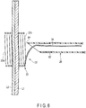
FIG. 7 is a schematic longitudinal sectional view showing that energy is suitably supplied to between the emitters in a state where the tissues are held between a distal side coil and a proximal side coil of the tissue catching portion of the linear member of the treatment device of the treatment system according to the first to third embodiments, to mutually join tissues, and then the linear member is, for example, cut to remove the applicator; -
FIG. 8 is a schematic perspective view showing the tissue catching portion of the linear member of the treatment device of the treatment system according to the first embodiment, and showing that energy is emitted to between the energy emitters facing each other across the central axis of the tissue catching portion; -
FIG. 9 is a schematic longitudinal sectional view showing that energy is suitably supplied to between the emitters in the state where the tissues are held between the distal side coil and the proximal side coil of the tissue catching portion of the linear member of the treatment device of the treatment system according to the first to third embodiments, to mutually join the tissues and form a hole, and then the linear member is, for example, cut to remove the applicator; -
FIG. 10 is a schematic diagram showing the arrangement of first energy emitters and second energy emitters provided in the tissue catching portion of the linear member of the treatment device of the treatment system according to the second embodiment; and -
FIG. 11 is a schematic diagram showing the arrangement of first energy emitters and second energy emitters provided in the tissue catching portion of the linear member of the treatment device of the treatment system according to the third embodiment. - Hereinafter, embodiments of this invention will be described with reference to the drawings.
- The first embodiment is described with reference to
FIG. 1 to FIG. 9 . - It is appropriate that a living
tissue treatment system 10 according to this embodiment shown inFIG. 1 be used together with an unshown endoscope. Thetreatment system 10 includes a livingtissue treatment device 12, and a controller (energy source) 14 which controls so that suitable energy may be supplied to later-described first and secondenergy emitting portions treatment device 12. For example, afoot switch 16 is connected to thecontroller 14. Thefoot switch 16 has first andsecond pedals first pedal 16a is operated. Although described later, a treatment in a hole forming mode (second mode) to form a hole in the first tissue L1 and the second tissue L2 is conducted by way of example when thesecond pedal 16b is operated. It is also appropriate that a hand switch be used together with or instead of thefoot switch 16. It is also appropriate that, for example, push switches equivalent to the first andsecond pedals applicator 28. - The
treatment device 12 according to this embodiment is formed as a disposable type. The later-describedapplicator 28 may be reused after being cleaned, disinfected, and sterilized. - The
treatment device 12 includes alinear member 22, and the first and secondenergy emitting portions treatment device 12 has the applicator (guide tool) 28 to guide thelinear member 22 and the first and secondenergy emitting portions linear member 22, the first and secondenergy emitting portions applicator 28 of thetreatment device 12 can be inserted through a channel of the unshown endoscope in use, and are appropriately inserted through the channel in use, which will be described later. It is appropriate that theapplicator 28 be made of, for example, a resinous material having electric insulating properties. - The
linear member 22 has, for example, a coil-shapedtissue catching portion 32, and apusher portion 34 which can move the catchingportion 32 back and forth relative to the distal end (a later-described puncture portion 84) of theapplicator 28 along a longitudinal direction. It is appropriate that theholding portion 32 and thepusher portion 34 be integrally formed. Thepusher portion 34 may be made of the same material as theholding portion 32, or may be made of a different material. - The catching
portion 32 of thewire member 22 is deformable between a substantially straight state and a tissue catching state such as a coil state having spring characteristics, and can catch the treatment target in a state of being deformed in the tissue catching state. When the catchingportion 32 is prone to be in the tissue catching state, for example, the coil state, the catchingportion 32 has only to exist about several centimeters along a central axis C from its distal end to its proximal end. In a state where thelinear member 22 is deformed in the tissue holding state, it is not only difficult to put thelinear member 22 into a later-describedtubular body 82 of theapplicator 28 but also difficult to put thelinear member 22 into the channel of the endoscope. When thelinear member 22 is put into thetubular body 82 of theapplicator 28 and the channel of the endoscope, thelinear member 22 is substantially straightened and then put in. - It is appropriate that the catching
portion 32 of thelinear member 22 be made of a shape-memory alloy such as a nickel-titanium alloy. For example, when heated, the catchingportion 32 of thelinear member 22 is deformed into the coil-shaped tissue catching state having spring characteristics from the substantially straight state. Thelinear member 22 made of the shape-memory alloy can be formed by adjusting its composition so that thelinear member 22 may maintain the substantially straight state at a temperature (e.g., room temperature) lower than a temperature in a body cavity such as a body temperature and so that thelinear member 22 may be deformed into the tissue catching state at the body temperature. A heater may be disposed in thelinear member 22 or the later-describedpuncture portion 84 of theapplicator 28 in addition to later-describedemitters linear member 22 from the heater to deform thelinear member 22 into the tissue catching state from the substantially straight state. It is also naturally appropriate that thelinear member 22 be elastically deformable between the substantially straight state and the tissue catching state (coil state). - In the explanation below, the
linear member 22 is made of the shape-memory alloy by way of example. - The
tissue catching portion 32 has a distal side coil body (first coil) 32a, and a proximal side coil body *(second coil) 32b provided on the proximal side of the distalside coil body 32a. When thetissue catching portion 32 of thelinear member 22 is deformed into the tissue catching state from the substantially straight state, the distalside coil body 32a is located on the distal side along the central axis C of the tissue catching state (coil state), and the proximalside coil body 32b is located adjacent to the proximal side of the distalside coil body 32a. It is appropriate that the distalside coil body 32 and the proximalside coil body 32b be disposed concentrically with the central axis C when thetissue catching portion 32 is in the tissue catching state. - Each of the first and second
energy emitting portions tissue catching portion 32 of thelinear member 22. Specifically, the firstenergy emitting portion 24 is provided in the distalside coil body 32a, and the secondenergy emitting portion 26 is provided in the proximalside coil body 32b. Thus, the first and secondenergy emitting portions - The first
energy emitting portion 24 faces the secondenergy emitting portion 26 in a state where thetissue catching portion 32 of thelinear member 22 is deformed in the tissue catching state. The firstenergy emitting portion 24 is located at a position to catch the treatment target in cooperation with the secondenergy emitting portion 26. In other words, the secondenergy emitting portion 26 is located at a position to catch the treatment target in cooperation with the firstenergy emitting portion 24 in the state where the catchingportion 32 of thelinear member 22 is deformed in the tissue catching state. Energy is then emitted to the secondenergy emitting portion 26 and the firstenergy emitting portion 24 to treat the treatment target. That is, it is possible to treat the treatment target by emitting energy to the treatment target between the first and secondenergy emitting portions - The first
energy emitting portion 24 has multiple (four, in the example described here)energy emitters linear member 22 when thetissue catching portion 32 is in the substantially straight state. In other words, the respective emitters 44 are located apart at suitable intervals along the winding direction L when the distalside coil body 32a of thetissue catching portion 32 is in the tissue catching state (coil state). The respective energy emitters 44 are electrically insulated from each other. For example, a high-frequency electrode or a heater can be used as each energy emitter 44, so that heat energy can be applied to the treatment target. In the example described here, the high-frequency electrodes are used as the energy emitters 44. - The second
energy emitting portion 26 has multiple (four, in the example described here)energy emitters linear member 22 when thetissue catching portion 32 is in the substantially straight state. In other words, the respective emitters 46 are located apart at suitable intervals along the winding direction L when the proximalside coil body 32b of thetissue catching portion 32 is in the tissue catching state (coil state). The respective energy emitters 46 are electrically insulated from each other. For example, a high-frequency electrode or a heater can be used as each energy emitter 46, so that heat energy can be applied to the treatment target. In the example described here, the high-frequency electrodes are used as the energy emitters 44. - In this embodiment, the catching
portion 32 of the linear member 22_has shape memory. Thus, the energy emitters 44 and 46 which face or substantially face each other in the first and secondenergy emitting portions linear member 22 is in the tissue catching state are determined. As shown inFIG. 2 , when thetissue catching portion 32 is in the tissue catching state, theemitters emitters emitters emitters emitters emitters emitters emitters linear member 22 is deformed in the tissue catching state. Although described later, thecontroller 14 controls a later-describedswitch portion 74 so that energy E1 can be applied across the emitters 44 and 46 that are more proximal among the emitters 44 of the firstenergy emitting portion 24 and the emitters 46 of the secondenergy emitting portion 26 when the tissues L1 and L2 are mutually joined. - It is preferable that the emitters 44 and 46 be disposed to face each other across (and also substantially across) the central axis C of the tissue catching state when the
linear member 22 is deformed in the tissue catching state. As shown inFIG. 8 , theemitters emitters emitters emitters controller 14 controls the later-describedswitch portion 74 so that energy E2 can be applied across the emitters 44 and 46 that are more proximal among the emitters 44 of the firstenergy emitting portion 24 and the emitters 46 of the secondenergy emitting portion 26 when a hole H is formed in the tissues L1 and L2. - It is appropriate that the
linear member 22 be formed into a tubular shape as shown inFIG. 1 . Electrical leads 54a, 54b, 54c, and 54d (the sign 54 is mainly indicated below) electrically connected to the first energy emitters 44, andelectrical leads linear member 22. That is, theelectrical lead 54a is electrically connected to theemitter 44a, theelectrical lead 54b is electrically connected to theemitter 44b, theelectrical lead 54c is electrically connected to theemitter 44c, theelectrical lead 54d is electrically connected to theemitter 44d, theelectrical lead 56a is electrically connected to theemitter 46a, theelectrical lead 56b is electrically connected to theemitter 46b, theelectrical lead 56c is electrically connected to theemitter 46c, and theelectrical lead 56d is electrically connected to theemitter 46d. Each of the electrical leads 54 and 56 is attachable to and detachable from thecontroller 14 having a later-describedenergy source 72 by aconnector 58. - The
controller 14 includes theenergy source 72 which can supply suitable energy to the first and secondenergy emitting portions treatment device 12. Thus, the energy output of theenergy source 72 is controlled by thecontroller 14. That is, for example, the energy output amount and energy output time of theenergy source 72 are suitably controlled by thecontroller 14. Theenergy source 72 is electrically connected to each of the emitters 44 of the firstenergy emitting portion 24 by each of the electrical leads 54, and also electrically connected to each of the emitters 46 of the secondenergy emitting portion 26 by each of the electrical leads 56. Thus, energy can be transmitted to each of the emitters 44 and 46 from theenergy source 72 through each of the electrical leads 54 and 56. - The
energy source 72 in the treatment using high-frequency energy is often limited in electric current capacity. It is thus preferable that theenergy source 72 be capable of supplying energy to at least one of the emitters 44 of the firstenergy emitting portion 24 and at least one of the emitters 46 of the secondenergy emitting portion 26 in accordance with the electric current capacity. Therefore, as shown inFIG. 1 , it is preferable for thecontroller 14 to have theswitch portion 74 which switches the output state in preparation for a possible limit of the electric current capacity. Theswitch portion 74 is controlled by thecontroller 14 to select one or more of theemitters energy emitting portion 24, that is, theelectrical leads emitters energy emitting portion 26, that is, theelectrical leads - Therefore, energy can be transmitted to suitable energy emitters 44 and 46 among the energy emitters 44 and 46 from the
energy source 72 of thecontroller 14 through the respective electrical leads 54 and 56. It is preferable that energy be simultaneously output to the pairs ofemitters energy source 72 is not limited in electric current capacity. - When the
switch portion 74 is controlled by thecontroller 14, suitable energy is firstly supplied to theemitters emitters emitters emitters switch portion 74 is controlled so that energy is substantially continuously supplied to the living tissue. That is, thecontroller 14 can control so that, for example, the supply of energy to the tissues between theemitters emitters - The emitters 44 and 46 can be used as sensors to detect biological information such as impedance between the tissues L1 and L2. Thus, a signal of impedance is input to the
controller 14 from the emitters 44 and 46 through the electrical leads 54 and 56. The time of stopping the energy output to the emitters 44 and 46 from theenergy source 72 can be automatically controlled by setting a suitable impedance threshold to thecontroller 14. It is naturally appropriate to set so that energy is output from theenergy source 72 only for a suitable time, and the output is stopped when a set time has elapsed. It is also appropriate to set so that the output is stopped when the impedance threshold is not reached after a predetermined time has elapsed since the start of the energy output to the emitters 44 and 46 from theenergy source 72. - As shown in
FIG. 1 andFIG. 3 , theapplicator 28 includes the tubular body (sheath) 82 and thepuncture portion 84 provided at the distal end of thetubular body 82. Thetubular body 82 brings thelinear member 22 into the substantially straight state when thelinear member 22 is provided in thetubular body 82, and thetubular body 82 houses a protruding portion of thelinear member 22 in the tissue catching state when thelinear member 22 is protruded from the distal end of thetubular body 82. That is, theapplicator 28 has, at its distal end, thepuncture portion 84 which can puncture the treatment target. Thepuncture portion 84 of theapplicator 28 can puncture the treatment target and can pierce the treatment target. - Next, functions of the
tissue treatment system 10 according to this embodiment are described. In the example described here, energy is emitted to the tissues L1 and L2 from the respective emitters 44 and 46 in order by the use of theswitch portion 74. - Firstly described is the case (first mode) to conduct a treatment to join the first tissue L1 and the second tissue L2. Secondly described is the case (second mode) to conduct a treatment to join the first tissue L1 and the second tissue L2 and form the hole H so that the first tissue L1 side and the second tissue L2 side can communicate with each other.
- As shown in
FIG. 3 , the catchingportion 32 of thelinear member 22 is substantially straightened, and then housed in thetubular body 82 of theapplicator 28. As shown inFIG. 1 , theconnector 58 is connected to thecontroller 14. - For example, the distal surface of the distal end of an insertion section of the endoscope is put in to face the treatment target in the body cavity. In a state where the distal surface of the distal end of the insertion section of the endoscope is facing the treatment target in the body cavity, the
puncture portion 84 of theapplicator 28 of thetreatment device 12 in which thelinear member 22 is in the substantially straight state is placed to face the first tissue L1 of the treatment target through a treatment instrument insertion channel of the endoscope. - As shown in
FIG. 4 , the first tissue L1 and the second tissue L2 of the treatment target are pierced by thepuncture portion 84 of theapplicator 28. The distalside coil body 32a of thetissue catching portion 32 of thelinear member 22 is then protruded relative to the distal end (puncture portion 84) of theapplicator 28 by thepusher portion 34. In this instance, the distalside coil body 32a of thetissue catching portion 32 of thelinear member 22 increases in temperature due to, for example, the temperature of the body, and is then deformed into the tissue catching state from the substantially straight state. - As shown in
FIG. 5 , thepuncture portion 84 is pulled out to face the first tissue L1 from the state where thepuncture portion 84 is piercing the first tissue L1 and the second tissue L2. Thus, the distalside coil body 32a is left on the second tissue L2 side. - As shown in
FIG. 6 , the proximalside coil body 32b of the catchingportion 32 of thelinear member 22 is then protruded relative to the distal end (puncture portion 84) of theapplicator 28 by thepusher portion 34. In this instance, the proximalside coil body 32b of the catchingportion 32 of thelinear member 22 increases in temperature due to, for example, the temperature of the body, and is then deformed into the tissue catching state from the substantially straight state. - Thus, the first tissue L1 and the second tissue L2 are caught between the distal
side coil body 32a and the proximalside coil body 32b. That is, the first tissue L1 and the second tissue L2 are caught by the catchingportion 32 and thus come into close contact with each other. In this instance, as shown inFIG. 2 , the catchingportion 32 has shape memory, so that theemitter 44a of the firstenergy emitting portion 24 and theemitter 46a of the secondenergy emitting portion 26 face each other, theemitter 44b of the firstenergy emitting portion 24 and theemitter 46b of the secondenergy emitting portion 26 face each other, theemitter 44c of the firstenergy emitting portion 24 and theemitter 46c of the secondenergy emitting portion 26 face each other, and theemitter 44d of the firstenergy emitting portion 24 and theemitter 46d of the secondenergy emitting portion 26 face each other. - In this state, the
first pedal 16a of thefoot switch 16 connected to thecontroller 14 is stepped on and operated to conduct, for example, a treatment in the first mode. - As shown in
FIG. 2 , thecontroller 14 controls theenergy source 72 and theswitch portion 74 to output a suitable high-frequency energy (heat energy) across theemitter 44a of the firstenergy emitting portion 24 and theemitter 46a of the secondenergy emitting portion 26. Accordingly, the energy E1 is input to the tissues L1 and L2 between theemitters controller 14 controls theswitch portion 74 to apply the energy E1 across the moreproximal emitters emitter 44a and theemitter 46b. - In this instance, biological information such as impedance regarding the tissues L1 and L2 between the
emitters emitters controller 14 controls theenergy source 72 to stop the output of the high-frequency energy. - The
controller 14 controls theenergy source 72 and theswitch portion 74 to output a suitable high-frequency energy across theemitter 44b of the firstenergy emitting portion 24 and theemitter 46b of the secondenergy emitting portion 26 so that the tissues L1 and L2 between theemitters emitters emitters emitters - Similarly, the
controller 14 applies a suitable output of high-frequency energy across theemitters emitters controller 14 applies a suitable output of high-frequency energy to theemitters emitters emitters emitters emitters emitters - That is, the
controller 14 controls theenergy source 72 and theswitch portion 74 to emit the energy E1 to the respective emitters 44 and 46 adjacent to each other in order. Thus, an annular joining portion is formed in the tissues L1 and L2, so that the tissues L1 and L2 are mutually joined. - The
controller 14 informs the user that a series of works to join the tissues L1 and L2 has been finished, for example, by sound and/or monitor display. The user releases thefirst pedal 16a. - The
linear member 22 is cut after the output of energy to the emitters 44 and 46 from theenergy source 72 has been stopped. In this instance, it is preferable to cut the portion of thelinear member 22 protruding from the distal end of theapplicator 28. For example, it is preferable to cut the part located in the vicinity of the boundary between the catchingportion 32 and thepusher portion 34. This work is performed with, for example, different forceps, which are endoscopically inserted. - The
pusher portion 34 of thelinear member 22 and theapplicator 28 are then pulled out of the channel of the endoscope. Thus, the catchingportion 32 of thelinear member 22 is left catching the tissues L1 and L2 in a state where the tissues L1 and L2 are mutually joined. The catchingportion 32 keeps catching the tissues L1 and L2, and can therefore keep the force of mutually joining the tissues L1 and L2. - In the example described here, the
controller 14 controls theswitch portion 74 to emit energy to theemitters emitters emitters emitters controller 14 controls theswitch portion 74 to output energy to the emitters 44 and 46 along the winding direction L in the described example. It is also appropriate that energy is emitted to, for example, theemitters emitters emitters emitters controller 14 controls theswitch portion 74 to simultaneously supply energy to the emitters 44 and 46 that make a pair (that face along the direction of the central axis C), for example, theemitters - In
FIG. 2 , theemitters emitters emitters emitters energy emitting portion 24 are illustrated as being located apart from each other by a suitable distance. Similarly, theemitters emitters emitters emitters energy emitting portion 26 are illustrated as being located apart from each other by a suitable distance. Thus, for example, when the tissues L1 and L2 are mutually joined, the joining portion can have an annular shape of a broken line rather than an annular shape of a solid line. On the other hand, it is possible to form the annular joining portion of the solid line in the first tissue L1 and the second tissue L2 to mutually join the tissues L1 and L2 by reducing the distance between the emitters 44 and 46 adjacent along the winding direction (the longitudinal direction of the linear member 22) (increasing the areas of the emitters 44 and 46) and suitably controlling the output energy to the emitters 44 and 46. - In the case (second mode) described next, the first tissue L1 and the second tissue L2 are mutually joined and the hole H is formed so that the first tissue L1 side and the second tissue L2 side communicate with each other. The same parts as those with the functions in the first mode are not described.
- As shown in
FIG. 6 , the first tissue L1 and the second tissue L2 are caught between the distalside coil body 32a and the proximalside coil body 32b. That is, the first tissue L1 and the second tissue L2 come into close contact with each other. In this instance, as shown inFIG. 8 , theemitter 44a of the firstenergy emitting portion 24 and theemitter 46a of the secondenergy emitting portion 26 face each other, theemitter 44b of the firstenergy emitting portion 24 and theemitter 46b of the secondenergy emitting portion 26 face each other, theemitter 44c of the firstenergy emitting portion 24 and theemitter 46c of the secondenergy emitting portion 26 face each other, and theemitter 44d of the firstenergy emitting portion 24 and theemitter 46d of the secondenergy emitting portion 26 face each other. - In this state, the
second pedal 16b of thefoot switch 16 connected to thecontroller 14 is stepped on and operated to conduct, for example, a treatment in the second mode. - As shown in
FIG. 8 , thecontroller 14 controls theenergy source 72 and theswitch portion 74 to output a suitable high-frequency energy (heat energy) across theemitter 44a of the firstenergy emitting portion 24 and theemitter 46c of the secondenergy emitting portion 26. Accordingly, the energy E2 is input to the tissues L1 and L2 between theemitters emitters controller 14 controls theswitch portion 74 to apply the energy E2 across the moredistal emitters emitter 44a and theemitter 46c. - In this instance, biological information such as impedance regarding the tissues L1 and L2 between the
emitters emitters controller 14 controls theenergy source 72 to stop the output of the high-frequency energy. The impedance threshold in the first mode and the impedance threshold in the second mode may be the same or different. - The
controller 14 controls theenergy source 72 and theswitch portion 74 to output a suitable high-frequency energy across theemitter 44b of the firstenergy emitting portion 24 and theemitter 46d of the secondenergy emitting portion 26 so that the tissues L1 and L2 between theemitters emitters emitters - Similarly, the
controller 14 applies a suitable output of high-frequency energy to theemitters emitters controller 14 applies a suitable output of high-frequency energy across theemitters emitters portion 32 is high in the tissues L1 and L2. Therefore, the center (the part on the central axis C) is obliquely cauterized through the energy E2 across the central axis C. Thus, as shown inFIG. 9 , the living tissues on the central axis C become necrotic and are removed, and the hole H is formed. The parts around the hole H are annularly and mutually joined by energy density. - That is, the
controller 14 controls theenergy source 72 and theswitch portion 74 to emit the energy E2 to the respective emitters 44 and 46 that are located apart from each other. Thus, in the tissues L1 and L2, the annular hole H is formed on the central axis C, and the parts around the hole H are mutually joined. Therefore, it is possible to form the hole H which keeps the tissues L1 and L2 in communication with each other by using thetreatment system 10. - The
controller 14 informs the user that a series of works to form the hole H in the tissues L1 and L2 has been finished, for example, by sound and/or monitor display. The user releases thesecond pedal 16b. - As in the work in the first mode, the
linear member 22 is cut after the output of energy to the emitters 44 and 46 from theenergy source 72 has been stopped. - The
pusher portion 34 of thelinear member 22 and theapplicator 28 are then pulled out of the channel of the endoscope. Thus, the hole H is formed on the central axis C in the part in which the tissues L1 and L2 are caught by the catchingportion 32, and the catchingportion 32 of thelinear member 22 is left catching the tissues L1 and L2 in a state where the parts around the hole H are joined. The catchingportion 32 keeps catching the tissues L1 and L2, and can therefore keep the force of mutually joining the tissues L1 and L2. - In the example described here, the
controller 14 controls theswitch portion 74 to emit energy to theemitters emitters emitters emitters emitters emitters emitters emitters controller 14 controls theswitch portion 74 to simultaneously supply energy to the emitters 44 and 46 that make a pair (that face each other across the direction of the central axis C), for example, theemitters - As described above, the following can be said according to the
treatment system 10 in this embodiment. - When surgical suture is endoscopically conducted, work needs to be performed in a narrow space, and therefore a high-level technique is required. The
treatment device 12 according to this embodiment can be inserted through the channel of the endoscope in use. Thistreatment device 12 only requires that after the treatment target is punctured by theapplicator 28, the distalside coil body 32a of thetissue catching portion 32 of thelinear member 22 be protruded, and theapplicator 28 be retracted to protrude the proximalside coil body 32b of the catchingportion 32, and then energy be supplied to theemitters side coil body 32a and the proximalside coil body 32b from theenergy source 72 in accordance with a treatment. The work to catch the tissues L1 and L2 can be performed merely by suitably moving theapplicator 28 and thelinear member 22 in the direction of the central axis C. Therefore, when thetreatment device 12 according to this embodiment is used, the work to catch the tissues L1 and L2 can be performed by a simple operation. - It is possible to form the annular joining portion or form the hole H in the treatment target by emitting heat energy from the
energy emitting portions tissue catching portion 32 of thelinear member 22. Specifically, it is possible to control theenergy source 72 and theswitch portion 74 by thecontroller 14 to apply the energy E1 across the moreproximal emitters emitter energy source 72 and theswitch portion 74 by thecontroller 14 to apply the energy E2 across the moredistal emitters emitter - Thus, this
treatment system 10 conducts a treatment to degenerate the living tissues L1 and L2 by using heat energy, and can therefore considerably reduce the work time when mutually joining the tissues L1 and L2 of the treatment target and when mutually joining the tissues L1 and L2 and also forming the hole H. When mutually joining the tissues and forming the hole H therein, it is not necessary to simply stop blood flow to wait for cells to become necrotic, and it is possible to form the hole H in a short time and mutually join the parts around the hole H by actively inputting heat energy to the living tissue. This hole H can keep the tissue L1 side and the tissue L2 side in communication with each other. - The
treatment device 12 according to this embodiment can be endoscopically used, and can therefore maintain a minimally invasive state when treating the treatment target. It is also possible to mutually join tissues to obtain high joining force earlier by a simple procedure. It is also possible to mutually join tissues and form a hole that maintains a communicating state depending on the direction of the input of energy. Similarly, according to thetreatment system 10 in this embodiment, it is possible to maintain a minimally invasive state when treating the treatment target, and mutually join tissues to obtain high joining force earlier by a simple procedure. It is also possible to mutually join tissues and form a hole that maintains a communicating state depending on the direction of the input of energy. - In
FIG. 2 , theemitters emitters emitters emitters energy emitting portion 24 are illustrated as being located apart from each other by a suitable distance. Similarly, theemitters emitters emitters emitters energy emitting portion 26 are illustrated as being located apart from each other by a suitable distance. It is possible to annularly join the first tissue L1 and the second tissue L2 by reducing the distance between the emitters 44 and 46 adjacent in the winding direction (the longitudinal direction of the linear member 22) L and suitably controlling the output energy to the emitters 44 and 46. - In the example described here, the pairs of
emitters emitters - In the example described here, the pairs of
emitters emitters - Although it has been described that the first mode is one treatment work and the second mode is another treatment work, the joining work in the first mode and the hole making work in the second mode may naturally be a series of treatment works, for example.
- The second embodiment is described with reference to
FIG. 10 . This embodiment is a modification of the first embodiment, and the same components or components having the same functions as those described in the first embodiment are provided with the same reference marks as much as possible and are not described in detail. - In the example described in the first embodiment, the first
energy emitting portion 24 has four emitters 44, and the secondenergy emitting portion 26 has four emitters 46. - As schematically shown in
FIG. 10 , it is also appropriate that the firstenergy emitting portion 24 provided in the distalside coil body 32a of thetissue catching portion 32 have fiveemitters energy emitting portion 26 provided in the proximalside coil body 32b of thetissue catching portion 32 have fiveemitters - In this case, in the first mode, the
controller 14 suitably controls theenergy source 72 and theswitch portion 74 so that the pair of emitters 44 and 46 facing each other along the direction of the central axis C emit the energy E1 to the tissues between the pair of facing emitters 44 and 46, as has been described in the first embodiment. That is, thecontroller 14 controls theswitch portion 74 to apply the energy E1 across the moreproximal emitters emitter 44a and theemitter 46a. Thecontroller 14 then controls theswitch portion 74 to emit energy to, for example, the tissues L1 and L2 between theemitters emitters emitters - In contrast, in the second mode, for example, the
emitter 44b and each of theemitters controller 14 suitably controls theenergy source 72 and theswitch portion 74 so that the energy E2 is emitted to the tissues between theemitters emitters emitters emitters controller 14 controls theswitch portion 74 to apply the energy E2 across the moreproximal emitters emitters emitters emitters - Here, the emitters 44 and 46 in this embodiment do not face each other across the central axis C. Thus, the later-described direction in which the energy E2 flows between the emitters 44 and 46 is skew relative to the central axis C. For example, segments connecting the
emitter 44b to theemitters - When a treatment in the second mode is conducted, the
controller 14 switches, by theswitch portion 74, the emitters 44 and 46 to emit energy, to theemitter 44a and theemitters emitter 44b and theemitters emitter 44c and theemitters emitter 44d and theemitters emitter 44e and theemitters controller 14 suitably controls theswitch portion 74 so that energy can be emitted to a part of the treatment target caught between at least one of the first energy emitters 44 and at least one of the second energy emitters 46. Thus, although the direction in which the energy E2 flows between the emitters 44 and 46 is skew relative to the central axis C, much energy is input to the vicinity of the central axis C, and the energy density in the vicinity of the central axis C is higher. Thus, as in the treatment in the second mode described in the first embodiment, the tissues on the central axis C are cauterized and removed so that the hole H is formed in the tissues L1 and L2. The tissues L1 and L2 around the hole H are mutually joined. - Consequently, as in the first embodiment, the
treatment device 12 according to this embodiment can be endoscopically used, and can therefore maintain a minimally invasive state when treating the treatment target, and can also mutually join tissues to obtain high joining force earlier by a simple procedure. It is also possible to mutually join tissues and form a hole that maintains a communicating state depending on the direction of the input of energy. Similarly, according to thetreatment system 10 in this embodiment, it is possible to maintain a minimally invasive state when treating the treatment target, and mutually join tissues to obtain a high joining force earlier by a simple procedure. It is also possible to mutually join tissues and form a hole that maintains a communicating state depending on the direction of the input of energy. - The third embodiment is described with reference to
FIG. 11 . This embodiment is a modification of the first and second embodiments, and the same components or components having the same functions as those described in the first and second embodiments are provided with the same reference marks as much as possible and are not described in detail. - As schematically shown in
FIG. 11 , it is also appropriate that the firstenergy emitting portion 24 provided in the distalside coil body 32a of thetissue catching portion 32 have fiveemitters energy emitting portion 26 provided in the proximalside coil body 32b of thetissue catching portion 32 have fouremitters - In this embodiment, for simplification of explanation, each of the emitters 44 of the first
energy emitting portion 24 is located at the vertex of an equilateral pentagon around the central axis (center of gravity) C, and each of the emitters 46 of the secondenergy emitting portion 26 is located at the vertex of a square having the center of gravity on the central axis C. - In this case, in the first mode, for example, one
emitter 46c of the secondenergy emitting portion 26 and twoemitters energy emitting portion 24 make pairs. Thus, thecontroller 14 suitably controls theenergy source 72 and theswitch portion 74 so that the energy E1 is emitted to the tissues between theemitters emitters emitters emitters - Here, the emitters 44 and 46 in this embodiment do not face each other parallel to the central axis C, but face each other substantially along the central axis C. Thus, the later-described direction in which the energy E1 flows between the emitters 44 and 46 does not need to be parallel to the central axis C. For example, segments connecting the
emitter 44e to theemitters controller 14 controls theswitch portion 74 to apply the energy E1 across the more proximal emitters 44 and 46 out of the emitters 44 of the firstenergy emitting portion 24 and the emitters 46 of the secondenergy emitting portion 26. - When a treatment in the first mode is conducted, the
controller 14 switches, by theswitch portion 74, the emitters 44 and 46 to emit energy, to theemitter 44a and theemitters emitter 44b and theemitters emitter 44c and theemitters emitter 46d and theemitters - In contrast, in the second mode, for example, the
emitter 46c and each of theemitters controller 14 suitably controls theenergy source 72 and theswitch portion 74 so that the energy E2 is emitted to the tissues between theemitters emitters emitters emitters - Here, the emitters 44 and 46 in this embodiment do not face each other across the central axis C. That is, the
controller 14 controls theswitch portion 74 to apply the energy E2 across the moreproximal emitters emitters emitters emitters - Consequently, as in the first and second embodiments, the
treatment device 12 according to this embodiment can be endoscopically used, and can therefore maintain a minimally invasive state when treating the treatment target, and can also mutually join tissues to obtain high joining force earlier by a simple procedure. It is also possible to mutually join tissues and form a hole that maintains a communicating state depending on the direction of the input of energy. Similarly, according to thetreatment system 10 in this embodiment, it is possible to maintain a minimally invasive state when treating the treatment target, and mutually join tissues to obtain a high joining force earlier by a simple procedure. It is also possible to mutually join tissues and form a hole that maintains a communicating state depending on the direction of the input of energy. - Although not shown, the areas of the respective emitters 44 and 46 do not need to be the same.
- Although the shape-memory alloy is used for the catching
portion 32 of thelinear member 22 so that thelinear member 22 is deformable between the substantially straight state and the tissue catching state in the example described above in the first embodiment, an elastically deformable component such as a coil spring may be used as the catchingportion 32 and brought into the substantially straight state from the tissue catching state and then disposed in thetubular body 82 of theapplicator 28. Even when the catchingportion 32 is formed as above, the catchingportion 32 can catch the tissues L1 and L2 in the same manner as the shape-memory alloy, and energy can be emitted from theenergy emitting portions - The following can be said according to the embodiments described above.
-
Item 1. A joining method to endoscopically mutually and join living tissues, the method comprising: - using an
applicator 28 to pierce treatment target living tissues L1 and L2 from one side (tissue L1 side) to the other side (tissue L2 side); - ejecting a first catching
body 32a of alinear member 22 to the other side from the applicator; pulling back the applicator to the one side; - ejecting a
second catching body 32b of thelinear member 22 to the one side from the applicator, and catching the living tissues L1 and L2 in cooperation with the first catching body; - emitting heat energy to the living tissues between the first and second catching bodies to mutually join the living tissues by the heat energy in a state of catching the living tissues with the first and second catching bodies;
- cutting the proximal sides of the first and second catching
bodies - pulling out the applicator, and pulling out the proximal side of the linear member from the cut position.
- Item 2. The method according to
Item 1, wherein the heat energy is emitted to between energy emitters close to each other between the first and second catching bodies. - Item 3. The method according to Item 2, wherein emission positions of the heat energy are switched in order, and a joining portion is annularly formed at the end of a treatment.
- Item 4. A hole forming method to endoscopically form a hole in living tissues, the method comprising:
- using an
applicator 28 to pierce treatment target living tissues L1 and L2 from one side (tissue L1 side) to the other side (tissue L2 side); - ejecting a first catching
body 32a of alinear member 22 to the other side from the applicator; pulling back the applicator to the one side; - ejecting a
second catching body 32b of thelinear member 22 to the one side from the applicator, and catching the living tissues L1 and L2 in cooperation with the first catching body; - emitting heat energy to the living tissues between the first and second catching bodies to mutually join the living tissues by the heat energy in a state of catching the living tissues with the first and second catching bodies, and form a hole;
- cutting the proximal sides of the first and second catching
bodies - pulling out the applicator, and pulling out the proximal side of the linear member from the cut position.
- Item 5. The method according to
Item 1, wherein the heat energy is emitted to between energy emitters located apart from each other between the first and second catching bodies. - Item 6. The method according to Item 5, wherein emission positions of the heat energy are switched in order, and a joining portion is annularly formed and a hole H is formed inside the annular portion at the end of a treatment.
- Although the several embodiments have been specifically described above with reference to the drawings, the present invention is not restricted to the foregoing embodiments, and it includes all embodiments carried out without departing from the gist thereof.
- 10···Living tissue treatment system, 12···Living tissue treatment device, 14···Controller, 22···Linear member, 24··· First energy emitting portion, 26···Second energy emitting portion, 28···Applicator, 32···Tissue catching portion, 32a··· Distal side coil body, 32b···Proximal side coil body, 34··· Pusher portion, 44···First energy emitter, 46···Second energy emitter, 54,56···Electrical leads, 58···Connector, 72···Energy source, 74···Output state switch portion, 82···Tubular body, 84···Puncture portion.
Claims (14)
- A treatment device comprising:a linear member which is deformable between a substantially straight state and a tissue catching state and which is configured to catch a treatment target in a state of being deformed in the tissue catching state;a first energy emitting portion which is provided in the linear member and which is provided at a position to catch the treatment target in a state of the linear member is deformed in the tissue catching state; anda second energy emitting portion which is provided in the linear member in a state of being located apart from the first energy emitting portion, which is provided at a position to catch the treatment target in cooperation with the first energy emitting portion in a state where the linear member is deformed in the tissue catching state, and which is configured to emit energy to the treatment target between the first energy emitting portion and the second energy emitting portion and to treat the treatment target.
- The treatment device according to claim 1, wherein the first and second energy emitting portions are disposed to face each other at positions along a central axis of the tissue catching state or positions substantially along the central axis, in a state where the linear member is deformed in the tissue catching state.
- The treatment device according to claim 1, wherein the first and second energy emitting portions are disposed to face each other at positions which is across a central axis of the tissue catching state or which is skew relative to the central axis in the state where the linear member is deformed in the tissue catching state.
- The treatment device according to claim 1, wherein:the first energy emitting portion includes first energy emitters located apart from each other,the second energy emitting portion includes second energy emitters located apart from each other, andenergy is emittable to a part of the treatment target caught between at least one of the first energy emitters and at least one of the second energy emitters.
- The treatment device according to claim 4, wherein energy is emittable to a part caught between one of the first energy emitters and the most proximal energy emitter among the second energy emitters relative to the one of the first energy emitters.
- The treatment device according to claim 4, wherein energy is emittable to a part caught between one of the first energy emitters and the most distal energy emitter among the second energy emitters relative to the one of the first energy emitters.
- The treatment device according to claim 4, wherein:the first energy emitters are electrically insulated from each other, andthe second energy emitters are electrically insulated from each other.
- The treatment device according to claim 1, further comprising a guide tool which brings the linear member into the substantially straight state when the guide tool is provided inside the linear member and which brings a protruding part of the linear member into the tissue catching state when the linear member is protruded from the distal end of the guide tool.
- The treatment device according to claim 8, wherein the guide tool includes, at its distal end, a puncture portion configured to puncture the treatment target.
- The treatment device according to claim 1, wherein the first and second energy emitting portions include high-frequency electrodes.
- The treatment device according to claim 1, wherein the first and second energy emitting portions include heaters.
- A treatment system comprising:the treatment device according to claim 1; anda controller which includes an energy source configured to supply suitable energy to the first and second energy emitting portions of the treatment device and which controls the energy source.
- The treatment system according to claim 12, wherein:the first energy emitting portion of the treatment device includes first energy emitters located apart from each other,the second energy emitting portion of the treatment device includes second energy emitters located apart from each other, andthe controller is configured to emit energy to at least one selected from the first energy emitters and at least one selected from the second energy emitters.
- The treatment system according to claim 12, wherein:the first energy emitting portion of the treatment device includes first energy emitters located apart from each other,the second energy emitting portion of the treatment device includes second energy emitters located apart from each other, andthe controller includes a switch portion which is switchable to a state where energy flow between the first energy emitters and the second energy emitters along the central axis of the tissue catching state or substantially along the central axis of the tissue catching state when the linear member is in the tissue catching state, and a state where energy flow between the first energy emitters and the second energy emitters which is across the central axis of the tissue catching state or which is skew relative to the central axis of the tissue catching state.
Applications Claiming Priority (2)
| Application Number | Priority Date | Filing Date | Title |
|---|---|---|---|
| JP2014048912 | 2014-03-12 | ||
| PCT/JP2015/053269 WO2015137024A1 (en) | 2014-03-12 | 2015-02-05 | Treatment device and treatment system |
Publications (2)
| Publication Number | Publication Date |
|---|---|
| EP3117779A1 true EP3117779A1 (en) | 2017-01-18 |
| EP3117779A4 EP3117779A4 (en) | 2017-11-15 |
Family
ID=54071476
Family Applications (1)
| Application Number | Title | Priority Date | Filing Date |
|---|---|---|---|
| EP15761503.0A Withdrawn EP3117779A4 (en) | 2014-03-12 | 2015-02-05 | Treatment device and treatment system |
Country Status (5)
| Country | Link |
|---|---|
| US (1) | US20160374757A1 (en) |
| EP (1) | EP3117779A4 (en) |
| JP (1) | JP5945635B2 (en) |
| CN (1) | CN106028972A (en) |
| WO (1) | WO2015137024A1 (en) |
Cited By (1)
| Publication number | Priority date | Publication date | Assignee | Title |
|---|---|---|---|---|
| GB2569697A (en) * | 2017-11-14 | 2019-06-26 | Spiration Inc D/B/A Olympus Respiratory America | Fistula creation for fluid drainage |
Families Citing this family (1)
| Publication number | Priority date | Publication date | Assignee | Title |
|---|---|---|---|---|
| CN107928783B (en) * | 2017-12-29 | 2024-09-06 | 山前(珠海)医疗科技有限公司 | Cryoablation catheter, cryoablation operating device and cryoablation equipment |
Family Cites Families (28)
| Publication number | Priority date | Publication date | Assignee | Title |
|---|---|---|---|---|
| US4010758A (en) * | 1975-09-03 | 1977-03-08 | Medtronic, Inc. | Bipolar body tissue electrode |
| US5047027A (en) * | 1990-04-20 | 1991-09-10 | Everest Medical Corporation | Tumor resector |
| US5263493A (en) * | 1992-02-24 | 1993-11-23 | Boaz Avitall | Deflectable loop electrode array mapping and ablation catheter for cardiac chambers |
| US5443463A (en) * | 1992-05-01 | 1995-08-22 | Vesta Medical, Inc. | Coagulating forceps |
| US5431649A (en) * | 1993-08-27 | 1995-07-11 | Medtronic, Inc. | Method and apparatus for R-F ablation |
| US6129724A (en) * | 1993-10-14 | 2000-10-10 | Ep Technologies, Inc. | Systems and methods for forming elongated lesion patterns in body tissue using straight or curvilinear electrode elements |
| US5507743A (en) * | 1993-11-08 | 1996-04-16 | Zomed International | Coiled RF electrode treatment apparatus |
| US5680860A (en) * | 1994-07-07 | 1997-10-28 | Cardiac Pathways Corporation | Mapping and/or ablation catheter with coilable distal extremity and method for using same |
| US5722401A (en) * | 1994-10-19 | 1998-03-03 | Cardiac Pathways Corporation | Endocardial mapping and/or ablation catheter probe |
| US6132438A (en) * | 1995-06-07 | 2000-10-17 | Ep Technologies, Inc. | Devices for installing stasis reducing means in body tissue |
| US6280441B1 (en) * | 1997-12-15 | 2001-08-28 | Sherwood Services Ag | Apparatus and method for RF lesioning |
| FR2791547B1 (en) * | 1999-03-31 | 2001-06-08 | Soprane Sa | BIPOLAR FORCEPS FOR PELVISCOPY |
| IT1315053B1 (en) * | 2000-11-10 | 2003-01-27 | Thermo Med 2000 Kft | NEEDLE-ELECTRODE WITH RADIOFREQUENCY ACTIVE FILAMENT |
| US6497704B2 (en) * | 2001-04-04 | 2002-12-24 | Moshe Ein-Gal | Electrosurgical apparatus |
| US6939348B2 (en) * | 2003-03-27 | 2005-09-06 | Cierra, Inc. | Energy based devices and methods for treatment of patent foramen ovale |
| US8317785B2 (en) * | 2003-05-16 | 2012-11-27 | Trod Medical | Medical device using a coiled electrode |
| WO2005048862A2 (en) * | 2003-11-18 | 2005-06-02 | Scimed Life Systems, Inc. | System and method for tissue ablation |
| WO2005074517A2 (en) * | 2004-01-30 | 2005-08-18 | Nmt Medical, Inc. | Welding systems for closure of cardiac openings |
| WO2006092000A1 (en) * | 2005-03-02 | 2006-09-08 | Cathrx Ltd | A heat treatment catheter |
| US7797056B2 (en) * | 2005-09-06 | 2010-09-14 | Nmt Medical, Inc. | Removable intracardiac RF device |
| EP2001383A4 (en) * | 2006-03-17 | 2011-01-19 | Microcube Llc | Devices and methods for creating continuous lesions |
| US7935114B2 (en) * | 2007-02-14 | 2011-05-03 | Olympus Medical Systems Corp. | Curative treatment system, curative treatment device, and treatment method for living tissue using energy |
| JP2009050592A (en) * | 2007-08-28 | 2009-03-12 | Terumo Corp | Pfo closing device |
| DE102009059192A1 (en) * | 2009-12-17 | 2011-06-22 | Aesculap AG, 78532 | Surgical instrument surgical system and method and method for connecting body tissue parts |
| US9220433B2 (en) * | 2011-06-30 | 2015-12-29 | Biosense Webster (Israel), Ltd. | Catheter with variable arcuate distal section |
| JPWO2013069436A1 (en) * | 2011-11-07 | 2015-04-02 | オリンパスメディカルシステムズ株式会社 | Implant placement device |
| US8888773B2 (en) * | 2012-05-11 | 2014-11-18 | Medtronic Ardian Luxembourg S.A.R.L. | Multi-electrode catheter assemblies for renal neuromodulation and associated systems and methods |
| US20140031804A1 (en) * | 2012-07-26 | 2014-01-30 | Medtronic Cryocath Lp | Device and method for ablating tissue |
-
2015
- 2015-02-05 JP JP2015537051A patent/JP5945635B2/en not_active Expired - Fee Related
- 2015-02-05 EP EP15761503.0A patent/EP3117779A4/en not_active Withdrawn
- 2015-02-05 WO PCT/JP2015/053269 patent/WO2015137024A1/en not_active Ceased
- 2015-02-05 CN CN201580009564.4A patent/CN106028972A/en active Pending
-
2016
- 2016-09-08 US US15/260,066 patent/US20160374757A1/en not_active Abandoned
Cited By (1)
| Publication number | Priority date | Publication date | Assignee | Title |
|---|---|---|---|---|
| GB2569697A (en) * | 2017-11-14 | 2019-06-26 | Spiration Inc D/B/A Olympus Respiratory America | Fistula creation for fluid drainage |
Also Published As
| Publication number | Publication date |
|---|---|
| CN106028972A (en) | 2016-10-12 |
| JPWO2015137024A1 (en) | 2017-04-06 |
| WO2015137024A1 (en) | 2015-09-17 |
| EP3117779A4 (en) | 2017-11-15 |
| JP5945635B2 (en) | 2016-07-05 |
| US20160374757A1 (en) | 2016-12-29 |
Similar Documents
| Publication | Publication Date | Title |
|---|---|---|
| JP6195920B2 (en) | Ablation device having an expandable chamber for anchoring the ablation device to tissue | |
| US7182763B2 (en) | Wound closure device | |
| CN105530992B (en) | Treat the equipment and relevant apparatus in vaginal canal or other natural or operation acquisition hole | |
| US20210251801A1 (en) | Handpiece for treatment, treatment device including handpiece, and treatment method using treatment device | |
| JP5037727B2 (en) | Electrosurgical instrument | |
| JPH10211209A (en) | Medical treatment device | |
| KR101415902B1 (en) | Catheter provided with cauterization system | |
| US11241277B2 (en) | Skin treatment apparatus using RF energy and method for skin treatment using same | |
| CN107205771A (en) | The method and apparatus for being vaporized for thermosurgery and cutting tissue | |
| EP3117779A1 (en) | Treatment device and treatment system | |
| JP2016529988A (en) | Guide catheter with stabilization mechanism and method for inserting guide catheter | |
| US20170281256A1 (en) | Methods and devices for thermal surgical vaporization and incision of tissue | |
| US20210330377A1 (en) | Apparatus and methods for minimally invasive dissection and modification of tissues | |
| JP2016150229A (en) | Catheter for endoscope | |
| AU2022246478B2 (en) | Apparatus and methods for minimally invasive dissection and modification of tissues | |
| KR20120138396A (en) | Double-edged eyelid operation apparatus | |
| CN113597287B (en) | Devices and methods for minimally invasive tissue dissection and modification | |
| CN111465355B (en) | Tissue minimally invasive dissection devices and systems | |
| JP6944996B2 (en) | High frequency treatment tool for endoscopes | |
| CA3011253C (en) | Devices and methods for forming a fistula | |
| JP2007089690A (en) | Conductive traction device for endoscope | |
| JP2019093131A (en) | Fistula creation for fluid drainage | |
| WO2018025360A1 (en) | Catheter for endoscope |
Legal Events
| Date | Code | Title | Description |
|---|---|---|---|
| STAA | Information on the status of an ep patent application or granted ep patent |
Free format text: STATUS: THE INTERNATIONAL PUBLICATION HAS BEEN MADE |
|
| PUAI | Public reference made under article 153(3) epc to a published international application that has entered the european phase |
Free format text: ORIGINAL CODE: 0009012 |
|
| STAA | Information on the status of an ep patent application or granted ep patent |
Free format text: STATUS: REQUEST FOR EXAMINATION WAS MADE |
|
| 17P | Request for examination filed |
Effective date: 20161006 |
|
| AK | Designated contracting states |
Kind code of ref document: A1 Designated state(s): AL AT BE BG CH CY CZ DE DK EE ES FI FR GB GR HR HU IE IS IT LI LT LU LV MC MK MT NL NO PL PT RO RS SE SI SK SM TR |
|
| AX | Request for extension of the european patent |
Extension state: BA ME |
|
| DAX | Request for extension of the european patent (deleted) | ||
| A4 | Supplementary search report drawn up and despatched |
Effective date: 20171013 |
|
| RIC1 | Information provided on ipc code assigned before grant |
Ipc: A61B 18/12 20060101ALI20171009BHEP Ipc: A61B 17/11 20060101AFI20171009BHEP |
|
| STAA | Information on the status of an ep patent application or granted ep patent |
Free format text: STATUS: THE APPLICATION HAS BEEN WITHDRAWN |
|
| 18W | Application withdrawn |
Effective date: 20180206 |