EP3117769A1 - Support tool and biological information acquisition system - Google Patents
Support tool and biological information acquisition system Download PDFInfo
- Publication number
- EP3117769A1 EP3117769A1 EP15761528.7A EP15761528A EP3117769A1 EP 3117769 A1 EP3117769 A1 EP 3117769A1 EP 15761528 A EP15761528 A EP 15761528A EP 3117769 A1 EP3117769 A1 EP 3117769A1
- Authority
- EP
- European Patent Office
- Prior art keywords
- subject
- finger
- support
- light
- bag
- Prior art date
- Legal status (The legal status is an assumption and is not a legal conclusion. Google has not performed a legal analysis and makes no representation as to the accuracy of the status listed.)
- Withdrawn
Links
- 238000009423 ventilation Methods 0.000 claims abstract description 46
- 230000002093 peripheral effect Effects 0.000 claims abstract description 29
- 239000000463 material Substances 0.000 claims abstract description 11
- 230000006835 compression Effects 0.000 claims description 114
- 238000007906 compression Methods 0.000 claims description 114
- 239000008280 blood Substances 0.000 claims description 113
- 210000004369 blood Anatomy 0.000 claims description 113
- 239000000126 substance Substances 0.000 claims description 42
- 230000015572 biosynthetic process Effects 0.000 claims description 31
- 239000012530 fluid Substances 0.000 claims description 21
- 108010054147 Hemoglobins Proteins 0.000 claims description 9
- 102000001554 Hemoglobins Human genes 0.000 claims description 9
- 238000012544 monitoring process Methods 0.000 claims description 9
- 230000035553 feeding performance Effects 0.000 claims description 8
- 238000003825 pressing Methods 0.000 claims description 8
- 238000001514 detection method Methods 0.000 claims description 7
- 230000002123 temporal effect Effects 0.000 claims description 7
- 238000010521 absorption reaction Methods 0.000 claims description 6
- 230000014759 maintenance of location Effects 0.000 claims description 4
- XLYOFNOQVPJJNP-UHFFFAOYSA-N water Substances O XLYOFNOQVPJJNP-UHFFFAOYSA-N 0.000 claims description 4
- 230000014509 gene expression Effects 0.000 description 28
- 238000005259 measurement Methods 0.000 description 25
- 230000006870 function Effects 0.000 description 16
- 230000008033 biological extinction Effects 0.000 description 9
- 210000000282 nail Anatomy 0.000 description 9
- 230000000694 effects Effects 0.000 description 7
- 230000003287 optical effect Effects 0.000 description 7
- 206010030113 Oedema Diseases 0.000 description 6
- QVGXLLKOCUKJST-UHFFFAOYSA-N atomic oxygen Chemical compound [O] QVGXLLKOCUKJST-UHFFFAOYSA-N 0.000 description 6
- 229910052760 oxygen Inorganic materials 0.000 description 6
- 239000001301 oxygen Substances 0.000 description 6
- INGWEZCOABYORO-UHFFFAOYSA-N 2-(furan-2-yl)-7-methyl-1h-1,8-naphthyridin-4-one Chemical compound N=1C2=NC(C)=CC=C2C(O)=CC=1C1=CC=CO1 INGWEZCOABYORO-UHFFFAOYSA-N 0.000 description 3
- 108010064719 Oxyhemoglobins Proteins 0.000 description 3
- 108010002255 deoxyhemoglobin Proteins 0.000 description 3
- 238000012545 processing Methods 0.000 description 3
- 239000007779 soft material Substances 0.000 description 3
- 108010003320 Carboxyhemoglobin Proteins 0.000 description 2
- 230000002542 deteriorative effect Effects 0.000 description 2
- 238000010586 diagram Methods 0.000 description 2
- 238000004519 manufacturing process Methods 0.000 description 2
- 238000012986 modification Methods 0.000 description 2
- 230000004048 modification Effects 0.000 description 2
- 239000011347 resin Substances 0.000 description 2
- 229920005989 resin Polymers 0.000 description 2
- 238000002560 therapeutic procedure Methods 0.000 description 2
- 238000011144 upstream manufacturing Methods 0.000 description 2
- 230000004872 arterial blood pressure Effects 0.000 description 1
- 230000036760 body temperature Effects 0.000 description 1
- 208000016252 change in skin color Diseases 0.000 description 1
- 230000007423 decrease Effects 0.000 description 1
- 230000001419 dependent effect Effects 0.000 description 1
- 238000003745 diagnosis Methods 0.000 description 1
- 238000006073 displacement reaction Methods 0.000 description 1
- 238000011156 evaluation Methods 0.000 description 1
- 210000004905 finger nail Anatomy 0.000 description 1
- 230000031700 light absorption Effects 0.000 description 1
- 238000000034 method Methods 0.000 description 1
- 230000035939 shock Effects 0.000 description 1
Images


Classifications
-
- A—HUMAN NECESSITIES
- A61—MEDICAL OR VETERINARY SCIENCE; HYGIENE
- A61B—DIAGNOSIS; SURGERY; IDENTIFICATION
- A61B5/00—Measuring for diagnostic purposes; Identification of persons
- A61B5/68—Arrangements of detecting, measuring or recording means, e.g. sensors, in relation to patient
- A61B5/6801—Arrangements of detecting, measuring or recording means, e.g. sensors, in relation to patient specially adapted to be attached to or worn on the body surface
- A61B5/6813—Specially adapted to be attached to a specific body part
- A61B5/6825—Hand
- A61B5/6826—Finger
-
- A—HUMAN NECESSITIES
- A61—MEDICAL OR VETERINARY SCIENCE; HYGIENE
- A61B—DIAGNOSIS; SURGERY; IDENTIFICATION
- A61B5/00—Measuring for diagnostic purposes; Identification of persons
- A61B5/0059—Measuring for diagnostic purposes; Identification of persons using light, e.g. diagnosis by transillumination, diascopy, fluorescence
-
- A—HUMAN NECESSITIES
- A61—MEDICAL OR VETERINARY SCIENCE; HYGIENE
- A61B—DIAGNOSIS; SURGERY; IDENTIFICATION
- A61B5/00—Measuring for diagnostic purposes; Identification of persons
- A61B5/02—Detecting, measuring or recording pulse, heart rate, blood pressure or blood flow; Combined pulse/heart-rate/blood pressure determination; Evaluating a cardiovascular condition not otherwise provided for, e.g. using combinations of techniques provided for in this group with electrocardiography or electroauscultation; Heart catheters for measuring blood pressure
- A61B5/02028—Determining haemodynamic parameters not otherwise provided for, e.g. cardiac contractility or left ventricular ejection fraction
-
- A—HUMAN NECESSITIES
- A61—MEDICAL OR VETERINARY SCIENCE; HYGIENE
- A61B—DIAGNOSIS; SURGERY; IDENTIFICATION
- A61B5/00—Measuring for diagnostic purposes; Identification of persons
- A61B5/02—Detecting, measuring or recording pulse, heart rate, blood pressure or blood flow; Combined pulse/heart-rate/blood pressure determination; Evaluating a cardiovascular condition not otherwise provided for, e.g. using combinations of techniques provided for in this group with electrocardiography or electroauscultation; Heart catheters for measuring blood pressure
- A61B5/0205—Simultaneously evaluating both cardiovascular conditions and different types of body conditions, e.g. heart and respiratory condition
-
- A—HUMAN NECESSITIES
- A61—MEDICAL OR VETERINARY SCIENCE; HYGIENE
- A61B—DIAGNOSIS; SURGERY; IDENTIFICATION
- A61B5/00—Measuring for diagnostic purposes; Identification of persons
- A61B5/02—Detecting, measuring or recording pulse, heart rate, blood pressure or blood flow; Combined pulse/heart-rate/blood pressure determination; Evaluating a cardiovascular condition not otherwise provided for, e.g. using combinations of techniques provided for in this group with electrocardiography or electroauscultation; Heart catheters for measuring blood pressure
- A61B5/021—Measuring pressure in heart or blood vessels
- A61B5/02141—Details of apparatus construction, e.g. pump units or housings therefor, cuff pressurising systems, arrangements of fluid conduits or circuits
-
- A—HUMAN NECESSITIES
- A61—MEDICAL OR VETERINARY SCIENCE; HYGIENE
- A61B—DIAGNOSIS; SURGERY; IDENTIFICATION
- A61B5/00—Measuring for diagnostic purposes; Identification of persons
- A61B5/02—Detecting, measuring or recording pulse, heart rate, blood pressure or blood flow; Combined pulse/heart-rate/blood pressure determination; Evaluating a cardiovascular condition not otherwise provided for, e.g. using combinations of techniques provided for in this group with electrocardiography or electroauscultation; Heart catheters for measuring blood pressure
- A61B5/021—Measuring pressure in heart or blood vessels
- A61B5/022—Measuring pressure in heart or blood vessels by applying pressure to close blood vessels, e.g. against the skin; Ophthalmodynamometers
- A61B5/02233—Occluders specially adapted therefor
- A61B5/02241—Occluders specially adapted therefor of small dimensions, e.g. adapted to fingers
-
- A—HUMAN NECESSITIES
- A61—MEDICAL OR VETERINARY SCIENCE; HYGIENE
- A61B—DIAGNOSIS; SURGERY; IDENTIFICATION
- A61B5/00—Measuring for diagnostic purposes; Identification of persons
- A61B5/02—Detecting, measuring or recording pulse, heart rate, blood pressure or blood flow; Combined pulse/heart-rate/blood pressure determination; Evaluating a cardiovascular condition not otherwise provided for, e.g. using combinations of techniques provided for in this group with electrocardiography or electroauscultation; Heart catheters for measuring blood pressure
- A61B5/021—Measuring pressure in heart or blood vessels
- A61B5/022—Measuring pressure in heart or blood vessels by applying pressure to close blood vessels, e.g. against the skin; Ophthalmodynamometers
- A61B5/0225—Measuring pressure in heart or blood vessels by applying pressure to close blood vessels, e.g. against the skin; Ophthalmodynamometers the pressure being controlled by electric signals, e.g. derived from Korotkoff sounds
- A61B5/02255—Measuring pressure in heart or blood vessels by applying pressure to close blood vessels, e.g. against the skin; Ophthalmodynamometers the pressure being controlled by electric signals, e.g. derived from Korotkoff sounds the pressure being controlled by plethysmographic signals, e.g. derived from optical sensors
-
- A—HUMAN NECESSITIES
- A61—MEDICAL OR VETERINARY SCIENCE; HYGIENE
- A61B—DIAGNOSIS; SURGERY; IDENTIFICATION
- A61B5/00—Measuring for diagnostic purposes; Identification of persons
- A61B5/02—Detecting, measuring or recording pulse, heart rate, blood pressure or blood flow; Combined pulse/heart-rate/blood pressure determination; Evaluating a cardiovascular condition not otherwise provided for, e.g. using combinations of techniques provided for in this group with electrocardiography or electroauscultation; Heart catheters for measuring blood pressure
- A61B5/024—Detecting, measuring or recording pulse rate or heart rate
- A61B5/02416—Detecting, measuring or recording pulse rate or heart rate using photoplethysmograph signals, e.g. generated by infrared radiation
- A61B5/02422—Detecting, measuring or recording pulse rate or heart rate using photoplethysmograph signals, e.g. generated by infrared radiation within occluders
-
- A—HUMAN NECESSITIES
- A61—MEDICAL OR VETERINARY SCIENCE; HYGIENE
- A61B—DIAGNOSIS; SURGERY; IDENTIFICATION
- A61B5/00—Measuring for diagnostic purposes; Identification of persons
- A61B5/145—Measuring characteristics of blood in vivo, e.g. gas concentration, pH value; Measuring characteristics of body fluids or tissues, e.g. interstitial fluid, cerebral tissue
- A61B5/1455—Measuring characteristics of blood in vivo, e.g. gas concentration, pH value; Measuring characteristics of body fluids or tissues, e.g. interstitial fluid, cerebral tissue using optical sensors, e.g. spectral photometrical oximeters
- A61B5/14551—Measuring characteristics of blood in vivo, e.g. gas concentration, pH value; Measuring characteristics of body fluids or tissues, e.g. interstitial fluid, cerebral tissue using optical sensors, e.g. spectral photometrical oximeters for measuring blood gases
- A61B5/14552—Details of sensors specially adapted therefor
-
- A—HUMAN NECESSITIES
- A61—MEDICAL OR VETERINARY SCIENCE; HYGIENE
- A61B—DIAGNOSIS; SURGERY; IDENTIFICATION
- A61B5/00—Measuring for diagnostic purposes; Identification of persons
- A61B5/68—Arrangements of detecting, measuring or recording means, e.g. sensors, in relation to patient
- A61B5/6801—Arrangements of detecting, measuring or recording means, e.g. sensors, in relation to patient specially adapted to be attached to or worn on the body surface
- A61B5/683—Means for maintaining contact with the body
- A61B5/6831—Straps, bands or harnesses
-
- A—HUMAN NECESSITIES
- A61—MEDICAL OR VETERINARY SCIENCE; HYGIENE
- A61B—DIAGNOSIS; SURGERY; IDENTIFICATION
- A61B2562/00—Details of sensors; Constructional details of sensor housings or probes; Accessories for sensors
- A61B2562/02—Details of sensors specially adapted for in-vivo measurements
- A61B2562/0247—Pressure sensors
-
- A—HUMAN NECESSITIES
- A61—MEDICAL OR VETERINARY SCIENCE; HYGIENE
- A61B—DIAGNOSIS; SURGERY; IDENTIFICATION
- A61B5/00—Measuring for diagnostic purposes; Identification of persons
- A61B5/48—Other medical applications
- A61B5/4869—Determining body composition
- A61B5/4875—Hydration status, fluid retention of the body
- A61B5/4878—Evaluating oedema
-
- A—HUMAN NECESSITIES
- A61—MEDICAL OR VETERINARY SCIENCE; HYGIENE
- A61B—DIAGNOSIS; SURGERY; IDENTIFICATION
- A61B5/00—Measuring for diagnostic purposes; Identification of persons
- A61B5/74—Details of notification to user or communication with user or patient ; user input means
- A61B5/7405—Details of notification to user or communication with user or patient ; user input means using sound
- A61B5/7415—Sound rendering of measured values, e.g. by pitch or volume variation
Definitions
- Measurement of a capillary refill time is an example of acquisition of such biological information.
- the capillary refill time is used as a simple index for evaluating presence/absence of a shock.
- the capillary refill time is a measure generally used in an emergency medical care field for judgment of necessity of transfusion, triage (priority evaluation in a mass casualty situation), etc.
- a medical personnel compresses a living tissue such as a fingernail of a subject, and visually checks a change in the nail or skin color after releasing the compression. If the color returns to its original color within nearly two seconds, it is judged that the living tissue is in a normal state. Since this technique is performed by compressing a living tissue by a hand and visually checking a change in skin color, it lacks quantitativity and a measurer-dependent error may easily occur.
- the pressure adjustment part may include a mechanism to manually adjust the volume of the fluid.
- a user can easily grasp whether the subject's finger is in a compression state or not.
- the user can use sound output by the audio output part, as a guide for forming a desired compression state. Accordingly, the biological information of the subject can be acquired accurately and reproducibly while a specific compression state of the subject's finger can be reproduced more easily.
- the bag can be inflated to reproduce a specific compression state of the subject's finger easily. Accordingly, the capillary refill time of the subject can be measured quantitatively and reproducibly.
- the biological information acquisition system may include a pressure sensor which detects an internal pressure of the bag.
- the pressure adjustment part adjusts the volume of the fluid inside the bag based on a detection result of the pressure sensor so that the internal pressure becomes a target value.
- the support tool 3 includes a bag 33.
- the bag 33 is made of a material softer than the first support 31 and the second support 32.
- the material may be a soft resin, rubber, or the like.
- the bag 33 is disposed along an inner peripheral face 31a of the first support 31.
- a suffix "b” indicates the blood; a suffix "t”, the non-blood tissues; a suffix "1", the first light; and a suffix "2", the second light.
- the light emitter 21 of the sensor 2 may be configured to emit third light having a third wavelength ⁇ 3 in addition to the first light having the first wavelength ⁇ 1 and the second light having the second wavelength ⁇ 2.
- the first wavelength ⁇ 1 and the second wavelength ⁇ 2 are wavelengths which are absorbed by hemoglobin, whereas the third wavelength ⁇ 3 is set as a wavelength at which absorption by water is larger than absorption by hemoglobin.
- the third wavelength ⁇ 3 may be 1,300 nm.
- the light receiver 22 of the sensor 2 is configured to output a third signal S3 in accordance with an intensity of the third light transmitted through the subject's finger 5.
- the bag 33 can be inflated to reproduce the specific compression state of the subject's finger 5 easily. Accordingly, the degree of edema can be performed quantitatively and reproducibly.
- the light attenuations A1, A2, A3 and A4 are calculated respectively as ratios of quantities of received lights of the first signal S1, the second signal S2, the third signal S3 and the fourth signal S4 at a time instant (e.g. during compression of the living tissues) to quantities of received lights of the first signal S1, the second signal S2, the third signal S3 and the fourth signal S4 at another time instant (e.g. before compression of the living tissues).
- the light attenuations A1, A2, A3 and A4 are expressed by the following expressions respectively.
- the pressure adjustment part 43 may include a motor pump 431.
- the motor pump 431 is operated by electric power fed from the power supply 44.
- the motor pump 431 can perform a pressurization operation for sending air into the bag 33 through the ventilation tube 34, and a depressurization operation for removing the air inside the bag 33 through the ventilation tube 34.
- the pressure adjustment part 43 may be configured to adjust the volume of air inside the bag so that the internal pressure of the bag 33 can reach a target value based on a detection result of the pressure sensor 45.
- the pressure adjustment part 43 controls the motor pump 431 to continue the pressurization operation until the internal pressure of the bag 33 reaches the target value.
- the biological information acquisition apparatus 4 may include a control part 46.
- the control part 46 is configured to drive the motor pump 431 in accordance with the actuation of the switch 35.
- the biological information acquisition apparatus 4 may include an audio output part 49.
- the audio output part 49 is configured to output sound corresponding to the pressure applied to the subject's finger 5. Since the pressure corresponds to the internal pressure of the bag 33, the audio output part 49 can use a detection result of the aforementioned pressure sensor 45. Alternatively, configuration may be made so that a pressure sensor which can more directly detect the pressure applied to the subject's finger 5 is provided separately in the support tool 3, and the audio output part 49 uses the detection result of the pressure sensor.
- the audio output part 49 may output predetermined sound when the pressure applied to the finger 5 reaches a predetermined value. Alternatively, the audio output part 49 may output sound so that the sound volume or interval can change as the pressure applied to the finger 5 increases.
- Fig. 15 shows a support tool 3E according to a sixth embodiment. Elements having identical or equivalent configurations or functions to those of the support tool 3D according to the fifth embodiment will be referred to by the same numerals correspondingly and respectively, and duplicate description thereof will be omitted.
- the support tool 3F can be fixed to the subject's finger 5 without requiring an auxiliary fixation piece such as a tape.
- an auxiliary fixation piece such as a tape.
Landscapes
- Health & Medical Sciences (AREA)
- Life Sciences & Earth Sciences (AREA)
- Physics & Mathematics (AREA)
- Cardiology (AREA)
- Biomedical Technology (AREA)
- Public Health (AREA)
- Pathology (AREA)
- Heart & Thoracic Surgery (AREA)
- Medical Informatics (AREA)
- Molecular Biology (AREA)
- Surgery (AREA)
- Animal Behavior & Ethology (AREA)
- General Health & Medical Sciences (AREA)
- Engineering & Computer Science (AREA)
- Veterinary Medicine (AREA)
- Biophysics (AREA)
- Vascular Medicine (AREA)
- Physiology (AREA)
- Ophthalmology & Optometry (AREA)
- Dentistry (AREA)
- Spectroscopy & Molecular Physics (AREA)
- Optics & Photonics (AREA)
- Pulmonology (AREA)
- Measurement Of The Respiration, Hearing Ability, Form, And Blood Characteristics Of Living Organisms (AREA)
Abstract
Description
- The present invention relates to a tool that supports an acquisition of biological information of a living body to which a sensor is mounted. The present invention also relates to a system that uses the tool to acquire biological information of a subject.
- Measurement of a capillary refill time is an example of acquisition of such biological information. The capillary refill time is used as a simple index for evaluating presence/absence of a shock. The capillary refill time is a measure generally used in an emergency medical care field for judgment of necessity of transfusion, triage (priority evaluation in a mass casualty situation), etc. Specifically, a medical personnel compresses a living tissue such as a fingernail of a subject, and visually checks a change in the nail or skin color after releasing the compression. If the color returns to its original color within nearly two seconds, it is judged that the living tissue is in a normal state. Since this technique is performed by compressing a living tissue by a hand and visually checking a change in skin color, it lacks quantitativity and a measurer-dependent error may easily occur.
- To solve the problem, use of a pulse oximeter for measurement of the capillary refill time has been proposed. During measurement, a support tool having an optical sensor and an actuator (a solenoid etc.) is mounted on a fingertip of a subject (see, e.g., Patent Document 1). Light having a wavelength which is absorbed by blood is made incident on a living tissue such as a fingertip and an intensity of the light transmitted through the living tissue is measured by the optical sensor. When the living tissue is compressed by the actuator, blood is removed from the living tissue at the compressed location. Hence, the intensity of the transmitted light increases. When the compression is released, the living tissue at that location is refilled with blood. Hence, the intensity of the transmitted light decreases. A capillary refill time is specified based on a time from the release of compression until the intensity of the transmitted light returns to its original level.
- Patent Document 1:
US Patent No. 8,082,017 B2 - To perform reproducible and quantitative measurement, it is necessary to fix the compression state of the living tissue. However, with the configuration in which the living tissues is compressed directly and locally by the actuator as described in Patent Document 1, it is difficult to mount the support tool on the subject's finger such that the actuator abut against the living tissue always at the same location. When the abutment position varies, the compression state changes. Therefore, reproducibility of a measurement result is lowered.
- Accordingly, it is an object of the present invention to make a specific compression state easily reproducible when acquiring biological information with a compression of a living tissue.
- To achieve the object described above, a first aspect of the present invention provides a support tool to be mounted on a finger of a subject on which a sensor is mounted so as to support an acquisition of biological information of the subject, The support tool includes a first support to be disposed, when mounted, on a first side of the finger of the subject, the first support having an inner peripheral face, a second support to be disposed, when mounted, on a second side of the finger of the subject opposite to the first side, and a relative position of the second support with respect to the first support being fixed, a bag made of a material softer than the first support and the second support, the bag being at least partially disposed along the inner peripheral face and a channel formation part forming a fluid channel communicating with an inside of the bag. The support tool is configured such that, when mounted, the sensor is disposed at at least one of between the finger of the subject and the bag and between the finger of the subject and the second support.
- According to this configuration, the bag made of the softer material can be inflated to compress the subject's finger, so that uniform compression force can be applied non-locally. Accordingly, even if the relative position of the support tool with respect to the subject's finger changes whenever the support tool is mounted, the influence of the change of the relative position on the compression state can be suppressed.
- In addition, the sensor is mounted on the subject's finger outside the bag. Therefore, the relative position of the sensor with respect to the subject's finger does not change in accordance with inflation and deflation of the bag. Accordingly, even if the relative position of the support tool with respect to the subject's finger changes whenever the support tool is mounted, the influence of the change of the relative position on a detection result obtained by the sensor can be suppressed.
- In addition, a pressurized state can be set or released by only sending air into the bag or releasing air from the bag. Therefore, it is not necessary to build an actuator driving mechanism in the support tool. Accordingly, the size and weight of the support tool can be reduced, and a burden imposed on the subject on whom the support tool is mounted can be suppressed. Further, it is possible to provide such a support tool at low cost.
- The biological information may include at least one of a capillary refill time and a blood substance concentration.
- As described above, according to the aforementioned configuration, a specific compression state can be reproduced easily when acquiring the biological information with a compression of a living tissue. Thus, the biological information of the subject can be acquired quantitatively and reproducibly.
- The inner peripheral face may be configured to extend in an arc shape.
- According to this configuration, a pressurized state can be formed by a smaller volume change of the bag, in comparison with a configuration in which a bag is mounted on a flat inner peripheral face. In other words, the pressurized state can be formed by use of the bag having a smaller volume. That is, the pressurized state can be formed rapidly even by use of a smaller-sized air-sending mechanism. A similar effect can be obtained also when the bag is deflated to release the pressurized state. Accordingly, the size of the apparatus can be reduced or the cost can be suppressed while a specific compression state of the subject's finger can be reproduced easily.
- A pressing member that resembles a finger of a living body may be provided on an outer face of the bag.
- According to this configuration, a more natural compression state similar to compression which has been heretofore performed by a hand of a medical personnel can be formed. Accordingly, the biological information can be acquired more naturally while a specific compression state of the subject's finger can be reproduced easily.
- A fixation assistance part may be provided on at least one of the first support and the second support to assist a fixation to the finger of the subject.
- According to this configuration, a user can mount the support tool on the subject's finger with the fixation assistance part as a guide. When the fixation assistance part is fixed to the finger by a tape etc. if necessary, dislocation of the support tool with respect to the finger during measurement can be prevented. Accordingly, a specific compression state of the finger can be reproduced more easily. Thus, the biological information of the subject can be acquired more reproducibly.
- The fixation assistance part may have an elastic member that surrounds a part of the finger of the subject.
- According to this configuration, the support tool can be fixed to the subject's finger without requiring an auxiliary fixation piece such as a tape. Thus, dislocation of the support tool with respect to the finger during measurement can be prevented so that a specific compression state of the finger can be reproduced more easily. Accordingly, the biological information of the subject can be acquired more reproducibly.
- The channel formation part may be provided on an outer peripheral face of the first support and may have a connection portion to be connected to a tube communicating with the fluid channel.
- According to this configuration, the support tool can be attached to the tube removably. Thus, it is not necessary to mold the tube integrally with the bag so that the manufacturing cost of the support tool can be suppressed. Accordingly, it is possible to meet a request to make only the support tool disposable while reproducing a specific compression state of the subject's finger easily.
- At least one of the channel formation part and the connection portion may be movable relative to the first support.
- According to this configuration, even when the tube connected to the connection portion is displaced due to body motion of the subject, the channel formation part is displaced following the body motion. Therefore, dislocation of the support tool caused by the body motion can be suppressed. Accordingly, a specific compression state of the subject's finger can be reproduced more easily. Thus, the biological information of the subject can be acquired more reproducibly.
- A through hole allowing an access to the finger of the subject may formed through the first support or the second support.
- According to this configuration, even in an emergency in which the mechanism for sending air into the bag cannot function for some reason, the subject's finger can be compressed directly or indirectly by a user's hand so that the biological information can be acquired.
- To achieve the aforementioned object, a second aspect of the present invention provides a support tool to be mounted on a finger of a subject to support an acquisition of biological information of the subject. The support tool includes a first support to be disposed, when mounted, on a first side of the finger of the subject, the first support having an inner peripheral face, a second support to be disposed, when mounted, on a second side of the finger of the subject opposite to the first side, a relative position of the second support with respect to the first support being fixed, a bag made of a material softer than the first support and the second support, the bag being at least partially disposed along the inner peripheral face, a channel formation part forming a fluid channel communicating with an inside of the bag, and a sensor that outputs a signal corresponding to the biological information of the subject, the sensor being disposed, when mounted, at at least one of between the finger of the subject and the bag and between the finger of the subject and the second support.
- According to this configuration, the biological information can be acquired by only an operation of mounting the support tool on the subject's finger, in addition to the effects which have been described about the first mode. Accordingly, the biological information of the subject can be acquired simply and reproducibly while a specific compression state of the subject's finger can be reproduced easily.
- The biological information may include at least one of a capillary refill time and a blood substance concentration.
- The support tool may include a tube connected to the channel formation part and having higher softness than the first support and the second support. The tube includes a ventilation channel communicating with the channel formation part to form a part of the fluid channel, and a signal line housing part that houses a signal line electrically connected to the sensor.
- Alternatively, the support tool may include a tube connected to the channel formation part and having higher softness than the first support and the second support. The tube includes a ventilation channel which communicating with the channel formation part to form a part of the fluid channel, and a signal line retention part that retains, in a removable manner, a signal line electrically connected to the sensor.
- According to these configurations, an electric system cable and a ventilation system hose can be combined into a single line. Thus, dislocation of the support tool due to body motion etc. of the subject can be suppressed, in comparison with a case where two lines may be displaced individually due to the body motion etc. Accordingly, a specific compression state of the subject's finger can be reproduced more easily. Thus, the biological information of the subject can be acquired more reproducibly.
- To achieve the aforementioned object, a third aspect of the present invention provides a biological information acquisition system including a support tool to be mounted on a finger of a subject, a sensor to be mounted on the finger of the subject to output a signal corresponding to biological information of the subject, an information acquisition part which acquires the biological information based on the signal output from the sensor, and an information output part which outputs the information acquired by the information acquisition part. The support tool includes a first support to be disposed, when mounted, on a first side of the finger of the subject, the first support having an inner peripheral face,
a second support to be disposed, when mounted, on a second side of the finger of the subject opposite to the first side, a relative position of the second support with respect to the first support being fixed, a bag made of a material softer than the first support and the second support, the bag being at least partially disposed along the inner peripheral face, and a channel formation part forming a fluid channel communicating with an inside of the bag. The sensor is disposed, when the support tool is mounted, at at least one of between the finger of the subject and the bag and between the finger of the subject and the second support. The biological information acquisition system further includes a pressure adjustment part which adjusts, through the channel formation part, a volume of a fluid inside the bag to adjust a pressure applied to the finger of the subject. - According to this configuration, the effects which have been described about the first mode and the second mode can be obtained.
- The pressure adjustment part may include a motor pump.
- According to this configuration, the bag can be inflated to compress the subject's finger automatically, so that a specific compression state can be reproduced easily. Thus, the biological information of the subject can be acquired quantitatively and reproducibly.
- The support tool may include a switch which is actuated when mounted on the finger of the subject. In this case, the biological information acquisition system includes a control part which drives the motor pump in accordance with the actuation of the switch.
- According to this configuration, a pressurization operation can be started by the motor pump automatically when the support tool is mounted on the subject's finger. In addition, in the case where the support tool is not mounted on the subject's finger in a proper position, the pressurization operation can be prevented from being started by the motor pump. Or in the case where the support tool mounted on the subject's finger is dislocated from the proper position during measurement, the pressurization operation performed by the motor pump can be suspended. Accordingly, a specific compression state of the subject's finger can be reproduced more easily. Thus, the biological information of the subject can be acquired more accurately and reproducibly.
- The biological information acquisition system may include a power supply monitoring part which monitors a power feeding performance from a power supply to the motor pump. In this case, the power supply monitoring part controls the pressure adjustment part to stop driving the motor pump when the power feeding performance is lower than a predetermined value.
- When the motor pump is driven under a circumstance that electric power is fed insufficiently, a desired compression state of the subject's finger may not be able to be obtained. According to the aforementioned configuration, a situation that measurement is made in this state to acquire inaccurate biological information of the subject can be avoided. Accordingly, the biological information of the subject can be acquired more accurately and reproducibly while a specific compression state of the subject's finger can be reproduced easily.
- The pressure adjustment part may include a mechanism to manually adjust the volume of the fluid.
- In the case of a configuration in which the manual adjustment mechanism is provided in place of the motor pump, the configuration of the pressure adjustment part can be simplified and the size and weight of the apparatus can be reduced. In the case of a configuration in which the manual adjustment mechanism is provided in addition to the motor pump, the biological information can be acquired manually even when the power feeding performance of the power supply to the motor pump becomes insufficient. When the power supply is a battery, the biological information can be acquired manually if necessary. As a result, electric power can be saved. Accordingly, the biological information of the subject can be measured in accordance with the circumstance while a specific compression state of the subject's finger can be reproduced easily.
- The biological information acquisition system may include a pressure sensor which detects a pressure applied to the finger of the subject, and an audio output part which outputs a sound corresponding to the pressure.
- According to this configuration, a user can easily grasp whether the subject's finger is in a compression state or not. Particularly in the case where pressurization of the bag is performed manually, the user can use sound output by the audio output part, as a guide for forming a desired compression state. Accordingly, the biological information of the subject can be acquired accurately and reproducibly while a specific compression state of the subject's finger can be reproduced more easily.
- The sensor may include a light emitter which emits first light having a first wavelength, and second light having a second wavelength, and a light receiver which outputs a first signal and a second signal respectively in accordance with an intensity of the first light and an intensity of the second light which have been transmitted through or reflected on the finger of the subject. The information acquisition part may include
a first light attenuation acquisition portion which acquires a light attenuation of the first light based on the first signal, and acquires a light attenuation of the second light based on the second signal, a second light attenuation acquisition portion which acquires a blood-based light attenuation based on the light attenuation of the first light and the light attenuation of the second light, and a capillary refill time specifying portion which specifies a capillary refill time in a tissue of the finger based on a temporal change of the blood-based light attenuation due to a compression of the finger of the subject by the bag. - According to this configuration, the bag can be inflated to reproduce a specific compression state of the subject's finger easily. Accordingly, the capillary refill time of the subject can be measured quantitatively and reproducibly.
- The light emitter may emit third light having a third wavelength. The light receiver may output a third signal in accordance with an intensity of the third light which has been transmitted through or reflected on the finger of the subject. The first wavelength and the second wavelength are wavelengths which are absorbed by hemoglobin. The third wavelength is a wavelength at which an absorption by water is larger than an absorption by hemoglobin. The information acquisition part may acquire information on a non-blood tissue of the subject based on at least a temporal change of the third signal generated due to the compression of the finger of the subject by the bag.
- According to this configuration, the bag can be inflated to reproduce a specific compression state of the subject's finger easily. Accordingly, edema can be diagnosed reproducibly.
- The sensor may include a light emitter which emits lights having N kinds of wavelengths that are different from one another, N being an integer equal to or greater than 3, and a light receiver which outputs N kinds of signals in accordance with intensities of the N kinds of light which have been transmitted through or reflected on the finger of the subject. The information acquisition part may include a first light attenuation acquisition portion which acquires N kinds of light attenuations based on the N kinds of signals, a second light attenuation acquisition portion which acquires at most N-1 kinds of blood-based light attenuations based on at most N-1 kinds of combinations of two light attenuations selected from the N kinds of light attenuations, and a blood substance concentration specifying portion which specifies at most N-1 kinds of blood substance concentrations based on the at most N-1 kinds of blood-based light attenuations.
- According to this configuration, the bag can be inflated to reproduce a specific compression state of the subject's finger easily. Accordingly, the blood substance concentrations of the subject can be measured quantitatively and reproducibly.
- The blood substance concentrations may be output by the information output part in a state in which the finger of the subject is not compressed by the bag. In this case, while the finger of the subject is being compressed by the bag, the information output part either suspends outputting the blood substance concentrations or keeps pre-pressurization output values of the blood substance concentrations.
- According to this configuration, effective measurement values can be always presented to the user with a feeling of security while the blood substance concentrations of the subject can be measured quantitatively and reproducibly.
- The biological information acquisition system may include a control part which operates the pressure adjustment part at a predetermined interval.
- According to this configuration, the bag can be inflated to compress the subject's finger automatically whenever a predetermined time elapses. On this occasion, a specific compression state can be reproduced easily. Therefore, for example, patient's therapy effect or deteriorating tendency of patient's condition during an operation or in an intensive care unit (ICU) can be checked automatically and accurately.
- The biological information acquisition system may include a switch which starts an operation of the pressure adjustment part, and a prohibition control part which invalidates an operation of the switch until a predetermined time elapses after the compression of the finger of the subject by the bag is released.
- A certain amount of time is required until blood returns to living tissues of the finger to restore the subject's finger to its original state after the compression of the subject's finger performed by the bag is released. When the switch is operated prior to the restoration, the biological information of the subject obtained through the compression performed in accordance with the operation may lack accuracy. According to the aforementioned configuration, next measurement can be prevented from being carried out before the subject's finger which has been released from compression is restored to its original state. Accordingly, the biological information of the subject can be acquired more accurately and reproducibly while a specific compression state of the subject's finger can be reproduced easily.
- The predetermined time may be variable based on an operating state of the pressure adjustment part.
- When the compression is performed by the bag repeatedly, a burden imposed on the living tissues of the subject's finger becomes large in spite of non-local pressure. According to the aforementioned configuration, the burden imposed on the subject can be suppressed while a specific compression state of the subject's finger can be reproduced easily.
- The biological information acquisition system may include a pressure sensor which detects an internal pressure of the bag. In this case, the pressure adjustment part adjusts the volume of the fluid inside the bag based on a detection result of the pressure sensor so that the internal pressure becomes a target value.
- Even when the pressure adjustment part performs a fixed operation, pressure applied to the subject's finger may vary according to the shape of the subject's finger or the mounting positions of the sensor and the support tool. According to the aforementioned configuration, it is possible to grasp to what extent pressure has been actually applied to the subject's finger. Therefore, a specific compression state can be reproduced easily regardless of the shape of the subject's finger or the mounting positions of the sensor and the support tool. Thus, the biological information of the subject can be acquired more accurately and reproducibly.
-
-
Fig. 1 is a functional block diagram showing the configuration of a biological information acquisition system according to an embodiment of the invention; -
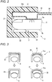
Fig. 2 is a sectional view showing a state in which a bag has inflated in a support tool belonging to the biological information acquisition system; -
Fig. 3 is a view for illustrating an effect which can be obtained by the configuration of the support tool; -
Fig. 4 is a graph illustrating an example of processing performed by a second light attenuation acquisition portion in the biological information acquisition system; -
Fig. 5 is a sectional view schematically showing a modification of the support tool; -
Fig. 6 is a sectional view schematically showing a modification of the support tool; -
Fig. 7 is a sectional view schematically showing an example of a tube connected to the support tool; -
Fig. 8 is a sectional view schematically showing another example of the tube connected to the support tool; -
Fig. 9 is a perspective view showing a first embodiment of the support tool; -
Fig. 10 is a perspective view showing a second embodiment of the support tool; -
Fig. 11 is a perspective view showing a third embodiment of the support tool; -
Fig. 12 is a perspective view showing a fourth embodiment of the support tool; -
Fig. 13 is a perspective view showing a fifth embodiment of the support tool; -
Fig. 14 is a sectional view taken along a line XIV-XIV ofFig. 13 ; -
Fig. 15 is a perspective view showing a sixth embodiment of the support tool; and -
Fig. 16 is a perspective view showing a seventh embodiment of the support tool. - Embodiments of the present invention will be described below in detail by way of example with reference to the accompanying drawings. In the drawings used in the following description, scales are adjusted as appropriate for the purpose of illustrating each member in a recognizable size.
-
Fig. 1 is a diagram schematically showing a configuration of a biological information acquisition system 1 according to an embodiment of the present invention. The biological information acquisition system 1 includes asensor 2, asupport tool 3, and a biologicalinformation acquisition apparatus 4. - The
sensor 2 is configured to be mounted on afinger 5 of a subject and output a signal corresponding to biological information of the subject. - The
support tool 3 is a tool which is mounted on thefinger 5 of the subject on which thesensor 2 is mounted so as to support acquisition of the biological information. - The biological
information acquisition apparatus 4 includes aninformation acquisition part 41. Theinformation acquisition part 41 is configured to acquire the biological information of the subject based on the signal output from thesensor 2. - The biological
information acquisition apparatus 4 includes aninformation output part 42. Theinformation output part 42 is configured to output the information acquired by theinformation acquisition part 41. - The
support tool 3 includes afirst support 31. Thefirst support 31 is disposed on anail side 5a (an example of a first side) of thefinger 5 when thesupport tool 3 is mounted on the subject'sfinger 5. - The
support tool 3 includes asecond support 32. Thesecond support 32 is disposed on aventral side 5b (an example of a second side) of thefinger 5 when thesupport tool 3 is mounted on the subject'sfinger 5. That is, thesecond support 32 is disposed on the opposite side to thefirst support 31 with the interposition of thefinger 5 therebetween. - For example, the
first support 31 and thesecond support 32 are molded out of a hard resin. Thus, the relative position of thefirst support 31 with respect to thesecond support 32 is set not to change. - The
support tool 3 includes abag 33. Thebag 33 is made of a material softer than thefirst support 31 and thesecond support 32. For example, the material may be a soft resin, rubber, or the like. Thebag 33 is disposed along an innerperipheral face 31a of thefirst support 31. - In a state in which the
support tool 3 is mounted on the subject'sfinger 5, thesensor 2 is disposed between the subject'sfinger 5 and thesecond support 32 and between the subject'sfinger 5 and thebag 33. - The
support tool 3 includes a ventilation tube 34 (an example of a channel formation part). Theventilation tube 34 forms a ventilation channel (an example of a fluid channel) communicating with the inside of thebag 33. - The biological
information acquisition apparatus 4 includes apressure adjustment part 43. Thepressure adjustment part 43 is configured to adjust the volume of air inside thebag 33 through theventilation tube 34 to thereby adjust pressure applied to the subject'sfinger 5. - Specifically, the
pressure adjustment part 43 sends air into thebag 33 through theventilation tube 34 to thereby increase the volume of air inside thebag 33. Thus, as shown inFig. 2 , thebag 33 made of a soft material inflates to compress the subject'sfinger 5 together with thesensor 2. Due to this compression, blood in living tissues of the subject'sfinger 5 is removed. In order to remove the blood, the pressure applied to thefinger 5 is set to be not lower than maximum arterial blood pressure (about 200 mmHg) of the subject. - On the contrary, the
pressure adjustment part 43 releases the air inside thebag 33 through theventilation tube 34 to thereby reduce the volume of the air inside thebag 33. Thus, thebag 33 deflates to its original state shown inFig. 1 so that the compression state of the subject'sfinger 5 can be released. - The signal output from the
sensor 2 changes in accordance with the compression state and the compression release state. Theinformation acquisition part 41 of the biologicalinformation acquisition apparatus 4 acquires biological information of the subject based on the change of the output signal. The information acquired thus is provided to a user such as a medical personnel through theinformation output part 42. - According to the aforementioned configuration, the
bag 33 made of the soft material inflates to compress the subject'sfinger 5. Accordingly, uniform compression force can be applied non-locally. Accordingly, even if the relative position of thesupport tool 3 with respect to the subject'sfinger 5 changes whenever thesupport tool 3 is mounted, the influence of the change of the relative position on the compression state can be suppressed. - In addition, the
sensor 2 is mounted on the subject'sfinger 5 outside thebag 33. Therefore, the relative position of thesensor 2 with respect to the subject'sfinger 5 does not change in accordance with inflation and deflation of thebag 33. Accordingly, even if the relative position of thesupport tool 3 with respect to the subject'sfinger 5 changes whenever thesupport tool 3 is mounted, the influence of the change of the relative position on a detection result made by thesensor 2 can be suppressed. - In addition, a pressurized state can be set or released by only sending air into the
bag 33 or releasing air from thebag 33. Therefore, it is not necessary to build an actuator driving mechanism in thesupport tool 3. Accordingly, the size and weight of thesupport tool 3 can be reduced, and a burden imposed on the subject on whom thesupport tool 3 is mounted can be suppressed. Further, such asupport tool 3 can be provided at low cost. - As described above, according to the aforementioned configuration, a specific compression state can be reproduced easily when biological information is acquired with compression of living tissues. In this manner, the biological information of the subject can be acquired quantitatively and reproductively.
- The
sensor 2 includes alight emitter 21. Thelight emitter 21 is mounted on thenail side 5a of the subject'sfinger 5. Thelight emitter 21 is configured to emit first light having a first wavelength λ1 and second light having a second wavelength λ2. Thelight emitter 21 includes a light emitting device which emits red light having a wavelength of 660 nm as an example of the first wavelength λ1, and a light emitting device which emits infrared light having a wavelength of 940 nm as an example of the second wavelength λ2. Each of the light emitting devices emits light at a predetermined timing in accordance with a control signal issued from theinformation acquisition part 41 of the biologicalinformation acquisition apparatus 4. For example, the light emitting device may be a light emission diode (LED) or a laser diode. The first light and the second light emitted thus are incident on the subject'sfinger 5 separately. - The
sensor 2 includes alight receiver 22. Thelight receiver 22 is mounted on theventral side 5b of the subject'sfinger 5. Thelight receiver 22 is disposed in a position where both the first light and the second light transmitted through thefinger 5 can be received. Thelight receiver 22 is configured to output a first signal S1 corresponding to an intensity I1 of the received first light and a second signal S2 corresponding to an intensity I2 of the received second light. For example, an element functioning as thelight receiver 22 may be a photodiode. The signals S1 and S2 output from thelight receiver 22 are input to theinformation acquisition part 41 of the biologicalinformation acquisition apparatus 4. - The
information acquisition part 41 may include a first lightattenuation acquisition portion 411. The first lightattenuation acquisition portion 411 is configured to acquire a light attenuation A1 of the first light based on the first signal S1 and acquire a light attenuation A2 of the second light based on the second signal S2. The light attenuations A1 and A2 are calculated respectively as ratios of quantities of received lights of the first signal S1 and the second signal S2 at a time instant (e.g. during compression of the living tissues) to quantities of received lights of the first signal S1 and the second signal S2 at another time instant (e.g. before compression of the living tissues). The light attenuations A1 and A2 are expressed by the following expressions respectively.

- The
information acquisition part 41 may include a second lightattenuation acquisition portion 412. The second lightattenuation acquisition portion 412 is configured to acquire a blood-based light attenuation Ab based on the light attenuations A1 and A2 of the first light and the second light acquired by the first lightattenuation acquisition portion 411. Specifically, the second lightattenuation acquisition portion 412 is configured to acquire the blood-based light attenuation Ab based on a difference between the light attenuation A1 and the light attenuation A2. The principle of this processing will be described below in detail. - When the
bag 33 is inflated to compress the subject'sfinger 5, thicknesses of the living tissues change. Each of changes A of the light attenuations generated at that time is caused by a change in thickness of blood and a change in thickness of non-blood tissues. The fact can be expressed by the following expressions.

- Since wavelength dependency of the non-blood tissues is ignorable, Z1 can be regarded as being equal to Z2. When the expression (3) is subtracted from the expression (4) here, the following expression is obtained.

- Only information about the blood is contained on the right side. Accordingly, when the difference between the light attenuation A1 and the light attenuation A2 is taken, the blood-based light attenuation Ab can be obtained.
-
Fig. 4 is a graph showing temporal change of the light attenuation A1, the light attenuation A2 and the blood-based light attenuation Ab (=A2-A1) in the case where thefinger 5 is compressed from above thesensor 2. - Even after the compression is released, the values of the light attenuations A1 and A2 do not return to levels prior to the start of the compression. Therefore, it is known that deformation of the non-blood tissues influences the values of the light attenuations A1 and A2. On the other hand, it is known that after the compression is released, the difference value (A2-A1) between the light attenuations, i.e. the blood-based light attenuation Ab converges at a level prior to the start of the compression. That is, the influence of the deformation of the non-blood tissues can be removed only by a simple arithmetic operation of taking a difference between the light attenuations obtained when the tissues are irradiated with the lights having the different wavelengths.
- As shown in
Fig. 1 , theinformation acquisition part 41 may include a capillary refilltime specifying portion 413. The capillary refilltime specifying portion 413 is configured to specify a capillary refill time into the living tissues of thefinger 5 based on a temporal change of the blood-based light attenuation Ab (= A2-A1) generated due to the compression of the subject'sfinger 5 by thebag 33 and obtained by the second lightattenuation acquisition portion 412. Specifically, a proper threshold is determined so that, based on the threshold, it is possible to judge that the blood-based light attenuation Ab somewhat approximates to the level prior to the start of the compression. A time (T inFig. 4 ) from a time point at which the compression is released to a time point at which the blood-based light attenuation Ab reaches the threshold is specified as the capillary refill time. Thus, the capillary refill time can be specified accurately without the influence of the deformation of the non-blood tissues caused by a difference in the degree of the compression. - The
information acquisition part 41 inputs a signal ST to theinformation output part 42. The signal ST indicates the capillary refill time T specified by the capillary refilltime specifying portion 413. Theinformation output part 42 outputs the capillary refill time T in a suitable form corresponding to the signal ST. For example, the output form may be an indication based on at least one of a numerical value, a color and a symbol corresponding to the capillary refill time T, output of sound corresponding to the capillary refill time T, or the like. - According to the aforementioned configuration, the
bag 33 can be inflated to reproduce the specific compression state of the subject'sfinger 5 easily. Accordingly, the capillary refill time of the subject can be measured quantitatively and reproducibly. - The
light emitter 21 of thesensor 2 may be configured to emit third light having a third wavelength λ3 in addition to the first light having the first wavelength λ1 and the second light having the second wavelength λ2. The first wavelength λ1 and the second wavelength λ2 are wavelengths which are absorbed by hemoglobin, whereas the third wavelength λ3 is set as a wavelength at which absorption by water is larger than absorption by hemoglobin. For example, the third wavelength λ3 may be 1,300 nm. In this case, thelight receiver 22 of thesensor 2 is configured to output a third signal S3 in accordance with an intensity of the third light transmitted through the subject'sfinger 5. - In the example, the
information acquisition part 41 of the biologicalinformation acquisition apparatus 4 is configured to acquire information about the non-blood living tissues of the subject based on the third signal S3 output by thelight receiver 22. Specifically, the first lightattenuation acquisition portion 411 acquires a light attenuation A3 of the third light based on the third signal S3. The light attenuation A3 expresses information about light absorption by the blood and water of the non-blood living tissues. Therefore, when a value of the light attenuation A3 does not return to the level prior to the start of the compression even after the compression of the subject'sfinger 5 attained by the inflation of thebag 33 is released, presence of edema is suspected. - According to the aforementioned configuration, the
bag 33 can be inflated to reproduce the specific compression state of the subject'sfinger 5 easily. Accordingly, diagnosis of edema can be performed reproducibly. - The
information acquisition part 41 may be configured to acquire information about the non-blood living tissues of the subject also based on the first signal S1 and the second signal S2 in addition to the third signal S3. Specifically, with reference to the temporal change of the blood-based light attenuation Ab (= A2-A1) which has been acquired by the second lightattenuation acquisition portion 412, it is possible to grasp to what extent the blood has returned to the living tissues after the compression preformed by thebag 33 is released. For example, assume that presence of edema has been confirmed based on the light attenuation A3. Even in this case, it is possible to estimate the edema to be mild when the return quantity of the blood is sufficient. - According to the aforementioned configuration, the
bag 33 can be inflated to reproduce the specific compression state of the subject'sfinger 5 easily. Accordingly, the degree of edema can be performed quantitatively and reproducibly. - The
light emitter 21 of thesensor 2 may be configured to emit light having N kinds of wavelengths that are different from one another, N being an integer equal to or greater than 3. For example, thelight emitter 21 may be configured to emit first light having a first wavelength λ1, second light having a second wavelength λ, third light having a third wavelength λ3, and fourth light having a fourth wavelength λ4. In this case, thelight emitter 21 includes a light emitting device which emits red light having a wavelength of 660 nm as an example of the first wavelength λ1, a light emitting device which emits infrared light having a wavelength of 940 nm as an example of the second wavelength λ2, a light emitting device which emits infrared light having a wavelength of 810 nm as an example of the third wavelength λ3, and a light emitting device which emits red light having a wavelength of 620 nm or 635 nm as an example of the fourth wavelength λ4. The respective light emitting devices emit the lights at predetermined timings in accordance with a control signal issued from theinformation acquisition part 41 of the biologicalinformation acquisition apparatus 4. For example, each of the light emitting devices may be a light emission diode (LED) or a laser diode. The first light, the second light, the third light and the fourth light emitted thus are incident on the subject'sfinger 5 separately. - In the example, the
light receiver 22 is configured to output N kinds of signals in accordance with intensities of the N kinds of light transmitted through the subject'sfinger 5. Specifically, thelight receiver 22 is disposed in a position where the first light, the second light, the third light and the fourth light transmitted through thefinger 5 can be received. Thelight receiver 22 is configured to output a first signal S1 corresponding to an intensity I1 of the received first light, a second signal S2 corresponding to an intensity I2 of the received second light, a third signal S3 corresponding to an intensity I3 of the received third light, and a fourth signal S4 corresponding to an intensity I4 of the received fourth light. For example, an element functioning as thelight receiver 22 may be a photodiode. The signals S1, S2, S3 and S4 output from thelight receiver 22 are input to theinformation acquisition part 41 of the biologicalinformation acquisition apparatus 4. - In the example, the first light
attenuation acquisition portion 411 is configured to acquire N kinds of light attenuations based on the N kinds of signals output by thelight receiver 22. Specifically, the first lightattenuation acquisition portion 411 is configured to acquire a first light attenuation A1 of the first light based on the first signal S1, acquire a second light attenuation A2 of the second light based on the second signal S2, acquire a third light attenuation A3 of the third light based on the third signal S3, and acquire a fourth light attenuation A4 of the fourth light based on the fourth signal S4. The light attenuations A1, A2, A3 and A4 are calculated respectively as ratios of quantities of received lights of the first signal S1, the second signal S2, the third signal S3 and the fourth signal S4 at a time instant (e.g. during compression of the living tissues) to quantities of received lights of the first signal S1, the second signal S2, the third signal S3 and the fourth signal S4 at another time instant (e.g. before compression of the living tissues). The light attenuations A1, A2, A3 and A4 are expressed by the following expressions respectively.


- In this example, the second light
attenuation acquisition portion 412 is configured to acquire at most N-1 kinds of blood-based light attenuations based on at most N-1 kinds of combinations of two light attenuations selected from the N kinds of light attenuations acquired by the first lightattenuation acquisition portion 411. Specifically, the second lightattenuation acquisition portion 412 is configured to acquire a blood-based light attenuation based on the light attenuations A1 and A2 of the first light and the second light acquired by the first lightattenuation acquisition portion 411, a blood-based light attenuation based on the light attenuations A2 and A3 of the second light and the third light, and further a blood-based light attenuation based on the light attenuations A2 and A4 of the second light and the fourth light. More specifically, the second lightattenuation acquisition portion 412 is configured to acquire a blood-based light attenuation Ab21 based on a different between the light attenuation A2 and the light attenuation A1, acquire a blood-based light attenuation Ab23 based on a different between the light attenuation A2 and the light attenuation A3, and acquire a blood-based light attenuation Ab24 based on a different between the light attenuation A2 and the light attenuation A4. The principle of this processing will be described below in detail. - When the
bag 33 is inflated to compress the subject'sfinger 5, thicknesses of the living tissues change. Each of changes A of the light attenuations generated at that time is caused by a change in thickness of blood and a change in thickness of non-blood tissues. The fact can be expressed by the following expressions.


- Since wavelength dependency of the non-blood tissues is ignorable, Z1, Z2, Z3 and Z4 can be regarded as being equal to one another. When the expression (9) is subtracted from the expression (10), the expression (11) is subtracted from the expression (10), and the expression (12) is subtracted from the expression (10) here, the following expressions are obtained.


- Only information about the blood is contained on the right side. Accordingly, when the difference between the light attenuation A2 and the light attenuation A1, the difference between the light attenuation A2 and the light attenuation A3, and the difference between the light attenuation A2 and the light attenuation A4 are taken, the blood-based light attenuations Ab21, Ab23 and Ab24 can be obtained.
- Next, when the expression (13) is divided by the expression (14) and the expression (13) is divided by the expression (15), the items Hb and Db are removed, and the following expressions are obtained.


Fig. 4 . - From the above description, it is know that when the lights having at least four wavelengths are used to measure the blood-based light attenuations Ab21, Ab23 and Ab24, an O2Hb concentration, an RHb concentration, and a COHb concentration in the blood can be specified quantitatively through the expressions (16) to (21).
- As shown in
Fig. 1 , theinformation acquisition part 41 of the biologicalinformation acquisition apparatus 4 may include a blood substanceconcentration specifying portion 414. The blood substanceconcentration specifying portion 414 is configured to specify at most N-1 kinds of blood substance concentrations based on the at most N-1 kinds of blood-based light attenuations acquired by the second lightattenuation acquisition portion 412. That is, the blood substanceconcentration specifying portion 414 is configured to specify the O2Hb concentration, the RHb concentration, and the COHb concentration based on the aforementioned principle. Also when COHb is replaced by MetHb, similar measurement can be made. - The
information acquisition part 41 inputs a signal SC to theinformation output part 42. The signal SC indicates each of the blood substance concentrations (the O2Hb concentration, the RHb concentration, and the COHb concentration or the MetHB concentration) specified by the blood substanceconcentration specifying portion 414. Theinformation output part 42 outputs the blood substance concentration in a suitable form corresponding to the signal SC. For example, the output form may be an indication based on at least one of a numerical value, a color and a symbol corresponding to the blood substance concentration, output of sound corresponding to the blood substance concentration, or the like. - When the number of wavelengths to be used is set at 5, four hemoglobin concentrations can be obtained. For example, an O2Hb concentration, an RHb concentration, a COHb concentration and an MetHb concentration can be obtained simultaneously. When one of 620 nm and 635 nm is set as the fourth wavelength λ4, the other of 620 nm and 635 nm can be used as an example of the fifth wavelength λ5.
- When the number of wavelengths to be used is at least 3, the blood substance
concentration specifying portion 414 can specify a blood oxygen saturation as an example of the blood substance concentration. The principle thereof will be described specifically. - (E2-E1) and (E2-E3) in the expression (16) are functions of the blood oxygen saturation S. Extinction Coefficients E1, E2, E3 will be expressed by the following expressions respectively.


- From the above description, when the lights having at least three wavelengths are used to measure the blood-based light attenuations Ab21, Ab23 and Ab24, the blood oxygen saturation S can be specified quantitatively through the expression (16) and the expressions (23) to (25). The blood substance
concentration specifying portion 414 may be configured to specify the blood oxygen saturation S based on this principle. - The expression "at most (N-1)" used in the aforementioned description intends to include the following case. In the case where, for example, the
light emitter 21 is configured to emit lights having five wavelengths which are different from one another, it is not necessary to always obtain four blood substance concentrations. Configuration may be made so that thelight emitter 21 configured thus is used to obtain three blood substance concentrations or less. - According to the aforementioned configuration, the
bag 33 can be inflated to reproduce a specific compression state of the subject'sfinger 5 easily. Accordingly, the blood substance concentrations of the subject can be measured quantitatively and reproductively. - Here, the
information output part 42 may be configured to output the blood substance concentrations in a state in which the subject'sfinger 5 is not compressed by thebag 33. Specifically, theinformation acquisition part 41 monitors the operation of thepressure adjustment part 43 for inflating or deflating thebag 33 to thereby grasp whether the subject'sfinger 5 is in a compression state or not. Since values of pulsation-borne blood substance concentrations cannot be specified in the compression state, the values can be specified only after the compression state is released. Accordingly, it is not preferable to present, to a user, the values of the blood substance concentrations in the compression state in real time. Therefore, theinformation output part 42 may be configured to suspend outputting the blood substance concentrations as long as it is determined by theinformation acquisition part 41 that the subject'sfinger 5 has been compressed by thebag 33. For example, the measurement values of the blood substance concentrations are prevented from being displayed in the biologicalinformation acquisition apparatus 4. - According to this configuration, effective measurement values can be always presented to the user while the blood substance concentrations of the subject can be measured quantitatively and reproducibly.
- Alternatively, the
information output part 42 may be configured to maintain the values output prior to the operation of thepressure adjustment part 43 for pressurizing thebag 33, as long as it is determined by theinformation acquisition part 41 that the subject'sfinger 5 has been compressed by thebag 33. - According to this configuration, the measurement values per se are constantly output. Therefore, effective measurement values can be always presented to the user with a feeling of security while the blood substance concentrations of the subject can be measured quantitatively and reproducibly.
- As shown in
Fig. 1 , the biologicalinformation acquisition apparatus 4 may include apower supply 44. For example, thepower supply 44 is a battery. Thepower supply 44 feeds electric power to the respective parts of the biologicalinformation acquisition apparatus 4 which require electric power for operating. In addition thereto or in place thereof, thepower supply 44 may be configured to be capable of feeding electric power from an external commercial power supply to the respective parts of the biologicalinformation acquisition apparatus 4. - As shown in
Fig. 1 , thepressure adjustment part 43 may include amotor pump 431. Themotor pump 431 is operated by electric power fed from thepower supply 44. Themotor pump 431 can perform a pressurization operation for sending air into thebag 33 through theventilation tube 34, and a depressurization operation for removing the air inside thebag 33 through theventilation tube 34. - The
pressure adjustment part 43 controls themotor pump 431 to perform the pressurization operation to inflate thebag 33 to thereby compress the subject'sfinger 5. When, for example, the pressurization operation is performed for a fixed time, a compression state in which thefinger 5 is compressed by thebag 33 can be formed. Thepressure adjustment part 43 controls themotor pump 431 to perform the depressurization operation to deflate thebag 33. In this manner, the compression state can be released. - According to this configuration, the
bag 33 can be inflated to compress the subject'sfinger 5 automatically, so that a specific compression state can be reproduced easily. In this manner, the biological information of the subject can be acquired quantitatively and reproducibly. - As shown in
Fig. 1 , the biologicalinformation acquisition apparatus 4 may include apressure sensor 45. Thepressure sensor 45 is configured to detect internal pressure of thebag 33. Thepressure sensor 45 may directly detect the internal pressure of thebag 33, or may detect internal pressure of the ventilation channel (e.g. the inside of the ventilation tube 34) communicating thebag 33 and thepressure adjustment part 43 with each other to thereby indirectly detect the internal pressure of thebag 33. - In this case, the
pressure adjustment part 43 may be configured to adjust the volume of air inside the bag so that the internal pressure of thebag 33 can reach a target value based on a detection result of thepressure sensor 45. For example, thepressure adjustment part 43 controls themotor pump 431 to continue the pressurization operation until the internal pressure of thebag 33 reaches the target value. - Even when the
motor pump 431 performs a fixed operation, pressure applied to the subject'sfinger 5 may vary according to the shape of the subject'sfinger 5 or the mounting positions of thesensor 2 and thesupport tool 3. According to the aforementioned configuration, it is possible to grasp whether to what extent the pressure has been actually applied to the subject'sfinger 5. Therefore, a specific compression state can be reproduced easily regardless of the shape of the subject'sfinger 5 or the mounting positions of thesensor 2 and thesupport tool 3. In this manner, the biological information of the subject can be acquired more accurately and reproducibly. - As shown in
Fig. 1 , thesupport tool 3 may include aswitch 35. Theswitch 35 is configured to be actuated when the subject'sfinger 5 is put into thesupport tool 3. For example, theswitch 35 is provided in a space partitioned by thefirst support 31 and thesecond support 32. Theswitch 35 is configured to be actuated when the subject'sfinger 5 is disposed in a predetermined position in the space. For example, theswitch 35 may be a mechanical switch, an optical sensor, a temperature sensor, etc. - In this case, the biological
information acquisition apparatus 4 may include acontrol part 46. Thecontrol part 46 is configured to drive themotor pump 431 in accordance with the actuation of theswitch 35. - According to this configuration, the pressurization operation can be started by the
motor pump 431 automatically when thesupport tool 3 is mounted on the subject'sfinger 5. On the other hand, the pressurization operation can be prevented from being started by themotor pump 431 when thesupport tool 3 is not mounted in a proper position with respect to the subject'sfinger 5. Alternatively, the pressurization operation performed by themotor pump 431 can be suspended when thesupport tool 3 is displaced from the proper position with respect to the subject'sfinger 5 during measurement. - Accordingly, a specific compression state of the subject's
finger 5 can be reproduced more easily. In this manner, the biological information of the subject can be acquired more accurately and reproducibly. - As shown in
Fig. 1 , thepressure adjustment part 43 may include avalve 432. Thevalve 432 is provided between themotor pump 431 and theventilation tube 34. When themotor pump 431 is controlled to perform the pressurization operation with thevalve 432 being closed, a state in which air is compressed can be formed on an upstream side of thevalve 432. When thevalve 432 is opened in this state, the compressed air flows into thebag 33 at high speed so that a pressurized state can be formed rapidly. On the contrary, when themotor pump 431 is controlled to perform the depressurization operation with thevalve 432 being closed, a depressurized state can be formed on the upstream side of thevalve 432. When thevalve 432 is opened in this state, air inside thebag 33 can be released quickly. In this manner, delay of blood refill due to the residual pressure of thebag 33 can be suppressed. This configuration is particularly useful in the case where a small-sized motor pump 431 having relatively low air-sending capability is used. - The
control part 46 may be configured to operate thepressure adjustment part 43 at a predetermined interval. The interval may be variable suitably in accordance with a usage mode of the biologicalinformation acquisition apparatus 4. - According to this configuration, the
bag 33 can be inflated to compress the subject'sfinger 5 automatically whenever a predetermined time elapses. A specific compression state can be reproduced easily on this occasion. Therefore, for example, patient's therapy effect or deteriorating tendency of patient's condition during an operation or in an intensive care unit (ICU) can be checked automatically and accurately. - As shown in
Fig. 1 , the biologicalinformation acquisition apparatus 4 may include aswitch 47. Theswitch 47 is configured to start the operation of thepressure adjustment part 43. For example, theswitch 47 is a measurement start switch which is provided in an operating panel of the biologicalinformation acquisition apparatus 4. - In this case, the control part 46 (an example of a prohibition control part) may be configured to invalidate the operation of the
switch 47 unless a predetermined time elapses after compression of the subject'sfinger 5 by thebag 33 is released. For example, the predetermined time is set as a time which is required until blood removed from the living tissues of thefinger 5 due to the compression given by thebag 33 sufficiently returns to the living tissues due to the release of the compression. - After the compression of the subject's
finger 5 by thebag 33 is released, a certain amount of time is required until the blood returns to the living tissues of thefinger 5 to restore thefinger 5 to its original state. When theswitch 47 is operated prior to the restoration, biological information of the subject obtained through compression performed based on the operation may lack accuracy. According to the aforementioned configuration, next measurement can be prevented from being carried out before the subject'sfinger 5 which has been released from the compression is restored to its original state. Accordingly, the biological information of the subject can be acquired more accurately and reproducibly while a specific compression state of the subject'sfinger 5 can be reproduced easily. - The
control part 46 may be configured to be capable of changing the aforementioned predetermined time in accordance with the operation state of thepressure adjustment part 43. For example, assume that the aforementioned predetermined time is normally set as thirty seconds. Even in this case, setting can be made to invalidate the operation of theswitch 47 for five minutes after compression has been performed five times within three minutes. - When the compression is performed by the
bag 33 repeatedly, a burden imposed on the living tissues of the subject'sfinger 5 becomes large in spite of non-local pressure. According to the aforementioned configuration, the burden imposed on the subject can be suppressed while a specific compression state of the subject'sfinger 5 can be reproduced easily. - As shown in
Fig. 1 , the biologicalinformation acquisition apparatus 4 may include a powersupply monitoring part 48. The powersupply monitoring part 48 is configured to monitor power feeding performance from thepower supply 44 to themotor pump 431. The powersupply monitoring part 48 is configured to control thepressure adjustment part 43 to stop driving themotor pump 431 when the power feeding performance is lower than a predetermined value. For example, the circumstance that the power feeding capacity is lower than the predetermined value may be a case where the residual level of a battery is lower than the predetermined value, a case where a blackout occurred while the commercial power supply is in use, or the like. - When the
motor pump 431 is driven under a circumstance that power is fed insufficiently, a desired compression state of the subject'sfinger 5 may not be able to be obtained. According to the aforementioned configuration, a situation that measurement is made in this state to acquire inaccurate biological information of the subject can be avoided. Accordingly, the biological information of the subject can be acquired more accurately and reproducibly while a specific compression state of the subject'sfinger 5 can be reproduced easily. - As shown in
Fig. 1 , thepressure adjustment part 43 of the biologicalinformation acquisition apparatus 4 may include amanual adjustment mechanism 433 in addition to or in place of themotor pump 431. Themanual adjustment mechanism 433 is a mechanism configured to be capable of manually adjusting the volume of air inside thebag 33. For example, themanual adjustment mechanism 433 includes a check valve and an air-sending piece. The check valve may be provided in the middle of theventilation tube 34. For example, the air-sending piece may be a rubber ball, a syringe, etc. When the air-sending piece is operated, air is sent into thebag 33 through theventilation tube 34. Thus, thebag 33 inflates. In addition, deflation can be prevented by the check valve. When the compression state generated by thebag 33 has to be released, it will go well as long as the check valve is opened. - In the case of the configuration in which the
manual adjustment mechanism 433 is provided in place of themotor pump 431, the configuration of thepressure adjustment part 43 can be simplified, and the size and weight of the biologicalinformation acquisition apparatus 4 can be reduced. In the case of the configuration in which themanual adjustment mechanism 433 is provided in addition to themotor pump 431, biological information can be acquired manually even when the power feeding performance of thepower supply 44 to themotor pump 431 becomes insufficient. When thepower supply 44 is a battery, biological information can be acquired manually if necessary. As a result, electric power can be saved. Accordingly, the biological information of the subject can be measured in accordance with the circumstance while a specific compression state of the subject'sfinger 5 can be reproduced easily. - As shown in
Fig. 1 , the biologicalinformation acquisition apparatus 4 may include anaudio output part 49. Theaudio output part 49 is configured to output sound corresponding to the pressure applied to the subject'sfinger 5. Since the pressure corresponds to the internal pressure of thebag 33, theaudio output part 49 can use a detection result of theaforementioned pressure sensor 45. Alternatively, configuration may be made so that a pressure sensor which can more directly detect the pressure applied to the subject'sfinger 5 is provided separately in thesupport tool 3, and theaudio output part 49 uses the detection result of the pressure sensor. For example, theaudio output part 49 may output predetermined sound when the pressure applied to thefinger 5 reaches a predetermined value. Alternatively, theaudio output part 49 may output sound so that the sound volume or interval can change as the pressure applied to thefinger 5 increases. - According to this configuration, the user can easily grasp whether the subject's
finger 5 is in a compression state or not. Particularly in the case where pressure is given by thebag 33 manually, the user can use the sound output by theaudio output part 49, as a guide for forming a desired compression state. Accordingly, the biological information of the subject can be acquired accurately and reproducibly while a specific compression state of the subject'sfinger 5 can be reproduced more easily. - In each of the aforementioned configurations, the
light emitter 21 of thesensor 2 is mounted on thenail side 5a of the subject'sfinger 5, and thelight receiver 22 of thesensor 2 is mounted on theventral side 5b of thefinger 5. However, thelight emitter 21 may be mounted on theventral side 5b of thefinger 5 and thelight receiver 22 may be mounted on thenail side 5a of thefinger 5. - In each of the aforementioned configurations, light emitted from the
light emitter 21 and transmitted through the subject'sfinger 5 is incident on thelight receiver 22. However, anoptical sensor 2A may be used alternatively, as shown inFig. 5 . In theoptical sensor 2A, both alight emitter 21 and alight receiver 22 are mounted on the same side of the subject'sfinger 5, and light emitted from thelight emitter 21 and reflected on the subject'sfinger 5 is incident on thelight receiver 22. In the example ofFig. 5 , theoptical sensor 2A is mounted on theventral side 5b of thefinger 5. However, theoptical sensor 2A may be mounted on thenail side 5a of thefinger 5. - In each of the aforementioned configurations, the
support tool 3 is mounted on thefinger 5 of the subject on which thesensor 2 is mounted. However, as shown inFig. 6 , thesupport tool 3 may be configured such that thesensor 2 is attached to thesupport tool 3 in advance. Thelight emitter 21 and thereception part 22 of thesensor 2 are disposed at at least one of between the subject'sfinger 5 and thebag 33 and between the subject'sfinger 5 and thesecond support 32. In the example ofFig. 6 , thelight emitter 21 is disposed on an outer face of thebag 33 and thelight receiver 22 is disposed on an inner peripheral face of thesecond support 32. - According to this configuration, biological information can be acquired by only an operation of mounting the
support tool 3 on the subject'sfinger 5. Accordingly, the biological information of the subject can be acquired simply and reproducibly while a specific compression state of the subject'sfinger 5 can be reproduced easily. - As shown in
Fig. 1 , thelight emitter 21 of thesensor 2 is connected to theinformation acquisition part 41 of the biologicalinformation acquisition apparatus 4 through asignal line 51. Thelight mission part 21 of thesensor 2 is connected to theinformation acquisition part 41 of the biologicalinformation acquisition apparatus 4 through asignal line 52. When thesupport tool 3 includes theswitch 35, theswitch 35 is connected to thecontrol part 46 of the biologicalinformation acquisition apparatus 4 through asignal line 53. Thesupport apparatus 3 and the biologicalinformation acquisition apparatus 4 may be connected by atube 60 higher in softness than thefirst support 31 and thesecond support 32 of thesupport tool 3. A configuration example of such atube 60 will be shown inFig. 7 . -
Fig. 7 shows a section taken along a direction perpendicular to an extension direction of thetube 60. Thetube 60 includes aventilation channel 61 and a signalline housing part 62. Theventilation channel 61 is a part which functions as theventilation tube 34 and through which thepressure adjustment part 43 of the biologicalinformation acquisition apparatus 4 and thebag 33 of thesupport tool 3 communicate with each other. The signalline housing part 62 is a part which houses the signal lines 51, 52, 53. - Alternatively, the
support apparatus 3 and the biologicalinformation acquisition apparatus 4 may be connected to each other by atube 60A shown inFig. 8. Fig. 8 shows a section taken along a direction perpendicular to an extension direction of thetube 60A. Thetube 60A includes a pair ofventilation channels 61 and a signalline retention part 63. Theventilation channels 61 are parts which may function as theventilation tube 34 and through which thepressure adjustment part 43 of the biologicalinformation acquisition apparatus 4 and thebag 33 of thesupport tool 3 communicate with each other. Configuration may be made so that only one of theventilation channels 61 is provided. The signalline retention part 63 is a part which retains the signal lines 51, 52, 53 in a removable manner. - When the
tube 60 or thetube 60A is used, an electric system cable and a ventilation system hose can be combined into a single line. In this manner, dislocation of thesupport tool 3 due to body motion etc. of the subject can be suppressed, in comparison with a case where two lines may be displaced individually due to the body motion etc. Accordingly, a specific compression state of the subject'sfinger 5 can be reproduced more easily. Thus, the biological information of the subject can be acquired more reproducibly. - In the aforementioned configuration, the
pressure adjustment part 43 of the biologicalinformation acquisition apparatus 4 adjusts the volume of air inside thebag 33 through theventilation tube 34. However, a suitable fluid may be used as long as it can inflate or deflate thebag 33. In this case, theventilation tube 34 has a configuration in which the fluid can be circulated through theventilation tube 34. - Next, a specific configuration of the
support tool 3 belonging to the biological information acquisition system 1 configured in the aforementioned manner will be described. In the following description, the terms "front", "rear", "left", "right", "up" and "down" are used for the convenience of illustration, and do not limit an orientation or direction in an actual usage state. -
Fig. 9 shows asupport tool 3 according a first embodiment. In thesupport tool 3, a left end potion of afirst support 31 and a left end portion of asecond support 32 are connected by aconnection wall 36a, and a right end potion of thefirst support 31 and a right end portion of thesecond support 32 are connected by aconnection wall 36b. When thesupport tool 3 is mounted onto afinger 5 of a subject, thefinger 5 is surrounded by thefirst support 31, thesecond support 32 and theconnection walls - An inner
peripheral face 31 a of thefirst support 31 extends in the shape of an arc (the shape of an arc). Abag 33 is disposed to extend along the innerperipheral face 31a. One end of a ventilation tube 34 (only a part thereof is illustrated) is molded integrally with thebag 33. Thebag 33 which inflates due to air sent thereto from thepressure adjustment part 43 of the biologicalinformation acquisition apparatus 4 through theventilation tube 34 abuts against a peripheral part of the subject'sfinger 5 to thereby apply compression thereto. - According to this configuration, as shown in
Fig. 3 , a pressurized state can be formed by a smaller volume change of thebag 33, in comparison with a configuration in which a bag is mounted on a flat inner peripheral face. In other words, the pressurized state can be formed by use of thebag 33 having a smaller volume. That is, the pressurized state can be formed rapidly even by use of a smaller-sized air-sending mechanism. A similar effect can be obtained also when thebag 33 is deflated to release the pressurized state. Accordingly, the size of the apparatus can be reduced or cost can be suppressed while a specific compression state of the subject'sfinger 5 can be reproduced easily. - As shown in
Fig. 9 , thesupport tool 3 includesfixation assistance parts 37. Each of thefixation assistance parts 37 extends rearward from a rear end portion of thefirst support 31. Thefixation assistance part 37 is provided to extend along thefinger 5 in order to assist fixation of thesupport tool 3 to the subject'sfinger 5. - According to this configuration, a user can attach the
support tool 3 on the subject'sfinger 5 with thefixation assistance parts 37 as a guide. When thefixation assistance parts 37 are fixed to thefinger 5 by a tape etc. if necessary, dislocation of thesupport tool 3 with respect to thefinger 5 during measurement can be prevented. Accordingly, a specific compression state of thefinger 5 can be reproduced more easily. Thus, biological information of the subject can be acquired more reproducibly. -
Fig. 10 shows asupport tool 3A according to a second embodiment. Elements having identical or equivalent configurations or functions to those of thesupport tool 3 according to the first embodiment will be referred to by the same numerals correspondingly and respectively, and duplicate description thereof will be omitted. InFig. 10 , abag 33 and aventilation tube 34 are omitted from illustration. - In the
support tool 3A, a pair ofelastic pieces 37a (an example of elastic members) are provided on rear end portions of afixation assistance piece 37. When thesupport tool 3A is mounted on afinger 5 of a subject, theelastic pieces 37a hold a part of thefinger 5 to thereby surround the part of thefinger 5. - According to this configuration, the
support tool 3A can be fixed to the subject'sfinger 5 without requiring an auxiliary fixation piece such as a tape. In this manner, dislocation of thesupport tool 3 with respect to thefinger 5 during measurement can be prevented, so that a specific compression state of thefinger 5 can be reproduced more easily. Accordingly, biological information of the subject can be acquired more reproducibly. -
Fig. 11 shows asupport tool 3B according to a third embodiment. Elements having identical or equivalent configurations or functions to those of thesupport tool 3 according to the first embodiment will be referred to by the same numerals correspondingly and respectively, and duplicate description thereof will be omitted. - In the
support tool 3B, a front end portion of afirst support 31 and a front end portion of asecond support 32 are connected by aconnection wall 36c. When thesupport tool 3B is mounted on afinger 5 of a subject, thefinger 5 is disposed in a space partitioned by thefirst support 31, thesecond support 32 and theconnection wall 36c. The space is opened in a left/right direction. - That is, the whole periphery of the subject's
finger 5 does not have to be surrounded during acquisition of biological information. When a portion having relatively high rigidity is set to the necessary minimum, an increase in the weight of thesupport tool 3B can be suppressed. Accordingly, a burden imposed on the subject on whom thesupport tool 3B is mounted can be suppressed. -
Fig. 12 shows a support tool 3C according to a fourth embodiment. Elements having identical or equivalent configurations or functions to those of thesupport tool 3 according to the first embodiment will be referred to by the same numerals correspondingly and respectively, and duplicate description thereof will be omitted. - The support tool 3C includes a pressing
member 38. The pressingmember 38 is a member that resembles a finger of a living body. Specifically, the pressingmember 38 is made of a soft material that resembles a finger of a living body. The pressingmember 38 has a shape that ressembles a finger which has been compressed by a hand of a medical personnel. The pressingmember 38 is provided on an outer face of abag 33. When thebag 33 inflates due to air sent thereto from thepressure adjustment part 43 of the biologicalinformation acquisition apparatus 4 through aventilation tube 34, the pressingmember 38 abuts against afinger 5 of a subject. - According to this configuration, it is possible to form a more natural compression state which is similar to the compression heretofore performed by a hand of a medical personnel. Accordingly, biological information can be acquired more naturally while a specific compression state of the subject's
finger 5 can be reproduced easily. -
Fig. 13 andFig. 14 show asupport tool 3D according to a fifth embodiment.Fig. 14 is a longitudinal sectional view taken along a line XIV-XIV inFig. 13 . Elements having identical or equivalent configurations or functions to those of thesupport tool 3 according to the first embodiment will be referred to by the same numerals correspondingly and respectively, and duplicate description thereof will be omitted. - As shown in
Fig. 13 , thesupport tool 3D has afixation assistance part 37. Thefixation assistance part 37 is provided on a rear end portion of asecond support 32 and extends rearward. In addition, thesupport tool 3D includes achannel formation part 39. Thechannel formation part 39 is provided on an outer peripheral face of afirst support 31. Thechannel formation part 39 has aconnection portion 39a. As shown inFig. 14 , aventilation channel 39b is formed inside thechannel formation part 39. One end of theventilation channel 39b is opened in theconnection portion 39a. The other end of theventilation channel 39b communicates with the inside of thebag 33 mounted on an innerperipheral face 31 a of thefirst support 31. When one end of a not-shownventilation tube 34 is connected to theconnection portion 39a, a ventilation channel ranging from thepressure adjustment part 43 of the biologicalinformation acquisition apparatus 4 to thebag 33 is formed. - According to this configuration, the
support tool 3D can be attached to theventilation tube 34 removably. Thus, theventilation tube 34 does not have to be molded integrally with thebag 33 so that manufacturing cost of thesupport tool 3D can be suppressed. Accordingly, it is possible to meet a request to make only thesupport tool 3D disposable while reproducing a specific compression state of the subject'sfinger 5 easily. -
Fig. 15 shows asupport tool 3E according to a sixth embodiment. Elements having identical or equivalent configurations or functions to those of thesupport tool 3D according to the fifth embodiment will be referred to by the same numerals correspondingly and respectively, and duplicate description thereof will be omitted. - In the
support tool 3E, achannel formation part 39 is made rotatable around a central axis X within a plane perpendicular to the central axis X. The central axis X extends in an up/down direction of thesupport tool 3E. The central axis X extends along a portion where aventilation channel 39b extends in the up/down direction of thesupport tool 3E (seeFig. 14 ). Thus, thechannel formation part 39 is made movable relatively to afirst support 31. - In the
support tool 3E, aconnection portion 39a is made rotatable around a central axis Y within a plane perpendicular to the central axis Y. The central axis Y extends in a front/rear direction of thesupport tool 3E. The central axis Y extends along a portion where theventilation channel 39b extends in the front/rear direction of thesupport tool 3E (seeFig. 14 ). Thus, theconnection portion 39a is made movable relatively to thefirst support 31. - According to this configuration, even when a
ventilation tube 34 connected to theconnection portion 39a is displaced due to body motion of a subject, thechannel formation part 39 is displaced following the displacement of theventilation tube 34. Accordingly, dislocation of the support tool E due to the body motion can be suppressed. Accordingly, a specific compression state of afinger 5 of the subject can be reproduced more easily. Thus, biological information of the subject can be acquired more reproducibly. - The
channel formation part 39 and theconnection portion 39a may be configured such that one of them is movable relative to thefirst support 31. -
Fig. 16 shows asupport tool 3F according to a seventh embodiment. Elements having identical or equivalent configurations or functions to those of thesupport tool 3D according to the fifth embodiment will be referred to by the same numerals correspondingly and respectively, and duplicate description thereof will be omitted. - The
support tool 3F includes anelastic member 37b on a rear end portion of afixation assistance part 37. A throughhole 37c extending in a front/rear direction of thesupport tool 3F is formed in theelastic member 37b. Theelastic member 37b is made of a material which has elasticity and which is higher in softness than thefixation assistance part 37. - To attach the
support tool 3F on afinger 5 of a subject, thefinger 5 is first inserted into the throughhole 37c of theelastic member 37b. Thefinger 5 passes through theelastic member 37b while enlarging the throughhole 37c. As a result, thefinger 5 is disposed in a predetermined position opposed to abag 33. Theelastic member 37b retains thefinger 5 due to its own elasticity while surrounding a part of thefinger 5. - According to this configuration, the
support tool 3F can be fixed to the subject'sfinger 5 without requiring an auxiliary fixation piece such as a tape. Thus, dislocation of thesupport tool 3 with respect to thefinger 5 during measurement can be prevented, so that a specific compression state of thefinger 5 can be reproduced more easily. Accordingly, biological information of the subject can be acquired more reproducibly. - In the
support tool 3F, a throughhole 32a is formed in asecond support 32. The throughhole 32a communicates with a space where the subject'sfinger 5 is disposed. The position, shape and size of the throughholes 32a are determined to allow access to thefinger 5 of the subject on whom thesupport tool 3F is mounted. The access may be made by a rod-like jig or a user's finger. - According to this configuration, even in an emergency that the
pressure adjustment part 43 of the biologicalinformation acquisition apparatus 4 cannot function for some reason, the subject'sfinger 5 can be compressed by a user's hand so that biological information can be acquired. - The through
hole 32a may be formed in afirst support 31. In this case, thebag 33 is pressed against the subject'sfinger 5 by a rod-like jig or a user's finger. - Features described about each of the aforementioned embodiments may be combined suitably with configurations of other embodiments as long as the original configurations or functions of the other embodiments are not spoiled.
- The above description is for facilitating the understanding of the present invention, and does not limit the present invention. The present invention may be changed or modified without departing from the gist of the invention and it is apparent that their equivalents are also included in the invention.
- The biological
information acquisition apparatus 4 according to the aforementioned embodiment acquires a capillary refill time and blood substance concentrations of a subject as biological information. In other words, the support tool 3 (3A to 3F) according to each of the aforementioned embodiments is mounted on afinger 5 of the subject to support acquisition of the capillary refill time and the blood substance concentrations of the subject. However, the support tool 3 (3A to 3F) according to the invention can be applied to support of acquisition of all biological information which can be acquired by use of the sensor of a type which can be mounted on the subject'sfinger 5. For example, the biological information may be a heart rate, body temperature, etc. - In the support tool 3 (3A to 3F) according to each of the aforementioned embodiments, the
bag 33 is disposed along the innerperipheral face 31a of thefirst support 31 disposed on thenail side 5a of the finger. However, the support tool 3 (3A to 3F) according to each of the aforementioned embodiments may have a configuration in which thefirst support 31 is disposed on theventral side 5b of thefinger 5. In this case, thebag 33 is disposed on theventral side 5b of thefinger 5, and thesecond support 32 is disposed on thenail side 5a of thefinger 5. In addition, the support tool 3 (3A to 3F) according to each of the aforementioned embodiments may have a configuration in which thefirst support 31 is disposed on one of the left and right sides of thefinger 5. In this case, thebag 33 is disposed on the one of the left and right sides of thefinger 5, and thesecond support 32 is disposed on an opposite side to thefirst support 31 with the interposition of thebag 33 therebetween. - In the support tool 3 (3A to 3F) according to each of the aforementioned embodiments, the whole of the
bag 33 is disposed along the innerperipheral face 31a of thefirst support 31. However, the support tool 3 (3A to 3F) according to each of the aforementioned embodiments may have a configuration in which at least a part of thebag 33 is disposed along the innerperipheral face 31a of thefirst support 31. In the case where, for example, thefirst support 31 is disposed on thenail side 5a of the subject'sfinger 5, a part of thebag 33 may be formed into a shape going around to theventral side 5b of thefinger 5. - In the embodiments illustrated so far, the functions of the
information acquisition part 41, thecontrol part 46, the powersupply monitoring part 48, the first lightattenuation acquisition portion 411, the second lightattenuation acquisition portion 412, the capillary refilltime specifying portion 413, and the blood substanceconcentration specifying portion 414 are achieved by software executed by cooperation between a processor and a memory which are connected communicably. For example, the processor may be a CPU or an MPU. For example, the memory may be an RAM or an ROM. However, at least one of the functions of theinformation acquisition part 41, thecontrol part 46, the powersupply monitoring part 48, the first lightattenuation acquisition portion 411, the second lightattenuation acquisition portion 412, the capillary refilltime specifying portion 413, and the blood substanceconcentration specifying portion 414 may be achieved by hardware such as a circuit element or by a combination of hardware and software. - The content of Japanese Patent Application No.
2014-047755 filed on March 11, 2014
Claims (27)
- A support tool to be mounted on a finger of a subject on which a sensor is mounted so as to support an acquisition of biological information of the subject, the support tool comprising:a first support to be disposed, when mounted, on a first side of the finger of the subject, the first support comprising an inner peripheral face;a second support to be disposed, when mounted, on a second side of the finger of the subject opposite to the first side, a relative position of the second support with respect to the first support being fixed;a bag made of a material softer than the first support and the second support, the bag being at least partially disposed along the inner peripheral face; anda channel formation part forming a fluid channel communicating with an inside of the bag,wherein the support tool is configured such that, when mounted, the sensor is disposed at at least one of between the finger of the subject and the bag and between the finger of the subject and the second support.
- The support tool according to claim 1, wherein the inner peripheral face extends in an arc shape.
- The support tool according to claim 1 or 2, wherein a pressing member that resembles a finger of a living body is provided on an outer face of the bag.
- The support tool according to any one of claims 1 to 3, wherein a fixation assistance part is provided on at least one of the first support and the second support to assist a fixation to the finger of the subject.
- The support tool according to claim 4, wherein the fixation assistance part comprises an elastic member that surrounds a part of the finger of the subject.
- The support tool according to any one of claims 1 to 5, wherein the channel formation part is provided on an outer peripheral face of the first support, the channel formation part comprising a connection portion to be connected to a tube communicating with the fluid channel.
- The support tool according to claim 6, wherein at least one of the channel formation part and the connection portion is movable relative to the first support.
- The support tool according to any one of claims 1 to 7, wherein a through hole allowing an access to the finger of the subject is formed through the first support or the second support.
- The support tool according to any one of claims 1 to 8, wherein the biological information includes at least one of a capillary refill time and a blood substance concentration.
- A support tool to be mounted on a finger of a subject to support an acquisition of biological information of the subject, the support tool comprising
a first support to be disposed, when mounted, on a first side of the finger of the subject, the first support comprising an inner peripheral face;
a second support to be disposed, when mounted, on a second side of the finger of the subject opposite to the first side, a relative position of the second support with respect to the first support being fixed;
a bag made of a material softer than the first support and the second support, the bag being at least partially disposed along the inner peripheral face;
a channel formation part forming a fluid channel communicating with an inside of the bag; and
a sensor that outputs a signal corresponding to the biological information of the subject, the sensor being disposed, when mounted, at at least one of between the finger of the subject and the bag and between the finger of the subject and the second support. - The support tool according to claim 10, comprising a tube connected to the channel formation part and having higher softness than the first support and the second support, wherein the tube comprises:a ventilation channel communicating with the channel formation part to form a part of the fluid channel; anda signal line housing part that houses a signal line electrically connected to the sensor.
- The support tool according to claim 10, comprising a tube connected to the channel formation part, the tube having higher softness than the first support and the second support, wherein the tube comprises:a ventilation channel communicating with the channel formation part to form a part of the fluid channel; anda signal line retention part that retains, in a removable manner, a signal line electrically connected to the sensor.
- The support tool according to any one of claims 10 to 12, wherein the biological information includes at least one of a capillary refill time and a blood substance concentration.
- A biological information acquisition system comprising:a support tool to be mounted on a finger of a subject;a sensor to be mounted on the finger of the subject to output a signal corresponding to biological information of the subject;an information acquisition part which acquires the biological information based on the signal output from the sensor; andan information output part which outputs the information acquired by the information acquisition part,wherein the support tool comprises:a first support to be disposed, when mounted, on a first side of the finger of the subject, the first support comprising an inner peripheral face;a second support to be disposed, when mounted, on a second side of the finger of the subject opposite to the first side, a relative position of the second support with respect to the first support being fixed;a bag made of a material softer than the first support and the second support, the bag being at least partially disposed along the inner peripheral face; anda channel formation part forming a fluid channel communicating with an inside of the bag,wherein the sensor is disposed, when the support tool is mounted, at at least one of between the finger of the subject and the bag and between the finger of the subject and the second support, and
wherein the biological information acquisition system further comprises a pressure adjustment part which adjusts, through the channel formation part, a volume of a fluid inside the bag to adjust a pressure applied to the finger of the subject. - The biological information acquisition system according to claim 14, wherein the pressure adjustment part comprises a motor pump.
- The biological information acquisition system according to claim 15, wherein the support tool comprises a switch which is actuated when mounted on the finger of the subject, and
wherein the biological information acquisition system further comprises a control part which drives the motor pump in accordance with the actuation of the switch. - The biological information acquisition system according to claim 15 or 16, comprising a power supply monitoring part which monitors a power feeding performance from a power supply to the motor pump,
wherein the power supply monitoring part controls the pressure adjustment part to stop driving the motor pump when the power feeding performance is lower than a predetermined value. - The biological information acquisition system according to any one of claims 14 to 17, wherein the pressure adjustment part includes a mechanism to manually adjust the volume of the fluid.
- The biological information acquisition system according to any one of claims 14 to 18, comprising:a pressure sensor which detects a pressure applied to the finger of the subject; andan audio output part which outputs a sound corresponding to the pressure.
- The biological information acquisition system according to any one of claims 14 to 19, wherein the sensor comprises:a light emitter which emits first light having a first wavelength, and second light having a second wavelength; anda light receiver which outputs a first signal and a second signal respectively in accordance with an intensity of the first light and an intensity of the second light which have been transmitted through or reflected on the finger of the subject, andwherein the information acquisition part comprises:a first light attenuation acquisition portion which acquires a light attenuation of the first light based on the first signal, and acquires a light attenuation of the second light based on the second signal;a second light attenuation acquisition portion which acquires a blood-based light attenuation based on the light attenuation of the first light and the light attenuation of the second light; anda capillary refill time specifying portion which specifies a capillary refill time in a tissue of the finger based on a temporal change of the blood-based light attenuation due to a compression of the finger of the subject by the bag.
- The biological information acquisition system according to claim 20, wherein the light emitter emits third light having a third wavelength,
wherein the light receiver outputs a third signal in accordance with an intensity of the third light which has been transmitted through or reflected on the finger of the subject,
wherein the first wavelength and the second wavelength are wavelengths which are absorbed by hemoglobin,
wherein the third wavelength is a wavelength at which an absorption by water is larger than an absorption by hemoglobin; and
wherein the information acquisition part acquires information on a non-blood tissue of the subject based on at least a temporal change of the third signal generated due to the compression of the finger of the subject by the bag. - The biological information acquisition system according to any one of claims 14 to 19, wherein the sensor comprises:a light emitter which emits lights having N kinds of wavelengths that are different from one another, N being an integer equal to or greater than 3; anda light receiver which outputs N kinds of signals in accordance with intensities of the N kinds of light which have been transmitted through or reflected on the finger of the subject; andwherein the information acquisition part comprises:a first light attenuation acquisition portion which acquires N kinds of light attenuations based on the N kinds of signals;a second light attenuation acquisition portion which acquires at most N-1 kinds of blood-based light attenuations based on at most N-1 kinds of combinations of two light attenuations selected from the N kinds of light attenuations; anda blood substance concentration specifying portion which specifies at most N-1 kinds of blood substance concentrations based on the at most N-1 kinds of blood-based light attenuations.
- The biological information acquisition system according to claim 22, wherein the information output part outputs the blood substance concentrations in a state in which the finger of the subject is not compressed by the bag,
wherein, while the finger of the subject is being compressed by the bag, the information output part either suspends outputting the blood substance concentrations or keeps pre-pressurization output values of the blood substance concentrations. - The biological information acquisition system according to any one of claims 14 to 23, comprising a control part which operates the pressure adjustment part at a predetermined interval.
- The biological information acquisition system according to any one of claims 14 to 24, comprising a switch which starts an operation of the pressure adjustment part; and
a prohibition control part which invalidates an operation of the switch until a predetermined time elapses after the compression of the finger of the subject by the bag is released. - The biological information acquisition system according to claim 25, wherein the predetermined time is variable based on an operating state of the pressure adjustment part.
- The biological information acquisition system according to any one of claims 14 to 26, comprising a pressure sensor which detects an internal pressure of the bag,
wherein the pressure adjustment part adjusts the volume of the fluid inside the bag based on a detection result of the pressure sensor so that the internal pressure becomes a target value.
Applications Claiming Priority (2)
| Application Number | Priority Date | Filing Date | Title |
|---|---|---|---|
| JP2014047755 | 2014-03-11 | ||
| PCT/JP2015/055765 WO2015137151A1 (en) | 2014-03-11 | 2015-02-27 | Support tool and biological information acquisition system |
Publications (2)
| Publication Number | Publication Date |
|---|---|
| EP3117769A1 true EP3117769A1 (en) | 2017-01-18 |
| EP3117769A4 EP3117769A4 (en) | 2017-10-25 |
Family
ID=54071599
Family Applications (1)
| Application Number | Title | Priority Date | Filing Date |
|---|---|---|---|
| EP15761528.7A Withdrawn EP3117769A4 (en) | 2014-03-11 | 2015-02-27 | Support tool and biological information acquisition system |
Country Status (4)
| Country | Link |
|---|---|
| US (1) | US20170014075A1 (en) |
| EP (1) | EP3117769A4 (en) |
| JP (1) | JP6554459B2 (en) |
| WO (1) | WO2015137151A1 (en) |
Cited By (1)
| Publication number | Priority date | Publication date | Assignee | Title |
|---|---|---|---|---|
| EP3545826A1 (en) * | 2018-03-30 | 2019-10-02 | Nihon Kohden Corporation | Support tool |
Families Citing this family (7)
| Publication number | Priority date | Publication date | Assignee | Title |
|---|---|---|---|---|
| BR112017012448A2 (en) * | 2014-12-15 | 2018-01-02 | Koninklijke Philips Nv | capillary refill time measuring device, and method for measuring capillary refill time |
| CN205612476U (en) | 2016-03-09 | 2016-10-05 | 潘卫江 | Multisection dactylotheca formula blood oxygen probe |
| WO2019031527A1 (en) * | 2017-08-08 | 2019-02-14 | 国立大学法人千葉大学 | Crt measurement device |
| KR102608643B1 (en) * | 2018-02-05 | 2023-12-05 | 삼성디스플레이 주식회사 | Electronic device |
| JP7368801B2 (en) * | 2019-06-26 | 2023-10-25 | 国立大学法人千葉大学 | measuring device |
| JP2021007675A (en) * | 2019-07-02 | 2021-01-28 | 日本光電工業株式会社 | Medical photometer |
| JP7240014B2 (en) * | 2021-06-15 | 2023-03-15 | 合同会社画像技術研究所 | Biological information measuring method, biological information measuring program, and biological information measuring device |
Family Cites Families (22)
| Publication number | Priority date | Publication date | Assignee | Title |
|---|---|---|---|---|
| JPH0342893Y2 (en) * | 1985-11-25 | 1991-09-09 | ||
| JPH0626540B2 (en) * | 1985-04-12 | 1994-04-13 | オムロン株式会社 | Pulse wave detector |
| JPS63274845A (en) * | 1987-05-06 | 1988-11-11 | Fuji Photo Film Co Ltd | Densitometer |
| US5511546A (en) * | 1993-09-20 | 1996-04-30 | Hon; Edward H. | Finger apparatus for measuring continuous cutaneous blood pressure and electrocardiogram electrode |
| US5638816A (en) * | 1995-06-07 | 1997-06-17 | Masimo Corporation | Active pulse blood constituent monitoring |
| US6248064B1 (en) * | 1998-05-26 | 2001-06-19 | Ineedmd.Com,Inc. | Tele-diagnostic device |
| JP3035663B1 (en) * | 1998-12-02 | 2000-04-24 | エヌイーシー・メディカルシステムズ株式会社 | Cuff block for finger arterial blood pressure monitor |
| IL130939A (en) * | 1999-07-14 | 2005-11-20 | Itamar Medical Ltd | Probe devices particularly useful for non-invasivedetection of medical conditions |
| JP2008194488A (en) * | 1999-11-30 | 2008-08-28 | Nippon Koden Corp | Apparatus for determining concentration of hemoglobin |
| EP1404215B1 (en) * | 2001-06-20 | 2007-08-15 | Purdue Research Foundation | Body-member-illuminating pressure cuff for use in optical noninvasive measurement of blood parameters |
| JP4284674B2 (en) * | 2003-01-31 | 2009-06-24 | 日本光電工業株式会社 | Absorbent concentration measuring device in blood |
| JP4186903B2 (en) * | 2004-10-06 | 2008-11-26 | 日本電信電話株式会社 | Ear blood pressure monitor |
| JP2006280790A (en) * | 2005-04-04 | 2006-10-19 | Nippon Telegr & Teleph Corp <Ntt> | Blood pressure monitor and method of measuring blood pressure |
| JP4617439B2 (en) * | 2005-10-31 | 2011-01-26 | コニカミノルタセンシング株式会社 | Biological information measuring device |
| JP2008206900A (en) * | 2007-02-28 | 2008-09-11 | Nippon Seimitsu Sokki Kk | Blood fluidity evaluation device |
| JP2009066199A (en) * | 2007-09-13 | 2009-04-02 | Citizen Holdings Co Ltd | Sphygmomanometer cuff |
| WO2010082444A1 (en) * | 2009-01-13 | 2010-07-22 | コニカミノルタセンシング株式会社 | Cover member, probe, and living body information measuring device using probe |
| JP2011067238A (en) * | 2009-09-24 | 2011-04-07 | Mitsuba Corp | Health support device |
| JP5687994B2 (en) * | 2010-11-09 | 2015-03-25 | 日本光電工業株式会社 | Biological signal measuring apparatus and biological signal measuring method |
| US20130253332A1 (en) * | 2012-03-20 | 2013-09-26 | Nellcor Puritan Bennett Llc | Tissue interface systems for application of optical signals into tissue of a patient |
| US20150327809A1 (en) * | 2012-12-06 | 2015-11-19 | Konica Minolta, Inc. | Biological information measuring device, measuring unit of biological information measuring device, finger accommodating unit of biological information measuring device, and pulse oxymeter |
| JP6200216B2 (en) * | 2013-06-13 | 2017-09-20 | 日本光電工業株式会社 | Biosignal measurement system, biosignal measurement device, and control program for biosignal measurement device |
-
2015
- 2015-02-27 EP EP15761528.7A patent/EP3117769A4/en not_active Withdrawn
- 2015-02-27 US US15/125,016 patent/US20170014075A1/en not_active Abandoned
- 2015-02-27 JP JP2016507446A patent/JP6554459B2/en active Active
- 2015-02-27 WO PCT/JP2015/055765 patent/WO2015137151A1/en active Application Filing
Cited By (1)
| Publication number | Priority date | Publication date | Assignee | Title |
|---|---|---|---|---|
| EP3545826A1 (en) * | 2018-03-30 | 2019-10-02 | Nihon Kohden Corporation | Support tool |
Also Published As
| Publication number | Publication date |
|---|---|
| JP6554459B2 (en) | 2019-07-31 |
| JPWO2015137151A1 (en) | 2017-04-06 |
| EP3117769A4 (en) | 2017-10-25 |
| US20170014075A1 (en) | 2017-01-19 |
| WO2015137151A1 (en) | 2015-09-17 |
Similar Documents
| Publication | Publication Date | Title |
|---|---|---|
| EP3117769A1 (en) | Support tool and biological information acquisition system | |
| EP2762074B1 (en) | Biological signal measuring system and biological signal measuring apparatus | |
| US10098552B2 (en) | Blood pressure measurement device | |
| EP1263315B1 (en) | A probe for use in non-invasive measurements of blood related parameters | |
| US7386336B2 (en) | Method and system for use in non-invasive optical measurements of blood parameters | |
| USRE44875E1 (en) | Active pulse blood constituent monitoring | |
| US7239905B2 (en) | Active pulse blood constituent monitoring | |
| US8700116B2 (en) | Sensor system with pressure application | |
| US20170290537A1 (en) | Capillary refill time diagnostic apparatus and methods | |
| US20110023575A1 (en) | Non-invasive sensor calibration device | |
| JP2003275192A (en) | Blood analyzer | |
| US10561366B2 (en) | Measuring system and method for evaluating condition of patient | |
| US10117585B2 (en) | Sensor and biological signal measuring system | |
| JP5864639B2 (en) | measuring device | |
| EP2465420A2 (en) | Method and system for use in non-invasive optical measurements of blood parameters | |
| US20180103873A1 (en) | Device, system and method for evaluating the microcirculation of blood in a tissue | |
| US9597025B2 (en) | Biological signal measuring system and biological signal measuring apparatus | |
| US20180206789A1 (en) | Extremity cuff such as a finger cuff, a method and a computer program product | |
| JPH10314151A (en) | Measuring probe for absorption matter density measuring instrument | |
| US20130131466A1 (en) | Tool for screening for a defect, such as peripheral arterial disease | |
| JP6622861B2 (en) | Measuring system and measuring device | |
| US20230263418A1 (en) | Handheld non-invasive compartment syndrome detector | |
| WO2023235546A1 (en) | Apparatus and methods for measuring blood pressure and other vital signs via a finger | |
| EP4076185A1 (en) | A bioanalyte monitoring device | |
| CN114126483A (en) | Pressure cuff for use in a non-invasive blood pressure measurement device |
Legal Events
| Date | Code | Title | Description |
|---|---|---|---|
| PUAI | Public reference made under article 153(3) epc to a published international application that has entered the european phase |
Free format text: ORIGINAL CODE: 0009012 |
|
| 17P | Request for examination filed |
Effective date: 20161007 |
|
| AK | Designated contracting states |
Kind code of ref document: A1 Designated state(s): AL AT BE BG CH CY CZ DE DK EE ES FI FR GB GR HR HU IE IS IT LI LT LU LV MC MK MT NL NO PL PT RO RS SE SI SK SM TR |
|
| AX | Request for extension of the european patent |
Extension state: BA ME |
|
| DAX | Request for extension of the european patent (deleted) | ||
| A4 | Supplementary search report drawn up and despatched |
Effective date: 20170921 |
|
| RIC1 | Information provided on ipc code assigned before grant |
Ipc: A61B 5/0225 20060101ALI20170915BHEP Ipc: A61B 5/1455 20060101AFI20170915BHEP Ipc: A61B 5/021 20060101ALI20170915BHEP Ipc: A61B 5/024 20060101ALI20170915BHEP |
|
| STAA | Information on the status of an ep patent application or granted ep patent |
Free format text: STATUS: EXAMINATION IS IN PROGRESS |
|
| 17Q | First examination report despatched |
Effective date: 20180515 |
|
| STAA | Information on the status of an ep patent application or granted ep patent |
Free format text: STATUS: THE APPLICATION IS DEEMED TO BE WITHDRAWN |
|
| 18D | Application deemed to be withdrawn |
Effective date: 20180726 |