EP3116578B1 - Kompaktes zweigliedriges membranventilsystem - Google Patents
Kompaktes zweigliedriges membranventilsystem Download PDFInfo
- Publication number
- EP3116578B1 EP3116578B1 EP15710924.0A EP15710924A EP3116578B1 EP 3116578 B1 EP3116578 B1 EP 3116578B1 EP 15710924 A EP15710924 A EP 15710924A EP 3116578 B1 EP3116578 B1 EP 3116578B1
- Authority
- EP
- European Patent Office
- Prior art keywords
- exhalation
- pressure control
- control port
- gas
- subject
- Prior art date
- Legal status (The legal status is an assumption and is not a legal conclusion. Google has not performed a legal analysis and makes no representation as to the accuracy of the status listed.)
- Active
Links
- 230000009977 dual effect Effects 0.000 title description 3
- 238000002644 respiratory therapy Methods 0.000 claims description 61
- 230000000241 respiratory effect Effects 0.000 claims description 47
- 230000006835 compression Effects 0.000 claims description 28
- 238000007906 compression Methods 0.000 claims description 28
- 238000002560 therapeutic procedure Methods 0.000 claims description 15
- 239000007789 gas Substances 0.000 description 92
- 238000003860 storage Methods 0.000 description 23
- 238000000034 method Methods 0.000 description 19
- 230000029058 respiratory gaseous exchange Effects 0.000 description 15
- 230000001276 controlling effect Effects 0.000 description 8
- 238000012545 processing Methods 0.000 description 8
- 230000003434 inspiratory effect Effects 0.000 description 7
- 238000004891 communication Methods 0.000 description 6
- 230000008569 process Effects 0.000 description 4
- QVGXLLKOCUKJST-UHFFFAOYSA-N atomic oxygen Chemical compound [O] QVGXLLKOCUKJST-UHFFFAOYSA-N 0.000 description 3
- 239000012530 fluid Substances 0.000 description 3
- 230000003287 optical effect Effects 0.000 description 3
- 229910052760 oxygen Inorganic materials 0.000 description 3
- 239000001301 oxygen Substances 0.000 description 3
- 230000001133 acceleration Effects 0.000 description 2
- 230000008878 coupling Effects 0.000 description 2
- 238000010168 coupling process Methods 0.000 description 2
- 238000005859 coupling reaction Methods 0.000 description 2
- 230000007246 mechanism Effects 0.000 description 2
- 230000001105 regulatory effect Effects 0.000 description 2
- 230000002269 spontaneous effect Effects 0.000 description 2
- 238000009423 ventilation Methods 0.000 description 2
- 239000003570 air Substances 0.000 description 1
- 239000012080 ambient air Substances 0.000 description 1
- UBAZGMLMVVQSCD-UHFFFAOYSA-N carbon dioxide;molecular oxygen Chemical compound O=O.O=C=O UBAZGMLMVVQSCD-UHFFFAOYSA-N 0.000 description 1
- 238000004140 cleaning Methods 0.000 description 1
- 239000000470 constituent Substances 0.000 description 1
- 230000001419 dependent effect Effects 0.000 description 1
- 238000013461 design Methods 0.000 description 1
- 230000003028 elevating effect Effects 0.000 description 1
- 230000010365 information processing Effects 0.000 description 1
- 238000004519 manufacturing process Methods 0.000 description 1
- 238000012986 modification Methods 0.000 description 1
- 230000004048 modification Effects 0.000 description 1
- 230000004044 response Effects 0.000 description 1
- 230000000717 retained effect Effects 0.000 description 1
Images

Classifications
-
- A—HUMAN NECESSITIES
- A61—MEDICAL OR VETERINARY SCIENCE; HYGIENE
- A61M—DEVICES FOR INTRODUCING MEDIA INTO, OR ONTO, THE BODY; DEVICES FOR TRANSDUCING BODY MEDIA OR FOR TAKING MEDIA FROM THE BODY; DEVICES FOR PRODUCING OR ENDING SLEEP OR STUPOR
- A61M16/00—Devices for influencing the respiratory system of patients by gas treatment, e.g. mouth-to-mouth respiration; Tracheal tubes
- A61M16/20—Valves specially adapted to medical respiratory devices
- A61M16/201—Controlled valves
- A61M16/206—Capsule valves, e.g. mushroom, membrane valves
-
- A—HUMAN NECESSITIES
- A61—MEDICAL OR VETERINARY SCIENCE; HYGIENE
- A61M—DEVICES FOR INTRODUCING MEDIA INTO, OR ONTO, THE BODY; DEVICES FOR TRANSDUCING BODY MEDIA OR FOR TAKING MEDIA FROM THE BODY; DEVICES FOR PRODUCING OR ENDING SLEEP OR STUPOR
- A61M16/00—Devices for influencing the respiratory system of patients by gas treatment, e.g. mouth-to-mouth respiration; Tracheal tubes
- A61M16/0057—Pumps therefor
- A61M16/0066—Blowers or centrifugal pumps
-
- A—HUMAN NECESSITIES
- A61—MEDICAL OR VETERINARY SCIENCE; HYGIENE
- A61M—DEVICES FOR INTRODUCING MEDIA INTO, OR ONTO, THE BODY; DEVICES FOR TRANSDUCING BODY MEDIA OR FOR TAKING MEDIA FROM THE BODY; DEVICES FOR PRODUCING OR ENDING SLEEP OR STUPOR
- A61M16/00—Devices for influencing the respiratory system of patients by gas treatment, e.g. mouth-to-mouth respiration; Tracheal tubes
- A61M16/021—Devices for influencing the respiratory system of patients by gas treatment, e.g. mouth-to-mouth respiration; Tracheal tubes operated by electrical means
- A61M16/022—Control means therefor
- A61M16/024—Control means therefor including calculation means, e.g. using a processor
-
- A—HUMAN NECESSITIES
- A61—MEDICAL OR VETERINARY SCIENCE; HYGIENE
- A61M—DEVICES FOR INTRODUCING MEDIA INTO, OR ONTO, THE BODY; DEVICES FOR TRANSDUCING BODY MEDIA OR FOR TAKING MEDIA FROM THE BODY; DEVICES FOR PRODUCING OR ENDING SLEEP OR STUPOR
- A61M16/00—Devices for influencing the respiratory system of patients by gas treatment, e.g. mouth-to-mouth respiration; Tracheal tubes
- A61M16/04—Tracheal tubes
- A61M16/0465—Tracheostomy tubes; Devices for performing a tracheostomy; Accessories therefor, e.g. masks, filters
-
- A—HUMAN NECESSITIES
- A61—MEDICAL OR VETERINARY SCIENCE; HYGIENE
- A61M—DEVICES FOR INTRODUCING MEDIA INTO, OR ONTO, THE BODY; DEVICES FOR TRANSDUCING BODY MEDIA OR FOR TAKING MEDIA FROM THE BODY; DEVICES FOR PRODUCING OR ENDING SLEEP OR STUPOR
- A61M16/00—Devices for influencing the respiratory system of patients by gas treatment, e.g. mouth-to-mouth respiration; Tracheal tubes
- A61M16/06—Respiratory or anaesthetic masks
- A61M16/0666—Nasal cannulas or tubing
-
- F—MECHANICAL ENGINEERING; LIGHTING; HEATING; WEAPONS; BLASTING
- F16—ENGINEERING ELEMENTS AND UNITS; GENERAL MEASURES FOR PRODUCING AND MAINTAINING EFFECTIVE FUNCTIONING OF MACHINES OR INSTALLATIONS; THERMAL INSULATION IN GENERAL
- F16K—VALVES; TAPS; COCKS; ACTUATING-FLOATS; DEVICES FOR VENTING OR AERATING
- F16K7/00—Diaphragm valves or cut-off apparatus, e.g. with a member deformed, but not moved bodily, to close the passage ; Pinch valves
- F16K7/12—Diaphragm valves or cut-off apparatus, e.g. with a member deformed, but not moved bodily, to close the passage ; Pinch valves with flat, dished, or bowl-shaped diaphragm
- F16K7/14—Diaphragm valves or cut-off apparatus, e.g. with a member deformed, but not moved bodily, to close the passage ; Pinch valves with flat, dished, or bowl-shaped diaphragm arranged to be deformed against a flat seat
- F16K7/17—Diaphragm valves or cut-off apparatus, e.g. with a member deformed, but not moved bodily, to close the passage ; Pinch valves with flat, dished, or bowl-shaped diaphragm arranged to be deformed against a flat seat the diaphragm being actuated by fluid pressure
-
- A—HUMAN NECESSITIES
- A61—MEDICAL OR VETERINARY SCIENCE; HYGIENE
- A61M—DEVICES FOR INTRODUCING MEDIA INTO, OR ONTO, THE BODY; DEVICES FOR TRANSDUCING BODY MEDIA OR FOR TAKING MEDIA FROM THE BODY; DEVICES FOR PRODUCING OR ENDING SLEEP OR STUPOR
- A61M16/00—Devices for influencing the respiratory system of patients by gas treatment, e.g. mouth-to-mouth respiration; Tracheal tubes
- A61M16/0057—Pumps therefor
- A61M16/0066—Blowers or centrifugal pumps
- A61M16/0069—Blowers or centrifugal pumps the speed thereof being controlled by respiratory parameters, e.g. by inhalation
-
- A—HUMAN NECESSITIES
- A61—MEDICAL OR VETERINARY SCIENCE; HYGIENE
- A61M—DEVICES FOR INTRODUCING MEDIA INTO, OR ONTO, THE BODY; DEVICES FOR TRANSDUCING BODY MEDIA OR FOR TAKING MEDIA FROM THE BODY; DEVICES FOR PRODUCING OR ENDING SLEEP OR STUPOR
- A61M16/00—Devices for influencing the respiratory system of patients by gas treatment, e.g. mouth-to-mouth respiration; Tracheal tubes
- A61M16/10—Preparation of respiratory gases or vapours
- A61M16/14—Preparation of respiratory gases or vapours by mixing different fluids, one of them being in a liquid phase
- A61M16/16—Devices to humidify the respiration air
- A61M16/161—Devices to humidify the respiration air with means for measuring the humidity
-
- A—HUMAN NECESSITIES
- A61—MEDICAL OR VETERINARY SCIENCE; HYGIENE
- A61M—DEVICES FOR INTRODUCING MEDIA INTO, OR ONTO, THE BODY; DEVICES FOR TRANSDUCING BODY MEDIA OR FOR TAKING MEDIA FROM THE BODY; DEVICES FOR PRODUCING OR ENDING SLEEP OR STUPOR
- A61M16/00—Devices for influencing the respiratory system of patients by gas treatment, e.g. mouth-to-mouth respiration; Tracheal tubes
- A61M16/20—Valves specially adapted to medical respiratory devices
- A61M16/201—Controlled valves
- A61M16/202—Controlled valves electrically actuated
- A61M16/203—Proportional
- A61M16/205—Proportional used for exhalation control
-
- A—HUMAN NECESSITIES
- A61—MEDICAL OR VETERINARY SCIENCE; HYGIENE
- A61M—DEVICES FOR INTRODUCING MEDIA INTO, OR ONTO, THE BODY; DEVICES FOR TRANSDUCING BODY MEDIA OR FOR TAKING MEDIA FROM THE BODY; DEVICES FOR PRODUCING OR ENDING SLEEP OR STUPOR
- A61M16/00—Devices for influencing the respiratory system of patients by gas treatment, e.g. mouth-to-mouth respiration; Tracheal tubes
- A61M16/0003—Accessories therefor, e.g. sensors, vibrators, negative pressure
- A61M2016/0027—Accessories therefor, e.g. sensors, vibrators, negative pressure pressure meter
-
- A—HUMAN NECESSITIES
- A61—MEDICAL OR VETERINARY SCIENCE; HYGIENE
- A61M—DEVICES FOR INTRODUCING MEDIA INTO, OR ONTO, THE BODY; DEVICES FOR TRANSDUCING BODY MEDIA OR FOR TAKING MEDIA FROM THE BODY; DEVICES FOR PRODUCING OR ENDING SLEEP OR STUPOR
- A61M16/00—Devices for influencing the respiratory system of patients by gas treatment, e.g. mouth-to-mouth respiration; Tracheal tubes
- A61M16/0003—Accessories therefor, e.g. sensors, vibrators, negative pressure
- A61M2016/003—Accessories therefor, e.g. sensors, vibrators, negative pressure with a flowmeter
-
- A—HUMAN NECESSITIES
- A61—MEDICAL OR VETERINARY SCIENCE; HYGIENE
- A61M—DEVICES FOR INTRODUCING MEDIA INTO, OR ONTO, THE BODY; DEVICES FOR TRANSDUCING BODY MEDIA OR FOR TAKING MEDIA FROM THE BODY; DEVICES FOR PRODUCING OR ENDING SLEEP OR STUPOR
- A61M16/00—Devices for influencing the respiratory system of patients by gas treatment, e.g. mouth-to-mouth respiration; Tracheal tubes
- A61M16/10—Preparation of respiratory gases or vapours
- A61M16/1005—Preparation of respiratory gases or vapours with O2 features or with parameter measurement
- A61M2016/102—Measuring a parameter of the content of the delivered gas
-
- A—HUMAN NECESSITIES
- A61—MEDICAL OR VETERINARY SCIENCE; HYGIENE
- A61M—DEVICES FOR INTRODUCING MEDIA INTO, OR ONTO, THE BODY; DEVICES FOR TRANSDUCING BODY MEDIA OR FOR TAKING MEDIA FROM THE BODY; DEVICES FOR PRODUCING OR ENDING SLEEP OR STUPOR
- A61M2205/00—General characteristics of the apparatus
- A61M2205/33—Controlling, regulating or measuring
- A61M2205/3331—Pressure; Flow
- A61M2205/3334—Measuring or controlling the flow rate
-
- A—HUMAN NECESSITIES
- A61—MEDICAL OR VETERINARY SCIENCE; HYGIENE
- A61M—DEVICES FOR INTRODUCING MEDIA INTO, OR ONTO, THE BODY; DEVICES FOR TRANSDUCING BODY MEDIA OR FOR TAKING MEDIA FROM THE BODY; DEVICES FOR PRODUCING OR ENDING SLEEP OR STUPOR
- A61M2205/00—General characteristics of the apparatus
- A61M2205/33—Controlling, regulating or measuring
- A61M2205/3365—Rotational speed
-
- A—HUMAN NECESSITIES
- A61—MEDICAL OR VETERINARY SCIENCE; HYGIENE
- A61M—DEVICES FOR INTRODUCING MEDIA INTO, OR ONTO, THE BODY; DEVICES FOR TRANSDUCING BODY MEDIA OR FOR TAKING MEDIA FROM THE BODY; DEVICES FOR PRODUCING OR ENDING SLEEP OR STUPOR
- A61M2205/00—General characteristics of the apparatus
- A61M2205/33—Controlling, regulating or measuring
- A61M2205/3368—Temperature
-
- A—HUMAN NECESSITIES
- A61—MEDICAL OR VETERINARY SCIENCE; HYGIENE
- A61M—DEVICES FOR INTRODUCING MEDIA INTO, OR ONTO, THE BODY; DEVICES FOR TRANSDUCING BODY MEDIA OR FOR TAKING MEDIA FROM THE BODY; DEVICES FOR PRODUCING OR ENDING SLEEP OR STUPOR
- A61M2205/00—General characteristics of the apparatus
- A61M2205/50—General characteristics of the apparatus with microprocessors or computers
- A61M2205/502—User interfaces, e.g. screens or keyboards
-
- A—HUMAN NECESSITIES
- A61—MEDICAL OR VETERINARY SCIENCE; HYGIENE
- A61M—DEVICES FOR INTRODUCING MEDIA INTO, OR ONTO, THE BODY; DEVICES FOR TRANSDUCING BODY MEDIA OR FOR TAKING MEDIA FROM THE BODY; DEVICES FOR PRODUCING OR ENDING SLEEP OR STUPOR
- A61M2205/00—General characteristics of the apparatus
- A61M2205/50—General characteristics of the apparatus with microprocessors or computers
- A61M2205/52—General characteristics of the apparatus with microprocessors or computers with memories providing a history of measured variating parameters of apparatus or patient
Definitions
- the present disclosure pertains to a pressure support system configured to provide pressure support to a subject.
- Respiratory support circuits may include one or more of a single-limb configuration, a dual-limb configuration, and/or other configurations.
- a pressure support system configured to provide pressure support to a subject.
- the system comprises a respiratory therapy flow device, a respiratory circuit, an exhalation valve, and/or other components.
- the respiratory therapy flow device is configured to generate a pressurized flow of breathable gas for delivery to an airway of the subject in accordance with a pressure support therapy regime.
- the respiratory therapy flow device includes an exhalation pressure control port.
- the respiratory circuit is configured to conduct the pressurized flow of breathable gas to the subject and conduct exhaled gas from the subject.
- the exhalation valve is configured to be removably engaged with the exhalation pressure control port and the respiratory circuit.
- the valve comprises a lid, a diaphragm, and a housing body.
- the housing body is configured to house the diaphragm and receive the lid.
- the housing body comprises a lock configured to engage the respiratory therapy flow device at the exhalation pressure control port.
- An engagement between the valve and the exhalation pressure control port causes the lid to form a compression seal with the exhalation pressure control port, the diaphragm to form a compression seal with the lid, and the diaphragm to be selectively controlled via gas pressure received through the exhalation pressure control port such that gas in the respiratory circuit flows to the ambient atmosphere during exhalation by the subject.
- the system comprises a respiratory flow device that includes an exhalation pressure control port, a respiratory circuit, and an exhalation valve that includes a lid, a diaphragm, and a housing body.
- the housing body comprises a lock.
- the method comprises generating, with the respiratory therapy flow device, a pressurized flow of breathable gas for delivery to an airway of the subject in accordance with a pressure support therapy regime; conducting, with the respiratory circuit, the pressurized flow of breathable gas to the subject; conducting, with the respiratory circuit, exhaled gas from the subject; housing the diaphragm and receiving the lid with the housing body; removably engaging the valve with the exhalation pressure control port and the respiratory circuit, wherein removably engaging includes: engaging, with the lock, the respiratory therapy flow device at the exhalation pressure control port; causing the lid to form a compression seal with the exhalation pressure control port; and causing the diaphragm to form a compression seal with the lid; and, selectively controlling the diaphragm via gas pressure received through the exhalation pressure control port such that gas in the respiratory circuit flows to the ambient atmosphere during exhalation by the subject.
- a pressure support system configured to provide pressure support to a subject.
- the system comprises means for generating a pressurized flow of breathable gas for delivery to an airway of the subject in accordance with a pressure support therapy regime.
- the means for generating includes an exhalation pressure control port.
- the system comprises means for conducting the pressurized flow of breathable gas to the subject and conducting exhaled gas from the subject; and means for removably engaging the exhalation pressure control port and the means for conducting.
- the means for removably engaging comprises a lid, a diaphragm, and a housing body.
- the housing body is configured to house the diaphragm and receive the lid.
- the housing body comprises a locking configured to engage the means for generating at the exhalation pressure control port such that and engagement between the means for removably engaging and the exhalation pressure control port causes the lid to form a compression seal with the exhalation pressure control port, the diaphragm to form a compression seal with the lid, and the diaphragm to be selectively controlled via gas pressure received through the exhalation pressure control port such that gas in the means for conducting flows to the ambient atmosphere during exhalation by the subject.
- the word "unitary” means a component is created as a single piece or unit. That is, a component that includes pieces that are created separately and then coupled together as a unit is not a “unitary” component or body.
- the statement that two or more parts or components "engage” one another shall mean that the parts exert a force against one another either directly or through one or more intermediate parts or components.
- the term “number” shall mean one or an integer greater than one ( i.e ., a plurality).
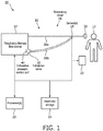
- FIG. 1 schematically illustrates a pressure support system 10 configured to provide pressure support to a subject 12.
- system 10 includes one or more of a respiratory therapy flow device 14, a respiratory circuit 16, an exhalation valve 50, a sensor 18, a processor 20, a user interface 22, electronic storage 24, and/or other components.
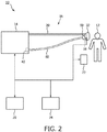
- System 10 is configured to be interchanged between two system configurations: (1) a dual-limb system with two gas carrying conduits (e.g., an inspiratory limb and an expiratory limb); and (2) a single-limb system that includes only the inspiratory limb (shown in FIG. 2 ).
- exhalation valve 50 is disposed on the housing of respiratory therapy flow device 14 and coupled with an exhalation pressure control port 40.
- An expiratory limb 30b of respiratory circuit 16 also couples with valve 50 such that exhaust gas from subject 12 flows to the atmosphere following a path through valve 50.
- Respiratory therapy flow device 14 provides pressurized gas to valve 50 to control gas exhaled by subject 12 through valve 50 to regulate the flow of exhaust gas to the atmosphere.
- valve 50 is removed from the housing of respiratory therapy flow device 14 and a pressure control line 60 connects exhalation pressure control port 40 to valve 50 to regulate the flow of exhaust gas to the atmosphere. This allows pressure provided via exhalation pressure control port 40 to control valve 50 whether valve 50 is located on the respiratory therapy flow device housing (as shown in FIG. 1 ) or at the end of respiratory circuit 16 (shown in FIG. 2 ).
- System 10 is configured such that that when valve 50 is connected to respiratory circuit 16 in a single-limb configuration, valve 50 appears as part of the circuit ( FIG. 2 ), but is easily docked becoming integral to respiratory therapy flow device 14 ( FIG. 1 ).
- Respiratory therapy flow device 14 is configured to generate a pressurized flow of breathable gas for delivery to an airway of subject 12 in accordance with a pressure support therapy regime.
- Respiratory therapy flow device 14 may be and/or include one or more of a pressure generator, a ventilator, a positive airway pressure device (PAP/CPAP/BiPAP®/etc.), and/or other devices.
- Respiratory therapy flow device 14 is configured to provide the pressurized flow of breathable gas for delivery to the airway of subject 12 via respiratory circuit 16.
- Respiratory therapy flow device 14 receives a flow of gas from a gas source, such as the ambient atmosphere, and elevates the pressure of that gas for delivery to subject 12.
- Respiratory therapy flow device 14 includes any device, such as, for example, a pump, blower, piston, or bellows, that is capable of elevating the pressure of the received gas for delivery to subject 12.
- Respiratory therapy flow device 14 may include a motor.
- Respiratory therapy flow device 14 may comprise one or more valves for controlling the flow of gas. The present disclosure also contemplates controlling the operating speed of the blower, either alone or in combination with such valves, to control the gas provided to subject 12.
- Respiratory therapy flow device 14 may be configured to adjust pressure levels, flow, humidity, velocity, acceleration, and/or other parameters of the pressurized flow of breathable gas in substantial synchronization with the breathing phases (e.g., inhalation/exhalation) of subject 12.
- Subject 12 may or may not initiate one or more phases of respiration.
- Respiratory therapy may be implemented as pressure control, pressure support, and/or volume control.
- the pressure of the pressurized flow of breathable gas may be adjusted to an inspiratory pressure.
- the pressure and/or flow of the pressurized flow of breathable gas may be adjusted to an expiratory pressure.
- Other schemes for providing respiratory therapy through the delivery of the pressurized flow of breathable gas are contemplated.
- Respiratory therapy flow device 14 is configured to deliver a control flow of pressurized gas through exhalation pressure control port 40.
- Exhalation pressure control port 40 is a port in respiratory therapy flow device 14 that is separate from the coupling between respiratory circuit 16 and respiratory therapy flow device 14 where respiratory circuit 16 receives the pressurized flow of breathable gas.
- the control flow of gas may be produced by, for example, the pump, blower, piston, or bellows of respiratory therapy flow device 14.
- the control flow of gas may be produced separately from and/or be separated from the pressurized flow of breathable gas by one or more valves for controlling the flow of gas included in respiratory therapy flow device 14.
- the present disclosure also contemplates controlling the motor of the respiratory therapy flow device 14 and the operating speed of the blower, either alone or in combination with such valves, to produce the control flow of pressurized gas provided via exhalation pressure control port 40.
- Respiratory circuit 16 is configured to communicate the pressurized flow of breathable gas to the airway of subject 12.
- respiratory circuit 16 is configured to communicate the pressurized flow of breathable gas from respiratory therapy flow device 14 to the airway of subject 12.
- respiratory circuit 16 comprises one or more of a conduit 30, an interface appliance 32, and/or other components.
- Interface appliance 32 is configured to deliver the flow of gas to the airway of subject 12.
- interface appliance 32 is configured to be non-invasively engaged by the nose and/or mouth of subject 12.
- Non-invasive engagement comprises removably engaging one or more external orifices of the airway of subject 12 (e.g., nostrils and/or mouth) to communicate gas between the airway of subject 12 and interface appliance 32.
- interface appliance 32 is removably coupled to conduit 30. Interface appliance 32 may be removed for cleaning and/or for other purposes.
- non-invasive interface appliance 32 may comprise, for example, a nasal cannula, a nasal mask, a nasal/oral mask, a full face mask, a total face mask, and/or other interface appliances that communicate a flow of gas with an airway of a subject.
- interface appliance 32 is invasive.
- Some examples of invasive interface appliances that may comprise interface appliance 32 are endotracheal tubes, tracheostomy tubes, and or other devices. The present disclosure is not limited to these non-invasive and/or invasive examples, and contemplates delivery of the flow of gas to the subject using any interface appliance.
- Respiratory circuit 16 may further comprise optional valves and/or orifices that serve to regulate an amount of inspiratory pressure, an inspiratory flow rate, an expiratory pressure, an expiratory flow rate, and/or other parameters of the pressurized flow of breathable gas that is delivered to the airway of subject 12.
- the inspiratory pressure, the expiratory pressure, or both may be regulated by valves and/or orifices in interface appliance 32 and/or conduits 30.
- the use of one-way inspiration valves will allow the subject 12 to freely inhale additional ambient air.
- PEEP intrinsic positive end expiratory pressure
- the use of fixed and/or regulated expiratory orifices may provide additional positive expiratory pressure (PEP).
- Respiratory circuit 16 is illustrated in FIG. 1 as a dual-limbed interface for the delivery of the pressurized flow of gas to the airway of the subject.
- respiratory circuit 16 has a first limb 30a configured to provide the pressurized flow of breathable gas to the airway of subject 12, and a second limb 30b configured to selectively exhaust exhaled gases.
- the scope of this disclosure also includes single-limbed circuits.
- the limbs e.g., conduits 30 shown in FIG. 1 and/or FIG. 2
- Conduits 30 are configured to convey the pressurized flow of breathable gas to interface appliance 32.
- Conduits 30 may be a flexible length of hose, and/or other conduits that place interface appliance 32 in fluid communication with other components of system 10 (e.g., respiratory therapy flow device 14).
- Conduits 30 have a sufficient diameter to effectively deliver the pressurized flow of breathable gas with a flow rate and/or pressure that maintains adequate pressure support ventilation.
- respiratory circuit 16 may include a dual lumen type conduit 30 where a small bore lumen is used to sense (e.g., see the descriptions of sensor 18 and processor 20 below) the respiration pattern of subject 12 and control the pressurized flow of breathable gas in synchrony with the spontaneous breathing of the subject.
- valve 50 is coupled to a first end of a pressure control line 60.
- a second end of pressure control line 60 is coupled to respiratory therapy flow device 14 at exhalation pressure control port 40 separately from respiratory circuit 16.
- the second end of pressure control line 60 may be coupled to a pressure source other than respiratory therapy flow device 14.
- Pressure control line 60 may be a flexible length of hose, or other conduit, that places valve 50 in fluid communication with exhalation pressure control port 40.
- Pressure control line 60 is configured to convey a control flow of gas (e.g., air) to valve 50.
- the control flow of gas delivered to pressure control line 60 is separate from the pressurized flow of breathable gas delivered to conduit 30.
- control flow of gas generated by respiratory therapy flow device 14 is controlled by one or more valves within respiratory therapy flow device 14, processor 20, and/or other components of system 10.
- Valve 50 is configured to receive the control flow of gas from respiratory therapy flow device 14 via pressure control line 60.
- Exhalation valve 50 is configured to be removably engaged with exhalation pressure control port 40 and respiratory circuit 16.
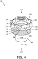
- FIG. 3 - 5 illustrate valve 50.
- valve 50 comprises a lid 52, a diaphragm 54, a housing body 56, and/or other components.
- housing body 56 is configured to house diaphragm 54 and receive lid 52.
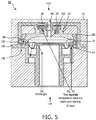
- Lid 52 is retained to housing body 58 in such a way that during engagement to a housing 190 of respiratory therapy flow device 14 (see FIG. 5 ) at exhalation pressure control port 40, for example, compression of diaphragm 54 is primarily axial, with minimal to no torsion, so as to not substantially deform diaphragm 54.
- an engagement between valve 50 and exhalation pressure control port 40 causes lid 52 to form a compression seal 70 with exhalation pressure control port 40, diaphragm 54 to form a compression seal 72 with the lid, and diaphragm 54 to be selectively controlled via gas pressure received through exhalation pressure control port 40 such that gas in respiratory circuit 16 flows 76 to the ambient atmosphere during exhalation by subject 12 (not shown).
- housing body 56 includes a ramped lock 58 configured to engage respiratory therapy flow device 14 (not shown) at exhalation pressure control port 40 (not shown).
- Ramped lock 58 drives valve 50 into exhalation pressure control port 40.
- ramped lock 58 comprises at least one individual ramped lock.
- ramped lock 58 comprises three individual ramped locks spaced approximately equidistant from each other on an outer circumference 80 of housing body 56. This is not intended to be limiting.
- Ramped locks 58 may comprise any number and or type of individual locks positioned in multiple locations on outer circumference 80 as long as system 10 functions as described herein.
- valve 50 causes valve 50 to make the seals described above (e.g., lid 52 with exhalation pressure control port 40 and diaphragm 54 to lid 52, see reference numbers 70 and 72 in FIG. 5 ).
- the three piece assembly design of valve 50 allows for a direct, axial compression of both seals, reducing and/or eliminating twist on diaphragm 54, thus reducing and/or eliminating deformation of diaphragm 54, and allowing for a more consistent performance relative to prior art valves.
- Ramped lock 58 forms a channel 100 in housing body 56 that has a depth that extends from outer circumference 80 toward a central axis 102 of valve 50.
- Channel 100 comprises an alignment portion 104 and a compression locking portion 106.
- Alignment portion 104 is configured to orient ramped lock 58 with respect to corresponding locking features 160 in exhalation pressure control port 40 (shown in FIG. 5 ).
- Alignment portion 104 extends from a first end 112 of housing body 56 toward a second end 114 of housing body 56 substantially parallel to axis 102 on outer circumference 80.
- Alignment portion 104 has an open end 120 at first end 112 of housing body 56 and a closed end 122 toward second end 114.
- Compression locking portion 106 extends from and edge 150 of closed end 122 around housing body 56 on outer circumference 80. As compression locking portion 106 extends from alignment portion 104, compression locking portion 106 declines away from first end 112 of housing body 56. Compression locking portion 106 is configured to rotate 108 with respect to corresponding locking features 160 ( FIG. 5 ) in exhalation pressure control port 40. Corresponding locking features 160 in exhalation pressure control port 40 ride in compression locking portion 106 during rotation and lock on a locking protrusion 110 of compression locking portion 106. Locking protrusion 110 extends into compression locking portion 106 from a first side 130 of compression locking portion 106 toward a second side 132 substantially parallel to axis 102. Locking protrusion is located near an end 134 of compression locking portion 106. In some implementations, valve 50 is configured such that ramped lock 58 of housing body 56 is a cam lock, and/or other locks.
- a user may rotate valve 50 in exhalation pressure control port 40 until alignment portion 104 aligns with corresponding locking features 160 ( FIG. 5 ) in exhalation pressure control port 40.
- the user may push (e.g., causing the compression seals described herein) valve 50 into exhalation pressure control port 40 until corresponding locking features 160 reach and/or nearly reach closed end 122 of alignment portion 104 and then rotate 108 valve 50 such that corresponding locking features 160 of exhalation control port 40 ride in compression locking portion 106 until they lock on locking protrusion 110.
- Ramped lock 58 drives the valve into exhalation pressure control port 40.
- valve 50 maintains the compression seal between the diaphragm 54 and lid 52, and the compression seal lid 52 makes with exhalation pressure control port 40.
- FIG. 5 illustrates a section view of valve 50 in exhalation pressure control port 40.
- Exhalation pressure control port 40 may be formed in a housing 190 of respiratory therapy flow device 14, for example.
- Exhalation pressure control port 40 may include a male connector 192 configured to couple with lid 52 of valve 50, one or more locking features 160 that correspond to ramped lock 58, and/or other components.
- Corresponding locking features may include, for example, a protrusion configured to ride in the channel 104, 106 formed by ramped lock 58 and/or engage locking protrusion 110, and/or other features.
- Exhalation pressure control port 40 may be configured to receive, accept, engage, and/or otherwise couple with pressure control lines for other active circuits when valve 50 is not in use (engaged) with respiratory therapy flow device 14.
- Respiratory therapy flow device 14 may deliver the control flow of gas at a pilot pressure via a proportional valve controlled by processor 20 (not shown in FIG. 5 ) through male connector 192 to control exhalation by subject 12 (not shown in FIG. 5 ).
- the pilot pressure pushes on diaphragm 54 and controls the exhalation pressure necessary to displace diaphragm 54 and allow gas to be exhaled 76 to atmosphere.
- sensor 18 is configured to generate output signals conveying information related to one or more gas parameters of the pressurized flow of breathable gas within system 10.
- the one or more parameters of the gas within system 10 may comprise gas parameters related to the pressurized flow of breathable gas, breathing parameters related to respiration of subject 12, and/or other parameters.
- Sensor 18 may comprise one or more sensors that measure such parameters directly (e.g., through fluid communication with the flow of gas in interface appliance 32 and/or conduit 30).
- Sensor 18 may comprise one or more sensors that generate output signals related to the one or more parameters indirectly.
- sensor 18 may comprise one or more sensors configured to generate an output based on an operating parameter of respiratory therapy flow device 14 (e.g., motor current, voltage, rotational velocity, and/or other operating parameters), and/or other sensors.
- an operating parameter of respiratory therapy flow device 14 e.g., motor current, voltage, rotational velocity, and/or other operating parameters
- the one or more gas parameters of the pressurized flow of breathable gas may comprise, for example, one or more of a flow rate, a volume, a pressure, humidity, temperature, acceleration, velocity, concentration of one or more constituents (e.g., the concentration of oxygen), and/or other gas parameters.
- Breathing parameters related to the respiration of subject 12 may comprise a tidal volume, a timing (e.g., beginning and/or end of inhalation, beginning and/or end of exhalation, etc.), a respiration rate, a duration (e.g., of inhalation, of exhalation, of a single breathing cycle, etc.), respiration frequency, and/or other breathing parameters.
- sensor 18 comprises one or more flow rate sensors configured to generate output signals conveying information related to the flow rate of the pressurized flow of breathable gas.
- Flow rate sensors suitable for use as sensor 18 may include, for example, mechanical flow rate sensors, pressure based flow rate sensors, optical flow rate sensors, thermal mass flow rate sensors, magnetic flow rate sensors, and/or other flow rate sensors.
- sensor 18 comprises one or more pressure sensors configured to generate output signals conveying information related to the pressure of the pressurized flow of breathable gas.
- Pressure sensors suitable for use as sensor 18 may include, for example, mechanical sensors, capacitive sensors, electromagnetic sensors, piezoelectric sensors, optical sensors, dual lumen sensors, and/or other pressure sensors.
- sensor 18 may comprise one or more oxygen sensors configured to generate output signals related to the concentration of oxygen in the pressurized flow of breathable gas delivered to and/or exhaled by subject 12.
- Sensor 18 is illustrated in FIG. 1 at a single location in system 10, this is not intended to be limiting. Sensor 18 may comprise sensors disposed in a plurality of locations, such as for example, at various locations within (or in communication with) conduit 30, within respiratory therapy flow device 14, within (or in communication with) interface appliance 32, and/or other locations.
- Processor 20 is configured to provide information processing capabilities in system 10.
- processor 20 may comprise one or more of a digital processor, an analog processor, a digital circuit designed to process information, an analog circuit designed to process information, a state machine, and/or other mechanisms for electronically processing information.
- processor 20 is shown in FIG. 1 as a single entity, this is for illustrative purposes only.
- processor 20 may comprise a plurality of processing units. These processing units may be physically located within the same device (e.g., respiratory therapy flow device 14), or processor 20 may represent processing functionality of a plurality of devices operating in coordination.
- Processor 20 is configured, by computer readable instructions, to control respiratory therapy flow device 14 and/or other components of system 10 to deliver the pressurized flow of breathable gas to the subject according to a pressure support therapy regime.
- Pressure support therapy may be used to maintain an open airway in subject 12 so that oxygen, carbon dioxide, and/or other gases may be exchanged more easily, requiring little and/or no effort from subject 12.
- Processor 20 may be configured to control the system components based on the output signals from sensor 18 and/or other information.
- processor 20 may control the components of system 10 such that the pressure support provided to subject 12 via the pressurized flow of breathable gas comprises continuous positive airway pressure support (CPAP), bilevel positive airway pressure support (BPAP), proportional positive airway pressure support (PPAP), and/or other types of pressure support therapy.
- CPAP continuous positive airway pressure support
- BPAP bilevel positive airway pressure support
- PPAP proportional positive airway pressure support
- CPAP supplies a fixed positive pressure to maintain a continuous level of positive airway pressure in a patient.
- BPAP provides a first inspiratory pressure (IPAP) and a second, typically lower, expiratory pressure (EPAP) for easier exhalation during ventilation.
- IIPAP first inspiratory pressure
- EPAP expiratory pressure
- system 10 may apply variable pressure support in which the amount of pressure delivered to the patient during inhalation and/or during exhalation is determined and delivered on a breath by breath basis.
- Processor 20 is configured such that controlling respiratory therapy flow device 14 and/or other components of system 10 to deliver the pressurized flow of breathable gas to subject 12 according to a pressure support therapy regime may include determining inhalation phases and/or exhalation phases during breathing of subject 12 based on the output signals and/or other information. Controlling respiratory therapy flow device 14 and/or other components of system 10 may include controlling one or more valves associated with respiratory therapy flow device 14, conduits 30, interface appliance 32, and/or other components of system 10.
- processor 20 is configured to control respiratory therapy flow device 14 to deliver a control flow of pressurized gas through exhalation pressure control port 40.
- the control flow of gas may be controlled separately from the pressurized flow of breathable gas delivered to subject 12.
- processor 20 is configured to control respiratory therapy flow device 14 to deliver the control flow of gas at a pilot pressure via a proportional valve controlled by processor 20 to control exhalation by subject 12. The pilot pressure pushes on diaphragm 54 ( FIG. 3 ) and controls the exhalation pressure necessary to displace diaphragm 54 and allow gas to be exhaled 76 ( FIG. 5 ) to atmosphere.
- User interface 22 is configured to provide an interface between system 10 and subject 12 and/or other users through which subject 12 and/or other users may provide information to and receive information from system 10.
- Other users may comprise, for example, a caregiver, a doctor, and/or other users.
- This enables data, cues, results, and/or instructions and any other communicable items, collectively referred to as "information," to be communicated between a user (e.g., subject 12) and one or more of respiratory therapy flow device 14, processor 20, and/or other components of system 10.
- a user may specify one or more therapy regimes and/or therapy regime set points that are to be delivered to subject 12 using user interface 22.
- therapy pressures, the breath rate of subject 12, and/or other information may be displayed to a user (e.g., subject 12) via user interface 22.
- Examples of interface devices suitable for inclusion in user interface 22 comprise a keypad, buttons, switches, a keyboard, knobs, levers, a display screen, a touch screen, speakers, a microphone, an indicator light, an audible alarm, a printer, a tactile feedback device, and/or other interface devices.
- user interface 22 comprises a plurality of separate interfaces.
- user interface 22 comprises at least one interface that is provided integrally with respiratory therapy flow device 14, and/or processor 20.
- user interface 22 may be integrated with a removable storage interface provided by electronic storage 24.
- information may be loaded into system 10 from removable storage (e.g., a smart card, a flash drive, a removable disk, etc.) that enables the user(s) to customize the implementation of system 10.
- removable storage e.g., a smart card, a flash drive, a removable disk, etc.
- Other exemplary input devices and techniques adapted for use with system 10 as user interface 22 comprise, but are not limited to, an RS-232 port, RF link, an IR link, modem (telephone, cable or other).
- any technique for communicating information with system 10 is contemplated by the present disclosure as user interface 22.
- electronic storage 24 comprises electronic storage media that electronically stores information.
- the electronic storage media of electronic storage 24 may comprise one or both of system storage that is provided integrally (i.e., substantially non-removable) with system 10 and/or removable storage that is removably connectable to system 10 via, for example, a port (e.g., a USB port, a firewire port, etc.) or a drive (e.g., a disk drive, etc.).
- a port e.g., a USB port, a firewire port, etc.
- a drive e.g., a disk drive, etc.
- Electronic storage 24 may comprise one or more of optically readable storage media (e.g., optical disks, etc.), magnetically readable storage media (e.g., magnetic tape, magnetic hard drive, floppy drive, etc.), electrical charge-based storage media (e.g., EPROM, RAM, etc.), solid-state storage media (e.g., flash drive, etc.), and/or other electronically readable storage media.
- Electronic storage 24 may store software algorithms, information determined by processor 20, information received via user interface 22, and/or other information that enables system 10 to function as described herein.
- Electronic storage 24 may be (in whole or in part) a separate component within system 10, or electronic storage 24 may be provided (in whole or in part) integrally with one or more other components of system 10 (e.g., user interface 22, processor 20, etc.).
- Information determined by processor 20 and/or stored by electronic storage 24 may comprise information related to respiration of subject 12, and/or other information.
- the information stored by electronic storage 24 may be viewed via user interface 22, viewed by connecting (wired and/or wireless) to a separate computer, and/or other via other methods.
- the information stored by electronic storage 24 may be used, for example, to adjust therapy settings, used by a doctor to make medical decisions, and/or for other uses.
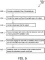
- FIG. 6 illustrates a method 600 for providing pressure support to a subject with a pressure support system.
- the system comprises a respiratory flow device that includes an exhalation pressure control port, a respiratory circuit, and an exhalation valve that includes a lid, a diaphragm, and a housing body.
- the housing body comprises a ramped lock.
- method 600 may be implemented in one or more processing devices (e.g., a digital processor, an analog processor, a digital circuit designed to process information, an analog circuit designed to process information, a state machine, and/or other mechanisms for electronically processing information).
- the one or more processing devices may include one or more devices executing some or all of the operations of method 600 in response to instructions stored electronically on an electronic storage medium.
- the one or more processing devices may include one or more devices configured through hardware, firmware, and/or software to be specifically designed for execution of one or more of the operations of method 600.
- a pressurized flow of breathable gas is generated.
- the pressurized flow of breathable gas is generated in accordance with a pressure support therapy regime.
- operation 602 is performed by a respiratory therapy flow device the same as or similar to respiratory therapy flow device 14 (shown in FIG. 1 and described herein).
- the pressurized flow of breathable gas is conducted to the subject.
- operation 604 is performed by a respiratory circuit the same as or similar to respiratory circuit 16 (shown in FIG. 1 and described herein).
- the respiratory control circuit is a dual-limb active exhalation circuit.
- the respiratory control circuit is a single-limb circuit.
- exhaled gas is conducted away from the subject.
- operation 606 is performed by a respiratory circuit the same as or similar to respiratory circuit 16 (shown in FIG. 1 and described herein).
- a diaphragm is housed with a housing body of the valve.
- a lid of the exhalation valve is received with the housing body of the valve.
- operation 608 is performed by a housing body the same as or similar to housing body 56 (shown in FIG. 3 and described herein).
- the valve is removably engaged with the exhalation pressure control port of the respiratory flow device.
- Removably engaging includes coupling, with the ramped lock, the respiratory therapy flow device at the exhalation pressure control port; causing the lid to form a compression seal around the exhalation pressure control port; and causing the diaphragm to form a compression seal with the lid.
- the ramped lock is a cam lock.
- the ramped lock comprises three individual ramped locks spaced approximately equidistant from each other on an outer circumference of the housing.
- operation 610 is performed by a valve and an exhalation pressure control port the same as similar to valve 56 and exhalation pressure control port 40 (shown in FIG. 1 and described herein).
- the diaphragm is selectively controlled such that gas in the respiratory circuit flows to the ambient atmosphere during exhalation by the subject.
- the diaphragm is selectively controlled via gas pressure received through the exhalation pressure control port.
- operation 612 is performed by an exhalation pressure control port the same as or similar to exhalation pressure control port 40 (shown in FIG. 1 and described herein).
- any reference signs placed between parentheses shall not be construed as limiting the claim.
- the word “comprising” or “including” does not exclude the presence of elements or steps other than those listed in a claim.
- several of these means may be embodied by one and the same item of hardware.
- the word “a” or “an” preceding an element does not exclude the presence of a plurality of such elements.
- any device claim enumerating several means several of these means may be embodied by one and the same item of hardware.
- the mere fact that certain elements are recited in mutually different dependent claims does not indicate that these elements cannot be used in combination.
Landscapes
- Health & Medical Sciences (AREA)
- Engineering & Computer Science (AREA)
- Pulmonology (AREA)
- Heart & Thoracic Surgery (AREA)
- Life Sciences & Earth Sciences (AREA)
- Veterinary Medicine (AREA)
- Emergency Medicine (AREA)
- Public Health (AREA)
- Anesthesiology (AREA)
- Biomedical Technology (AREA)
- General Health & Medical Sciences (AREA)
- Hematology (AREA)
- Animal Behavior & Ethology (AREA)
- General Engineering & Computer Science (AREA)
- Mechanical Engineering (AREA)
- Physics & Mathematics (AREA)
- Fluid Mechanics (AREA)
- Otolaryngology (AREA)
- Measurement Of The Respiration, Hearing Ability, Form, And Blood Characteristics Of Living Organisms (AREA)
- Percussion Or Vibration Massage (AREA)
Claims (5)
- Druckunterstützungssystem (10), ausgebildet, um Druckunterstützung für ein Subjekt bereitzustellen, wobei das System umfasst:eine Strömungsvorrichtung für Atemtherapie (14), die ausgebildet ist, um eine druckbeaufschlagte Strömung von Atemgas zur Abgabe an einen Luftweg des Subjekts gemäß eines Therapieschemas zur Druckunterstützung zu erzeugen, wobei die Strömungsvorrichtung für Atemtherapie einen Anschluss zur Steuerung des Ausatmungsdrucks (40) enthält;einen Atemkreislauf (16), der ausgebildet ist, um die druckbeaufschlagte Strömung von Atemgas an das Subjekt zu leiten, und um ausgeatmetes Gas vom Subjekt zu leiten; undein Ausatmungsventil (50), das ausgebildet ist, damit der Anschluss zur Steuerung des Ausatmungsdrucks und der Atemkreislauf abnehmbar darin eingreifen, wobei das Ventil einen Deckel (52), eine Membrane (54) und einen Gehäusekörper (56) umfasst, wobei der Gehäusekörper ausgebildet ist, um die Membrane unterzubringen und den Deckel aufzunehmen, wobei der Gehäusekörper eine Verriegelung (58) umfasst, die ausgebildet ist, um in die Strömungsvorrichtung für Atemtherapie am Anschluss zur Steuerung des Ausatmungsdrucks so einzugreifen, dass ein Eingreifen zwischen dem Ventil und dem Anschluss zur Steuerung des Ausatmungsdrucks verursacht, dass der Deckel eine Pressdichtung mit dem Anschluss zur Steuerung des Ausatmungsdrucks bildet, die Membrane eine Pressdichtung mit dem Deckel bildet und die Membrane selektiv über den durch den Anschluss zur Steuerung des Ausatmungsdrucks empfangenen Gasdruck so gesteuert wird, dass während des Ausatmens durch das Subjekt Gas im Atemkreislauf in die umgebende Atmosphäre strömt.
- System nach Anspruch 1, wobei der Atemkreislauf ein zweigliedriger aktiver Ausatmungskreislauf ist.
- System nach Anspruch 1, weiter umfassend eine Drucksteuerungsleitung (60), die ausgebildet ist, um Gas vom Anschluss zur Steuerung des Ausatmungsdrucks zum Deckel zu leiten, wobei als Reaktion darauf, dass das Ventil vom Anschluss zur Steuerung des Ausatmungsdrucks getrennt wird, die Membrane selektiv über vom Anschluss zur Steuerung des Ausatmungsdrucks durch die Drucksteuerungsleitung empfangenen Gasdruck gesteuert wird, um es zuzulassen, dass ausgeatmetes Gas im Atemkreislauf in die umgebende Atmosphäre strömt.
- System nach Anspruch 1, wobei das Ventil so ausgebildet ist, dass die Verriegelung eine rampenförmige Verriegelung ist.
- System nach Anspruch 4, wobei die rampenförmige Verriegelung drei individuelle rampenförmige Verriegelungen umfasst, die ungefähr im gleichen Abstand voneinander an einem Außenumfang des Gehäusekörpers beabstandet sind.
Applications Claiming Priority (2)
| Application Number | Priority Date | Filing Date | Title |
|---|---|---|---|
| US201461951045P | 2014-03-11 | 2014-03-11 | |
| PCT/IB2015/051531 WO2015136407A1 (en) | 2014-03-11 | 2015-03-03 | Compact dual limb diaphragm valve system and method cross-reference to related applications |
Publications (2)
| Publication Number | Publication Date |
|---|---|
| EP3116578A1 EP3116578A1 (de) | 2017-01-18 |
| EP3116578B1 true EP3116578B1 (de) | 2019-05-08 |
Family
ID=52693008
Family Applications (1)
| Application Number | Title | Priority Date | Filing Date |
|---|---|---|---|
| EP15710924.0A Active EP3116578B1 (de) | 2014-03-11 | 2015-03-03 | Kompaktes zweigliedriges membranventilsystem |
Country Status (5)
| Country | Link |
|---|---|
| US (1) | US11147939B2 (de) |
| EP (1) | EP3116578B1 (de) |
| JP (1) | JP2017506964A (de) |
| CN (1) | CN106102813B (de) |
| WO (1) | WO2015136407A1 (de) |
Families Citing this family (4)
| Publication number | Priority date | Publication date | Assignee | Title |
|---|---|---|---|---|
| CN106102813B (zh) | 2014-03-11 | 2019-03-12 | 皇家飞利浦有限公司 | 紧凑的双肢隔膜阀系统和方法 |
| DE102016220812A1 (de) * | 2016-10-24 | 2018-04-26 | Hamilton Medical Ag | Exspirationsventil für eine Beatmungsvorrichtung mit geräuschemissionsreduzierter Ventilgestaltung |
| CN110603069B (zh) * | 2017-02-21 | 2023-08-29 | 菲舍尔和佩克尔保健有限公司 | 用于呼吸治疗系统的流体捕集器 |
| WO2020109030A1 (en) | 2018-11-27 | 2020-06-04 | Koninklijke Philips N.V. | Modular exhalation device that transitions circuits between active and non-invasive ventilation modes |
Family Cites Families (17)
| Publication number | Priority date | Publication date | Assignee | Title |
|---|---|---|---|---|
| US3610236A (en) * | 1966-11-22 | 1971-10-05 | Globe Safety Products Inc | Resuscitator device |
| US3633605A (en) * | 1969-03-18 | 1972-01-11 | Robertshaw Controls Co | Pneumatic control system and pneumatic control device therefor or the like |
| US4241756A (en) | 1978-11-29 | 1980-12-30 | C. R. Bard, Inc. | Exhalation valve assembly |
| CA1234736A (en) * | 1983-11-25 | 1988-04-05 | The Boc Group, Inc. | Exhalation valve |
| CA1286942C (en) | 1987-07-31 | 1991-07-30 | Keith Gilman | Exhalation valve assembly |
| US5020532A (en) | 1988-11-14 | 1991-06-04 | Baxter International Inc. | Exhalation valve for respiratory circuit |
| US5484270A (en) * | 1994-02-28 | 1996-01-16 | Carmeli Adahan | Pump particularly useful in respirator apparatus and exhalation valve assembly therefor |
| US5937855A (en) | 1995-04-21 | 1999-08-17 | Respironics, Inc. | Flow regulating valve in a breathing gas delivery system |
| US6283122B1 (en) | 1999-03-10 | 2001-09-04 | Flight Medical Ltd. | Exhalation valve for respirator |
| FR2812203B1 (fr) * | 2000-07-31 | 2003-01-03 | Saime Sarl | Appareil d'aide a la ventilation d'un patient |
| DE102004049151B3 (de) * | 2004-10-07 | 2005-08-25 | Dräger Medical AG & Co. KGaA | Membranventil für ein Beatmungsgerät |
| WO2009089807A1 (de) * | 2008-01-15 | 2009-07-23 | Weinmann Geräte für Medizin GmbH + Co. KG | Geräuscharmes anwendungsinterface mit integriertem peep-ventil |
| EP3865171A1 (de) * | 2010-03-25 | 2021-08-18 | ResMed Paris SAS | Vorrichtung zur steuerung des atemgaseinlasses einer vorrichtung zur behandlung von atemwegserkrankungen |
| JP5872554B2 (ja) * | 2010-08-13 | 2016-03-01 | コーニンクレッカ フィリップス エヌ ヴェKoninklijke Philips N.V. | 確率的変動を用いて被験者の気道に呼吸可能なガスの加圧流を供給するシステム及び方法 |
| GB2487089A (en) * | 2011-01-10 | 2012-07-11 | Intersurgical Ag | Diaphragm valve assembly with control chamber and lid |
| EP2854902B1 (de) * | 2012-05-25 | 2017-01-11 | Aptar France SAS | Autoinjektor |
| CN106102813B (zh) | 2014-03-11 | 2019-03-12 | 皇家飞利浦有限公司 | 紧凑的双肢隔膜阀系统和方法 |
-
2015
- 2015-03-03 CN CN201580012716.6A patent/CN106102813B/zh active Active
- 2015-03-03 JP JP2016555279A patent/JP2017506964A/ja active Pending
- 2015-03-03 WO PCT/IB2015/051531 patent/WO2015136407A1/en active Application Filing
- 2015-03-03 US US15/124,361 patent/US11147939B2/en active Active
- 2015-03-03 EP EP15710924.0A patent/EP3116578B1/de active Active
Non-Patent Citations (1)
| Title |
|---|
| None * |
Also Published As
| Publication number | Publication date |
|---|---|
| JP2017506964A (ja) | 2017-03-16 |
| EP3116578A1 (de) | 2017-01-18 |
| WO2015136407A1 (en) | 2015-09-17 |
| US11147939B2 (en) | 2021-10-19 |
| US20170014594A1 (en) | 2017-01-19 |
| CN106102813A (zh) | 2016-11-09 |
| CN106102813B (zh) | 2019-03-12 |
Similar Documents
| Publication | Publication Date | Title |
|---|---|---|
| US9987444B2 (en) | System and method for limited flow respiratory therapy | |
| JP6223340B2 (ja) | 人工呼吸療法装置を制御するための方法及び機器 | |
| EP2827930B1 (de) | System zur steuerung des insufflationsdrucks während der inexsufflation | |
| US10335564B2 (en) | System and method for controlling exsufflation pressure during in-exsufflation | |
| US9642976B2 (en) | Systems and methods for intra-pulmonary percussive ventilation integrated in a ventilator | |
| WO2016079703A1 (en) | Non-invasive ventilation with high frequency oscillations | |
| EP3116578B1 (de) | Kompaktes zweigliedriges membranventilsystem | |
| EP3209357B1 (de) | System zur steuerung von leckagen | |
| US10646684B2 (en) | Reversible component for multiple respiratory support modes | |
| US11471638B2 (en) | Pressure support system valve | |
| US20140326242A1 (en) | Sysems and methods for using partial co2 rebreathing integrated in a ventilator and measurements thereof to determine noninvasive cardiac output | |
| EP3291868B1 (de) | Systeme für verbesserte hustensegmentierung | |
| US11052207B2 (en) | Gas sensing apparatus | |
| US10881821B2 (en) | Mechanical ventilation based on alveolar ventilation |
Legal Events
| Date | Code | Title | Description |
|---|---|---|---|
| STAA | Information on the status of an ep patent application or granted ep patent |
Free format text: STATUS: THE INTERNATIONAL PUBLICATION HAS BEEN MADE |
|
| PUAI | Public reference made under article 153(3) epc to a published international application that has entered the european phase |
Free format text: ORIGINAL CODE: 0009012 |
|
| STAA | Information on the status of an ep patent application or granted ep patent |
Free format text: STATUS: REQUEST FOR EXAMINATION WAS MADE |
|
| 17P | Request for examination filed |
Effective date: 20161011 |
|
| AK | Designated contracting states |
Kind code of ref document: A1 Designated state(s): AL AT BE BG CH CY CZ DE DK EE ES FI FR GB GR HR HU IE IS IT LI LT LU LV MC MK MT NL NO PL PT RO RS SE SI SK SM TR |
|
| AX | Request for extension of the european patent |
Extension state: BA ME |
|
| DAV | Request for validation of the european patent (deleted) | ||
| DAX | Request for extension of the european patent (deleted) | ||
| REG | Reference to a national code |
Ref country code: DE Ref legal event code: R079 Ref document number: 602015029779 Country of ref document: DE Free format text: PREVIOUS MAIN CLASS: A61M0016200000 Ipc: A61M0016000000 |
|
| RIC1 | Information provided on ipc code assigned before grant |
Ipc: A61M 16/20 20060101ALI20181008BHEP Ipc: F16K 7/17 20060101ALI20181008BHEP Ipc: A61M 16/06 20060101ALI20181008BHEP Ipc: A61M 16/04 20060101ALI20181008BHEP Ipc: A61M 16/00 20060101AFI20181008BHEP Ipc: A61M 16/10 20060101ALI20181008BHEP |
|
| GRAP | Despatch of communication of intention to grant a patent |
Free format text: ORIGINAL CODE: EPIDOSNIGR1 |
|
| STAA | Information on the status of an ep patent application or granted ep patent |
Free format text: STATUS: GRANT OF PATENT IS INTENDED |
|
| INTG | Intention to grant announced |
Effective date: 20181116 |
|
| RIN1 | Information on inventor provided before grant (corrected) |
Inventor name: COLE, KENNETH E. |
|
| GRAS | Grant fee paid |
Free format text: ORIGINAL CODE: EPIDOSNIGR3 |
|
| GRAA | (expected) grant |
Free format text: ORIGINAL CODE: 0009210 |
|
| STAA | Information on the status of an ep patent application or granted ep patent |
Free format text: STATUS: THE PATENT HAS BEEN GRANTED |
|
| AK | Designated contracting states |
Kind code of ref document: B1 Designated state(s): AL AT BE BG CH CY CZ DE DK EE ES FI FR GB GR HR HU IE IS IT LI LT LU LV MC MK MT NL NO PL PT RO RS SE SI SK SM TR |
|
| REG | Reference to a national code |
Ref country code: GB Ref legal event code: FG4D |
|
| REG | Reference to a national code |
Ref country code: CH Ref legal event code: EP Ref country code: AT Ref legal event code: REF Ref document number: 1129215 Country of ref document: AT Kind code of ref document: T Effective date: 20190515 |
|
| REG | Reference to a national code |
Ref country code: DE Ref legal event code: R096 Ref document number: 602015029779 Country of ref document: DE Ref country code: IE Ref legal event code: FG4D |
|
| REG | Reference to a national code |
Ref country code: NL Ref legal event code: MP Effective date: 20190508 |
|
| REG | Reference to a national code |
Ref country code: LT Ref legal event code: MG4D |
|
| PG25 | Lapsed in a contracting state [announced via postgrant information from national office to epo] |
Ref country code: HR Free format text: LAPSE BECAUSE OF FAILURE TO SUBMIT A TRANSLATION OF THE DESCRIPTION OR TO PAY THE FEE WITHIN THE PRESCRIBED TIME-LIMIT Effective date: 20190508 Ref country code: NL Free format text: LAPSE BECAUSE OF FAILURE TO SUBMIT A TRANSLATION OF THE DESCRIPTION OR TO PAY THE FEE WITHIN THE PRESCRIBED TIME-LIMIT Effective date: 20190508 Ref country code: FI Free format text: LAPSE BECAUSE OF FAILURE TO SUBMIT A TRANSLATION OF THE DESCRIPTION OR TO PAY THE FEE WITHIN THE PRESCRIBED TIME-LIMIT Effective date: 20190508 Ref country code: LT Free format text: LAPSE BECAUSE OF FAILURE TO SUBMIT A TRANSLATION OF THE DESCRIPTION OR TO PAY THE FEE WITHIN THE PRESCRIBED TIME-LIMIT Effective date: 20190508 Ref country code: PT Free format text: LAPSE BECAUSE OF FAILURE TO SUBMIT A TRANSLATION OF THE DESCRIPTION OR TO PAY THE FEE WITHIN THE PRESCRIBED TIME-LIMIT Effective date: 20190908 Ref country code: SE Free format text: LAPSE BECAUSE OF FAILURE TO SUBMIT A TRANSLATION OF THE DESCRIPTION OR TO PAY THE FEE WITHIN THE PRESCRIBED TIME-LIMIT Effective date: 20190508 Ref country code: NO Free format text: LAPSE BECAUSE OF FAILURE TO SUBMIT A TRANSLATION OF THE DESCRIPTION OR TO PAY THE FEE WITHIN THE PRESCRIBED TIME-LIMIT Effective date: 20190808 Ref country code: AL Free format text: LAPSE BECAUSE OF FAILURE TO SUBMIT A TRANSLATION OF THE DESCRIPTION OR TO PAY THE FEE WITHIN THE PRESCRIBED TIME-LIMIT Effective date: 20190508 Ref country code: ES Free format text: LAPSE BECAUSE OF FAILURE TO SUBMIT A TRANSLATION OF THE DESCRIPTION OR TO PAY THE FEE WITHIN THE PRESCRIBED TIME-LIMIT Effective date: 20190508 |
|
| PG25 | Lapsed in a contracting state [announced via postgrant information from national office to epo] |
Ref country code: GR Free format text: LAPSE BECAUSE OF FAILURE TO SUBMIT A TRANSLATION OF THE DESCRIPTION OR TO PAY THE FEE WITHIN THE PRESCRIBED TIME-LIMIT Effective date: 20190809 Ref country code: BG Free format text: LAPSE BECAUSE OF FAILURE TO SUBMIT A TRANSLATION OF THE DESCRIPTION OR TO PAY THE FEE WITHIN THE PRESCRIBED TIME-LIMIT Effective date: 20190808 Ref country code: RS Free format text: LAPSE BECAUSE OF FAILURE TO SUBMIT A TRANSLATION OF THE DESCRIPTION OR TO PAY THE FEE WITHIN THE PRESCRIBED TIME-LIMIT Effective date: 20190508 Ref country code: LV Free format text: LAPSE BECAUSE OF FAILURE TO SUBMIT A TRANSLATION OF THE DESCRIPTION OR TO PAY THE FEE WITHIN THE PRESCRIBED TIME-LIMIT Effective date: 20190508 |
|
| REG | Reference to a national code |
Ref country code: AT Ref legal event code: MK05 Ref document number: 1129215 Country of ref document: AT Kind code of ref document: T Effective date: 20190508 |
|
| PG25 | Lapsed in a contracting state [announced via postgrant information from national office to epo] |
Ref country code: EE Free format text: LAPSE BECAUSE OF FAILURE TO SUBMIT A TRANSLATION OF THE DESCRIPTION OR TO PAY THE FEE WITHIN THE PRESCRIBED TIME-LIMIT Effective date: 20190508 Ref country code: AT Free format text: LAPSE BECAUSE OF FAILURE TO SUBMIT A TRANSLATION OF THE DESCRIPTION OR TO PAY THE FEE WITHIN THE PRESCRIBED TIME-LIMIT Effective date: 20190508 Ref country code: DK Free format text: LAPSE BECAUSE OF FAILURE TO SUBMIT A TRANSLATION OF THE DESCRIPTION OR TO PAY THE FEE WITHIN THE PRESCRIBED TIME-LIMIT Effective date: 20190508 Ref country code: SK Free format text: LAPSE BECAUSE OF FAILURE TO SUBMIT A TRANSLATION OF THE DESCRIPTION OR TO PAY THE FEE WITHIN THE PRESCRIBED TIME-LIMIT Effective date: 20190508 Ref country code: RO Free format text: LAPSE BECAUSE OF FAILURE TO SUBMIT A TRANSLATION OF THE DESCRIPTION OR TO PAY THE FEE WITHIN THE PRESCRIBED TIME-LIMIT Effective date: 20190508 Ref country code: CZ Free format text: LAPSE BECAUSE OF FAILURE TO SUBMIT A TRANSLATION OF THE DESCRIPTION OR TO PAY THE FEE WITHIN THE PRESCRIBED TIME-LIMIT Effective date: 20190508 |
|
| REG | Reference to a national code |
Ref country code: DE Ref legal event code: R097 Ref document number: 602015029779 Country of ref document: DE |
|
| PG25 | Lapsed in a contracting state [announced via postgrant information from national office to epo] |
Ref country code: SM Free format text: LAPSE BECAUSE OF FAILURE TO SUBMIT A TRANSLATION OF THE DESCRIPTION OR TO PAY THE FEE WITHIN THE PRESCRIBED TIME-LIMIT Effective date: 20190508 Ref country code: IT Free format text: LAPSE BECAUSE OF FAILURE TO SUBMIT A TRANSLATION OF THE DESCRIPTION OR TO PAY THE FEE WITHIN THE PRESCRIBED TIME-LIMIT Effective date: 20190508 |
|
| PLBE | No opposition filed within time limit |
Free format text: ORIGINAL CODE: 0009261 |
|
| STAA | Information on the status of an ep patent application or granted ep patent |
Free format text: STATUS: NO OPPOSITION FILED WITHIN TIME LIMIT |
|
| RAP2 | Party data changed (patent owner data changed or rights of a patent transferred) |
Owner name: KONINKLIJKE PHILIPS N.V. |
|
| PG25 | Lapsed in a contracting state [announced via postgrant information from national office to epo] |
Ref country code: TR Free format text: LAPSE BECAUSE OF FAILURE TO SUBMIT A TRANSLATION OF THE DESCRIPTION OR TO PAY THE FEE WITHIN THE PRESCRIBED TIME-LIMIT Effective date: 20190508 |
|
| 26N | No opposition filed |
Effective date: 20200211 |
|
| PG25 | Lapsed in a contracting state [announced via postgrant information from national office to epo] |
Ref country code: PL Free format text: LAPSE BECAUSE OF FAILURE TO SUBMIT A TRANSLATION OF THE DESCRIPTION OR TO PAY THE FEE WITHIN THE PRESCRIBED TIME-LIMIT Effective date: 20190508 |
|
| PG25 | Lapsed in a contracting state [announced via postgrant information from national office to epo] |
Ref country code: SI Free format text: LAPSE BECAUSE OF FAILURE TO SUBMIT A TRANSLATION OF THE DESCRIPTION OR TO PAY THE FEE WITHIN THE PRESCRIBED TIME-LIMIT Effective date: 20190508 |
|
| PG25 | Lapsed in a contracting state [announced via postgrant information from national office to epo] |
Ref country code: MC Free format text: LAPSE BECAUSE OF FAILURE TO SUBMIT A TRANSLATION OF THE DESCRIPTION OR TO PAY THE FEE WITHIN THE PRESCRIBED TIME-LIMIT Effective date: 20190508 |
|
| REG | Reference to a national code |
Ref country code: CH Ref legal event code: PL |
|
| REG | Reference to a national code |
Ref country code: BE Ref legal event code: MM Effective date: 20200331 |
|
| PG25 | Lapsed in a contracting state [announced via postgrant information from national office to epo] |
Ref country code: LU Free format text: LAPSE BECAUSE OF NON-PAYMENT OF DUE FEES Effective date: 20200303 |
|
| PG25 | Lapsed in a contracting state [announced via postgrant information from national office to epo] |
Ref country code: CH Free format text: LAPSE BECAUSE OF NON-PAYMENT OF DUE FEES Effective date: 20200331 Ref country code: LI Free format text: LAPSE BECAUSE OF NON-PAYMENT OF DUE FEES Effective date: 20200331 Ref country code: IE Free format text: LAPSE BECAUSE OF NON-PAYMENT OF DUE FEES Effective date: 20200303 |
|
| PG25 | Lapsed in a contracting state [announced via postgrant information from national office to epo] |
Ref country code: BE Free format text: LAPSE BECAUSE OF NON-PAYMENT OF DUE FEES Effective date: 20200331 |
|
| GBPC | Gb: european patent ceased through non-payment of renewal fee |
Effective date: 20200303 |
|
| PG25 | Lapsed in a contracting state [announced via postgrant information from national office to epo] |
Ref country code: GB Free format text: LAPSE BECAUSE OF NON-PAYMENT OF DUE FEES Effective date: 20200303 |
|
| PG25 | Lapsed in a contracting state [announced via postgrant information from national office to epo] |
Ref country code: MT Free format text: LAPSE BECAUSE OF FAILURE TO SUBMIT A TRANSLATION OF THE DESCRIPTION OR TO PAY THE FEE WITHIN THE PRESCRIBED TIME-LIMIT Effective date: 20190508 Ref country code: CY Free format text: LAPSE BECAUSE OF FAILURE TO SUBMIT A TRANSLATION OF THE DESCRIPTION OR TO PAY THE FEE WITHIN THE PRESCRIBED TIME-LIMIT Effective date: 20190508 |
|
| PG25 | Lapsed in a contracting state [announced via postgrant information from national office to epo] |
Ref country code: MK Free format text: LAPSE BECAUSE OF FAILURE TO SUBMIT A TRANSLATION OF THE DESCRIPTION OR TO PAY THE FEE WITHIN THE PRESCRIBED TIME-LIMIT Effective date: 20190508 Ref country code: IS Free format text: LAPSE BECAUSE OF FAILURE TO SUBMIT A TRANSLATION OF THE DESCRIPTION OR TO PAY THE FEE WITHIN THE PRESCRIBED TIME-LIMIT Effective date: 20190908 |
|
| PGFP | Annual fee paid to national office [announced via postgrant information from national office to epo] |
Ref country code: FR Payment date: 20230323 Year of fee payment: 9 |
|
| PGFP | Annual fee paid to national office [announced via postgrant information from national office to epo] |
Ref country code: DE Payment date: 20240328 Year of fee payment: 10 |