EP3116241A2 - Crowd-sourced audio data for venue equalization - Google Patents
Crowd-sourced audio data for venue equalization Download PDFInfo
- Publication number
- EP3116241A2 EP3116241A2 EP16171861.4A EP16171861A EP3116241A2 EP 3116241 A2 EP3116241 A2 EP 3116241A2 EP 16171861 A EP16171861 A EP 16171861A EP 3116241 A2 EP3116241 A2 EP 3116241A2
- Authority
- EP
- European Patent Office
- Prior art keywords
- zone
- audio
- captured
- audio data
- captured audio
- Prior art date
- Legal status (The legal status is an assumption and is not a legal conclusion. Google has not performed a legal analysis and makes no representation as to the accuracy of the status listed.)
- Granted
Links
Images


Classifications
-
- H—ELECTRICITY
- H04—ELECTRIC COMMUNICATION TECHNIQUE
- H04R—LOUDSPEAKERS, MICROPHONES, GRAMOPHONE PICK-UPS OR LIKE ACOUSTIC ELECTROMECHANICAL TRANSDUCERS; ELECTRIC HEARING AIDS; PUBLIC ADDRESS SYSTEMS
- H04R3/00—Circuits for transducers
- H04R3/12—Circuits for transducers for distributing signals to two or more loudspeakers
-
- H—ELECTRICITY
- H04—ELECTRIC COMMUNICATION TECHNIQUE
- H04S—STEREOPHONIC SYSTEMS
- H04S7/00—Indicating arrangements; Control arrangements, e.g. balance control
- H04S7/30—Control circuits for electronic adaptation of the sound field
- H04S7/301—Automatic calibration of stereophonic sound system, e.g. with test microphone
-
- H—ELECTRICITY
- H04—ELECTRIC COMMUNICATION TECHNIQUE
- H04R—LOUDSPEAKERS, MICROPHONES, GRAMOPHONE PICK-UPS OR LIKE ACOUSTIC ELECTROMECHANICAL TRANSDUCERS; ELECTRIC HEARING AIDS; PUBLIC ADDRESS SYSTEMS
- H04R29/00—Monitoring arrangements; Testing arrangements
- H04R29/007—Monitoring arrangements; Testing arrangements for public address systems
-
- H—ELECTRICITY
- H04—ELECTRIC COMMUNICATION TECHNIQUE
- H04S—STEREOPHONIC SYSTEMS
- H04S7/00—Indicating arrangements; Control arrangements, e.g. balance control
- H04S7/30—Control circuits for electronic adaptation of the sound field
- H04S7/307—Frequency adjustment, e.g. tone control
-
- H—ELECTRICITY
- H04—ELECTRIC COMMUNICATION TECHNIQUE
- H04R—LOUDSPEAKERS, MICROPHONES, GRAMOPHONE PICK-UPS OR LIKE ACOUSTIC ELECTROMECHANICAL TRANSDUCERS; ELECTRIC HEARING AIDS; PUBLIC ADDRESS SYSTEMS
- H04R2227/00—Details of public address [PA] systems covered by H04R27/00 but not provided for in any of its subgroups
- H04R2227/007—Electronic adaptation of audio signals to reverberation of the listening space for PA
-
- H—ELECTRICITY
- H04—ELECTRIC COMMUNICATION TECHNIQUE
- H04R—LOUDSPEAKERS, MICROPHONES, GRAMOPHONE PICK-UPS OR LIKE ACOUSTIC ELECTROMECHANICAL TRANSDUCERS; ELECTRIC HEARING AIDS; PUBLIC ADDRESS SYSTEMS
- H04R2430/00—Signal processing covered by H04R, not provided for in its groups
-
- H—ELECTRICITY
- H04—ELECTRIC COMMUNICATION TECHNIQUE
- H04R—LOUDSPEAKERS, MICROPHONES, GRAMOPHONE PICK-UPS OR LIKE ACOUSTIC ELECTROMECHANICAL TRANSDUCERS; ELECTRIC HEARING AIDS; PUBLIC ADDRESS SYSTEMS
- H04R2499/00—Aspects covered by H04R or H04S not otherwise provided for in their subgroups
- H04R2499/10—General applications
- H04R2499/11—Transducers incorporated or for use in hand-held devices, e.g. mobile phones, PDA's, camera's
-
- H—ELECTRICITY
- H04—ELECTRIC COMMUNICATION TECHNIQUE
- H04R—LOUDSPEAKERS, MICROPHONES, GRAMOPHONE PICK-UPS OR LIKE ACOUSTIC ELECTROMECHANICAL TRANSDUCERS; ELECTRIC HEARING AIDS; PUBLIC ADDRESS SYSTEMS
- H04R3/00—Circuits for transducers
- H04R3/005—Circuits for transducers for combining the signals of two or more microphones
Definitions
- aspects disclosed herein generally relate to collection of crowd-sourced equalization data for use in determining venue equalization settings.
- Environmental speaker interactions may cause a frequency response of the speaker to change.
- the speaker outputs may constructively add or subtract at different locations, causing comb filtering or other irregularities.
- speaker outputs may suffer changed frequency response due to room interactions such as room coupling, reflections, and echoing. These effects may differ by venue and even by location within the venue.
- Sound equalization refers to a technique by which amplitude of audio signals at particular frequencies is increased or attenuated. Sound engineers utilize equipment to perform sound equalization to correct for frequency response effects caused by speaker placement. To perform these corrections, the sound engineers may characterize the venue environment using specialized and expensive professional-audio microphones, and make equalization adjustments to the speakers to correct for the detected frequency response irregularities.
- an apparatus in a first illustrative embodiment, includes an audio filtering device configured to receive captured audio signals from a plurality of mobile devices located within a zone of a venue, the captured audio signals determined by audio capture devices of the respective mobile devices in response to receipt of test audio generated by speakers of the venue reproducing a test signal; combine the captured audio signals into zone audio data; and transmit the zone audio data to a sound processor configured to determine equalization settings for the zone based on the captured audio signals and the test signal.
- a system in a second illustrative embodiment, includes a mobile device configured to identify a zone designation indicative of a zone of a venue in which the mobile device is located; capture audio signals indicative of test audio received by an audio capture device of the mobile device; and send the captured audio and the zone designation to a sound processor to determine equalization settings for speakers of the zone of the venue.
- a non-transitory computer-readable medium is encoded with computer executable instructions, the computer executable instructions executable by a processor, the computer-readable medium comprising instructions configured to receive captured audio signals from a plurality of mobile devices located within a zone of a venue, the captured audio signals determined by audio capture devices of the respective mobile devices in response to receipt of test audio generated by speakers of the venue reproducing a test signal; compare each of the captured audio signals with the test signal to determine an associated match indication of each of the captured audio signals; combine the captured audio signals into zone audio data in accordance with the associated match indications; determine a usability score indicative of a number of captured audio signals combined into the zone audio data; and associate the zone audio data with the usability score; and transmit the zone audio data to a sound processor configured to determine equalization settings for the zone based on the captured audio signals and the test signal.
- a sound processor may include a test audio generator configured to provide a test signal, such as white noise, pink noise, a frequency sweep, a continuous noise signal, or some other audio signal.
- the test signal may be provided to one or more speakers of a venue to produce audio output.
- This audio output may be captured by one or more microphones at various points in the venue.
- the captured audio data may be returned to the sound processor via wired or wireless techniques, and analyzed to assist in the equalization of the speakers of the venue.
- the sound processor system may accordingly determine equalization settings to be applied to audio signals before they are applied to the speakers of the venue.
- the sound processor may detect frequencies that should be increased or decreased in amplitude in relation to the overall audio signal, as well as amounts of the increases or decreases.
- multiple capture points, or zones may be provided as input for the sound processor to analyze for proper equalization.
- such systems typically require the use of relatively high-quality and expensive professional-audio microphones.
- An improved equalization system may utilize crowd-sourcing techniques to capture the audio output, instead of or in addition to the use of professional-audio microphones.
- the system may be configured to receive audio data captured from a plurality of mobile devices having microphones, such as smartphones, tablets, wearable devices, and the like.
- the mobile devices may be assigned to zones of the venue, e.g., according to manual user input, triangulation or other location-based techniques.
- enhanced filtering logic may be used to determine a subset of the mobile devices deemed to be providing useful data.
- These useful signals may be combined to form zone audio for the zone of the venue, and may be passed to the sound processor for analysis.
- one or more of the professional-audio microphones may be replaced or augmented by a plurality of mobile devices having audio capture capabilities, without a loss in capture detail and equalization quality.
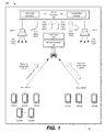
- FIG. 1 illustrates an example system 100 including a sound processor 110 receiving captured audio data 120 from a plurality of mobile devices 118, in accordance to one embodiment.
- the system 100 includes a test audio generator 112 configured to provide test signals 114 to speakers 102 of the venue 104.
- the speakers may generate test audio 116 in the venue 104, which may be captured as captured audio data 120 by the mobile devices 118.
- the mobile devices 118 may transmit the captured audio data 120 to a wireless receiver 122, which may communicate the captured audio data 120 to filtering logic 124.
- the filtering logic 124 may, in turn, provide a zone audio data 126 compiled from a useful subset of the captured audio data 120 to the sound processor 110 to use in the computation of equalization settings 106 for the speakers 102.
- the illustrated system 100 is merely an example, and more, fewer, and/or differently located elements may be used.
- the speakers 102 may be any of various types of devices configured to convert electrical signals into audible sound waves.
- the speakers 102 may include dynamic loudspeakers having a coil operating within a magnetic field and connected to a diaphragm, such that application of the electrical signals to the coil causes the coil to move through induction and power the diaphragm.
- the speakers 102 may include other types of drivers, such as piezoelectric, electrostatic, ribbon or planar elements.
- the venue 104 may include various types of locations having speakers 102 configured to provide audible sound waves to listeners.
- the venue may be a room or other enclosed area such as a concert hall, stadium, restaurant, auditorium, or vehicle cabin.
- the venue 104 may be an outdoor or at least partially-unenclosed area or structure, such as an amphitheater or stage. As shown, the venue 104 included two speakers, 102-A and 102-B. In other examples, the venue 104 may include more, fewer, and/or differently located speakers 102.
- Audible sound waves generated by the speakers 102 may suffer changed frequency response due to interactions with the venue 104. These interactions may include, as some possibilities, room coupling, reflections, and echoing. The audible sound waves generated by the speakers 102 may also suffer changed frequency response due to interactions with the other speakers 102 of the venue 104. Notably, these effects may differ from venue 104 to venue 104, and even from location to location within the venue 104.
- the equalization settings 106 may include one or more frequency response corrections configured to correct frequency response effects caused by the speaker 102 to venue 104 interactions and/or speaker 102 to speaker 102 interactions. These frequency response corrections may accordingly be applied as adjustments to audio signals sent to the speakers 102.
- the equalization settings 106 may include frequency bands and amounts of gain (e.g., amplification, attenuation) to be applied to audio frequencies that fall within the frequency bands.
- the equalization settings 106 may include one or more parametric settings that include values for amplitude, center frequency and bandwidth.
- the equalization settings 106 may include semi-parametric settings specified according to amplitude and frequency, but with pre-set bandwidth of the center frequency.
- the zones 108 may refer to various subsets of the locations within the venue 104 for which equalization settings 106 are to be assigned.
- the venue 104 may be relatively small or homogenous, or may include one or very few speakers 102. In such cases, the venue 104 may include only a single zone 108 and a single set of equalization settings 106. In other cases, the venue 104 may include multiple different zones 108 each having its own equalization settings 106. As shown, the venue 104 included two zones 108, 108-A and 108-B. In other examples, the venue 104 may include more, fewer, and/or differently located zones 108.
- the sound processor 110 may be configured to determine the equalization settings 106, and to apply the equalization settings 106 to audio signals provided to the speakers 102.
- the sound processor 110 may include a test audio generator 112 configured to generate test signals 114 to provide to the speakers 102 of the venue 104.
- the test signal 114 may include a white noise pulse, pink noise, a frequency sweep, a continuous noise signal, or some other predetermined audio signal.
- the speakers 102 may generate test audio 116.
- a first test signal 114-A is applied to the input of the speaker 102-A to generate test audio 116-A
- a second test signal 114-B is applied to the input of the speaker 102-B to generate test audio 116-B.
- the system 100 may be configured to utilize crowd-sourcing techniques to capture the generated test audio 116, instead of or in addition to the use of professional-audio microphones.
- a plurality of mobile devices 118 having audio capture functionality may be configured to capture the test audio 116 into captured audio data 120, and send the captured audio data 120 back to the sound processor 110 for analysis.
- the mobile devices 118 may be assigned to zones 108 of the venue 104 based on their locations within the venue 104, such that the captured audio data 120 may be analyzed according to the zone 108 in which it was received. As some possibilities, the mobile devices 118 may be assigned to zones 108 according to manual user input, triangulation, global positioning, or other location-based techniques.
- first captured audio data 120-A is captured by the mobile devices 118-A1 through 118-AN assigned to the zone 108-A
- second captured audio data 120-B is captured by the mobile devices 118-B1 through 118-BN assigned to the zone 108-B. Further aspects of example mobile devices 118 are discussed below with respect to the Figures 2A and 2B .
- the wireless receiver 122 may be configured to receive the captured audio data 120 as captured by the mobile devices 118.
- the mobile devices 118 may wirelessly send the captured audio data 120 to the wireless receiver 122 responsive to capturing the captured audio data 120.
- the filter logic 124 may be configured to receive the captured audio data 120 from the wireless receiver 122, and process the captured audio data 120 to be in condition for processing by the sound processor 110. For instance, the filter logic 124 may be configured to average or otherwise combine the captured audio data 120 from mobile devices 118 within the zones 108 of the venue 104 to provide the sound processor 110 with overall zone audio data 126 for the zones 108. Additionally or alternately, the filter logic 124 may be configured to weight or discard the captured audio data 120 from one or more of the mobile devices 118 based on the apparent quality of the captured audio data 120 as received.
- the filter logic 124 processes the capture audio data 120-A into zone audio data 126-A for the zone 108-A and processes the capture audio data 120-B into zone audio data 126-B for the zone 108-B. Further aspects of the processing performed by the filter logic 124 are discussed in detail below with respect to FIG. 3 .
- the sound processor 110 may accordingly use the zone audio data 126 instead of or in addition to audio data from professional microphones to determine the equalization settings 106.
- FIG. 2A illustrates an example mobile device 118 having an integrated audio capture device 206 for the capture of test audio 116 in accordance to one embodiment.
- FIG. 2B illustrates an example mobile device 118 having a modular device 208 including the audio capture device 206 for the capture of test audio 116 in accordance to another embodiment.
- the mobile device 118 may be any of various types of portable computing device, such as cellular phones, tablet computers, smart watches, laptop computers, portable music players, or other devices capable of communication with remote systems such as the sound processor 110.
- the mobile device 118 may include a wireless transceiver 202 (e.g., a BLUETOOTH module, a ZIGBEE transceiver, a Wi-Fi transceiver, an IrDA transceiver, an RFID transceiver, etc.) configured to communicate with the wireless receiver 122. Additionally or alternately, the mobile device 118 may communicate with the other devices over a wired connection, such as via a USB connection between the mobile device 118 and the other device.
- the mobile device 118 may also include a global positioning system (GPS) module 204 configured to provide current mobile device 118 location and time information to the mobile device 118.
- GPS global positioning system
- the audio capture device 206 may be a microphone or other suitable device configured to convert sound waves into an electrical signal.
- the audio capture device 206 may be integrated into the mobile device 118 as illustrated in FIG. 2A
- the audio capture device 206 may be integrated into a modular device 208 pluggable into the mobile device 118 (e.g., into a universal serial bus (USB) or other port of the mobile device 118) as illustrated in FIG. 2B .
- USB universal serial bus
- the mobile device 118 may be able to identify a capture profile 210 to compensate for irregularities in the response of the audio capture device 206.
- the modular device 208 may store and make available the capture profile 210 for use by the connected mobile device 118. Regardless of from where the capture profile 210 is retrieved, the capture profile 210 may include data based on a previously performed characterization of the audio capture device 206.
- the mobile device 118 may utilize the capture profile 210 to adjust levels of electrical signal received from the audio capture device 206 to include in the captured audio data 120 in order to avoid computing equalization setting 106 compensations for irregularities of the audio capture device 206 itself, not of the venue 104.
- the mobile device 118 may include one or more processors 212 configured to perform instructions, commands and other routines in support of the processes described herein. Such instructions and other data may be maintained in a non-volatile manner using a variety of types of computer-readable storage medium 214.
- the computer-readable medium 214 also referred to as a processor-readable medium or storage
- includes any non-transitory medium e.g., a tangible medium that participates in providing instructions or other data to a memory 216 that may be read by the processor 212 of the mobile device 118.
- Computer-executable instructions may be compiled or interpreted from computer programs created using a variety of programming languages and/or technologies, including, without limitation, and either alone or in combination, Java, C, C++, C#, Objective C, Fortran, Pascal, Java Script, Python, Perl, and PL/SQL.
- An audio capture application 218 may be an example of an application installed to the storage 214 of the mobile device 118.
- the audio capture application 218 may be configured to utilize the audio capture device 206 to receive captured audio data 120 corresponding to the test signal 114 as received by the audio capture device 206.
- the audio capture application 218 may also utilize a capture profile 210 to update the captured audio data 120 to compensate for irregularities in the response of the audio capture device 206.
- the audio capture application 218 may be further configured to associate the captured audio data 120 with metadata.
- the audio capture application 218 may associate the captured audio data 120 with location information 220 retrieved from the GPS module 204 and/or a zone designation 222 retrieved from the storage 214 indicative of the assignment of the mobile device 118 to a zone 108 of the venue 104.
- the zone designation 222 may be input by a user to the audio capture application 218, while in other cases the zone designation 222 may be determined based on the location information 220.
- the audio capture application 218 may be further configured to cause the mobile device 118 to send the resultant captured audio data 120 to the wireless receiver 122, which in turn may provide the captured audio data 120 to the filter logic 124 for processing into zone audio data 126 to be provided to the sound processor 110.
- the filter logic 124 may be configured to process the captured audio data 120 signals received from the audio capture devices 206 of the mobile devices 118.
- the filter logic 124 and/or wireless receiver 122 may be included as components of an improved sound processor 110 that is enhanced to implement the filter logic 124 functionality described herein.
- the filter logic 124 and wireless receiver 122 may be implemented as a hardware module separate from and configured to provide the zone audio data 126 to the sound processor 110, allowing for use of the filter logic 124 functionality with an existing sound processor 110.
- the filter logic 124 and wireless receiver 122 may be implemented as a master mobile device 118 connected to the sound processor 110, and configured to communicate to the other mobile devices 118 (e.g., via WiFi, BLUETOOTH, or another wireless technology).
- the processing of the filter logic 124 may be performed by an application installed to the master mobile device 118, e.g., the capture application 218 itself, or another application.
- the filter logic 124 may be configured to identify zone designations 222 from the metadata of the received captured audio data 120, and classify the captured audio data 120 belonging to each zone 108.
- the filter logic 124 may accordingly process the captured audio data 120 by zone 108, and may provide an overall zone audio data 126 signal for each zone 108 to the sound processor 110 for use in computation of equalization settings 106 for the speakers 102 directed to provide sound output to the corresponding zone 108.
- the filter logic 124 may analyze the captured audio data 120 to identify subsections of the captured audio data 120 that match to one another across the various captured audio data 120 signals received from the audio capture devices 206 of the zone 108. The filter logic 124 may accordingly perform time alignment and other pre-processing of the received captured audio data 120 in an attempt to cover the entire time of the provisioning of the test audio signal 114 to speakers 102 of the venue 104.
- the filter logic 124 may be further configured to, analyze the matching and aligned captured audio data 120 in comparison to corresponding parts of the test audio signal 114. Where the captured audio data 120 matches as being related to the test audio signal 114, the captured audio data 120 may be combined and sent to the sound processor 110 for use in determination of the equalization settings 106. Or, if there is no match to the test audio signal 114, the filter logic 124 may add error-level information to the captured audio data 120 (e.g., as metadata) to allow the sound processor 110 to identify regions of the captured audio data 120 which should be considered relatively less heavily in the determination of the equalization settings 106.
- error-level information e.g., as metadata
- FIG. 3 illustrates an example matching 300 of captured audio data 120 to be in condition for processing by the sound processor 110.
- the example matching 300 includes an illustration of generated test audio 116 as a reference, as well as aligned captured audio data 120 received from multiple mobile devices 118 within a zone 108.
- the captured audio data 120-A may be received from the mobile device 118-A1 of zone 108-A
- the captured audio data 120-B may be received from the mobile device 118-A2 of zone 108-A
- the captured audio data 120-C may be received from the mobile device 118-A3 of zone 108-A.
- the illustrated matching 300 is merely an example, and more, fewer, and/or different captured audio data 120 may be used.
- the filter logic 124 may be configured to perform a relative/differential comparison of the captured audio data 120 in relation to the generated test audio 116 reference signal. These comparisons may be performed at a plurality of time indexes 302 during the audio capture. Eight example time indexes 302-A through 302-H (collectively 302) are depicted in the FIG. 3 at various intervals in time (i.e., t 1 , t 2 , t 3 , ... , t 8 ). In other examples, and more, fewer, and/or different time indexes 302 may be used. In some cases, the time indexes 302 may be placed at periodic intervals of the generated test audio 116, while in other cases, the time indexes 302 may be placed at random intervals during the generated test audio 116.
- the comparisons at the time indexes 302 may result in a match when the captured audio data 120 during the time index 302 is found to include the generated test audio 116 signal.
- the comparisons at the time indexes 302 may result in a non-match when the captured audio data 120 during the time index 302 is not found to include the generated test audio 116 signal.
- the comparison may be performed by determining an audio fingerprint for the test audio 116 signal and also audio fingerprints for each of the captured audio data 120 signals during the time index 302.
- the audio fingerprints may be computed, in an example, by splitting each of the audio signals to be compared into overlapping frames, and then applying a Fourier transformation (e.g., a short-time Fourier transform (STFT)) to determine the frequency and phase content of the sections of a signal as it changes over time.
- a Fourier transformation e.g., a short-time Fourier transform (STFT)
- STFT short-time Fourier transform
- the audio signals may be converted using a sampling rate of 11025 Hz, a frame size of 4096, and with 2/3 frame overlap.
- the filter logic 124 may compare each of the captured audio data 120 fingerprints to the test audio 116 fingerprint, such that those fingerprints matching by at least a threshold amount are considered to be a match.
- the captured audio data 120-A1 matches the generated test audio 116 at the time indexes 302 ( t 2 , t 3 , t 6 , t 7 , t 8 ) but not at the time indexes 302 ( t 1 , t 4 , t 5 ).
- the captured audio data 120-A2 matches the generated test audio 116 at the time indexes 302 ( t 1 , t 2 , t 4 , t 5 , t 6 , t 7 ) but not at the time indexes 302 ( t 3 , t 8 ).
- the captured audio data 120-A3 matches the generated test audio 116 at the time indexes 302 ( t 1 , t 2 , t 3 , t 5 , t 8 ) but not at the time indexes 302 ( t 4 , t 6 , t 7 ).
- the filter logic 124 may be configured to determine reliability factors for the captured audio data 120 based on the match/non-match statues, and usability scores for the captured audio data 120 based on the reliability factors. The usability scores may accordingly be used by the filter logic 124 to determine the reliability of the contributions of the captured audio data 120 to the zone audio data 126 to be processed by the sound processor 110.
- the filter logic 124 may be configured to utilize a truth table to determine the reliability factors.
- the truth table may equally weight contributions of the captured audio data 120 to the zone audio data 126. Such an example may be utilized in situations in which the zone audio data 126 is generates as an equal mix of each of the captured audio data 120 signals. In other examples, when the captured audio data 120 signals may be mixed in different proportions to one another, the truth table may include weight contributions of the captured audio data 120 to the zone audio data 126 in accordance to their contributions within the overall zone audio data 126 mix.
- Table 1 n 2 Acceptance Reliability Factor r Input 1 Input 2 X X ⁇ 0% X M ⁇ 50% M X ⁇ 50% M M ⁇ 100%
- the reliability factor is 0%, and the zone audio data 126 may be disregarded in computation of equalization settings 106 by the sound processor 110. If either but not both of the captured audio data 120 signals matches, then the zone audio data 126 may be considered in the computation of equalization settings 106 by the sound processor 110 with a reliability factor of 50%. If both of the captured audio data 120 signals match, then the zone audio data 126 may be considered in the computation of the equalization settings 106 by the sound processor 110 with a reliability factor of 100%.
- Table 2 n 3 Acceptance Reliability Factor r Input 1 Input 2 Input 3 X X X ⁇ 0% X X M ⁇ 33% X M X ⁇ 33% X M M ⁇ 66% M X X ⁇ 33% M X M ⁇ 66% M M X ⁇ 66% M M M ⁇ 100%
- the reliability factor is 0%, and the zone audio data 126 may be disregarded in computation of equalization settings 106 by the sound processor 110. If one of the captured audio data 120 signals matches, then the zone audio data 126 may be considered in the computation of equalization settings 106 by the sound processor 110 with a reliability factor of 33%. If two of the captured audio data 120 signals matches, then the zone audio data 126 may be considered in the computation of equalization settings 106 by the sound processor 110 with a reliability factor of 66%. If all of the captured audio data 120 signals match, then the zone audio data 126 may be considered in the computation of equalization settings 106 by the sound processor 110 with a reliability factor of 100%.
- a usability score (U) of 2 may be determined. Accordingly, as the number of captured audio data 120 signal inputs, the usability of the zone audio data 126 correspondingly increases. Thus, using the equation (1) as an example usability score computation, the number of matching captured audio data 120 may be directly proportional to the reliability factor (r). Moreover, the greater the usability score (U), the better the performance of the equalization performed by the sound processor 110 using the audio captured by the mobile devices 118. The usability score (U) may accordingly be provided by the filter logic 124 to the sound processor 110, to allow the sound processor 110 to weight the zone audio data 126 in accordance with the identified usability score (U).
- FIG. 4 illustrates an example process 400 for capturing audio data by the mobile devices 118 located within the venue 104.
- the process 400 may be performed by the mobile device 118 to capture audio data 120 for the determination of equalization settings 106 for the venue 104.
- the mobile device 118 associates a location of the mobile device 118 with a zone 108 of the venue 104.
- the audio capture application 218 of the mobile device 118 may utilize the GPS module 204 to determine coordinate location information 220 of the mobile device 118, and may determine a zone designation 222 indicative of the zone 108 of the venue 104 in which the mobile device 118 is located based on coordinate boundaries of different zones 108 of the venue 104.
- the audio capture application 218 may utilize a triangulation technique to determine location information 220 related to the position of the mobile device 118 within the venue 104 in comparison to that of wireless receivers of known locations within the venue 104.
- the audio capture application 218 may provide a user interface to a user of the mobile device 118, and may receive input from the user indicating the zone designation 222 of the mobile device 118 within the venue 104. In some cases, multiple of these techniques may be combined. For instance, the audio capture application 218 may determine a zone designation 222 indicative of the zone 108 in which the mobile device 118 is located using GPS or triangulation location information 220, and may provide a user interface to the user to confirm or receive a different zone designation 222 assignment.
- the mobile device 118 maintains the zone designation 222.
- the audio capture application 218 may save the determined zone designation 222 to storage 214 of the mobile device 118.
- the mobile device 118 captures audio using the audio capture device 206.
- the audio capture application 218 may utilize the audio capture device 206 to receive captured audio data 120 corresponding to the test signal 114 as received by the audio capture device 206.
- the audio capture application 218 may also utilize a capture profile 210 to update the captured audio data 120 to compensate for irregularities in the response of the audio capture device 206.
- the mobile device 118 associates the captured audio data 120 with metadata.
- the audio capture application 218 may associate the captured audio data 120 with the determined zone designation 222 to allow the captured audio data 120 to be identified as having been captured within the zone 108 in which the mobile device 118 is associated.
- the mobile device 118 sends the captured audio data 120 to the sound processor 110.
- the audio capture application 218 may utilize the wireless transceiver 202 of the mobile device 118 to send the captured audio data 120 to the wireless receiver 122 of the sound processor 110.
- the process 400 ends.
- FIG. 5 illustrates an example process 500 for processing captured audio data 120 for use by the sound processor 110.
- the process 500 may be performed by the filtering logic 124 in communication with the wireless receiver 122 and sound processor 110.
- the filtering logic 124 receives captured audio data 120 from a plurality of mobile devices 118.
- the filtering logic 124 may receive the captured audio data 120 sent from the mobile devices 118 as described above with respect to the process 400.
- the filtering logic 124 processes the captured audio data 120 into zone audio data 126.
- the filtering logic 124 may identify the captured audio data 120 for a particular zone 108 according to zone designation 222 data included in the metadata of the captured audio data 120.
- the filtering logic 124 may be further configured to align the captured audio data 120 received from multiple mobile devices 118 within the zone 108 to account for sound travel time to facilitate comparison of the captured audio data 120 captured within the zone 108.
- the filtering logic 124 performs differential comparison of the captured audio data 120.
- the filtering logic 124 may perform comparisons at a plurality of time indexes 302 to identify when the captured audio data 120 during the time index 302 is found to include the generated test audio 116 signal.
- the comparison may be performed by determining audio fingerprints for the test audio 116 signal and each of the captured audio data 120 signals during the time index 302, and performing a correlation to identify which captured audio data 120 meets at least a predetermined matching threshold to indicate a sufficient matching in content.
- the filter logic 124 may be further configured to determine reliability factors and/or usability factors for the captured audio data 120 based on the count of the match/non-match statuses.
- the filtering logic 124 combines the captured audio data 120 into zone audio data 126.
- the filtering logic 124 may be configured to combine only those of the captured audio data 120 determined to match the test audio 116 into the zone audio data 126.
- the filtering logic 124 may further associate the combined zone audio data 126 with a usability score and/or reliability factor indicative of how well the captured audio data 120 that was combined matched in the creation of the zone audio data 126 (e.g., how many mobile devices 118 contributed to which portions of the zone audio data 126). For instance, a portion of the zone audio data 126 sourced from three mobile devices 118 may be associated with a higher usability score than another portion of the zone audio data 126 sourced from one or two mobile devices 118.
- the filtering logic 124 sends the zone audio data 126 to the sound processor 110 for use in the computation of equalization settings 106. After operation 512, the process 500 ends.
- FIG. 6 illustrates an example process 600 for utilizing zone audio data 126 to determine equalization settings 106 to apply audio signals provided to speakers 102 providing audio to the zone 108 of the venue 104.
- the process 600 may be performed by the sound processor 110 in communication with the filtering logic 124.
- the sound processor 110 receives the zone audio data 126.
- the sound processor 110 may receive the zone audio data 126 sent from the filtering logic 124 as described above with respect to the process 500.
- the sound processor 110 determines the equalization settings 106 based on the zone audio data 126. These equalization settings 106 may address issues such as room modes, boundary reflections, and spectral deviations.
- the sound processor 110 receives an audio signal.
- the sound processor 110 may receive audio content to be provided to listeners in the venue 104.
- the sound processor 110 adjusts an audio signal according to the equalization settings 106.
- the sound processor 110 may utilize the equalization settings 106 to adjust the received audio content in accordance to address the identified issues within the venue 104.
- the sound processor 110 provides the adjusted audio signal to speakers 102 of the zone 108 of the venue 104. Accordingly, the sound processor 110 may utilize audio captured by mobile devices 118 within the zones 108 for use in determination of equalization settings 106 for the venue 104, without requiring the user of professional-audio microphones or other specialized sound capture equipment. After operation 610, the process 600 ends.
- Computing devices described herein such as the sound processor 110, filtering logic 124 and mobile devices 118, generally include computer-executable instructions, where the instructions may be executable by one or more computing devices such as those listed above.
- Computer-executable instructions may be compiled or interpreted from computer programs created using a variety of programming languages and/or technologies, including, without limitation, and either alone or in combination, JavaTM, C, C++, Visual Basic, Java Script, Perl, etc.
- a processor e.g., a microprocessor
- receives instructions e.g., from a memory, a computer-readable medium, etc., and executes these instructions, thereby performing one or more processes, including one or more of the processes described herein.
- Such instructions and other data may be stored and transmitted using a variety of computer-readable media.
Landscapes
- Physics & Mathematics (AREA)
- Engineering & Computer Science (AREA)
- Acoustics & Sound (AREA)
- Signal Processing (AREA)
- Health & Medical Sciences (AREA)
- General Health & Medical Sciences (AREA)
- Otolaryngology (AREA)
- Circuit For Audible Band Transducer (AREA)
- Telephone Function (AREA)
Abstract
Description
- Aspects disclosed herein generally relate to collection of crowd-sourced equalization data for use in determining venue equalization settings.
- Environmental speaker interactions may cause a frequency response of the speaker to change. In an example, as multiple speakers are added to a venue, the speaker outputs may constructively add or subtract at different locations, causing comb filtering or other irregularities. In another example, speaker outputs may suffer changed frequency response due to room interactions such as room coupling, reflections, and echoing. These effects may differ by venue and even by location within the venue.
- Sound equalization refers to a technique by which amplitude of audio signals at particular frequencies is increased or attenuated. Sound engineers utilize equipment to perform sound equalization to correct for frequency response effects caused by speaker placement. To perform these corrections, the sound engineers may characterize the venue environment using specialized and expensive professional-audio microphones, and make equalization adjustments to the speakers to correct for the detected frequency response irregularities.
- In a first illustrative embodiment, an apparatus includes an audio filtering device configured to receive captured audio signals from a plurality of mobile devices located within a zone of a venue, the captured audio signals determined by audio capture devices of the respective mobile devices in response to receipt of test audio generated by speakers of the venue reproducing a test signal; combine the captured audio signals into zone audio data; and transmit the zone audio data to a sound processor configured to determine equalization settings for the zone based on the captured audio signals and the test signal.
- In a second illustrative embodiment, a system includes a mobile device configured to identify a zone designation indicative of a zone of a venue in which the mobile device is located; capture audio signals indicative of test audio received by an audio capture device of the mobile device; and send the captured audio and the zone designation to a sound processor to determine equalization settings for speakers of the zone of the venue.
- In a third illustrative embodiment, a non-transitory computer-readable medium is encoded with computer executable instructions, the computer executable instructions executable by a processor, the computer-readable medium comprising instructions configured to receive captured audio signals from a plurality of mobile devices located within a zone of a venue, the captured audio signals determined by audio capture devices of the respective mobile devices in response to receipt of test audio generated by speakers of the venue reproducing a test signal; compare each of the captured audio signals with the test signal to determine an associated match indication of each of the captured audio signals; combine the captured audio signals into zone audio data in accordance with the associated match indications; determine a usability score indicative of a number of captured audio signals combined into the zone audio data; and associate the zone audio data with the usability score; and transmit the zone audio data to a sound processor configured to determine equalization settings for the zone based on the captured audio signals and the test signal.
- The embodiments of the present disclosure are pointed out with particularity in the appended claims. However, other features of the various embodiments will become more apparent and will be best understood by referring to the following detailed description in conjunction with the accompany drawings in which:
-
FIG. 1 illustrates an example diagram of a sound processor receiving audio data from a plurality of mobile devices, in accordance to one embodiment; -
FIG. 2A illustrates an example mobile device for capture of test audio, in accordance to one embodiment; -
FIG. 2B illustrates an alternate example mobile device for capture of test audio, in accordance to one embodiment; -
FIG. 3 illustrates an example matching of captured audio data to be in condition for processing by the sound processor; -
FIG. 4 illustrates an example process for capturing audio data by the mobile devices located within the venue, in accordance to one embodiment; -
FIG. 5 illustrates an example process for processing captured audio data for use by the sound processor, in accordance to one embodiment; and -
FIG. 6 illustrates an example process for utilizing zone audio data to determine equalization settings to apply audio signals provided to speakers providing audio to the zone of the venue, in accordance to one embodiment. - As required, detailed embodiments of the present invention are disclosed herein; however, it is to be understood that the disclosed embodiments are merely exemplary of the invention that may be embodied in various and alternative forms. The figures are not necessarily to scale; some features may be exaggerated or minimized to show details of particular components. Therefore, specific structural and functional details disclosed herein are not to be interpreted as limiting, but merely as a representative basis for teaching one skilled in the art to variously employ the present invention.
- A sound processor may include a test audio generator configured to provide a test signal, such as white noise, pink noise, a frequency sweep, a continuous noise signal, or some other audio signal. The test signal may be provided to one or more speakers of a venue to produce audio output. This audio output may be captured by one or more microphones at various points in the venue. The captured audio data may be returned to the sound processor via wired or wireless techniques, and analyzed to assist in the equalization of the speakers of the venue. The sound processor system may accordingly determine equalization settings to be applied to audio signals before they are applied to the speakers of the venue. In an example, the sound processor may detect frequencies that should be increased or decreased in amplitude in relation to the overall audio signal, as well as amounts of the increases or decreases. In large venues, multiple capture points, or zones, may be provided as input for the sound processor to analyze for proper equalization. For such a system to be successful, it may be desirable to avoid correcting for non-linearity or other response issues with the microphones themselves. As a result, such systems typically require the use of relatively high-quality and expensive professional-audio microphones.
- An improved equalization system may utilize crowd-sourcing techniques to capture the audio output, instead of or in addition to the use of professional-audio microphones. In a non-limiting example, the system may be configured to receive audio data captured from a plurality of mobile devices having microphones, such as smartphones, tablets, wearable devices, and the like. The mobile devices may be assigned to zones of the venue, e.g., according to manual user input, triangulation or other location-based techniques. When the audio data is received, enhanced filtering logic may be used to determine a subset of the mobile devices deemed to be providing useful data. These useful signals may be combined to form zone audio for the zone of the venue, and may be passed to the sound processor for analysis. Thus, as explained in detail below, one or more of the professional-audio microphones may be replaced or augmented by a plurality of mobile devices having audio capture capabilities, without a loss in capture detail and equalization quality.
-
FIG. 1 illustrates anexample system 100 including asound processor 110 receiving capturedaudio data 120 from a plurality ofmobile devices 118, in accordance to one embodiment. As illustrated, thesystem 100 includes atest audio generator 112 configured to providetest signals 114 tospeakers 102 of thevenue 104. The speakers may generatetest audio 116 in thevenue 104, which may be captured as capturedaudio data 120 by themobile devices 118. Themobile devices 118 may transmit the capturedaudio data 120 to awireless receiver 122, which may communicate the capturedaudio data 120 to filteringlogic 124. Thefiltering logic 124 may, in turn, provide azone audio data 126 compiled from a useful subset of the capturedaudio data 120 to thesound processor 110 to use in the computation ofequalization settings 106 for thespeakers 102. It should be noted that the illustratedsystem 100 is merely an example, and more, fewer, and/or differently located elements may be used. - The
speakers 102 may be any of various types of devices configured to convert electrical signals into audible sound waves. As some possibilities, thespeakers 102 may include dynamic loudspeakers having a coil operating within a magnetic field and connected to a diaphragm, such that application of the electrical signals to the coil causes the coil to move through induction and power the diaphragm. As some other possibilities, thespeakers 102 may include other types of drivers, such as piezoelectric, electrostatic, ribbon or planar elements. - The
venue 104 may include various types oflocations having speakers 102 configured to provide audible sound waves to listeners. In an example, the venue may be a room or other enclosed area such as a concert hall, stadium, restaurant, auditorium, or vehicle cabin. In another example, thevenue 104 may be an outdoor or at least partially-unenclosed area or structure, such as an amphitheater or stage. As shown, thevenue 104 included two speakers, 102-A and 102-B. In other examples, thevenue 104 may include more, fewer, and/or differently locatedspeakers 102. - Audible sound waves generated by the
speakers 102 may suffer changed frequency response due to interactions with thevenue 104. These interactions may include, as some possibilities, room coupling, reflections, and echoing. The audible sound waves generated by thespeakers 102 may also suffer changed frequency response due to interactions with theother speakers 102 of thevenue 104. Notably, these effects may differ fromvenue 104 tovenue 104, and even from location to location within thevenue 104. - The
equalization settings 106 may include one or more frequency response corrections configured to correct frequency response effects caused by thespeaker 102 tovenue 104 interactions and/orspeaker 102 tospeaker 102 interactions. These frequency response corrections may accordingly be applied as adjustments to audio signals sent to thespeakers 102. In an example, theequalization settings 106 may include frequency bands and amounts of gain (e.g., amplification, attenuation) to be applied to audio frequencies that fall within the frequency bands. In another example, theequalization settings 106 may include one or more parametric settings that include values for amplitude, center frequency and bandwidth. In yet a further example, theequalization settings 106 may include semi-parametric settings specified according to amplitude and frequency, but with pre-set bandwidth of the center frequency. - The
zones 108 may refer to various subsets of the locations within thevenue 104 for whichequalization settings 106 are to be assigned. In some cases, thevenue 104 may be relatively small or homogenous, or may include one or veryfew speakers 102. In such cases, thevenue 104 may include only asingle zone 108 and a single set ofequalization settings 106. In other cases, thevenue 104 may include multipledifferent zones 108 each having itsown equalization settings 106. As shown, thevenue 104 included twozones 108, 108-A and 108-B. In other examples, thevenue 104 may include more, fewer, and/or differently locatedzones 108. - The
sound processor 110 may be configured to determine theequalization settings 106, and to apply theequalization settings 106 to audio signals provided to thespeakers 102. To do so, in an example, thesound processor 110 may include atest audio generator 112 configured to generatetest signals 114 to provide to thespeakers 102 of thevenue 104. As some non-limiting examples, thetest signal 114 may include a white noise pulse, pink noise, a frequency sweep, a continuous noise signal, or some other predetermined audio signal. When the test signals 114 are applied to the inputs of thespeakers 102, thespeakers 102 may generatetest audio 116. In the illustrated example, a first test signal 114-A is applied to the input of the speaker 102-A to generate test audio 116-A, and a second test signal 114-B is applied to the input of the speaker 102-B to generate test audio 116-B. - The
system 100 may be configured to utilize crowd-sourcing techniques to capture the generatedtest audio 116, instead of or in addition to the use of professional-audio microphones. In an example, a plurality ofmobile devices 118 having audio capture functionality may be configured to capture thetest audio 116 into capturedaudio data 120, and send the capturedaudio data 120 back to thesound processor 110 for analysis. Themobile devices 118 may be assigned tozones 108 of thevenue 104 based on their locations within thevenue 104, such that the capturedaudio data 120 may be analyzed according to thezone 108 in which it was received. As some possibilities, themobile devices 118 may be assigned tozones 108 according to manual user input, triangulation, global positioning, or other location-based techniques. In the illustrated example, first captured audio data 120-A is captured by the mobile devices 118-A1 through 118-AN assigned to the zone 108-A, and second captured audio data 120-B is captured by the mobile devices 118-B1 through 118-BN assigned to the zone 108-B. Further aspects of examplemobile devices 118 are discussed below with respect to theFigures 2A and 2B . - The
wireless receiver 122 may be configured to receive the capturedaudio data 120 as captured by themobile devices 118. In an example, themobile devices 118 may wirelessly send the capturedaudio data 120 to thewireless receiver 122 responsive to capturing the capturedaudio data 120. - The
filter logic 124 may be configured to receive the capturedaudio data 120 from thewireless receiver 122, and process the capturedaudio data 120 to be in condition for processing by thesound processor 110. For instance, thefilter logic 124 may be configured to average or otherwise combine the capturedaudio data 120 frommobile devices 118 within thezones 108 of thevenue 104 to provide thesound processor 110 with overall zoneaudio data 126 for thezones 108. Additionally or alternately, thefilter logic 124 may be configured to weight or discard the capturedaudio data 120 from one or more of themobile devices 118 based on the apparent quality of the capturedaudio data 120 as received. In the illustrated example, thefilter logic 124 processes the capture audio data 120-A into zone audio data 126-A for the zone 108-A and processes the capture audio data 120-B into zone audio data 126-B for the zone 108-B. Further aspects of the processing performed by thefilter logic 124 are discussed in detail below with respect toFIG. 3 . Thesound processor 110 may accordingly use the zoneaudio data 126 instead of or in addition to audio data from professional microphones to determine theequalization settings 106. -
FIG. 2A illustrates an examplemobile device 118 having an integratedaudio capture device 206 for the capture oftest audio 116 in accordance to one embodiment.FIG. 2B illustrates an examplemobile device 118 having amodular device 208 including theaudio capture device 206 for the capture oftest audio 116 in accordance to another embodiment. - The
mobile device 118 may be any of various types of portable computing device, such as cellular phones, tablet computers, smart watches, laptop computers, portable music players, or other devices capable of communication with remote systems such as thesound processor 110. In an example, themobile device 118 may include a wireless transceiver 202 (e.g., a BLUETOOTH module, a ZIGBEE transceiver, a Wi-Fi transceiver, an IrDA transceiver, an RFID transceiver, etc.) configured to communicate with thewireless receiver 122. Additionally or alternately, themobile device 118 may communicate with the other devices over a wired connection, such as via a USB connection between themobile device 118 and the other device. Themobile device 118 may also include a global positioning system (GPS)module 204 configured to provide currentmobile device 118 location and time information to themobile device 118. - The
audio capture device 206 may be a microphone or other suitable device configured to convert sound waves into an electrical signal. In some cases, theaudio capture device 206 may be integrated into themobile device 118 as illustrated inFIG. 2A , while in other cases theaudio capture device 206 may be integrated into amodular device 208 pluggable into the mobile device 118 (e.g., into a universal serial bus (USB) or other port of the mobile device 118) as illustrated inFIG. 2B . If the model or type of theaudio capture device 206 is identified by the mobile device 118 (e.g., based on its inclusion in a knownmobile device 118 or model of connected capture device 208), themobile device 118 may be able to identify a capture profile 210 to compensate for irregularities in the response of theaudio capture device 206. Or, themodular device 208 may store and make available the capture profile 210 for use by the connectedmobile device 118. Regardless of from where the capture profile 210 is retrieved, the capture profile 210 may include data based on a previously performed characterization of theaudio capture device 206. Themobile device 118 may utilize the capture profile 210 to adjust levels of electrical signal received from theaudio capture device 206 to include in the capturedaudio data 120 in order to avoid computing equalization setting 106 compensations for irregularities of theaudio capture device 206 itself, not of thevenue 104. - The
mobile device 118 may include one ormore processors 212 configured to perform instructions, commands and other routines in support of the processes described herein. Such instructions and other data may be maintained in a non-volatile manner using a variety of types of computer-readable storage medium 214. The computer-readable medium 214 (also referred to as a processor-readable medium or storage) includes any non-transitory medium (e.g., a tangible medium) that participates in providing instructions or other data to amemory 216 that may be read by theprocessor 212 of themobile device 118. Computer-executable instructions may be compiled or interpreted from computer programs created using a variety of programming languages and/or technologies, including, without limitation, and either alone or in combination, Java, C, C++, C#, Objective C, Fortran, Pascal, Java Script, Python, Perl, and PL/SQL. - An
audio capture application 218 may be an example of an application installed to thestorage 214 of themobile device 118. Theaudio capture application 218 may be configured to utilize theaudio capture device 206 to receive capturedaudio data 120 corresponding to thetest signal 114 as received by theaudio capture device 206. Theaudio capture application 218 may also utilize a capture profile 210 to update the capturedaudio data 120 to compensate for irregularities in the response of theaudio capture device 206. - The
audio capture application 218 may be further configured to associate the capturedaudio data 120 with metadata. In an example, theaudio capture application 218 may associate the capturedaudio data 120 withlocation information 220 retrieved from theGPS module 204 and/or azone designation 222 retrieved from thestorage 214 indicative of the assignment of themobile device 118 to azone 108 of thevenue 104. In some cases, thezone designation 222 may be input by a user to theaudio capture application 218, while in other cases thezone designation 222 may be determined based on thelocation information 220. Theaudio capture application 218 may be further configured to cause themobile device 118 to send the resultant capturedaudio data 120 to thewireless receiver 122, which in turn may provide the capturedaudio data 120 to thefilter logic 124 for processing into zoneaudio data 126 to be provided to thesound processor 110. - Referring back to
FIG. 1 , thefilter logic 124 may be configured to process the capturedaudio data 120 signals received from theaudio capture devices 206 of themobile devices 118. In some implementations, thefilter logic 124 and/orwireless receiver 122 may be included as components of animproved sound processor 110 that is enhanced to implement thefilter logic 124 functionality described herein. In other implementations, thefilter logic 124 andwireless receiver 122 may be implemented as a hardware module separate from and configured to provide the zoneaudio data 126 to thesound processor 110, allowing for use of thefilter logic 124 functionality with an existingsound processor 110. As a further example, thefilter logic 124 andwireless receiver 122 may be implemented as a mastermobile device 118 connected to thesound processor 110, and configured to communicate to the other mobile devices 118 (e.g., via WiFi, BLUETOOTH, or another wireless technology). In such an example, the processing of thefilter logic 124 may be performed by an application installed to the mastermobile device 118, e.g., thecapture application 218 itself, or another application. - Regardless of the specifics of the implementation, the
filter logic 124 may be configured to identifyzone designations 222 from the metadata of the received capturedaudio data 120, and classify the capturedaudio data 120 belonging to eachzone 108. Thefilter logic 124 may accordingly process the capturedaudio data 120 byzone 108, and may provide an overall zoneaudio data 126 signal for eachzone 108 to thesound processor 110 for use in computation ofequalization settings 106 for thespeakers 102 directed to provide sound output to the correspondingzone 108. - In an example, the
filter logic 124 may analyze the capturedaudio data 120 to identify subsections of the capturedaudio data 120 that match to one another across the various capturedaudio data 120 signals received from theaudio capture devices 206 of thezone 108. Thefilter logic 124 may accordingly perform time alignment and other pre-processing of the received capturedaudio data 120 in an attempt to cover the entire time of the provisioning of thetest audio signal 114 tospeakers 102 of thevenue 104. - The
filter logic 124 may be further configured to, analyze the matching and aligned capturedaudio data 120 in comparison to corresponding parts of thetest audio signal 114. Where the capturedaudio data 120 matches as being related to thetest audio signal 114, the capturedaudio data 120 may be combined and sent to thesound processor 110 for use in determination of theequalization settings 106. Or, if there is no match to thetest audio signal 114, thefilter logic 124 may add error-level information to the captured audio data 120 (e.g., as metadata) to allow thesound processor 110 to identify regions of the capturedaudio data 120 which should be considered relatively less heavily in the determination of theequalization settings 106. -
FIG. 3 illustrates an example matching 300 of capturedaudio data 120 to be in condition for processing by thesound processor 110. As shown, the example matching 300 includes an illustration of generatedtest audio 116 as a reference, as well as aligned capturedaudio data 120 received from multiplemobile devices 118 within azone 108. In an example, the captured audio data 120-A may be received from the mobile device 118-A1 of zone 108-A, the captured audio data 120-B may be received from the mobile device 118-A2 of zone 108-A, and the captured audio data 120-C may be received from the mobile device 118-A3 of zone 108-A. It should be noted that the illustrated matching 300 is merely an example, and more, fewer, and/or different capturedaudio data 120 may be used. - To process the captured
audio data 120, thefilter logic 124 may be configured to perform a relative/differential comparison of the capturedaudio data 120 in relation to the generatedtest audio 116 reference signal. These comparisons may be performed at a plurality oftime indexes 302 during the audio capture. Eight example time indexes 302-A through 302-H (collectively 302) are depicted in theFIG. 3 at various intervals in time (i.e., t1, t2, t3, ... , t8 ). In other examples, and more, fewer, and/ordifferent time indexes 302 may be used. In some cases, thetime indexes 302 may be placed at periodic intervals of the generatedtest audio 116, while in other cases, thetime indexes 302 may be placed at random intervals during the generatedtest audio 116. - The comparisons at the
time indexes 302 may result in a match when the capturedaudio data 120 during thetime index 302 is found to include the generatedtest audio 116 signal. The comparisons at thetime indexes 302 may result in a non-match when the capturedaudio data 120 during thetime index 302 is not found to include the generatedtest audio 116 signal. As one possibility, the comparison may be performed by determining an audio fingerprint for thetest audio 116 signal and also audio fingerprints for each of the capturedaudio data 120 signals during thetime index 302. The audio fingerprints may be computed, in an example, by splitting each of the audio signals to be compared into overlapping frames, and then applying a Fourier transformation (e.g., a short-time Fourier transform (STFT)) to determine the frequency and phase content of the sections of a signal as it changes over time. In a specific example, the audio signals may be converted using a sampling rate of 11025 Hz, a frame size of 4096, and with 2/3 frame overlap. To determine how closely the audio samples match, thefilter logic 124 may compare each of the capturedaudio data 120 fingerprints to thetest audio 116 fingerprint, such that those fingerprints matching by at least a threshold amount are considered to be a match. - In the illustrated example, the captured audio data 120-A1 matches the generated
test audio 116 at the time indexes 302 (t2, t3, t6, t7, t8 ) but not at the time indexes 302 (t1, t4, t5 ). The captured audio data 120-A2 matches the generatedtest audio 116 at the time indexes 302 (t1, t2, t4, t5, t6, t7 ) but not at the time indexes 302 (t3, t8 ). The captured audio data 120-A3 matches the generatedtest audio 116 at the time indexes 302 (t1, t2, t3, t5, t8 ) but not at the time indexes 302 (t4, t6, t7 ). - The
filter logic 124 may be configured to determine reliability factors for the capturedaudio data 120 based on the match/non-match statues, and usability scores for the capturedaudio data 120 based on the reliability factors. The usability scores may accordingly be used by thefilter logic 124 to determine the reliability of the contributions of the capturedaudio data 120 to the zoneaudio data 126 to be processed by thesound processor 110. - The
filter logic 124 may be configured to utilize a truth table to determine the reliability factors. In an example, the truth table may equally weight contributions of the capturedaudio data 120 to thezone audio data 126. Such an example may be utilized in situations in which thezone audio data 126 is generates as an equal mix of each of the capturedaudio data 120 signals. In other examples, when the capturedaudio data 120 signals may be mixed in different proportions to one another, the truth table may include weight contributions of the capturedaudio data 120 to the zoneaudio data 126 in accordance to their contributions within the overall zoneaudio data 126 mix. - Table 1 illustrates an example reliability factor contribution for a
zone 108 including two capturedaudio data 120 signals (n = 2) having equal weights.Table 1 n = 2 Acceptance Reliability Factor r Input 1 Input 2 X X × 0% X M ✔ 50% M X ✔ 50% M M ✔ 100% audio data 120 matches, then the reliability factor is 0%, and thezone audio data 126 may be disregarded in computation ofequalization settings 106 by thesound processor 110. If either but not both of the capturedaudio data 120 signals matches, then thezone audio data 126 may be considered in the computation ofequalization settings 106 by thesound processor 110 with a reliability factor of 50%. If both of the capturedaudio data 120 signals match, then thezone audio data 126 may be considered in the computation of theequalization settings 106 by thesound processor 110 with a reliability factor of 100%. - Table 2 illustrates an example reliability factor contribution for a
zone 108 including three capturedaudio data 120 signals (n = 3) having equal weights.Table 2 n = 3 Acceptance Reliability Factor r Input 1 Input 2Input 3 X X X × 0% X X M ✔ 33% X M X ✔ 33% X M M ✔ 66% M X X ✔ 33% M X M ✔ 66% M M X ✔ 66% M M M ✔ 100% - As shown in the Table 2, if none of the captured
audio data 120 matches, then the reliability factor is 0%, and thezone audio data 126 may be disregarded in computation ofequalization settings 106 by thesound processor 110. If one of the capturedaudio data 120 signals matches, then thezone audio data 126 may be considered in the computation ofequalization settings 106 by thesound processor 110 with a reliability factor of 33%. If two of the capturedaudio data 120 signals matches, then thezone audio data 126 may be considered in the computation ofequalization settings 106 by thesound processor 110 with a reliability factor of 66%. If all of the capturedaudio data 120 signals match, then thezone audio data 126 may be considered in the computation ofequalization settings 106 by thesound processor 110 with a reliability factor of 100%. - The
filter logic 124 may be further configured to determine a usability score (U) based on the reliability factor as follows:
- In an example, for a situation in which two out of three captured
audio data 120 signals match, a usability score (U) of 2 may be determined. Accordingly, as the number of capturedaudio data 120 signal inputs, the usability of the zoneaudio data 126 correspondingly increases. Thus, using the equation (1) as an example usability score computation, the number of matching capturedaudio data 120 may be directly proportional to the reliability factor (r). Moreover, the greater the usability score (U), the better the performance of the equalization performed by thesound processor 110 using the audio captured by themobile devices 118. The usability score (U) may accordingly be provided by thefilter logic 124 to thesound processor 110, to allow thesound processor 110 to weight the zoneaudio data 126 in accordance with the identified usability score (U). -
FIG. 4 illustrates anexample process 400 for capturing audio data by themobile devices 118 located within thevenue 104. In an example, theprocess 400 may be performed by themobile device 118 to captureaudio data 120 for the determination ofequalization settings 106 for thevenue 104. - At
operation 402, themobile device 118 associates a location of themobile device 118 with azone 108 of thevenue 104. In an example, theaudio capture application 218 of themobile device 118 may utilize theGPS module 204 to determine coordinatelocation information 220 of themobile device 118, and may determine azone designation 222 indicative of thezone 108 of thevenue 104 in which themobile device 118 is located based on coordinate boundaries ofdifferent zones 108 of thevenue 104. In another example, theaudio capture application 218 may utilize a triangulation technique to determinelocation information 220 related to the position of themobile device 118 within thevenue 104 in comparison to that of wireless receivers of known locations within thevenue 104. In yet another example, theaudio capture application 218 may provide a user interface to a user of themobile device 118, and may receive input from the user indicating thezone designation 222 of themobile device 118 within thevenue 104. In some cases, multiple of these techniques may be combined. For instance, theaudio capture application 218 may determine azone designation 222 indicative of thezone 108 in which themobile device 118 is located using GPS ortriangulation location information 220, and may provide a user interface to the user to confirm or receive adifferent zone designation 222 assignment. - At
operation 404, themobile device 118 maintains thezone designation 222. In an example, theaudio capture application 218 may save the determinedzone designation 222 tostorage 214 of themobile device 118. - At
operation 406, themobile device 118 captures audio using theaudio capture device 206. In an example, theaudio capture application 218 may utilize theaudio capture device 206 to receive capturedaudio data 120 corresponding to thetest signal 114 as received by theaudio capture device 206. Theaudio capture application 218 may also utilize a capture profile 210 to update the capturedaudio data 120 to compensate for irregularities in the response of theaudio capture device 206. - At
operation 408, themobile device 118 associates the capturedaudio data 120 with metadata. In an example, theaudio capture application 218 may associate the capturedaudio data 120 with the determinedzone designation 222 to allow the capturedaudio data 120 to be identified as having been captured within thezone 108 in which themobile device 118 is associated. - At
operation 410, themobile device 118 sends the capturedaudio data 120 to thesound processor 110. In an example, theaudio capture application 218 may utilize the wireless transceiver 202 of themobile device 118 to send the capturedaudio data 120 to thewireless receiver 122 of thesound processor 110. Afteroperation 410, theprocess 400 ends. -
FIG. 5 illustrates anexample process 500 for processing capturedaudio data 120 for use by thesound processor 110. In an example, theprocess 500 may be performed by thefiltering logic 124 in communication with thewireless receiver 122 andsound processor 110. - At
operation 504, thefiltering logic 124 receives capturedaudio data 120 from a plurality ofmobile devices 118. In an example, thefiltering logic 124 may receive the capturedaudio data 120 sent from themobile devices 118 as described above with respect to theprocess 400. - At
operation 506, thefiltering logic 124 processes the capturedaudio data 120 intozone audio data 126. In an example, thefiltering logic 124 may identify the capturedaudio data 120 for aparticular zone 108 according tozone designation 222 data included in the metadata of the capturedaudio data 120. Thefiltering logic 124 may be further configured to align the capturedaudio data 120 received from multiplemobile devices 118 within thezone 108 to account for sound travel time to facilitate comparison of the capturedaudio data 120 captured within thezone 108. - At
operation 508, thefiltering logic 124 performs differential comparison of the capturedaudio data 120. In an example, thefiltering logic 124 may perform comparisons at a plurality oftime indexes 302 to identify when the capturedaudio data 120 during thetime index 302 is found to include the generatedtest audio 116 signal. As one possibility, the comparison may be performed by determining audio fingerprints for thetest audio 116 signal and each of the capturedaudio data 120 signals during thetime index 302, and performing a correlation to identify which capturedaudio data 120 meets at least a predetermined matching threshold to indicate a sufficient matching in content. Thefilter logic 124 may be further configured to determine reliability factors and/or usability factors for the capturedaudio data 120 based on the count of the match/non-match statuses. - At
operation 510, thefiltering logic 124 combines the capturedaudio data 120 intozone audio data 126. In an example, thefiltering logic 124 may be configured to combine only those of the capturedaudio data 120 determined to match thetest audio 116 into thezone audio data 126. Thefiltering logic 124 may further associate the combined zoneaudio data 126 with a usability score and/or reliability factor indicative of how well the capturedaudio data 120 that was combined matched in the creation of the zone audio data 126 (e.g., how manymobile devices 118 contributed to which portions of the zone audio data 126). For instance, a portion of the zoneaudio data 126 sourced from threemobile devices 118 may be associated with a higher usability score than another portion of the zoneaudio data 126 sourced from one or twomobile devices 118. - At operation 512, the
filtering logic 124 sends the zoneaudio data 126 to thesound processor 110 for use in the computation ofequalization settings 106. After operation 512, theprocess 500 ends. -
FIG. 6 illustrates anexample process 600 for utilizing zoneaudio data 126 to determineequalization settings 106 to apply audio signals provided tospeakers 102 providing audio to thezone 108 of thevenue 104. In an example, theprocess 600 may be performed by thesound processor 110 in communication with thefiltering logic 124. - At
operation 602, thesound processor 110 receives thezone audio data 126. In an example, thesound processor 110 may receive the zoneaudio data 126 sent from thefiltering logic 124 as described above with respect to theprocess 500. Atoperation 604, thesound processor 110 determines theequalization settings 106 based on thezone audio data 126. Theseequalization settings 106 may address issues such as room modes, boundary reflections, and spectral deviations. - At
operation 606, thesound processor 110 receives an audio signal. In an example, thesound processor 110 may receive audio content to be provided to listeners in thevenue 104. Atoperation 608, thesound processor 110 adjusts an audio signal according to theequalization settings 106. In an example, thesound processor 110 may utilize theequalization settings 106 to adjust the received audio content in accordance to address the identified issues within thevenue 104. - At
operation 610, thesound processor 110 provides the adjusted audio signal tospeakers 102 of thezone 108 of thevenue 104. Accordingly, thesound processor 110 may utilize audio captured bymobile devices 118 within thezones 108 for use in determination ofequalization settings 106 for thevenue 104, without requiring the user of professional-audio microphones or other specialized sound capture equipment. Afteroperation 610, theprocess 600 ends. - Computing devices described herein, such as the
sound processor 110, filteringlogic 124 andmobile devices 118, generally include computer-executable instructions, where the instructions may be executable by one or more computing devices such as those listed above. Computer-executable instructions may be compiled or interpreted from computer programs created using a variety of programming languages and/or technologies, including, without limitation, and either alone or in combination, Java™, C, C++, Visual Basic, Java Script, Perl, etc. In general, a processor (e.g., a microprocessor) receives instructions, e.g., from a memory, a computer-readable medium, etc., and executes these instructions, thereby performing one or more processes, including one or more of the processes described herein. Such instructions and other data may be stored and transmitted using a variety of computer-readable media. - With regard to the processes, systems, methods, heuristics, etc., described herein, it should be understood that, although the steps of such processes, etc., have been described as occurring according to a certain ordered sequence, such processes could be practiced with the described steps performed in an order other than the order described herein. It further should be understood that certain steps could be performed simultaneously, that other steps could be added, or that certain steps described herein could be omitted. In other words, the descriptions of processes herein are provided for the purpose of illustrating certain embodiments, and should in no way be construed so as to limit the claims.
- While exemplary embodiments are described above, it is not intended that these embodiments describe all possible forms of the invention. Rather, the words used in the specification are words of description rather than limitation, and it is understood that various changes may be made without departing from the spirit and scope of the invention. Additionally, the features of various implementing embodiments may be combined to form further embodiments of the invention.
Claims (15)
- An apparatus comprising:an audio filtering device configured to
receive captured audio signals from a plurality of mobile devices located within a zone of a venue, the captured audio signals determined by audio capture devices of the respective mobile devices in response to receipt of test audio generated by speakers of the venue reproducing a test signal;
combine the captured audio signals into zone audio data; and
send the zone audio data to a sound processor configured to determine equalization settings for the zone based on the captured audio signals and the test signal. - The apparatus of claim 1, wherein each of the captured audio signals include a respective zone designation indicative of the zone of the venue within which the respective captured audio signals was captured.
- The apparatus of claim 1, wherein the equalization settings include one or more frequency response corrections configured to correct frequency response effects caused by at least one of speaker-to-venue interactions and speaker-to-speaker interactions.
- The apparatus of claim 1, wherein the mobile devices are assigned to the zones according to manual user input to the respective mobile devices.
- The apparatus of claim 1, wherein the mobile devices are assigned to the zones according to triangulation.
- The apparatus of claim 1, wherein the audio filtering device is further configured to:compare each of the captured audio signals with the test signal to determine which captured audio signals include the test signal; andcombine only the captured audio signals identified as including the test signal into the zone audio data.
- The apparatus of claim 6, wherein the audio filtering device is further configured to:determine a usability score indicative of a number of captured audio signals combined into the zone audio data; andassociate the zone audio data with the usability score.
- The apparatus of claim 1, wherein the audio filtering device is further configured to:determine a first usability score according to a comparison of a first time index of the respective captured audio signal with a corresponding first time index of the test audio;associate zone audio data associated with the first time index with the first usability score;determine a second usability score according to a comparison of a second time index of the respective captured audio signal with a corresponding second time index of the test audio; andassociate zone audio data associated with the second time index with the second usability score.
- The apparatus of claim 1, wherein the audio filtering device is further configured to:combine second captured audio signals from a second plurality of mobile devices located within a second zone of the venue into second zone audio data;associate the zone audio data with a first usability score determined according to a comparison of a time index of the respective captured audio signal with a corresponding time index of the test audio; andassociate the second zone audio data with a second usability score determined according to a comparison of the time index of the respective second captured audio signal with the corresponding time index of the test audio.
- The apparatus of claim 1, wherein the filter is further configured to perform time alignment of the captured audio signals to one another before comparing each of the captured audio signals with the test audio.
- The apparatus of claim 1, wherein the audio filtering device is at least one of integrated with the sound processor and a mobile device in communication with the sound processor.
- A non-transitory computer-readable medium encoded with computer executable instructions, the computer executable instructions executable by a processor, the computer-readable medium comprising instructions configured to:receive captured audio signals from a plurality of mobile devices located within a zone of a venue, the captured audio signals determined by audio capture devices of the respective mobile devices in response to receipt of test audio generated by speakers of the venue reproducing a test signal;compare each of the captured audio signals with the test signal to determine an associated match indication of each of the captured audio signals;combine the captured audio signals into zone audio data in accordance with the associated match indications;determine a usability score indicative of a number of captured audio signals combined into the zone audio data; andassociate the zone audio data with the usability score; andtransmit the zone audio data to a sound processor configured to determine equalization settings for the zone based on the captured audio signals and the test signal.
- The medium of claim 12, wherein each of the captured audio signals include a respective zone designation indicative of the zone of the venue within which the respective captured audio signals was captured.
- The medium of claim 12, wherein the equalization settings include one or more frequency response corrections configured to correct frequency response effects caused by at least one of speaker-to-venue interactions and speaker-to-speaker interactions.
- The medium of claim 12, wherein the associated match indication of each of the captured audio signals is determined according to a comparison of a time index of the respective captured audio signal with a corresponding time index of the test audio.
Applications Claiming Priority (1)
| Application Number | Priority Date | Filing Date | Title |
|---|---|---|---|
| US14/739,051 US9794719B2 (en) | 2015-06-15 | 2015-06-15 | Crowd sourced audio data for venue equalization |
Publications (3)
| Publication Number | Publication Date |
|---|---|
| EP3116241A2 true EP3116241A2 (en) | 2017-01-11 |
| EP3116241A3 EP3116241A3 (en) | 2017-03-29 |
| EP3116241B1 EP3116241B1 (en) | 2022-04-20 |
Family
ID=56096510
Family Applications (1)
| Application Number | Title | Priority Date | Filing Date |
|---|---|---|---|
| EP16171861.4A Active EP3116241B1 (en) | 2015-06-15 | 2016-05-30 | Crowd-sourced audio data for venue equalization |
Country Status (3)
| Country | Link |
|---|---|
| US (1) | US9794719B2 (en) |
| EP (1) | EP3116241B1 (en) |
| CN (1) | CN106255007B (en) |
Families Citing this family (39)
| Publication number | Priority date | Publication date | Assignee | Title |
|---|---|---|---|---|
| US9084058B2 (en) | 2011-12-29 | 2015-07-14 | Sonos, Inc. | Sound field calibration using listener localization |
| US9690539B2 (en) | 2012-06-28 | 2017-06-27 | Sonos, Inc. | Speaker calibration user interface |
| US9706323B2 (en) | 2014-09-09 | 2017-07-11 | Sonos, Inc. | Playback device calibration |
| US9219460B2 (en) | 2014-03-17 | 2015-12-22 | Sonos, Inc. | Audio settings based on environment |
| US9690271B2 (en) | 2012-06-28 | 2017-06-27 | Sonos, Inc. | Speaker calibration |
| US9106192B2 (en) | 2012-06-28 | 2015-08-11 | Sonos, Inc. | System and method for device playback calibration |
| US9264839B2 (en) | 2014-03-17 | 2016-02-16 | Sonos, Inc. | Playback device configuration based on proximity detection |
| US9952825B2 (en) | 2014-09-09 | 2018-04-24 | Sonos, Inc. | Audio processing algorithms |
| US9910634B2 (en) | 2014-09-09 | 2018-03-06 | Sonos, Inc. | Microphone calibration |
| US10127006B2 (en) | 2014-09-09 | 2018-11-13 | Sonos, Inc. | Facilitating calibration of an audio playback device |
| US9891881B2 (en) | 2014-09-09 | 2018-02-13 | Sonos, Inc. | Audio processing algorithm database |
| WO2016172593A1 (en) | 2015-04-24 | 2016-10-27 | Sonos, Inc. | Playback device calibration user interfaces |
| US10664224B2 (en) | 2015-04-24 | 2020-05-26 | Sonos, Inc. | Speaker calibration user interface |
| US9538305B2 (en) | 2015-07-28 | 2017-01-03 | Sonos, Inc. | Calibration error conditions |
| US9693165B2 (en) | 2015-09-17 | 2017-06-27 | Sonos, Inc. | Validation of audio calibration using multi-dimensional motion check |
| WO2017049169A1 (en) | 2015-09-17 | 2017-03-23 | Sonos, Inc. | Facilitating calibration of an audio playback device |
| US9743207B1 (en) | 2016-01-18 | 2017-08-22 | Sonos, Inc. | Calibration using multiple recording devices |
| US10003899B2 (en) | 2016-01-25 | 2018-06-19 | Sonos, Inc. | Calibration with particular locations |
| US11106423B2 (en) | 2016-01-25 | 2021-08-31 | Sonos, Inc. | Evaluating calibration of a playback device |
| US9860662B2 (en) | 2016-04-01 | 2018-01-02 | Sonos, Inc. | Updating playback device configuration information based on calibration data |
| US9864574B2 (en) | 2016-04-01 | 2018-01-09 | Sonos, Inc. | Playback device calibration based on representation spectral characteristics |
| US9763018B1 (en) | 2016-04-12 | 2017-09-12 | Sonos, Inc. | Calibration of audio playback devices |
| US20170371963A1 (en) | 2016-06-27 | 2017-12-28 | Facebook, Inc. | Systems and methods for identifying matching content |
| US9860670B1 (en) | 2016-07-15 | 2018-01-02 | Sonos, Inc. | Spectral correction using spatial calibration |
| US9794710B1 (en) | 2016-07-15 | 2017-10-17 | Sonos, Inc. | Spatial audio correction |
| US10372406B2 (en) | 2016-07-22 | 2019-08-06 | Sonos, Inc. | Calibration interface |
| US10459684B2 (en) | 2016-08-05 | 2019-10-29 | Sonos, Inc. | Calibration of a playback device based on an estimated frequency response |
| US10034083B2 (en) * | 2016-09-21 | 2018-07-24 | International Business Machines Corporation | Crowdsourcing sound captures to determine sound origins and to predict events |
| US10897680B2 (en) | 2017-10-04 | 2021-01-19 | Google Llc | Orientation-based device interface |
| CN110663173B (en) | 2017-10-04 | 2023-09-19 | 谷歌有限责任公司 | Method and system for automatically equalizing audio output based on room characteristics |
| WO2019139925A1 (en) * | 2018-01-09 | 2019-07-18 | Dolby Laboratories Licensing Corporation | Reducing unwanted sound transmission |
| WO2020033595A1 (en) | 2018-08-07 | 2020-02-13 | Pangissimo, LLC | Modular speaker system |
| WO2020037044A1 (en) * | 2018-08-17 | 2020-02-20 | Dts, Inc. | Adaptive loudspeaker equalization |
| US10299061B1 (en) | 2018-08-28 | 2019-05-21 | Sonos, Inc. | Playback device calibration |
| US11206484B2 (en) | 2018-08-28 | 2021-12-21 | Sonos, Inc. | Passive speaker authentication |
| US11481181B2 (en) | 2018-12-03 | 2022-10-25 | At&T Intellectual Property I, L.P. | Service for targeted crowd sourced audio for virtual interaction |
| US10734965B1 (en) | 2019-08-12 | 2020-08-04 | Sonos, Inc. | Audio calibration of a portable playback device |
| EP4409571B1 (en) | 2021-09-30 | 2025-03-26 | Sonos Inc. | Conflict management for wake-word detection processes |
| CN114171055B (en) * | 2021-12-14 | 2025-05-02 | 元范式(福州)科技有限公司 | A method for deploying and accepting audio solutions |
Family Cites Families (14)
| Publication number | Priority date | Publication date | Assignee | Title |
|---|---|---|---|---|
| JPH0736866B2 (en) * | 1989-11-28 | 1995-04-26 | ヤマハ株式会社 | Hall sound field support device |
| US7483540B2 (en) * | 2002-03-25 | 2009-01-27 | Bose Corporation | Automatic audio system equalizing |
| EP3255903B1 (en) * | 2009-08-03 | 2022-12-07 | IMAX Corporation | Systems and method for monitoring cinema loudspeakers and compensating for quality problems |
| WO2011101708A1 (en) * | 2010-02-17 | 2011-08-25 | Nokia Corporation | Processing of multi-device audio capture |
| US9307340B2 (en) | 2010-05-06 | 2016-04-05 | Dolby Laboratories Licensing Corporation | Audio system equalization for portable media playback devices |
| JP2013530420A (en) * | 2010-05-06 | 2013-07-25 | ドルビー ラボラトリーズ ライセンシング コーポレイション | Audio system equalization processing for portable media playback devices |
| US8660581B2 (en) * | 2011-02-23 | 2014-02-25 | Digimarc Corporation | Mobile device indoor navigation |
| US9288599B2 (en) | 2011-06-17 | 2016-03-15 | Nokia Technologies Oy | Audio scene mapping apparatus |
| US20140294201A1 (en) * | 2011-07-28 | 2014-10-02 | Thomson Licensing | Audio calibration system and method |
| US9106192B2 (en) * | 2012-06-28 | 2015-08-11 | Sonos, Inc. | System and method for device playback calibration |
| US9094768B2 (en) * | 2012-08-02 | 2015-07-28 | Crestron Electronics Inc. | Loudspeaker calibration using multiple wireless microphones |
| EP2914020A4 (en) * | 2012-10-24 | 2016-07-27 | Kyocera Corp | VIBRATION DETECTION DEVICE, VIBRATION MEASURING DEVICE, MEASURING SYSTEM AND MEASURING METHOD |
| GB2520305A (en) | 2013-11-15 | 2015-05-20 | Nokia Corp | Handling overlapping audio recordings |
| US9729984B2 (en) * | 2014-01-18 | 2017-08-08 | Microsoft Technology Licensing, Llc | Dynamic calibration of an audio system |
-
2015
- 2015-06-15 US US14/739,051 patent/US9794719B2/en active Active
-
2016
- 2016-05-30 EP EP16171861.4A patent/EP3116241B1/en active Active
- 2016-06-15 CN CN201610423794.1A patent/CN106255007B/en active Active
Non-Patent Citations (1)
| Title |
|---|
| None |
Also Published As
| Publication number | Publication date |
|---|---|
| CN106255007B (en) | 2021-09-28 |
| CN106255007A (en) | 2016-12-21 |
| EP3116241B1 (en) | 2022-04-20 |
| EP3116241A3 (en) | 2017-03-29 |
| US20160366517A1 (en) | 2016-12-15 |
| US9794719B2 (en) | 2017-10-17 |
Similar Documents
| Publication | Publication Date | Title |
|---|---|---|
| EP3116241B1 (en) | Crowd-sourced audio data for venue equalization | |
| CN109845288B (en) | Method and apparatus for output signal equalization between microphones | |
| US9251804B2 (en) | Speech recognition | |
| US10959016B2 (en) | Speaker position detection system, speaker position detection device, and speaker position detection method | |
| US9094768B2 (en) | Loudspeaker calibration using multiple wireless microphones | |
| US9300266B2 (en) | Speaker equalization for mobile devices | |
| US9860641B2 (en) | Audio output device specific audio processing | |
| US10524077B2 (en) | Method and apparatus for processing audio signal based on speaker location information | |
| US9584934B2 (en) | Hearing device and method for fitting hearing device | |
| CN105357613B (en) | Method and device for adjusting playback parameters of audio output equipment | |
| EP3259926A1 (en) | Personalized headphones | |
| US8917878B2 (en) | Microphone inspection method | |
| CN111526467A (en) | Acoustic listening area mapping and frequency correction | |
| US11843921B2 (en) | In-sync digital waveform comparison to determine pass/fail results of a device under test (DUT) | |
| WO2017045512A1 (en) | Voice recognition method and apparatus, terminal, and voice recognition device | |
| US10356518B2 (en) | First recording device, second recording device, recording system, first recording method, second recording method, first computer program product, and second computer program product | |
| JP2017522594A (en) | Multi Auditory MMSE Analysis Technique for Clarifying Speech Signal | |
| DE102018119104A1 (en) | TRANSFERRED FROM AUDIO TO AN IDENTIFIED RECEIVER | |
| US11528556B2 (en) | Method and apparatus for output signal equalization between microphones | |
| AU2017281686B2 (en) | Optimizing joint operation of a communication device and an accessory device coupled thereto | |
| CN109951762B (en) | Method, system and device for extracting source signal of hearing device | |
| US9955275B2 (en) | Sound signal processing method and apparatus | |
| JP6282999B2 (en) | Device for testing the directivity of hearing aids | |
| JP2016032199A (en) | Apparatus and method of volume control and system and method of audience survey |
Legal Events
| Date | Code | Title | Description |
|---|---|---|---|
| PUAI | Public reference made under article 153(3) epc to a published international application that has entered the european phase |
Free format text: ORIGINAL CODE: 0009012 |
|
| STAA | Information on the status of an ep patent application or granted ep patent |
Free format text: STATUS: THE APPLICATION HAS BEEN PUBLISHED |
|
| AK | Designated contracting states |
Kind code of ref document: A2 Designated state(s): AL AT BE BG CH CY CZ DE DK EE ES FI FR GB GR HR HU IE IS IT LI LT LU LV MC MK MT NL NO PL PT RO RS SE SI SK SM TR |
|
| AX | Request for extension of the european patent |
Extension state: BA ME |
|
| PUAL | Search report despatched |
Free format text: ORIGINAL CODE: 0009013 |
|
| AK | Designated contracting states |
Kind code of ref document: A3 Designated state(s): AL AT BE BG CH CY CZ DE DK EE ES FI FR GB GR HR HU IE IS IT LI LT LU LV MC MK MT NL NO PL PT RO RS SE SI SK SM TR |
|
| AX | Request for extension of the european patent |
Extension state: BA ME |
|
| RIC1 | Information provided on ipc code assigned before grant |
Ipc: H04R 29/00 20060101AFI20170218BHEP Ipc: H04S 7/00 20060101ALI20170218BHEP |
|
| STAA | Information on the status of an ep patent application or granted ep patent |
Free format text: STATUS: REQUEST FOR EXAMINATION WAS MADE |
|
| 17P | Request for examination filed |
Effective date: 20170928 |
|
| RBV | Designated contracting states (corrected) |
Designated state(s): AL AT BE BG CH CY CZ DE DK EE ES FI FR GB GR HR HU IE IS IT LI LT LU LV MC MK MT NL NO PL PT RO RS SE SI SK SM TR |
|
| STAA | Information on the status of an ep patent application or granted ep patent |
Free format text: STATUS: EXAMINATION IS IN PROGRESS |
|
| 17Q | First examination report despatched |
Effective date: 20190716 |
|
| GRAP | Despatch of communication of intention to grant a patent |
Free format text: ORIGINAL CODE: EPIDOSNIGR1 |
|
| STAA | Information on the status of an ep patent application or granted ep patent |
Free format text: STATUS: GRANT OF PATENT IS INTENDED |
|
| INTG | Intention to grant announced |
Effective date: 20211111 |
|
| GRAS | Grant fee paid |
Free format text: ORIGINAL CODE: EPIDOSNIGR3 |
|
| GRAA | (expected) grant |
Free format text: ORIGINAL CODE: 0009210 |
|
| STAA | Information on the status of an ep patent application or granted ep patent |
Free format text: STATUS: THE PATENT HAS BEEN GRANTED |
|
| AK | Designated contracting states |
Kind code of ref document: B1 Designated state(s): AL AT BE BG CH CY CZ DE DK EE ES FI FR GB GR HR HU IE IS IT LI LT LU LV MC MK MT NL NO PL PT RO RS SE SI SK SM TR |
|
| REG | Reference to a national code |
Ref country code: GB Ref legal event code: FG4D |
|
| REG | Reference to a national code |
Ref country code: CH Ref legal event code: EP |
|
| REG | Reference to a national code |
Ref country code: DE Ref legal event code: R096 Ref document number: 602016071221 Country of ref document: DE |
|
| REG | Reference to a national code |
Ref country code: IE Ref legal event code: FG4D |
|
| REG | Reference to a national code |
Ref country code: AT Ref legal event code: REF Ref document number: 1486108 Country of ref document: AT Kind code of ref document: T Effective date: 20220515 |
|
| REG | Reference to a national code |
Ref country code: LT Ref legal event code: MG9D |
|
| REG | Reference to a national code |
Ref country code: NL Ref legal event code: MP Effective date: 20220420 |
|
| REG | Reference to a national code |
Ref country code: AT Ref legal event code: MK05 Ref document number: 1486108 Country of ref document: AT Kind code of ref document: T Effective date: 20220420 |
|
| PG25 | Lapsed in a contracting state [announced via postgrant information from national office to epo] |
Ref country code: NL Free format text: LAPSE BECAUSE OF FAILURE TO SUBMIT A TRANSLATION OF THE DESCRIPTION OR TO PAY THE FEE WITHIN THE PRESCRIBED TIME-LIMIT Effective date: 20220420 |
|
| PG25 | Lapsed in a contracting state [announced via postgrant information from national office to epo] |
Ref country code: SE Free format text: LAPSE BECAUSE OF FAILURE TO SUBMIT A TRANSLATION OF THE DESCRIPTION OR TO PAY THE FEE WITHIN THE PRESCRIBED TIME-LIMIT Effective date: 20220420 Ref country code: PT Free format text: LAPSE BECAUSE OF FAILURE TO SUBMIT A TRANSLATION OF THE DESCRIPTION OR TO PAY THE FEE WITHIN THE PRESCRIBED TIME-LIMIT Effective date: 20220822 Ref country code: NO Free format text: LAPSE BECAUSE OF FAILURE TO SUBMIT A TRANSLATION OF THE DESCRIPTION OR TO PAY THE FEE WITHIN THE PRESCRIBED TIME-LIMIT Effective date: 20220720 Ref country code: LT Free format text: LAPSE BECAUSE OF FAILURE TO SUBMIT A TRANSLATION OF THE DESCRIPTION OR TO PAY THE FEE WITHIN THE PRESCRIBED TIME-LIMIT Effective date: 20220420 Ref country code: HR Free format text: LAPSE BECAUSE OF FAILURE TO SUBMIT A TRANSLATION OF THE DESCRIPTION OR TO PAY THE FEE WITHIN THE PRESCRIBED TIME-LIMIT Effective date: 20220420 Ref country code: GR Free format text: LAPSE BECAUSE OF FAILURE TO SUBMIT A TRANSLATION OF THE DESCRIPTION OR TO PAY THE FEE WITHIN THE PRESCRIBED TIME-LIMIT Effective date: 20220721 Ref country code: FI Free format text: LAPSE BECAUSE OF FAILURE TO SUBMIT A TRANSLATION OF THE DESCRIPTION OR TO PAY THE FEE WITHIN THE PRESCRIBED TIME-LIMIT Effective date: 20220420 Ref country code: ES Free format text: LAPSE BECAUSE OF FAILURE TO SUBMIT A TRANSLATION OF THE DESCRIPTION OR TO PAY THE FEE WITHIN THE PRESCRIBED TIME-LIMIT Effective date: 20220420 Ref country code: BG Free format text: LAPSE BECAUSE OF FAILURE TO SUBMIT A TRANSLATION OF THE DESCRIPTION OR TO PAY THE FEE WITHIN THE PRESCRIBED TIME-LIMIT Effective date: 20220720 Ref country code: AT Free format text: LAPSE BECAUSE OF FAILURE TO SUBMIT A TRANSLATION OF THE DESCRIPTION OR TO PAY THE FEE WITHIN THE PRESCRIBED TIME-LIMIT Effective date: 20220420 |
|
| PG25 | Lapsed in a contracting state [announced via postgrant information from national office to epo] |
Ref country code: RS Free format text: LAPSE BECAUSE OF FAILURE TO SUBMIT A TRANSLATION OF THE DESCRIPTION OR TO PAY THE FEE WITHIN THE PRESCRIBED TIME-LIMIT Effective date: 20220420 Ref country code: PL Free format text: LAPSE BECAUSE OF FAILURE TO SUBMIT A TRANSLATION OF THE DESCRIPTION OR TO PAY THE FEE WITHIN THE PRESCRIBED TIME-LIMIT Effective date: 20220420 Ref country code: LV Free format text: LAPSE BECAUSE OF FAILURE TO SUBMIT A TRANSLATION OF THE DESCRIPTION OR TO PAY THE FEE WITHIN THE PRESCRIBED TIME-LIMIT Effective date: 20220420 Ref country code: IS Free format text: LAPSE BECAUSE OF FAILURE TO SUBMIT A TRANSLATION OF THE DESCRIPTION OR TO PAY THE FEE WITHIN THE PRESCRIBED TIME-LIMIT Effective date: 20220820 |
|
| REG | Reference to a national code |
Ref country code: CH Ref legal event code: PL |
|
| REG | Reference to a national code |
Ref country code: DE Ref legal event code: R097 Ref document number: 602016071221 Country of ref document: DE |
|
| REG | Reference to a national code |
Ref country code: BE Ref legal event code: MM Effective date: 20220531 |
|
| PG25 | Lapsed in a contracting state [announced via postgrant information from national office to epo] |
Ref country code: SM Free format text: LAPSE BECAUSE OF FAILURE TO SUBMIT A TRANSLATION OF THE DESCRIPTION OR TO PAY THE FEE WITHIN THE PRESCRIBED TIME-LIMIT Effective date: 20220420 Ref country code: SK Free format text: LAPSE BECAUSE OF FAILURE TO SUBMIT A TRANSLATION OF THE DESCRIPTION OR TO PAY THE FEE WITHIN THE PRESCRIBED TIME-LIMIT Effective date: 20220420 Ref country code: RO Free format text: LAPSE BECAUSE OF FAILURE TO SUBMIT A TRANSLATION OF THE DESCRIPTION OR TO PAY THE FEE WITHIN THE PRESCRIBED TIME-LIMIT Effective date: 20220420 Ref country code: MC Free format text: LAPSE BECAUSE OF FAILURE TO SUBMIT A TRANSLATION OF THE DESCRIPTION OR TO PAY THE FEE WITHIN THE PRESCRIBED TIME-LIMIT Effective date: 20220420 Ref country code: LU Free format text: LAPSE BECAUSE OF NON-PAYMENT OF DUE FEES Effective date: 20220530 Ref country code: LI Free format text: LAPSE BECAUSE OF NON-PAYMENT OF DUE FEES Effective date: 20220531 Ref country code: EE Free format text: LAPSE BECAUSE OF FAILURE TO SUBMIT A TRANSLATION OF THE DESCRIPTION OR TO PAY THE FEE WITHIN THE PRESCRIBED TIME-LIMIT Effective date: 20220420 Ref country code: DK Free format text: LAPSE BECAUSE OF FAILURE TO SUBMIT A TRANSLATION OF THE DESCRIPTION OR TO PAY THE FEE WITHIN THE PRESCRIBED TIME-LIMIT Effective date: 20220420 Ref country code: CZ Free format text: LAPSE BECAUSE OF FAILURE TO SUBMIT A TRANSLATION OF THE DESCRIPTION OR TO PAY THE FEE WITHIN THE PRESCRIBED TIME-LIMIT Effective date: 20220420 Ref country code: CH Free format text: LAPSE BECAUSE OF NON-PAYMENT OF DUE FEES Effective date: 20220531 |
|
| PLBE | No opposition filed within time limit |
Free format text: ORIGINAL CODE: 0009261 |
|
| STAA | Information on the status of an ep patent application or granted ep patent |
Free format text: STATUS: NO OPPOSITION FILED WITHIN TIME LIMIT |
|
| 26N | No opposition filed |
Effective date: 20230123 |
|
| PG25 | Lapsed in a contracting state [announced via postgrant information from national office to epo] |
Ref country code: AL Free format text: LAPSE BECAUSE OF FAILURE TO SUBMIT A TRANSLATION OF THE DESCRIPTION OR TO PAY THE FEE WITHIN THE PRESCRIBED TIME-LIMIT Effective date: 20220420 |
|
| PG25 | Lapsed in a contracting state [announced via postgrant information from national office to epo] |
Ref country code: IE Free format text: LAPSE BECAUSE OF NON-PAYMENT OF DUE FEES Effective date: 20220530 Ref country code: FR Free format text: LAPSE BECAUSE OF NON-PAYMENT OF DUE FEES Effective date: 20220620 |
|
| PG25 | Lapsed in a contracting state [announced via postgrant information from national office to epo] |
Ref country code: SI Free format text: LAPSE BECAUSE OF FAILURE TO SUBMIT A TRANSLATION OF THE DESCRIPTION OR TO PAY THE FEE WITHIN THE PRESCRIBED TIME-LIMIT Effective date: 20220420 Ref country code: BE Free format text: LAPSE BECAUSE OF NON-PAYMENT OF DUE FEES Effective date: 20220531 |
|
| P01 | Opt-out of the competence of the unified patent court (upc) registered |
Effective date: 20230527 |
|
| PG25 | Lapsed in a contracting state [announced via postgrant information from national office to epo] |
Ref country code: IT Free format text: LAPSE BECAUSE OF FAILURE TO SUBMIT A TRANSLATION OF THE DESCRIPTION OR TO PAY THE FEE WITHIN THE PRESCRIBED TIME-LIMIT Effective date: 20220420 |
|
| PG25 | Lapsed in a contracting state [announced via postgrant information from national office to epo] |
Ref country code: HU Free format text: LAPSE BECAUSE OF FAILURE TO SUBMIT A TRANSLATION OF THE DESCRIPTION OR TO PAY THE FEE WITHIN THE PRESCRIBED TIME-LIMIT; INVALID AB INITIO Effective date: 20160530 |
|
| PG25 | Lapsed in a contracting state [announced via postgrant information from national office to epo] |
Ref country code: MK Free format text: LAPSE BECAUSE OF FAILURE TO SUBMIT A TRANSLATION OF THE DESCRIPTION OR TO PAY THE FEE WITHIN THE PRESCRIBED TIME-LIMIT Effective date: 20220420 Ref country code: CY Free format text: LAPSE BECAUSE OF FAILURE TO SUBMIT A TRANSLATION OF THE DESCRIPTION OR TO PAY THE FEE WITHIN THE PRESCRIBED TIME-LIMIT Effective date: 20220420 |
|
| PG25 | Lapsed in a contracting state [announced via postgrant information from national office to epo] |
Ref country code: MT Free format text: LAPSE BECAUSE OF FAILURE TO SUBMIT A TRANSLATION OF THE DESCRIPTION OR TO PAY THE FEE WITHIN THE PRESCRIBED TIME-LIMIT Effective date: 20220420 |
|
| PG25 | Lapsed in a contracting state [announced via postgrant information from national office to epo] |
Ref country code: BG Free format text: LAPSE BECAUSE OF FAILURE TO SUBMIT A TRANSLATION OF THE DESCRIPTION OR TO PAY THE FEE WITHIN THE PRESCRIBED TIME-LIMIT Effective date: 20220420 |
|
| PG25 | Lapsed in a contracting state [announced via postgrant information from national office to epo] |
Ref country code: BG Free format text: LAPSE BECAUSE OF FAILURE TO SUBMIT A TRANSLATION OF THE DESCRIPTION OR TO PAY THE FEE WITHIN THE PRESCRIBED TIME-LIMIT Effective date: 20220420 |
|
| PGFP | Annual fee paid to national office [announced via postgrant information from national office to epo] |
Ref country code: DE Payment date: 20250423 Year of fee payment: 10 |
|
| PGFP | Annual fee paid to national office [announced via postgrant information from national office to epo] |
Ref country code: GB Payment date: 20250423 Year of fee payment: 10 |
|
| PG25 | Lapsed in a contracting state [announced via postgrant information from national office to epo] |
Ref country code: TR Free format text: LAPSE BECAUSE OF FAILURE TO SUBMIT A TRANSLATION OF THE DESCRIPTION OR TO PAY THE FEE WITHIN THE PRESCRIBED TIME-LIMIT Effective date: 20220420 |