EP3116202A1 - Mobiles endgerät - Google Patents
Mobiles endgerät Download PDFInfo
- Publication number
- EP3116202A1 EP3116202A1 EP16000969.2A EP16000969A EP3116202A1 EP 3116202 A1 EP3116202 A1 EP 3116202A1 EP 16000969 A EP16000969 A EP 16000969A EP 3116202 A1 EP3116202 A1 EP 3116202A1
- Authority
- EP
- European Patent Office
- Prior art keywords
- cover
- mobile terminal
- window
- terminal body
- main body
- Prior art date
- Legal status (The legal status is an assumption and is not a legal conclusion. Google has not performed a legal analysis and makes no representation as to the accuracy of the status listed.)
- Granted
Links
- 238000010168 coupling process Methods 0.000 claims description 103
- 230000008878 coupling Effects 0.000 claims description 99
- 238000005859 coupling reaction Methods 0.000 claims description 99
- 239000000463 material Substances 0.000 claims description 17
- 239000010985 leather Substances 0.000 claims description 8
- 239000004918 carbon fiber reinforced polymer Substances 0.000 claims description 6
- 239000002184 metal Substances 0.000 claims description 6
- 229910052751 metal Inorganic materials 0.000 claims description 6
- 239000004593 Epoxy Substances 0.000 claims description 4
- 239000004744 fabric Substances 0.000 claims description 4
- 239000002649 leather substitute Substances 0.000 claims description 4
- 239000011152 fibreglass Substances 0.000 claims description 2
- 239000000126 substance Substances 0.000 abstract description 6
- 230000006870 function Effects 0.000 description 20
- 239000000470 constituent Substances 0.000 description 18
- 238000004891 communication Methods 0.000 description 11
- 238000000034 method Methods 0.000 description 7
- 230000003287 optical effect Effects 0.000 description 6
- 239000000853 adhesive Substances 0.000 description 4
- 230000001070 adhesive effect Effects 0.000 description 4
- 238000010586 diagram Methods 0.000 description 4
- 238000012986 modification Methods 0.000 description 4
- 230000004048 modification Effects 0.000 description 4
- 230000008569 process Effects 0.000 description 4
- 239000007779 soft material Substances 0.000 description 4
- 238000001514 detection method Methods 0.000 description 3
- 238000005286 illumination Methods 0.000 description 3
- 238000004519 manufacturing process Methods 0.000 description 3
- 238000006243 chemical reaction Methods 0.000 description 2
- 230000000694 effects Effects 0.000 description 2
- 239000010408 film Substances 0.000 description 2
- 239000004973 liquid crystal related substance Substances 0.000 description 2
- 229910001220 stainless steel Inorganic materials 0.000 description 2
- 239000010935 stainless steel Substances 0.000 description 2
- 229920003002 synthetic resin Polymers 0.000 description 2
- 239000000057 synthetic resin Substances 0.000 description 2
- 239000010936 titanium Substances 0.000 description 2
- 230000000007 visual effect Effects 0.000 description 2
- 229920002430 Fibre-reinforced plastic Polymers 0.000 description 1
- RTAQQCXQSZGOHL-UHFFFAOYSA-N Titanium Chemical compound [Ti] RTAQQCXQSZGOHL-UHFFFAOYSA-N 0.000 description 1
- 230000001133 acceleration Effects 0.000 description 1
- 229910052782 aluminium Inorganic materials 0.000 description 1
- XAGFODPZIPBFFR-UHFFFAOYSA-N aluminium Chemical compound [Al] XAGFODPZIPBFFR-UHFFFAOYSA-N 0.000 description 1
- 238000012790 confirmation Methods 0.000 description 1
- 238000013461 design Methods 0.000 description 1
- 230000006866 deterioration Effects 0.000 description 1
- 239000011151 fibre-reinforced plastic Substances 0.000 description 1
- -1 for example Substances 0.000 description 1
- 239000011521 glass Substances 0.000 description 1
- 230000036541 health Effects 0.000 description 1
- 230000006872 improvement Effects 0.000 description 1
- 230000006698 induction Effects 0.000 description 1
- 238000010030 laminating Methods 0.000 description 1
- 239000011159 matrix material Substances 0.000 description 1
- 239000007769 metal material Substances 0.000 description 1
- 238000010295 mobile communication Methods 0.000 description 1
- 238000004080 punching Methods 0.000 description 1
- 230000002285 radioactive effect Effects 0.000 description 1
- 239000010454 slate Substances 0.000 description 1
- 238000009751 slip forming Methods 0.000 description 1
- 239000004984 smart glass Substances 0.000 description 1
- 230000005236 sound signal Effects 0.000 description 1
- 230000003068 static effect Effects 0.000 description 1
- 239000000758 substrate Substances 0.000 description 1
- 239000010409 thin film Substances 0.000 description 1
- 229910052719 titanium Inorganic materials 0.000 description 1
- XLYOFNOQVPJJNP-UHFFFAOYSA-N water Substances O XLYOFNOQVPJJNP-UHFFFAOYSA-N 0.000 description 1
- 239000002023 wood Substances 0.000 description 1
Images


Classifications
-
- H—ELECTRICITY
- H04—ELECTRIC COMMUNICATION TECHNIQUE
- H04B—TRANSMISSION
- H04B1/00—Details of transmission systems, not covered by a single one of groups H04B3/00 - H04B13/00; Details of transmission systems not characterised by the medium used for transmission
- H04B1/38—Transceivers, i.e. devices in which transmitter and receiver form a structural unit and in which at least one part is used for functions of transmitting and receiving
- H04B1/3827—Portable transceivers
- H04B1/3888—Arrangements for carrying or protecting transceivers
-
- G—PHYSICS
- G06—COMPUTING; CALCULATING OR COUNTING
- G06F—ELECTRIC DIGITAL DATA PROCESSING
- G06F1/00—Details not covered by groups G06F3/00 - G06F13/00 and G06F21/00
- G06F1/16—Constructional details or arrangements
- G06F1/1613—Constructional details or arrangements for portable computers
- G06F1/1626—Constructional details or arrangements for portable computers with a single-body enclosure integrating a flat display, e.g. Personal Digital Assistants [PDAs]
-
- G—PHYSICS
- G06—COMPUTING; CALCULATING OR COUNTING
- G06F—ELECTRIC DIGITAL DATA PROCESSING
- G06F1/00—Details not covered by groups G06F3/00 - G06F13/00 and G06F21/00
- G06F1/16—Constructional details or arrangements
- G06F1/1613—Constructional details or arrangements for portable computers
- G06F1/1633—Constructional details or arrangements of portable computers not specific to the type of enclosures covered by groups G06F1/1615 - G06F1/1626
- G06F1/1656—Details related to functional adaptations of the enclosure, e.g. to provide protection against EMI, shock, water, or to host detachable peripherals like a mouse or removable expansions units like PCMCIA cards, or to provide access to internal components for maintenance or to removable storage supports like CDs or DVDs, or to mechanically mount accessories
-
- H—ELECTRICITY
- H04—ELECTRIC COMMUNICATION TECHNIQUE
- H04M—TELEPHONIC COMMUNICATION
- H04M1/00—Substation equipment, e.g. for use by subscribers
- H04M1/02—Constructional features of telephone sets
- H04M1/0202—Portable telephone sets, e.g. cordless phones, mobile phones or bar type handsets
- H04M1/026—Details of the structure or mounting of specific components
- H04M1/0266—Details of the structure or mounting of specific components for a display module assembly
-
- H—ELECTRICITY
- H04—ELECTRIC COMMUNICATION TECHNIQUE
- H04M—TELEPHONIC COMMUNICATION
- H04M1/00—Substation equipment, e.g. for use by subscribers
- H04M1/02—Constructional features of telephone sets
- H04M1/0202—Portable telephone sets, e.g. cordless phones, mobile phones or bar type handsets
- H04M1/0279—Improving the user comfort or ergonomics
- H04M1/0283—Improving the user comfort or ergonomics for providing a decorative aspect, e.g. customization of casings, exchangeable faceplate
-
- H—ELECTRICITY
- H04—ELECTRIC COMMUNICATION TECHNIQUE
- H04M—TELEPHONIC COMMUNICATION
- H04M1/00—Substation equipment, e.g. for use by subscribers
- H04M1/02—Constructional features of telephone sets
- H04M1/18—Telephone sets specially adapted for use in ships, mines, or other places exposed to adverse environment
- H04M1/185—Improving the rigidity of the casing or resistance to shocks
-
- G—PHYSICS
- G06—COMPUTING; CALCULATING OR COUNTING
- G06F—ELECTRIC DIGITAL DATA PROCESSING
- G06F2200/00—Indexing scheme relating to G06F1/04 - G06F1/32
- G06F2200/16—Indexing scheme relating to G06F1/16 - G06F1/18
- G06F2200/163—Indexing scheme relating to constructional details of the computer
- G06F2200/1633—Protecting arrangement for the entire housing of the computer
-
- H—ELECTRICITY
- H04—ELECTRIC COMMUNICATION TECHNIQUE
- H04M—TELEPHONIC COMMUNICATION
- H04M1/00—Substation equipment, e.g. for use by subscribers
- H04M1/02—Constructional features of telephone sets
- H04M1/0202—Portable telephone sets, e.g. cordless phones, mobile phones or bar type handsets
- H04M1/0249—Details of the mechanical connection between the housing parts or relating to the method of assembly
-
- H—ELECTRICITY
- H04—ELECTRIC COMMUNICATION TECHNIQUE
- H04M—TELEPHONIC COMMUNICATION
- H04M1/00—Substation equipment, e.g. for use by subscribers
- H04M1/02—Constructional features of telephone sets
- H04M1/0202—Portable telephone sets, e.g. cordless phones, mobile phones or bar type handsets
- H04M1/0254—Portable telephone sets, e.g. cordless phones, mobile phones or bar type handsets comprising one or a plurality of mechanically detachable modules
-
- H—ELECTRICITY
- H04—ELECTRIC COMMUNICATION TECHNIQUE
- H04M—TELEPHONIC COMMUNICATION
- H04M1/00—Substation equipment, e.g. for use by subscribers
- H04M1/02—Constructional features of telephone sets
- H04M1/0202—Portable telephone sets, e.g. cordless phones, mobile phones or bar type handsets
- H04M1/026—Details of the structure or mounting of specific components
- H04M1/0262—Details of the structure or mounting of specific components for a battery compartment
-
- H—ELECTRICITY
- H04—ELECTRIC COMMUNICATION TECHNIQUE
- H04M—TELEPHONIC COMMUNICATION
- H04M1/00—Substation equipment, e.g. for use by subscribers
- H04M1/02—Constructional features of telephone sets
- H04M1/0202—Portable telephone sets, e.g. cordless phones, mobile phones or bar type handsets
- H04M1/026—Details of the structure or mounting of specific components
- H04M1/0264—Details of the structure or mounting of specific components for a camera module assembly
-
- H—ELECTRICITY
- H04—ELECTRIC COMMUNICATION TECHNIQUE
- H04W—WIRELESS COMMUNICATION NETWORKS
- H04W88/00—Devices specially adapted for wireless communication networks, e.g. terminals, base stations or access point devices
- H04W88/02—Terminal devices
Definitions
- the present disclosure relates to a mobile terminal.
- Terminals may be classified into mobile/portable terminals and stationary terminals according to whether the terminals are portable. Also, the mobile/portable terminals may be classified into handheld terminals and vehicle mounted terminals according to whether the terminals are directly portable by a user.
- Such a mobile terminal is diversified in function.
- the mobile terminal may have data and voice communication, photograph shooting using a camera, video shooting, voce recording, music file playing using a speaker system, and outputting of an image or video on a display.
- An electronic game play function and multimedia player function may be added to some terminals.
- the mobile terminal may receive a multicast signal that provides visual contents such as broadcasting and video or television program.
- the terminal is being realized as the form of multimedia player having multiple functions such as, for example, photograph or video shooting, music or moving picture file playing, game, receiving of broadcasting, and the like.
- a protection case may be separately provided outside the mobile terminal to protect an outer appearance of the terminal from being contaminated by an impact applied from the outside or foreign substances.
- the protection case may be formed in a shape corresponding to an outer appearance of the mobile terminal and thus be selectively covered along an outer surface of an edge of the mobile terminal.
- the protection case since the protection case is separately manufactured and then is covered on an outer surface of the mobile terminal, the mobile terminal may increase in total thickness. Also, since a user pursuing aesthetics avoids the deterioration in design of the mobile terminal due to the mounting of the protection case, the protection case may not give satisfactory results in the protection of the mobile terminal.
- Embodiments provide a mobile terminal that is capable protecting an outer appearance thereof and improving aesthetics.
- a mobile terminal includes: a terminal body having a front surface; a window disposed at the front surface of the terminal body, the window having a front surface and a rear surface; a display disposed at the rear surface of the window to output an image; and an external cover coupled to an outer surface of the terminal body to protect an outer appearance of the terminal body, the external cover including a front cover that covers at least one outer surface of a top surface of the terminal body, a bottom surface of the terminal body, a left of the terminal body, or a right surface of the terminal body and a portion of the front surface of the window.
- the front cover may include: a first cover that covers the top surface of the terminal body and an upper front surface of the window; and a second cover that covers the bottom surface of the terminal body and a lower front surface of the window.
- the first cover may include a main body covering the upper front surface of the window; and a curved part curved backward from an end of the main body to cover the top surface of the terminal body.
- the second cover may include: a main body covering the lower front surface of the window; and a curved part curved backward from an end of the main body to cover the bottom surface of the terminal body.
- the window may includes an upper coupling groove that is recessed backward by a predetermined distance to form an upper stepped portion to which the main body of the first cover is coupled, the main body of the first cover being seated in the upper coupling groove; and a lower coupling groove that is recessed backward by a predetermined distance to form a lower stepped portion to which the main body of the second cover is coupled, the main body of the second cover being seated in the lower coupling groove.
- the mobile terminal may further comprise an upper coupling sheet located between a seating surface of the upper coupling groove and a rear surface of the main body of the first cover; and a lower coupling sheet located between a seating surface of the lower coupling groove and a rear surface of the main body of the second cover.
- Each of the upper coupling sheet and lower coupling sheet has a relatively higher rigidity than that of the main body of the corresponding first and second covers.
- At least one of the upper coupling sheet or lower coupling sheet has a through hole passing therethrough.
- the sum of a thickness of the upper coupling sheet and a thickness of the main body of the first cover corresponds to a recessed depth of the upper coupling groove.
- the mobile terminal may further comprises an adhesion part for coupling an end of the main body of the first cover to the window is disposed on an area on which the upper stepped portion of the window is formed.
- the adhesion part may comprise epoxy that is applied to the area on which the upper stepped portion of the window is formed.
- the external cover may further comprise a rear cover coupled to a rear surface of the terminal body to cover the rear surface of the terminal body.
- the external cover may be formed of a material that is selected from the group consisting of natural leather, synthetic leather, and fabric.
- a user manipulation unit for inputting a manipulation command of a user by touch may be disposed on a lower front surface of the window that is covered by the external cover, and wherein the external cover may input the manipulation command through the user manipulation unit when the user touches a top surface of the external cover.
- a mobile terminal in another embodiment, includes: a terminal body having a front surface and a rear surface; a window disposed at the front surface of the terminal body, the window having a front surface and a rear surface; a display disposed at the rear surface of the window to output an image; a first cover covering at least a portion of a top surface of the terminal body and an upper front surface of the window; a second cover covering at least a portion of a bottom surface of the terminal body and a lower front surface of the window; and a rear cover coupled to the rear surface of the terminal body to cover the rear surface of the terminal body.
- a first coupling groove that is recessed backward by a predetermined distance to form a stepped portion with respect to another area of the window may be defined in an area of a front surface of the window to which the first cover is coupled, wherein a second coupling groove that is recessed backward by a predetermined distance to form a stepped portion with respect to said another area may be defined in an area of the front surface of the window to which the second cover is coupled, wherein at least a portion of the first cover may be seated in the first coupling groove, and wherein at least a portion of the second cover may be seated in the second coupling groove.
- a mobile terminal may include: a terminal body having a front surface; a window disposed at the front surface of the terminal body, the window having a front surface and a rear surface; a display disposed at the rear surface of the window to output an image; an external cover disposed on an exterior of the terminal body; and an appearance sheet disposed between the external cover and the terminal body to define an outer appearance of the external cover, the appearance sheet being formed of a material having relatively higher rigidity than that of the external cover.
- the external cover may be formed of at least one of natural leather, synthetic leather, wood film, or fabric, and wherein the appearance sheet may be formed of at least one of carbon fiber-reinforced plastic (CFRP), glass fiber-reinforced plastic, or metal.
- CFRP carbon fiber-reinforced plastic
- the external cover may include: a main body disposed at a rear side of a rear surface of the terminal body; and an extension part extending from the main body to a front side of the terminal body, the extension part being disposed at an edge of the window on the front surface of the terminal body to cover a portion of the front surface of the terminal body.
- the external cover may include a bent part that is bent from an end of the extension part to extend towards the rear side of the terminal body, the bent part extending from the front surface of the window to the rear surface of the window.
- a mobile terminal described in this specification may include mobile phones, smart phone, notebook computers, terminals for digital broadcasting, personal digital assistants (PDAs), portable multimedia players (PMPs), navigators, slate PCs, tablet PCs, ultrabooks, wearable devices (for example, smartwatchs, smart glasses, and head mounted displays (HMDs), and the like.
- PDAs personal digital assistants
- PMPs portable multimedia players
- navigators slate PCs
- slate PCs slate PCs
- tablet PCs tablet PCs
- ultrabooks ultrabooks
- wearable devices for example, smartwatchs, smart glasses, and head mounted displays (HMDs), and the like.
- constituents disclosed in this specification is capable of being applied to fixed terminals such as digital TVs, desktop computers, and digital signages except for a case in which the constituents are capable of being applied to only the mobile terminals.
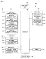
- Fig. 1 is a block diagram for explaining a mobile terminal according to an embodiment
- Figs. 2 and 3 are conceptive views illustrating examples of the mobile terminal when viewed in directions different from each other.
- a mobile terminal 100 may include a wireless communication unit 110, an input unit, a sensing unit 140, an output unit 150, an interface unit 160, a memory 170, a controller 180, and a power supply unit 190.
- the constituents of Fig. 1 are not essential constituents for embodying the mobile terminal. That is, the mobile terminal described in this specification may further include additional constituents in addition to the above-described constituents, or portions of the above-described constituents may be omitted in the mobile terminal described in this specification.
- the wireless communication unit 110 of the constituents may include at least one module for wirelessly communicating between the mobile terminal 100 and a wireless communication system, between the mobile terminal 100 and the other mobile terminal, or between the mobile terminal 100 and an external server. Also, the wireless communication unit 110 may include at least one module connecting the mobile terminal 100 to at least one network.
- the wireless communication unit 110 may include at least one of a broadcast receiving module 111, a mobile communication module 112, a wireless internet module 113, a short-range communication module 114, and a location information module 115.
- the input unit may include a camera 121 or an image input unit for inputting an image signal, a microphone 122 or an audio input unit for inputting an audio signal, and a user input unit 123 (for example, a touch key and a mechanical key) for receiving information from a user.
- Voice data or image data collected in the input unit 120 may be analyzed and then processed as a control command of the user.
- the sensing unit 140 may include at least one sensor for sensing at least one of information within the mobile terminal 100 and surrounding environment information surrounding the mobile terminal 100.
- the sensing unit 140 may include a proximity sensor 141, an illumination sensor 142, a touch sensor, an acceleration sensor, a magnetic sensor, a G-sensor, a gyroscope sensor, a motion sensor, an RGB sensor, an infrared sensor (IR sensor), a finger scan sensor, an ultrasonic sensor, an optical sensor (for example, the camera (see reference numeral 121)), a microphone (see reference numeral 122), a battery gauge, an environment sensor (for example, a barometer, a hygrometer, a thermometer, a radioactive detection sensor, a thermal detection sensor, a gas detection sensor, and the like), and a chemical sensor (for example, an E-nose, a health care sensor, a biometrics sensor, and the like).
- the mobile terminal disclosed in this specification may utilize information generated by combining information that are sensed by at least two
- the output unit 150 may generate a visual, auditory, or haptic output.
- the output unit 150 may include at least one of a display 151, an audio output module 152, a haptic module 153, and an optical output module 154.
- the display 151 may form a layered structure together with the touch sensor or be integrated with the touch sensor to realize a touch screen.
- the touch screen may serve as a user input unit 123 that provides an input interface between the mobile terminal 100 and the user and also provide an output interface between the mobile terminal 100 and the user.
- the interface unit 160 may serve as a passage for various kinds of external devices connected to the mobile terminal 100.
- the interface unit 160 may include at least one of a wired/wireless headset, an external charger port, a wired/wireless data port, a memory card port, a port for connecting a device including an identification module, an audio input/output (I/O) port, a video I/O port, and an earphone port.
- the mobile terminal 100 may perform a suitable control related to a connected external device when the external device is connected to the interface unit 160.
- the memory 170 stores data that supports various functions of the mobile terminal 100.
- the memory 170 may store a plurality of application programs or applications that are driven in the mobile terminal 100, data for operating the mobile terminal 100, and commands. At least a portion of the application programs may be downloaded from an external server through wireless communication. At least a portion of the application programs may be provided in the mobile terminal 100 from the release of the mobile terminal 100 to realize perform fundamental functions (for example, a phone receiving/transmitting function and a message receiving/transmitting function) of the mobile terminal 100.
- the application programs may be stored in the memory 170 and installed in the mobile terminal 100 and thus be driven to perform an operation (or function) of the mobile terminal 100 by the controller 180.
- the controller 180 may generally control the overall operation of the mobile terminal 100 in addition to the operation related to the application programs.
- the controller 180 may process signals, data, or information which are inputted or outputted through the above-described constituents or drive the application program stored in the memory 170 to provide or process information or functions suitable for the user.
- controller 180 may control at least a portion of the constituents of Fig. 1 to drive the application programs stored in the memory 170. Furthermore, the controller 180 may combine and operate at least two constituents of the mobile terminal 100 to drive the application program.
- the power supply unit 190 may receive power from an external power source or an internal power source under the control of the control unit (180) to supply the power to each of the constituents of the mobile terminal 100.
- the power supply unit 190 may include a battery.
- the battery may be a built-in battery or a replaceable battery.
- At least a portion of the constituents may cooperate with each other to realize the operation, control, or control method of the mobile terminal according to various embodiments that will be described below. Also, the operation, control, or control method of the mobile terminal 100 may be realized in the mobile terminal 100 by the driving of at least one application program stored in the memory 170.
- the mobile terminal 100 disclosed herein includes a bar-shaped terminal body.
- the present disclosure Is not limited thereto.
- the mobile terminal according to an embodiment may be applied to various structures such as a watch type, a clip type, a glass type, a folding type in which at least two bodies are relative-movably coupled to each other, a flip type, a slide type, a swing type, a swivel type, and the like.
- a specific type of mobile terminals or description with respect to the specific type of mobile terminals may be generally applied to different types of mobile terminals.
- the terminal body may be understood as a concept that is called at least one assembly of the mobile terminal 100.
- the mobile terminal 100 includes a case (for example, a frame, a housing, and a cover) defining an outer appearance thereof. As illustrated in Figs. 2 and 3 , the mobile terminal 100 may include a front case 101 and a rear case 102. Various electronic components may be disposed in an inner space that is defined by coupling the front case 101 and the rear case 102. At least one middle case may be additionally disposed between the front case 101 and the rear case 102.
- the electronic components may be mounted on the rear case 102.
- the electronic components that are capable of being mounted on the rear case 102 may include a detachable battery, an identification module, and a memory card.
- a rear surface case 103 for covering the mounted electronic components may be detachably coupled to the rear case 102.
- the rear surface case 103 may be detachably coupled to a rear surface of an assembly of the front case 101 and the rear case 102.
- the rear surface case 103 When the rear surface case 103 is coupled to the rear case 102, a portion of a side surface of the rear case 102 may be exposed. In some case, when the rear surface case 103 is coupled, the rear case 102 may be completely covered by the rear surface case 103. An opening for exposing a camera 121b or an audio output module 152b may be defined in the rear surface case 103.
- the assembly formed by coupling the front case 101, the rear case 102, and the rear surface case 103 to each other may be defined as the terminal body 100a.
- a reference numeral may be given to the terminal body 100a to describe the terminal body 100a.
- the terminal body 100a may have a front surface.
- the mobile terminal may include a window 151a.
- the window 151a is disposed at the front surface of the terminal body 100a, the window 151a has a front surface and a rear surface.
- the window 151a may be mounted on the front case 101 to define a front surface of the terminal body 100a together with the front case 101.
- the display 151 may be disposed on a rear surface of the window 151a to output an image through the window 151a.
- the window 151a and the display 151 may be mounted on the front surface of the terminal body 100a.
- Each of the cases 101, 102, and 103 constituting the terminal body 100a may be injection-molded by using a synthetic resin or be formed of metal, for example, stainless steel (STS), aluminum (Al), titanium (Ti), and the like.
- STS stainless steel
- Al aluminum
- Ti titanium
- the inner space may be defined by using one case.
- the mobile terminal 100 including a uni-body in which the synthetic resin or metal is continuously formed from a side surface to a rear surface may be realized.
- the mobile terminal 100 may include a waterproof part for preventing water from being permeated into the terminal body 100a.
- the waterproof part may include a waterproof member that is disposed between the window 151a and the front case 101, between the front case 101 and the rear case 102, or between the rear case 102 and the rear surface case 103 to seal the inner space when the above-described cases are coupled to each other.
- the mobile terminal 100 may include the display 151, first and second audio output modules 152a and 152b, a proximity sensor 141, an illumination sensor 142, an optical output module 154, first and second cameras 121a and 121b, first to third manipulation units 123a, 123b, and 123c, a microphone 122, and an interface unit 160.
- the mobile terminal 100 in which the display 151, the first audio output module 152a, the proximity sensor 141, the illumination sensor 142, the optical output module 154, the first camera 121a, the first manipulation unit 123a are disposed on the front surface of the terminal body 100a, and the second manipulation unit 123b, the microphone 122, and the interface unit 160 may be disposed on the side surface of the terminal body 100a, and the second audio output module 152b, the second camera 121b, the third manipulation unit 123c, and a flash 124 are disposed on the rear surface of the terminal body 100a is described as an example.
- the constituents are not limited to the above-described location. As necessary, each of the constituents may be omitted, replaced, or disposed on the other surface.
- the first manipulation unit 123a may not be disposed on the front surface of the terminal body 100a
- the second audio output module 152b may not be disposed the rear surface of the terminal body 100a, but be disposed on the side surface of the terminal body 100a.
- the display 151 displays (outputs) information that is processed in the mobile terminal 100.
- the display 151 may display execution screen information driven in the mobile terminal 100 or user interface (UI) or graphic user interface (GUI) information according to the execution screen.
- UI user interface
- GUI graphic user interface
- the display 151 may include at least one of a liquid crystal display (LCD), a thin film transistor-liquid crystal display (TFT LCD), an organic light-emitting diode (OLED), a flexible display, a 3D display, and an E-ink display.
- LCD liquid crystal display
- TFT LCD thin film transistor-liquid crystal display
- OLED organic light-emitting diode
- flexible display a 3D display
- 3D display a 3D display
- E-ink display E-ink display.
- At least two displays 151 may be provided according to the realization configuration of the mobile terminal 100.
- the plurality of displays may be disposed on one surface so as to be separated from each other or be integrally disposed on the one surface.
- the displays may be disposed on surfaces different from each other.
- the display 151 may receive a control command in a touch manner or include a touch sensor for detecting touch on the display 151.
- the touch sensor may detect the touch, and the controller 180 may generate a control command corresponding to the touch according to the touch on the display 151.
- Contents inputted by the touch manner may include characters or figures or menu items that are capable of being indicated or designated in various modes.
- the touch sensor may have a film shape including a touch pattern and be disposed between the window 151a and a display on the rear surface of the window 151a.
- the touch sensor may be a metal wire that is directly patterned on the rear surface of the window 151a.
- the touch sensor may be integrated with the display.
- the touch sensor may be disposed on a substrate of the display or within the display.
- the display 151 may form a touch screen together with the touch sensor.
- the touch screen may function as a user input unit (see reference numeral 123 of Fig. 3 ).
- the touch screen may substitute at least a portion of functions of the first manipulation unit 123a.
- the first audio output module 152a may be realized as a receiver that transmits a call sound to a user's ear.
- the second audio output module 152b may be realized as a loud speaker that outputs various alarm sounds or multimedia play sounds.
- An audio hole for releasing sounds generated from the first audio output module 152a may be defined in the window 151a of the display 151.
- the sounds may be released along an assembly gap (for example, a gap between the window 151a and the front case 101) between structures.
- the hole that is independently formed to output sounds may be unseen or hid, and thus the mobile terminal may be more simplified in outer appearance.
- the optical output module 154 may output light for informing an occurrence of an event. Examples of the event may include message reception, call signal reception, unanswered call, alarm, schedule notification, email reception, information reception through application.
- the controller 180 may control the optical output module 154 to stop the output of the light when the user's event confirmation is detected.
- the first camera 121a processes an image frame of a static image or moving picture, which is obtained by an image sensor in a photograph mode or videotelephony mode.
- the processed image frame may be displayed on the display 151 and then stored in the memory 170.
- the first and second manipulation units 123a and 123b may be one example of the user input unit 123 that is manipulated to receive a command for controlling an operation of the mobile terminal 100 and be called a manipulating portion.
- the first and second manipulation units 123a and 123b may be adopted in various tactile manners in which a manipulation unit is capable of being manipulated to receive tactile feels such as touch, push, scroll, and the like.
- the first and second manipulation units 123a and 123b may be adopted in a manner in which a manipulation unit is manipulated without tactile feel of the user through proximity touch, hovering, and the like.
- the first manipulation unit 123a is provided as the touch key, the present disclosure is not limited thereto.
- the first manipulation unit 123a may be provided as the mechanical key or a combination of the touch key and the mechanical key.
- Contents inputted by the first and second manipulation units 123a and 123b may be various set.
- the first manipulation unit 123a may receive commands such as menu, home key, cancel, and search
- the second manipulation unit 123b may receive commands for adjustment in intensity of sound outputted from the first and second audio output modules 152a and 152b and conversion into a touch recognition mode of the display 151.
- a third manipulation unit 123c may be disposed on the rear surface of the terminal body 100a as another example of the user input unit 123.
- the third manipulation unit 123c may be manipulated to receive a command for controlling the operation of the mobile terminal 100.
- the input contents may be variously set.
- the third manipulation unit 123c may receive commands such as turn on/off of power, start, end, and scroll and commands such as adjustment in intensity of sound outputted from the first and second audio output modules 152a and 152b and conversion into a touch recognition mode of the display 151.
- the third manipulation unit 123c may be realized in a shape in which the touch input, the push input, or a combination thereof is enabled.
- the third manipulation unit 123c may be disposed to overlap the display 151 disposed on the front surface of the terminal body 100a in a thickness of the terminal body 100a. For example, when the user holds the terminal body 100a by using one hand, the third manipulation unit 123c may be disposed on an upper end of the rear surface of the terminal body 100a so that the user manipulates the third manipulation unit 123c by using an index finger.
- the present disclosure is not limited thereto.
- the third manipulation unit 123c may be changed in position.
- the third manipulation unit 123c When the third manipulation unit 123c is disposed on the rear surface of the terminal body 100a, a new user interface using the third manipulation unit 123c may be realized. Also, the touch screen or the third manipulation unit 123c, which are described above may perform at least a portion of the functions of the first manipulation unit 123a disposed on the front surface of the terminal body 100a. As a result, when the first manipulation unit 123a is not disposed on the front surface of the terminal body 100a, the display 151 may have a larger screen.
- the mobile terminal 100 may include a fingerprint recognition sensor for recognizing a fingerprint of the user.
- the controller 180 may use fingerprint information detected through the fingerprint recognition sensor as an identification unit.
- the fingerprint recognition sensor may be built in the display 151 or the user input unit 123.
- the microphone 122 may receive user's voice and other sounds.
- the microphone 122 may be provided in plurality to receive stereo sounds.
- the interface unit 160 may serve as a passage for connecting the mobile terminal 100 to the external device.
- the interface unit 160 may include at least one of a connection terminal for connecting the other device (e.g., an earphone, an external speaker, and the like), a port for short-range communication (e.g., an infrared port (IrDA port), Bluetooth port, wireless LAN port, and the like), and a power supply terminal for supplying a power to the mobile terminal 100.
- the interface unit 160 may be realized in the form of a socket that is capable of accommodating a subscriber identification module (SIM) or user identity module (UIM) and an external card such as a memory card for storing information.
- SIM subscriber identification module
- UIM user identity module
- the second camera 121b may be disposed on the rear surface of the terminal body 100a. In this case, the second camera 121b may photograph a side substantially opposite to that photographed by the first camera 121a.
- the second camera 121b may include a plurality of lenses that are arranged along at least one line.
- the plurality of lenses may be arranged in a matrix form.
- the camera may be called an "array camera".
- the second camera 121b may photograph a subject in various manners by using the plurality of lenses to acquire more improved images.
- the flash 124 may be disposed adjacent to the second camera 121b.
- the flash 124 may irradiate light toward a subject when the subject is photographed by using the second camera 121b.
- the second audio output module 152b may be additionally disposed on the terminal body 100a.
- the second audio output module 152b may perform a stereo function together with the first audio output module 152a.
- the second audio output module 152 may be used for realizing a speakerphone mode.
- At least one antenna for wireless communication may be disposed on the terminal body 100a.
- the antenna may be built in the terminal body 100a or disposed on the terminal body 100a.
- the antenna constituting a portion of a communication receiving module may be withdrawably disposed in the terminal body 100a.
- the power supply unit (see reference numeral 190 of Fig. 1 ) for supplying a power to the mobile terminal 100 is disposed on the terminal body 100a.
- the power supply unit 190 may be built in the terminal body 100a or include a battery 191 that is detachably disposed on an outer portion of the terminal body 100a.
- the battery 191 may receive a power through a power cable connected to the interface unit 160. Also, the battery 191 may be wirelessly charged through a wireless charger.
- the wireless charging may be realized by a magnetic induction manner or resonant manner (magnetic resonance manner).
- the rear surface case 103 is coupled to the rear case 102 to cover the battery 191, thereby preventing the battery 192 from being separated and protecting the battery 192 against an external impact and foreign substances.
- the rear surface case 103 may be detachably coupled to the rear case 102.
- An accessory for protecting the outer appearance of the mobile terminal 100 or assisting or expanding the functions of the mobile terminal 100 may be additionally disposed on the mobile terminal 100.
- Examples of the accessory may include a cover or pouch for covering or accommodating at least one surface of the mobile terminal 100.
- the cover or pouch may communicate with the display 151 to expand the functions of the mobile terminal 100.
- Fig. 4 is a front view of the mobile terminal according to an embodiment
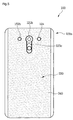
- Fig. 5 is a rear view of the mobile terminal according to an embodiment
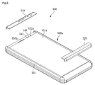
- Fig. 6 is an exploded perspective view of the external cover and the mobile terminal according to an embodiment
- Fig. 7 is a side cross-sectional view of the mobile terminal according to an embodiment.
- the mobile terminal 100 includes an external cover 200 coupled to the terminal body 100a defining the outer appearance of the mobile terminal 100 to protect the outer appearance of the terminal body 100a.
- Tn external cover 200 may be coupled to an outer surface of the terminal body 110a to protect an outer appearance of the terminal body 110a
- the external cover 200 may include a front cover that covers at least one outer surface of a top surface of the terminal body, a bottom surface of the terminal body, a left of the terminal body, or a right surface of the terminal body and a portion of the front surface of the window 151a.
- the front covers 210 and 220 may cover an outer surface of the terminal body 100a, i.e., an outer surface of the front case 101 and an outer surface of the rear case 102 and a portion of the front surface of the window 151a.
- the external cover 200 may further include a rear cover 240 coupled to the rear surface of the terminal body 100a to cover the rear surface of the terminal body 100a.
- the rear cover 240 may be coupled to a rear surface of the rear surface case 103 to cover a rear surface of the rear surface case 103.
- the rear cover 240 may be coupled to the rear surface case 103 to cover the entire rear surface of the rear surface case 103.
- An exposing hole for exposing the second audio output module 152b, the second camera 121b, the third manipulation unit 123c, and the flash 124, which are disposed on the rear surface of the terminal body 100a, to the outside may be defined in the rear cover 240.
- the front covers 210 and 220 includes a first cover 210 for covering one side surface of the outer surface of the terminal body 100a and one side of the front surface of the window 151a and a second cover 220 for covering the other side surface of the outer surface of the terminal body 100a and the other side of the front surface of the window 151a.
- the first cover 210 and the second cover 220 may be vertically disposed symmetric to each other. As illustrated in Fig. 6 , the first cover 210 may cover the top surface of the terminal body 100a and an upper front surface of the window 151a, and the second cover 220 may cover the bottom surface of the terminal body 100a and a lower front surface of the window 151a.
- first and second covers 210 and 220 may be horizontally disposed symmetric to each other.
- the first cover 210 may cover the left surface and a left front surface of the terminal body 100a
- the second cover 220 may cover the right surface and a right front surface of the terminal body 100a.
- the front covers 210 and 220 may be vertically disposed to surround the outer surface of the terminal body 100a from the front surface of the terminal body 100a including the window 151a.
- the rear case 102 of the terminal body 100a may not be exposed to the outside of the mobile terminal 100.
- the front covers 210 and 220 may be coupled to cover each of an upper front surface, a lower front surface, a top surface, and a bottom surface of the front case 101.
- the external cover 200 may be manufactured by using a material having a soft and easily deformable characteristic such as natural leather, synthetic leather, or fabric.
- the external cover 200 may have inner and outer surfaces, which are formed of materials different from each other.
- the inner surface may be formed of a soft material so that the inner surface is easily attached, and the outer surface may be formed of a leather material.
- the mobile terminal 100 may not be increased very much in thickness to maintain user's grip feeling with respect to the mobile terminal 100.
- the external cover 200 includes all of the front covers 210 and 220 and the rear cover 240, all of the upper front surface, the top surface, the lower front surface, the bottom surface, and the rear surface of the terminal body 100a may be covered.
- the external cover 200 may maximally increase an area for protecting the mobile terminal 100 against the external impact or the foreign substances.
- Fig. 8 is an enlarged cross-sectional view of a portion A of Fig. 7
- Fig. 9 is an exploded cross-sectional view of the front cover and the mobile terminal according to an embodiment
- Fig. 10 is a perspective view of a state in which the front case and the front cover are coupled to each other according to an embodiment
- Fig. 11 is an enlarged view of a portion C of Fig. 8
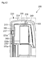
- Fig. 12 is a cross-sectional view of a region B of Fig. 7 .
- the first cover 210 and the second cover 220 may include a main body for covering the front surface of the window 151a and a covered part that is covered backward from an end of the body to cover the top surface of the terminal body 100a or the bottom surface of the terminal body 100a.
- a coupling groove that is recessed backward by a predetermined distance to form a stepped portion with respect to the other area may be defined in an area of the front surface of the window 151a, which is coupled to the body.
- the main body may be seated in the coupling groove.
- a coupling sheet that provides an adhesion force on both surfaces thereof to allow a seating surface of the coupling groove and a rear surface of the main body to adhere thereto may be disposed between the coupling groove and the main body.
- the coupling sheet may be formed of a material having relatively high rigidity than that of the main body.
- At least one through hole may be defined in the coupling sheet to pass through front and rear surfaces of the coupling sheet. The sum of a thickness of the coupling sheet and a thickness of the main body may correspond to a recessed height of the coupling groove.
- An adhesion part for coupling the end of the main body to the window 151a may be disposed on an area on which the stepped portion of the window 151a is formed.
- the adhesion part may be epoxy that is applied to the area on which the stepped portion of the window 151a is formed.
- the second cover 220 includes a first body 222 for covering the front surface of the mobile terminal 100 and a first covered part 224 that is curved from an end of the first body 222 to a rear side of the terminal body 100a to cover the outer surface of the front case 101.
- a coupling groove 151b that is recessed backward may be defined in an area of the front surface of the window 151a to which the first body 222 is coupled.
- the coupling groove 151b may be stepped from the other area on the front surface of the window 151a.
- the first body 222 is coupled to the coupling groove 151b. That is, the first body 222 is placed on the seating surface 151c of the coupling groove 151b.
- the display 151 for outputting an image is disposed at a rear side of the window 151a, and the display 151 has to have a length less than that of the window 151a to output the image.
- the coupling groove 151b that is a stepped area may be defined in the window 151a to maintain a ratio of the window 151a to the display 151, thereby securing a space in which the electronic components are disposed in a rear space of the window 151a. That is to say, the first body 222 may be coupled to the front surface of the window 151a to allow the window 151a to have a length greater than that of the display 151.
- An adhesion part 270 for coupling the end of the first body 222 to the stepped area of the window 151a may be disposed on the area of the front surface of the window 151a on which the stepped portion is formed. Since the end of the first body 222 has relatively weak adhesion force than that of the other area, the adhesion part 270 may be disposed on the end area to prevent the first body from being lifted.
- the adhesion part 270 may be epoxy that is applied to the area on which the stepped portion of the window 151a is formed.
- a coupling sheet 260 to be coupled to the rear surface of the first body 222 is disposed at a rear side of the first body 222.
- the coupling sheet 260 may be formed of a material having relatively high rigidity than that of the first body 222.
- the first body 222 may be firmly coupled to the seating surface 151c.
- the sum of a thickness of the coupling sheet 260 and a thickness of the first body 222 may correspond to a height of the coupling groove 151b.
- the first body 222 may form a sense of unity with the window 151a on the front surface of the mobile terminal 100.
- An adhesive for providing the adhesion force to each of the seating surface 151c and the rear surface of the first body 222 may be applied on both side surfaces of the coupling sheet 260.
- the first curved part 224 is curved backward from a lower end of the first body 222 to cover the bottom surface of the front case 101.
- a coupling groove 101a into which the first curved part 224 is inserted may be defined in the bottom surface of the front case 101. Since the first curved part 224 is seated in the coupling groove 101a, a sense of unity with the other area of the front case 101 may be provided.
- a user manipulation unit for inputting a user's manipulation command through the touch may be disposed on the lower front surface of the window 151a that is covered by the external cover 200.
- a manipulation command may be inputted to the user manipulation unit.
- a touch screen for the user manipulation may be disposed on the front surface of the window 151a that is covered by the first body 222 of the second cover 220.
- the first body 222 of the second cover 220 may cover the lower front surface of the window 151a, and the first body 220 of the second cover 222 may be touched to perform the touch input of the user manipulation unit.
- the manipulation command inputted by touching the top surface of the first body 222 by the user may be transmitted to the touch screen through the first body 222 to perform an operation of the mobile terminal 100, which corresponds to the user input.
- the first cover 210 may include a second body 212 for covering the front surface of the mobile terminal 100 and a second curved part 214 that is covered from an end of the second body 212 to a rear side of the mobile terminal 100 to cover the top surface of the front case 101.
- the first cover 210 may include a bent part 216 that is bent from an end of the second cover part 214 to cover a portion of the rear surface of the front case 101.
- a coupling groove 151b that is recessed backward may be defined in an area of the front surface of the window 151a to which the second body 212 is coupled.
- the coupling groove 151b may be stepped from the other area on the front surface of the window 151a.
- the second body 212 is coupled to the coupling groove 151b.
- an adhesion part 270 may be disposed on the stepped area of the window 151a to which the end of the second body 212 is coupled.
- a coupling sheet 260 coupled to the rear surface of the second body 212 may be disposed at a rear side of the second body 212.
- the sum of thicknesses of the second body 212 and the coupling sheet 260 may correspond to a height of the coupling groove 151b.
- the front surface of the mobile terminal 100 may have a sense of unity.
- the mobile terminal may include a constituent (e.g., the camera 121a) that passes through the second body 212 and the coupling sheet 260 at the same time and is disposed on the front surface of the mobile terminal 100.
- Exposing holes 217 and 262 for exposing the constituent 121a disposed on the front surface of the mobile terminal 100 as described above may be defined in the second body 212 and the coupling sheet 260.
- the through hole 262 of the coupling sheet 260 may be the exposing hole for exposing the constituent (e.g., the camera 121a) disposed on the front surface of the mobile terminal 100 to the outside.
- the coupling groove (the first coupling groove) into which the first cover 210 is inserted and coupled is defined in the upper portion of the window 151a according to the current embodiment so as to be recessed backward by a predetermined distance.
- the coupling groove (the second coupling groove) into which the second cover 220 is inserted and coupled may be defined in the lower portion of the window 151a so as to be recessed backward by a predetermined distance.
- the other area disposed between the coupling groove (the first coupling groove) defined in the upper portion of the window 151a and the coupling groove (the second coupling groove) defined in the lower portion of the window 151a together with each of the coupling grooves may form the stepped portion.
- the other area may not be covered by the external cover 200, but be exposed to the outside.
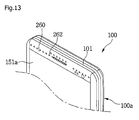
- Fig. 13 is a perspective view of a state in which the coupling sheet and the front case are coupled to each other according to an embodiment.
- a through hole 262 passing through front and rear surfaces of the coupling sheet 260 may be defined in the coupling sheet 260.
- the through hole 262 may be provided in plurality in the coupling sheet 260.
- the plurality of through holes 262 may be spaced apart from each other.
- An adhesive for coupling the coupling sheet 260 to the front case 101 may be applied to the rear surface of the coupling sheet 260 or the seating surface 151c of the coupling groove 151b.
- the coupling sheet 260 and the front case 101 may be firmly coupled to each other.
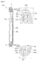
- Fig. 14 is a side cross-sectional view of a mobile terminal according to another embodiment
- Fig. 15 is s perspective view of a portion A of Fig. 14 .
- a mobile terminal 100 in the current embodiment may include an external cover 200 and an appearance sheet 250.
- the external cover 200 and the appearance sheet 250 may have a structure and effect that are equal or similar to those according to the foregoing embodiment, and thus, their duplicated description will be omitted, and the same reference numeral may be given.
- the external cover 200 may be disposed outside a terminal body 100a and define a portion of an outer appearance of the mobile terminal 100.
- the external cover 200 may define a portion of the outer appearance of the mobile terminal.
- a window 151a and the terminal body 100a may define the remaining outer appearance of the mobile terminal.
- the external cover 200 may include a main body 301 disposed at a rear side of a rear surface of the terminal body 100a and extension parts 310 and 320 extending from the main body to a front side of the terminal body 100a to cover a portion of a front surface of the terminal body 100a.
- the extension parts 310 and 320 may include an upper extension part 310 disposed above the window 151a and the terminal body 100a and a lower extension part 320 disposed under the window 151a and the terminal body 100a.
- the upper extension part 310 may include a top surface extension part that is bent from an upper end of the main body 301 and then disposed above the terminal body 100a and a front surface upper extension part extending from the top surface extension part downward.
- the lower extension part 320 may include a bottom surface extension part that is bent from a lower end of the main body 301 and then disposed under the terminal body 100a and a front surface lower extension part extending from the bottom surface extension part upward.
- the appearance sheet 250 may be disposed between the external cover 300 and the terminal body 100a to define an outer appearance of the external cover 200.
- the external cover 200 may be supported by the appearance sheet 250 and thus maintained in outer appearance thereof.
- the appearance sheet 250 may have one surface that is coupled to the terminal body 100a and the other surface that is coupled to the external cover 200.
- the appearance sheet 250 may be coupled to an inner surface of the external cover 200 to maintain a shape of the external cover 200 outside the terminal body 100a.
- the external cover 200 may be formed of a soft material. If the external cover 200 is directly coupled to the terminal body 100a, coupling force therebetween may be weak. That is, even though an adhesive is applied to the entire inner surface of the external cover 200 or an edge of the external cover 200, if an object for supporting the external cover 200 is not provided, the coupling process may be difficult, and also, creases may be generated on the external cover 200.
- the appearance sheet 250 for defining the outer appearance of the external cover 200 may be disposed between the terminal body 100a and the external cover 200 to firmly maintain the coupled state of the external cover 200 on the terminal body 100a.
- the appearance sheet 250 may serve as an external cover support for supporting the external cover 200.
- the appearance sheet 250 may have an outer surface corresponding to a shape of the inner surface of the external cover 200. Thus, the entire outer surface of the appearance sheet 250 may adhere to the entire inner surface of the external cover 200.
- the appearance sheet 250 may be formed of a material having relatively higher rigidity than that of the external cover 200 to reinforce the rigidity of the external cover 200.
- the appearance sheet 250 may be formed of a material that is selected from the group consisting of carbon fiber-reinforced plastic (CFRP), class fiber-reinforced plastic, and metal.
- the external cover 200 further include bent parts 312 and 322 that are bent from ends of the extension parts 310 and 320 to the rear side of the mobile terminal 100.
- the bent parts 312 and 322 may be bent from an end of the upper extension part 310 disposed on an upper portion of the front surface of the terminal body 100a to the rear side of the terminal body 100a and bent from an end of the lower extension part 320 disposed on a lower portion of the front surface of the terminal body 100a to the rear side of the mobile terminal 100.
- the bent part that is bent from the end of the upper extension part 310 may be an upper bent part 312, and the bent part that is bent from the end of the lower extension part 320 may be a lower bent part 322.
- the upper bent part 312 and the lower bent part 322 may be vertically spaced apart from each other to define a space therebetween.
- the window 151a may be disposed on an area that is defined by the upper bent part 312 and the lower bent part 322. That is to say, the window 151a may have an upper end that contacts an outer surface of the upper bent part 312 and a lower end that contacts an outer surface of the lower bent part 322. A portion of the front surface of the mobile terminal 100 may be defined between the upper bent part 312 and the lower bent part 322.
- an area of the front surface of the mobile terminal 100 except for the window 151a may be covered by the external cover 200, and an area to be protected by the external cover 200 may be expanded.
- the window 151a in which a manipulation command is inputted through user's touch may have a boundary by the external cover 200 to allow the outer appearance of the mobile terminal 100 to be elegant.
- the appearance sheet 250 may include a plurality of appearance sheet bent parts 351 and 352 that are bent backward to correspond to the upper and lower bent parts 312 and 322.
- the plurality of appearance sheet bent parts 351 and 352 may include an upper appearance sheet bent part 351 that is bent to face the upper bent part 312 and covered by the upper bent part 312 and a lower appearance sheet bent part 252 that is bent to face the lower bent part 322 and covered by the lower bent part 322.
- the external cover 200 may prevent the upper bent part 312 from being lifted. Also, in a state where an outer (i.e., a bottom surface) of the lower bent part 322 contacts the lower end of the window 151a, since an Inner surface (i.e., a bottom surface) of the lower bent part 322 contacts the other one of the appearance sheet bent parts 351 and 352, the external cover 200 may prevent the lower bent part 322 from being lifted.
- Figs. 16 to 19 are diagrams illustrating a coupling process of the external cover according to another embodiment.
- the external cover 200 and the appearance sheet 250 may be coupled to each other. Since it is difficult to form a specific shape by using only the external cover 200 formed of the soft material, the external cover 200 may be coupled to the appearance sheet 250 formed of the material having the relatively high rigidity to reinforce the rigidity of the external cover 200.
- the external cover 200 and the appearance sheet 250 may be coupled by using a laminating manner using a tape for providing adhesion force or an adhesion material and high pressure.
- the appearance sheet 250 coupled to the external cover 200 may have a shape corresponding to that of the terminal body 100a.
- the shape may be formed by punching a hole to match the outer appearance of the mobile terminal 100 that is designed by applying press and forming methods and then forming the extension parts 310 and 320 and the bent parts 312 and 322.
- a specific material may be injected into the appearance sheet 250 by using a mold to form the terminal body 100a. That is to say, a material for the terminal body 100a may be injected into the mold having a shape of the designed terminal body and then molded. Then, the terminal body 100a to which the external cover 200 is coupled may be integrally injection-molded.
- the terminal body 100a, the external cover 200, and the appearance sheet 250 may be integrally injection-molded to simplify the manufacturing process. Also, an error in dimension due to a separate manufacturing process may be prevented, and manufacturing costs of the mobile terminal 100 may be reduced.
- Fig. 20 is a perspective view of a state in which the mobile terminal drops according to another embodiment
- Fig. 21 is a cross-sectional view illustrating an internal state of the mobile terminal when the mobile terminal drops according to another embodiment.
- the mobile terminal 100 may reduce the impact applied from the outside by the appearance sheet 250 and the external cover 200, which are coupled to the outer surface of the mobile terminal 100a.
- the external cover 200 is formed of the soft material such as the leather, when the impact is applied to the outer surface of the mobile terminal 100, the impact may be reduced by the self-elastic force of the external cover 200. Also, in case of the leather material, there is no fear of breaking or stabbing of the surface even through the mobile terminal drops. Thus, the surface of the mobile terminal 100 may be maintained in the clean state.
- the appearance sheet 250 formed of a metal material having the relatively high rigidity than that of the external cover 200 may be disposed inside the external cover 200 to realize a secondary impact reducing structure. That is, the external cover 200 may prevent the surface of the mobile terminal 100 from being damaged, and the appearance sheet 250 may prevent the impact from being transmitted into the mobile terminal 100.
- the mobile terminal according to the embodiments may have the following effects.
- the external cover covers a portion of the front surface of the mobile terminal in addition to the outer surface of the mobile terminal, the area that is capable of protecting the mobile terminal against the external impact and the foreign substances may be expanded.
- the coupling groove is defined in the top surface of the window, and the external cover is seated in the coupling groove, the large-scale window may be maintained. Also, the external cover may be firmly coupled to the front surface of the window by the coupling sheet disposed between the external cover and the coupling groove.
- the external cover is formed of a leather material, the outer appearance of the mobile terminal may be more refined.
Applications Claiming Priority (2)
| Application Number | Priority Date | Filing Date | Title |
|---|---|---|---|
| KR1020150098446A KR20170006957A (ko) | 2015-07-10 | 2015-07-10 | 이동 단말기 |
| KR1020150098479A KR20170006972A (ko) | 2015-07-10 | 2015-07-10 | 이동 단말기 |
Publications (2)
| Publication Number | Publication Date |
|---|---|
| EP3116202A1 true EP3116202A1 (de) | 2017-01-11 |
| EP3116202B1 EP3116202B1 (de) | 2018-03-07 |
Family
ID=55966964
Family Applications (1)
| Application Number | Title | Priority Date | Filing Date |
|---|---|---|---|
| EP16000969.2A Not-in-force EP3116202B1 (de) | 2015-07-10 | 2016-04-29 | Mobiles endgerät |
Country Status (3)
| Country | Link |
|---|---|
| US (1) | US9768821B2 (de) |
| EP (1) | EP3116202B1 (de) |
| CN (1) | CN106341500A (de) |
Families Citing this family (9)
| Publication number | Priority date | Publication date | Assignee | Title |
|---|---|---|---|---|
| KR20190131526A (ko) * | 2017-03-19 | 2019-11-26 | 사빅 글로벌 테크놀러지스 비.브이. | 얇은 고강성 라미네이트, 이를 포함하는 휴대용 전자 장치 하우징 및 이와 같은 라미네이트 및 휴대용 전자 장치 하우징을 제조하기 위한 방법 |
| KR20180109292A (ko) * | 2017-03-27 | 2018-10-08 | (주)화이트스톤 | 스마트 기기의 디스플레이부 보호 및 재생 기능을 갖는 프로텍터, 이의 부착기재 및 부착방법 |
| KR101958667B1 (ko) * | 2017-09-08 | 2019-03-15 | 엘지전자 주식회사 | 이동 단말기 |
| US10897074B2 (en) | 2017-09-30 | 2021-01-19 | Guangdong Oppo Mobile Telecommunications Corp., Ltd. | Housing, method for manufacturing housing, and mobile terminal |
| KR102392246B1 (ko) * | 2017-11-13 | 2022-04-29 | 삼성전자주식회사 | 방수 구조를 가지는 전자 장치 |
| CN113411473B (zh) * | 2018-03-20 | 2023-09-26 | 华为技术有限公司 | 一种终端 |
| CN108924336A (zh) * | 2018-04-27 | 2018-11-30 | 努比亚技术有限公司 | 一种终端控制方法、柔性屏终端及计算机可读存储介质 |
| CN108810199B (zh) * | 2018-06-01 | 2021-01-12 | Oppo广东移动通信有限公司 | 显示屏组件、电子设备及显示控制方法 |
| US11442507B2 (en) * | 2020-06-02 | 2022-09-13 | Getac Technology Corporation | Mobile electronic device |
Citations (6)
| Publication number | Priority date | Publication date | Assignee | Title |
|---|---|---|---|---|
| US20120039023A1 (en) * | 2010-08-13 | 2012-02-16 | Nokia Corporation | Cover for an Electronic Device |
| US20130165190A1 (en) * | 2011-12-26 | 2013-06-27 | Samsung Electronics Co., Ltd. | Protection cover and portable apparatus having the same |
| US20130303241A1 (en) * | 2012-05-11 | 2013-11-14 | Motorola Mobility, Inc. | Method and device with a customizable key pad assembly |
| US20140045557A1 (en) * | 2012-08-10 | 2014-02-13 | Marware, Inc. | Mobile telephone case |
| US20150059251A1 (en) * | 2013-09-04 | 2015-03-05 | James A. Rinner | Portable electronic device privacy system |
| EP3024203A1 (de) * | 2014-11-21 | 2016-05-25 | Whitestone Co., Ltd. | Schutz für mobile elektronische vorrichtung |
Family Cites Families (3)
| Publication number | Priority date | Publication date | Assignee | Title |
|---|---|---|---|---|
| US9997751B2 (en) * | 2012-05-25 | 2018-06-12 | Incipio, Llc | Battery case for mobile device |
| US9537526B2 (en) * | 2013-08-30 | 2017-01-03 | Wimo Labs LLC | Door securement mechanism for waterproof encasement |
| US9161597B2 (en) * | 2013-09-12 | 2015-10-20 | Otter Products, Llc | Protective case with internal suspension system |
-
2016
- 2016-04-29 EP EP16000969.2A patent/EP3116202B1/de not_active Not-in-force
- 2016-05-20 CN CN201610341052.4A patent/CN106341500A/zh active Pending
- 2016-07-08 US US15/205,883 patent/US9768821B2/en not_active Expired - Fee Related
Patent Citations (6)
| Publication number | Priority date | Publication date | Assignee | Title |
|---|---|---|---|---|
| US20120039023A1 (en) * | 2010-08-13 | 2012-02-16 | Nokia Corporation | Cover for an Electronic Device |
| US20130165190A1 (en) * | 2011-12-26 | 2013-06-27 | Samsung Electronics Co., Ltd. | Protection cover and portable apparatus having the same |
| US20130303241A1 (en) * | 2012-05-11 | 2013-11-14 | Motorola Mobility, Inc. | Method and device with a customizable key pad assembly |
| US20140045557A1 (en) * | 2012-08-10 | 2014-02-13 | Marware, Inc. | Mobile telephone case |
| US20150059251A1 (en) * | 2013-09-04 | 2015-03-05 | James A. Rinner | Portable electronic device privacy system |
| EP3024203A1 (de) * | 2014-11-21 | 2016-05-25 | Whitestone Co., Ltd. | Schutz für mobile elektronische vorrichtung |
Also Published As
| Publication number | Publication date |
|---|---|
| US9768821B2 (en) | 2017-09-19 |
| CN106341500A (zh) | 2017-01-18 |
| US20170012659A1 (en) | 2017-01-12 |
| EP3116202B1 (de) | 2018-03-07 |
Similar Documents
| Publication | Publication Date | Title |
|---|---|---|
| EP3116202B1 (de) | Mobiles endgerät | |
| CN105094225B (zh) | 移动终端 | |
| KR102206242B1 (ko) | 이동 단말기 | |
| CN105450848A (zh) | 移动终端及其控制方法 | |
| CN107547699A (zh) | 移动终端 | |
| KR102152168B1 (ko) | 이동 단말기 | |
| EP3343884A1 (de) | Mobiles endgerät | |
| CN106506732B (zh) | 移动终端 | |
| KR102406843B1 (ko) | 이동 단말기 | |
| CN107925689A (zh) | 移动终端 | |
| KR20160016412A (ko) | 폴리오 케이스, 이동 단말기 및 그 제어방법 | |
| US20220357823A1 (en) | Mobile terminal for setting up home screen and control method therefor | |
| KR20170014629A (ko) | 이동 단말기 | |
| KR20170084811A (ko) | 이동 단말기 | |
| KR101578435B1 (ko) | 이동 단말기 | |
| KR102192820B1 (ko) | 이동 단말기 | |
| KR102159593B1 (ko) | 이동 단말기 | |
| US20220374145A1 (en) | Electronic device for outputting keyboard interface and control method therefor | |
| KR20180065174A (ko) | 단말기 케이스 및 이동 단말기 | |
| KR101607974B1 (ko) | 이동 단말기 | |
| KR20170083406A (ko) | 이동 단말기 | |
| KR102179824B1 (ko) | 이동 단말기 | |
| KR101635033B1 (ko) | 이동 단말기 | |
| KR102091162B1 (ko) | 이동 단말기 | |
| KR20170006957A (ko) | 이동 단말기 |
Legal Events
| Date | Code | Title | Description |
|---|---|---|---|
| PUAI | Public reference made under article 153(3) epc to a published international application that has entered the european phase |
Free format text: ORIGINAL CODE: 0009012 |
|
| STAA | Information on the status of an ep patent application or granted ep patent |
Free format text: STATUS: THE APPLICATION HAS BEEN PUBLISHED |
|
| AK | Designated contracting states |
Kind code of ref document: A1 Designated state(s): AL AT BE BG CH CY CZ DE DK EE ES FI FR GB GR HR HU IE IS IT LI LT LU LV MC MK MT NL NO PL PT RO RS SE SI SK SM TR |
|
| AX | Request for extension of the european patent |
Extension state: BA ME |
|
| STAA | Information on the status of an ep patent application or granted ep patent |
Free format text: STATUS: REQUEST FOR EXAMINATION WAS MADE |
|
| 17P | Request for examination filed |
Effective date: 20170619 |
|
| GRAP | Despatch of communication of intention to grant a patent |
Free format text: ORIGINAL CODE: EPIDOSNIGR1 |
|
| STAA | Information on the status of an ep patent application or granted ep patent |
Free format text: STATUS: GRANT OF PATENT IS INTENDED |
|
| INTG | Intention to grant announced |
Effective date: 20170920 |
|
| GRAS | Grant fee paid |
Free format text: ORIGINAL CODE: EPIDOSNIGR3 |
|
| GRAA | (expected) grant |
Free format text: ORIGINAL CODE: 0009210 |
|
| STAA | Information on the status of an ep patent application or granted ep patent |
Free format text: STATUS: THE PATENT HAS BEEN GRANTED |
|
| AK | Designated contracting states |
Kind code of ref document: B1 Designated state(s): AL AT BE BG CH CY CZ DE DK EE ES FI FR GB GR HR HU IE IS IT LI LT LU LV MC MK MT NL NO PL PT RO RS SE SI SK SM TR |
|
| REG | Reference to a national code |
Ref country code: GB Ref legal event code: FG4D |
|
| REG | Reference to a national code |
Ref country code: CH Ref legal event code: EP Ref country code: AT Ref legal event code: REF Ref document number: 977743 Country of ref document: AT Kind code of ref document: T Effective date: 20180315 |
|
| REG | Reference to a national code |
Ref country code: DE Ref legal event code: R096 Ref document number: 602016001756 Country of ref document: DE |
|
| REG | Reference to a national code |
Ref country code: IE Ref legal event code: FG4D |
|
| REG | Reference to a national code |
Ref country code: NL Ref legal event code: MP Effective date: 20180307 |
|
| REG | Reference to a national code |
Ref country code: LT Ref legal event code: MG4D |
|
| PG25 | Lapsed in a contracting state [announced via postgrant information from national office to epo] |
Ref country code: ES Free format text: LAPSE BECAUSE OF FAILURE TO SUBMIT A TRANSLATION OF THE DESCRIPTION OR TO PAY THE FEE WITHIN THE PRESCRIBED TIME-LIMIT Effective date: 20180307 Ref country code: LT Free format text: LAPSE BECAUSE OF FAILURE TO SUBMIT A TRANSLATION OF THE DESCRIPTION OR TO PAY THE FEE WITHIN THE PRESCRIBED TIME-LIMIT Effective date: 20180307 Ref country code: CY Free format text: LAPSE BECAUSE OF FAILURE TO SUBMIT A TRANSLATION OF THE DESCRIPTION OR TO PAY THE FEE WITHIN THE PRESCRIBED TIME-LIMIT Effective date: 20180307 Ref country code: HR Free format text: LAPSE BECAUSE OF FAILURE TO SUBMIT A TRANSLATION OF THE DESCRIPTION OR TO PAY THE FEE WITHIN THE PRESCRIBED TIME-LIMIT Effective date: 20180307 Ref country code: NO Free format text: LAPSE BECAUSE OF FAILURE TO SUBMIT A TRANSLATION OF THE DESCRIPTION OR TO PAY THE FEE WITHIN THE PRESCRIBED TIME-LIMIT Effective date: 20180607 Ref country code: FI Free format text: LAPSE BECAUSE OF FAILURE TO SUBMIT A TRANSLATION OF THE DESCRIPTION OR TO PAY THE FEE WITHIN THE PRESCRIBED TIME-LIMIT Effective date: 20180307 |
|
| REG | Reference to a national code |
Ref country code: AT Ref legal event code: MK05 Ref document number: 977743 Country of ref document: AT Kind code of ref document: T Effective date: 20180307 |
|
| PG25 | Lapsed in a contracting state [announced via postgrant information from national office to epo] |
Ref country code: BG Free format text: LAPSE BECAUSE OF FAILURE TO SUBMIT A TRANSLATION OF THE DESCRIPTION OR TO PAY THE FEE WITHIN THE PRESCRIBED TIME-LIMIT Effective date: 20180607 Ref country code: GR Free format text: LAPSE BECAUSE OF FAILURE TO SUBMIT A TRANSLATION OF THE DESCRIPTION OR TO PAY THE FEE WITHIN THE PRESCRIBED TIME-LIMIT Effective date: 20180608 Ref country code: SE Free format text: LAPSE BECAUSE OF FAILURE TO SUBMIT A TRANSLATION OF THE DESCRIPTION OR TO PAY THE FEE WITHIN THE PRESCRIBED TIME-LIMIT Effective date: 20180307 Ref country code: LV Free format text: LAPSE BECAUSE OF FAILURE TO SUBMIT A TRANSLATION OF THE DESCRIPTION OR TO PAY THE FEE WITHIN THE PRESCRIBED TIME-LIMIT Effective date: 20180307 Ref country code: RS Free format text: LAPSE BECAUSE OF FAILURE TO SUBMIT A TRANSLATION OF THE DESCRIPTION OR TO PAY THE FEE WITHIN THE PRESCRIBED TIME-LIMIT Effective date: 20180307 |
|
| PG25 | Lapsed in a contracting state [announced via postgrant information from national office to epo] |
Ref country code: NL Free format text: LAPSE BECAUSE OF FAILURE TO SUBMIT A TRANSLATION OF THE DESCRIPTION OR TO PAY THE FEE WITHIN THE PRESCRIBED TIME-LIMIT Effective date: 20180307 Ref country code: PL Free format text: LAPSE BECAUSE OF FAILURE TO SUBMIT A TRANSLATION OF THE DESCRIPTION OR TO PAY THE FEE WITHIN THE PRESCRIBED TIME-LIMIT Effective date: 20180307 Ref country code: AL Free format text: LAPSE BECAUSE OF FAILURE TO SUBMIT A TRANSLATION OF THE DESCRIPTION OR TO PAY THE FEE WITHIN THE PRESCRIBED TIME-LIMIT Effective date: 20180307 Ref country code: RO Free format text: LAPSE BECAUSE OF FAILURE TO SUBMIT A TRANSLATION OF THE DESCRIPTION OR TO PAY THE FEE WITHIN THE PRESCRIBED TIME-LIMIT Effective date: 20180307 Ref country code: IT Free format text: LAPSE BECAUSE OF FAILURE TO SUBMIT A TRANSLATION OF THE DESCRIPTION OR TO PAY THE FEE WITHIN THE PRESCRIBED TIME-LIMIT Effective date: 20180307 Ref country code: EE Free format text: LAPSE BECAUSE OF FAILURE TO SUBMIT A TRANSLATION OF THE DESCRIPTION OR TO PAY THE FEE WITHIN THE PRESCRIBED TIME-LIMIT Effective date: 20180307 |
|
| PG25 | Lapsed in a contracting state [announced via postgrant information from national office to epo] |
Ref country code: CZ Free format text: LAPSE BECAUSE OF FAILURE TO SUBMIT A TRANSLATION OF THE DESCRIPTION OR TO PAY THE FEE WITHIN THE PRESCRIBED TIME-LIMIT Effective date: 20180307 Ref country code: AT Free format text: LAPSE BECAUSE OF FAILURE TO SUBMIT A TRANSLATION OF THE DESCRIPTION OR TO PAY THE FEE WITHIN THE PRESCRIBED TIME-LIMIT Effective date: 20180307 Ref country code: SM Free format text: LAPSE BECAUSE OF FAILURE TO SUBMIT A TRANSLATION OF THE DESCRIPTION OR TO PAY THE FEE WITHIN THE PRESCRIBED TIME-LIMIT Effective date: 20180307 Ref country code: SK Free format text: LAPSE BECAUSE OF FAILURE TO SUBMIT A TRANSLATION OF THE DESCRIPTION OR TO PAY THE FEE WITHIN THE PRESCRIBED TIME-LIMIT Effective date: 20180307 |
|
| REG | Reference to a national code |
Ref country code: DE Ref legal event code: R097 Ref document number: 602016001756 Country of ref document: DE |
|
| REG | Reference to a national code |
Ref country code: BE Ref legal event code: MM Effective date: 20180430 |
|
| PG25 | Lapsed in a contracting state [announced via postgrant information from national office to epo] |
Ref country code: PT Free format text: LAPSE BECAUSE OF FAILURE TO SUBMIT A TRANSLATION OF THE DESCRIPTION OR TO PAY THE FEE WITHIN THE PRESCRIBED TIME-LIMIT Effective date: 20180709 |
|
| PLBE | No opposition filed within time limit |
Free format text: ORIGINAL CODE: 0009261 |
|
| STAA | Information on the status of an ep patent application or granted ep patent |
Free format text: STATUS: NO OPPOSITION FILED WITHIN TIME LIMIT |
|
| REG | Reference to a national code |
Ref country code: IE Ref legal event code: MM4A |
|
| PG25 | Lapsed in a contracting state [announced via postgrant information from national office to epo] |
Ref country code: MC Free format text: LAPSE BECAUSE OF FAILURE TO SUBMIT A TRANSLATION OF THE DESCRIPTION OR TO PAY THE FEE WITHIN THE PRESCRIBED TIME-LIMIT Effective date: 20180307 Ref country code: DK Free format text: LAPSE BECAUSE OF FAILURE TO SUBMIT A TRANSLATION OF THE DESCRIPTION OR TO PAY THE FEE WITHIN THE PRESCRIBED TIME-LIMIT Effective date: 20180307 Ref country code: LU Free format text: LAPSE BECAUSE OF NON-PAYMENT OF DUE FEES Effective date: 20180429 |
|
| 26N | No opposition filed |
Effective date: 20181210 |
|
| PG25 | Lapsed in a contracting state [announced via postgrant information from national office to epo] |
Ref country code: SI Free format text: LAPSE BECAUSE OF FAILURE TO SUBMIT A TRANSLATION OF THE DESCRIPTION OR TO PAY THE FEE WITHIN THE PRESCRIBED TIME-LIMIT Effective date: 20180307 Ref country code: BE Free format text: LAPSE BECAUSE OF NON-PAYMENT OF DUE FEES Effective date: 20180430 |
|
| PG25 | Lapsed in a contracting state [announced via postgrant information from national office to epo] |
Ref country code: FR Free format text: LAPSE BECAUSE OF NON-PAYMENT OF DUE FEES Effective date: 20180507 Ref country code: IE Free format text: LAPSE BECAUSE OF NON-PAYMENT OF DUE FEES Effective date: 20180429 |
|
| REG | Reference to a national code |
Ref country code: CH Ref legal event code: PL |
|
| PG25 | Lapsed in a contracting state [announced via postgrant information from national office to epo] |
Ref country code: MT Free format text: LAPSE BECAUSE OF NON-PAYMENT OF DUE FEES Effective date: 20180429 Ref country code: CH Free format text: LAPSE BECAUSE OF NON-PAYMENT OF DUE FEES Effective date: 20190430 Ref country code: LI Free format text: LAPSE BECAUSE OF NON-PAYMENT OF DUE FEES Effective date: 20190430 |
|
| PG25 | Lapsed in a contracting state [announced via postgrant information from national office to epo] |
Ref country code: TR Free format text: LAPSE BECAUSE OF FAILURE TO SUBMIT A TRANSLATION OF THE DESCRIPTION OR TO PAY THE FEE WITHIN THE PRESCRIBED TIME-LIMIT Effective date: 20180307 |
|
| PGFP | Annual fee paid to national office [announced via postgrant information from national office to epo] |
Ref country code: GB Payment date: 20200306 Year of fee payment: 5 |
|
| PG25 | Lapsed in a contracting state [announced via postgrant information from national office to epo] |
Ref country code: MK Free format text: LAPSE BECAUSE OF NON-PAYMENT OF DUE FEES Effective date: 20180307 Ref country code: HU Free format text: LAPSE BECAUSE OF FAILURE TO SUBMIT A TRANSLATION OF THE DESCRIPTION OR TO PAY THE FEE WITHIN THE PRESCRIBED TIME-LIMIT; INVALID AB INITIO Effective date: 20160429 |
|
| PG25 | Lapsed in a contracting state [announced via postgrant information from national office to epo] |
Ref country code: IS Free format text: LAPSE BECAUSE OF FAILURE TO SUBMIT A TRANSLATION OF THE DESCRIPTION OR TO PAY THE FEE WITHIN THE PRESCRIBED TIME-LIMIT Effective date: 20180707 |
|
| PGFP | Annual fee paid to national office [announced via postgrant information from national office to epo] |
Ref country code: DE Payment date: 20200305 Year of fee payment: 5 |
|
| REG | Reference to a national code |
Ref country code: DE Ref legal event code: R119 Ref document number: 602016001756 Country of ref document: DE |
|
| GBPC | Gb: european patent ceased through non-payment of renewal fee |
Effective date: 20210429 |
|
| PG25 | Lapsed in a contracting state [announced via postgrant information from national office to epo] |
Ref country code: DE Free format text: LAPSE BECAUSE OF NON-PAYMENT OF DUE FEES Effective date: 20211103 Ref country code: GB Free format text: LAPSE BECAUSE OF NON-PAYMENT OF DUE FEES Effective date: 20210429 |