EP3116136A1 - Method for estimating a time-invariant transmission channel, and corresponding receiver - Google Patents
Method for estimating a time-invariant transmission channel, and corresponding receiver Download PDFInfo
- Publication number
- EP3116136A1 EP3116136A1 EP16156142.8A EP16156142A EP3116136A1 EP 3116136 A1 EP3116136 A1 EP 3116136A1 EP 16156142 A EP16156142 A EP 16156142A EP 3116136 A1 EP3116136 A1 EP 3116136A1
- Authority
- EP
- European Patent Office
- Prior art keywords
- channel
- symbols
- frame
- signal
- digital
- Prior art date
- Legal status (The legal status is an assumption and is not a legal conclusion. Google has not performed a legal analysis and makes no representation as to the accuracy of the status listed.)
- Granted
Links
- 230000005540 biological transmission Effects 0.000 title claims description 39
- 238000000034 method Methods 0.000 title claims description 19
- 238000012546 transfer Methods 0.000 claims abstract description 87
- 238000012545 processing Methods 0.000 claims description 28
- 238000005070 sampling Methods 0.000 claims description 26
- 238000006243 chemical reaction Methods 0.000 claims description 12
- 238000012935 Averaging Methods 0.000 claims description 8
- 230000010363 phase shift Effects 0.000 claims description 6
- 230000008569 process Effects 0.000 claims description 5
- 238000011161 development Methods 0.000 claims description 3
- 239000000969 carrier Substances 0.000 description 6
- 238000004891 communication Methods 0.000 description 5
- 125000004122 cyclic group Chemical group 0.000 description 4
- 230000003321 amplification Effects 0.000 description 3
- 238000004364 calculation method Methods 0.000 description 3
- 238000003199 nucleic acid amplification method Methods 0.000 description 3
- 101001107782 Homo sapiens Iron-sulfur protein NUBPL Proteins 0.000 description 2
- 102100021998 Iron-sulfur protein NUBPL Human genes 0.000 description 2
- 238000012937 correction Methods 0.000 description 2
- 238000005516 engineering process Methods 0.000 description 2
- 230000006872 improvement Effects 0.000 description 2
- 238000004519 manufacturing process Methods 0.000 description 2
- 238000013507 mapping Methods 0.000 description 2
- 238000011282 treatment Methods 0.000 description 2
- 101100381996 Saccharomyces cerevisiae (strain ATCC 204508 / S288c) BRO1 gene Proteins 0.000 description 1
- 230000001419 dependent effect Effects 0.000 description 1
- 238000001514 detection method Methods 0.000 description 1
- 230000005611 electricity Effects 0.000 description 1
- 238000001914 filtration Methods 0.000 description 1
- 229910052736 halogen Inorganic materials 0.000 description 1
- 150000002367 halogens Chemical class 0.000 description 1
- 230000000737 periodic effect Effects 0.000 description 1
- 230000009466 transformation Effects 0.000 description 1
- 238000011144 upstream manufacturing Methods 0.000 description 1
Images


Classifications
-
- H—ELECTRICITY
- H04—ELECTRIC COMMUNICATION TECHNIQUE
- H04B—TRANSMISSION
- H04B3/00—Line transmission systems
- H04B3/54—Systems for transmission via power distribution lines
- H04B3/542—Systems for transmission via power distribution lines the information being in digital form
-
- H—ELECTRICITY
- H04—ELECTRIC COMMUNICATION TECHNIQUE
- H04B—TRANSMISSION
- H04B3/00—Line transmission systems
- H04B3/54—Systems for transmission via power distribution lines
-
- H—ELECTRICITY
- H04—ELECTRIC COMMUNICATION TECHNIQUE
- H04L—TRANSMISSION OF DIGITAL INFORMATION, e.g. TELEGRAPHIC COMMUNICATION
- H04L25/00—Baseband systems
- H04L25/02—Details ; arrangements for supplying electrical power along data transmission lines
- H04L25/0202—Channel estimation
-
- H—ELECTRICITY
- H04—ELECTRIC COMMUNICATION TECHNIQUE
- H04L—TRANSMISSION OF DIGITAL INFORMATION, e.g. TELEGRAPHIC COMMUNICATION
- H04L25/00—Baseband systems
- H04L25/02—Details ; arrangements for supplying electrical power along data transmission lines
- H04L25/0202—Channel estimation
- H04L25/0224—Channel estimation using sounding signals
- H04L25/0228—Channel estimation using sounding signals with direct estimation from sounding signals
-
- H—ELECTRICITY
- H04—ELECTRIC COMMUNICATION TECHNIQUE
- H04L—TRANSMISSION OF DIGITAL INFORMATION, e.g. TELEGRAPHIC COMMUNICATION
- H04L27/00—Modulated-carrier systems
- H04L27/26—Systems using multi-frequency codes
- H04L27/2601—Multicarrier modulation systems
- H04L27/2602—Signal structure
- H04L27/261—Details of reference signals
-
- H—ELECTRICITY
- H04—ELECTRIC COMMUNICATION TECHNIQUE
- H04L—TRANSMISSION OF DIGITAL INFORMATION, e.g. TELEGRAPHIC COMMUNICATION
- H04L27/00—Modulated-carrier systems
- H04L27/26—Systems using multi-frequency codes
- H04L27/2601—Multicarrier modulation systems
- H04L27/2626—Arrangements specific to the transmitter only
- H04L27/2627—Modulators
-
- H—ELECTRICITY
- H04—ELECTRIC COMMUNICATION TECHNIQUE
- H04L—TRANSMISSION OF DIGITAL INFORMATION, e.g. TELEGRAPHIC COMMUNICATION
- H04L27/00—Modulated-carrier systems
- H04L27/26—Systems using multi-frequency codes
- H04L27/2601—Multicarrier modulation systems
- H04L27/2647—Arrangements specific to the receiver only
- H04L27/2655—Synchronisation arrangements
- H04L27/2662—Symbol synchronisation
-
- H—ELECTRICITY
- H04—ELECTRIC COMMUNICATION TECHNIQUE
- H04B—TRANSMISSION
- H04B2203/00—Indexing scheme relating to line transmission systems
- H04B2203/54—Aspects of powerline communications not already covered by H04B3/54 and its subgroups
- H04B2203/5404—Methods of transmitting or receiving signals via power distribution lines
- H04B2203/5425—Methods of transmitting or receiving signals via power distribution lines improving S/N by matching impedance, noise reduction, gain control
Definitions
- Embodiments and embodiments of the invention relate to the transmission of information on a transmission channel, and in particular when this channel is an electrical line, the transmission of information by power line (PLC: Power Line). Communications), and more particularly the estimation of the transfer function of the transmission channel.
- PLC Power Line
- Embodiments and embodiments of the invention are compatible in particular, but not exclusively, with the PLC-G3 standard as defined, for example, in the April 2015 version of the G3-PLC Alliance document entitled "Narrowband OFDM". PLC specifications for G3-PLC networks "to which the skilled person can refer for all purposes.
- Powerline carrier technology aims to transmit digital data by exploiting the existing infrastructure of the power grid. It allows remote reading of electricity meters, exchanges between electric vehicles and charging stations, and the management and control of smart grids.
- In-line carrier technology incorporates in particular narrow-band power line communication (N-PLC) which is generally defined as communication over a power line operating at transmission at 500 KHz.
- N-PLC narrow-band power line communication
- the N-PLC communication thus generally uses the frequency bands defined in particular by the European Committee for Electrotechnical Standardization (CENELEC) or by the Federal Communications Commission (FCC).
- CENELEC European Committee for Electrotechnical Standardization
- FCC Federal Communications Commission
- the transmission frequencies are between 35.9375 and 90.625 KHz for the PLC-G3 standard.
- the in-line carrier current signals received by the receiver result from a combination of several signals that have taken several paths or propagation paths within the transmission channel (the power line), each having its own time delay and its own attenuation.
- the transmission channel is a multi-path transmission channel.
- the overall performance of a receiver is highly dependent on the quality of its channel estimate, i.e. the estimate of the transfer function of that channel.
- the current receivers compatible with the PLC-G3 standard, are adapted to perform a channel estimation when this one is linear and temporally invariant (LTI: Linear Time Invariant), by using two OFDM symbols to estimate the transfer function of the channel.
- LTI Linear Time Invariant
- a method of processing an analog channel signal from a transmission channel for example a power line, the signal then being carried by line carrier current (PLC)
- the channel analog signal carries symbol frames and the transmission channel is considered to be linear and temporally invariant for the duration of at least one frame
- the method comprises analog-to-digital conversion of the channel analog signal to obtain a digital channel signal, digital channel estimation processing and symbol decoding performed on the digital channel signal
- the digital channel estimation processing comprises, for said at least one frame, developing at least three transfer functions of said channel respectively associated with at least three reference symbols of said at least one frame, and an averaging process of said transfer functions obtained so as to obtain an average transfer function; the decoding of the symbols of said at least one frame following said reference symbols is then performed using this average transfer function.
- the number of symbols from which the channel is estimated is increased and an average of the transfer functions associated with these symbols is then used to use this average transfer function in the decoding of the symbols.
- the digital channel estimation processing comprises, for said at least one frame, an elaboration of M transfer functions respectively associated with M successive reference symbols of said at least one frame, M being greater than or equal to 3, and preferably much greater than 3, for example greater than 10.
- the analog channel signal that will undergo the analog / digital conversion may be for example the analog signal directly from the channel or as is generally the case, the analog signal delivered by an analog input stage (comprising including bandpass filters, low-pass filters and an amplifier) connected to the transmission channel.
- an analog input stage comprising including bandpass filters, low-pass filters and an amplifier
- the analog channel signal is for example compliant with the PLC-G3 standard.
- the number M of reference symbols may be equal to 15 and then extend together over a period of time equal to 10.42 ms (since each reference symbol has a duration equal to 0.695 ms).
- This total duration of 10.42 ms is slightly greater than half the period of the alternating current intended to circulate on the electrical line (ie 20 ms for a frequency of 50 Hz).
- half of the carrier current period is 8.33 ms and the number M of reference symbols can be equal to 12.
- the channel is considered to be temporally invariant for the duration of said at least one frame.
- the channel may be temporally invariant during several frames, successive or not, and in this case it is advantageous to apply the various process steps mentioned above for each of these frames, the channel being considered, upon receipt of each of these frames, as temporally invariant for the duration of the frame considered.
- the analog channel signal is derived from a digital-to-analog conversion of an initial digital signal, and when the sampling frequency of the digital channel signal (in reception) is different from the sampling frequency of the digital signal. initial digital signal (in transmission), it is preferable to take into account this sampling frequency offset ("sampling frequency offset”) to correct the transfer functions.
- the digital channel estimation processing comprises an elaboration of M basic transfer functions respectively associated with said M reference symbols of said received frame, and a correction processing of these M transfer functions. basic with a phase shift corresponding to this sampling frequency offset to obtain said M transfer functions.
- the reference symbols of the received frame from which the different transfer functions will be determined are, for example, symbols of the received frame corresponding to known symbols of the transmitted frame and / or are decodable symbols without knowing the function of the transmitted frame. transfer of the transmission channel.
- each received frame comprises a preamble followed by a header followed by a useful field
- the reference symbols may comprise the symbols of the header of a frame, which are decodable without knowing the transmission channel transfer function since they are differentially encoded, as well as the two symbols of the payload field of the frame which correspond to the two known symbols S1, S2 of the frame. useful field of the transmitted frame.
- each development of a transfer function associated with a received decodable symbol comprises a decoding of the received symbol, a re-encoding of this decoded symbol so as to obtain a re-encoded symbol and a determination of the channel transfer function from said re-encoded symbol and said received decodable symbol.
- a receiver comprising an input stage for connection on a transmission channel and configured to output an analog channel signal from the transmission channel, the channel analog signal for conveying symbol frames, and the transmission channel being considered as being linear and temporally invariant for the duration of at least one frame, an analog / digital conversion stage of the analog channel signal for delivering a digital channel signal, and a processing stage of said digital channel signal including channel estimation means and symbol decoding means;
- the estimation means comprise developing means configured to produce for said at least one frame, at least three transfer functions of said channel respectively associated with at least three reference symbols of said at least one frame, and an averaging block configured to perform averaging processing of said transfer functions obtained to obtain an average transfer function; the decoding means are then configured to decode the symbols of said at least one frame according to said reference symbols using this average transfer function.
- the generating means are configured to develop for said at least one frame, M transfer functions respectively associated with M successive reference symbols of said at least one frame, M being greater than or equal to 3.
- the channel analog signal is derived from a digital / analog conversion of an initial digital signal, and when the sampling frequency of the digital channel signal is different from the sampling frequency of the digital signal.
- the means of production are further configured to develop M basic transfer functions respectively associated with said M reference symbols of said received frame, and correcting these M basic transfer functions with a phase shift corresponding to this sampling frequency offset so as to obtain said M transfer functions.
- the reference symbols of the received frame may correspond to known symbols of the transmitted frame and / or be decodable symbols without knowing the transfer function of the transmission channel.
- the generating means are configured to develop a transfer function associated with a decodable symbol received by a decoding of the received symbol, a re-encoding of this decoded symbol so as to obtain a re-encoded symbol and determining the channel transfer function from said re-encoded symbol and said received decodable symbol.
- the signal can be modulated according to an OFDM modulation.
- the transmission channel is an electrical line and the analog channel signal is intended to be carried by line carrier current.
- the channel analog signal may conform to the PLC-G3 standard.
- each received frame comprises a preamble followed by a header followed by a useful field and said reference symbols may comprise the symbols of the header and two symbols of the useful field corresponding to two known symbols of the frame transmitted.
- FIG 1 illustrate schematically an example of a transmitter capable of transmitting a useful signal SU on an electric line LE by line carrier current.
- the transmission chain comprises for example an ENC encoder, for example a convolutional encoder, receiving the data to be transmitted source encoding means.
- INTL interleaving means are connected to the output of the encoder and are followed by means of "mapping means" which transform the bits into symbols according to a transformation scheme depending on the type of modulation used, for example a BPSK type modulation or more generally QAM modulation.
- Each symbol contains modulation coefficients associated with carriers that will be modulated accordingly.
- the symbols are delivered at the input of processing means MTFI intended to perform a fast inverse Fourier transform (IFFT) operation.
- IFFT fast inverse Fourier transform
- the modulated carriers form a subset SNS of carriers out of an available set of carriers ENS (set which corresponds to the size of the inverse Fourier transform).
- the size of the inverse Fourier transform is equal to 256 while the modulated carriers of the subset SNS lie between the ranks 23 and 58, which corresponds to a frequency band F1-F2. between 35.9375 and 90.625 KHz.
- the sampling frequency here is equal to 400 KHz leading to a carrier spacing equal to 1.5625 KHz, which thus makes the orthogonal frequencies (OFDM modulation).
- the modulation coefficients associated with the unused carriers are equal to 0.
- the OFDM signal in the time domain is generated at the output of the processing means MTFI, and means MCP add to each OFDM symbol in the time domain, a cyclic prefix which is a copy at the head of the OFDM symbol of a number of samples at the end of this symbol.
- the length of the cyclic prefix is 30 samples for a sampling frequency of 400 KHz.
- the signal is then converted into a digital-to-analog converter CNA then processed in an ETA stage, commonly designated by those skilled in the art under the term “Analog Front End”, where it undergoes in particular a power amplification, before being transmitted on the electric line LE.
- CNA digital-to-analog converter
- the receiver RCP here comprises an analog input stage ET1 whose input terminal BE is connected to the electric line LE.
- This analog input stage ET1 conventionally comprises a bandpass filter BPF, a low pass filter LPF, and amplification means AMP.
- the output of the stage ET1 is connected to an analog / digital conversion stage CAN whose output is connected to the input of means or processing stage ET2.
- the processing stage ET2 here comprises automatic gain control means AGC making it possible to control the value of the gain of the amplification means AMP of the stage ET1.
- the signal SAC delivered at the output of the analog stage ET1 and at the input of the analog / digital conversion stage CAN designates an analog channel signal coming from the transmission channel (electrical line) LE.
- the ET2 processing stage also comprises a LPF2 low pass filter followed, although this is not essential, MSCH sub-sampling means.
- the sampling frequency of the signal upstream of the MSCH means is noted Fs while the sample rate of the output signal of the MSCH means is noted Fss.
- the SNC signal at the output of the MSCH means here a digital channel signal which is derived from the analog / digital conversion of the analog signal SAC channel and on which will be applied in particular a synchronization processing, a channel estimation and decoding symbols as will be seen in more detail below.
- Channel estimation is performed once the synchronization is acquired.
- the frequency Fc designates the calculation frequency at which the different treatments will be performed.
- the specified sampling frequency Fs is 400 KHz for an FFT size of 256.
- the subsample of the signal at a frequency Fss lower than Fs and performing all the operations at the calculation frequency Fc equal to Fss makes it possible to reduce the implementation complexity of the processing stage and also makes it possible to carry out a direct fast Fourier transform (FFT) processing having a size reduced compared to the specified size of 256.
- FFT direct fast Fourier transform
- the received frame TRM comprises a preamble PRM comprising here eight known symbols SYNCP followed by an opposite phase symbol SYNCM itself followed by a half symbol SYNCM.
- the TRM frame then comprises a header (header) HD followed by a useful field PLD containing symbols of data useful to decode and more known by the skilled person under the Anglo-Saxon name of "payload”.
- the symbols of the header HD contain in particular control information for the decoding of the data of the PLD field as well as the number of bytes to be decoded in the PLD field.
- the PRM preamble of the TRM frame allows the receiver to synchronize, that is to say to obtain an indication IND1 to find the structure of the frame in order to locate the beginning of the header HD.
- the transmission channel is a linear channel that is to say that it behaves like a linear filter.
- LTI linear temporally invariant
- the transmission channel can be considered de facto as temporally invariant during the frames received.
- knowledge of the temporally invariant state of the channel during the frame in question may result, for example, from a prior detection of the state of the channel, in particular, but not exclusively, that described in the patent application.
- French patent in the name of the Applicant having the title " Process of processing a signal from a transmission channel, in particular a carrier current signal in line, and in particular the estimation of the channel, and corresponding receiver", and filed on the same day as this patent application.
- the ET2 processing stage comprises an ET20 sub-stage incorporating various means that will now be described in a functional manner. These various means can be implemented in software in a microprocessor for example, then forming at least part of the ET20 sub-stage.
- MSYNC synchronization means allowing the receiver to synchronize, that is to say to obtain said indication IND1 to find the structure of the frame in order to locate the beginning of the HD header.
- synchronization means may be of conventional structure and known per se or, alternatively, those incorporating the filtering means described in the patent application. French dictionary n ° 1552588 .
- MEST channel estimation means comprising
- MLB generating means configured, as will be seen in more detail below, to develop for the frame in question, several transfer functions of the channel respectively associated with several reference symbols of said frame, and an MMY averaging block configured to carry out averaging processing of said transfer functions obtained so as to obtain an average transfer function.
- MDCD decoding means of conventional structure and known per se are then configured to decode the symbols of said frame following said reference symbols using this average transfer function.
- the header HD of the received frame TRM comprises thirteen symbols FCH 1 -FCH 13 which have been differentially coded for transmission and which are each referenced with respect to the preceding symbol.
- the TRM frame also comprises at the beginning of the useful field PLD, two symbols corresponding to two known transmitted symbols. S1, S2. For the sake of simplification, these two received symbols will also be designated S1 and S2.
- PS / 2 is 10 ms.
- each SYMR reference symbol i has in the PLC-G3 standard, a duration equal to 0.695 ms, all 15 reference symbols SYMR 1 -SYMR 15 extend temporally over a total duration D equal to 10.42 ms. which is in the particular example described here, slightly higher than PS / 2.
- half of the carrier signal period is not an integer multiple of the duration of a reference symbol and is between 14 times 0.695ms and 15 times 0.695ms.
- This being the number M is not related to PS / 2 and could possibly be greater than 15 in the case where other reference symbols could be used, for example at least some of the symbols of the preamble of the frame.
- This estimation phase is performed once the synchronization of the acquired receiver.
- This estimation phase is carried out here at each frame reception for which the channel is temporally invariant, and one goes now describe the treatments performed during one of these frames.
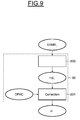
- the channel estimate processing carried out by the estimation means MEST from the digital signal of the SNC channel will make it possible to obtain an average transfer function HM of the channel which will be used for the decoding of the symbols according to the last symbol reference.
- MLB production means first elaborate in step 80 a channel transfer function H i for each SYMR reference symbol i .
- this transfer function H i is equal to the product of the received reference symbol SYMR i by the complex conjugate of the corresponding symbol transmitted by the transmitter on the transmission channel.
- this transfer function H i is in fact a complex vector having 36 complex components corresponding respectively to the 36 tones of the symbol.
- the transmission-side sampling frequency is identical to the sampling frequency of the SNC channel digital signal.
- sampling frequency of the digital signal SNC may be different from the initial digital signal developed in the transmitter.
- sampling frequency offset known to those skilled in the art under the English expression "sampling frequency offset" that must be taken into account in the estimation of the transfer functions H i .
- step 800 is determined in a manner analogous to that described in step 80 of FIG. figure 8 , basic transfer functions HB i respectively associated with reference symbols SYMR i .
- the sampling frequency offset is estimated by using, for example, two relatively long-time basic transfer functions, for example the transfer functions HB 1 and HB 13 .
- the resulting phase shift is then obtained by performing the product of the transfer function HB 1 by the complex conjugate of the transfer function HB 13 , all divided by the number of symbols.
- a phase shift correction DPHC is then obtained which is applied in a step 801 to correct the M transfer functions HB i and obtain the M transfer functions H i .
- the estimation of a transfer function from each of the symbols S1 and S2 can be carried out without difficulty since the transmitted symbols corresponding to the received symbols S1 and S2 are known.
- the figure 10 illustrates an example of estimating a transfer function H i of the channel from the symbol FCH i of the received header.
- the first step is to decode (step 100) the received symbol FCH i .
- the decoding means conventionally comprise means configured to remove from each symbol the cyclic prefix, followed by means configured to perform the FFT fast Fourier transform.
- the decoding means also comprise demapping means providing for each carrier a value of the corresponding modulation coefficient (bin). These demapping means are followed by a module configured to determine for each coefficient of modulation an indication of confidence (soft decision: "soft decision") of said value.
- This module is conventional and known per se and uses for example an algorithm of the LogMAP type.
- the decoding means also comprise deinterleaving means followed by a decoder, for example a Viterbi decoder, followed by means capable of performing a parity check.
- a decoder for example a Viterbi decoder
- the output of these means is connected to the output terminal BS of the substage ET20 which is connected to the means forming the MAC layer of the receiver.
- step 101 a re-encoding of each of these FCHD symbols i is then performed using a convolutional encoder, an interleaver and a means of mapping similar to the corresponding means ENC, INTL, MP illustrated on FIG. figure 1 for the transmitting party.
- step 80 analogous to step 80 of the figure 8 , to obtain the transfer functions H i associated with the various symbols FCH i from these received symbols FCH i and the re-encoded symbols FCHEC i .
Landscapes
- Engineering & Computer Science (AREA)
- Computer Networks & Wireless Communication (AREA)
- Signal Processing (AREA)
- Power Engineering (AREA)
- Synchronisation In Digital Transmission Systems (AREA)
- Digital Transmission Methods That Use Modulated Carrier Waves (AREA)
- Circuits Of Receivers In General (AREA)
- Cable Transmission Systems, Equalization Of Radio And Reduction Of Echo (AREA)
Abstract
On augmente le nombre de symboles à partir desquels on estime le canal temporellement invariant et on effectue une moyenne (150) des fonctions de transfert (H i ) associées à ces symboles pour utiliser ensuite cette fonction de transfert moyenne (HM) dans le décodage (151) des symboles.The number of symbols from which the time-invariant channel is estimated is increased and an average (150) of the transfer functions (H i) associated with these symbols is then used to use this mean transfer function (HM) in the decoding ( 151) symbols.
Description
Des modes de mise en oeuvre et de réalisation de l'invention concernent la transmission d'informations sur un canal de transmission, et notamment lorsque ce canal est une ligne électrique, la transmission d'informations par courant porteur en ligne (PLC : Power Line Communications), et plus particulièrement l'estimation de la fonction de transfert du canal de transmission.Embodiments and embodiments of the invention relate to the transmission of information on a transmission channel, and in particular when this channel is an electrical line, the transmission of information by power line (PLC: Power Line). Communications), and more particularly the estimation of the transfer function of the transmission channel.
Des modes de mise en oeuvre et de réalisation de l'invention sont compatibles notamment mais non exclusivement avec la norme PLC-G3 telle que définie par exemple dans la version d'avril 2015 du document de l'Alliance G3-PLC intitulé «Narrowband OFDM PLC spécifications for G3-PLC networks » à laquelle l'homme du métier pourra se référer à toutes fins utiles.Embodiments and embodiments of the invention are compatible in particular, but not exclusively, with the PLC-G3 standard as defined, for example, in the April 2015 version of the G3-PLC Alliance document entitled "Narrowband OFDM". PLC specifications for G3-PLC networks "to which the skilled person can refer for all purposes.
La technologie de courant porteur en ligne vise à transmettre des données numériques en exploitant l'infrastructure existante du réseau électrique. Elle permet notamment le relevé à distance de compteurs électriques, les échanges entre véhicules électriques et les bornes de recharge ou encore la gestion et le contrôle des réseaux d'énergie (smart grid)Powerline carrier technology aims to transmit digital data by exploiting the existing infrastructure of the power grid. It allows remote reading of electricity meters, exchanges between electric vehicles and charging stations, and the management and control of smart grids.
La technologie de courant porteur en ligne (PLC) incorpore notamment la communication par courant porteur en ligne bande étroite (Narrow band Power line Communication : N-PLC) qui est généralement définie comme une communication sur une ligne électrique opérant à des fréquences de transmission jusqu'à 500 KHz.In-line carrier technology (PLC) incorporates in particular narrow-band power line communication (N-PLC) which is generally defined as communication over a power line operating at transmission at 500 KHz.
La communication N-PLC utilise ainsi généralement les bandes de fréquences définies notamment par le comité européen de normalisation électrotechnique (CENELEC) ou par la Commission Fédérale des Communications (FCC).The N-PLC communication thus generally uses the frequency bands defined in particular by the European Committee for Electrotechnical Standardization (CENELEC) or by the Federal Communications Commission (FCC).
Ainsi si l'on considère la bande de fréquences CENELEC A (3-95 kHz), les fréquences de transmission se situent entre 35,9375 et 90,625 KHz pour la norme PLC-G3.Thus, if we consider the CENELEC A frequency band (3-95 kHz), the transmission frequencies are between 35.9375 and 90.625 KHz for the PLC-G3 standard.
Les signaux véhiculés par courant porteur en ligne et reçus par le récepteur résultent d'une combinaison de plusieurs signaux ayant emprunté au sein du canal de transmission (la ligne électrique) plusieurs chemins ou trajets de propagation ayant chacun son propre retard temporel et sa propre atténuation (le canal de transmission est un canal de transmission multi-trajets).The in-line carrier current signals received by the receiver result from a combination of several signals that have taken several paths or propagation paths within the transmission channel (the power line), each having its own time delay and its own attenuation. (the transmission channel is a multi-path transmission channel).
La performance globale d'un récepteur dépend fortement de la qualité de son estimation de canal, c'est-à-dire de l'estimation de la fonction de transfert de ce canal.The overall performance of a receiver is highly dependent on the quality of its channel estimate, i.e. the estimate of the transfer function of that channel.
Les récepteurs actuels, compatibles avec la norme PLC-G3, sont adaptés pour effectuer une estimation de canal lorsque celui-ci est linéaire et temporellement invariant (LTI : « Linear Time Invariant), en utilisant deux symboles OFDM pour estimer la fonction de transfert du canal.The current receivers, compatible with the PLC-G3 standard, are adapted to perform a channel estimation when this one is linear and temporally invariant (LTI: Linear Time Invariant), by using two OFDM symbols to estimate the transfer function of the channel.
Selon un mode de mise en oeuvre et de réalisation, il est proposé d'augmenter de plusieurs dB la performance de décodage d'un récepteur compatible notamment avec la norme PLC-G3 et connecté sur un canal du type LTI.According to one embodiment and implementation, it is proposed to increase by several dB the decoding performance of a receiver compatible in particular with the PLC-G3 standard and connected on a channel of the LTI type.
Selon un aspect, il est proposé un procédé de traitement d'un signal analogique de canal issu d'un canal de transmission (par exemple une ligne électrique, le signal étant alors véhiculé par courant porteur de ligne (PLC)) ; le signal analogique de canal véhicule des trames de symboles et le canal de transmission est considéré comme étant linéaire et temporellement invariant pour toute la durée d'au moins une trame ;
le procédé comprend une conversion analogique/numérique du signal analogique de canal de façon à obtenir un signal numérique de canal, un traitement numérique d'estimation de canal et un décodage de symboles effectués sur le signal numérique de canal ;
selon une caractéristique générale de cet aspect, le traitement numérique d'estimation de canal comprend, pour ladite au moins une trame,
une élaboration d'au moins trois fonctions de transfert dudit canal respectivement associées à au moins trois symboles de référence de ladite au moins une trame, et
un traitement de moyennage desdites fonctions de transfert obtenues de façon à obtenir une fonction de transfert moyenne ;
le décodage des symboles de ladite au moins une trame suivant lesdits symboles de référence est alors effectué en utilisant cette fonction de transfert moyenne.According to one aspect, there is provided a method of processing an analog channel signal from a transmission channel (for example a power line, the signal then being carried by line carrier current (PLC)); the channel analog signal carries symbol frames and the transmission channel is considered to be linear and temporally invariant for the duration of at least one frame;
the method comprises analog-to-digital conversion of the channel analog signal to obtain a digital channel signal, digital channel estimation processing and symbol decoding performed on the digital channel signal;
according to a general characteristic of this aspect, the digital channel estimation processing comprises, for said at least one frame,
developing at least three transfer functions of said channel respectively associated with at least three reference symbols of said at least one frame, and
an averaging process of said transfer functions obtained so as to obtain an average transfer function;
the decoding of the symbols of said at least one frame following said reference symbols is then performed using this average transfer function.
Ainsi selon cet aspect, on augmente le nombre de symboles à partir desquels on estime le canal et on effectue une moyenne des fonctions de transfert associées à ces symboles pour utiliser ensuite cette fonction de transfert moyenne dans le décodage des symboles.Thus according to this aspect, the number of symbols from which the channel is estimated is increased and an average of the transfer functions associated with these symbols is then used to use this average transfer function in the decoding of the symbols.
Ceci permet d'augmenter significativement le rapport signal sur bruit de la fonction de transfert moyenne, ce qui in fine, va conduire à une augmentation de la performance de décodage de plusieurs dB.This makes it possible to significantly increase the signal-to-noise ratio of the average transfer function, which ultimately will lead to an increase in the decoding performance of several dB.
Même si l'utilisation de trois symboles de référence apportent une amélioration par rapport aux spécifications de la norme PLC-G3, il est préférable en pratique d'utiliser un plus grand nombre de symboles de référence pour améliorer davantage les performances du décodage.Although the use of three reference symbols provides an improvement over the specifications of the PLC-G3 standard, it is preferable in practice to use a larger number of reference symbols to further improve the performance of the decoding.
Il est également avantageux d'utiliser des symboles de référence successifs.It is also advantageous to use successive reference symbols.
Ainsi selon un mode préféré de mise en oeuvre, le traitement numérique d'estimation de canal comprend, pour ladite au moins une trame une élaboration de M fonctions de transfert respectivement associées à M symboles de référence successifs de ladite au moins une trame, M étant supérieur ou égal à 3, et de préférence bien supérieur à 3, par exemple supérieur à 10.Thus, according to a preferred embodiment, the digital channel estimation processing comprises, for said at least one frame, an elaboration of M transfer functions respectively associated with M successive reference symbols of said at least one frame, M being greater than or equal to 3, and preferably much greater than 3, for example greater than 10.
Le signal analogique de canal qui va subir la conversion analogique/numérique peut être par exemple le signal analogique directement issu du canal ou bien comme c'est généralement le cas, le signal analogique délivré par un étage d'entrée analogique (comportant notamment des filtres passe-bande, des filtres passe-bas et un amplificateur) connecté sur le canal de transmission.The analog channel signal that will undergo the analog / digital conversion may be for example the analog signal directly from the channel or as is generally the case, the analog signal delivered by an analog input stage (comprising including bandpass filters, low-pass filters and an amplifier) connected to the transmission channel.
Le signal analogique de canal est par exemple conforme à la norme PLC-G3.The analog channel signal is for example compliant with the PLC-G3 standard.
Dans ce cas, le nombre M de symboles de référence peut être égal à 15 et s'étendent alors ensemble sur une durée égale à 10,42 ms (puisque chaque symbole de référence a une durée égale à 0,695 ms). Cette durée totale de 10,42 ms est légèrement supérieure à la moitié de la période du courant alternatif destiné à circuler sur la ligne électrique (soit 20 ms pour une fréquence de 50 Hz).In this case, the number M of reference symbols may be equal to 15 and then extend together over a period of time equal to 10.42 ms (since each reference symbol has a duration equal to 0.695 ms). This total duration of 10.42 ms is slightly greater than half the period of the alternating current intended to circulate on the electrical line (ie 20 ms for a frequency of 50 Hz).
De la même manière, dans les pays où la fréquence du secteur est 60 Hz, la moitié de la période du courant porteur est égale à 8,33ms et le nombre M de symboles de référence peut être pris égal à 12.Similarly, in countries where the mains frequency is 60 Hz, half of the carrier current period is 8.33 ms and the number M of reference symbols can be equal to 12.
Le canal est considéré comme temporellement invariant pour toute la durée de ladite au moins une trame.The channel is considered to be temporally invariant for the duration of said at least one frame.
Bien entendu le canal peut être temporellement invariant au cours de plusieurs trames, successives ou non, et dans ce cas on applique avantageusement les différentes étapes du procédé mentionnées ci-avant pour chacune de ces trames, le canal étant considéré, lors de la réception de chacune de ces trames, comme temporellement invariant pour toute la durée de la trame considérée.Of course the channel may be temporally invariant during several frames, successive or not, and in this case it is advantageous to apply the various process steps mentioned above for each of these frames, the channel being considered, upon receipt of each of these frames, as temporally invariant for the duration of the frame considered.
Du côté émission, le signal analogique de canal est issu d'une conversion numérique/analogique d'un signal numérique initial, et lorsque la fréquence d'échantillonnage du signal numérique de canal (en réception) est différente de la fréquence d'échantillonnage du signal numérique initial (en émission), il est préférable de tenir compte de ce décalage de fréquence d'échantillonnage (« sampling frequency offset ») pour corriger les fonctions de transfert.On the transmit side, the analog channel signal is derived from a digital-to-analog conversion of an initial digital signal, and when the sampling frequency of the digital channel signal (in reception) is different from the sampling frequency of the digital signal. initial digital signal (in transmission), it is preferable to take into account this sampling frequency offset ("sampling frequency offset") to correct the transfer functions.
Ainsi selon un mode de mise en oeuvre, le traitement numérique d'estimation de canal comprend une élaboration de M fonctions de transfert de base respectivement associées auxdits M symboles de référence de ladite trame reçue, et un traitement de correction de ces M fonctions de transfert de base avec un déphasage correspondant à ce décalage de fréquence d'échantillonnage de façon à obtenir lesdites M fonctions de transfert.Thus, according to one embodiment, the digital channel estimation processing comprises an elaboration of M basic transfer functions respectively associated with said M reference symbols of said received frame, and a correction processing of these M transfer functions. basic with a phase shift corresponding to this sampling frequency offset to obtain said M transfer functions.
Les symboles de référence de la trame reçue à partir desquels vont être déterminées les différentes fonctions de transfert, sont par exemple des symboles de la trame reçue correspondant à des symboles connus de la trame transmise et/ou sont des symboles décodables sans connaître la fonction de transfert du canal de transmission.The reference symbols of the received frame from which the different transfer functions will be determined are, for example, symbols of the received frame corresponding to known symbols of the transmitted frame and / or are decodable symbols without knowing the function of the transmitted frame. transfer of the transmission channel.
Ainsi, dans le cas de la norme PLC-G3, chaque trame reçue comporte un préambule suivi d'un en-tête suivi d'un champ utile, et les symboles de référence peuvent comprendre les symboles de l'en-tête d'une trame, qui sont décodables sans connaître la fonction de transfert de canal de transmission puisqu'ils sont codés de façon différentielle, ainsi que les deux symboles du champ utile (« payload ») de la trame qui correspondent aux deux symboles connus S1, S2 du champ utile de la trame transmise.Thus, in the case of the PLC-G3 standard, each received frame comprises a preamble followed by a header followed by a useful field, and the reference symbols may comprise the symbols of the header of a frame, which are decodable without knowing the transmission channel transfer function since they are differentially encoded, as well as the two symbols of the payload field of the frame which correspond to the two known symbols S1, S2 of the frame. useful field of the transmitted frame.
On notera donc ici que bien que la norme PLC-G3 ne prévoie comme symboles pilotes pour l'estimation de la fonction de transfert du canal, que deux symboles connus, à savoir les symboles S1 et S2, il est avantageusement prévu ici d'augmenter ce nombre de symboles pilotes en utilisant avantageusement les symboles de l'en-tête d'une trame qui sont décodables sans nécessiter de connaître la fonction de transfert du canal.It will therefore be noted here that although the PLC-G3 standard only provides as pilot symbols for estimating the transfer function of the channel, two known symbols, namely the symbols S1 and S2, it is advantageously provided here to increase this number of pilot symbols advantageously using the symbols of the header of a frame which are decodable without having to know the transfer function of the channel.
On peut alors aisément affiner l'estimation de canal et obtenir plusieurs fonctions de transfert qui seront ensuite moyennées.We can then easily refine the channel estimate and obtain several transfer functions which will then be averaged.
Cela étant il aurait été également possible d'utiliser également comme symboles de référence tout ou partie des symboles connus du préambule d'une trame afin d'augmenter encore la valeur de M et améliorer ainsi l'estimation de canal.However, it would also have been possible to also use as reference symbols all or part of the known symbols of the preamble of a frame in order to further increase the value of M and thus improve the channel estimation.
Selon un mode de mise en oeuvre, chaque élaboration d'une fonction de transfert associée à un symbole décodable reçu comprend un décodage du symbole reçu, un ré-encodage de ce symbole décodé de façon à obtenir un symbole ré-encodé et une détermination de la fonction de transfert du canal à partir dudit symbole ré-encodé et dudit symbole décodable reçu.According to an embodiment, each development of a transfer function associated with a received decodable symbol comprises a decoding of the received symbol, a re-encoding of this decoded symbol so as to obtain a re-encoded symbol and a determination of the channel transfer function from said re-encoded symbol and said received decodable symbol.
Selon un autre aspect, il est proposé un récepteur, comprenant
un étage d'entrée destiné à être connecté sur un canal de transmission et configuré pour délivrer un signal analogique de canal issu du canal de transmission, le signal analogique de canal étant destiné à véhiculer des trames de symboles, et le canal de transmission étant considéré comme étant linéaire et temporellement invariant pour toute la durée d'au moins une trame,
un étage de conversion analogique/numérique du signal analogique de canal pour délivrer un signal numérique de canal, et
un étage de traitement dudit signal numérique de canal comprenant des moyens d'estimation de canal et des moyens de décodage de symboles ;
selon une caractéristique générale de cet autre aspect, les moyens d'estimation comprennent
des moyens d'élaboration configurés pour élaborer pour ladite au moins une trame, au moins trois fonctions de transfert dudit canal respectivement associées à au moins trois symboles de référence de ladite au moins une trame, et
un bloc moyenneur configuré pour effectuer un traitement de moyennage desdites fonctions de transfert obtenues de façon à obtenir une fonction de transfert moyenne ;
les moyens de décodage sont alors configurés pour décoder les symboles de ladite au moins une trame suivant lesdits symboles de référence en utilisant cette fonction de transfert moyenne.In another aspect, there is provided a receiver, comprising
an input stage for connection on a transmission channel and configured to output an analog channel signal from the transmission channel, the channel analog signal for conveying symbol frames, and the transmission channel being considered as being linear and temporally invariant for the duration of at least one frame,
an analog / digital conversion stage of the analog channel signal for delivering a digital channel signal, and
a processing stage of said digital channel signal including channel estimation means and symbol decoding means;
according to a general characteristic of this other aspect, the estimation means comprise
developing means configured to produce for said at least one frame, at least three transfer functions of said channel respectively associated with at least three reference symbols of said at least one frame, and
an averaging block configured to perform averaging processing of said transfer functions obtained to obtain an average transfer function;
the decoding means are then configured to decode the symbols of said at least one frame according to said reference symbols using this average transfer function.
Selon un mode de réalisation, les moyens d'élaboration sont configurés pour élaborer pour ladite au moins une trame, M fonctions de transfert respectivement associées à M symboles de référence successifs de ladite au moins une trame, M étant supérieur ou égal à 3.According to one embodiment, the generating means are configured to develop for said at least one frame, M transfer functions respectively associated with M successive reference symbols of said at least one frame, M being greater than or equal to 3.
Selon un mode de réalisation, le signal analogique de canal est issu d'une conversion numérique/analogique d'un signal numérique initial, et lorsque la fréquence d'échantillonnage du signal numérique de canal est différente de la fréquence d'échantillonnage du signal numérique initial, les moyens d'élaboration sont en outre configurés pour élaborer M fonctions de transfert de base respectivement associées auxdits M symboles de référence de ladite trame reçue, et corriger ces M fonctions de transfert de base avec un déphasage correspondant à ce décalage de fréquence d'échantillonnage de façon à obtenir lesdites M fonctions de transfert.According to one embodiment, the channel analog signal is derived from a digital / analog conversion of an initial digital signal, and when the sampling frequency of the digital channel signal is different from the sampling frequency of the digital signal. initial, the means of production are further configured to develop M basic transfer functions respectively associated with said M reference symbols of said received frame, and correcting these M basic transfer functions with a phase shift corresponding to this sampling frequency offset so as to obtain said M transfer functions.
Les symboles de référence de la trame reçue peuvent correspondre à des symboles connus de la trame transmise et/ou être des symboles décodables sans connaître la fonction de transfert du canal de transmission.The reference symbols of the received frame may correspond to known symbols of the transmitted frame and / or be decodable symbols without knowing the transfer function of the transmission channel.
Selon un mode de réalisation, les moyens d'élaboration sont configurés pour élaborer une fonction de transfert associé à un symbole décodable reçu par un décodage du symbole reçu, un ré-encodage de ce symbole décodé de façon à obtenir un symbole ré-encodé et une détermination de la fonction de transfert du canal à partir dudit symbole ré-encodé et dudit symbole décodable reçu.According to one embodiment, the generating means are configured to develop a transfer function associated with a decodable symbol received by a decoding of the received symbol, a re-encoding of this decoded symbol so as to obtain a re-encoded symbol and determining the channel transfer function from said re-encoded symbol and said received decodable symbol.
Le signal peut être modulé selon une modulation OFDM.The signal can be modulated according to an OFDM modulation.
Selon un mode de réalisation le canal de transmission est une ligne électrique et le signal analogique de canal est destiné à être véhiculé par courant porteur de ligne.According to one embodiment, the transmission channel is an electrical line and the analog channel signal is intended to be carried by line carrier current.
Le signal analogique de canal peut être conforme à la norme PLC-G3.The channel analog signal may conform to the PLC-G3 standard.
Dans ce cas, chaque trame reçue comporte un préambule suivi d'un en-tête suivi d'un champ utile et lesdits symboles de référence peuvent comporter les symboles de l'entête et deux symboles du champ utile correspondant à deux symboles connus de la trame transmise.In this case, each received frame comprises a preamble followed by a header followed by a useful field and said reference symbols may comprise the symbols of the header and two symbols of the useful field corresponding to two known symbols of the frame transmitted.
D'autres avantages et caractéristiques de l'invention apparaîtront à l'examen de la description détaillée de modes de mise en oeuvre et de réalisation, nullement limitatifs, et des dessins annexés sur lesquels :
- les
figures 1 à 11 illustrent schématiquement différents modes de mise en oeuvre et de réalisation de l'invention.
- the
Figures 1 to 11 schematically illustrate different modes of implementation and embodiment of the invention.
Les modes de mise en oeuvre et de réalisation qui vont maintenant être décrits le sont dans le cadre d'une transmission d'informations par courant porteur en ligne (CPL) conforme à la norme PLC-G3, bien que l'invention ne soit pas limitée à ce type d'application.The modes of implementation and implementation that will now be described are in the context of a transmission of information by powerline carrier (CPL) in accordance with the standard PLC-G3, although the invention is not limited to this type of application.
Dans tout ce qui suit, à chaque fois qu'on citera la norme PLC-G3, on supposera que l'on considère la bande de fréquences CENELEC A (3-95 kHz).In what follows, every time we quote the PLC-G3 standard, we will assume that we consider the CENELEC A frequency band (3-95 kHz).
On se réfère maintenant à la
La chaîne de transmission comprend par exemple un encodeur ENC, par exemple un encodeur convolutionnel, recevant les données à transmettre de moyens de codage de source. Des moyens d'entrelacement INTL sont connectés à la sortie de l'encodeur et sont suivis par des moyens de « mappage » (mapping means) qui transforment les bits en symboles selon un schéma de transformation dépendant du type de modulation utilisée, par exemple une modulation de type BPSK ou plus généralement une modulation QAM.The transmission chain comprises for example an ENC encoder, for example a convolutional encoder, receiving the data to be transmitted source encoding means. INTL interleaving means are connected to the output of the encoder and are followed by means of "mapping means" which transform the bits into symbols according to a transformation scheme depending on the type of modulation used, for example a BPSK type modulation or more generally QAM modulation.
Chaque symbole contient des coefficients de modulation associés à des porteuses qui vont être modulées en conséquence. Les symboles sont délivrés en entrée de moyens de traitement MTFI destinés à effectuer une opération de transformée de Fourier inverse rapide (IFFT).Each symbol contains modulation coefficients associated with carriers that will be modulated accordingly. The symbols are delivered at the input of processing means MTFI intended to perform a fast inverse Fourier transform (IFFT) operation.
On notera ici en se référant plus particulièrement à la
Ainsi, dans la norme PLC-G3, la taille de la transformée de Fourier inverse est égale à 256 tandis que les porteuses modulées du sous-ensemble SNS sont comprises entre les rangs 23 et 58, ce qui correspond à une bande fréquentielle F1-F2 comprise entre 35,9375 et 90,625 KHz. La fréquence d'échantillonnage est ici égale à 400 KHz conduisant à un espacement entre les porteuses égal à 1,5625 KHz, ce qui rend ainsi les fréquences orthogonales (modulation OFDM).Thus, in the PLC-G3 standard, the size of the inverse Fourier transform is equal to 256 while the modulated carriers of the subset SNS lie between the
Les coefficients de modulation associés aux porteuses non utilisées sont égaux à 0.The modulation coefficients associated with the unused carriers are equal to 0.
Le signal OFDM dans le domaine temporel est généré en sortie des moyens de traitement MTFI, et des moyens MCP rajoutent à chaque symbole OFDM dans le domaine temporel, un préfixe cyclique qui est une recopie en tête du symbole OFDM d'un certain nombre d'échantillons situés à la fin de ce symbole.The OFDM signal in the time domain is generated at the output of the processing means MTFI, and means MCP add to each OFDM symbol in the time domain, a cyclic prefix which is a copy at the head of the OFDM symbol of a number of samples at the end of this symbol.
A titre d'exemple, dans la norme PLC-G3, la longueur du préfixe cyclique est de 30 échantillons pour une fréquence d'échantillonnage de 400 KHz.By way of example, in the PLC-G3 standard, the length of the cyclic prefix is 30 samples for a sampling frequency of 400 KHz.
Le signal est ensuite converti dans un convertisseur numérique/analogique CNA puis traité dans un étage ETA, communément désigné par l'homme du métier sous le vocable « Analog Front End », où il subit notamment une amplification de puissance, avant d'être transmis sur la ligne électrique LE.The signal is then converted into a digital-to-analog converter CNA then processed in an ETA stage, commonly designated by those skilled in the art under the term "Analog Front End", where it undergoes in particular a power amplification, before being transmitted on the electric line LE.
En réception, on voit, en se référant plus particulièrement à la
Cet étage d'entrée analogique ET1 comporte de façon classique un filtre passe bande BPF, un filtre passe bas LPF, ainsi que des moyens d'amplification AMP. La sortie de l'étage ET1 est connectée à un étage de conversion analogique/numérique CAN dont la sortie est connectée à l'entrée de moyens ou étage de traitement ET2.This analog input stage ET1 conventionally comprises a bandpass filter BPF, a low pass filter LPF, and amplification means AMP. The output of the stage ET1 is connected to an analog / digital conversion stage CAN whose output is connected to the input of means or processing stage ET2.
L'étage de traitement ET2 comporte ici des moyens de contrôle automatiques de gain AGC permettant de contrôler la valeur du gain des moyens d'amplification AMP de l'étage ET1.The processing stage ET2 here comprises automatic gain control means AGC making it possible to control the value of the gain of the amplification means AMP of the stage ET1.
Le signal SAC délivré en sortie de l'étage analogique ET1 et en entrée de l'étage de conversion analogique/numérique CAN désigne un signal analogique de canal issu du canal de transmission (ligne électrique) LE.The signal SAC delivered at the output of the analog stage ET1 and at the input of the analog / digital conversion stage CAN designates an analog channel signal coming from the transmission channel (electrical line) LE.
L'étage de traitement ET2 comporte également un filtre passe bas LPF2 suivi, bien que cela ne soit pas indispensable, de moyens de sous-échantillonnage MSCH. La fréquence d'échantillonnage du signal en amont des moyens MSCH est notée Fs tandis que la fréquence d'échantillonnage du signal en sortie des moyens MSCH est notée Fss.The ET2 processing stage also comprises a LPF2 low pass filter followed, although this is not essential, MSCH sub-sampling means. The sampling frequency of the signal upstream of the MSCH means is noted Fs while the sample rate of the output signal of the MSCH means is noted Fss.
Le signal SNC en sortie des moyens MSCH désigne alors ici un signal numérique de canal qui est issu de la conversion analogique/numérique du signal analogique de canal SAC et sur lequel vont être appliqués notamment un traitement de synchronisation, une estimation de canal et des décodages de symboles comme on va le voir plus en détail ci-après.The SNC signal at the output of the MSCH means here a digital channel signal which is derived from the analog / digital conversion of the analog signal SAC channel and on which will be applied in particular a synchronization processing, a channel estimation and decoding symbols as will be seen in more detail below.
L'estimation de canal est effectuée une fois la synchronisation acquise.Channel estimation is performed once the synchronization is acquired.
La fréquence Fc désigne la fréquence de calcul à laquelle vont être effectués les différents traitements.The frequency Fc designates the calculation frequency at which the different treatments will be performed.
Dans la norme PLC-G3 par exemple, la fréquence d'échantillonnage Fs spécifiée est de 400 KHz pour une taille de FFT de 256.In the PLC-G3 standard for example, the specified sampling frequency Fs is 400 KHz for an FFT size of 256.
Bien qu'il eût été possible d'effectuer toutes les opérations de ces différents traitements à une fréquence de calcul Fc égale à la fréquence d'échantillonnage Fs de 400 KHz, le fait de sous-échantillonner le signal à une fréquence Fss inférieure à Fs et d'effectuer toutes les opérations à la fréquence de calcul Fc égale à Fss permet de réduire la complexité d'implémentation de l'étage de traitement et permet également d'effectuer un traitement de transformée de Fourier rapide directe (FFT) ayant une taille réduite par rapport à la taille spécifiée de 256.Although it would have been possible to carry out all the operations of these different processes at a calculation frequency Fc equal to the sampling frequency Fs of 400 KHz, the subsample of the signal at a frequency Fss lower than Fs and performing all the operations at the calculation frequency Fc equal to Fss makes it possible to reduce the implementation complexity of the processing stage and also makes it possible to carry out a direct fast Fourier transform (FFT) processing having a size reduced compared to the specified size of 256.
Avant de revenir plus en détail sur les différents moyens qui sont incorporés dans l'étage de traitement ET2, on se réfère maintenant plus particulièrement à la
La trame reçue TRM comprend un préambule PRM comportant ici huit symboles connus SYNCP suivis d'un symbole de phase opposée SYNCM lui-même suivi d'un demi-symbole SYNCM.The received frame TRM comprises a preamble PRM comprising here eight known symbols SYNCP followed by an opposite phase symbol SYNCM itself followed by a half symbol SYNCM.
La trame TRM comporte ensuite un en-tête (header) HD suivi d'un champ utile PLD contenant des symboles de données utiles à décoder et plus connu par l'homme du métier sous la dénomination anglosaxonne de « payload ».The TRM frame then comprises a header (header) HD followed by a useful field PLD containing symbols of data useful to decode and more known by the skilled person under the Anglo-Saxon name of "payload".
Les symboles de l'en-tête HD contiennent notamment des informations de contrôle pour le décodage des données du champ PLD ainsi que le nombre d'octets à décoder dans le champ PLD.The symbols of the header HD contain in particular control information for the decoding of the data of the PLD field as well as the number of bytes to be decoded in the PLD field.
Le préambule PRM de la trame TRM permet au récepteur de se synchroniser c'est-à-dire d'obtenir une indication IND1 permettant de retrouver la structure de la trame afin de pouvoir repérer le début de l'en-tête HD.The PRM preamble of the TRM frame allows the receiver to synchronize, that is to say to obtain an indication IND1 to find the structure of the frame in order to locate the beginning of the header HD.
Le canal de transmission est un canal linéaire c'est-à-dire qu'il se comporte comme un filtre linéaire.The transmission channel is a linear channel that is to say that it behaves like a linear filter.
On considère ici en outre que pour une trame considérée le canal est linéaire temporellement invariant (LTI) pour toute la trame. En d'autres termes les caractéristiques de sa fonction de transfert sont invariantes tout au long de la trame.It is further considered here that for a frame considered the channel is linear temporally invariant (LTI) for the entire frame. In other words, the characteristics of its transfer function are invariant throughout the frame.
Dans certaines applications pour lesquelles l'environnement électrique du canal est connu (en étant par exemple exempt d'objets connectés sur une ligne électrique dont l'impédance globale n'est pas prédominée par un ou des objets dont les caractéristiques électriques génèrent une impédance cyclo-stationnaire tels que des lampes halogènes et/ou des redresseurs de tension), le canal de transmission peut être considéré de facto comme temporellement invariant au cours des trames reçues.In certain applications for which the electrical environment of the channel is known (for example by being free of objects connected on a power line whose overall impedance is not predominated by one or more objects whose electrical characteristics generate a cyclic impedance stationary such as halogen lamps and / or voltage rectifiers), the transmission channel can be considered de facto as temporally invariant during the frames received.
Dans d'autres applications, la connaissance de l'état temporellement invariant du canal au cours de la trame considérée peut résulter par exemple d'une détection préalable de l'état du canal, en particulier mais non limitativement celle décrite dans la demande de brevet français au nom de la Demanderesse, ayant pour titre « Procécé de traitement d'un signal issu d'un canal de transmission, en particulier un signal véhiculé par courant porteur en ligne, et notamment l'estimation du canal, et récepteur correspondant », et déposée le même jour que la présente demande de brevet.In other applications, knowledge of the temporally invariant state of the channel during the frame in question may result, for example, from a prior detection of the state of the channel, in particular, but not exclusively, that described in the patent application. French patent in the name of the Applicant, having the title " Process of processing a signal from a transmission channel, in particular a carrier current signal in line, and in particular the estimation of the channel, and corresponding receiver", and filed on the same day as this patent application.
Si l'on se réfère maintenant de nouveau à la
Parmi ces différents moyens, on trouve de façon classique, des moyens de synchronisation MSYNC permettant au récepteur de se synchroniser c'est-à-dire d'obtenir ladite indication IND1 permettant de retrouver la structure de la trame afin de pouvoir repérer le début de l'en-tête HD.Among these various means, there is conventionally, MSYNC synchronization means allowing the receiver to synchronize, that is to say to obtain said indication IND1 to find the structure of the frame in order to locate the beginning of the HD header.
Ces moyens de synchronisation peuvent être de structure classique et connue en soi ou bien, en variante, ceux incorporant les moyens de filtrage décrits dans la demande de brevet
Parmi les autres moyens incorporés dans le sous-étage 20, on trouve des moyens d'estimation de canal MEST comprenantAmong the other means incorporated in the sub-stage 20, there are MEST channel estimation means comprising
des moyens d'élaboration MLB configurés, comme on le verra plus en détails ci-après, pour élaborer pour la trame considérée, plusieurs fonctions de transfert du canal respectivement associées à plusieurs symboles de référence de ladite trame, et
un bloc moyenneur MMY configuré pour effectuer un traitement de moyennage desdites fonctions de transfert obtenues de façon à obtenir une fonction de transfert moyenne.MLB generating means configured, as will be seen in more detail below, to develop for the frame in question, several transfer functions of the channel respectively associated with several reference symbols of said frame, and
an MMY averaging block configured to carry out averaging processing of said transfer functions obtained so as to obtain an average transfer function.
Des moyens de décodage MDCD de structure classique et connue en soi, sont alors configurés pour décoder les symboles de ladite trame suivant lesdits symboles de référence en utilisant cette fonction de transfert moyenne.MDCD decoding means of conventional structure and known per se, are then configured to decode the symbols of said frame following said reference symbols using this average transfer function.
Si l'on se réfère maintenant plus particulièrement à la
La trame TRM comporte par ailleurs au début du champ utile PLD, deux symboles correspondant à deux symboles transmis connus S1, S2. Cela étant à des fins de simplification on désignera également par S1 et S2 ces deux symboles reçus.The TRM frame also comprises at the beginning of the useful field PLD, two symbols corresponding to two known transmitted symbols. S1, S2. For the sake of simplification, these two received symbols will also be designated S1 and S2.
Les treize symboles FCHi et les deux symboles S1 et S2 forment ici M symboles de référence SYMRi (M est égal à 15 dans cet exemple).The thirteen symbols FCH i and the two symbols S1 and S2 here form M reference symbols SYMR i (M is equal to 15 in this example).
Ces symboles de référence vont être utilisés pour élaborer M fonctions de transfert qui seront ensuite moyennées pour obtenir la fonction de transfert moyenne mentionnée ci-avant.These reference symbols will be used to develop M transfer functions which will then be averaged to obtain the average transfer function mentioned above.
Sur la
Ainsi, pour un courant et une tension alternatifs à 50 Hz, PS/2 est égale à 10 ms.Thus, for AC current and voltage at 50 Hz, PS / 2 is 10 ms.
Puisque chaque symbole de référence SYMRi a dans la norme PLC-G3, une durée égale à 0,695 ms, l'ensemble des 15 symboles de référence SYMR1-SYMR15 s'étendent temporellement sur une durée totale D égale à 10,42 ms qui est dans l'exemple particulier décrit ici, légèrement supérieure à PS/2.Since each SYMR reference symbol i has in the PLC-G3 standard, a duration equal to 0.695 ms, all 15 reference symbols SYMR 1 -SYMR 15 extend temporally over a total duration D equal to 10.42 ms. which is in the particular example described here, slightly higher than PS / 2.
En d'autres termes, dans le cas présent, la moitié de la période du signal porteur n'est pas un multiple entier de la durée d'un symbole de référence et elle est comprise entre 14 fois 0,695ms et 15 fois 0,695ms.In other words, in the present case, half of the carrier signal period is not an integer multiple of the duration of a reference symbol and is between 14 times 0.695ms and 15 times 0.695ms.
Cela étant le nombre M n'est pas lié à PS/2 et pourrait être éventuellement supérieur à 15 dans le cas où d'autre symboles de référence pourraient être utilisés comme par exemple certains au moins des symboles du préambule de la trame.This being the number M is not related to PS / 2 and could possibly be greater than 15 in the case where other reference symbols could be used, for example at least some of the symbols of the preamble of the frame.
On va maintenant décrire plus en détail la phase d'estimation du canal en se référant plus particulièrement aux
Cette phase d'estimation est effectuée ici à chaque réception de trame pour laquelle le canal est temporellement invariant, et l'on va maintenant décrire les traitements effectués au cours de l'une de ces trames.This estimation phase is carried out here at each frame reception for which the channel is temporally invariant, and one goes now describe the treatments performed during one of these frames.
Comme illustré sur la
A cet égard, comme illustré sur la
Plus précisément, cette fonction de transfert Hi est égale au produit du symbole de référence reçu SYMRi par le conjugué complexe du symbole correspondant transmis par l'émetteur sur le canal de transmission. Dans le cas présent, conforme à la norme PLC-G3, cette fonction de transfert Hi est en fait un vecteur complexe ayant 36 composantes complexes correspondant respectivement aux 36 tons du symbole.More precisely, this transfer function H i is equal to the product of the received reference symbol SYMR i by the complex conjugate of the corresponding symbol transmitted by the transmitter on the transmission channel. In the present case, according to the PLC-G3 standard, this transfer function H i is in fact a complex vector having 36 complex components corresponding respectively to the 36 tones of the symbol.
A l'issue de l'étape 80, on obtient donc une séquence initiale de M (=15) fonctions de transfert H1-H15 associées respectivement aux M (=15) symboles de référence SYMR1-SYMR15.At the end of
Dans le mode de mise en oeuvre qui vient d'être décrit, on a supposé que la fréquence d'échantillonnage côté émission était identique à la fréquence d'échantillonnage du signal numérique de canal SNC.In the embodiment that has just been described, it has been assumed that the transmission-side sampling frequency is identical to the sampling frequency of the SNC channel digital signal.
Cela étant, la fréquence d'échantillonnage du signal numérique SNC peut être différente du signal numérique initial élaboré dans l'émetteur.However, the sampling frequency of the digital signal SNC may be different from the initial digital signal developed in the transmitter.
Dans ce cas, il résulte un décalage de fréquence d'échantillonnage connu par l'homme du métier sous l'expression anglosaxonne « sampling frequency offset » qu'il faut prendre en compte dans l'estimation des fonctions de transfert Hi.In this case, it results in a sampling frequency offset known to those skilled in the art under the English expression "sampling frequency offset" that must be taken into account in the estimation of the transfer functions H i .
Ceci est illustré schématiquement sur la
Plus précisément, on détermine, dans l'étape 800, d'une façon analogue à ce qui a été décrit dans l'étape 80 de la
Puis, on estime le décalage de fréquence (« sampling frequency offset ») en utilisant par exemple deux fonctions de transfert de base relativement temporellement éloignées, par exemple les fonctions de transfert HB1 et HB13.Then, the sampling frequency offset is estimated by using, for example, two relatively long-time basic transfer functions, for example the transfer functions HB 1 and HB 13 .
Le déphasage qui en résulte est alors obtenu en effectuant le produit de la fonction de transfert HB1 par le conjugué complexe de la fonction de transfert HB13, le tout divisé par le nombre de symboles.The resulting phase shift is then obtained by performing the product of the transfer function HB 1 by the complex conjugate of the transfer function HB 13 , all divided by the number of symbols.
On obtient alors une correction de déphasage DPHC qui est appliquée dans une étape 801 pour corriger les M fonctions de transfert HBi et obtenir les M fonctions de transfert Hi.A phase shift correction DPHC is then obtained which is applied in a
L'estimation d'une fonction de transfert à partir de chacun des symboles S1 et S2 peut s'effectuer sans difficulté puisque les symboles transmis correspondant aux symboles S1 et S2 reçus sont connus.The estimation of a transfer function from each of the symbols S1 and S2 can be carried out without difficulty since the transmitted symbols corresponding to the received symbols S1 and S2 are known.
Par contre, ce n'est pas le cas pour les symboles de référence de l'en-tête c'est-à-dire les symboles FCHi.On the other hand, this is not the case for the reference symbols of the header, that is to say the symbols FCH i .
Néanmoins, comme indiqué ci-avant, ces symboles FCHi ont été codés à l'émission de façon différentielle et particulièrement robuste. Leur décodage ne nécessite donc pas la connaissance de la fonction de transfert du canal.Nevertheless, as indicated above, these symbols FCH i have been encoded in the transmission in a differential and particularly robust manner. Their decoding does not require knowledge of the transfer function of the channel.
La
On procède tout d'abord au décodage (étape 100) du symbole reçu FCHi.The first step is to decode (step 100) the received symbol FCH i .
A cet égard, les moyens de décodage comportent classiquement des moyens configurés pour retirer de chaque symbole le préfixe cyclique, suivis de moyens configurés pour effectuer la transformée de Fourier rapide directe FFT.In this regard, the decoding means conventionally comprise means configured to remove from each symbol the cyclic prefix, followed by means configured to perform the FFT fast Fourier transform.
Les moyens de décodage comportent également des moyens de démappage (demapping means) fournissant pour chaque porteuse une valeur du coefficient de modulation correspondant (bin). Ces moyens de démappage sont suivis d'un module configuré pour déterminer pour chaque coefficient de modulation une indication de confiance (décision douce : « soft décision ») de ladite valeur. Ce module est classique et connu en soi et utilise par exemple un algorithme du type LogMAP.The decoding means also comprise demapping means providing for each carrier a value of the corresponding modulation coefficient (bin). These demapping means are followed by a module configured to determine for each coefficient of modulation an indication of confidence (soft decision: "soft decision") of said value. This module is conventional and known per se and uses for example an algorithm of the LogMAP type.
Les moyens de décodage comportent également des moyens de désentrelacement suivis d'un décodeur, par exemple un décodeur de type Viterbi, suivi de moyens aptes à effectuer un contrôle de parité. La sortie de ces moyens est connectée à la borne de sortie BS du sous-étage ET20 qui est connectée aux moyens formant la couche MAC du récepteur.The decoding means also comprise deinterleaving means followed by a decoder, for example a Viterbi decoder, followed by means capable of performing a parity check. The output of these means is connected to the output terminal BS of the substage ET20 which is connected to the means forming the MAC layer of the receiver.
Puisque les différents symboles FCHi sont référencés par rapport aux symboles précédents dans la trame, il est nécessaire de décoder tous les symboles FCHi de l'en-tête avec les moyens de décodage mentionnés ci-avant. Puis, après vérification que le contrôle de parité est correct, on peut obtenir les différents symboles décodés FCHDi.Since the different symbols FCH i are referenced with respect to the preceding symbols in the frame, it is necessary to decode all the symbols FCH i of the header with the decoding means mentioned above. Then, after verifying that the parity check is correct, the different decoded symbols FCHD i can be obtained.
On effectue alors dans l'étape 101 un réencodage de chacun de ces symboles FCHDi en utilisant un encodeur convolutionnel, un entrelaceur et un moyen de mappage analogues aux moyens correspondants ENC, INTL, MP illustrés sur la
On notera à cet égard que l'on reste dans le domaine fréquentiel.Note in this respect that we remain in the frequency domain.
On obtient alors des symboles réencodés FCHECi correspondant aux symboles transmis.We then obtain re-encoded symbols FCHEC i corresponding to the transmitted symbols.
On peut alors, dans l'étape 80 analogue à l'étape 80 de la
Au lieu d'utiliser simplement, comme mentionné dans la norme PLC-G3, les symboles S1 et S2 d'une trame pour estimer la fonction de transfert du canal, on peut, comme illustré sur la
On augmente ainsi de façon significative le rapport signal sur bruit de la fonction de transfert HM, ce qui se traduit in fine par une amélioration de plusieurs dB des performances de décodage.This significantly increases the signal-to-noise ratio of the HM transfer function, which ultimately results in an improvement of several dB decoding performance.
Claims (18)
le traitement numérique d'estimation de canal comprend, pour ladite au moins une trame, une élaboration d'au moins trois fonctions de transfert (Hi) dudit canal respectivement associées à au moins trois symboles de référence (SYMRi) de ladite au moins une trame, et un traitement de moyennage (150) desdites fonctions de transfert obtenues de façon à obtenir une fonction de transfert moyenne (HM), et
le décodage (151) des symboles de ladite au moins une trame suivant lesdits symboles de référence est effectué en utilisant cette fonction de transfert moyenne.A method of processing an analog channel signal from a transmission channel, the channel analog signal conveying frames (TRM) of symbols, and the transmission channel being considered to be linear and temporally invariant for the duration of at least one frame, the method comprising analog / digital conversion of the channel analog signal to obtain a digital channel signal, digital channel estimation processing and symbol decoding performed on the digital channel signal, characterized in that
the digital channel estimation processing comprises, for said at least one frame, an elaboration of at least three transfer functions (H i ) of said channel respectively associated with at least three reference symbols (SYMR i ) of said at least one a frame, and an averaging process (150) of said transfer functions obtained to obtain a mean transfer function (HM), and
decoding (151) of the symbols of said at least one frame following said reference symbols is performed using this average transfer function.
Applications Claiming Priority (1)
| Application Number | Priority Date | Filing Date | Title |
|---|---|---|---|
| FR1556489A FR3038801B1 (en) | 2015-07-09 | 2015-07-09 | METHOD OF ESTIMATING A TEMPORALLY INVARIANT TRANSMISSION CHANNEL AND CORRESPONDING RECEIVER |
Publications (2)
| Publication Number | Publication Date |
|---|---|
| EP3116136A1 true EP3116136A1 (en) | 2017-01-11 |
| EP3116136B1 EP3116136B1 (en) | 2020-07-08 |
Family
ID=54199857
Family Applications (1)
| Application Number | Title | Priority Date | Filing Date |
|---|---|---|---|
| EP16156142.8A Active EP3116136B1 (en) | 2015-07-09 | 2016-02-17 | Method for estimating a time-invariant transmission channel, and corresponding receiver |
Country Status (4)
| Country | Link |
|---|---|
| US (2) | US9628144B2 (en) |
| EP (1) | EP3116136B1 (en) |
| CN (2) | CN106341363B (en) |
| FR (1) | FR3038801B1 (en) |
Cited By (1)
| Publication number | Priority date | Publication date | Assignee | Title |
|---|---|---|---|---|
| CN112398772A (en) * | 2019-08-14 | 2021-02-23 | 上海高清数字科技产业有限公司 | OFDM system reception demodulation method and OFDM system receiver |
Families Citing this family (3)
| Publication number | Priority date | Publication date | Assignee | Title |
|---|---|---|---|---|
| US10523702B2 (en) * | 2015-12-23 | 2019-12-31 | Mcafee, Llc | Methods and apparatus to control network connections |
| US10285001B2 (en) * | 2016-02-26 | 2019-05-07 | Snap Inc. | Generation, curation, and presentation of media collections |
| US12021667B2 (en) * | 2019-07-03 | 2024-06-25 | Nokia Technologies Oy | Transmission system with channel estimation based on a neural network |
Citations (3)
| Publication number | Priority date | Publication date | Assignee | Title |
|---|---|---|---|---|
| FR1552588A (en) | 1967-02-13 | 1969-01-03 | ||
| JP2009089146A (en) * | 2007-10-01 | 2009-04-23 | Sharp Corp | Communication apparatus, communication system, communication method, communication program, and recording medium |
| US20130170539A1 (en) * | 2011-12-29 | 2013-07-04 | Industrial Technology Research Institute | Communication device capable of channel estimation and method thereof |
Family Cites Families (31)
| Publication number | Priority date | Publication date | Assignee | Title |
|---|---|---|---|---|
| US6314131B1 (en) * | 2000-03-24 | 2001-11-06 | Cadence Design Systems, Inc. | Method and system for channel estimation using multi-slot averaged interpolation |
| FR2820507B1 (en) * | 2001-02-07 | 2003-03-28 | Onera (Off Nat Aerospatiale) | REJECTION OF CLOTS IN A PASSIVE RADAR RECEIVER OF OFDM SIGNALS |
| US7031411B2 (en) | 2001-09-19 | 2006-04-18 | Telefonaktiebolaget L.M. Ericsson | Methods and apparatus for canceling co-channel interference in a receiving system using spatio-temporal whitening |
| US7116788B1 (en) * | 2002-01-17 | 2006-10-03 | Conexant Systems, Inc. | Efficient head related transfer function filter generation |
| CN1249942C (en) * | 2003-05-13 | 2006-04-05 | 武汉汉网高技术有限公司 | Random access method utilized in orthographic frequency division multiple access (OFDM) system |
| EP1807987A4 (en) * | 2004-10-29 | 2012-11-07 | Ericsson Telefon Ab L M | Channel estimation |
| US7937048B2 (en) * | 2005-08-01 | 2011-05-03 | National Institute Of Advanced Industrial Science And Technology | Signal transmission apparatus and signal transmission method |
| JP2007258897A (en) | 2006-03-22 | 2007-10-04 | Mitsubishi Electric Corp | Power line carrier communication apparatus, and frame |
| JP5284974B2 (en) * | 2006-12-01 | 2013-09-11 | コーニンクレッカ フィリップス エレクトロニクス エヌ ヴィ | Improving performance in time-frequency interleaved orthogonal frequency division multiplexing systems |
| US8422483B2 (en) * | 2007-03-30 | 2013-04-16 | Olympus Corporation | Method and system for channel estimation in burst mode |
| EP2353317A4 (en) * | 2008-11-13 | 2015-12-23 | Blackberry Ltd | Reduced complexity channel estimation for uplink receiver |
| US8483313B2 (en) * | 2008-11-14 | 2013-07-09 | Qualcomm Incorporated | Transmission suppression |
| US8848555B2 (en) * | 2008-11-27 | 2014-09-30 | Telefonaktiebolaget L M Ericsson (Publ) | Method and a system for management of transmission resources in digital communication systems |
| US8638745B2 (en) * | 2009-05-15 | 2014-01-28 | Telefonaktiebolaget L M Ericsson (Publ) | Reference symbol distribution method and apparatus |
| US9060222B2 (en) * | 2009-06-11 | 2015-06-16 | Sda Software Design Ahnert Gmbh | Method for determining an averaged frequency-dependent transmission function for a disturbed linear time-invariant system, evaluation device and computer program product |
| JP2012156861A (en) | 2011-01-27 | 2012-08-16 | Renesas Electronics Corp | Power line communication device and noise detection method |
| US8923653B2 (en) * | 2011-06-27 | 2014-12-30 | Yutaka Yamamoto | Super-resolution processing method and system |
| US8743974B2 (en) | 2011-08-29 | 2014-06-03 | Texas Instruments Incorporated | Adaptive modulation and coding with frame size adjustment for power line communications (PLC) |
| CN102333370B (en) * | 2011-08-31 | 2015-11-18 | 华南理工大学 | In ofdm system based on extracting/the sampling clock synchronous method of compensation mechanism |
| US8718210B2 (en) * | 2011-09-20 | 2014-05-06 | Qualcomm Incorporated | Channel impulse response estimation for wireless receiver |
| WO2013171152A1 (en) * | 2012-05-18 | 2013-11-21 | Telefonica, S.A. | A method and a system for csi reporting in lte networks according to the mobility of the user equipment |
| US20140064348A1 (en) * | 2012-09-06 | 2014-03-06 | Andrew Llc | Digital Post-Distortion Compensation in Telecommunication Systems |
| EP2893645B1 (en) | 2012-09-10 | 2018-06-13 | Sony Corporation | Device for power line communication, power line communications system, method for operating a device for power line communication and for adapting plc transmissions to noise |
| WO2014121845A1 (en) * | 2013-02-08 | 2014-08-14 | Nokia Solutions And Networks Oy | Channel estimation in wireless communications |
| US9325483B2 (en) * | 2013-03-15 | 2016-04-26 | Wi-Lan Labs, Inc. | Flexible MIMO resource allocation through cross-correlation nulling and frequency domain segmented receiver processing |
| US9537641B2 (en) | 2013-05-30 | 2017-01-03 | Qualcomm Incorporated | Channel adaptation to compensate for interference from neighbor powerline communication networks |
| CN104917587B (en) | 2014-03-13 | 2018-08-14 | 钜泉光电科技(上海)股份有限公司 | Data block interleaving and de-interweaving method in communication equipment and its device |
| CN104468432B (en) * | 2014-12-31 | 2017-09-22 | 电子科技大学 | Single-carrier frequency-domain channel estimation denoising method for acoustic in a balanced way under a kind of short wave channel |
| FR3034274B1 (en) | 2015-03-27 | 2017-03-24 | Stmicroelectronics Rousset | METHOD FOR PROCESSING AN ANALOGUE SIGNAL FROM A TRANSMISSION CHANNEL, ESPECIALLY AN ONLINE CARRIER CURRENT VEHICLE SIGNAL |
| US9838077B2 (en) | 2015-07-09 | 2017-12-05 | Stmicroelectronics (Rousset) Sas | Method for estimating a cyclostationary transmission channel, and corresponding receiver |
| FR3038800A1 (en) | 2015-07-09 | 2017-01-13 | Stmicroelectronics Rousset | METHOD FOR PROCESSING A SIGNAL FROM A TRANSMISSION CHANNEL, PARTICULARLY AN IN-LINE CARRIER CURRENT VEHICLE SIGNAL, AND ESPECIALLY CHANNEL ESTIMATION, AND CORRESPONDING RECEIVER |
-
2015
- 2015-07-09 FR FR1556489A patent/FR3038801B1/en not_active Expired - Fee Related
-
2016
- 2016-02-17 EP EP16156142.8A patent/EP3116136B1/en active Active
- 2016-02-25 CN CN201610104173.7A patent/CN106341363B/en active Active
- 2016-02-25 US US15/053,264 patent/US9628144B2/en active Active
- 2016-02-25 CN CN202010165511.4A patent/CN111371710B/en active Active
-
2017
- 2017-03-09 US US15/454,904 patent/US9866274B2/en active Active
Patent Citations (3)
| Publication number | Priority date | Publication date | Assignee | Title |
|---|---|---|---|---|
| FR1552588A (en) | 1967-02-13 | 1969-01-03 | ||
| JP2009089146A (en) * | 2007-10-01 | 2009-04-23 | Sharp Corp | Communication apparatus, communication system, communication method, communication program, and recording medium |
| US20130170539A1 (en) * | 2011-12-29 | 2013-07-04 | Industrial Technology Research Institute | Communication device capable of channel estimation and method thereof |
Non-Patent Citations (1)
| Title |
|---|
| MARIO BOGDANOVIC ET AL: "IMPROVED LEAST SQUARE CHANNEL ESTIMATION ALGORITHM FOR OFDM BASED COMMUNICATION OVER POWER LINES", THE MEDITERRANEAN JOURNAL OF COMPUTERS AND NETWORKS, 30 July 2014 (2014-07-30), pages 232 - 238, XP055314959, Retrieved from the Internet <URL:https://bib.irb.hr/datoteka/717715.Bogdanovic_MEDJCN.pdf> [retrieved on 20161028] * |
Cited By (2)
| Publication number | Priority date | Publication date | Assignee | Title |
|---|---|---|---|---|
| CN112398772A (en) * | 2019-08-14 | 2021-02-23 | 上海高清数字科技产业有限公司 | OFDM system reception demodulation method and OFDM system receiver |
| CN112398772B (en) * | 2019-08-14 | 2024-04-02 | 上海高清数字科技产业有限公司 | OFDM system receiving demodulation method and OFDM system receiver |
Also Published As
| Publication number | Publication date |
|---|---|
| CN111371710B (en) | 2022-06-17 |
| EP3116136B1 (en) | 2020-07-08 |
| US9866274B2 (en) | 2018-01-09 |
| CN106341363A (en) | 2017-01-18 |
| CN106341363B (en) | 2020-03-27 |
| FR3038801B1 (en) | 2017-07-21 |
| US9628144B2 (en) | 2017-04-18 |
| CN111371710A (en) | 2020-07-03 |
| FR3038801A1 (en) | 2017-01-13 |
| US20170012670A1 (en) | 2017-01-12 |
| US20170180005A1 (en) | 2017-06-22 |
Similar Documents
| Publication | Publication Date | Title |
|---|---|---|
| EP3073695B1 (en) | Method for processing an analog signal coming from a transmission channel, in particular a signal transmitted through powerline communication | |
| EP3116135B1 (en) | Method for processing a signal from a transmission channel, in particular a signal carried over power line, and in particular the channel estimation, and corresponding receiver | |
| EP3116136B1 (en) | Method for estimating a time-invariant transmission channel, and corresponding receiver | |
| EP0709980B1 (en) | Frequency synchronisation for OFDM system | |
| EP1878185B1 (en) | Method for the coding of an OFDM/OQAM signal using symbols with complex values, and corresponding signal, devices and computer programs | |
| EP0580216A1 (en) | System and receiver for orthogonal frequency division multiplexed signals provided with a frequency synchronisation circuit | |
| FR2679085A1 (en) | SYSTEM AND METHOD FOR CALCULATING THE CHANNEL GAIN AND THE NOISE VARIANCE OF A COMMUNICATION CHANNEL. | |
| EP0608024A1 (en) | Transmissionsystem with clock recovery | |
| FR3038184A1 (en) | MULTI-SERVICE TRANSMISSION METHOD WITH SELECTION OF MULTI-CARRIER MODULATION BASED ON SERVICE | |
| EP2327190B1 (en) | Method for the blind estimation of OFDM modulation parameters according to a maximum likelihood criterion | |
| EP3116137B1 (en) | Method for estimating a cyclostationary transmission channel, and corresponding receiver | |
| FR2885471A1 (en) | METHOD FOR ITERATIVE DECODING OF OFDM / OQAM SIGNAL USING COMPLEX VALUE SYMBOLS, CORRESPONDING COMPUTER DEVICE AND PROGRAM | |
| EP2963883B1 (en) | Method for blind phase tracking for fbmc receiver | |
| WO2019012227A1 (en) | Transmission and reception of an ofdm signal on an electrical two-wire transmission channel of an aircraft | |
| EP3780529B1 (en) | Device and method for communications signalling through a fragmented spectrum | |
| FR3093257A1 (en) | ZADOFF-CHU SEQUENCE MODULATION METHOD AND DEVICE | |
| EP2481181B1 (en) | Method for reducing interferences between a first carrier current signal transmitted between modems of a power grid and a second signal transmitted between modems of another grid | |
| FR2988242A1 (en) | METHOD OF BLINDLY ESTIMATING A UPLINK WCDMA EMBROIDING CODE | |
| EP3840233A1 (en) | Circuit for detecting an enclosure and receiver including said circuit | |
| FR2890805A1 (en) | MODULATION METHOD WITH INSERTION OF SEMI-PILOT SYMBOLS | |
| EP2093889B1 (en) | Method for processing a first and second signal superimposed within an incident aggregate signal and corresponding device. | |
| WO2009000995A1 (en) | Method for receiving a frequency multiplexed transmitted signal | |
| FR2851383A1 (en) | Wireless data transmitting process for universal mobile telecommunication system, involves estimating response of transmission channel of data transmission signal by taking into account simple carrier pilot signal | |
| FR2916921A1 (en) | OFDM SIGNAL CHARACTERISTICS ESTIMATE METHOD | |
| FR2805690A1 (en) | METHOD FOR ESTIMATING RADIO FREQUENCY DIFFERENCE, AND RADIO COMMUNICATION RECEIVER USING THE METHOD |
Legal Events
| Date | Code | Title | Description |
|---|---|---|---|
| PUAI | Public reference made under article 153(3) epc to a published international application that has entered the european phase |
Free format text: ORIGINAL CODE: 0009012 |
|
| STAA | Information on the status of an ep patent application or granted ep patent |
Free format text: STATUS: REQUEST FOR EXAMINATION WAS MADE |
|
| 17P | Request for examination filed |
Effective date: 20160217 |
|
| AK | Designated contracting states |
Kind code of ref document: A1 Designated state(s): AL AT BE BG CH CY CZ DE DK EE ES FI FR GB GR HR HU IE IS IT LI LT LU LV MC MK MT NL NO PL PT RO RS SE SI SK SM TR |
|
| AX | Request for extension of the european patent |
Extension state: BA ME |
|
| GRAP | Despatch of communication of intention to grant a patent |
Free format text: ORIGINAL CODE: EPIDOSNIGR1 |
|
| STAA | Information on the status of an ep patent application or granted ep patent |
Free format text: STATUS: GRANT OF PATENT IS INTENDED |
|
| INTG | Intention to grant announced |
Effective date: 20200207 |
|
| GRAS | Grant fee paid |
Free format text: ORIGINAL CODE: EPIDOSNIGR3 |
|
| GRAA | (expected) grant |
Free format text: ORIGINAL CODE: 0009210 |
|
| STAA | Information on the status of an ep patent application or granted ep patent |
Free format text: STATUS: THE PATENT HAS BEEN GRANTED |
|
| AK | Designated contracting states |
Kind code of ref document: B1 Designated state(s): AL AT BE BG CH CY CZ DE DK EE ES FI FR GB GR HR HU IE IS IT LI LT LU LV MC MK MT NL NO PL PT RO RS SE SI SK SM TR |
|
| REG | Reference to a national code |
Ref country code: AT Ref legal event code: REF Ref document number: 1289586 Country of ref document: AT Kind code of ref document: T Effective date: 20200715 Ref country code: CH Ref legal event code: EP |
|
| REG | Reference to a national code |
Ref country code: DE Ref legal event code: R096 Ref document number: 602016039377 Country of ref document: DE |
|
| REG | Reference to a national code |
Ref country code: IE Ref legal event code: FG4D Free format text: LANGUAGE OF EP DOCUMENT: FRENCH |
|
| REG | Reference to a national code |
Ref country code: LT Ref legal event code: MG4D |
|
| REG | Reference to a national code |
Ref country code: AT Ref legal event code: MK05 Ref document number: 1289586 Country of ref document: AT Kind code of ref document: T Effective date: 20200708 |
|
| REG | Reference to a national code |
Ref country code: NL Ref legal event code: MP Effective date: 20200708 |
|
| PG25 | Lapsed in a contracting state [announced via postgrant information from national office to epo] |
Ref country code: FI Free format text: LAPSE BECAUSE OF FAILURE TO SUBMIT A TRANSLATION OF THE DESCRIPTION OR TO PAY THE FEE WITHIN THE PRESCRIBED TIME-LIMIT Effective date: 20200708 Ref country code: GR Free format text: LAPSE BECAUSE OF FAILURE TO SUBMIT A TRANSLATION OF THE DESCRIPTION OR TO PAY THE FEE WITHIN THE PRESCRIBED TIME-LIMIT Effective date: 20201009 Ref country code: HR Free format text: LAPSE BECAUSE OF FAILURE TO SUBMIT A TRANSLATION OF THE DESCRIPTION OR TO PAY THE FEE WITHIN THE PRESCRIBED TIME-LIMIT Effective date: 20200708 Ref country code: NO Free format text: LAPSE BECAUSE OF FAILURE TO SUBMIT A TRANSLATION OF THE DESCRIPTION OR TO PAY THE FEE WITHIN THE PRESCRIBED TIME-LIMIT Effective date: 20201008 Ref country code: SE Free format text: LAPSE BECAUSE OF FAILURE TO SUBMIT A TRANSLATION OF THE DESCRIPTION OR TO PAY THE FEE WITHIN THE PRESCRIBED TIME-LIMIT Effective date: 20200708 Ref country code: PT Free format text: LAPSE BECAUSE OF FAILURE TO SUBMIT A TRANSLATION OF THE DESCRIPTION OR TO PAY THE FEE WITHIN THE PRESCRIBED TIME-LIMIT Effective date: 20201109 Ref country code: BG Free format text: LAPSE BECAUSE OF FAILURE TO SUBMIT A TRANSLATION OF THE DESCRIPTION OR TO PAY THE FEE WITHIN THE PRESCRIBED TIME-LIMIT Effective date: 20201008 Ref country code: AT Free format text: LAPSE BECAUSE OF FAILURE TO SUBMIT A TRANSLATION OF THE DESCRIPTION OR TO PAY THE FEE WITHIN THE PRESCRIBED TIME-LIMIT Effective date: 20200708 Ref country code: LT Free format text: LAPSE BECAUSE OF FAILURE TO SUBMIT A TRANSLATION OF THE DESCRIPTION OR TO PAY THE FEE WITHIN THE PRESCRIBED TIME-LIMIT Effective date: 20200708 Ref country code: ES Free format text: LAPSE BECAUSE OF FAILURE TO SUBMIT A TRANSLATION OF THE DESCRIPTION OR TO PAY THE FEE WITHIN THE PRESCRIBED TIME-LIMIT Effective date: 20200708 |
|
| PG25 | Lapsed in a contracting state [announced via postgrant information from national office to epo] |
Ref country code: IS Free format text: LAPSE BECAUSE OF FAILURE TO SUBMIT A TRANSLATION OF THE DESCRIPTION OR TO PAY THE FEE WITHIN THE PRESCRIBED TIME-LIMIT Effective date: 20201108 Ref country code: PL Free format text: LAPSE BECAUSE OF FAILURE TO SUBMIT A TRANSLATION OF THE DESCRIPTION OR TO PAY THE FEE WITHIN THE PRESCRIBED TIME-LIMIT Effective date: 20200708 Ref country code: LV Free format text: LAPSE BECAUSE OF FAILURE TO SUBMIT A TRANSLATION OF THE DESCRIPTION OR TO PAY THE FEE WITHIN THE PRESCRIBED TIME-LIMIT Effective date: 20200708 Ref country code: RS Free format text: LAPSE BECAUSE OF FAILURE TO SUBMIT A TRANSLATION OF THE DESCRIPTION OR TO PAY THE FEE WITHIN THE PRESCRIBED TIME-LIMIT Effective date: 20200708 |
|
| PG25 | Lapsed in a contracting state [announced via postgrant information from national office to epo] |
Ref country code: NL Free format text: LAPSE BECAUSE OF FAILURE TO SUBMIT A TRANSLATION OF THE DESCRIPTION OR TO PAY THE FEE WITHIN THE PRESCRIBED TIME-LIMIT Effective date: 20200708 |
|
| REG | Reference to a national code |
Ref country code: DE Ref legal event code: R097 Ref document number: 602016039377 Country of ref document: DE |
|
| PG25 | Lapsed in a contracting state [announced via postgrant information from national office to epo] |
Ref country code: SM Free format text: LAPSE BECAUSE OF FAILURE TO SUBMIT A TRANSLATION OF THE DESCRIPTION OR TO PAY THE FEE WITHIN THE PRESCRIBED TIME-LIMIT Effective date: 20200708 Ref country code: RO Free format text: LAPSE BECAUSE OF FAILURE TO SUBMIT A TRANSLATION OF THE DESCRIPTION OR TO PAY THE FEE WITHIN THE PRESCRIBED TIME-LIMIT Effective date: 20200708 Ref country code: EE Free format text: LAPSE BECAUSE OF FAILURE TO SUBMIT A TRANSLATION OF THE DESCRIPTION OR TO PAY THE FEE WITHIN THE PRESCRIBED TIME-LIMIT Effective date: 20200708 Ref country code: CZ Free format text: LAPSE BECAUSE OF FAILURE TO SUBMIT A TRANSLATION OF THE DESCRIPTION OR TO PAY THE FEE WITHIN THE PRESCRIBED TIME-LIMIT Effective date: 20200708 Ref country code: DK Free format text: LAPSE BECAUSE OF FAILURE TO SUBMIT A TRANSLATION OF THE DESCRIPTION OR TO PAY THE FEE WITHIN THE PRESCRIBED TIME-LIMIT Effective date: 20200708 Ref country code: IT Free format text: LAPSE BECAUSE OF FAILURE TO SUBMIT A TRANSLATION OF THE DESCRIPTION OR TO PAY THE FEE WITHIN THE PRESCRIBED TIME-LIMIT Effective date: 20200708 |
|
| PLBE | No opposition filed within time limit |
Free format text: ORIGINAL CODE: 0009261 |
|
| STAA | Information on the status of an ep patent application or granted ep patent |
Free format text: STATUS: NO OPPOSITION FILED WITHIN TIME LIMIT |
|
| PG25 | Lapsed in a contracting state [announced via postgrant information from national office to epo] |
Ref country code: AL Free format text: LAPSE BECAUSE OF FAILURE TO SUBMIT A TRANSLATION OF THE DESCRIPTION OR TO PAY THE FEE WITHIN THE PRESCRIBED TIME-LIMIT Effective date: 20200708 |
|
| 26N | No opposition filed |
Effective date: 20210409 |
|
| PG25 | Lapsed in a contracting state [announced via postgrant information from national office to epo] |
Ref country code: SK Free format text: LAPSE BECAUSE OF FAILURE TO SUBMIT A TRANSLATION OF THE DESCRIPTION OR TO PAY THE FEE WITHIN THE PRESCRIBED TIME-LIMIT Effective date: 20200708 |
|
| PG25 | Lapsed in a contracting state [announced via postgrant information from national office to epo] |
Ref country code: SI Free format text: LAPSE BECAUSE OF FAILURE TO SUBMIT A TRANSLATION OF THE DESCRIPTION OR TO PAY THE FEE WITHIN THE PRESCRIBED TIME-LIMIT Effective date: 20200708 |
|
| PG25 | Lapsed in a contracting state [announced via postgrant information from national office to epo] |
Ref country code: MC Free format text: LAPSE BECAUSE OF FAILURE TO SUBMIT A TRANSLATION OF THE DESCRIPTION OR TO PAY THE FEE WITHIN THE PRESCRIBED TIME-LIMIT Effective date: 20200708 |
|
| GBPC | Gb: european patent ceased through non-payment of renewal fee |
Effective date: 20210217 |
|
| REG | Reference to a national code |
Ref country code: BE Ref legal event code: MM Effective date: 20210228 |
|
| PG25 | Lapsed in a contracting state [announced via postgrant information from national office to epo] |
Ref country code: CH Free format text: LAPSE BECAUSE OF NON-PAYMENT OF DUE FEES Effective date: 20210228 Ref country code: LI Free format text: LAPSE BECAUSE OF NON-PAYMENT OF DUE FEES Effective date: 20210228 Ref country code: LU Free format text: LAPSE BECAUSE OF NON-PAYMENT OF DUE FEES Effective date: 20210217 |
|
| PG25 | Lapsed in a contracting state [announced via postgrant information from national office to epo] |
Ref country code: IE Free format text: LAPSE BECAUSE OF NON-PAYMENT OF DUE FEES Effective date: 20210217 Ref country code: GB Free format text: LAPSE BECAUSE OF NON-PAYMENT OF DUE FEES Effective date: 20210217 |
|
| PG25 | Lapsed in a contracting state [announced via postgrant information from national office to epo] |
Ref country code: BE Free format text: LAPSE BECAUSE OF NON-PAYMENT OF DUE FEES Effective date: 20210228 |
|
| PG25 | Lapsed in a contracting state [announced via postgrant information from national office to epo] |
Ref country code: HU Free format text: LAPSE BECAUSE OF FAILURE TO SUBMIT A TRANSLATION OF THE DESCRIPTION OR TO PAY THE FEE WITHIN THE PRESCRIBED TIME-LIMIT; INVALID AB INITIO Effective date: 20160217 |
|
| PG25 | Lapsed in a contracting state [announced via postgrant information from national office to epo] |
Ref country code: CY Free format text: LAPSE BECAUSE OF FAILURE TO SUBMIT A TRANSLATION OF THE DESCRIPTION OR TO PAY THE FEE WITHIN THE PRESCRIBED TIME-LIMIT Effective date: 20200708 |
|
| PG25 | Lapsed in a contracting state [announced via postgrant information from national office to epo] |
Ref country code: MK Free format text: LAPSE BECAUSE OF FAILURE TO SUBMIT A TRANSLATION OF THE DESCRIPTION OR TO PAY THE FEE WITHIN THE PRESCRIBED TIME-LIMIT Effective date: 20200708 |
|
| PGFP | Annual fee paid to national office [announced via postgrant information from national office to epo] |
Ref country code: DE Payment date: 20240123 Year of fee payment: 9 |
|
| PGFP | Annual fee paid to national office [announced via postgrant information from national office to epo] |
Ref country code: FR Payment date: 20240123 Year of fee payment: 9 |
|
| PG25 | Lapsed in a contracting state [announced via postgrant information from national office to epo] |
Ref country code: MT Free format text: LAPSE BECAUSE OF FAILURE TO SUBMIT A TRANSLATION OF THE DESCRIPTION OR TO PAY THE FEE WITHIN THE PRESCRIBED TIME-LIMIT Effective date: 20200708 |