EP3116104A1 - Slot insulation for electrical machines - Google Patents
Slot insulation for electrical machines Download PDFInfo
- Publication number
- EP3116104A1 EP3116104A1 EP16177924.4A EP16177924A EP3116104A1 EP 3116104 A1 EP3116104 A1 EP 3116104A1 EP 16177924 A EP16177924 A EP 16177924A EP 3116104 A1 EP3116104 A1 EP 3116104A1
- Authority
- EP
- European Patent Office
- Prior art keywords
- slot
- winding
- recited
- span portion
- electrical machine
- Prior art date
- Legal status (The legal status is an assumption and is not a legal conclusion. Google has not performed a legal analysis and makes no representation as to the accuracy of the status listed.)
- Granted
Links
Images





Classifications
-
- H—ELECTRICITY
- H02—GENERATION; CONVERSION OR DISTRIBUTION OF ELECTRIC POWER
- H02K—DYNAMO-ELECTRIC MACHINES
- H02K3/00—Details of windings
- H02K3/32—Windings characterised by the shape, form or construction of the insulation
- H02K3/34—Windings characterised by the shape, form or construction of the insulation between conductors or between conductor and core, e.g. slot insulation
- H02K3/345—Windings characterised by the shape, form or construction of the insulation between conductors or between conductor and core, e.g. slot insulation between conductor and core, e.g. slot insulation
-
- H—ELECTRICITY
- H02—GENERATION; CONVERSION OR DISTRIBUTION OF ELECTRIC POWER
- H02K—DYNAMO-ELECTRIC MACHINES
- H02K3/00—Details of windings
- H02K3/32—Windings characterised by the shape, form or construction of the insulation
- H02K3/38—Windings characterised by the shape, form or construction of the insulation around winding heads, equalising connectors, or connections thereto
-
- H—ELECTRICITY
- H02—GENERATION; CONVERSION OR DISTRIBUTION OF ELECTRIC POWER
- H02K—DYNAMO-ELECTRIC MACHINES
- H02K9/00—Arrangements for cooling or ventilating
- H02K9/22—Arrangements for cooling or ventilating by solid heat conducting material embedded in, or arranged in contact with, the stator or rotor, e.g. heat bridges
- H02K9/223—Heat bridges
-
- H—ELECTRICITY
- H02—GENERATION; CONVERSION OR DISTRIBUTION OF ELECTRIC POWER
- H02K—DYNAMO-ELECTRIC MACHINES
- H02K3/00—Details of windings
- H02K3/32—Windings characterised by the shape, form or construction of the insulation
-
- H—ELECTRICITY
- H02—GENERATION; CONVERSION OR DISTRIBUTION OF ELECTRIC POWER
- H02K—DYNAMO-ELECTRIC MACHINES
- H02K3/00—Details of windings
- H02K3/32—Windings characterised by the shape, form or construction of the insulation
- H02K3/34—Windings characterised by the shape, form or construction of the insulation between conductors or between conductor and core, e.g. slot insulation
-
- H—ELECTRICITY
- H02—GENERATION; CONVERSION OR DISTRIBUTION OF ELECTRIC POWER
- H02K—DYNAMO-ELECTRIC MACHINES
- H02K3/00—Details of windings
- H02K3/46—Fastening of windings on the stator or rotor structure
- H02K3/48—Fastening of windings on the stator or rotor structure in slots
- H02K3/487—Slot-closing devices
Definitions
- the span portion 122 can include a material different than that of the first and second slot liners 114 and 118, wherein the material of the span portion 122 has a higher thermal conductivity than that of the first and second slot liners 114 and 118 to facilitate heat removal from end windings 112, through slot span portions 122, and into arms 104 of core 102.
- Slot insulators 110 can be seated in core 102 prior to winding. In both lap wound and concentric wound configurations, the windings 106 hold slot insulators 110 in place after winding.
Landscapes
- Engineering & Computer Science (AREA)
- Power Engineering (AREA)
- Insulation, Fastening Of Motor, Generator Windings (AREA)
Description
- The present disclosure relates to electrical machines, and more particularly to slot insulation such as used in electric motors, generators and generator/motors.
- A variety of devices and methods are known in the art for supporting electrical machine end windings, and for transferring heat from end windings. For example, heat resistant papers can be used to insulate end windings from each other and/or from the core supporting the windings. One common method of cooling the end windings is air cooling, for example, where flowing air impinges on resin impregnated end windings. A typical failure mode for air cooled end windings is for the windings to fail at the location where the windings exit the slot of the core, e.g., the stator slot. These typical failures are caused by loss of insulation between the winding and the core.
- Such conventional methods and systems have generally been considered satisfactory for their intended purpose. However, there is still a need in the art for improved slot insulation for electrical machines. The present disclosure provides a solution for this need.
- An electrical machine includes a winding core with a plurality of end slots. A winding is seated in the end slots with end windings where the winding crosses from end slot to end slot. A slot insulator is seated in two of the end slots. The slot insulator includes a first slot liner seated in a first one of the two end slots with a winding slot defined therethrough in an axial direction. One of the end windings enters the first one of the end slots through the winding slot of the first slot liner. A second slot liner is seated in a second one of the two end slots with a winding slot defined therethrough in the axial direction, wherein the second slot liner is spaced apart in a lateral direction relative to the axial direction from the first slot liner by a gap. One of the end windings exits the second one of the end slots through the winding slot of the second slot liner. The slot insulator includes a span portion bridging across the gap to connect the first and second slot liners.
- The end winding can be in intimate contact with the span portion for heat removal from the end winding. The span portion can be contoured. For example, the span portion can include a curved surface that curves in a direction around an axis perpendicular to the axial direction and to the lateral direction. Each of the first and second slot liners can define a complete perimeter surrounding the respective winding slot, insulating the end winding from the winding core. The two end slots in which the slot insulator is seated can be two adjacent slots of the plurality of end slots. The first and second slot liners and the span portion can be a unitary structure including at least one of polyetherimide, PEEK, aluminum nitride based composite materials, aluminum oxide based composite materials, boron nitride based composite materials, any other suitable type ceramic based composite material, or any other suitable materials in general. It is also contemplated that the span portion can include a material different than that of the first and second slot liners, wherein the material of the span portion has a higher thermal conductivity than that of the first and second slot liners.
- The winding can be concentric wound and the end winding entering the first one of the end slots can be the same as the end winding exiting the second one of the end slots. It is also contemplated that the winding can be lap wound.
- These and other features of the systems and methods of the subject disclosure will become more readily apparent to those skilled in the art from the following detailed description of the preferred embodiments taken in conjunction with the drawings.
- So that those skilled in the art to which the subject disclosure appertains will readily understand how to make and use the devices and methods of the subject disclosure without undue experimentation, preferred embodiments thereof will be described in detail herein below with reference to certain figures, wherein:
-
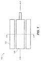
Fig. 1 is a schematic cross-sectional side elevation view of an exemplary embodiment of an electrical machine constructed in accordance with the present disclosure, showing the stator and rotor; -
Fig. 2 is a cross-sectional end elevation view of the electric machine ofFig. 1 , showing the stator core slots; -
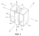
Fig. 3 is a perspective view of an exemplary embodiment of an end slot insulator constructed in accordance with the present disclosure, showing the first and second slot liners spaced apart across a gap and connected by the span portion; -
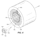
Fig. 4 is an exploded perspective view of a portion of the electrical machine ofFig. 1 , indicating the positions for seating the end slot insulators on the end slots of the stator core; -
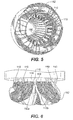
Fig. 5 is a perspective view of a portion of the electrical machine ofFig. 1 , showing the stator core, end slot insulators, and end windings; -
Fig. 6 is a perspective view of a portion of the stator core, end slot insulators, and end windings ofFig. 5 ; -
Fig. 7 is an end view of a portion of the electrical machine ofFig. 1 , showing an exemplary embodiment of the winding that is concentric wound; -
Fig. 8 is a schematic radial cross-sectional view of a portion of the stator core ofFig. 7 , showing winding passing through slot insulators on each end of the stator core; -
Fig. 9 is a schematic circumferential cross-sectional view of the stator core ofFig. 8 , showing the concentric wound winding; -
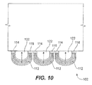
Fig. 10 is a schematic view of a portion of the electrical machine ofFig. 7 , schematically showing the heat transfer from the end windings, through the slot insulator, and into the core; -
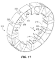
Fig. 11 is a perspective view of another exemplary embodiment of an end slot insulator constructed in accordance with the present disclosure, showing a ring of circumferentially spaced slot liners, spaced apart across respective gaps and connected by respective span portions; -
Fig. 12 is an exploded perspective view of the end slot insulator ofFig. 11 and a stator core; and -
Fig. 13 is a perspective view of the end slot insulator and stator core ofFig. 12 , showing the end slot insulator assembled onto the stator core. - Reference will now be made to the drawings wherein like reference numerals identify similar structural features or aspects of the subject disclosure. For purposes of explanation and illustration, and not limitation, a partial view of an exemplary embodiment of an electrical machine in accordance with the disclosure is shown in
Fig. 1 and is designated generally byreference character 100. Other embodiments of electrical machines in accordance with the disclosure, or aspects thereof, are provided inFigs. 2-10 , as will be described. The systems and methods described herein can be used improve electrical insulation and heat transfer for end windings for longer service life in electrical machines such as motors, generators, and electrical machines that are used as motors and generators, such as starter motor/generators for gas turbine engines. -
Electrical machine 100 includes astator 101 and arotor 108.Stator 101 includes a winding core, namelystator core 102 and winding 106, as shown inFig. 2 .Core 102 includes a plurality of end slots defined betweenadjacent core arms 104, i.e., the slots occupied bywindings 106 inFig. 2 .Winding 106 is seated in the end slots withend windings 112, labeled inFigs. 5 and 6 , protruding from each end ofcore 102 beyond the end slots, where the winding 106 crosses from end slot to end slot. - With reference to
Figs. 3 and4 , aslot insulator 110 is seated in two of the end slots.Fig. 3 shows theslot insulator 110 in isolation, which includes afirst slot liner 114 seated in a first one of the two end slots, as indicated by the corresponding dashed inFig. 4 . Awinding slot 116 is defined throughslot liner 114 in an axial direction A. One of theend windings 112, e.g., end winding 112a inFig. 6 , enters the first one of the end slots through thewinding slot 116 of the first slot liner. Asecond slot liner 118 is seated in a second one of the two end slots, as indicated by the corresponding dashed line inFig. 4 . Awinding slot 120 is defined throughslot liner 118 in the axial direction A. - With continued reference to
Fig. 3 , thesecond slot liner 118 is spaced apart in a lateral direction B relative to the axial direction A from the first slot liner by a gap G. One of theend windings 112, e.g., end winding 112b inFig. 6 , exits the second one of the end slots through thewinding slot 120 of thesecond slot liner 118. Each of the first andsecond slot liners complete perimeter 126 surrounding therespective winding slot end windings 112 from thecore 102.Slot insulators 110 are seated in each end slot ofcore 102, wherein eachslot insulator 110 is seated in two adjacent slots, as shown inFigs. 5 and 6 . Specifically, eachslot liner 114 is seated in an end slot next to therespective slot liner 118 of thesame slot insulator 110, where gap G is occupied with arespective core arm 104, as indicated inFig. 4 . -
Slot insulator 110 includes aspan portion 122 bridging across the gap G to connect the first andsecond slot liners Span portion 122 is optionally contoured. For example, as shown inFig. 3 ,span portion 122 includes acurved surface 124 that curves in a direction around an axis C perpendicular to the axial direction A and to the lateral direction B. - Winding 106 as shown in
Figs. 5 and 6 has a lap wound configuration. With reference now toFig. 7 , it is also contemplated that concentric wound winding configurations can be used. InFig. 7 ,end windings 112 are shown in a concentric wound configuration, where each end winding 112 is supported by arespective slot insulator 110 seated the end slots ofcore 102 as described above.Fig. 8 shows a radial schematic view of winding 106 with its end winding 112 supported on opposed ends ofcore 102 byrespective slot insulators 110.Fig. 9 shows the same winding 106 viewed inward along the radius ofcore 102. Theend windings 112 are in intimate contact with thespan portion 122, due to the contouredsurface 124 labeled inFig. 3 , for heat removal from each end winding 122. This heat removal is indicated schematically inFig. 10 by the large arrows. - It is contemplated that first and
second slot liners span portion 122 can be a rigid, unitary structure including any suitable material such as polyetherimide, e.g., ULTEM polymers available from SABIC of Riyadh, Saudi Arabia, polyether ether ketone (PEEK), aluminum nitride based composite materials, aluminum oxide based composite materials, boron nitride based composite materials, any other suitable type ceramic based composite material, or any other suitable materials in general. It is also contemplated that thespan portion 122 can include a material different than that of the first andsecond slot liners span portion 122 has a higher thermal conductivity than that of the first andsecond slot liners end windings 112, throughslot span portions 122, and intoarms 104 ofcore 102.Slot insulators 110 can be seated incore 102 prior to winding. In both lap wound and concentric wound configurations, thewindings 106hold slot insulators 110 in place after winding. - With reference now to
Fig. 11 , another exemplary embodiment of aslot insulator 210 is shown, which is in the form of a complete ring.Individual slot liners 214, only four of which are labeled inFig. 11 for sake of clarity, can be seated in end slots ofstator 101, as indicated inFigs. 12 and13 . A windingslot 216 is defined through eachslot liner 214 in an axial direction A. An optionalinner ring 215 is indicated with dashed lines inFig. 11 , which if included provides a complete perimeter, much likeperimeter 126 described above, in eachslot liner 214 about its respective windingslot 216. Those skilled in the art will readily appreciate thatinner ring 215 is optional inslot insulator 210, and that it is also optional to have acomplete perimeter 126 inslot insulator 110 described above, which could for example be left open on the radially inner perimeter.End windings 112, e.g., end winding 112a inFig. 6 , can pass through the windingslots 216, much as described above with respect to slotinsulator 210.Slot insulator 210 includes aspan portion 222 bridging across the gap G to connect the first and secondadjacent slot liners 214.Span portion 222 can optionally be contoured as described above. For example, as shown inFig. 11 ,span portion 222 includes aflat surface 224 that can optionally be curved instead, in a direction assurface 124 inFig. 3 . - The mechanical rigidity of
slot insulators slot insulators Slot insulators - While shown and described in the exemplary context of a stator with inward facing winding slots, those skilled in the art will readily appreciate that rotors and/or cores with outward facing winding slots can also be used without departing from the scope of this disclosure. Moreover, those skilled in the art will readily appreciate that the systems and techniques disclosed herein can be applied to any suitable type of electrical machine, including motors, generators, and electrical machines that are used as both generators and motors, such as in starter motor/generators for gas turbine engines.
- The methods and systems of the present disclosure, as described above and shown in the drawings, provide for electrical machines with superior properties including improved mechanical rigidity, electrical insulation and heat transfer for end windings. While the apparatus and methods of the subject disclosure have been shown and described with reference to preferred embodiments, those skilled in the art will readily appreciate that changes and/or modifications may be made thereto without departing from the scope of the subject disclosure.
Claims (15)
- A slot insulator (110, 210) for an electrical machine comprising:a first slot liner (114, 214) with a winding slot (116) defined therethrough in an axial direction;a second slot liner (118, 218) with a winding slot (120) defined therethrough in the axial direction, wherein the second slot liner (118, 218) is spaced apart in a lateral direction relative to the axial direction from the first slot liner (114, 214) by a gap; anda span portion (122, 222) bridging across the gap to connect the first (114, 214) and second slot liners (118, 218).
- A slot insulator as recited in claim 1, wherein the span portion (122, 222) is contoured.
- A slot insulator as recited in claim 2, wherein the span portion (112, 212) includes a curved surface (124) that curves in a direction around an axis perpendicular to the axial direction and to the lateral direction.
- A slot insulator as recited in any preceding claim, wherein each of the first (114, 214) and second slot liners (118, 218) defines a complete perimeter surrounding the respective winding slot (116, 120).
- A slot insulator as recited in any preceding claim, wherein the first (114, 214) and second slot liners (118, 218) and the span portion (122, 222) are a unitary structure including at least one of polyetherimide, PEEK, aluminum nitride based composite materials, aluminum oxide based composite materials, or boron nitride based composite materials.
- A slot insulator as recited in any preceding claim, wherein the span portion (122, 222) includes a material different than that of the first (114, 214) and second slot liners (118, 218), wherein the material of the span portion has a higher thermal conductivity than that of the first (114) and second slot liners (118, 218).
- An electrical machine comprising:a winding core (102) with a plurality of end slots;a winding seated in the end slots with end windings (112, 212) where the winding crosses from end slot to end slot; andthe slot insulator of any preceding claim seated in two of the end slots:wherein one of the end windings exits the second one of the end slots through the winding slot of the second slot liner.said first slot liner (114) seated in a first one of the two end slots, wherein one of the end windings enters the first one of the end slots through the winding slot of the first slot liner;said second slot liner (118) seated in a second one of the two end slots and,
- An electrical machine as recited in claim 7, wherein the end winding (112) is in intimate contact with the span portion for heat removal from the end winding.
- An electrical machine as recited in claim 8, wherein the span portion (122) is contoured.
- An electrical machine as recited in any of claims 7 to 9, wherein the span portion (122, 222) includes a curved surface that curves in a direction around an axis perpendicular to the axial direction and to the lateral direction.
- An electrical machine as recited in any of claims 7 to 10, wherein each of the first (114, 214) and second slot liners (118, 218) defines a complete perimeter surrounding the respective winding slot, insulating the end winding from the winding core (102).
- An electrical machine as recited in any of claims 7 to 11, wherein the two end slots in which the slot insulator is seated are two adjacent slots of the plurality of end slots.
- An electrical machine as recited in any of claims 7 to 12, wherein the first (114, 214) and second slot liners (118, 218) and the span portion (122, 222) are a unitary structure including at least one of polyetherimide, PEEK, aluminum nitride based composite materials, aluminum oxide based composite materials, or boron nitride based composite materials.
- An electrical machine as recited in any of claims 7 to 13, wherein the span portion (122, 222) includes a material different than that of the first and second slot liners, wherein the material of the span portion has a higher thermal conductivity than that of the first and second slot liners.
- An electrical machine as recited in any of claims 7 to 14,
wherein the winding is concentric wound and the end winding entering the first one of the end slots is the same as the end winding exiting the second one of the end slots; or
wherein winding is lap wound.
Applications Claiming Priority (1)
| Application Number | Priority Date | Filing Date | Title |
|---|---|---|---|
| US14/791,987 US10333364B2 (en) | 2015-07-06 | 2015-07-06 | Slot insulation for electrical machines |
Publications (2)
| Publication Number | Publication Date |
|---|---|
| EP3116104A1 true EP3116104A1 (en) | 2017-01-11 |
| EP3116104B1 EP3116104B1 (en) | 2020-06-17 |
Family
ID=56345065
Family Applications (1)
| Application Number | Title | Priority Date | Filing Date |
|---|---|---|---|
| EP16177924.4A Active EP3116104B1 (en) | 2015-07-06 | 2016-07-05 | Slot insulation for electrical machines |
Country Status (2)
| Country | Link |
|---|---|
| US (1) | US10333364B2 (en) |
| EP (1) | EP3116104B1 (en) |
Cited By (3)
| Publication number | Priority date | Publication date | Assignee | Title |
|---|---|---|---|---|
| US20160344264A1 (en) * | 2015-05-19 | 2016-11-24 | General Electric Company | Electrical machine cooling structure |
| WO2020120626A1 (en) * | 2018-12-12 | 2020-06-18 | Thyssenkrupp Ag | Isolating ring, stator and electric machine |
| DE102019203476A1 (en) * | 2019-03-14 | 2020-09-17 | Audi Ag | Stator for an electric machine |
Families Citing this family (4)
| Publication number | Priority date | Publication date | Assignee | Title |
|---|---|---|---|---|
| DE102021201666A1 (en) * | 2021-02-22 | 2022-08-25 | Siemens Aktiengesellschaft | Slot insulation system for an electric rotating machine, method of manufacturing a slot insulation system |
| DE102021105651A1 (en) | 2021-03-09 | 2022-09-15 | Dr. Ing. H.C. F. Porsche Aktiengesellschaft | High-voltage electric motor stator assembly |
| KR102908698B1 (en) * | 2021-04-15 | 2026-01-06 | 현대자동차주식회사 | Bobbin structure |
| EP4476280A1 (en) * | 2022-02-10 | 2024-12-18 | Solvay Specialty Polymers USA, LLC | Component used as an electrical insulation barrier based on a polyaryletherketone (paek) and a polyphenylsulfone (ppsu) |
Citations (4)
| Publication number | Priority date | Publication date | Assignee | Title |
|---|---|---|---|---|
| DE102007004562A1 (en) * | 2007-01-30 | 2008-07-31 | Robert Bosch Gmbh | Isolation lamella for electrical machine anchor, particularly electric motor anchor or electrical generator anchor, contains ferromagnetic material with modified plastic and powder composite material |
| DE102008033601A1 (en) * | 2008-07-17 | 2010-01-21 | Sew-Eurodrive Gmbh & Co. Kg | Electric motor, has end cap positively connected with retaining ring, and encapsulating cap positively connected with another cap lying axially opposite to former end cap, where encapsulating cap projects outwardly |
| GB2493658A (en) * | 2012-10-15 | 2013-02-13 | Protean Electric Ltd | An insulated tooth for an electric motor or generator |
| US20130207395A1 (en) * | 2012-02-13 | 2013-08-15 | Ge Aviation Systems Llc | Aircraft engine starter/generator |
Family Cites Families (18)
| Publication number | Priority date | Publication date | Assignee | Title |
|---|---|---|---|---|
| US3109947A (en) | 1959-06-26 | 1963-11-05 | Gen Electric | Cooling system for dynamoelectric machines |
| USRE28705E (en) | 1970-07-21 | 1976-02-03 | General Electric Company | Stator slot and winding arrangements |
| US6124660A (en) * | 1997-05-26 | 2000-09-26 | Denso Corporation | AC generator for vehicles |
| US6509665B1 (en) | 1999-10-25 | 2003-01-21 | Matsushita Electric Industial Co., Ltd. | Motor having stator with insulator of high heat-conductivity |
| US6580193B2 (en) * | 2000-03-31 | 2003-06-17 | Asmo Co., Ltd. | Rotary electric machine and manufacturing method therefor |
| JP4346988B2 (en) * | 2003-07-28 | 2009-10-21 | キヤノン株式会社 | Image capturing apparatus and optical adjustment method for image capturing apparatus |
| JP4797728B2 (en) * | 2006-03-22 | 2011-10-19 | トヨタ自動車株式会社 | Stator for rotating electrical machine, parts used for stator and method for manufacturing stator for rotating electrical machine |
| US8599823B2 (en) * | 2007-07-06 | 2013-12-03 | Qualcomm Incorporated | Communications methods and apparatus related to synchronization with respect to a peer to peer timing structure |
| JP5122909B2 (en) * | 2007-10-19 | 2013-01-16 | 本田技研工業株式会社 | Rotating electric machine |
| US8143759B2 (en) | 2009-04-30 | 2012-03-27 | Hamilton Sundstrand Corporation | Laminated stator assembly |
| KR101287230B1 (en) * | 2009-07-28 | 2013-07-17 | 미쓰비시덴키 가부시키가이샤 | Stator for dynamo-electric machine |
| JP2012018292A (en) * | 2010-07-08 | 2012-01-26 | Seiko Epson Corp | Manufacturing method of projection device, manufacturing apparatus of projection device, and projection device |
| US9729020B2 (en) | 2011-03-22 | 2017-08-08 | Hamilton Sundstrand Corporation | Motor stator having channels used for cooling and method of providing the channels |
| TWM424701U (en) * | 2011-12-01 | 2012-03-11 | Lidashi Industry Co Ltd | Motor stator |
| JP5178935B1 (en) * | 2012-05-29 | 2013-04-10 | 三菱電機株式会社 | Rotating electric machine |
| GB201218155D0 (en) | 2012-10-10 | 2012-11-21 | Chowdhury Fateha K | Babies stroller swing system |
| JP6352056B2 (en) * | 2013-09-04 | 2018-07-04 | 山洋電気株式会社 | Winding insulation structure of stator for electromagnetic motor |
| WO2015083470A1 (en) | 2013-12-05 | 2015-06-11 | 日立オートモティブシステムズ株式会社 | Rotary electric machine |
-
2015
- 2015-07-06 US US14/791,987 patent/US10333364B2/en active Active
-
2016
- 2016-07-05 EP EP16177924.4A patent/EP3116104B1/en active Active
Patent Citations (4)
| Publication number | Priority date | Publication date | Assignee | Title |
|---|---|---|---|---|
| DE102007004562A1 (en) * | 2007-01-30 | 2008-07-31 | Robert Bosch Gmbh | Isolation lamella for electrical machine anchor, particularly electric motor anchor or electrical generator anchor, contains ferromagnetic material with modified plastic and powder composite material |
| DE102008033601A1 (en) * | 2008-07-17 | 2010-01-21 | Sew-Eurodrive Gmbh & Co. Kg | Electric motor, has end cap positively connected with retaining ring, and encapsulating cap positively connected with another cap lying axially opposite to former end cap, where encapsulating cap projects outwardly |
| US20130207395A1 (en) * | 2012-02-13 | 2013-08-15 | Ge Aviation Systems Llc | Aircraft engine starter/generator |
| GB2493658A (en) * | 2012-10-15 | 2013-02-13 | Protean Electric Ltd | An insulated tooth for an electric motor or generator |
Cited By (6)
| Publication number | Priority date | Publication date | Assignee | Title |
|---|---|---|---|---|
| US20160344264A1 (en) * | 2015-05-19 | 2016-11-24 | General Electric Company | Electrical machine cooling structure |
| US10014751B2 (en) * | 2015-05-19 | 2018-07-03 | General Electric Company | Electrical machine cooling structure |
| WO2020120626A1 (en) * | 2018-12-12 | 2020-06-18 | Thyssenkrupp Ag | Isolating ring, stator and electric machine |
| CN113196620A (en) * | 2018-12-12 | 2021-07-30 | 汉拿电驱动股份有限公司 | Insulating ring, stator and motor |
| CN113196620B (en) * | 2018-12-12 | 2024-12-10 | 锦州汉拿电机有限公司 | Insulation rings, stators and motors |
| DE102019203476A1 (en) * | 2019-03-14 | 2020-09-17 | Audi Ag | Stator for an electric machine |
Also Published As
| Publication number | Publication date |
|---|---|
| EP3116104B1 (en) | 2020-06-17 |
| US10333364B2 (en) | 2019-06-25 |
| US20170012485A1 (en) | 2017-01-12 |
Similar Documents
| Publication | Publication Date | Title |
|---|---|---|
| EP3116104B1 (en) | Slot insulation for electrical machines | |
| US9590460B2 (en) | Electric machine with a slot liner | |
| US20050280328A1 (en) | Stator of a rotary electric machine having secured core slot insulators | |
| US8022592B2 (en) | Coil fixing member and rotary electric machine | |
| US20210336501A1 (en) | Rotor wedges and methods of making rotor wedges | |
| US9893583B2 (en) | Stator for rotating electric machine | |
| US20220200367A1 (en) | Stator for electrical machines | |
| CA1113995A (en) | Embedded field winding end turns for dynamoelectric machine rotors | |
| JP5609211B2 (en) | Rotating electric machine stator and method of manufacturing rotating electric machine stator | |
| US8610330B2 (en) | Rotor for a multipolar synchronous electric machine with salient poles | |
| US8872404B2 (en) | Fixating a winding head in a dynamoelectric machine | |
| US20230344323A1 (en) | Mechanical strength of connection of wound rotor generator/motor | |
| CN102625974A (en) | Winding end supports for electric motors | |
| JP7208057B2 (en) | Rotating electric machine and vehicle | |
| US20060038462A1 (en) | Rotor for a generator, in particular a high-power turbogenerator | |
| US10128717B2 (en) | Ring for an electric machine | |
| WO2025099993A1 (en) | Stator for rotary electrical machine | |
| CN113039707A (en) | Stator winding arrangement | |
| EP3312974B1 (en) | Radial counter flow jet cooling system | |
| WO2023106338A1 (en) | Motor | |
| FI128259B (en) | A rotor of an induction machine and a method for assembling a cage winding of the rotor | |
| AU2019202480B2 (en) | Stator of rotating electrical machine and method of manufacturing stator of rotating electrical machine | |
| US20150194862A1 (en) | Generator assembly | |
| US9362794B2 (en) | Stator winding comprising multiple phase windings | |
| JPS6048980B2 (en) | rotating electric machine |
Legal Events
| Date | Code | Title | Description |
|---|---|---|---|
| PUAI | Public reference made under article 153(3) epc to a published international application that has entered the european phase |
Free format text: ORIGINAL CODE: 0009012 |
|
| STAA | Information on the status of an ep patent application or granted ep patent |
Free format text: STATUS: THE APPLICATION HAS BEEN PUBLISHED |
|
| AK | Designated contracting states |
Kind code of ref document: A1 Designated state(s): AL AT BE BG CH CY CZ DE DK EE ES FI FR GB GR HR HU IE IS IT LI LT LU LV MC MK MT NL NO PL PT RO RS SE SI SK SM TR |
|
| AX | Request for extension of the european patent |
Extension state: BA ME |
|
| STAA | Information on the status of an ep patent application or granted ep patent |
Free format text: STATUS: REQUEST FOR EXAMINATION WAS MADE |
|
| 17P | Request for examination filed |
Effective date: 20170710 |
|
| RBV | Designated contracting states (corrected) |
Designated state(s): AL AT BE BG CH CY CZ DE DK EE ES FI FR GB GR HR HU IE IS IT LI LT LU LV MC MK MT NL NO PL PT RO RS SE SI SK SM TR |
|
| STAA | Information on the status of an ep patent application or granted ep patent |
Free format text: STATUS: EXAMINATION IS IN PROGRESS |
|
| 17Q | First examination report despatched |
Effective date: 20181109 |
|
| REG | Reference to a national code |
Ref country code: DE Ref legal event code: R079 Ref document number: 602016038103 Country of ref document: DE Free format text: PREVIOUS MAIN CLASS: H02K0003300000 Ipc: H02K0003380000 |
|
| RIC1 | Information provided on ipc code assigned before grant |
Ipc: H02K 3/38 20060101AFI20191114BHEP Ipc: H02K 3/34 20060101ALI20191114BHEP Ipc: H02K 9/22 20060101ALI20191114BHEP |
|
| GRAP | Despatch of communication of intention to grant a patent |
Free format text: ORIGINAL CODE: EPIDOSNIGR1 |
|
| STAA | Information on the status of an ep patent application or granted ep patent |
Free format text: STATUS: GRANT OF PATENT IS INTENDED |
|
| INTG | Intention to grant announced |
Effective date: 20200102 |
|
| GRAS | Grant fee paid |
Free format text: ORIGINAL CODE: EPIDOSNIGR3 |
|
| GRAA | (expected) grant |
Free format text: ORIGINAL CODE: 0009210 |
|
| STAA | Information on the status of an ep patent application or granted ep patent |
Free format text: STATUS: THE PATENT HAS BEEN GRANTED |
|
| AK | Designated contracting states |
Kind code of ref document: B1 Designated state(s): AL AT BE BG CH CY CZ DE DK EE ES FI FR GB GR HR HU IE IS IT LI LT LU LV MC MK MT NL NO PL PT RO RS SE SI SK SM TR |
|
| REG | Reference to a national code |
Ref country code: GB Ref legal event code: FG4D |
|
| REG | Reference to a national code |
Ref country code: CH Ref legal event code: EP |
|
| REG | Reference to a national code |
Ref country code: DE Ref legal event code: R096 Ref document number: 602016038103 Country of ref document: DE |
|
| REG | Reference to a national code |
Ref country code: IE Ref legal event code: FG4D |
|
| REG | Reference to a national code |
Ref country code: AT Ref legal event code: REF Ref document number: 1282551 Country of ref document: AT Kind code of ref document: T Effective date: 20200715 |
|
| PG25 | Lapsed in a contracting state [announced via postgrant information from national office to epo] |
Ref country code: SE Free format text: LAPSE BECAUSE OF FAILURE TO SUBMIT A TRANSLATION OF THE DESCRIPTION OR TO PAY THE FEE WITHIN THE PRESCRIBED TIME-LIMIT Effective date: 20200617 Ref country code: LT Free format text: LAPSE BECAUSE OF FAILURE TO SUBMIT A TRANSLATION OF THE DESCRIPTION OR TO PAY THE FEE WITHIN THE PRESCRIBED TIME-LIMIT Effective date: 20200617 Ref country code: GR Free format text: LAPSE BECAUSE OF FAILURE TO SUBMIT A TRANSLATION OF THE DESCRIPTION OR TO PAY THE FEE WITHIN THE PRESCRIBED TIME-LIMIT Effective date: 20200918 Ref country code: FI Free format text: LAPSE BECAUSE OF FAILURE TO SUBMIT A TRANSLATION OF THE DESCRIPTION OR TO PAY THE FEE WITHIN THE PRESCRIBED TIME-LIMIT Effective date: 20200617 Ref country code: NO Free format text: LAPSE BECAUSE OF FAILURE TO SUBMIT A TRANSLATION OF THE DESCRIPTION OR TO PAY THE FEE WITHIN THE PRESCRIBED TIME-LIMIT Effective date: 20200917 |
|
| REG | Reference to a national code |
Ref country code: LT Ref legal event code: MG4D |
|
| REG | Reference to a national code |
Ref country code: NL Ref legal event code: MP Effective date: 20200617 |
|
| PG25 | Lapsed in a contracting state [announced via postgrant information from national office to epo] |
Ref country code: BG Free format text: LAPSE BECAUSE OF FAILURE TO SUBMIT A TRANSLATION OF THE DESCRIPTION OR TO PAY THE FEE WITHIN THE PRESCRIBED TIME-LIMIT Effective date: 20200917 Ref country code: RS Free format text: LAPSE BECAUSE OF FAILURE TO SUBMIT A TRANSLATION OF THE DESCRIPTION OR TO PAY THE FEE WITHIN THE PRESCRIBED TIME-LIMIT Effective date: 20200617 Ref country code: HR Free format text: LAPSE BECAUSE OF FAILURE TO SUBMIT A TRANSLATION OF THE DESCRIPTION OR TO PAY THE FEE WITHIN THE PRESCRIBED TIME-LIMIT Effective date: 20200617 Ref country code: LV Free format text: LAPSE BECAUSE OF FAILURE TO SUBMIT A TRANSLATION OF THE DESCRIPTION OR TO PAY THE FEE WITHIN THE PRESCRIBED TIME-LIMIT Effective date: 20200617 |
|
| REG | Reference to a national code |
Ref country code: AT Ref legal event code: MK05 Ref document number: 1282551 Country of ref document: AT Kind code of ref document: T Effective date: 20200617 |
|
| PG25 | Lapsed in a contracting state [announced via postgrant information from national office to epo] |
Ref country code: AL Free format text: LAPSE BECAUSE OF FAILURE TO SUBMIT A TRANSLATION OF THE DESCRIPTION OR TO PAY THE FEE WITHIN THE PRESCRIBED TIME-LIMIT Effective date: 20200617 Ref country code: NL Free format text: LAPSE BECAUSE OF FAILURE TO SUBMIT A TRANSLATION OF THE DESCRIPTION OR TO PAY THE FEE WITHIN THE PRESCRIBED TIME-LIMIT Effective date: 20200617 |
|
| PG25 | Lapsed in a contracting state [announced via postgrant information from national office to epo] |
Ref country code: AT Free format text: LAPSE BECAUSE OF FAILURE TO SUBMIT A TRANSLATION OF THE DESCRIPTION OR TO PAY THE FEE WITHIN THE PRESCRIBED TIME-LIMIT Effective date: 20200617 Ref country code: EE Free format text: LAPSE BECAUSE OF FAILURE TO SUBMIT A TRANSLATION OF THE DESCRIPTION OR TO PAY THE FEE WITHIN THE PRESCRIBED TIME-LIMIT Effective date: 20200617 Ref country code: SM Free format text: LAPSE BECAUSE OF FAILURE TO SUBMIT A TRANSLATION OF THE DESCRIPTION OR TO PAY THE FEE WITHIN THE PRESCRIBED TIME-LIMIT Effective date: 20200617 Ref country code: ES Free format text: LAPSE BECAUSE OF FAILURE TO SUBMIT A TRANSLATION OF THE DESCRIPTION OR TO PAY THE FEE WITHIN THE PRESCRIBED TIME-LIMIT Effective date: 20200617 Ref country code: RO Free format text: LAPSE BECAUSE OF FAILURE TO SUBMIT A TRANSLATION OF THE DESCRIPTION OR TO PAY THE FEE WITHIN THE PRESCRIBED TIME-LIMIT Effective date: 20200617 Ref country code: CZ Free format text: LAPSE BECAUSE OF FAILURE TO SUBMIT A TRANSLATION OF THE DESCRIPTION OR TO PAY THE FEE WITHIN THE PRESCRIBED TIME-LIMIT Effective date: 20200617 Ref country code: IT Free format text: LAPSE BECAUSE OF FAILURE TO SUBMIT A TRANSLATION OF THE DESCRIPTION OR TO PAY THE FEE WITHIN THE PRESCRIBED TIME-LIMIT Effective date: 20200617 Ref country code: PT Free format text: LAPSE BECAUSE OF FAILURE TO SUBMIT A TRANSLATION OF THE DESCRIPTION OR TO PAY THE FEE WITHIN THE PRESCRIBED TIME-LIMIT Effective date: 20201019 |
|
| PG25 | Lapsed in a contracting state [announced via postgrant information from national office to epo] |
Ref country code: SK Free format text: LAPSE BECAUSE OF FAILURE TO SUBMIT A TRANSLATION OF THE DESCRIPTION OR TO PAY THE FEE WITHIN THE PRESCRIBED TIME-LIMIT Effective date: 20200617 Ref country code: PL Free format text: LAPSE BECAUSE OF FAILURE TO SUBMIT A TRANSLATION OF THE DESCRIPTION OR TO PAY THE FEE WITHIN THE PRESCRIBED TIME-LIMIT Effective date: 20200617 Ref country code: IS Free format text: LAPSE BECAUSE OF FAILURE TO SUBMIT A TRANSLATION OF THE DESCRIPTION OR TO PAY THE FEE WITHIN THE PRESCRIBED TIME-LIMIT Effective date: 20201017 |
|
| REG | Reference to a national code |
Ref country code: CH Ref legal event code: PL |
|
| REG | Reference to a national code |
Ref country code: DE Ref legal event code: R097 Ref document number: 602016038103 Country of ref document: DE |
|
| PG25 | Lapsed in a contracting state [announced via postgrant information from national office to epo] |
Ref country code: MC Free format text: LAPSE BECAUSE OF FAILURE TO SUBMIT A TRANSLATION OF THE DESCRIPTION OR TO PAY THE FEE WITHIN THE PRESCRIBED TIME-LIMIT Effective date: 20200617 |
|
| PLBE | No opposition filed within time limit |
Free format text: ORIGINAL CODE: 0009261 |
|
| STAA | Information on the status of an ep patent application or granted ep patent |
Free format text: STATUS: NO OPPOSITION FILED WITHIN TIME LIMIT |
|
| REG | Reference to a national code |
Ref country code: BE Ref legal event code: MM Effective date: 20200731 |
|
| PG25 | Lapsed in a contracting state [announced via postgrant information from national office to epo] |
Ref country code: IE Free format text: LAPSE BECAUSE OF NON-PAYMENT OF DUE FEES Effective date: 20200705 Ref country code: LI Free format text: LAPSE BECAUSE OF NON-PAYMENT OF DUE FEES Effective date: 20200731 Ref country code: LU Free format text: LAPSE BECAUSE OF NON-PAYMENT OF DUE FEES Effective date: 20200705 Ref country code: DK Free format text: LAPSE BECAUSE OF FAILURE TO SUBMIT A TRANSLATION OF THE DESCRIPTION OR TO PAY THE FEE WITHIN THE PRESCRIBED TIME-LIMIT Effective date: 20200617 Ref country code: CH Free format text: LAPSE BECAUSE OF NON-PAYMENT OF DUE FEES Effective date: 20200731 |
|
| 26N | No opposition filed |
Effective date: 20210318 |
|
| PG25 | Lapsed in a contracting state [announced via postgrant information from national office to epo] |
Ref country code: BE Free format text: LAPSE BECAUSE OF NON-PAYMENT OF DUE FEES Effective date: 20200731 Ref country code: SI Free format text: LAPSE BECAUSE OF FAILURE TO SUBMIT A TRANSLATION OF THE DESCRIPTION OR TO PAY THE FEE WITHIN THE PRESCRIBED TIME-LIMIT Effective date: 20200617 |
|
| PG25 | Lapsed in a contracting state [announced via postgrant information from national office to epo] |
Ref country code: TR Free format text: LAPSE BECAUSE OF FAILURE TO SUBMIT A TRANSLATION OF THE DESCRIPTION OR TO PAY THE FEE WITHIN THE PRESCRIBED TIME-LIMIT Effective date: 20200617 Ref country code: MT Free format text: LAPSE BECAUSE OF FAILURE TO SUBMIT A TRANSLATION OF THE DESCRIPTION OR TO PAY THE FEE WITHIN THE PRESCRIBED TIME-LIMIT Effective date: 20200617 Ref country code: CY Free format text: LAPSE BECAUSE OF FAILURE TO SUBMIT A TRANSLATION OF THE DESCRIPTION OR TO PAY THE FEE WITHIN THE PRESCRIBED TIME-LIMIT Effective date: 20200617 |
|
| PG25 | Lapsed in a contracting state [announced via postgrant information from national office to epo] |
Ref country code: MK Free format text: LAPSE BECAUSE OF FAILURE TO SUBMIT A TRANSLATION OF THE DESCRIPTION OR TO PAY THE FEE WITHIN THE PRESCRIBED TIME-LIMIT Effective date: 20200617 |
|
| P01 | Opt-out of the competence of the unified patent court (upc) registered |
Effective date: 20230522 |
|
| PGFP | Annual fee paid to national office [announced via postgrant information from national office to epo] |
Ref country code: GB Payment date: 20250619 Year of fee payment: 10 |
|
| PGFP | Annual fee paid to national office [announced via postgrant information from national office to epo] |
Ref country code: FR Payment date: 20250619 Year of fee payment: 10 |
|
| PGFP | Annual fee paid to national office [announced via postgrant information from national office to epo] |
Ref country code: DE Payment date: 20250620 Year of fee payment: 10 |