EP3116079B1 - Magnetic fixing system for an electrified rail - Google Patents
Magnetic fixing system for an electrified rail Download PDFInfo
- Publication number
- EP3116079B1 EP3116079B1 EP16178013.5A EP16178013A EP3116079B1 EP 3116079 B1 EP3116079 B1 EP 3116079B1 EP 16178013 A EP16178013 A EP 16178013A EP 3116079 B1 EP3116079 B1 EP 3116079B1
- Authority
- EP
- European Patent Office
- Prior art keywords
- rail
- magnetic
- shelving
- magnet
- generating
- Prior art date
- Legal status (The legal status is an assumption and is not a legal conclusion. Google has not performed a legal analysis and makes no representation as to the accuracy of the status listed.)
- Active
Links
Images


Classifications
-
- H—ELECTRICITY
- H02—GENERATION; CONVERSION OR DISTRIBUTION OF ELECTRIC POWER
- H02G—INSTALLATION OF ELECTRIC CABLES OR LINES, OR OF COMBINED OPTICAL AND ELECTRIC CABLES OR LINES
- H02G3/00—Installations of electric cables or lines or protective tubing therefor in or on buildings, equivalent structures or vehicles
- H02G3/30—Installations of cables or lines on walls, floors or ceilings
-
- H—ELECTRICITY
- H01—ELECTRIC ELEMENTS
- H01R—ELECTRICALLY-CONDUCTIVE CONNECTIONS; STRUCTURAL ASSOCIATIONS OF A PLURALITY OF MUTUALLY-INSULATED ELECTRICAL CONNECTING ELEMENTS; COUPLING DEVICES; CURRENT COLLECTORS
- H01R25/00—Coupling parts adapted for simultaneous co-operation with two or more identical counterparts, e.g. for distributing energy to two or more circuits
- H01R25/14—Rails or bus-bars constructed so that the counterparts can be connected thereto at any point along their length
- H01R25/145—Details, e.g. end pieces or joints
Definitions
- the present invention relates to the technical field of shopfitting for large scale retail, and in particular to a rail for electrifying shelving. More particularly, the invention relates to a rail provided with magnets, suitable for being releasably fixed to shelving.
- said document describes a rail having a planar base (back portion) suitable for fixing to shelving, and a front part having a plurality of slots, each holding a metal conductor.
- the positioning of the metal conductors inside the slots is such as to at least expose part of the metal conductor; plugs can be plugged into said metal conductor in any position, said plugs supplying a plurality of electric/electronic devices: lamps for lighting the shelving, electric price tags, etc.
- the rail is fixed to the shelving through simple double-sided tape.
- This system has several problems, mainly that the double-sided tape remains glued to the shelving when the rail is removed, soiling the shelving. Moreover, in some cases, when tearing, the double-sided tape can damage the shelving coating in some points. Once detached, the double-sided tape loses the most of its adhesive properties, so that the repositioning of the rail, and therefore its reuse, is unstable.
- the first possible solution used magnetic clips having small dimensions (about 20x15 mm) comprising magnets having high magnetic force. Taking into account the weight which has to be supported by the rail, indicatively four magnetic clips were necessary for each linear meter of rail, for an overall magnetic force of about 100 N for each linear meter of rail. Halving this value, the magnetic attraction of the rail to the shelving becomes poor, without eliminating the problem of the attraction of metallic powder on the front of the rail where conductors are uncovered.
- a shelf power distribution apparatus comprises a track element further comprising a first electrical conductor and a first magnet; wherein said first magnet facilitates the attachment of said track element to a shelf; a first cover element that further comprises a second magnet; and wherein said second magnet facilitates the attachment of said cover to said track element.
- Document JP2002291131 discloses a cable protector and pedestal therefor in which cable protector comprises a pedestal and a cable cover.
- Fixing members fixing cables and coupling members with which the cable cover is coupled with the pedestal are formed on the pedestal. Cables are removably fixed to the pedestal with the fixing members.
- the cable cover is coupled with the pedestal with the coupling members formed on the pedestal.
- the coupling members are formed near both ends of the pedestal. By holding the coupling members between both tips of the cable cover from the outsides of the coupling member on both sides of the pedestal, the cable cover is coupled with the pedestal.
- Aim of the present invention is providing a releasable fixing system of the rail to the metallic shelving, not soiling the shelving, allowing the detachment, the re-fixing and the free positioning of the rail, free from problems related to electrical safety, highly miniaturized and which is cheap and easy to manufacture.
- the solution consists in distributing the magnetic force along at least a relevant part or the whole length of the rail: in this way, there is always a minimal magnetic attraction of the rail along the whole shelf, without the collateral effect of attracting metallic powder on the rail front.
- the magnetic force is locally distributed, relocating the rail is easy: this is a problem, particularly at the two ends of the rail, which are the rail areas more prone to bumps and jerks. Therefore, the refinement of the solution consists in using, in combination with said distributed magnetic force, also two permanent magnets provided with high magnetic force, insulating them on the front the metallic conductors.
- the magnetic fixture according to the present invention is disclosed in relation to an electrified rail and in combination with a metallic shelving, the same technical concept can be applied in equivalent solutions in which different kinds of peripheral devices are attached to the shelving, including LED lamps for promoting the growth of plants.
- magnetic force exercised by a magnet means the magnetic attraction force or repulsion force exercised by a magnet due to the intensity of the magnetic field generated by said magnet. Since the magnetic force exercised by a magnet on ferromagnetic material depends inter alia form the strength of the magnetic field or from the intensity of the magnetic field and this is a function of the magnetic flux generated by the magnet, there is a direct and parametrical relation between field strength or intensity and magnetic force exercised on a body by the said field. Thus it is clear that the terms like magnetic force strength and magnetic field intensity are related to one another.
- Figure 1 shows a shelving 1 for points of sale comprising a plurality of shelves 2 supporting the rail 3 according to the present invention.
- Figure 2 shows a detail of shelving 1: here a rail 3 vertically fixed to the back panelling 4 of shelving 1 thanks to the magnets according to the present invention is more easily visible.
- a magnetic band 5 having low magnetic force is fixed for the whole length of the rail.
- Said magnet is absent at the two ends of the rail 3, for a length of approximately 50 mm.
- two magnetic clips 13 are instead present, ensuring the grip of the rail to the shelving.
- the magnetic clip 13 comprises an insulating adhesive 9 on its front, and a magnet having high magnetic force positioned on the back of the rail 3, all enclosed in an insulating plastic protection 7 which is steadily fixed to the rail and can be removed with a tool.
- the plastic protection 7 and the electrical insulation cooperate with the aim of preventing that metallic powder adheres to conductors 8.
- the high force magnet 6 having a magnetic force higher than 10 N/cm2, cannot be used near to the non-insulated conductors 8, otherwise the magnetic force, having the good property of fixing to the metallic back panelling on its back, introduces the bad property of attracting metallic powders on the front, where non-insulated conductors 8 are present.
- the high force magnet 6 is necessary because without it the rail does not stay in the desired position and is easily removed. Therefore, the high force magnet 6 must be used only in areas where the conductors 8 are absent or are insulated. As a consequence, the high force magnet 6 does not entail the risk of attracting metallic powders where non-insulated conductors are present.
- the magnet 6 with high magnetic force is not sufficient to ensure a good grip of the rail 3 to back panelling 4, in that in the centre of the rail 3, where freedom of electric contact is needed, said rail would be easily moved or removed from contact with shelving 1 when working on the electric plugging of peripheral devices.
- the problem is solved through the use of a magnetic band with distributed magnetic force, which overall has a magnetic force towards the back panelling in the order of 80 N/linear meter of rail, but in the particular exerts a magnetic force lower than 1 N for each linear centimetre of rail.
- Said magnetic band 5 with distributed force is fixed in a steady way on the back of the rail 3, e.g. through glue or screws.
- the magnetic force of the magnetic band 5 is significant over the length of a metre of rail, but is very small if considered on a small number of centimetres.
- the magnetic band is positioned on the base of the rail 3, and the rail has the conductors at about 3 mm of distance, the magnetic force on the conductors' side is negligible and not sufficient to attract metal powder.
- this fixing system allows to fix the electrified rail as a retrofit on any kind of metallic shelving, even already set up in a point of sale, and optionally even if the shelving is already supporting goods.
- the weight of the peripheral devices supplied by the conductors 8 can be such that the rail 3 tends to detach from shelving 1.
- one or more further magnetic clips 13 can be inserted in an intermediate point of the rail 3.
- An alternative embodiment is the combination of a magnet 6 with high magnetic force, an insulation 9 on the front of the rail 3, and a protection 7 in insulating plastics to get the serial connection 14 of two rails 3.
- the magnet 6 with high magnetic force is placed over the two adjacent rails 3, while the plastic protection 7 and the insulation 9 extend for a length longer than the length of the magnet itself.
- the connection between the conductors 8 belonging to two distinct rails 3 is made through a (not shown) electronic board suitable for contacting the conductors 8 of the first and of the second rail.
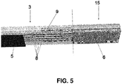
- a further embodiment alternative to that shown in Figure 3 is inserting a top 15 in insulating plastics having on its back a magnet 6 with high magnetic force, in a point far from conductors 8.
- Said embodiment is shown in Figure 5 .
- the conductors 8 end at the beginning of top 15 itself.
- the end of conductors 8 is highlighted in Figure 5 by the dotted line.
- the insulation 9 extends from the end of top 15 up to some centimetre of the top towards the inside of the rail 3, i.e. beyond the dotted line, always with the aim of preventing as much as possible that conductors 8 can attract metal powder.
Landscapes
- Engineering & Computer Science (AREA)
- Architecture (AREA)
- Civil Engineering (AREA)
- Structural Engineering (AREA)
- Package Frames And Binding Bands (AREA)
- Installation Of Indoor Wiring (AREA)
- Warehouses Or Storage Devices (AREA)
Description
- The present invention relates to the technical field of shopfitting for large scale retail, and in particular to a rail for electrifying shelving. More particularly, the invention relates to a rail provided with magnets, suitable for being releasably fixed to shelving.
- Said electrified rail was described in detail in patent application
EP2833490A1 of the same applicant; said document is here incorporated by reference. In short, said document describes a rail having a planar base (back portion) suitable for fixing to shelving, and a front part having a plurality of slots, each holding a metal conductor. The positioning of the metal conductors inside the slots is such as to at least expose part of the metal conductor; plugs can be plugged into said metal conductor in any position, said plugs supplying a plurality of electric/electronic devices: lamps for lighting the shelving, electric price tags, etc. - In the following, reference will be made to the front of the rail meaning the long side on which metal conductors are present, and which is available for plugging different plugs, and to the back of the rail meaning the long side, generally but not limitatively opposed to the front side, which is fixed to the shelving.
- In its present version, the rail is fixed to the shelving through simple double-sided tape. This system has several problems, mainly that the double-sided tape remains glued to the shelving when the rail is removed, soiling the shelving. Moreover, in some cases, when tearing, the double-sided tape can damage the shelving coating in some points. Once detached, the double-sided tape loses the most of its adhesive properties, so that the repositioning of the rail, and therefore its reuse, is unstable.
- Therefore a different fixing system was searched for, which is releasable and free from the above-quoted inconveniences. Said system was found in the use of magnets having a high magnetic force, having the advantage that they fix strongly to the shelving, which are usually made of metal. Nonetheless, this system is not free of problems, too.
- In fact, when the shelvings are mounted, often holes must be pierced in them through drills or hacksaws. This generates metal shavings and powder, which are attracted by the magnets positioned on the back of the rail: the metallic powder, attracted by magnets, forms a layer of metallic powder over the metallic conductors, potentially generating a short circuit, or anyway an abnormal closing of the circuit. This entails, after each working, the constant attention of the people mounting the shelvings to accurately clean the remains of the working on the rails, which is a delicate task.
- If the cleaning is not accurate, although the power supplies have several levels of protection against short-circuits, the metallic remains can overheat, generating dangerous conditions. Experimentally it was found that the higher the magnetic force, the more effective the force of the fixing of the rail to the shelving, but at the same time the higher the related dangers, too.
- This solution, interesting in theory, seemed not workable, even if the magnetic solution showed the best prerequisites, in that it needs neither special tools, nor holes on the shelving, and is totally repositionable and usable also on already set-up shelvings to retrofit them. The solution of the problem is made more difficult by the position of rails on the shelving, as rails are often positioned vertically, i.e. in a position more prone to intercept and gather cut remains falling from above. The typical position used on the market, i.e. rails positioned horizontally, with the uncovered conductors facing the floor, would have rendered the problem easier.
- Experimentally, the first possible solution used magnetic clips having small dimensions (about 20x15 mm) comprising magnets having high magnetic force. Taking into account the weight which has to be supported by the rail, indicatively four magnetic clips were necessary for each linear meter of rail, for an overall magnetic force of about 100 N for each linear meter of rail. Halving this value, the magnetic attraction of the rail to the shelving becomes poor, without eliminating the problem of the attraction of metallic powder on the front of the rail where conductors are uncovered.
- Document
WO2015015187 discloses a shelf power distribution apparatus comprises a track element further comprising a first electrical conductor and a first magnet; wherein said first magnet facilitates the attachment of said track element to a shelf; a first cover element that further comprises a second magnet; and wherein said second magnet facilitates the attachment of said cover to said track element. - Document
JP2002291131 - Aim of the present invention is providing a releasable fixing system of the rail to the metallic shelving, not soiling the shelving, allowing the detachment, the re-fixing and the free positioning of the rail, free from problems related to electrical safety, highly miniaturized and which is cheap and easy to manufacture.
- This object is achieved by an apparatus and a method having the features of the independent claims. Advantageous embodiment and refinements are specified in the claims dependent thereon.
- The solution consists in distributing the magnetic force along at least a relevant part or the whole length of the rail: in this way, there is always a minimal magnetic attraction of the rail along the whole shelf, without the collateral effect of attracting metallic powder on the rail front. As the magnetic force is locally distributed, relocating the rail is easy: this is a problem, particularly at the two ends of the rail, which are the rail areas more prone to bumps and jerks. Therefore, the refinement of the solution consists in using, in combination with said distributed magnetic force, also two permanent magnets provided with high magnetic force, insulating them on the front the metallic conductors.
- Although the magnetic fixture according to the present invention is disclosed in relation to an electrified rail and in combination with a metallic shelving, the same technical concept can be applied in equivalent solutions in which different kinds of peripheral devices are attached to the shelving, including LED lamps for promoting the growth of plants.
- Further advantages and properties of the present invention are subject matter of the dependent claims and/or are disclosed in the following description, in which exemplary embodiments of the present invention are explained in detail based on the drawings:
- Figure 1
- Axonometric view of a shelving with an electrified rail according to the present invention;
- Figure 2
- Axonometric view of a detail of
Figure 1 , showing the rail according to the present invention vertically fixed to the back panelling of the shelving; - Figure 3
- Axonometric view of an electrified rail according to the present invention;
- Figure 4
- Axonometric view of two serially connected rails;
- Figure 5
- Axonometric view of a terminal top for a rail.
- In the following description and in the introduction to the description and in the claims, the term magnetic force exercised by a magnet means the magnetic attraction force or repulsion force exercised by a magnet due to the intensity of the magnetic field generated by said magnet. Since the magnetic force exercised by a magnet on ferromagnetic material depends inter alia form the strength of the magnetic field or from the intensity of the magnetic field and this is a function of the magnetic flux generated by the magnet, there is a direct and parametrical relation between field strength or intensity and magnetic force exercised on a body by the said field. Thus it is clear that the terms like magnetic force strength and magnetic field intensity are related to one another.
-
Figure 1 shows a shelving 1 for points of sale comprising a plurality ofshelves 2 supporting therail 3 according to the present invention. -
Figure 2 shows a detail of shelving 1: here arail 3 vertically fixed to theback panelling 4 of shelving 1 thanks to the magnets according to the present invention is more easily visible. - As shown in
Figure 3 , on the base (back part) of the rail 3 amagnetic band 5 having low magnetic force is fixed for the whole length of the rail. Said magnet is absent at the two ends of therail 3, for a length of approximately 50 mm. At the two ends, wherein the low force magnet is absent, twomagnetic clips 13 are instead present, ensuring the grip of the rail to the shelving. - The
magnetic clip 13 comprises aninsulating adhesive 9 on its front, and a magnet having high magnetic force positioned on the back of therail 3, all enclosed in an insulatingplastic protection 7 which is steadily fixed to the rail and can be removed with a tool. Theplastic protection 7 and the electrical insulation cooperate with the aim of preventing that metallic powder adheres toconductors 8. - As already anticipated, the
high force magnet 6, having a magnetic force higher than 10 N/cm2, cannot be used near to thenon-insulated conductors 8, otherwise the magnetic force, having the good property of fixing to the metallic back panelling on its back, introduces the bad property of attracting metallic powders on the front, where non-insulatedconductors 8 are present., However, thehigh force magnet 6 is necessary because without it the rail does not stay in the desired position and is easily removed. Therefore, thehigh force magnet 6 must be used only in areas where theconductors 8 are absent or are insulated. As a consequence, thehigh force magnet 6 does not entail the risk of attracting metallic powders where non-insulated conductors are present. - The
magnet 6 with high magnetic force is not sufficient to ensure a good grip of therail 3 toback panelling 4, in that in the centre of therail 3, where freedom of electric contact is needed, said rail would be easily moved or removed from contact with shelving 1 when working on the electric plugging of peripheral devices. - The problem is solved through the use of a magnetic band with distributed magnetic force, which overall has a magnetic force towards the back panelling in the order of 80 N/linear meter of rail, but in the particular exerts a magnetic force lower than 1 N for each linear centimetre of rail. Said
magnetic band 5 with distributed force is fixed in a steady way on the back of therail 3, e.g. through glue or screws. - This means that the magnetic force of the
magnetic band 5 is significant over the length of a metre of rail, but is very small if considered on a small number of centimetres. As the magnetic band is positioned on the base of therail 3, and the rail has the conductors at about 3 mm of distance, the magnetic force on the conductors' side is negligible and not sufficient to attract metal powder. - The combination of two
magnetic clips 13 with high magnetic force and of aband 5 with distributed force allows to obtain a fixing system which is strong enough, but at the same time safe, in that it does not attract metal powder over the uncoveredconductors 8. From the above description, it is clear that the use of themagnets 6 with high magnetic force only, or of the magnetic band with distributed magnetic force only would not obtain the desired aim. - In this way, the rail can be easily positioned in any desired position. Moreover, this fixing system allows to fix the electrified rail as a retrofit on any kind of metallic shelving, even already set up in a point of sale, and optionally even if the shelving is already supporting goods.
- The weight of the peripheral devices supplied by the
conductors 8 can be such that therail 3 tends to detach from shelving 1. In this case, one or more furthermagnetic clips 13 can be inserted in an intermediate point of therail 3. - An alternative embodiment is the combination of a
magnet 6 with high magnetic force, aninsulation 9 on the front of therail 3, and aprotection 7 in insulating plastics to get theserial connection 14 of tworails 3. In this embodiment, shown inFigure 4 , themagnet 6 with high magnetic force is placed over the twoadjacent rails 3, while theplastic protection 7 and theinsulation 9 extend for a length longer than the length of the magnet itself. It is worth noting that the connection between theconductors 8 belonging to twodistinct rails 3 is made through a (not shown) electronic board suitable for contacting theconductors 8 of the first and of the second rail. - A further embodiment alternative to that shown in
Figure 3 is inserting a top 15 in insulating plastics having on its back amagnet 6 with high magnetic force, in a point far fromconductors 8. Said embodiment is shown inFigure 5 . In this embodiment, theconductors 8 end at the beginning of top 15 itself. The end ofconductors 8 is highlighted inFigure 5 by the dotted line. In this particular case, theinsulation 9 extends from the end of top 15 up to some centimetre of the top towards the inside of therail 3, i.e. beyond the dotted line, always with the aim of preventing as much as possible thatconductors 8 can attract metal powder. - 1 shelving
- 2 shelf
- 3 rail
- 4 back panelling
- 5 band with distributed magnetic force
- 6 magnet with high magnetic force
- 7 plastic protection
- 8 conductors
- 9 insulation
- 13 magnetic clip
- 14 connection between two rails
- 15 end top
Claims (9)
- Magnetic fixing system comprising an electrified rail (3) and a metal shelving, particularly for the electrification of metal shelving (1) units provided on their front of electronic labels, displays and/or other peripheral devices, said shelving (1) comprising at least one shelf; said rail (3) comprising a body of electrically insulating plastic material, provided with longitudinal slots suitably distanced to each other, in every one of which metal conductor (8) is housed and can be reached by an electric contact useful to connect the same conductor to a plug or an electric or electronic device, fixed to said body of the rail (3),
said rail (3) further comprises magnetic fixing elements (5, 6) of the said rail to the metal shelving
characterized in that- the said rail (3) is provided with two kinds of magnets (5, 6) which generate magnetic fields having a different intensity or magnetic flux, one (5) of the two kinds of magnets generating a magnetic field with a lower intensity than the other kind (6) of magnets:- the magnets (5) generating the lower magnetic is configured to distributing the magnetic force along the length of the rail (3);- the magnets (6) generating the magnetic field having the higher intensity are placed at the ends of the said rail (3) and are insulated from the metallic conductors (8) at the side of the rail (3) opposite to the side adhering the shelving (1);- the magnet (5) generating the magnetic field with the lower or weaker intensity exercises an attraction force relatively to the metal shelving (1) which is lower than 1 N/cm2 and the magnets (6) generating the magnetic field having a higher intensity exercises an attraction force one the metal shelving (1) in the order of at least 10 N/cm2. - Magnetic fixing system according to claim 1, wherein the magnet (5) generating the magnetic field with the lower intensity has a length which is slightly shorter than the rail (3) itself.
- Magnetic fixing system according to claim 1 or 2, wherein the magnet (6) generating the magnetic field with the higher intensity has a length of at least 20 mm.
- Magnetic fixing system according to one or more of claims 1 to 3, wherein the magnet (6)) generating the magnetic field with the higher intensity, positioned on the back of the rail (3), is included inside a magnetic clip (13) comprising on the front side of the rail (3) an insulation (9), and a plastic protection (7) covering the four long sides of the rail (3).
- Magnetic fixing system according to one or more of claims 1 to 4, wherein at least two magnetic clips (13) are positioned at the two ends of the rail (3) itself, and optionally at least a further magnetic clip (13) is placed between the two magnetic clips (13) placed at the two ends of the rail.
- Magnetic fixing system according to one or more of the preceding claims characterized in that it forms a connecting element (14) between a first and a second sequentially positioned adjacent rails (3), the magnet (6) generating a magnetic field having an intensity to exercise a high magnetic attraction force, of at least 10 N/cm2 being placed over the said two rails (3), wherein the protection (7) and the insulation (9) extend for a length which is longer than the magnet (6) itself, and being provided an electronic board suitable for putting into contact the conductors (8) of said first and second rail (3).
- Magnetic fixing system according to one or more of the preceding claims 1 to 5 characterized in that it comprises a terminal top (15) in plastic to be placed at an end of a rail (3), the said terminal top being associated to the magnet generating a magnetic field having an intensity to exercise a with high magnetic attraction force, of at least 10 N/cm2, placed on the back of the rail (3) itself, an insulation (9) placed on the front side of the rail (3) having a length which is longer than that of the top itself, and wherein the metallic conductors (8) end at the proximal end of the top, and are covered for a length similar to that of the top by an insulation (9) placed on the front of the rail (3).
- Magnetic fixing system according to claim 1 or one or more of the claims 2 to 7, characterized in that- said rail (3) comprising a body of electrically insulating plastic material, provided with longitudinal slots suitably distanced from each other, in every one of which a wire or strand (8) of electrically conducing metal is housed which wire or strand is surrounded for more than 180° of its section by the internal walls of the respective slot to be friction-held in it, so that for the remaining section the same wire or strand (8) is free and can be reached by an electric contact configured to connect the same conductor to a plug or an electric or electronic device, fixed to said body of the rail,- wherein the body of the rail (3) itself is formed in a monolithic way and with any plastic material mechanically resistant, with a high degree of electric insulation and a high thermal resistance, and- wherein said slots for holding the wires or strands (8) are positioned one beside the other, and after the surrounding and holding of the wires (8) the slots are open on a visible planar side of the rail body, with longitudinal mouths having a width always inferior to the diameter of the wires or strands (8);- the depth of the slots being perpendicular to said visible side and having a value sufficient for wire (8) to be ditched and protected in the slots surrounding the wires or strands (8) for more than 180° of their section, the wires or strands (8) being held in slots by the toughness and structural non-deformability of the material forming the monolithic body of the rail itself, while through the narrow mouths of said slots every electric wire or strand can be reached by the spring-loaded contacts of plugs or of devices mounted on the monolithic body itself of the rail (3).
- Method for releasably fixing to a shelving (1) for point of sales at least an electrified rail (3) in any direction and/or position, said method making use of the magnetic fixing system according to one of claims 1 to 8.
Priority Applications (1)
| Application Number | Priority Date | Filing Date | Title |
|---|---|---|---|
| PL16178013T PL3116079T3 (en) | 2015-07-07 | 2016-07-05 | Magnetic fixing system for an electrified rail |
Applications Claiming Priority (1)
| Application Number | Priority Date | Filing Date | Title |
|---|---|---|---|
| ITUB2015A001917A ITUB20151917A1 (en) | 2015-07-07 | 2015-07-07 | ELECTRIFIED RAIL WITH MAGNETS |
Publications (3)
| Publication Number | Publication Date |
|---|---|
| EP3116079A2 EP3116079A2 (en) | 2017-01-11 |
| EP3116079A3 EP3116079A3 (en) | 2017-04-26 |
| EP3116079B1 true EP3116079B1 (en) | 2019-09-25 |
Family
ID=54064538
Family Applications (1)
| Application Number | Title | Priority Date | Filing Date |
|---|---|---|---|
| EP16178013.5A Active EP3116079B1 (en) | 2015-07-07 | 2016-07-05 | Magnetic fixing system for an electrified rail |
Country Status (4)
| Country | Link |
|---|---|
| EP (1) | EP3116079B1 (en) |
| ES (1) | ES2755524T3 (en) |
| IT (1) | ITUB20151917A1 (en) |
| PL (1) | PL3116079T3 (en) |
Families Citing this family (1)
| Publication number | Priority date | Publication date | Assignee | Title |
|---|---|---|---|---|
| EP4323985A1 (en) * | 2021-04-13 | 2024-02-21 | SES-Imagotag GmbH | Support device for supporting an electronic device within a receiving area for the support device |
Family Cites Families (7)
| Publication number | Priority date | Publication date | Assignee | Title |
|---|---|---|---|---|
| DE1083882B (en) * | 1957-02-09 | 1960-06-23 | Max Baermann | Self-adhesive electrical wire |
| JP2002291131A (en) * | 2001-03-28 | 2002-10-04 | Ntt Comware Corp | Cable protector and pedestal for cable protector |
| US6855890B1 (en) * | 2003-07-22 | 2005-02-15 | Richard Vasichek | Brackets and methods for holding wires utilizing magnetic force |
| US9472937B2 (en) * | 2010-08-27 | 2016-10-18 | Metal & Cable Corp., Inc. | Cable/cable tray mount |
| US8979311B2 (en) * | 2012-03-19 | 2015-03-17 | Madix, Inc. | Power supply system for adjustable shelving |
| ITBO20130415A1 (en) * | 2013-07-31 | 2015-02-01 | Cefla Coop | ELECTRIFIED RAIL, PARTICULARLY FOR THE ELECTRIFICATION OF METAL SHELVES, AND PROCEDURE FOR ITS PRODUCTION |
| GB2516853B (en) * | 2013-08-01 | 2016-09-14 | Clark-Ward Gary | A shelf power distribution apparatus |
-
2015
- 2015-07-07 IT ITUB2015A001917A patent/ITUB20151917A1/en unknown
-
2016
- 2016-07-05 ES ES16178013T patent/ES2755524T3/en active Active
- 2016-07-05 EP EP16178013.5A patent/EP3116079B1/en active Active
- 2016-07-05 PL PL16178013T patent/PL3116079T3/en unknown
Non-Patent Citations (1)
| Title |
|---|
| None * |
Also Published As
| Publication number | Publication date |
|---|---|
| EP3116079A3 (en) | 2017-04-26 |
| ES2755524T3 (en) | 2020-04-22 |
| EP3116079A2 (en) | 2017-01-11 |
| ITUB20151917A1 (en) | 2017-01-07 |
| PL3116079T3 (en) | 2020-02-28 |
Similar Documents
| Publication | Publication Date | Title |
|---|---|---|
| US9885467B2 (en) | Low voltage power supply for a merchandise display system | |
| US9057513B2 (en) | Electrical assembly for connecting components of a lighting system for illuminating store shelving | |
| EP3260018B1 (en) | Power supply system for shelving system | |
| EP3742939B1 (en) | Merchandise display with low voltage power system | |
| KR101662814B1 (en) | Prefabricated display stand with lighting function | |
| US20130279165A1 (en) | Stringed LED Capsule Lighting Apparatus | |
| DE60000849D1 (en) | Electrical connector for quick connection of two parallel circuit boards | |
| WO2016191164A2 (en) | Modular shelving systems, magnetic electrical connectors, conductor assemblies, and mounting inserts | |
| EP3027957A1 (en) | A shelf power distribution apparatus | |
| EP3116079A2 (en) | Electrified rail provided with magnets | |
| US9595210B1 (en) | Cable marking system | |
| EP3131440B1 (en) | Merchandise display | |
| TW545784U (en) | Electrical connector with wire management apparatus | |
| DE60036846D1 (en) | Electrical connector with connector locator | |
| KR200146721Y1 (en) | Connection terminal fixture for power distribution | |
| CN215451967U (en) | Formula goods shelves transmission of electricity device is inhaled to magnetism | |
| ITFI990055V0 (en) | CABLE CLAMP FOR ELECTRICAL EQUIPMENT | |
| KR20150008601A (en) | Terminal Structure for Distributing Electric Power | |
| EP0993074A3 (en) | Connector base for a coil device | |
| KR20150113995A (en) | Pole hidden type outlet for display stand | |
| EP3060032A1 (en) | Power terminal | |
| SE538769C2 (en) | Power Terminal | |
| EP1921718A2 (en) | Electrified structural shape for carrying structures for indoor furnishing | |
| ES1055167U (en) | Electrical safety device to scare pest birds. (Machine-translation by Google Translate, not legally binding) | |
| PL66616Y1 (en) | Showcase |
Legal Events
| Date | Code | Title | Description |
|---|---|---|---|
| PUAI | Public reference made under article 153(3) epc to a published international application that has entered the european phase |
Free format text: ORIGINAL CODE: 0009012 |
|
| STAA | Information on the status of an ep patent application or granted ep patent |
Free format text: STATUS: THE APPLICATION HAS BEEN PUBLISHED |
|
| AK | Designated contracting states |
Kind code of ref document: A2 Designated state(s): AL AT BE BG CH CY CZ DE DK EE ES FI FR GB GR HR HU IE IS IT LI LT LU LV MC MK MT NL NO PL PT RO RS SE SI SK SM TR |
|
| AX | Request for extension of the european patent |
Extension state: BA ME |
|
| PUAL | Search report despatched |
Free format text: ORIGINAL CODE: 0009013 |
|
| AK | Designated contracting states |
Kind code of ref document: A3 Designated state(s): AL AT BE BG CH CY CZ DE DK EE ES FI FR GB GR HR HU IE IS IT LI LT LU LV MC MK MT NL NO PL PT RO RS SE SI SK SM TR |
|
| AX | Request for extension of the european patent |
Extension state: BA ME |
|
| RIC1 | Information provided on ipc code assigned before grant |
Ipc: H02G 3/30 20060101AFI20170321BHEP |
|
| STAA | Information on the status of an ep patent application or granted ep patent |
Free format text: STATUS: REQUEST FOR EXAMINATION WAS MADE |
|
| 17P | Request for examination filed |
Effective date: 20171025 |
|
| RBV | Designated contracting states (corrected) |
Designated state(s): AL AT BE BG CH CY CZ DE DK EE ES FI FR GB GR HR HU IE IS IT LI LT LU LV MC MK MT NL NO PL PT RO RS SE SI SK SM TR |
|
| GRAP | Despatch of communication of intention to grant a patent |
Free format text: ORIGINAL CODE: EPIDOSNIGR1 |
|
| STAA | Information on the status of an ep patent application or granted ep patent |
Free format text: STATUS: GRANT OF PATENT IS INTENDED |
|
| RIC1 | Information provided on ipc code assigned before grant |
Ipc: H02G 3/30 20060101AFI20190509BHEP Ipc: H01R 25/14 20060101ALN20190509BHEP |
|
| RIC1 | Information provided on ipc code assigned before grant |
Ipc: H02G 3/30 20060101AFI20190510BHEP Ipc: H01R 25/14 20060101ALN20190510BHEP |
|
| INTG | Intention to grant announced |
Effective date: 20190603 |
|
| GRAS | Grant fee paid |
Free format text: ORIGINAL CODE: EPIDOSNIGR3 |
|
| GRAA | (expected) grant |
Free format text: ORIGINAL CODE: 0009210 |
|
| STAA | Information on the status of an ep patent application or granted ep patent |
Free format text: STATUS: THE PATENT HAS BEEN GRANTED |
|
| AK | Designated contracting states |
Kind code of ref document: B1 Designated state(s): AL AT BE BG CH CY CZ DE DK EE ES FI FR GB GR HR HU IE IS IT LI LT LU LV MC MK MT NL NO PL PT RO RS SE SI SK SM TR |
|
| REG | Reference to a national code |
Ref country code: GB Ref legal event code: FG4D |
|
| REG | Reference to a national code |
Ref country code: CH Ref legal event code: EP |
|
| REG | Reference to a national code |
Ref country code: AT Ref legal event code: REF Ref document number: 1184760 Country of ref document: AT Kind code of ref document: T Effective date: 20191015 |
|
| REG | Reference to a national code |
Ref country code: IE Ref legal event code: FG4D |
|
| REG | Reference to a national code |
Ref country code: DE Ref legal event code: R096 Ref document number: 602016021123 Country of ref document: DE |
|
| REG | Reference to a national code |
Ref country code: NL Ref legal event code: MP Effective date: 20190925 |
|
| PG25 | Lapsed in a contracting state [announced via postgrant information from national office to epo] |
Ref country code: BG Free format text: LAPSE BECAUSE OF FAILURE TO SUBMIT A TRANSLATION OF THE DESCRIPTION OR TO PAY THE FEE WITHIN THE PRESCRIBED TIME-LIMIT Effective date: 20191225 Ref country code: LT Free format text: LAPSE BECAUSE OF FAILURE TO SUBMIT A TRANSLATION OF THE DESCRIPTION OR TO PAY THE FEE WITHIN THE PRESCRIBED TIME-LIMIT Effective date: 20190925 Ref country code: HR Free format text: LAPSE BECAUSE OF FAILURE TO SUBMIT A TRANSLATION OF THE DESCRIPTION OR TO PAY THE FEE WITHIN THE PRESCRIBED TIME-LIMIT Effective date: 20190925 Ref country code: SE Free format text: LAPSE BECAUSE OF FAILURE TO SUBMIT A TRANSLATION OF THE DESCRIPTION OR TO PAY THE FEE WITHIN THE PRESCRIBED TIME-LIMIT Effective date: 20190925 Ref country code: NO Free format text: LAPSE BECAUSE OF FAILURE TO SUBMIT A TRANSLATION OF THE DESCRIPTION OR TO PAY THE FEE WITHIN THE PRESCRIBED TIME-LIMIT Effective date: 20191225 Ref country code: FI Free format text: LAPSE BECAUSE OF FAILURE TO SUBMIT A TRANSLATION OF THE DESCRIPTION OR TO PAY THE FEE WITHIN THE PRESCRIBED TIME-LIMIT Effective date: 20190925 |
|
| REG | Reference to a national code |
Ref country code: LT Ref legal event code: MG4D |
|
| PG25 | Lapsed in a contracting state [announced via postgrant information from national office to epo] |
Ref country code: RS Free format text: LAPSE BECAUSE OF FAILURE TO SUBMIT A TRANSLATION OF THE DESCRIPTION OR TO PAY THE FEE WITHIN THE PRESCRIBED TIME-LIMIT Effective date: 20190925 Ref country code: LV Free format text: LAPSE BECAUSE OF FAILURE TO SUBMIT A TRANSLATION OF THE DESCRIPTION OR TO PAY THE FEE WITHIN THE PRESCRIBED TIME-LIMIT Effective date: 20190925 Ref country code: GR Free format text: LAPSE BECAUSE OF FAILURE TO SUBMIT A TRANSLATION OF THE DESCRIPTION OR TO PAY THE FEE WITHIN THE PRESCRIBED TIME-LIMIT Effective date: 20191226 |
|
| REG | Reference to a national code |
Ref country code: AT Ref legal event code: MK05 Ref document number: 1184760 Country of ref document: AT Kind code of ref document: T Effective date: 20190925 |
|
| REG | Reference to a national code |
Ref country code: ES Ref legal event code: FG2A Ref document number: 2755524 Country of ref document: ES Kind code of ref document: T3 Effective date: 20200422 |
|
| PG25 | Lapsed in a contracting state [announced via postgrant information from national office to epo] |
Ref country code: PT Free format text: LAPSE BECAUSE OF FAILURE TO SUBMIT A TRANSLATION OF THE DESCRIPTION OR TO PAY THE FEE WITHIN THE PRESCRIBED TIME-LIMIT Effective date: 20200127 Ref country code: RO Free format text: LAPSE BECAUSE OF FAILURE TO SUBMIT A TRANSLATION OF THE DESCRIPTION OR TO PAY THE FEE WITHIN THE PRESCRIBED TIME-LIMIT Effective date: 20190925 Ref country code: AT Free format text: LAPSE BECAUSE OF FAILURE TO SUBMIT A TRANSLATION OF THE DESCRIPTION OR TO PAY THE FEE WITHIN THE PRESCRIBED TIME-LIMIT Effective date: 20190925 Ref country code: EE Free format text: LAPSE BECAUSE OF FAILURE TO SUBMIT A TRANSLATION OF THE DESCRIPTION OR TO PAY THE FEE WITHIN THE PRESCRIBED TIME-LIMIT Effective date: 20190925 Ref country code: NL Free format text: LAPSE BECAUSE OF FAILURE TO SUBMIT A TRANSLATION OF THE DESCRIPTION OR TO PAY THE FEE WITHIN THE PRESCRIBED TIME-LIMIT Effective date: 20190925 Ref country code: AL Free format text: LAPSE BECAUSE OF FAILURE TO SUBMIT A TRANSLATION OF THE DESCRIPTION OR TO PAY THE FEE WITHIN THE PRESCRIBED TIME-LIMIT Effective date: 20190925 |
|
| PG25 | Lapsed in a contracting state [announced via postgrant information from national office to epo] |
Ref country code: IS Free format text: LAPSE BECAUSE OF FAILURE TO SUBMIT A TRANSLATION OF THE DESCRIPTION OR TO PAY THE FEE WITHIN THE PRESCRIBED TIME-LIMIT Effective date: 20200224 Ref country code: SK Free format text: LAPSE BECAUSE OF FAILURE TO SUBMIT A TRANSLATION OF THE DESCRIPTION OR TO PAY THE FEE WITHIN THE PRESCRIBED TIME-LIMIT Effective date: 20190925 Ref country code: SM Free format text: LAPSE BECAUSE OF FAILURE TO SUBMIT A TRANSLATION OF THE DESCRIPTION OR TO PAY THE FEE WITHIN THE PRESCRIBED TIME-LIMIT Effective date: 20190925 Ref country code: CZ Free format text: LAPSE BECAUSE OF FAILURE TO SUBMIT A TRANSLATION OF THE DESCRIPTION OR TO PAY THE FEE WITHIN THE PRESCRIBED TIME-LIMIT Effective date: 20190925 |
|
| REG | Reference to a national code |
Ref country code: DE Ref legal event code: R097 Ref document number: 602016021123 Country of ref document: DE |
|
| PG2D | Information on lapse in contracting state deleted |
Ref country code: IS |
|
| PG25 | Lapsed in a contracting state [announced via postgrant information from national office to epo] |
Ref country code: DK Free format text: LAPSE BECAUSE OF FAILURE TO SUBMIT A TRANSLATION OF THE DESCRIPTION OR TO PAY THE FEE WITHIN THE PRESCRIBED TIME-LIMIT Effective date: 20190925 Ref country code: IS Free format text: LAPSE BECAUSE OF FAILURE TO SUBMIT A TRANSLATION OF THE DESCRIPTION OR TO PAY THE FEE WITHIN THE PRESCRIBED TIME-LIMIT Effective date: 20200126 |
|
| PLBE | No opposition filed within time limit |
Free format text: ORIGINAL CODE: 0009261 |
|
| STAA | Information on the status of an ep patent application or granted ep patent |
Free format text: STATUS: NO OPPOSITION FILED WITHIN TIME LIMIT |
|
| 26N | No opposition filed |
Effective date: 20200626 |
|
| PG25 | Lapsed in a contracting state [announced via postgrant information from national office to epo] |
Ref country code: SI Free format text: LAPSE BECAUSE OF FAILURE TO SUBMIT A TRANSLATION OF THE DESCRIPTION OR TO PAY THE FEE WITHIN THE PRESCRIBED TIME-LIMIT Effective date: 20190925 |
|
| PG25 | Lapsed in a contracting state [announced via postgrant information from national office to epo] |
Ref country code: MC Free format text: LAPSE BECAUSE OF FAILURE TO SUBMIT A TRANSLATION OF THE DESCRIPTION OR TO PAY THE FEE WITHIN THE PRESCRIBED TIME-LIMIT Effective date: 20190925 |
|
| REG | Reference to a national code |
Ref country code: CH Ref legal event code: PL |
|
| REG | Reference to a national code |
Ref country code: BE Ref legal event code: MM Effective date: 20200731 |
|
| PG25 | Lapsed in a contracting state [announced via postgrant information from national office to epo] |
Ref country code: LU Free format text: LAPSE BECAUSE OF NON-PAYMENT OF DUE FEES Effective date: 20200705 Ref country code: LI Free format text: LAPSE BECAUSE OF NON-PAYMENT OF DUE FEES Effective date: 20200731 Ref country code: CH Free format text: LAPSE BECAUSE OF NON-PAYMENT OF DUE FEES Effective date: 20200731 Ref country code: IE Free format text: LAPSE BECAUSE OF NON-PAYMENT OF DUE FEES Effective date: 20200705 |
|
| REG | Reference to a national code |
Ref country code: DE Ref legal event code: R082 Ref document number: 602016021123 Country of ref document: DE Representative=s name: DEHNS, DE Ref country code: DE Ref legal event code: R081 Ref document number: 602016021123 Country of ref document: DE Owner name: IMOLA RETAIL SOLUTIONS S.R.L., IMOLA, IT Free format text: FORMER OWNER: CEFLA SOCIETA' COOPERATIVA, IMOLA, IT Ref country code: DE Ref legal event code: R082 Ref document number: 602016021123 Country of ref document: DE Representative=s name: DEHNS PATENT AND TRADEMARK ATTORNEYS, DE |
|
| PG25 | Lapsed in a contracting state [announced via postgrant information from national office to epo] |
Ref country code: BE Free format text: LAPSE BECAUSE OF NON-PAYMENT OF DUE FEES Effective date: 20200731 |
|
| REG | Reference to a national code |
Ref country code: ES Ref legal event code: PC2A Owner name: IMOLA RETAIL SOLUTIONS S.R.L. Effective date: 20210608 |
|
| REG | Reference to a national code |
Ref country code: GB Ref legal event code: 732E Free format text: REGISTERED BETWEEN 20210617 AND 20210623 |
|
| PG25 | Lapsed in a contracting state [announced via postgrant information from national office to epo] |
Ref country code: TR Free format text: LAPSE BECAUSE OF FAILURE TO SUBMIT A TRANSLATION OF THE DESCRIPTION OR TO PAY THE FEE WITHIN THE PRESCRIBED TIME-LIMIT Effective date: 20190925 Ref country code: MT Free format text: LAPSE BECAUSE OF FAILURE TO SUBMIT A TRANSLATION OF THE DESCRIPTION OR TO PAY THE FEE WITHIN THE PRESCRIBED TIME-LIMIT Effective date: 20190925 Ref country code: CY Free format text: LAPSE BECAUSE OF FAILURE TO SUBMIT A TRANSLATION OF THE DESCRIPTION OR TO PAY THE FEE WITHIN THE PRESCRIBED TIME-LIMIT Effective date: 20190925 |
|
| PG25 | Lapsed in a contracting state [announced via postgrant information from national office to epo] |
Ref country code: MK Free format text: LAPSE BECAUSE OF FAILURE TO SUBMIT A TRANSLATION OF THE DESCRIPTION OR TO PAY THE FEE WITHIN THE PRESCRIBED TIME-LIMIT Effective date: 20190925 |
|
| PGFP | Annual fee paid to national office [announced via postgrant information from national office to epo] |
Ref country code: IT Payment date: 20220621 Year of fee payment: 7 Ref country code: GB Payment date: 20220621 Year of fee payment: 7 |
|
| PGFP | Annual fee paid to national office [announced via postgrant information from national office to epo] |
Ref country code: PL Payment date: 20220627 Year of fee payment: 7 |
|
| PGFP | Annual fee paid to national office [announced via postgrant information from national office to epo] |
Ref country code: FR Payment date: 20220622 Year of fee payment: 7 |
|
| PGFP | Annual fee paid to national office [announced via postgrant information from national office to epo] |
Ref country code: ES Payment date: 20220801 Year of fee payment: 7 Ref country code: DE Payment date: 20220621 Year of fee payment: 7 |
|
| REG | Reference to a national code |
Ref country code: DE Ref legal event code: R119 Ref document number: 602016021123 Country of ref document: DE |
|
| GBPC | Gb: european patent ceased through non-payment of renewal fee |
Effective date: 20230705 |
|
| PG25 | Lapsed in a contracting state [announced via postgrant information from national office to epo] |
Ref country code: DE Free format text: LAPSE BECAUSE OF NON-PAYMENT OF DUE FEES Effective date: 20240201 Ref country code: GB Free format text: LAPSE BECAUSE OF NON-PAYMENT OF DUE FEES Effective date: 20230705 |
|
| PG25 | Lapsed in a contracting state [announced via postgrant information from national office to epo] |
Ref country code: FR Free format text: LAPSE BECAUSE OF NON-PAYMENT OF DUE FEES Effective date: 20230731 |
|
| PG25 | Lapsed in a contracting state [announced via postgrant information from national office to epo] |
Ref country code: IT Free format text: LAPSE BECAUSE OF NON-PAYMENT OF DUE FEES Effective date: 20230705 |
|
| REG | Reference to a national code |
Ref country code: ES Ref legal event code: FD2A Effective date: 20240826 |
|
| PG25 | Lapsed in a contracting state [announced via postgrant information from national office to epo] |
Ref country code: ES Free format text: LAPSE BECAUSE OF NON-PAYMENT OF DUE FEES Effective date: 20230706 |
|
| PG25 | Lapsed in a contracting state [announced via postgrant information from national office to epo] |
Ref country code: ES Free format text: LAPSE BECAUSE OF NON-PAYMENT OF DUE FEES Effective date: 20230706 |
|
| PG25 | Lapsed in a contracting state [announced via postgrant information from national office to epo] |
Ref country code: PL Free format text: LAPSE BECAUSE OF NON-PAYMENT OF DUE FEES Effective date: 20230705 |
|
| PG25 | Lapsed in a contracting state [announced via postgrant information from national office to epo] |
Ref country code: PL Free format text: LAPSE BECAUSE OF NON-PAYMENT OF DUE FEES Effective date: 20230705 |