EP3116057A1 - Storage battery control apparatus and storage battery control method - Google Patents
Storage battery control apparatus and storage battery control method Download PDFInfo
- Publication number
- EP3116057A1 EP3116057A1 EP15759353.4A EP15759353A EP3116057A1 EP 3116057 A1 EP3116057 A1 EP 3116057A1 EP 15759353 A EP15759353 A EP 15759353A EP 3116057 A1 EP3116057 A1 EP 3116057A1
- Authority
- EP
- European Patent Office
- Prior art keywords
- charge
- storage battery
- discharge
- soc
- range
- Prior art date
- Legal status (The legal status is an assumption and is not a legal conclusion. Google has not performed a legal analysis and makes no representation as to the accuracy of the status listed.)
- Granted
Links
Images





Classifications
-
- H—ELECTRICITY
- H01—ELECTRIC ELEMENTS
- H01M—PROCESSES OR MEANS, e.g. BATTERIES, FOR THE DIRECT CONVERSION OF CHEMICAL ENERGY INTO ELECTRICAL ENERGY
- H01M10/00—Secondary cells; Manufacture thereof
- H01M10/42—Methods or arrangements for servicing or maintenance of secondary cells or secondary half-cells
- H01M10/48—Accumulators combined with arrangements for measuring, testing or indicating the condition of cells, e.g. the level or density of the electrolyte
- H01M10/482—Accumulators combined with arrangements for measuring, testing or indicating the condition of cells, e.g. the level or density of the electrolyte for several batteries or cells simultaneously or sequentially
-
- H—ELECTRICITY
- H02—GENERATION; CONVERSION OR DISTRIBUTION OF ELECTRIC POWER
- H02J—ELECTRIC POWER NETWORKS; CIRCUIT ARRANGEMENTS OR SYSTEMS FOR SUPPLYING OR DISTRIBUTING ELECTRIC POWER; SYSTEMS FOR STORING ELECTRIC ENERGY
- H02J7/00—Circuit arrangements for charging or discharging batteries or for supplying loads from batteries
- H02J7/50—Circuit arrangements for charging or discharging batteries or for supplying loads from batteries acting upon multiple batteries simultaneously or sequentially
-
- H—ELECTRICITY
- H02—GENERATION; CONVERSION OR DISTRIBUTION OF ELECTRIC POWER
- H02J—ELECTRIC POWER NETWORKS; CIRCUIT ARRANGEMENTS OR SYSTEMS FOR SUPPLYING OR DISTRIBUTING ELECTRIC POWER; SYSTEMS FOR STORING ELECTRIC ENERGY
- H02J7/00—Circuit arrangements for charging or discharging batteries or for supplying loads from batteries
- H02J7/80—Circuit arrangements for charging or discharging batteries or for supplying loads from batteries including monitoring or indicating arrangements
- H02J7/82—Control of state of charge [SOC]
-
- H—ELECTRICITY
- H02—GENERATION; CONVERSION OR DISTRIBUTION OF ELECTRIC POWER
- H02J—ELECTRIC POWER NETWORKS; CIRCUIT ARRANGEMENTS OR SYSTEMS FOR SUPPLYING OR DISTRIBUTING ELECTRIC POWER; SYSTEMS FOR STORING ELECTRIC ENERGY
- H02J7/00—Circuit arrangements for charging or discharging batteries or for supplying loads from batteries
- H02J7/90—Regulation of charging or discharging current or voltage
- H02J7/94—Regulation of charging or discharging current or voltage in response to battery current
-
- H—ELECTRICITY
- H01—ELECTRIC ELEMENTS
- H01M—PROCESSES OR MEANS, e.g. BATTERIES, FOR THE DIRECT CONVERSION OF CHEMICAL ENERGY INTO ELECTRICAL ENERGY
- H01M10/00—Secondary cells; Manufacture thereof
- H01M10/42—Methods or arrangements for servicing or maintenance of secondary cells or secondary half-cells
- H01M10/44—Methods for charging or discharging
- H01M10/441—Methods for charging or discharging for several batteries or cells simultaneously or sequentially
-
- H—ELECTRICITY
- H02—GENERATION; CONVERSION OR DISTRIBUTION OF ELECTRIC POWER
- H02J—ELECTRIC POWER NETWORKS; CIRCUIT ARRANGEMENTS OR SYSTEMS FOR SUPPLYING OR DISTRIBUTING ELECTRIC POWER; SYSTEMS FOR STORING ELECTRIC ENERGY
- H02J7/00—Circuit arrangements for charging or discharging batteries or for supplying loads from batteries
- H02J7/40—Circuit arrangements for charging or discharging batteries or for supplying loads from batteries characterised by the exchange of charge or discharge related data
- H02J7/42—Circuit arrangements for charging or discharging batteries or for supplying loads from batteries characterised by the exchange of charge or discharge related data with electronic devices having internal batteries, e.g. mobile phones
-
- Y—GENERAL TAGGING OF NEW TECHNOLOGICAL DEVELOPMENTS; GENERAL TAGGING OF CROSS-SECTIONAL TECHNOLOGIES SPANNING OVER SEVERAL SECTIONS OF THE IPC; TECHNICAL SUBJECTS COVERED BY FORMER USPC CROSS-REFERENCE ART COLLECTIONS [XRACs] AND DIGESTS
- Y02—TECHNOLOGIES OR APPLICATIONS FOR MITIGATION OR ADAPTATION AGAINST CLIMATE CHANGE
- Y02E—REDUCTION OF GREENHOUSE GAS [GHG] EMISSIONS, RELATED TO ENERGY GENERATION, TRANSMISSION OR DISTRIBUTION
- Y02E60/00—Enabling technologies; Technologies with a potential or indirect contribution to GHG emissions mitigation
- Y02E60/10—Energy storage using batteries
Definitions
- Embodiments of the invention relate to a storage battery control device, and a storage battery control method.
- LFC load frequency control
- the raising command and the lowering command are controlled to be entirely uniform.
- the power storage residual amount of the storage battery decreases due to a charge and discharge loss in the storage battery, and thus, finally, it is difficult to cope with the raising command (discharge command for the storage battery).
- a command value is inclined to a charge direction at a certain time zone, and thus charge is carried out to the capacity upper limit of the storage battery, and a chargeable electric power amount may be zero.
- an operation range which is a dynamic range of state of charge (SOC) for each storage battery
- SOC state of charge
- storage battery information including a charge performance and a battery residual amount of a plurality of storage batteries is acquired for a constant time interval, and the charge and discharge are controlled on the basis of the storage battery information.
- a storage battery control device in embodiments comprises a first reception unit, a second reception unit, a calculation unit, a generation unit, and a transmission unit.
- the first reception unit receives a charge and discharge command from a power management device.
- the second reception unit receives a current electricity storage state from each of a plurality of storage batteries.
- the calculation unit calculates a control amount, which indicates a ratio of the current electricity storage state in an operation range, with respect to each of the plurality of storage batteries on the basis of the current electricity storage state and the operation range of the electricity storage state.
- the generation unit generates a charge and discharge output value, which is an output value of charge and discharge for the each of the plurality of storage batteries, on the basis of the control amount that is calculated for each of the plurality of storage batteries, and the charge and discharge command that is received.
- the transmission unit transmits the charge and discharge output value, which is generated, to each of the plurality of storage batteries.
- FIG. 1 is a diagram illustrating an example of an entire configuration of a storage battery control system according to a first embodiment.
- a storage battery control system 1 includes a configuration in which a power management device 10, a plurality of storage battery control devices 100, and a plurality of storage batteries 30 are connected to a power system 20.
- the plurality of storage batteries 30, which are control targets, are connected to one storage battery control device 100.
- a thermoelectric power plant, a hydroelectric power plant, and the like are also connected to the power system 20, but these plants and the like are not illustrated in the diagram of FIG. 1 .
- the power management device 10 is a device that manages stabilization of the power system 20.
- the power management device 10 is embedded, for example, in a computer and the like which are installed in a central power feed command center and the like.
- the power management device 10 transmits a charge and discharge command, which indicates an amount of charge and discharge power of a storage battery to each of the storage battery control devices 100.
- the charge and discharge command is also referred to as an upper-layer command.
- examples of the charge and discharge command include a discharge command (raising command) and a charge command (lowering command).
- the discharge command is a command including an instruction for an increase in an output, that is, an instruction for discharge of the storage batteries 30, and an amount of discharge power.
- the charge command is a command including an instruction for a decrease in an output, that is, an instruction for charge of the storage batteries 30, and an amount of charge power.
- the amount of discharge power, and the amount of charge power are collectively called an amount of charge and discharge power.
- Each of the plurality of storage batteries 30 is formed by connecting a plurality of cells including an electrode and an electrolyte.
- the respective storage batteries 30 can be configured as a lithium ion storage battery, a lead storage battery, a nickel-hydrogen storage battery, a sodium-sulfur storage battery, and the like, but there is no limitation thereto.
- the respective storage batteries 30 may include a sensor that detects an electricity storage state (SOC) indicating an amount of charge, and the like.
- SOC electricity storage state
- the storage battery control device 100 manages an amount of charge of each of the storage batteries 30 by controlling the charge and discharge of one or the plurality of the storage batteries 30 which are control targets.
- FIG. 2 is a block diagram illustrating an example of a functional configuration of the storage battery control device 100 according to the first embodiment. As illustrated in FIG. 2 , the storage battery control device 100 according to this embodiment mainly includes a reception unit 101, a setting unit 102, a calculation unit 103, a determination unit 104, a generation unit 105, a transmission unit 106, and a storage unit 110.
- the reception unit 101 receives a charge and discharge command from the power management device 10.
- the reception unit 101 receives storage battery information from each of the storage batteries 30.
- the storage battery information is data including a current electricity storage state (SOC).
- SOC current electricity storage state
- the reception unit 101 is an example of a first reception unit and a second reception unit.
- the storage unit 110 is a storage medium such as a hard disk drive (HDD), a solid state drive (SSD), and a memory.
- a storage battery database (hereinafter, referred to as a “storage battery DB") is stored in the storage unit 110.
- the storage battery DB is a database in which information relating to the storage battery 30 that is a control target is registered.
- FIG. 3 is a diagram illustrating an example of the storage battery DB according to the first embodiment. As illustrated in FIG. 3 , storage battery identification information, the current SOC, an SOC operation range, a total capacity, a storage battery operation range, and a control SOC are registered in the storage battery DB of this embodiment in correspondence with each other.
- three storage batteries A, B, and C which are connected to the central storage battery control device 100 in FIG. 1 and are controlled, are illustrated as an example. However, there is no limitation thereto. This is true of a plurality of other storage batteries 30.
- the storage battery identification information is information for identification of the storage battery 30 that is a control target, and corresponds to, for example, a name of the storage battery, and the like.
- the current SOC is included in the storage battery information that is received by the reception unit 101, is a current SOC of the storage battery 30, and is registered in the storage battery DB by the reception unit 101.
- the SOC operation range is a range of SOC in the case of operating the storage battery 30, and is indicated by the upper limit and the lower limit of SOC.
- the total capacity is an amount of power that can be output from the storage battery 30, and a unit thereof is kWh.
- the storage battery operation range is a range of an amount of power that corresponds to the SOC operation range. Details of the control SOC will be described later.
- the setting unit 102 sets and registers the storage battery identification information, the SOC operation range, the total capacity, and the storage battery operation range in the storage battery DB.
- the setting unit 102 carries out the registration of the plurality of pieces of information in the storage battery DB in advance on the basis of input data from a user, and the like.
- the calculation unit 103 reads out the current SOC and the SOC operation range in the storage battery DB from the storage battery DB with respect to each of the plurality of storage batteries 30, and calculates the control SOC on the basis of the current SOC and the SOC operation range which are read out.
- the control SOC is a ratio of the current SOC in the SOC operation range.
- the calculation unit 103 registers the control SOC, which is calculated, in the storage battery DB.
- the control SOC is an example of the control amount.
- the reason for calculating the control SOC will be described.
- SOC operation ranges of the storage batteries 30 which are different in characteristics are indicated.
- the current SOC of the storage battery C is greater than the current SOC of the storage batteries A and B, and thus the amount of charge of the storage battery C is the greatest.
- the storage battery control device in the related art distributes the charge and discharge output value to the respective storage batteries A, B, and C in such a manner that the charge and discharge output value to be greatest for the storage battery C.
- the storage battery control device when comparing the SOC of the storage battery A and the current SOC of the storage battery B with each other, the current SOC is greater on a storage battery B side, and thus the storage battery B has a more margin for discharge. Accordingly, much discharge output value is distributed to the storage battery B by the storage battery control device of the related art.
- the SOC operation range in the case of the storage battery A, the current SOC of "20%” is approximately the center of the SOC operation range of "0% to 40%", and in the case of the storage battery B, the current SOC of "30%" is closer to the lower limit of "20%” of the SOC operation range of "20% to 60%". Therefore, the storage battery A has a more margin. Accordingly, when the storage battery control device distributes a more charge and discharge output value to the storage battery A, this leading to a more efficient operation capable of utilizing the margin of the respective storage batteries to the maximum.
- the calculation unit 103 makes a request for a ratio of the current SOC, which indicates where the current SOC locates in the SOC operation range, in the SOC operation range as the control SOC.
- the following generation unit distributes (generates) the charge and discharge output value to each of the storage batteries 30 on the basis of the control SOC. Accordingly, according to this embodiment, it is possible to realize an operation with efficiency in which the margin of the respective storage batteries 30 is sufficiently reflected.
- the determination unit 104 determines whether or not the control SOC is in the SOC operation range with respect to each of the plurality of storage batteries 30.
- the generation unit 105 With respect to the respective storage batteries 30 in which the control SOC is determined by the determination unit 104 to be in the SOC operation range, the generation unit 105 generates and distributes the charge and discharge output value for each of the plurality of storage batteries 30 on the basis of the control SOC that is calculated by the calculation unit 103, and the amount of charge and discharge power of the charge and discharge command which is received.
- the charge and discharge output value is an output value of charge and discharge, and includes a discharge output value that gives an instruction to the storage battery 30 to discharge, and a charge output value that gives an instruction to the storage battery 30 to charge.
- the discharge output value and the charge output value are collectively called a charge and discharge output value.
- the transmission unit 106 transmits the charge and discharge output value for each of the storage batteries 30, which is generated by the generation unit 105, to each of the storage batteries 30.
- FIG. 4 is a flowchart illustrating an example of a procedure of the storage battery control process according to the first embodiment.
- the reception unit 101 receives a charge and discharge command from the power management device 10 (S11).
- the reception unit 101 receives storage battery information including the current SOC from each of the plurality of storage batteries 30 (S12).
- the reception unit 101 acquires the current SOC from the storage battery information that is received, and registers the acquired current SOC as a current SOC, which corresponds to identification information of the storage battery 30 that is a transmission source, in the storage battery DB of the storage unit 110.
- the calculation unit 103 acquires the SOC operation range of each of the plurality of storage batteries 30, which are control targets, from the storage battery DB (S13). In addition, the calculation unit 103 calculates the control SOC from the SOC operation range and the current SOC which are acquired for each of the storage batteries 30 (S14).
- the following processes from S15 to S18 are repeatedly carried out with respect to each of the storage batteries 30 which are control targets.
- a first storage battery 30 is selected.
- the determination unit 104 determines whether or not the control SOC is in the SOC operation range (S15).
- the generation unit 105 calculates the charge and discharge output value of the storage battery 30 from the amount of charge and discharge power that is designated by the charge and discharge command, and distributes the charge and discharge output value (S16).
- the generation unit 105 calculates a provisional value corresponding to the control SOC from the amount of charge and discharge power, and in a case where the provisional value is equal to or less than a total rating output of the storage battery 30, the provisional value is set as the charge and discharge output value.
- the determination unit 104 determines whether or not the processes in S15 and S16 are completed with respect to all of the storage batteries 30 which are control targets (S18). In addition, in a case where the processes S15 and S16 are not completed with respect to all of the storage batteries 30 which are control targets (No in S18), the processes of S15 and S16 are repeatedly carried out.
- the transmission unit 106 transmits the charge and discharge output value, which is generated by the generation unit 105, to each of the storage batteries 30 (S19).
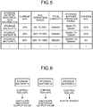
- FIG. 5 is a diagram illustrating an example of the storage battery DB in a state in which the control SOC is registered in the first embodiment.
- the current SOC of "20%” is at a half ratio position of the SOC operation range of "0% to 40%”, and thus the calculation unit 103 calculates the control SOC of the storage battery A as 50%.
- the current SOC of "30%” is at a quarter ratio position of the SOC operation range of "20% to 60%”, and thus the calculation unit 103 calculates the control SOC of the storage battery B as 25%.
- the current SOC of "60%” is at a lower limit position of the SOC operation range of "60% to 100%", and thus the calculation unit 103 calculates the control SOC of the storage battery C as 0%.
- FIG. 6 is a diagram illustrating an example of the case of giving a command of a discharge output value to a storage battery 30 in the first embodiment.
- FIG. 6 illustrates an example corresponding to FIG. 5 .
- the control SOC of the storage battery A is 50%
- the control SOC of the storage battery B is 25%
- the control SOC of the storage battery C is 0%.
- the control SOC of the storage battery C is not in the SOC operation range, and thus the generation unit 105 excludes the storage battery C from the calculation target of the discharge output value.
- the storage battery A has a margin greater than that of the storage battery B. Accordingly, the generation unit 105 calculates a discharge output value for the storage battery A which is greater than a discharge output value for the storage battery B.
- FIG. 7 is a diagram illustrating another example of the storage battery DB in a state in which the control SOC is registered in the first embodiment.
- the current SOC of "40%” is at an upper limit position of the SOC operation range of "0% to 40%", and thus the calculation unit 103 calculates the control SOC of the storage battery A as 100%.
- the current SOC of "40%” is at a half ratio position of the SOC operation range of "20% to 60%”, and thus the calculation unit 103 calculates the control SOC of the storage battery B as 50%.
- the current SOC of "60%” is at a lower limit position of the SOC operation range of "60% to 100%", and thus the calculation unit 103 calculates the control SOC of the storage battery C as 0%.
- FIG. 8 is a diagram illustrating an example of the case of giving a command of a charge output value to the storage battery 30 in the first embodiment.
- FIG. 8 illustrates an example corresponding to FIG. 7 .
- the control SOC of the storage battery A is 100%
- the control SOC of the storage battery B is 50%
- the control SOC of the storage battery C is 0%.
- the control SOC of the storage battery A is not in the SOC operation range, and thus the generation unit 105 excludes the storage battery A from the calculation target of the charge output value.
- the storage battery B has a margin greater than that of the storage battery C. Accordingly, the generation unit 105 calculates a charge output value for the storage battery C which is greater than a charge output value for the storage battery B.
- the storage battery control device 100 acquires the control SOC, which corresponds to a position of the current SOC in the SOC operation range, for each of the storage batteries 30, carries out generation and distribution of the charge and discharge output value for each of the storage batteries 30 on the basis of the control SOC, and transmits the charge and discharge output value to the storage battery 30. Accordingly, according to this embodiment, it is possible to conduct generation and distribution of the charge and discharge output value in accordance with the margin of the storage battery 30 in which the SOC operation range is also considered. Accordingly, according to this embodiment, even when simultaneously carrying out charge and discharge control with respect to the storage batteries 30 in which operation ranges of the electricity storage state are different from each other, it is possible to carry out an efficient operation.
- FIG. 9 is a block diagram illustrating an example of a functional configuration of the storage battery control device according to the second embodiment.
- a storage battery control device 900 mainly includes a reception unit 101, a setting unit 902, a calculation unit 903, a determination unit 104, a generation unit 905, a transmission unit 106, and a storage unit 910.
- the function and the configuration of the reception unit 101, the determination unit 104, and the transmission unit 106 are the same as those in the first embodiment.
- the storage unit 910 is a storage medium such as an HDD, an SSD, and a memory, and stores the storage battery DB similar to the first embodiment.
- a first range, a correction charge power upper limit value, and a correction discharge power upper limit are also stored in the storage unit 910.
- the first range is an SOC range for determination of starting correction of the charge and discharge output value by the generation unit 905.
- the correction charge power upper limit is an upper limit during correction of the charge power value by the generation unit 905.
- the correction discharge power upper limit is an upper limit during correction of a discharge power value by the generation unit 905.
- the correction charge power upper limit and the correction discharge power upper limit are examples of a particular upper limit.
- the setting unit 902 registers identification information of the storage battery, the SOC operation range, the total capacity, the storage battery operation range in the storage battery DB. In addition, the setting unit 902 registers the first range, the correction charge power upper limit, and the correction discharge power upper limit in advance. The first range, the correction charge power upper limit, and the correction discharge power upper limit can be set to any value.
- the setting unit 902 allows a user to directly input the SOC range, and sets the SOC range that is input in the storage unit 910 as the first range.
- the setting unit 902 allows the user to input an output time range at a rating output, converts the output time range that is input to the SOC range, and sets the SOC range to the storage unit 910 as the first range.
- the calculation unit 903 reads out the current SOC and the SOC operation range in the storage battery DB from the storage battery DB with respect to each of the plurality of storage batteries 30, and calculates the control SOC on the basis of the current SOC and the SOC operation range which are read out. In addition, the calculation unit 903 adds the control SOC of each of the plurality of storage batteries 30 to calculate a total control SOC.
- the total control SOC is an example of the total control amount.
- the generation unit 905 determines whether or not the total control SOC, which is calculated by the calculation unit 903, is out of the first range that is set in the storage unit 910, and in a case where the total control SOC is out of the first range, the generation unit 905 corrects the charge and discharge output value that is corrected. Specifically, in a case where the total control SOC is greater than the upper limit of the first range, the generation unit 905 determines that the storage battery 30 is to be corrected in a discharge direction (correction discharge), and generates a discharge output value that is corrected. In addition, in a case where the total control SOC is less than the lower limit of the first range, the generation unit 905 determines that the storage battery 30 is to be corrected in a charge direction (correction charge), and generates a charge output value that is corrected.
- the generation unit 905 determines whether or not the correction can be continuously carried out, and in a case where it is determined that the correction can be continuously carried out, the generation unit 905 corrects the charge and discharge output value.
- the generation unit 905 determines whether or not the storage battery 30 is out of order by using SOC of the storage battery information that is received by the reception unit 101, and in a case where the storage battery 30 is out of order, the generation unit 905 determines that the correction cannot be continuously carried out, and in a case where the storage battery 30 is not out of order, the generation unit 905 determines that the correction can be continuously carried out.
- the generation unit 905 corrects the charge power value in a range that is equal to or less than the correction charge power upper limit.
- the generation unit 905 corrects the discharge power value in a range that is equal to or less than the correction discharge power upper limit.
- FIG. 10 is a flowchart illustrating an example of a procedure of the storage battery control process according to the second embodiment. Processes from S11 to S14 are the same as in the first embodiment.
- the calculation unit 903 calculates the control SOC of all of the storage batteries 30 which are control targets, and then adds the control SOC of each of the storage batteries 30 to calculate a total control SOC (S31).
- the following processes from S15 to S18 are repeatedly carried out for each of the storage batteries 30 which are control targets.
- a first storage battery 30 is selected.
- the determination unit 104 determines whether or not the control SOC is in the SOC operation range (S15). In addition, in a case where the control SOC is not in the SOC operation range (No in S15), the process shifts to S18. In a case where the control SOC is in the SOC operation range (Yes in S15), the generation unit 905 determines whether or not the total control SOC is out of a first range (S32).
- the generation unit 905 determines whether or not correction charge and discharge can be continuously carried out (S34). In addition, in a case where it is determined that the correction charge and discharge can be continuously carried out (Yes in S34), the generation unit 905 calculates a charge and discharge output value of the storage battery 30, which is corrected, from the amount of charge and discharge power that is designated by the charge and discharge command, and distributes the charge and discharge output value (S35). That is, in a case where the total control SOC exceeds the upper limit of the first range, the generation unit 905 determines that the correction discharge is to be carried out, and generates and distributes the discharge output value that is corrected.
- the generation unit 905 determines that the correction charge is to be carried out, and generates and distributes the charge output value that is corrected. In addition, the process shifts to S18.
- the correction process in S35 is not carried out.
- the generation unit 905 calculates the charge and discharge output value of the storage battery 30 from the amount of charge and discharge power that is designated by the charge and discharge command, and distributes the charge and discharge output value (S16). In addition, the process shifts to S18 without correction.
- the correction process in S35 is not carried out, and the generation unit 905 calculates the charge and discharge output value of the storage battery 30 from the amount of charge and discharge power that is designated by the charge and discharge command, and distributes the charge and discharge output value (S16). In addition, the process shifts to S18.
- the determination unit 104 determines whether or not the process from S15 to S35 is completed with respect to all of the storage batteries 30 which are control targets (S18). In addition, in a case where the processes from S15 to S35 with respect to all of the storage batteries 30 which are control targets are not completed (No in S18), the processes from S15 to S35 are repeatedly carried out.
- the transmission unit 106 transmits the charge and discharge output value, which is generated by the generation unit 105, to each of the storage batteries 30 (S19).
- the charge and discharge command from the power management device 10 is a charge command
- the amount of charge power instructed by the charge command is 100 kW, and 50 kW, 30 kW, and 20 kW are distributed to three storage batteries A, B, and C on the basis of each control SOC.
- the generation unit 905 when a correction charge power upper limit is set to 30 kW, with regard to the charge output value that is corrected, the generation unit 905 generates 70 kW obtained by subtracting 30 kW from 100 kW, which is the amount of charge power of the charge command, as the charge output value that is corrected.
- the generation unit 905 distributes the charge output value of 70 kW, which is corrected, to the three storage batteries A, B, and C, for example, like 40 kW, 20 kW, and 10 kW on the basis of each control SOC.
- the charge and discharge command from the power management device 10 is a discharge command, and the amount of discharge power instructed by the discharge command is 100 kW, and for example, 50 kW, 30 kW, and 20 kW are distributed to the three storage batteries A, B, and C on the basis of each control SOC.
- the generation unit 905 when a correction discharge power upper limit is set to 20 kW, with regard to the discharge output value that is corrected, the generation unit 905 generates 120 kW obtained by adding 20 kW to 100 kW, which is the amount of discharge power of the discharge command, as the discharge output value that is corrected.
- the generation unit 905 distributes the discharge output value of 120 kW, which is corrected, to the three storage batteries A, B, and C, for example, like 50 kW, 40 kW, and 30 kW on the basis of each control SOC.
- the calculation unit 903 calculates the total control SOC obtained by adding the control SOC of the plurality of storage batteries 30, and in a case where the total control SOC is out of the first range, the generation unit 905 generates the charge and discharge output value that is corrected. Accordingly, according to this embodiment, even in a case where storage batteries in which the operation ranges of the electricity storage state are different from each other are simultaneously subjected to charge and discharge control, it is possible to carry out an efficient operation in a more accurate manner.
- the generation unit 905 generates the charge and discharge output value, which is corrected, on the basis of the correction charge power upper limit and the correction discharge power upper limit. Accordingly, according to this embodiment, there is no adverse effect on a variation in demand, and thus it is possible to carry out the correction charge and the correction discharge of the storage battery 30.
- the generation unit 905 in the case of the correction charge, the generation unit 905 generates the charge output value, which is corrected, by subtracting the correction charge power upper limit from the amount of charge power of the charge command.
- the generation unit 905 in the case of the correction discharge, the generation unit 905 generates the discharge output value, which is corrected, by adding the correction discharge power upper limit to the amount of discharge power of the discharge command. Accordingly, in this example, the charge and discharge power value, which is corrected and is generated for correction of SOC of the storage battery 30 in a charge direction or a discharge direction, does not extremely increase.
- the calculation unit 903 calculates the total control SOC obtained by adding the control SOC of each of the plurality of storage batteries 30, and the generation unit 905 determines whether or not the total control SOC is in the first range for determination of whether or not the correction charge and the correction discharge are necessary to be carried out. Accordingly, in this example, the storage battery control device 100 does not grasp a current state of the storage battery 30 for each storage battery, and collectively grasps the state of the entirety of the storage batteries 30 under management of the storage battery control device 100, and thus it is possible to carry out the correction charge or the correction discharge of the storage battery 30.
- the plurality of storage batteries 30 do not simultaneously initiate the correction charge or the correction discharge at a moment at which a system frequency reaches in a constant range, and the like, and thus it is possible to prevent a situation in which carrying out and stoppage of the correction charge or the correction discharge repetitively occur. Accordingly, according to this embodiment, the correction charge and the correction discharge of the storage battery 30 are carried out from a viewpoint which takes much into account, and thus system stabilization control does not become complex. As a result, according to this embodiment, the correction charge and the correction discharge of the storage battery 30 do not cause a frequency variation, and the charge and discharge control by the storage battery 30 can contribute to stabilization of the power system 20.
- a plurality of the SOC operation ranges are set for each storage battery 30, and the storage battery control device selects one SOC range from the plurality of SOC operation ranges, and generates the charge and discharge power value.
- FIG. 11 is a block diagram illustrating an example of a function configuration of the storage battery control device according to the third embodiment.
- a storage battery control device 1100 mainly includes a reception unit 1101, a setting unit 102, a calculation unit 1103, a determination unit 104, a generation unit 105, a transmission unit 106, and a storage unit 1110.
- the function and the configuration of the setting unit 102, the determination unit 104, the generation unit 105, and the transmission unit 106 are the same as those in the first embodiment.
- the storage unit 1110 is a storage medium such as an HDD, an SSD, and a memory.
- the storage battery DB and a second range are stored in the storage unit 1110.
- the second range is a range for determined of whether or not the following system information is in a specified range.
- the second range is set by the setting unit 102.
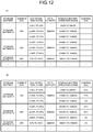
- FIG. 12 is a diagram illustrating an example of the storage battery DB according to the third embodiment. (a) of FIG. 12 illustrates an example of the storage battery DB before calculation of the control SOC, and (b) of FIG. 12 illustrates an example of the storage battery DB after calculation of the control SOC.
- the plurality of SOC operation ranges are determined for each of the plurality of storage batteries 30.
- the plurality of SOC operation ranges, which are determined, include an SOC operation range of a normal operation, an SOC operation range of an emergency operation, an SOC operation range of an economical operation, and the like.
- the SOC operation range of the normal operation is an SOC operation range of the storage battery 30 that is applied during a normal operation of the storage battery 30.
- the SOC operation range of the emergency operation is an SOC operation range that is applied during an operation of the storage battery 30 in a case where it is necessary to output at the sacrifice of charge and discharge efficiency in case of emergency.
- the SOC operation range of the economical operation is an SOC operation range that is applied during an operation of the storage battery 30 in a case where it is necessary to consider the charge and discharge efficiency to the maximum.
- the plurality of SOC operation ranges are not limited thereto. For example, an SOC operation range during a load frequency control operation may be determined.
- the reception unit 1101 receives a charge and discharge command from the power management device 10, and receives storage battery information from the storage battery 30.
- the reception unit 1101 in this embodiment further receives an instruction for selection of the SOC operation range from the power management device 10.
- the instruction for selection of the SOC operation range is an instruction for selection of which SOC operation range for each of the storage batteries 30.
- the reception unit 1101 receives system information from the power system 20 or the power management device 10.
- the system information is information relating to a state of the power system 20, and examples thereof include a system frequency, a bus line voltage, a main line power flow, and the like.
- the system information is not limited thereto as long as the state of the power system 20 is indicated.
- the calculation unit 1103 calculates the control SOC with respect to each of the plurality of storage batteries 30 on the basis of the current SOC, and the SOC operation range that is designated by the instruction for selection. In addition, the calculation unit 1103 determines whether or not the system information received by the reception unit 1101 is out of the second range. In a case where the system information is out of the second range, the calculation unit 1103 selects the SOC operation range of the emergency operation among the plurality of SOC operation ranges, and calculates the control SOC with respect to each of the plurality of storage batteries 30 on the basis of the current SOC and the SOC operation range of the emergency operation which is selected.
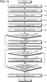
- FIG. 13 is a flowchart illustrating an example of a procedure of the storage battery control process according to the third embodiment. Processes from S11 to S13 are the same as in the first embodiment.
- the reception unit 1101 receives an instruction for selection of the SOC operation range from the power management device 10 (S51).
- the calculation unit 1103 selects the storage battery 30 that is designated by the instruction for selection which is received, and the SOC operation range that is instructed for selection with respect to the storage battery (S52).
- the reception unit 1101 receives system information from the power system 20 or the power management device 10 (S53).
- the calculation unit 1103 determines whether or not the system information that is received is out of the second range (S54). In addition, in a case where the system information is out of the second range (Yes in S54), the calculation unit 1103 selects the SOC operation range during the emergency operation with respect to all of the storage batteries 30 (S55). On the other hand, in a case where the system information is not out of the second range (No in S54), the selection of the SOC operation range during the emergency operation in S55 is not carried out.
- calculation unit 1103 calculates the control SOC for each of the storage batteries 30 on the basis of the SOC operation range that is selected, and the current SOC (S14).
- the subsequent processes are the same as in the first embodiment.
- the plurality of SOC operation ranges are set, and the calculation unit 1103 selects the SOC operation range in accordance with the instruction for selection and the system information, thereby calculating the control SOC. Accordingly, in this example, it is possible to select the plurality of SOC operation ranges in accordance with the operation types such as in case of emergency, during a normal operation, during an economical operation, a load frequency control operation, and the like in a switchable manner, and thus it is possible to operate the storage battery control system in a more flexible manner.
- FIG. 14 is a block diagram illustrating an example of a function configuration of a storage battery control device according to the fourth embodiment.
- a storage battery control device 1400 according to this embodiment mainly includes a reception unit 101, a setting unit 102, an operation range correction unit 1401, a calculation unit 1403, a determination unit 104, a generation unit 105, a transmission unit 106, and a storage unit 1410.
- the function and the configuration of the reception unit 101, the setting unit 102, the determination unit 104, the generation unit 105, and the transmission unit 106 are the same as those in the first embodiment.
- the storage unit 1410 is a storage medium such as an HDD, an SSD, and a memory.
- an SOC-charge and discharge efficiency table, and a third range are stored in the storage unit 1410.
- the third range is a value that can be used for the following determination of charge and discharge efficiency.
- the third range is set by the setting unit 102.
- the SOC-charge and discharge efficiency table is a table in which a relationship between SOC and the charge and discharge efficiency is determined, and is set in advance by the setting unit 102 in accordance with statistics.
- FIG. 15 is a diagram illustrating an example of the SOC-charge and discharge efficiency table of the fourth embodiment. As illustrated in FIG. 15 , in the SOC-charge and discharge efficiency table, the SOC and the charge and discharge efficiency are registered in correspondence with each other.
- the operation range correction unit 1401 calculates the charge and discharge efficiency from the current SOC in the storage battery information that is received by the reception unit 101. Specifically, the operation range correction unit 1401 refers to the SOC-charge and discharge efficiency table, and acquires charge and discharge efficiency corresponding to the current SOC. In addition, the operation range correction unit 1401 calculates charge and discharge efficiency at the upper limit and the lower limit of the SOC operation range from the charge and discharge efficiency that is obtained, and determines whether or not the charge and discharge efficiency that is calculated is out of the third range. In a case where the charge and discharge efficiency that is calculated is out of the third range, the operation range correction unit 1401 corrects the SOC operation range in order for the charge and discharge efficiency that is calculated to be in the third range.
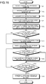
- FIG. 16 is a flowchart illustrating an example of a procedure of the storage battery control process according to the fourth embodiment. Processes from S11 to S13 are the same as in the first embodiment.
- the SOC operation range correction unit 1401 refers to the SOC-charge and discharge efficiency table, and calculates charge and discharge efficiency corresponding to the current SOC (S71).
- the operation range correction unit 1401 calculates charge and discharge efficiency at the upper limit and the lower limit of the SOC operation range from the charge and discharge efficiency that is obtained (S72).
- the SOC operation range correction unit 1401 determines whether or not the charge and discharge efficiency, which is calculated in S72, is out of the third range (S73).
- the operation range correction unit 1401 corrects the SOC operation range in order for the charge and discharge efficiency that is calculated to be in the third range (S74).
- the correction of the SOC operation range is not carried out.
- calculation unit 1403 calculates the control SOC by using the SOC operation range for each of the storage batteries 30 (S14).
- the subsequent processes are the same as in the first embodiment.
- the operation range correction unit 1401 calculates the charge and discharge efficiency from the current SOC in the storage battery information that is received by the reception unit 101, and calculates the charge and discharge efficiency at the upper limit and the lower limit of the SOC operation range. In a case where the charge and discharge efficiency that is calculated is out of the third range, the operation range correction unit 1401 corrects the SOC operation range in order for the charge and discharge efficiency that is calculated to be in the third range. Accordingly, according to this embodiment, even when a variation in characteristics of the storage battery 30 occurs due to deterioration with the passage of time, and the like, it is possible to carry out charge and discharge control of the storage battery 30 in correspondence with the variation in the characteristics.
- the storage battery control devices 100, 900, 1100, and 1400 of the above-described embodiments include a control device such as a CPU, a storage device such as a read only memory (ROM) and a ramdom access memory (RAM), an external storage device such as an HDD and a CD drive, a display device such as a display device, and an input device such as a keyboard and a mouse, and thus has a hardware configuration using a computer.
- a control device such as a CPU
- a storage device such as a read only memory (ROM) and a ramdom access memory (RAM)
- an external storage device such as an HDD and a CD drive
- a display device such as a display device
- an input device such as a keyboard and a mouse
- the storage battery control process which is executed by the storage battery control devices 100, 900, 1100, and 1400 of the above-described embodiments, may be realized by software, or may be realized by hardware such as an electronic circuit.
- a storage battery control program which is executed by the storage battery control devices 100, 900, 1100, and 1400 of the above-described embodiments, is recorded in a computer readable recording medium such as a CD-ROM, an FD (flexible disk), a CD-R, and a digital versatile disk (DVD) as a file in an installation type or execution type, and is provided as a computer program product.
- a computer readable recording medium such as a CD-ROM, an FD (flexible disk), a CD-R, and a digital versatile disk (DVD)
- the storage battery control program which is executed by the storage battery control devices 100, 900, 1100, and 1400 of the above-described embodiments, may be configured to be stored in a computer that is connected to a network such as the Internet, and to be downloaded for provision as a computer program product through the network.
- the storage battery program which is executed by the storage battery control devices 100, 900, 1100, and 1400 of the above-described embodiments, may be configured to be provided and distributed as a computer program product through a network such as the Internet.
- the storage battery control program which is executed by the storage battery control devices 100, 900, 1100, and 1400 of the above-described embodiments, may be configured to be incorporated with a ROM and the like in advance and to be provided as a computer program product.
- the storage battery control program which is executed by the storage battery control devices 100, 900, 1100, and 1400 of the above-described embodiments, has a module configuration including the above-described respective units (the reception unit, the setting unit, the calculation unit, the determination unit, the generation unit, the transmission unit, and the operation range correction unit).
- a CPU processor
- the respective units are loaded on the RAM, and thus the reception unit, the setting unit, the calculation unit, the determination unit, the generation unit, the transmission unit, and the SOC operation range correction unit are generated on the RAM.
Landscapes
- Engineering & Computer Science (AREA)
- Power Engineering (AREA)
- Manufacturing & Machinery (AREA)
- Chemical & Material Sciences (AREA)
- Chemical Kinetics & Catalysis (AREA)
- Electrochemistry (AREA)
- General Chemical & Material Sciences (AREA)
- Charge And Discharge Circuits For Batteries Or The Like (AREA)
- Supply And Distribution Of Alternating Current (AREA)
- Secondary Cells (AREA)
- Remote Monitoring And Control Of Power-Distribution Networks (AREA)
Abstract
Description
- Embodiments of the invention relate to a storage battery control device, and a storage battery control method.
- Recently, natural energy such as sunlight power generation and wind power generation has been introduced in an active manner, and the natural energy has been utilized even by general customers by installation of a solar panel. A power generation apparatus using the natural energy depends on a meteorological phenomenon, weather, and the like, and thus there is a case where a power system may be unstable.
- To solve instability relating to the power system, there is known a technology in which a storage battery is connected to the power system, and a variation in power generation due to natural energy and the like is compensated through output adjustment by charging or discharging of the storage battery. As this technology, for example, a load frequency control (LFC), in which output adjustment in accordance with the demand for electric power is known. In LFC, a raising command for instruction of an increase in an output, and a lowering command for instruction of a decrease in the output are transmitted to an electric power generator, thereby constantly maintaining a frequency of a system, and a link line power flow.
- Typically, in LFC, the raising command and the lowering command are controlled to be entirely uniform. However, in the case of transmitting the command for output adjustment in LFC to the storage battery, even when the raising command and the lowering command are set to the same amount, the power storage residual amount of the storage battery decreases due to a charge and discharge loss in the storage battery, and thus, finally, it is difficult to cope with the raising command (discharge command for the storage battery). In addition, in contrast, even in a case where an amount of charge and an amount of discharge are set to the same as each other through the whole, a command value is inclined to a charge direction at a certain time zone, and thus charge is carried out to the capacity upper limit of the storage battery, and a chargeable electric power amount may be zero.
- In this regard, in the related art, there is known a technology in which an operation range, which is a dynamic range of state of charge (SOC) for each storage battery, is limited, and charge and discharge of the storage battery are controlled in the operation range of SOC, or storage battery information including a charge performance and a battery residual amount of a plurality of storage batteries is acquired for a constant time interval, and the charge and discharge are controlled on the basis of the storage battery information.
-
- Patent Literature 1:
Japanese Patent Application Laid-open No. 2013-106372 - Patent Literature 2:
Japanese Patent Application Laid-open No. 2014-233096 - However, in the related art, in a case simultaneously operating storage batteries in which operation ranges of SOC are different from each other, it is necessary to examine a process or a rule in accordance with the respective operation ranges, and thus application to a system, in which a large number of storage batteries are necessary, is difficult, and thus inefficient operation may be carried out.
- A storage battery control device in embodiments comprises a first reception unit, a second reception unit, a calculation unit, a generation unit, and a transmission unit. The first reception unit receives a charge and discharge command from a power management device. The second reception unit receives a current electricity storage state from each of a plurality of storage batteries. The calculation unit calculates a control amount, which indicates a ratio of the current electricity storage state in an operation range, with respect to each of the plurality of storage batteries on the basis of the current electricity storage state and the operation range of the electricity storage state. The generation unit generates a charge and discharge output value, which is an output value of charge and discharge for the each of the plurality of storage batteries, on the basis of the control amount that is calculated for each of the plurality of storage batteries, and the charge and discharge command that is received. The transmission unit transmits the charge and discharge output value, which is generated, to each of the plurality of storage batteries.
-
-
FIG. 1 is a diagram illustrating an example of an entire configuration of a storage battery control system according to a first embodiment. -
FIG. 2 is a block diagram illustrating an example of a functional configuration of a storagebattery control device 100 according to the first embodiment. -
FIG. 3 is a diagram illustrating an example of a storage battery DB according to the first embodiment. -
FIG. 4 is a flowchart illustrating an example of a procedure of a storage battery control process according to the first embodiment. -
FIG. 5 is a diagram illustrating an example of a storage battery DB in a state in which control SOC is registered in the first embodiment. -
FIG. 6 is a diagram illustrating an example of the case of giving a command of a discharge output value to astorage battery 30 in the first embodiment. -
FIG. 7 is a diagram illustrating another example of the storage battery DB in a state in which the control SOC is registered in the first embodiment. -
FIG. 8 is a diagram illustrating an example of the case of giving a command of a charge output value to thestorage battery 30 in the first embodiment. -
FIG. 9 is a block diagram illustrating an example of a functional configuration of a storage battery control device according to a second embodiment. -
FIG. 10 is a flowchart illustrating an example of a procedure of a storage battery control process according to the second embodiment. -
FIG. 11 is a block diagram illustrating an example of a functional configuration of a storage battery control device according to third embodiment. -
FIG. 12 is a diagram illustrating an example of a storage battery DB according to the third embodiment. -
FIG. 13 is a flowchart illustrating an example of a procedure of a storage battery control process according to the third embodiment. -
FIG. 14 is a block diagram illustrating an example of a functional configuration of a storage battery control device according to a fourth embodiment. -
FIG. 15 is a diagram illustrating an example of an SOC-charge and discharge efficiency table according to the fourth embodiment. -
FIG. 16 is a flowchart illustrating an example of a procedure of a storage battery control process according to the fourth embodiment. - Hereinafter, embodiments will be described with reference to the accompanying drawings.
-
FIG. 1 is a diagram illustrating an example of an entire configuration of a storage battery control system according to a first embodiment. As illustrated inFIG. 1 , a storagebattery control system 1 according to this embodiment includes a configuration in which apower management device 10, a plurality of storagebattery control devices 100, and a plurality ofstorage batteries 30 are connected to apower system 20. The plurality ofstorage batteries 30, which are control targets, are connected to one storagebattery control device 100. On the other hand, a thermoelectric power plant, a hydroelectric power plant, and the like are also connected to thepower system 20, but these plants and the like are not illustrated in the diagram ofFIG. 1 . - The
power management device 10 is a device that manages stabilization of thepower system 20. Thepower management device 10 is embedded, for example, in a computer and the like which are installed in a central power feed command center and the like. Thepower management device 10 transmits a charge and discharge command, which indicates an amount of charge and discharge power of a storage battery to each of the storagebattery control devices 100. The charge and discharge command is also referred to as an upper-layer command. - Here, examples of the charge and discharge command include a discharge command (raising command) and a charge command (lowering command). The discharge command is a command including an instruction for an increase in an output, that is, an instruction for discharge of the
storage batteries 30, and an amount of discharge power. The charge command is a command including an instruction for a decrease in an output, that is, an instruction for charge of thestorage batteries 30, and an amount of charge power. Here, the amount of discharge power, and the amount of charge power are collectively called an amount of charge and discharge power. - Each of the plurality of
storage batteries 30 is formed by connecting a plurality of cells including an electrode and an electrolyte. For example, therespective storage batteries 30 can be configured as a lithium ion storage battery, a lead storage battery, a nickel-hydrogen storage battery, a sodium-sulfur storage battery, and the like, but there is no limitation thereto. In addition, therespective storage batteries 30 may include a sensor that detects an electricity storage state (SOC) indicating an amount of charge, and the like. - The storage
battery control device 100 manages an amount of charge of each of thestorage batteries 30 by controlling the charge and discharge of one or the plurality of thestorage batteries 30 which are control targets.FIG. 2 is a block diagram illustrating an example of a functional configuration of the storagebattery control device 100 according to the first embodiment. As illustrated inFIG. 2 , the storagebattery control device 100 according to this embodiment mainly includes areception unit 101, asetting unit 102, acalculation unit 103, adetermination unit 104, ageneration unit 105, atransmission unit 106, and astorage unit 110. - The
reception unit 101 receives a charge and discharge command from thepower management device 10. In addition, thereception unit 101 receives storage battery information from each of thestorage batteries 30. Here, the storage battery information is data including a current electricity storage state (SOC). Thereception unit 101 is an example of a first reception unit and a second reception unit. - The
storage unit 110 is a storage medium such as a hard disk drive (HDD), a solid state drive (SSD), and a memory. A storage battery database (hereinafter, referred to as a "storage battery DB") is stored in thestorage unit 110. - The storage battery DB is a database in which information relating to the
storage battery 30 that is a control target is registered.FIG. 3 is a diagram illustrating an example of the storage battery DB according to the first embodiment. As illustrated inFIG. 3 , storage battery identification information, the current SOC, an SOC operation range, a total capacity, a storage battery operation range, and a control SOC are registered in the storage battery DB of this embodiment in correspondence with each other. - Here, in the example illustrated in
FIG. 3 , three storage batteries A, B, and C, which are connected to the central storagebattery control device 100 inFIG. 1 and are controlled, are illustrated as an example. However, there is no limitation thereto. This is true of a plurality ofother storage batteries 30. - The storage battery identification information is information for identification of the
storage battery 30 that is a control target, and corresponds to, for example, a name of the storage battery, and the like. The current SOC is included in the storage battery information that is received by thereception unit 101, is a current SOC of thestorage battery 30, and is registered in the storage battery DB by thereception unit 101. - The SOC operation range is a range of SOC in the case of operating the
storage battery 30, and is indicated by the upper limit and the lower limit of SOC. The total capacity is an amount of power that can be output from thestorage battery 30, and a unit thereof is kWh. The storage battery operation range is a range of an amount of power that corresponds to the SOC operation range. Details of the control SOC will be described later. - Returning to
FIG. 2 , thesetting unit 102 sets and registers the storage battery identification information, the SOC operation range, the total capacity, and the storage battery operation range in the storage battery DB. Thesetting unit 102 carries out the registration of the plurality of pieces of information in the storage battery DB in advance on the basis of input data from a user, and the like. - The
calculation unit 103 reads out the current SOC and the SOC operation range in the storage battery DB from the storage battery DB with respect to each of the plurality ofstorage batteries 30, and calculates the control SOC on the basis of the current SOC and the SOC operation range which are read out. The control SOC is a ratio of the current SOC in the SOC operation range. Thecalculation unit 103 registers the control SOC, which is calculated, in the storage battery DB. The control SOC is an example of the control amount. - Here, the reason for calculating the control SOC will be described. In the example illustrated in
FIG. 3 , SOC operation ranges of thestorage batteries 30 which are different in characteristics are indicated. In the case of generating a charge and discharge output value of thestorage batteries 30 with focus given to the control SOC, in the example inFIG. 3 , the current SOC of the storage battery C is greater than the current SOC of the storage batteries A and B, and thus the amount of charge of the storage battery C is the greatest. Accordingly, the storage battery control device in the related art distributes the charge and discharge output value to the respective storage batteries A, B, and C in such a manner that the charge and discharge output value to be greatest for the storage battery C. - However, when referring to SOC operation range, the current SOC of "60%" of the storage battery C reaches the lower limit of the SOC operation range of "60% to 100%", and thus discharge cannot be carried out any more. Therefore, even when the storage battery control device provides a discharge command to the storage battery C in combination with a discharge output value, the storage battery C is less likely to operate in accordance with the command.
- In addition, when comparing the SOC of the storage battery A and the current SOC of the storage battery B with each other, the current SOC is greater on a storage battery B side, and thus the storage battery B has a more margin for discharge. Accordingly, much discharge output value is distributed to the storage battery B by the storage battery control device of the related art. However, when referring to the SOC operation range, in the case of the storage battery A, the current SOC of "20%" is approximately the center of the SOC operation range of "0% to 40%", and in the case of the storage battery B, the current SOC of "30%" is closer to the lower limit of "20%" of the SOC operation range of "20% to 60%". Therefore, the storage battery A has a more margin. Accordingly, when the storage battery control device distributes a more charge and discharge output value to the storage battery A, this leading to a more efficient operation capable of utilizing the margin of the respective storage batteries to the maximum.
- As described above, in the case of distributing the charge and discharge output value with reference to only the current SOC, this case may not lead to an operation with efficiency in which the margin of the storage batteries is sufficiently reflected. Therefore, in this embodiment, the
calculation unit 103 makes a request for a ratio of the current SOC, which indicates where the current SOC locates in the SOC operation range, in the SOC operation range as the control SOC. The following generation unit distributes (generates) the charge and discharge output value to each of thestorage batteries 30 on the basis of the control SOC. Accordingly, according to this embodiment, it is possible to realize an operation with efficiency in which the margin of therespective storage batteries 30 is sufficiently reflected. - The
determination unit 104 determines whether or not the control SOC is in the SOC operation range with respect to each of the plurality ofstorage batteries 30. - With respect to the
respective storage batteries 30 in which the control SOC is determined by thedetermination unit 104 to be in the SOC operation range, thegeneration unit 105 generates and distributes the charge and discharge output value for each of the plurality ofstorage batteries 30 on the basis of the control SOC that is calculated by thecalculation unit 103, and the amount of charge and discharge power of the charge and discharge command which is received. The charge and discharge output value is an output value of charge and discharge, and includes a discharge output value that gives an instruction to thestorage battery 30 to discharge, and a charge output value that gives an instruction to thestorage battery 30 to charge. Here, the discharge output value and the charge output value are collectively called a charge and discharge output value. - The
transmission unit 106 transmits the charge and discharge output value for each of thestorage batteries 30, which is generated by thegeneration unit 105, to each of thestorage batteries 30. - Description will be given of a storage battery control process of this embodiment which is configured as described above.
FIG. 4 is a flowchart illustrating an example of a procedure of the storage battery control process according to the first embodiment. First, thereception unit 101 receives a charge and discharge command from the power management device 10 (S11). In addition, thereception unit 101 receives storage battery information including the current SOC from each of the plurality of storage batteries 30 (S12). Thereception unit 101 acquires the current SOC from the storage battery information that is received, and registers the acquired current SOC as a current SOC, which corresponds to identification information of thestorage battery 30 that is a transmission source, in the storage battery DB of thestorage unit 110. - Next, the
calculation unit 103 acquires the SOC operation range of each of the plurality ofstorage batteries 30, which are control targets, from the storage battery DB (S13). In addition, thecalculation unit 103 calculates the control SOC from the SOC operation range and the current SOC which are acquired for each of the storage batteries 30 (S14). - The following processes from S15 to S18 are repeatedly carried out with respect to each of the
storage batteries 30 which are control targets. First, afirst storage battery 30 is selected. Thedetermination unit 104 determines whether or not the control SOC is in the SOC operation range (S15). In addition, in a case where the control SOC is in the SOC operation range (Yes in S15), thegeneration unit 105 calculates the charge and discharge output value of thestorage battery 30 from the amount of charge and discharge power that is designated by the charge and discharge command, and distributes the charge and discharge output value (S16). Specifically, thegeneration unit 105 calculates a provisional value corresponding to the control SOC from the amount of charge and discharge power, and in a case where the provisional value is equal to or less than a total rating output of thestorage battery 30, the provisional value is set as the charge and discharge output value. - In a case where it is determined in S15 that the control SOC is not in the SOC operation range (No in S15), calculation of the charge and discharge output value in S16 is not carried out with respect to the
storage battery 30 that is selected. - Next, the
determination unit 104 determines whether or not the processes in S15 and S16 are completed with respect to all of thestorage batteries 30 which are control targets (S18). In addition, in a case where the processes S15 and S16 are not completed with respect to all of thestorage batteries 30 which are control targets (No in S18), the processes of S15 and S16 are repeatedly carried out. - On the other hand, in a case where the processes of S15 and S16 are completed with respect to all of the
storage batteries 30 which are control targets (Yes in S18), thetransmission unit 106 transmits the charge and discharge output value, which is generated by thegeneration unit 105, to each of the storage batteries 30 (S19). - Hereinafter, description will be given of generation of the charge and discharge output value as an example.
FIG. 5 is a diagram illustrating an example of the storage battery DB in a state in which the control SOC is registered in the first embodiment. As illustrated inFIG. 5 , in the storage battery A, the current SOC of "20%" is at a half ratio position of the SOC operation range of "0% to 40%", and thus thecalculation unit 103 calculates the control SOC of the storage battery A as 50%. In addition, as illustrated inFIG. 5 , in the storage battery B, the current SOC of "30%" is at a quarter ratio position of the SOC operation range of "20% to 60%", and thus thecalculation unit 103 calculates the control SOC of the storage battery B as 25%. In addition, as illustrated inFIG. 5 , in the storage battery C, the current SOC of "60%" is at a lower limit position of the SOC operation range of "60% to 100%", and thus thecalculation unit 103 calculates the control SOC of the storage battery C as 0%. -
FIG. 6 is a diagram illustrating an example of the case of giving a command of a discharge output value to astorage battery 30 in the first embodiment.FIG. 6 illustrates an example corresponding toFIG. 5 . As illustrated inFIGS. 5 and 6 , the control SOC of the storage battery A is 50%, the control SOC of the storage battery B is 25%, and the control SOC of the storage battery C is 0%. The control SOC of the storage battery C is not in the SOC operation range, and thus thegeneration unit 105 excludes the storage battery C from the calculation target of the discharge output value. - In addition, according to the control SOC, the storage battery A has a margin greater than that of the storage battery B. Accordingly, the
generation unit 105 calculates a discharge output value for the storage battery A which is greater than a discharge output value for the storage battery B. - In addition,
FIG. 7 is a diagram illustrating another example of the storage battery DB in a state in which the control SOC is registered in the first embodiment. As illustrate dinFIG. 7 , in the storage battery A, the current SOC of "40%" is at an upper limit position of the SOC operation range of "0% to 40%", and thus thecalculation unit 103 calculates the control SOC of the storage battery A as 100%. In addition, as illustrated inFIG. 7 , in the storage battery B, the current SOC of "40%" is at a half ratio position of the SOC operation range of "20% to 60%", and thus thecalculation unit 103 calculates the control SOC of the storage battery B as 50%. In addition, as illustrated inFIG. 7 , in the storage battery C, the current SOC of "60%" is at a lower limit position of the SOC operation range of "60% to 100%", and thus thecalculation unit 103 calculates the control SOC of the storage battery C as 0%. -
FIG. 8 is a diagram illustrating an example of the case of giving a command of a charge output value to thestorage battery 30 in the first embodiment.FIG. 8 illustrates an example corresponding toFIG. 7 . As illustrated inFIGS. 7 and 8 , the control SOC of the storage battery A is 100%, the control SOC of the storage battery B is 50%, and the control SOC of the storage battery C is 0%. The control SOC of the storage battery A is not in the SOC operation range, and thus thegeneration unit 105 excludes the storage battery A from the calculation target of the charge output value. - In addition, according to the control SOC, the storage battery B has a margin greater than that of the storage battery C. Accordingly, the
generation unit 105 calculates a charge output value for the storage battery C which is greater than a charge output value for the storage battery B. - As described above, according to this embodiment, the storage
battery control device 100 acquires the control SOC, which corresponds to a position of the current SOC in the SOC operation range, for each of thestorage batteries 30, carries out generation and distribution of the charge and discharge output value for each of thestorage batteries 30 on the basis of the control SOC, and transmits the charge and discharge output value to thestorage battery 30. Accordingly, according to this embodiment, it is possible to conduct generation and distribution of the charge and discharge output value in accordance with the margin of thestorage battery 30 in which the SOC operation range is also considered. Accordingly, according to this embodiment, even when simultaneously carrying out charge and discharge control with respect to thestorage batteries 30 in which operation ranges of the electricity storage state are different from each other, it is possible to carry out an efficient operation. - In a second embodiment, correction of the charge and discharge output value is carried out. The entire configuration of a storage battery control system in the second embodiment is the same as in the first embodiment illustrated in
FIG. 1 .FIG. 9 is a block diagram illustrating an example of a functional configuration of the storage battery control device according to the second embodiment. - As illustrated in
FIG. 9 , a storagebattery control device 900 according to this embodiment mainly includes areception unit 101, asetting unit 902, acalculation unit 903, adetermination unit 104, ageneration unit 905, atransmission unit 106, and astorage unit 910. Here, the function and the configuration of thereception unit 101, thedetermination unit 104, and thetransmission unit 106 are the same as those in the first embodiment. - The
storage unit 910 is a storage medium such as an HDD, an SSD, and a memory, and stores the storage battery DB similar to the first embodiment. In the second embodiment, a first range, a correction charge power upper limit value, and a correction discharge power upper limit are also stored in thestorage unit 910. - The first range is an SOC range for determination of starting correction of the charge and discharge output value by the
generation unit 905. The correction charge power upper limit is an upper limit during correction of the charge power value by thegeneration unit 905. The correction discharge power upper limit is an upper limit during correction of a discharge power value by thegeneration unit 905. The correction charge power upper limit and the correction discharge power upper limit are examples of a particular upper limit. - As is the case with the first embodiment, the
setting unit 902 registers identification information of the storage battery, the SOC operation range, the total capacity, the storage battery operation range in the storage battery DB. In addition, thesetting unit 902 registers the first range, the correction charge power upper limit, and the correction discharge power upper limit in advance. The first range, the correction charge power upper limit, and the correction discharge power upper limit can be set to any value. Thesetting unit 902 allows a user to directly input the SOC range, and sets the SOC range that is input in thestorage unit 910 as the first range. In addition to this, it is possible to configure thesetting unit 902 in such a manner that thesetting unit 902 allows the user to input an output time range at a rating output, converts the output time range that is input to the SOC range, and sets the SOC range to thestorage unit 910 as the first range. - As is the case with the first embodiment, the
calculation unit 903 reads out the current SOC and the SOC operation range in the storage battery DB from the storage battery DB with respect to each of the plurality ofstorage batteries 30, and calculates the control SOC on the basis of the current SOC and the SOC operation range which are read out. In addition, thecalculation unit 903 adds the control SOC of each of the plurality ofstorage batteries 30 to calculate a total control SOC. Here, the total control SOC is an example of the total control amount. - The
generation unit 905 determines whether or not the total control SOC, which is calculated by thecalculation unit 903, is out of the first range that is set in thestorage unit 910, and in a case where the total control SOC is out of the first range, thegeneration unit 905 corrects the charge and discharge output value that is corrected. Specifically, in a case where the total control SOC is greater than the upper limit of the first range, thegeneration unit 905 determines that thestorage battery 30 is to be corrected in a discharge direction (correction discharge), and generates a discharge output value that is corrected. In addition, in a case where the total control SOC is less than the lower limit of the first range, thegeneration unit 905 determines that thestorage battery 30 is to be corrected in a charge direction (correction charge), and generates a charge output value that is corrected. - In a case where the total control SOC is out of the first range, the
generation unit 905 determines whether or not the correction can be continuously carried out, and in a case where it is determined that the correction can be continuously carried out, thegeneration unit 905 corrects the charge and discharge output value. Here, with regard to whether or not the correction can be continuously carried out, thegeneration unit 905 determines whether or not thestorage battery 30 is out of order by using SOC of the storage battery information that is received by thereception unit 101, and in a case where thestorage battery 30 is out of order, thegeneration unit 905 determines that the correction cannot be continuously carried out, and in a case where thestorage battery 30 is not out of order, thegeneration unit 905 determines that the correction can be continuously carried out. In addition, thegeneration unit 905 corrects the charge power value in a range that is equal to or less than the correction charge power upper limit. Thegeneration unit 905 corrects the discharge power value in a range that is equal to or less than the correction discharge power upper limit. - Description will be given of a storage battery control process according to the second embodiment which is configured as described above.
FIG. 10 is a flowchart illustrating an example of a procedure of the storage battery control process according to the second embodiment. Processes from S11 to S14 are the same as in the first embodiment. Thecalculation unit 903 calculates the control SOC of all of thestorage batteries 30 which are control targets, and then adds the control SOC of each of thestorage batteries 30 to calculate a total control SOC (S31). - The following processes from S15 to S18 are repeatedly carried out for each of the
storage batteries 30 which are control targets. First, afirst storage battery 30 is selected. Thedetermination unit 104 determines whether or not the control SOC is in the SOC operation range (S15). In addition, in a case where the control SOC is not in the SOC operation range (No in S15), the process shifts to S18. In a case where the control SOC is in the SOC operation range (Yes in S15), thegeneration unit 905 determines whether or not the total control SOC is out of a first range (S32). - In addition, in a case where the total control SOC is out of the first range (Yes in S32), the
generation unit 905 determines whether or not correction charge and discharge can be continuously carried out (S34). In addition, in a case where it is determined that the correction charge and discharge can be continuously carried out (Yes in S34), thegeneration unit 905 calculates a charge and discharge output value of thestorage battery 30, which is corrected, from the amount of charge and discharge power that is designated by the charge and discharge command, and distributes the charge and discharge output value (S35). That is, in a case where the total control SOC exceeds the upper limit of the first range, thegeneration unit 905 determines that the correction discharge is to be carried out, and generates and distributes the discharge output value that is corrected. In addition, in a case where the total control SOC is less than the lower limit of the first range, thegeneration unit 905 determines that the correction charge is to be carried out, and generates and distributes the charge output value that is corrected. In addition, the process shifts to S18. - In a case where it is determined in S32 that the total control SOC is not out of the first range (No in S32), the correction process in S35 is not carried out. In this case, the
generation unit 905 calculates the charge and discharge output value of thestorage battery 30 from the amount of charge and discharge power that is designated by the charge and discharge command, and distributes the charge and discharge output value (S16). In addition, the process shifts to S18 without correction. - In addition, even in a case where it is determined in S34 that the correction charge and discharge cannot be continuously carried out (No in S34), the correction process in S35 is not carried out, and the
generation unit 905 calculates the charge and discharge output value of thestorage battery 30 from the amount of charge and discharge power that is designated by the charge and discharge command, and distributes the charge and discharge output value (S16). In addition, the process shifts to S18. - In S18, as is the case with the first embodiment, the
determination unit 104 determines whether or not the process from S15 to S35 is completed with respect to all of thestorage batteries 30 which are control targets (S18). In addition, in a case where the processes from S15 to S35 with respect to all of thestorage batteries 30 which are control targets are not completed (No in S18), the processes from S15 to S35 are repeatedly carried out. - On the other hand, in a case where the processes from S15 to S35 are completed with respect to all of the
storage batteries 30 which are control targets (Yes in S18), thetransmission unit 106 transmits the charge and discharge output value, which is generated by thegeneration unit 105, to each of the storage batteries 30 (S19). - Description will be given of a specific example of calculating the charge and discharge output value that is corrected. First, description will be given of the correction charge. It is assumed that the charge and discharge command from the
power management device 10 is a charge command, and the amount of charge power instructed by the charge command is 100 kW, and 50 kW, 30 kW, and 20 kW are distributed to three storage batteries A, B, and C on the basis of each control SOC. At this time, when a correction charge power upper limit is set to 30 kW, with regard to the charge output value that is corrected, thegeneration unit 905 generates 70 kW obtained by subtracting 30 kW from 100 kW, which is the amount of charge power of the charge command, as the charge output value that is corrected. Thegeneration unit 905 distributes the charge output value of 70 kW, which is corrected, to the three storage batteries A, B, and C, for example, like 40 kW, 20 kW, and 10 kW on the basis of each control SOC. - Next, description will be given of the correction discharge. It is assumed that the charge and discharge command from the
power management device 10 is a discharge command, and the amount of discharge power instructed by the discharge command is 100 kW, and for example, 50 kW, 30 kW, and 20 kW are distributed to the three storage batteries A, B, and C on the basis of each control SOC. At this time, when a correction discharge power upper limit is set to 20 kW, with regard to the discharge output value that is corrected, thegeneration unit 905 generates 120 kW obtained by adding 20 kW to 100 kW, which is the amount of discharge power of the discharge command, as the discharge output value that is corrected. Thegeneration unit 905 distributes the discharge output value of 120 kW, which is corrected, to the three storage batteries A, B, and C, for example, like 50 kW, 40 kW, and 30 kW on the basis of each control SOC. - As described in this example, the
calculation unit 903 calculates the total control SOC obtained by adding the control SOC of the plurality ofstorage batteries 30, and in a case where the total control SOC is out of the first range, thegeneration unit 905 generates the charge and discharge output value that is corrected. Accordingly, according to this embodiment, even in a case where storage batteries in which the operation ranges of the electricity storage state are different from each other are simultaneously subjected to charge and discharge control, it is possible to carry out an efficient operation in a more accurate manner. - In addition, in this example, the
generation unit 905 generates the charge and discharge output value, which is corrected, on the basis of the correction charge power upper limit and the correction discharge power upper limit. Accordingly, according to this embodiment, there is no adverse effect on a variation in demand, and thus it is possible to carry out the correction charge and the correction discharge of thestorage battery 30. - That is, in this example, in the case of the correction charge, the
generation unit 905 generates the charge output value, which is corrected, by subtracting the correction charge power upper limit from the amount of charge power of the charge command. On the other hand, in the case of the correction discharge, thegeneration unit 905 generates the discharge output value, which is corrected, by adding the correction discharge power upper limit to the amount of discharge power of the discharge command. Accordingly, in this example, the charge and discharge power value, which is corrected and is generated for correction of SOC of thestorage battery 30 in a charge direction or a discharge direction, does not extremely increase. Accordingly, according to this embodiment, it is possible to avoid a problem in which the charge power value of any one ofstorage batteries 30, which is corrected, is greater than the discharge command (raising command) to another power generator orstorage battery 30, and thestorage battery 30 is subjected to the correction charge, thereby leading to a lowering command with regard to the entirety of the power system. - In addition, in this example, the
calculation unit 903 calculates the total control SOC obtained by adding the control SOC of each of the plurality ofstorage batteries 30, and thegeneration unit 905 determines whether or not the total control SOC is in the first range for determination of whether or not the correction charge and the correction discharge are necessary to be carried out. Accordingly, in this example, the storagebattery control device 100 does not grasp a current state of thestorage battery 30 for each storage battery, and collectively grasps the state of the entirety of thestorage batteries 30 under management of the storagebattery control device 100, and thus it is possible to carry out the correction charge or the correction discharge of thestorage battery 30. - According to this embodiment, the plurality of
storage batteries 30 do not simultaneously initiate the correction charge or the correction discharge at a moment at which a system frequency reaches in a constant range, and the like, and thus it is possible to prevent a situation in which carrying out and stoppage of the correction charge or the correction discharge repetitively occur. Accordingly, according to this embodiment, the correction charge and the correction discharge of thestorage battery 30 are carried out from a viewpoint which takes much into account, and thus system stabilization control does not become complex. As a result, according to this embodiment, the correction charge and the correction discharge of thestorage battery 30 do not cause a frequency variation, and the charge and discharge control by thestorage battery 30 can contribute to stabilization of thepower system 20. - In a third embodiment, a plurality of the SOC operation ranges are set for each
storage battery 30, and the storage battery control device selects one SOC range from the plurality of SOC operation ranges, and generates the charge and discharge power value. -
FIG. 11 is a block diagram illustrating an example of a function configuration of the storage battery control device according to the third embodiment. As illustrated inFIG. 11 , a storagebattery control device 1100 according to this embodiment mainly includes areception unit 1101, asetting unit 102, acalculation unit 1103, adetermination unit 104, ageneration unit 105, atransmission unit 106, and astorage unit 1110. Here, the function and the configuration of thesetting unit 102, thedetermination unit 104, thegeneration unit 105, and thetransmission unit 106 are the same as those in the first embodiment. - The
storage unit 1110 is a storage medium such as an HDD, an SSD, and a memory. The storage battery DB and a second range are stored in thestorage unit 1110. The second range is a range for determined of whether or not the following system information is in a specified range. The second range is set by thesetting unit 102. - In the storage battery DB of this embodiment, the plurality of SOC operation ranges are set for each
storage battery 30.FIG. 12 is a diagram illustrating an example of the storage battery DB according to the third embodiment. (a) ofFIG. 12 illustrates an example of the storage battery DB before calculation of the control SOC, and (b) ofFIG. 12 illustrates an example of the storage battery DB after calculation of the control SOC. - As illustrated in (a) and (b) of
FIG. 12 , the plurality of SOC operation ranges are determined for each of the plurality ofstorage batteries 30. The plurality of SOC operation ranges, which are determined, include an SOC operation range of a normal operation, an SOC operation range of an emergency operation, an SOC operation range of an economical operation, and the like. Here, the SOC operation range of the normal operation is an SOC operation range of thestorage battery 30 that is applied during a normal operation of thestorage battery 30. The SOC operation range of the emergency operation is an SOC operation range that is applied during an operation of thestorage battery 30 in a case where it is necessary to output at the sacrifice of charge and discharge efficiency in case of emergency. The SOC operation range of the economical operation is an SOC operation range that is applied during an operation of thestorage battery 30 in a case where it is necessary to consider the charge and discharge efficiency to the maximum. However, the plurality of SOC operation ranges are not limited thereto. For example, an SOC operation range during a load frequency control operation may be determined. - As is the case with the first embodiment, the
reception unit 1101 receives a charge and discharge command from thepower management device 10, and receives storage battery information from thestorage battery 30. In addition, thereception unit 1101 in this embodiment further receives an instruction for selection of the SOC operation range from thepower management device 10. The instruction for selection of the SOC operation range is an instruction for selection of which SOC operation range for each of thestorage batteries 30. - In addition, the
reception unit 1101 receives system information from thepower system 20 or thepower management device 10. The system information is information relating to a state of thepower system 20, and examples thereof include a system frequency, a bus line voltage, a main line power flow, and the like. However, the system information is not limited thereto as long as the state of thepower system 20 is indicated. - The
calculation unit 1103 calculates the control SOC with respect to each of the plurality ofstorage batteries 30 on the basis of the current SOC, and the SOC operation range that is designated by the instruction for selection. In addition, thecalculation unit 1103 determines whether or not the system information received by thereception unit 1101 is out of the second range. In a case where the system information is out of the second range, thecalculation unit 1103 selects the SOC operation range of the emergency operation among the plurality of SOC operation ranges, and calculates the control SOC with respect to each of the plurality ofstorage batteries 30 on the basis of the current SOC and the SOC operation range of the emergency operation which is selected. - Description will be given of a storage battery control process according to the third embodiment which is configured as described above.
FIG. 13 is a flowchart illustrating an example of a procedure of the storage battery control process according to the third embodiment. Processes from S11 to S13 are the same as in the first embodiment. - In addition, the
reception unit 1101 receives an instruction for selection of the SOC operation range from the power management device 10 (S51). Next, thecalculation unit 1103 selects thestorage battery 30 that is designated by the instruction for selection which is received, and the SOC operation range that is instructed for selection with respect to the storage battery (S52). - Next, the
reception unit 1101 receives system information from thepower system 20 or the power management device 10 (S53). Thecalculation unit 1103 determines whether or not the system information that is received is out of the second range (S54). In addition, in a case where the system information is out of the second range (Yes in S54), thecalculation unit 1103 selects the SOC operation range during the emergency operation with respect to all of the storage batteries 30 (S55). On the other hand, in a case where the system information is not out of the second range (No in S54), the selection of the SOC operation range during the emergency operation in S55 is not carried out. - In addition, the
calculation unit 1103 calculates the control SOC for each of thestorage batteries 30 on the basis of the SOC operation range that is selected, and the current SOC (S14). The subsequent processes are the same as in the first embodiment. - As described above, in this example, the plurality of SOC operation ranges are set, and the
calculation unit 1103 selects the SOC operation range in accordance with the instruction for selection and the system information, thereby calculating the control SOC. Accordingly, in this example, it is possible to select the plurality of SOC operation ranges in accordance with the operation types such as in case of emergency, during a normal operation, during an economical operation, a load frequency control operation, and the like in a switchable manner, and thus it is possible to operate the storage battery control system in a more flexible manner. - In a fourth embodiment, the SOC operation range is corrected.
FIG. 14 is a block diagram illustrating an example of a function configuration of a storage battery control device according to the fourth embodiment. As illustrated inFIG. 14 , a storagebattery control device 1400 according to this embodiment mainly includes areception unit 101, asetting unit 102, an operationrange correction unit 1401, acalculation unit 1403, adetermination unit 104, ageneration unit 105, atransmission unit 106, and astorage unit 1410. Here, the function and the configuration of thereception unit 101, thesetting unit 102, thedetermination unit 104, thegeneration unit 105, and thetransmission unit 106 are the same as those in the first embodiment. - The
storage unit 1410 is a storage medium such as an HDD, an SSD, and a memory. As is the case with the first embodiment, in addition to the storage battery DB that is retained, an SOC-charge and discharge efficiency table, and a third range are stored in thestorage unit 1410. The third range is a value that can be used for the following determination of charge and discharge efficiency. The third range is set by thesetting unit 102. - The SOC-charge and discharge efficiency table is a table in which a relationship between SOC and the charge and discharge efficiency is determined, and is set in advance by the
setting unit 102 in accordance with statistics.FIG. 15 is a diagram illustrating an example of the SOC-charge and discharge efficiency table of the fourth embodiment. As illustrated inFIG. 15 , in the SOC-charge and discharge efficiency table, the SOC and the charge and discharge efficiency are registered in correspondence with each other. - The operation
range correction unit 1401 calculates the charge and discharge efficiency from the current SOC in the storage battery information that is received by thereception unit 101. Specifically, the operationrange correction unit 1401 refers to the SOC-charge and discharge efficiency table, and acquires charge and discharge efficiency corresponding to the current SOC. In addition, the operationrange correction unit 1401 calculates charge and discharge efficiency at the upper limit and the lower limit of the SOC operation range from the charge and discharge efficiency that is obtained, and determines whether or not the charge and discharge efficiency that is calculated is out of the third range. In a case where the charge and discharge efficiency that is calculated is out of the third range, the operationrange correction unit 1401 corrects the SOC operation range in order for the charge and discharge efficiency that is calculated to be in the third range. - Description will be given of a storage battery control process according to the fourth embodiment which is configured as described above.
FIG. 16 is a flowchart illustrating an example of a procedure of the storage battery control process according to the fourth embodiment. Processes from S11 to S13 are the same as in the first embodiment. - Next, the SOC operation
range correction unit 1401 refers to the SOC-charge and discharge efficiency table, and calculates charge and discharge efficiency corresponding to the current SOC (S71). Next, the operationrange correction unit 1401 calculates charge and discharge efficiency at the upper limit and the lower limit of the SOC operation range from the charge and discharge efficiency that is obtained (S72). The SOC operationrange correction unit 1401 determines whether or not the charge and discharge efficiency, which is calculated in S72, is out of the third range (S73). - In addition, in a case where the charge and discharge efficiency that is calculated is out of the third range (Yes in S73), the operation
range correction unit 1401 corrects the SOC operation range in order for the charge and discharge efficiency that is calculated to be in the third range (S74). On the other hand, in a case where it is determined in S73 that the calculated charge and discharge efficiency is not out of the third range (No in S73), the correction of the SOC operation range is not carried out. - In addition, the
calculation unit 1403 calculates the control SOC by using the SOC operation range for each of the storage batteries 30 (S14). The subsequent processes are the same as in the first embodiment. - As described above, in this example, the operation
range correction unit 1401 calculates the charge and discharge efficiency from the current SOC in the storage battery information that is received by thereception unit 101, and calculates the charge and discharge efficiency at the upper limit and the lower limit of the SOC operation range. In a case where the charge and discharge efficiency that is calculated is out of the third range, the operationrange correction unit 1401 corrects the SOC operation range in order for the charge and discharge efficiency that is calculated to be in the third range. Accordingly, according to this embodiment, even when a variation in characteristics of thestorage battery 30 occurs due to deterioration with the passage of time, and the like, it is possible to carry out charge and discharge control of thestorage battery 30 in correspondence with the variation in the characteristics. - The storage
battery control devices - The storage battery control process, which is executed by the storage
battery control devices - In the case of realizing the storage battery control process, which is executed by the storage
battery control devices battery control devices - In addition, the storage battery control program, which is executed by the storage
battery control devices battery control devices - In addition, the storage battery control program, which is executed by the storage
battery control devices - The storage battery control program, which is executed by the storage
battery control devices - While certain embodiments have been described, these embodiments have been presented by way of example only, and are not intended to limit the scope of the inventions. Indeed, the novel embodiments described herein may be embodied in a variety of other forms; furthermore, various omissions, substitutions and changes in the form of the embodiments described herein may be made without departing from the spirit of the inventions. The accompanying claims and their equivalents are intended to cover such forms or modifications as would fall within the scope and spirit of the inventions.
Claims (11)
- A storage battery control device, comprising:a first reception unit that receives a charge and discharge command from a power management device;a second reception unit that receives a current electricity storage state from each of a plurality of storage batteries;a calculation unit that calculates a control amount, which indicates a ratio of the current electricity storage state in an operation range, with respect to each of the plurality of storage batteries on the basis of the current electricity storage state and the operation range of the electricity storage state;a generation unit that generates a charge and discharge output value, which is an output value of charge and discharge for the each of the plurality of storage batteries, on the basis of the control amount that is calculated for each of the plurality of storage batteries, and the charge and discharge command that is received; anda transmission unit that transmits the charge and discharge output value, which is generated, to each of the plurality of storage batteries.
- The storage battery control device according to claim 1, further comprising:a determination unit that determines whether or not the control amount is in the operation range with respect to each of the plurality of storage batteries, whereinthe generation unit generates the charge and discharge output value with respect to the storage batteries in which the control amount is in the operation range.
- The storage battery control device according to claim 1 or 2, wherein
the calculation unit further calculates a total control amount by adding the control amount of each of the plurality of storage batteries, and
the generation unit determines whether or not the total control amount is out of a first range, and generates the charge and discharge output value, which is corrected, in a case where the total control amount is out of the first range. - The storage battery control device according to claim 3, wherein
the generation unit corrects the charge and discharge output value in a range that is equal to or less than a particular upper limit. - The storage battery control device according to claim 3 or 4, wherein
the generation unit further determines whether or not continuous execution of the correction is allowable in a case where the total control amount is out of the first range, and generates the charge and discharge output value, which is corrected, in a case where the continuous execution of the correction is determined to be allowable. - The storage battery control device according to any one of claims 3 to 5, wherein
the generation unit generates a discharge output value, which is corrected, in a case where the total control amount exceeds the upper limit of the first range, and generates a charge output value, which is corrected, in a case where the total control amount is less than the lower limit of the first range. - The storage battery control device according to any one of claims 1 to 6, wherein
with regard to the operation range, a plurality of operation ranges are determined with respect to each of the plurality of storage batteries,
the first reception unit further receives an instruction for selection of the operation range from the power management device, and
the calculation unit makes a request for the control amount with respect to each of the plurality of storage batteries on the basis of the current electricity storage state and the operation range that is designated by the instruction for selection. - The storage battery control device according to claim 7, wherein
as the plurality of operation ranges, an operation range of a normal operation and an operation range of an emergency operation are determined,
the first reception unit further receives system information relating to a state of a power system, and
the calculation unit selects the operation range of the emergency operation in a case where the system information that is received is out of a second range, and makes a request for the control amount with respect to each of the plurality of storage batteries on the basis of the current electricity storage state and the selected operation range of the emergency operation. - The storage battery control device according to any one of claims 1 to 8, further comprising:an operation range correction unit that calculates charge and discharge efficiency corresponding to each of the upper limit and the lower limit of the electricity storage state which are indicated by the operation range, determines whether or not the charge and discharge efficiency that is calculated is out of a third range, and corrects the operation range in order for the calculated charge and discharge efficiency to be in the third range in a case where the calculated charge and discharge efficiency is out of the third range.
- The storage battery control device according to any one of claims 1 to 9, further comprising:a setting unit that sets the operation range for each of the plurality of storage batteries.
- A storage battery control method, comprising:receiving a charge and discharge command from a power management device;receiving a current electricity storage state from each of a plurality of storage batteries;calculating a control amount, which indicates a ratio of the current electricity storage state in an operation range, with respect to each of the plurality of storage batteries on the basis of the current electricity storage state and the operation range of the electricity storage state;generating a charge and discharge output value, which is an output value of charge and discharge for the each of the plurality of storage batteries, on the basis of the control amount calculated for each of the plurality of storage batteries and the received charge and discharge command; andtransmitting the generated charge and discharge output value to each of the plurality of storage batteries.
Applications Claiming Priority (1)
| Application Number | Priority Date | Filing Date | Title |
|---|---|---|---|
| PCT/JP2015/057741 WO2016147302A1 (en) | 2015-03-16 | 2015-03-16 | Storage battery control apparatus and storage battery control method |
Publications (3)
| Publication Number | Publication Date |
|---|---|
| EP3116057A1 true EP3116057A1 (en) | 2017-01-11 |
| EP3116057A4 EP3116057A4 (en) | 2017-07-12 |
| EP3116057B1 EP3116057B1 (en) | 2019-10-30 |
Family
ID=56919799
Family Applications (1)
| Application Number | Title | Priority Date | Filing Date |
|---|---|---|---|
| EP15759353.4A Active EP3116057B1 (en) | 2015-03-16 | 2015-03-16 | Storage battery control apparatus and storage battery control method |
Country Status (7)
| Country | Link |
|---|---|
| US (1) | US10297877B2 (en) |
| EP (1) | EP3116057B1 (en) |
| JP (1) | JP6567418B2 (en) |
| KR (1) | KR101759819B1 (en) |
| CN (1) | CN106165186B (en) |
| ES (1) | ES2766550T3 (en) |
| WO (1) | WO2016147302A1 (en) |
Families Citing this family (11)
| Publication number | Priority date | Publication date | Assignee | Title |
|---|---|---|---|---|
| EP3116057B1 (en) * | 2015-03-16 | 2019-10-30 | Kabushiki Kaisha Toshiba | Storage battery control apparatus and storage battery control method |
| JP6707843B2 (en) * | 2015-11-17 | 2020-06-10 | オムロン株式会社 | Battery residual quantity display device, battery system and battery residual quantity display method |
| JP6958286B2 (en) * | 2017-11-24 | 2021-11-02 | トヨタ自動車株式会社 | Vehicle and power control system |
| CN108680867B (en) * | 2018-05-21 | 2020-07-10 | 合肥工业大学 | Online SOC calibration method of all-vanadium redox flow battery based on capacity correction |
| DE102019208042A1 (en) * | 2019-06-03 | 2020-12-03 | Robert Bosch Gmbh | Method for operating an electrical energy store, electrical energy store and device |
| KR102680803B1 (en) * | 2019-06-18 | 2024-07-04 | 주식회사 엘지에너지솔루션 | Battery management system and method |
| CN114829960A (en) * | 2019-12-18 | 2022-07-29 | 本田技研工业株式会社 | Power device, display device, charging rate calculation method, program, and storage medium |
| JP2021103909A (en) * | 2019-12-24 | 2021-07-15 | 株式会社セイブ・ザ・プラネット | Storage battery unit, storage battery device and hybrid type power supply system |
| US11888334B2 (en) * | 2020-10-27 | 2024-01-30 | Caterpillar Inc. | Methods and systems for charging or discharging energy storage systems |
| JP7705308B2 (en) * | 2021-08-31 | 2025-07-09 | 株式会社Subaru | vehicle |
| JP7840801B2 (en) * | 2022-07-01 | 2026-04-06 | 株式会社東芝 | Computers, power systems, battery systems, power control methods, and programs |
Family Cites Families (21)
| Publication number | Priority date | Publication date | Assignee | Title |
|---|---|---|---|---|
| JP3669202B2 (en) * | 1999-04-20 | 2005-07-06 | 日産自動車株式会社 | Battery status monitoring device |
| KR100460881B1 (en) | 2002-06-28 | 2004-12-09 | 현대자동차주식회사 | System and method for controlling power conversion of fuel cell hybrid electric vehicle |
| US7176654B2 (en) * | 2002-11-22 | 2007-02-13 | Milwaukee Electric Tool Corporation | Method and system of charging multi-cell lithium-based batteries |
| JP4905300B2 (en) | 2006-09-28 | 2012-03-28 | トヨタ自動車株式会社 | Power supply system, vehicle equipped with the same, control method for power supply system, and computer-readable recording medium recording a program for causing a computer to execute the control method |
| JP2009032668A (en) * | 2007-06-22 | 2009-02-12 | Panasonic Corp | Non-aqueous secondary battery, battery pack, power supply system, and electric device |
| WO2011016273A1 (en) * | 2009-08-04 | 2011-02-10 | 日本電気株式会社 | Energy system |
| JP2014233098A (en) * | 2011-09-27 | 2014-12-11 | 三洋電機株式会社 | Charge and discharge system |
| JP2014233096A (en) | 2011-09-27 | 2014-12-11 | 三洋電機株式会社 | Charge and discharge system |
| JP5542781B2 (en) | 2011-11-10 | 2014-07-09 | 株式会社日立製作所 | Storage battery control system and storage battery control method |
| JP6088737B2 (en) * | 2012-02-16 | 2017-03-01 | 株式会社日立製作所 | Power system operation method, operation device, and storage battery management device |
| JP5924524B2 (en) * | 2012-03-13 | 2016-05-25 | オムロン株式会社 | Storage battery control device, storage battery control method, program, power storage system, and power supply system |
| KR20130118539A (en) * | 2012-04-20 | 2013-10-30 | 삼성에스디아이 주식회사 | Battery pack |
| JP6012447B2 (en) | 2012-12-13 | 2016-10-25 | ルネサスエレクトロニクス株式会社 | Semiconductor device, battery pack, and electronic device |
| JP2014236561A (en) * | 2013-05-31 | 2014-12-15 | 三菱重工業株式会社 | Secondary battery system, control method thereof, and power generation system |
| KR101481283B1 (en) | 2013-06-28 | 2015-01-09 | 현대자동차주식회사 | Driving control method for hybrid vehicle |
| JP6252594B2 (en) * | 2013-09-27 | 2017-12-27 | 日本電気株式会社 | Storage battery management device, storage battery management method and program |
| US20170126043A1 (en) * | 2014-03-28 | 2017-05-04 | Nec Corporation | Power storage system and discharge control method of the power storage system |
| US9437850B2 (en) * | 2014-04-30 | 2016-09-06 | Johnson Controls Technology Company | Battery construction for integration of battery management system and method |
| JPWO2016017424A1 (en) * | 2014-07-31 | 2017-05-18 | 日本電気株式会社 | CONTROL DEVICE, DEVICE CONTROL DEVICE, NOTIFICATION METHOD, AND RECORDING MEDIUM |
| JP6430775B2 (en) * | 2014-10-10 | 2018-11-28 | 株式会社デンソー | Storage battery device |
| EP3116057B1 (en) * | 2015-03-16 | 2019-10-30 | Kabushiki Kaisha Toshiba | Storage battery control apparatus and storage battery control method |
-
2015
- 2015-03-16 EP EP15759353.4A patent/EP3116057B1/en active Active
- 2015-03-16 ES ES15759353T patent/ES2766550T3/en active Active
- 2015-03-16 US US14/776,348 patent/US10297877B2/en active Active
- 2015-03-16 WO PCT/JP2015/057741 patent/WO2016147302A1/en not_active Ceased
- 2015-03-16 CN CN201580001032.6A patent/CN106165186B/en not_active Expired - Fee Related
- 2015-03-16 JP JP2015535922A patent/JP6567418B2/en not_active Expired - Fee Related
- 2015-03-16 KR KR1020157035488A patent/KR101759819B1/en not_active Expired - Fee Related
Also Published As
| Publication number | Publication date |
|---|---|
| JPWO2016147302A1 (en) | 2017-12-07 |
| CN106165186A (en) | 2016-11-23 |
| KR20160121773A (en) | 2016-10-20 |
| EP3116057A4 (en) | 2017-07-12 |
| EP3116057B1 (en) | 2019-10-30 |
| JP6567418B2 (en) | 2019-08-28 |
| WO2016147302A1 (en) | 2016-09-22 |
| US20170373355A1 (en) | 2017-12-28 |
| ES2766550T3 (en) | 2020-06-12 |
| KR101759819B1 (en) | 2017-07-31 |
| US10297877B2 (en) | 2019-05-21 |
| CN106165186B (en) | 2018-11-23 |
Similar Documents
| Publication | Publication Date | Title |
|---|---|---|
| EP3116057B1 (en) | Storage battery control apparatus and storage battery control method | |
| JP6471766B2 (en) | Battery control system | |
| JP6198894B2 (en) | Wind power plant operation control device, operation control method, and wind power generation system | |
| CN103311958B (en) | Power supply and demand control device | |
| JP5887260B2 (en) | Storage battery remaining amount management device | |
| JP6174154B2 (en) | Storage battery management apparatus, method and program | |
| JP2014522491A (en) | ESS degradation state prediction method | |
| CN107005055A (en) | Management of charging and discharging device | |
| US20150372510A1 (en) | Control apparatus, method, and program, and natural energy generation apparatus provided with control apparatus, method, and program | |
| JP5576826B2 (en) | Wind power generator group control system and control method | |
| JP6406391B2 (en) | Power generation control device and control method | |
| JP2014236600A (en) | Controller for a plurality of purposes of circuit storage battery | |
| JP6206396B2 (en) | ADJUSTING DEVICE CONTROL SYSTEM, ADJUSTING DEVICE CONTROL METHOD, AND PROGRAM | |
| JP6511632B2 (en) | Storage battery system, method and program | |
| Tan et al. | Impact of capacity value of renewable energy resources on raps system energy management | |
| JP2014236561A (en) | Secondary battery system, control method thereof, and power generation system | |
| Vennelaganti et al. | Controlled primary frequency support for asynchronous AC areas through an MTDC grid | |
| JP2020188521A (en) | Storage battery operation device and storage battery operation method | |
| JP6390259B2 (en) | Charge / discharge control device and charge / discharge control method | |
| KR102568487B1 (en) | Apparatus and method for controlling energy storagy system | |
| WO2016147322A1 (en) | Storage cell management device, method, and program | |
| JP2020124040A (en) | Server device and control method | |
| JP2016093057A (en) | Power storage system, power storage control method, and power storage control program | |
| WO2024204577A1 (en) | Power system, control device, and control method | |
| JP2017175872A (en) | Power storage system |
Legal Events
| Date | Code | Title | Description |
|---|---|---|---|
| PUAI | Public reference made under article 153(3) epc to a published international application that has entered the european phase |
Free format text: ORIGINAL CODE: 0009012 |
|
| STAA | Information on the status of an ep patent application or granted ep patent |
Free format text: STATUS: REQUEST FOR EXAMINATION WAS MADE |
|
| 17P | Request for examination filed |
Effective date: 20150914 |
|
| AK | Designated contracting states |
Kind code of ref document: A1 Designated state(s): AL AT BE BG CH CY CZ DE DK EE ES FI FR GB GR HR HU IE IS IT LI LT LU LV MC MK MT NL NO PL PT RO RS SE SI SK SM TR |
|
| AX | Request for extension of the european patent |
Extension state: BA ME |
|
| A4 | Supplementary search report drawn up and despatched |
Effective date: 20170612 |
|
| RIC1 | Information provided on ipc code assigned before grant |
Ipc: H01M 10/44 20060101AFI20170606BHEP Ipc: H02J 7/00 20060101ALI20170606BHEP Ipc: H01M 10/48 20060101ALI20170606BHEP |
|
| DAV | Request for validation of the european patent (deleted) | ||
| DAX | Request for extension of the european patent (deleted) | ||
| REG | Reference to a national code |
Ref country code: DE Ref legal event code: R079 Ref document number: 602015040733 Country of ref document: DE Free format text: PREVIOUS MAIN CLASS: H01M0010440000 Ipc: H02J0007000000 |
|
| RIC1 | Information provided on ipc code assigned before grant |
Ipc: H02J 7/00 20060101AFI20190424BHEP Ipc: H02J 3/32 20060101ALI20190424BHEP Ipc: H01M 10/48 20060101ALI20190424BHEP Ipc: H01M 10/44 20060101ALN20190424BHEP |
|
| GRAP | Despatch of communication of intention to grant a patent |
Free format text: ORIGINAL CODE: EPIDOSNIGR1 |
|
| STAA | Information on the status of an ep patent application or granted ep patent |
Free format text: STATUS: GRANT OF PATENT IS INTENDED |
|
| RIC1 | Information provided on ipc code assigned before grant |
Ipc: H02J 7/00 20060101AFI20190523BHEP Ipc: H01M 10/44 20060101ALN20190523BHEP Ipc: H01M 10/48 20060101ALI20190523BHEP Ipc: H02J 3/32 20060101ALI20190523BHEP |
|
| INTG | Intention to grant announced |
Effective date: 20190606 |
|
| GRAS | Grant fee paid |
Free format text: ORIGINAL CODE: EPIDOSNIGR3 |
|
| GRAA | (expected) grant |
Free format text: ORIGINAL CODE: 0009210 |
|
| STAA | Information on the status of an ep patent application or granted ep patent |
Free format text: STATUS: THE PATENT HAS BEEN GRANTED |
|
| AK | Designated contracting states |
Kind code of ref document: B1 Designated state(s): AL AT BE BG CH CY CZ DE DK EE ES FI FR GB GR HR HU IE IS IT LI LT LU LV MC MK MT NL NO PL PT RO RS SE SI SK SM TR |
|
| REG | Reference to a national code |
Ref country code: GB Ref legal event code: FG4D |
|
| REG | Reference to a national code |
Ref country code: CH Ref legal event code: EP |
|
| REG | Reference to a national code |
Ref country code: DE Ref legal event code: R096 Ref document number: 602015040733 Country of ref document: DE |
|
| REG | Reference to a national code |
Ref country code: AT Ref legal event code: REF Ref document number: 1197179 Country of ref document: AT Kind code of ref document: T Effective date: 20191115 |
|
| REG | Reference to a national code |
Ref country code: IE Ref legal event code: FG4D |
|
| REG | Reference to a national code |
Ref country code: CH Ref legal event code: NV Representative=s name: WEINMANN ZIMMERLI, CH |
|
| REG | Reference to a national code |
Ref country code: LT Ref legal event code: MG4D |
|
| PG25 | Lapsed in a contracting state [announced via postgrant information from national office to epo] |
Ref country code: SE Free format text: LAPSE BECAUSE OF FAILURE TO SUBMIT A TRANSLATION OF THE DESCRIPTION OR TO PAY THE FEE WITHIN THE PRESCRIBED TIME-LIMIT Effective date: 20191030 Ref country code: LV Free format text: LAPSE BECAUSE OF FAILURE TO SUBMIT A TRANSLATION OF THE DESCRIPTION OR TO PAY THE FEE WITHIN THE PRESCRIBED TIME-LIMIT Effective date: 20191030 Ref country code: LT Free format text: LAPSE BECAUSE OF FAILURE TO SUBMIT A TRANSLATION OF THE DESCRIPTION OR TO PAY THE FEE WITHIN THE PRESCRIBED TIME-LIMIT Effective date: 20191030 Ref country code: NL Free format text: LAPSE BECAUSE OF FAILURE TO SUBMIT A TRANSLATION OF THE DESCRIPTION OR TO PAY THE FEE WITHIN THE PRESCRIBED TIME-LIMIT Effective date: 20191030 Ref country code: NO Free format text: LAPSE BECAUSE OF FAILURE TO SUBMIT A TRANSLATION OF THE DESCRIPTION OR TO PAY THE FEE WITHIN THE PRESCRIBED TIME-LIMIT Effective date: 20200130 Ref country code: GR Free format text: LAPSE BECAUSE OF FAILURE TO SUBMIT A TRANSLATION OF THE DESCRIPTION OR TO PAY THE FEE WITHIN THE PRESCRIBED TIME-LIMIT Effective date: 20200131 Ref country code: PL Free format text: LAPSE BECAUSE OF FAILURE TO SUBMIT A TRANSLATION OF THE DESCRIPTION OR TO PAY THE FEE WITHIN THE PRESCRIBED TIME-LIMIT Effective date: 20191030 Ref country code: FI Free format text: LAPSE BECAUSE OF FAILURE TO SUBMIT A TRANSLATION OF THE DESCRIPTION OR TO PAY THE FEE WITHIN THE PRESCRIBED TIME-LIMIT Effective date: 20191030 Ref country code: BG Free format text: LAPSE BECAUSE OF FAILURE TO SUBMIT A TRANSLATION OF THE DESCRIPTION OR TO PAY THE FEE WITHIN THE PRESCRIBED TIME-LIMIT Effective date: 20200130 Ref country code: PT Free format text: LAPSE BECAUSE OF FAILURE TO SUBMIT A TRANSLATION OF THE DESCRIPTION OR TO PAY THE FEE WITHIN THE PRESCRIBED TIME-LIMIT Effective date: 20200302 |
|
| REG | Reference to a national code |
Ref country code: NL Ref legal event code: MP Effective date: 20191030 |
|
| PG25 | Lapsed in a contracting state [announced via postgrant information from national office to epo] |
Ref country code: HR Free format text: LAPSE BECAUSE OF FAILURE TO SUBMIT A TRANSLATION OF THE DESCRIPTION OR TO PAY THE FEE WITHIN THE PRESCRIBED TIME-LIMIT Effective date: 20191030 Ref country code: IS Free format text: LAPSE BECAUSE OF FAILURE TO SUBMIT A TRANSLATION OF THE DESCRIPTION OR TO PAY THE FEE WITHIN THE PRESCRIBED TIME-LIMIT Effective date: 20200229 Ref country code: RS Free format text: LAPSE BECAUSE OF FAILURE TO SUBMIT A TRANSLATION OF THE DESCRIPTION OR TO PAY THE FEE WITHIN THE PRESCRIBED TIME-LIMIT Effective date: 20191030 |
|
| REG | Reference to a national code |
Ref country code: ES Ref legal event code: FG2A Ref document number: 2766550 Country of ref document: ES Kind code of ref document: T3 Effective date: 20200612 |
|
| PG25 | Lapsed in a contracting state [announced via postgrant information from national office to epo] |
Ref country code: AL Free format text: LAPSE BECAUSE OF FAILURE TO SUBMIT A TRANSLATION OF THE DESCRIPTION OR TO PAY THE FEE WITHIN THE PRESCRIBED TIME-LIMIT Effective date: 20191030 |
|
| PG25 | Lapsed in a contracting state [announced via postgrant information from national office to epo] |
Ref country code: CZ Free format text: LAPSE BECAUSE OF FAILURE TO SUBMIT A TRANSLATION OF THE DESCRIPTION OR TO PAY THE FEE WITHIN THE PRESCRIBED TIME-LIMIT Effective date: 20191030 Ref country code: RO Free format text: LAPSE BECAUSE OF FAILURE TO SUBMIT A TRANSLATION OF THE DESCRIPTION OR TO PAY THE FEE WITHIN THE PRESCRIBED TIME-LIMIT Effective date: 20191030 Ref country code: DK Free format text: LAPSE BECAUSE OF FAILURE TO SUBMIT A TRANSLATION OF THE DESCRIPTION OR TO PAY THE FEE WITHIN THE PRESCRIBED TIME-LIMIT Effective date: 20191030 Ref country code: EE Free format text: LAPSE BECAUSE OF FAILURE TO SUBMIT A TRANSLATION OF THE DESCRIPTION OR TO PAY THE FEE WITHIN THE PRESCRIBED TIME-LIMIT Effective date: 20191030 |
|
| REG | Reference to a national code |
Ref country code: DE Ref legal event code: R097 Ref document number: 602015040733 Country of ref document: DE |
|
| REG | Reference to a national code |
Ref country code: AT Ref legal event code: MK05 Ref document number: 1197179 Country of ref document: AT Kind code of ref document: T Effective date: 20191030 |
|
| PG25 | Lapsed in a contracting state [announced via postgrant information from national office to epo] |
Ref country code: SK Free format text: LAPSE BECAUSE OF FAILURE TO SUBMIT A TRANSLATION OF THE DESCRIPTION OR TO PAY THE FEE WITHIN THE PRESCRIBED TIME-LIMIT Effective date: 20191030 Ref country code: SM Free format text: LAPSE BECAUSE OF FAILURE TO SUBMIT A TRANSLATION OF THE DESCRIPTION OR TO PAY THE FEE WITHIN THE PRESCRIBED TIME-LIMIT Effective date: 20191030 |
|
| PLBE | No opposition filed within time limit |
Free format text: ORIGINAL CODE: 0009261 |
|
| STAA | Information on the status of an ep patent application or granted ep patent |
Free format text: STATUS: NO OPPOSITION FILED WITHIN TIME LIMIT |
|
| 26N | No opposition filed |
Effective date: 20200731 |
|
| PG25 | Lapsed in a contracting state [announced via postgrant information from national office to epo] |
Ref country code: MC Free format text: LAPSE BECAUSE OF FAILURE TO SUBMIT A TRANSLATION OF THE DESCRIPTION OR TO PAY THE FEE WITHIN THE PRESCRIBED TIME-LIMIT Effective date: 20191030 |
|
| PG25 | Lapsed in a contracting state [announced via postgrant information from national office to epo] |
Ref country code: AT Free format text: LAPSE BECAUSE OF FAILURE TO SUBMIT A TRANSLATION OF THE DESCRIPTION OR TO PAY THE FEE WITHIN THE PRESCRIBED TIME-LIMIT Effective date: 20191030 Ref country code: SI Free format text: LAPSE BECAUSE OF FAILURE TO SUBMIT A TRANSLATION OF THE DESCRIPTION OR TO PAY THE FEE WITHIN THE PRESCRIBED TIME-LIMIT Effective date: 20191030 |
|
| REG | Reference to a national code |
Ref country code: BE Ref legal event code: MM Effective date: 20200331 |
|
| PG25 | Lapsed in a contracting state [announced via postgrant information from national office to epo] |
Ref country code: LU Free format text: LAPSE BECAUSE OF NON-PAYMENT OF DUE FEES Effective date: 20200316 |
|
| PG25 | Lapsed in a contracting state [announced via postgrant information from national office to epo] |
Ref country code: IE Free format text: LAPSE BECAUSE OF NON-PAYMENT OF DUE FEES Effective date: 20200316 |
|
| PG25 | Lapsed in a contracting state [announced via postgrant information from national office to epo] |
Ref country code: BE Free format text: LAPSE BECAUSE OF NON-PAYMENT OF DUE FEES Effective date: 20200331 |
|
| PG25 | Lapsed in a contracting state [announced via postgrant information from national office to epo] |
Ref country code: TR Free format text: LAPSE BECAUSE OF FAILURE TO SUBMIT A TRANSLATION OF THE DESCRIPTION OR TO PAY THE FEE WITHIN THE PRESCRIBED TIME-LIMIT Effective date: 20191030 Ref country code: MT Free format text: LAPSE BECAUSE OF FAILURE TO SUBMIT A TRANSLATION OF THE DESCRIPTION OR TO PAY THE FEE WITHIN THE PRESCRIBED TIME-LIMIT Effective date: 20191030 Ref country code: CY Free format text: LAPSE BECAUSE OF FAILURE TO SUBMIT A TRANSLATION OF THE DESCRIPTION OR TO PAY THE FEE WITHIN THE PRESCRIBED TIME-LIMIT Effective date: 20191030 |
|
| PG25 | Lapsed in a contracting state [announced via postgrant information from national office to epo] |
Ref country code: MK Free format text: LAPSE BECAUSE OF FAILURE TO SUBMIT A TRANSLATION OF THE DESCRIPTION OR TO PAY THE FEE WITHIN THE PRESCRIBED TIME-LIMIT Effective date: 20191030 |
|
| PGFP | Annual fee paid to national office [announced via postgrant information from national office to epo] |
Ref country code: ES Payment date: 20230405 Year of fee payment: 9 |
|
| PGFP | Annual fee paid to national office [announced via postgrant information from national office to epo] |
Ref country code: FR Payment date: 20231229 Year of fee payment: 10 |
|
| PGFP | Annual fee paid to national office [announced via postgrant information from national office to epo] |
Ref country code: DE Payment date: 20231229 Year of fee payment: 10 Ref country code: GB Payment date: 20240108 Year of fee payment: 10 |
|
| PGFP | Annual fee paid to national office [announced via postgrant information from national office to epo] |
Ref country code: IT Payment date: 20240212 Year of fee payment: 10 |
|
| PGFP | Annual fee paid to national office [announced via postgrant information from national office to epo] |
Ref country code: CH Payment date: 20240401 Year of fee payment: 10 |
|
| REG | Reference to a national code |
Ref country code: ES Ref legal event code: FD2A Effective date: 20250430 |
|
| PG25 | Lapsed in a contracting state [announced via postgrant information from national office to epo] |
Ref country code: ES Free format text: LAPSE BECAUSE OF NON-PAYMENT OF DUE FEES Effective date: 20240317 |
|
| REG | Reference to a national code |
Ref country code: DE Ref legal event code: R119 Ref document number: 602015040733 Country of ref document: DE |
|
| REG | Reference to a national code |
Ref country code: CH Ref legal event code: H13 Free format text: ST27 STATUS EVENT CODE: U-0-0-H10-H13 (AS PROVIDED BY THE NATIONAL OFFICE) Effective date: 20251023 |
|
| GBPC | Gb: european patent ceased through non-payment of renewal fee |
Effective date: 20250316 |
|
| PG25 | Lapsed in a contracting state [announced via postgrant information from national office to epo] |
Ref country code: DE Free format text: LAPSE BECAUSE OF NON-PAYMENT OF DUE FEES Effective date: 20251001 |
|
| PG25 | Lapsed in a contracting state [announced via postgrant information from national office to epo] |
Ref country code: GB Free format text: LAPSE BECAUSE OF NON-PAYMENT OF DUE FEES Effective date: 20250316 |
|
| PG25 | Lapsed in a contracting state [announced via postgrant information from national office to epo] |
Ref country code: FR Free format text: LAPSE BECAUSE OF NON-PAYMENT OF DUE FEES Effective date: 20250331 Ref country code: IT Free format text: LAPSE BECAUSE OF NON-PAYMENT OF DUE FEES Effective date: 20250316 |
|
| PG25 | Lapsed in a contracting state [announced via postgrant information from national office to epo] |
Ref country code: CH Free format text: LAPSE BECAUSE OF NON-PAYMENT OF DUE FEES Effective date: 20250331 |