EP3115922A1 - Card processing system - Google Patents
Card processing system Download PDFInfo
- Publication number
- EP3115922A1 EP3115922A1 EP15758968.0A EP15758968A EP3115922A1 EP 3115922 A1 EP3115922 A1 EP 3115922A1 EP 15758968 A EP15758968 A EP 15758968A EP 3115922 A1 EP3115922 A1 EP 3115922A1
- Authority
- EP
- European Patent Office
- Prior art keywords
- card
- light emission
- control section
- light
- program
- Prior art date
- Legal status (The legal status is an assumption and is not a legal conclusion. Google has not performed a legal analysis and makes no representation as to the accuracy of the status listed.)
- Withdrawn
Links
Images



Classifications
-
- G—PHYSICS
- G06—COMPUTING OR CALCULATING; COUNTING
- G06K—GRAPHICAL DATA READING; PRESENTATION OF DATA; RECORD CARRIERS; HANDLING RECORD CARRIERS
- G06K7/00—Methods or arrangements for sensing record carriers, e.g. for reading patterns
- G06K7/0013—Methods or arrangements for sensing record carriers, e.g. for reading patterns by galvanic contacts, e.g. card connectors for ISO-7816 compliant smart cards or memory cards, e.g. SD card readers
- G06K7/0056—Methods or arrangements for sensing record carriers, e.g. for reading patterns by galvanic contacts, e.g. card connectors for ISO-7816 compliant smart cards or memory cards, e.g. SD card readers housing of the card connector
- G06K7/0069—Methods or arrangements for sensing record carriers, e.g. for reading patterns by galvanic contacts, e.g. card connectors for ISO-7816 compliant smart cards or memory cards, e.g. SD card readers housing of the card connector including means for detecting correct insertion of the card, e.g. end detection switches notifying that the card has been inserted completely and correctly
-
- G—PHYSICS
- G06—COMPUTING OR CALCULATING; COUNTING
- G06K—GRAPHICAL DATA READING; PRESENTATION OF DATA; RECORD CARRIERS; HANDLING RECORD CARRIERS
- G06K7/00—Methods or arrangements for sensing record carriers, e.g. for reading patterns
- G06K7/0013—Methods or arrangements for sensing record carriers, e.g. for reading patterns by galvanic contacts, e.g. card connectors for ISO-7816 compliant smart cards or memory cards, e.g. SD card readers
- G06K7/0056—Methods or arrangements for sensing record carriers, e.g. for reading patterns by galvanic contacts, e.g. card connectors for ISO-7816 compliant smart cards or memory cards, e.g. SD card readers housing of the card connector
-
- G—PHYSICS
- G06—COMPUTING OR CALCULATING; COUNTING
- G06K—GRAPHICAL DATA READING; PRESENTATION OF DATA; RECORD CARRIERS; HANDLING RECORD CARRIERS
- G06K7/00—Methods or arrangements for sensing record carriers, e.g. for reading patterns
- G06K7/08—Methods or arrangements for sensing record carriers, e.g. for reading patterns by means detecting the change of an electrostatic or magnetic field, e.g. by detecting change of capacitance between electrodes
- G06K7/082—Methods or arrangements for sensing record carriers, e.g. for reading patterns by means detecting the change of an electrostatic or magnetic field, e.g. by detecting change of capacitance between electrodes using inductive or magnetic sensors
-
- G—PHYSICS
- G06—COMPUTING OR CALCULATING; COUNTING
- G06K—GRAPHICAL DATA READING; PRESENTATION OF DATA; RECORD CARRIERS; HANDLING RECORD CARRIERS
- G06K7/00—Methods or arrangements for sensing record carriers, e.g. for reading patterns
- G06K7/08—Methods or arrangements for sensing record carriers, e.g. for reading patterns by means detecting the change of an electrostatic or magnetic field, e.g. by detecting change of capacitance between electrodes
- G06K7/082—Methods or arrangements for sensing record carriers, e.g. for reading patterns by means detecting the change of an electrostatic or magnetic field, e.g. by detecting change of capacitance between electrodes using inductive or magnetic sensors
- G06K7/087—Methods or arrangements for sensing record carriers, e.g. for reading patterns by means detecting the change of an electrostatic or magnetic field, e.g. by detecting change of capacitance between electrodes using inductive or magnetic sensors flux-sensitive, e.g. magnetic, detectors
Definitions
- the present invention relates to a card processing system on which a card reader is mounted.
- a card reader has been known in which a card inserted into a gate port is taken into its inside by a card conveying mechanism to perform a predetermined processing (see, for example, Patent Literature 1).
- a card insertion guide body for guiding a card to an inside of the card reader is attached to the gate port.
- a card insertion guide body includes a case formed of light transmitting material and a light source accommodated in the case.
- the gate port into which a card is to be inserted is illuminated, visibility of the gate port can be enhanced.
- a card reader which includes a detection mechanism structured to detect that a normal card has been inserted into the gate port in a correct posture.
- the light source is illuminated in a different emission color and a different emitting method from an emission color and an emitting method when a normal card has been inserted in a correct posture.
- the light source when a normal card has been inserted in a correct posture, the light source is lighted in blue and, when a non-normal card has been inserted or, when a normal card has been inserted in a wrong posture, the light source is blinked in red.
- an emission color and an emitting method of a light source are changed to guide a user to insert a normal card in a correct posture.
- an emission color and an emitting method of a light source are commonly controlled on the basis of a predetermined program in a firmware stored in a control section of the card reader.
- Patent literature 1 Japanese Patent Laid-Open No. 2004-185513
- a light source which is capable of emitting a light in a multi-color and multi-gradation may be used in a card reader whose gate port is illuminated like the card reader described in Patent Literature 1.
- an emission color and an emitting method of a light source are controlled on the basis of a program in a firmware stored in a control section of the card reader. Therefore, even when a light source capable of emitting a light in a multi-color and multi-gradation is used in a card reader, an emission color and an emitting method of a light source are fixed for each of the card readers.
- it is difficult that a light source is lighted in various emission colors and emitting methods according to needs of respective customers such as a bank where the card reader is installed.
- a program in a firmware is prepared for each of customers so that a light source is lighted in an emission color and an emitting method according to a need of a customer, the light source can be lighted in various emission colors and emitting methods so as to meet the needs for respective customers.
- a firmware is required to be prepared for each of customers and thus a design of the firmware becomes complicated and manufacture management and inventory management of card readers also become complicated.
- the present invention provides a card processing system in which a light emitting part of a card reader is capable of being lighted in various emission colors and emitting methods according to a need of a customer even when the firmware stored in a control section of the card reader is common.
- the present invention provides a card processing system on which a card reader structured to perform at least one of reading of data recorded in a card and recording of data to the card is mounted, and the card processing system includes a host control section for controlling the card processing system.
- the card reader includes a card insertion part which is formed with an insertion port into which the card is inserted and a control section for controlling the card reader, and the card insertion part includes a light emitting part which is capable of emitting light in plurality of colors.
- the control section is connected with the host control section and performs light emission control which controls an emission color and an emitting method of the light emitting part.
- the host control section is stored with a host side light emission program which specifies a combination of an emission color and an emitting method of the light emitting part and is configured to perform light emission control, and the host control section previously sets a light emission program based on the host side light emission program in the control section, and the control section performs the light emission control based on the previously set light emission program.
- the host control section previously sets a light emission program in the control section of the card reader based on the host side light emission program stored in the host control section, and the control section performs the light emission control based on the previously set light emission program. Therefore, according to the present invention, even when the firmware stored in the control section of the card reader is common, the control section is capable of making the light emitting part of the card reader be lighted in various emission colors and emitting methods based on the light emission program previously set by the host control section. In other words, in the present invention, even when the firmware stored in the control section of the card reader is common, the light emitting part is capable of being lighted in various emission colors and emitting methods according to needs of customers such as a bank in which the card processing system is installed.
- the light emitting part of the card reader is lighted in various emission colors and emitting methods each time by communicating between the host control section and the control section, and thus the light emitting part is capable of being lighted in various emission colors and emitting methods according to needs of customers.
- a time before the light emitting part is lighted becomes longer. In other words, in this case, responsibility of the light emitting part is lowered.
- the control section performs light emission control based on the light emission program previously set in the control section and thus responsibility of the light emitting part is capable of being enhanced.
- the card insertion part includes a card insertion detection mechanism structured to detect that a normal card is inserted into the insertion port in a correct posture.
- a non-appropriate insertion of the card when an insertion of a non-normal card into the insertion port and an insertion of the normal card into the insertion port in a wrong posture is referred to as a non-appropriate insertion of the card, when the host side light emission program configured to perform the light emission control in a case that the non-appropriate insertion of the card has been detected based on a detected result by the card insertion detection mechanism is referred to as a host side abnormality light emission program and, when the light emission program which is previously set in the control section based on the host side abnormality light emission program is referred to as an abnormality light emission program, the host control section is stored with the host side abnormality light emission program, the host control section previously sets the abnormality light emission program based on the host side abnormality light emission program in the control section and, when the non-appropriate insertion of the card has
- the light emitting part is capable of being lighted in various emission colors and emitting methods according to needs of customers when a non-appropriate insertion of the card is detected. Further, in a case that the abnormality light emission program is not previously set in the control section and the host control section performs light emission control of the light emitting part when a non-appropriate insertion of a card is detected, a delay time becomes long and light emission control of the light emitting part based on the abnormality light emission program cannot be started immediately.
- the abnormality light emission program is previously set in the control section and, when a non-appropriate insertion of a card has been detected based on a detected result of the card insertion detection mechanism, the control section performs light emission control based on the abnormality light emission program and thus light emission control based on the abnormality light emission program can be started immediately. Therefore, light emission control can be performed synchronously with a card operation of a user who inserts a card into the card reader.
- the control section stores the normal light emission program when the non-appropriate insertion of the card has been detected based on the detected result of the card insertion detection mechanism, and after that, the control section performs the light emission control based on the previously set abnormality light emission program and, when the non-normal card or the normal card inserted in a wrong posture is taken out and the non-appropriate insertion of the card is not detected, the control section reads out the normal light emission program having been stored and performs the light emission control based on the normal light emission program.
- light emission control based on the normal light emission program is capable of being started immediately. Therefore, light emission control can be performed synchronously with a card operation of a user who inserts a card into the card reader.
- the card insertion detection mechanism includes, for example, a thickness detection mechanism structured to detect a thickness of the card and a width detection mechanism structured to detect a width of the card in a direction perpendicular to an inserting direction of the card.
- the card is formed in a substantially rectangular shape, and the card reader performs at least one of reading of data and recording of data to the card which is inserted so that a short-side direction of the card is an inserting direction of the card.
- a card can be inserted into the insertion port so that a longitudinal direction of the card is an inserting direction of the card and thus a possibility that a card is inserted into the insertion port in a wrong posture becomes higher.
- an insertion of the card in a wrong posture can be notified to a user of the card reader by making the light emitting part being lighted.
- the light emitting part is capable of being lighted in various emission colors and emitting methods according to needs of customers.
- Fig. 1 is an explanatory block diagram showing a schematic structure of a card processing system 10 in accordance with an embodiment of the present invention.
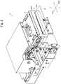
- Fig. 2 is a perspective view showing a card reader 1 structuring a card processing system 10 shown in Fig. 1 .
- Fig. 3 is a plan view showing a card 2 in Fig. 2 .
- a card processing system 10 in this embodiment is a system on which a card reader 1 structured to perform at least one of reading of data recorded in a card 2 and recording of data to a card 2 is mounted.
- the card processing system 10 is an ATM (Automated Teller Machine) which is installed and used in a bank or the like.
- the card processing system 10 includes a host control section 11 structured to control the card processing system 10 in addition to the card reader 1.
- a card reader 1 includes a control section 3 structured to control the card reader 1.
- the control section 3 is connected with the host control section 11.
- the card reader 1 includes a card insertion part 5 which is formed with an insertion port 4 into which a card 2 is inserted.
- a card conveying passage where a card 2 is conveyed is formed in an inside of the card reader 1 so as to be connected with the insertion port 4.
- the card reader 1 includes a card conveying mechanism structured to convey a card 2, a magnetic head configured to abut with a card 2 and perform reading of magnetic data recorded in the card 2 and/or recording magnetic data to the card 2, a head moving mechanism structured to move the magnetic head in a direction perpendicular to a conveying direction of the card 2, an IC contact block configured to contact with a terminal part 2b described below which is formed on the card 2 and perform data communication, and a contact block moving mechanism structured to move the IC contact block.
- a card conveying mechanism structured to convey a card 2
- a magnetic head configured to abut with a card 2 and perform reading of magnetic data recorded in the card 2 and/or recording magnetic data to the card 2
- a head moving mechanism structured to move the magnetic head in a direction perpendicular to a conveying direction of the card 2
- an IC contact block configured to contact with a terminal part 2b described below which is formed on the card 2 and perform data communication
- a contact block moving mechanism structured to move the IC
- a card 2 is a card made of vinyl chloride whose thickness is about 0.7-0.8mm.
- a card 2 in this embodiment is a card with a magnetic stripe in conformity with the international standard (for example, ISO/IEC7811) or JIS standard (for example, JISX6302) and is formed in a substantially rectangular shape whose four corners are rounded.
- a rear face of a card 2 is formed with a magnetic stripe 2a where magnetic data are recorded.
- the card 2 is a contact type IC card.
- an IC chip (not shown) is incorporated into the card 2
- a front face of the card 2 is formed with a terminal part 2b comprised of eight external connection terminals.
- no magnetic stripe 2a may be formed on a card 2.
- no IC chip (not shown) may be incorporated into a card 2.
- no terminal part 2b may be formed on a card 2.
- a magnetic stripe 2a is formed in a long and thin strip shape which is parallel to a longitudinal direction ("U"-direction in Fig. 3 ) of a card 2 formed in a substantially rectangular shape.
- the magnetic stripe 2a is formed over the entire region in the longitudinal direction of a card 2.
- the magnetic stripe 2a is formed on one end 2d side in the short-side direction of the card 2.
- the magnetic stripe 2a is formed within a predetermined range in the short-side direction of the card 2 with the one end 2d of the card 2 as a reference based on the international standard or JIS standard.
- the terminal part 2b is formed on one end side in the longitudinal direction of a card 2 and at substantially a middle position in the short-side direction of the card 2.
- Eight external connection terminals which structure the terminal part 2b are arranged in four lines in the short-side direction of a card 2 and two rows in the longitudinal direction of the card 2.
- a card 2 is conveyed in the "X” direction shown in Fig. 2 .
- a card 2 is inserted in the "X1” direction and taken into an inside, and the card 2 is ejected in the "X2" direction.
- the "X" direction is a conveying direction of a card 2
- the "X1” direction is an inserting direction of the card 2
- the "X2" direction is an ejecting direction of the card 2.
- a card 2 is taken into the card reader 1 so that the short-side direction of a card 2 and the "X" direction are coincided with each other.
- the card 2 is conveyed in an inside of the card reader 1 so that the short-side direction of the card 2 and the "X" direction are coincided with each other.
- the card reader 1 performs reading and/or recording of data for a card 2 inserted so that the short-side direction of the card 2 is an inserting direction of the card 2.
- the "Y” direction perpendicular to the "X” direction is a width direction of a card conveying passage and is a longitudinal direction of a card 2 taken into an inside of the card reader 1 in a correct posture.
- the "Z” direction perpendicular to the "X” direction and the “Y” direction is a height direction of the card conveying passage and is a thickness direction of a card 2 taken into the inside of the card reader 1.
- the card reader 1 is disposed so that the "Z" direction and a vertical direction are coincided with each other.
- the "X” direction is referred to as a "front and rear direction”
- the "Y” direction is referred to as a "right and left direction”
- the "Z" direction is an "upper and lower direction”.
- a magnetic head is disposed to a lower side of the card conveying passage and is abutted with a magnetic stripe 2a from a lower side of a card 2.
- an IC contact block is disposed to an upper side of the card conveying passage and is structured to contact with a terminal part 2b from an upper side of a card 2.
- a card insertion part 5 structures a front face side portion of the card reader 1.
- the card insertion part 5 includes a light emitting part 15 that is capable of being lighted or emitting light in a plurality of colors.
- the card insertion part 5 includes a thickness detection mechanism 16 structured to detect a thickness of a card 2 inserted into the insertion port 4, a width detection mechanism 17 structured to detect a width in the right and left direction of the card 2, a magnetic head (pre-head) 18 configured to detect a magnetic stripe 2a formed on the card 2, and a metal detection mechanism 19 structured to detect external connection terminals of an IC chip fixed on the card 2 (in other words, the terminal part 2b fixed on the card 2) (see Fig. 1 ).
- the light emitting part 15 is, as shown in Fig. 2 , disposed on both sides in the upper and lower direction of the insertion port 4. Further, the light emitting part 15 structures a part of a front face of the card reader 1. In other words, the light emitting part 15 is disposed in the vicinity of the insertion port 4.
- the light emitting part 15 includes a case body 21 formed of light transmitting material, a light source 22 (see Fig. 1 ) accommodated in an inside of the case body 21, and a light guide plate (not shown) which is accommodated in the inside of the case body 21 for diffusing light of the light source 22.
- the light emitting part 15 is capable of emitting light in various light emissions such as in multi-colors and multi-gradations and lighting or blinking depending on a light emission program described below.
- the light source 22 is an LED light source and is mounted on a circuit board not shown. This light source 22 is connected with the control section 3.
- the control section 3 performs a light emission control for controlling an emitting method of the light source 22 such as lighting or blinking and controlling an emission color of the light source 22.
- a plurality of pairs of three colors of LED light sources i.e., a red LED light source, a green LED light source and a blue LED light source is disposed in the light emitting part 15 as the light source 22.
- the control section 3 varies a color tone by changing a combination of lighting of the three colors of the LED light sources.
- the light source 22 is disposed on a right end side and/or a left end side of the inside of the case body 21 and the light guide plate is disposed over substantially an entire region in the right and left direction of the inside of the case body 21. Therefore, when the light source 22 emits light, the entire light emitting part 15 in the right and left direction is illuminated.
- a plurality of the light sources 22 may be disposed with a predetermined interval over substantially the entire region of the case body 21 in the right and left direction. In this case, no light guide plate may be provided.
- the light source 22 may be a light source other than an LED light source.
- the thickness detection mechanism 16 includes, for example, a movable member which is movable between a closing position where the movable member is disposed in the card conveying passage to close the card conveying passage and an open position where the movable member is retreated to a lower side of the card conveying passage when a card 2 passing the card conveying passage is contacted to open the card conveying passage, an urging member which urges the movable member toward the closing position, and a sensor configured to detect movement of the movable member.
- a movable member which is movable between a closing position where the movable member is disposed in the card conveying passage to close the card conveying passage and an open position where the movable member is retreated to a lower side of the card conveying passage when a card 2 passing the card conveying passage is contacted to open the card conveying passage
- an urging member which urges the movable member toward the closing position
- a sensor configured to detect movement of the movable member.
- the width detection mechanism 17 includes, for example, two detection levers which are disposed on both right and left end sides of the card insertion part 5 and capable of protruding to and retreating from the card conveying passage, and two sensors configured to detect respective movements of two detection levers.
- a part of the detection lever is disposed in an inside of the card conveying passage.
- each of both right and left ends of the card 2 is contacted with each of the two detection levers and the detection levers are turned and thus turning of each of the detection levers is detected by the sensor.
- the thickness detection mechanism 16 and the width detection mechanism 17 structure a card insertion detection mechanism for detecting a normal card 2 having been inserted into the insertion port 4 in a correct posture.
- An output signal of the magnetic head 18 is varied when a card 2 formed with a magnetic stripe 2a is inserted into the insertion port 4 and the card 2 is conveyed so that the magnetic stripe 2a is contacted with the magnetic head 18. Therefore, based on a detected result of the magnetic head 18, it can be detected whether a magnetic stripe 2a is formed on a card 2 or not.
- the metal detection mechanism 19 is a magnetic type sensor which includes an excitation coil, a detection coil and a core around which the excitation coil and the detection coil are wound.
- the metal detection mechanism 19 is disposed at a position in the right and left direction where a terminal part 2b of a card 2 inserted in a correct posture is passed.
- An output signal of the metal detection mechanism 19 is varied when a card 2 formed with a terminal part 2b is inserted into the insertion port 4. Therefore, based on a detected result of the metal detection mechanism 19, it can be detected whether a terminal part 2b is formed on a card 2 or not.
- Fig. 4 is an explanatory flow chart showing one example of light emission control of the light emitting part 15 shown in Fig. 1 .
- a host control section 11 is stored with a host side light emission program which specifies a combination of an emission color and an emitting method of the light emitting part 15 and is configured to perform light emission control of the light emitting part 15 by the control section 3.
- non-appropriate insertion of a card 2 When a case that a non-normal card 2 is inserted into the insertion port 4 and a case that a normal card 2 is inserted into the insertion port 4 in a wrong posture are referred to as a "non-appropriate insertion of a card 2" and, when a host side light emission program for performing light emission control of the light emitting part 15 at the time when a non-appropriate insertion of a card 2 has been detected based on detected results of the thickness detection mechanism 16 and the width detection mechanism 17 is referred to as a "host side abnormality light emission program", in this embodiment, the host side abnormality light emission program is stored in the host control section 11.
- a host side light emission program for performing light emission control of the light emitting part 15 at the time when a non-appropriate insertion of a card 2 is not detected is referred to as a "host side normal light emission program"
- the host side normal light emission program is stored in the host control section 11.
- a program for performing light emission control of the light emitting part 15 is not set in the control section 3 in an initial state.
- the host control section 11 sets an abnormality light emission program based on the host side abnormality light emission program in the control section 3 through a setting command at a predetermined timing before processing of a card 2 is started (step “S1"). In other words, the host control section 11 sets an abnormality light emission program in the control section 3 in advance.
- the control section 3 judges whether a normal card 2 has been inserted into the insertion port 4 in a correct posture or not based on detected results of the thickness detection mechanism 16 and the width detection mechanism 17 (step “S3"). In other words, the control section 3 judges whether a non-appropriate insertion of a card 2 has been detected or not based on detected results of the thickness detection mechanism 16 and the width detection mechanism 17.
- the host control section 11 sets a normal light emission program based on the host side normal light emission program in the control section 3 through a setting command at a predetermined timing before the step "S1" (step "S0").
- the control section 3 performs light emission control of the light emitting part 15 based on the normal light emission program. For example, in a standby state, the control section 3 sets the light emitting part 15 to be lighted continuously in blue color.
- control section 3 stores the normal light emission program (step "S4"). In other words, in a case that a non-appropriate insertion of a card 2 has been detected in the step "S3", the control section 3 stores the normal light emission program just before a non-appropriate insertion of a card 2 is detected based on detected results of the thickness detection mechanism 16 and the width detection mechanism 17.
- the control section 3 performs light emission control of the light emitting part 15 based on the abnormality light emission program previously set in the step "S1" (step "S5").
- the control section 3 stores the normal light emission program and, after that, the control section 3 performs light emission control of the light emitting part 15 based on the previously set abnormality light emission program. For example, the control section 3 intermittently blinks the light emitting part 15 in a red color.
- step "S6" After that, a non-normal card 2 or a normal card 2 inserted in a wrong posture is taken out from the insertion port 4 and the non-appropriate insertion of the card 2 is not detected (when "Yes” in step "S6"), the control section 3 reads out the normal light emission program stored in the step "S4" just before the non-appropriate insertion of the card 2 is detected, and the control section 3 performs light emission control of the light emitting part 15 based on the read-out normal light emission program (step "S7").
- the control section 3 makes light emission control of the light emitting part 15 be returned from light emission control based on the abnormality light emission program to light emission control based on the normal light emission program stored in the step "S4" just before the non-appropriate insertion of the card 2 is detected.
- the flow is returned to the step "S2".
- step "S3" when a normal card 2 has been inserted into the insertion port 4 in a correct posture, the control section 3 judges whether or not existence/absence of a magnetic stripe 2a and existence/absence of an IC contact point of the inserted card 2 are coincided with a condition of a card 2 to be processed in the card reader 1 based on detected results of the magnetic head 18 and the metal detection mechanism 19 (step "S8").
- the control section 3 judges whether an inserted card 2 is provided with a magnetic stripe 2a and an IC contact point or not based on detected results of the magnetic head 18 and the metal detection mechanism 19.
- step "S8" when existence/absence of a magnetic stripe 2a and existence/absence of an IC contact point of the inserted card 2 are coincided with a condition of a card 2 to be processed in the card reader 1, the control section 3 continues processing of the card 2 in the card reader 1 (step “S9”). Specifically, in the step “S9", the card 2 is conveyed to an inside of the card reader 1 and reading and/or recording of data by a magnetic head and the IC contact block and the like are performed. In this embodiment, in the step “S9", the control section 3 performs light emission control of the light emitting part 15 based on the normal light emission program.
- step "S8" when existence/absence of a magnetic stripe 2a and existence/absence of an IC contact point of an inserted card 2 are not coincided with a condition of a card 2 to be processed in the card reader 1, the flow is advanced to the step "S6" and the control section 3 judges whether a non-normal card 2 or a normal card 2 inserted in a wrong posture has been taken out from the insertion port 4 or not based on detected results of the thickness detection mechanism 16 and the width detection mechanism 17.
- the host control section 11 sets an abnormality light emission program based on a host side abnormality light emission program stored in the host control section 11 and a normal light emission program based on a host side normal light emission program stored in the host control section 11 in the control section 3 in advance, and the control section 3 performs light emission control of the light emitting part 15 based on the abnormality light emission program and the normal light emission program which are set in advance. Therefore, according to this embodiment, even when the firmware stored in the control section 3 is common, the control section 3 is capable of making the light emitting part 15 be lighted in various emission colors and emitting methods based on the abnormality light emission program and the normal light emission program previously set by the host control section 11. In other words, in this embodiment, even when the firmware stored in the control section 3 is common, the light emitting part 15 is capable of being lighted in various emission colors and emitting methods according to needs of customers such as a bank in which the card processing system 10 is installed.
- the abnormality light emission program is previously set in the control section 3 and, when a non-appropriate insertion of a card 2 is detected based on detected results of the thickness detection mechanism 16 and the width detection mechanism 17, light emission control of the light emitting part 15 is performed by the control section 3 based on the abnormality light emission program. Therefore, according to this embodiment, light emission control based on the abnormality light emission program can be started immediately.
- the control section 3 performs light emission control of the light emitting part 15 based on the abnormality light emission program and thus light emission control based on the abnormality light emission program can be started immediately. Therefore, according to this embodiment, light emission control of the light emitting part 15 can be performed synchronously with a card operation of a user who inserts a card 2 into the card reader 1.
- the control section 3 when a non-appropriate insertion of a card 2 is detected based on detected results of the thickness detection mechanism 16 and the width detection mechanism 17, the control section 3 stores a normal light emission program and, after that, the control section 3 performs light emission control of the light emitting part 15 based on a previously set abnormality light emission program and, when the non-normal card 2 or the normal card 2 inserted in a wrong posture has been taken out from the insertion port 4, the control section 3 reads out the normal light emission program stored just before the non-appropriate insertion of the card 2 is detected and performs light emission control of the light emitting part 15 based on the read-out normal light emission program.
- light emission control of the light emitting part 15 based on the normal light emission program is capable of being started immediately. Accordingly, light emission control of the light emitting part 15 is capable of being performed synchronously with a card operation of a user who inserts a card 2 into the card reader 1.
- the light emitting part 15 is not required to be lighted and, alternatively, the light emitting part 15 may be continuously lighted in a green color in a standby state before an insertion of a card 2 is detected by the thickness detection mechanism 16 and/or the width detection mechanism 17.
- the control section 3 stores a state of light emission control (normal light emission program) of the light emitting part 15 just before the non-appropriate insertion of the card 2 is detected and, after that, the control section 3 performs light emission control of the light emitting part 15 based on the previously set abnormality light emission program.
- the firmware can be used in common and light emission control of the light emitting part 15 of the card reader 1 coped with a need of a customer can be attained.
- a host side abnormality light emission program is stored in the host control section 11 and, in the step "S1", the host control section 11 sets an abnormality light emission program based on the host side abnormality light emission program in the control section 3.
- the present invention is not limited to this embodiment.
- a host side light emission program for performing light emission control of the light emitting part 15 in a predetermined situation except when a non-appropriate insertion of a card 2 has been detected is stored in the host control section 11 and, in the step "S1", the host control section 11 may set a light emission program based on the host side light emission program in the control section 3.
- a host side light emission program for performing light emission control of the light emitting part 15 when another card 2 is inserted into the insertion port 4 in a state that a card 2 has been taken into an inside of the card reader 1 and a predetermined processing is being performed is stored in the host control section 11 and, in the step "S1", the host control section 11 may set a light emission program based on the host side light emission program in the control section 3.
- the control section 3 performs light emission control of the light emitting part 15 based on the previously set light emission program.
- the host control section 11 sets a normal light emission program based on a host side normal light emission program in the control section 3 at a predetermined timing before the step "S1" through a setting command.
- a normal light emission program may be set in the firmware stored in the control section 3 in advance.
- the magnetic head 18 in a case that the magnetic head 18 is disposed only to an under face side of a card conveying passage, it can be detected whether a card 2 has been inserted into the insertion port 4 in a state that its rear face faces a lower side, or a card 2 has been inserted into the insertion port 4 in a state that its front face faces a lower side. Further, in a case that the metal detection mechanism 19 is disposed on the left end side of the card conveying passage in Fig. 2 , when a card 2 is inserted from one end 2d side in a short-side direction of the card 2 in a state that its rear face faces a lower side, the terminal part 2b of the card 2 is detected by the metal detection mechanism 19.
- the terminal part 2b of the card 2 is detected by the metal detection mechanism 19. Therefore, based on a detected result of the magnetic head 18 and a detected result of the metal detection mechanism 19, it can be detected whether a card 2 has been inserted from one end 2d side of the card 2, or the card 2 has been inserted from the other end 2e side of the card 2.
- a card 2 may be detected whether a card 2 has been inserted into the insertion port 4 in a correct posture or not by detecting whether a card 2 has been inserted into the insertion port 4 so that a short-side direction of the card 2 is coincided with the front and rear direction by using the width detection mechanism 17 and, in addition, by detecting whether a card 2 has been inserted into the insertion port 4 in a state that its rear face faces a lower side or not, and by detecting whether the card 2 has been inserted from one end 2d side or not by using the magnetic head 18 and the metal detection mechanism 19.
- a card insertion detection mechanism for detecting that a normal card 2 has been inserted into the insertion port 4 in a correct posture is structured of the thickness detection mechanism 16, the width detection mechanism 17, the magnetic head 18 and the metal detection mechanism 19. Further, in this case, in the step "S3" in the flow chart shown in Fig. 4 , when a normal card 2 is inserted into the insertion port 4 in a correct posture, the flow is advanced to the step "S9".
- the card 2 is a rectangular card made of vinyl chloride whose thickness is about 0.7-0.8mm.
- the card 2 may be a PET (polyethylene terephthalate) card whose thickness is about 0.18-0.36mm or may be a paper card having a predetermined thickness.
- the card reader 1 performs reading and/or recording of data to a card 2 inserted so that a short-side direction of a card 2 is an inserting direction of the card 2.
- the card reader 1 may perform reading and/or recording of data to a card 2 inserted so that a longitudinal direction of a card 2 is an inserting direction of the card 2.
Landscapes
- Engineering & Computer Science (AREA)
- Artificial Intelligence (AREA)
- Computer Vision & Pattern Recognition (AREA)
- Physics & Mathematics (AREA)
- General Physics & Mathematics (AREA)
- Theoretical Computer Science (AREA)
- Conveying Record Carriers (AREA)
- Credit Cards Or The Like (AREA)
- Control Of Vending Devices And Auxiliary Devices For Vending Devices (AREA)
Abstract
Description
- The present invention relates to a card processing system on which a card reader is mounted.
- Conventionally, a card reader has been known in which a card inserted into a gate port is taken into its inside by a card conveying mechanism to perform a predetermined processing (see, for example, Patent Literature 1). In the card reader described in
Patent Literature 1, a card insertion guide body for guiding a card to an inside of the card reader is attached to the gate port. A card insertion guide body includes a case formed of light transmitting material and a light source accommodated in the case. In the card reader, since the gate port into which a card is to be inserted is illuminated, visibility of the gate port can be enhanced. - Conventionally, as a card reader whose gate port is illuminated like the card reader described in
Patent Literature 1, a card reader has been utilized which includes a detection mechanism structured to detect that a normal card has been inserted into the gate port in a correct posture. In the card reader, when a non-normal card is inserted or, when a normal card is inserted in a wrong posture, the light source is illuminated in a different emission color and a different emitting method from an emission color and an emitting method when a normal card has been inserted in a correct posture. For example, when a normal card has been inserted in a correct posture, the light source is lighted in blue and, when a non-normal card has been inserted or, when a normal card has been inserted in a wrong posture, the light source is blinked in red. As described above, in the card reader, when a non-normal card has been inserted or, when a normal card has been inserted in a wrong posture, an emission color and an emitting method of a light source are changed to guide a user to insert a normal card in a correct posture. - In this type of a card reader, an emission color and an emitting method of a light source are commonly controlled on the basis of a predetermined program in a firmware stored in a control section of the card reader.
- [Patent literature 1] Japanese Patent Laid-Open No.
2004-185513 - In recent years, a light source which is capable of emitting a light in a multi-color and multi-gradation may be used in a card reader whose gate port is illuminated like the card reader described in
Patent Literature 1. However, in the conventional card reader, an emission color and an emitting method of a light source are controlled on the basis of a program in a firmware stored in a control section of the card reader. Therefore, even when a light source capable of emitting a light in a multi-color and multi-gradation is used in a card reader, an emission color and an emitting method of a light source are fixed for each of the card readers. In other words, in the conventional card reader, it is difficult that a light source is lighted in various emission colors and emitting methods according to needs of respective customers such as a bank where the card reader is installed. - On the other hand, if a program in a firmware is prepared for each of customers so that a light source is lighted in an emission color and an emitting method according to a need of a customer, the light source can be lighted in various emission colors and emitting methods so as to meet the needs for respective customers. However, in this case, a firmware is required to be prepared for each of customers and thus a design of the firmware becomes complicated and manufacture management and inventory management of card readers also become complicated.
- In view of the problem described above, the present invention provides a card processing system in which a light emitting part of a card reader is capable of being lighted in various emission colors and emitting methods according to a need of a customer even when the firmware stored in a control section of the card reader is common.
- To solve the above mentioned problem, the present invention provides a card processing system on which a card reader structured to perform at least one of reading of data recorded in a card and recording of data to the card is mounted, and the card processing system includes a host control section for controlling the card processing system. The card reader includes a card insertion part which is formed with an insertion port into which the card is inserted and a control section for controlling the card reader, and the card insertion part includes a light emitting part which is capable of emitting light in plurality of colors. The control section is connected with the host control section and performs light emission control which controls an emission color and an emitting method of the light emitting part. The host control section is stored with a host side light emission program which specifies a combination of an emission color and an emitting method of the light emitting part and is configured to perform light emission control, and the host control section previously sets a light emission program based on the host side light emission program in the control section, and the control section performs the light emission control based on the previously set light emission program.
- In the card processing system in accordance with the present invention, the host control section previously sets a light emission program in the control section of the card reader based on the host side light emission program stored in the host control section, and the control section performs the light emission control based on the previously set light emission program. Therefore, according to the present invention, even when the firmware stored in the control section of the card reader is common, the control section is capable of making the light emitting part of the card reader be lighted in various emission colors and emitting methods based on the light emission program previously set by the host control section. In other words, in the present invention, even when the firmware stored in the control section of the card reader is common, the light emitting part is capable of being lighted in various emission colors and emitting methods according to needs of customers such as a bank in which the card processing system is installed.
- For example, even if the firmware stored in the control section of the card reader is common, the light emitting part of the card reader is lighted in various emission colors and emitting methods each time by communicating between the host control section and the control section, and thus the light emitting part is capable of being lighted in various emission colors and emitting methods according to needs of customers. However, in this case, a time before the light emitting part is lighted becomes longer. In other words, in this case, responsibility of the light emitting part is lowered. However, according to the present invention, the control section performs light emission control based on the light emission program previously set in the control section and thus responsibility of the light emitting part is capable of being enhanced.
- In the present invention, for example, the card insertion part includes a card insertion detection mechanism structured to detect that a normal card is inserted into the insertion port in a correct posture. When an insertion of a non-normal card into the insertion port and an insertion of the normal card into the insertion port in a wrong posture is referred to as a non-appropriate insertion of the card, when the host side light emission program configured to perform the light emission control in a case that the non-appropriate insertion of the card has been detected based on a detected result by the card insertion detection mechanism is referred to as a host side abnormality light emission program and, when the light emission program which is previously set in the control section based on the host side abnormality light emission program is referred to as an abnormality light emission program, the host control section is stored with the host side abnormality light emission program, the host control section previously sets the abnormality light emission program based on the host side abnormality light emission program in the control section and, when the non-appropriate insertion of the card has been detected based on the detected result of the card insertion detection mechanism, the control section performs the light emission control based on the previously set abnormality light emission program.
- In this case, even when the firmware stored in the control section of the card reader is common, the light emitting part is capable of being lighted in various emission colors and emitting methods according to needs of customers when a non-appropriate insertion of the card is detected. Further, in a case that the abnormality light emission program is not previously set in the control section and the host control section performs light emission control of the light emitting part when a non-appropriate insertion of a card is detected, a delay time becomes long and light emission control of the light emitting part based on the abnormality light emission program cannot be started immediately. However, in the present invention, the abnormality light emission program is previously set in the control section and, when a non-appropriate insertion of a card has been detected based on a detected result of the card insertion detection mechanism, the control section performs light emission control based on the abnormality light emission program and thus light emission control based on the abnormality light emission program can be started immediately. Therefore, light emission control can be performed synchronously with a card operation of a user who inserts a card into the card reader.
- In the present invention, it is preferable that, when the light emission program configured to perform the light emission control just before that the non-appropriate insertion of the card is detected based on the detected result of the card insertion detection mechanism is referred to as a normal light emission program, the control section stores the normal light emission program when the non-appropriate insertion of the card has been detected based on the detected result of the card insertion detection mechanism, and after that, the control section performs the light emission control based on the previously set abnormality light emission program and, when the non-normal card or the normal card inserted in a wrong posture is taken out and the non-appropriate insertion of the card is not detected, the control section reads out the normal light emission program having been stored and performs the light emission control based on the normal light emission program. According to this structure, after the non-normal card or the normal card inserted in a wrong posture is taken out, light emission control based on the normal light emission program is capable of being started immediately. Therefore, light emission control can be performed synchronously with a card operation of a user who inserts a card into the card reader.
- In the present invention, the card insertion detection mechanism includes, for example, a thickness detection mechanism structured to detect a thickness of the card and a width detection mechanism structured to detect a width of the card in a direction perpendicular to an inserting direction of the card.
- In the present invention, for example, the card is formed in a substantially rectangular shape, and the card reader performs at least one of reading of data and recording of data to the card which is inserted so that a short-side direction of the card is an inserting direction of the card. In this case, a card can be inserted into the insertion port so that a longitudinal direction of the card is an inserting direction of the card and thus a possibility that a card is inserted into the insertion port in a wrong posture becomes higher. However, even if a card is inserted into the insertion port in a wrong posture, an insertion of the card in a wrong posture can be notified to a user of the card reader by making the light emitting part being lighted.
- As described above, in the card processing system of the present invention, even when the firmware stored in the control section of the card reader is common, the light emitting part is capable of being lighted in various emission colors and emitting methods according to needs of customers.
-
- [
Fig. 1 ]
Fig. 1 is an explanatory block diagram showing a schematic structure of a card processing system in accordance with an embodiment of the present invention. - [
Fig. 2 ]
Fig. 2 is a perspective view showing a card reader structuring a card processing system shown inFig. 1 . - [
Fig. 3 ]
Fig. 3 is a plan view showing a card inFig. 2 . - [
Fig. 4 ]
Fig. 4 is an explanatory flow chart showing one example of light emission control of a light emitting part shown inFig. 1 . - An embodiment of the present invention will be described below with reference to the accompanying drawings.
-
Fig. 1 is an explanatory block diagram showing a schematic structure of acard processing system 10 in accordance with an embodiment of the present invention.Fig. 2 is a perspective view showing acard reader 1 structuring acard processing system 10 shown inFig. 1 .Fig. 3 is a plan view showing acard 2 inFig. 2 . - A
card processing system 10 in this embodiment is a system on which acard reader 1 structured to perform at least one of reading of data recorded in acard 2 and recording of data to acard 2 is mounted. For example, thecard processing system 10 is an ATM (Automated Teller Machine) which is installed and used in a bank or the like. Thecard processing system 10 includes ahost control section 11 structured to control thecard processing system 10 in addition to thecard reader 1. - A
card reader 1 includes acontrol section 3 structured to control thecard reader 1. Thecontrol section 3 is connected with thehost control section 11. Further, thecard reader 1 includes acard insertion part 5 which is formed with aninsertion port 4 into which acard 2 is inserted. A card conveying passage where acard 2 is conveyed is formed in an inside of thecard reader 1 so as to be connected with theinsertion port 4. In addition, thecard reader 1 includes a card conveying mechanism structured to convey acard 2, a magnetic head configured to abut with acard 2 and perform reading of magnetic data recorded in thecard 2 and/or recording magnetic data to thecard 2, a head moving mechanism structured to move the magnetic head in a direction perpendicular to a conveying direction of thecard 2, an IC contact block configured to contact with aterminal part 2b described below which is formed on thecard 2 and perform data communication, and a contact block moving mechanism structured to move the IC contact block. - A
card 2 is a card made of vinyl chloride whose thickness is about 0.7-0.8mm. Acard 2 in this embodiment is a card with a magnetic stripe in conformity with the international standard (for example, ISO/IEC7811) or JIS standard (for example, JISX6302) and is formed in a substantially rectangular shape whose four corners are rounded. A rear face of acard 2 is formed with amagnetic stripe 2a where magnetic data are recorded. Further, thecard 2 is a contact type IC card. In other words, an IC chip (not shown) is incorporated into thecard 2, and a front face of thecard 2 is formed with aterminal part 2b comprised of eight external connection terminals. In accordance with an embodiment of the present invention, nomagnetic stripe 2a may be formed on acard 2. Further, no IC chip (not shown) may be incorporated into acard 2. In other words, noterminal part 2b may be formed on acard 2. - A
magnetic stripe 2a is formed in a long and thin strip shape which is parallel to a longitudinal direction ("U"-direction inFig. 3 ) of acard 2 formed in a substantially rectangular shape. Themagnetic stripe 2a is formed over the entire region in the longitudinal direction of acard 2. Further, in a short-side direction ("V"-direction inFig. 3 ) of thecard 2, themagnetic stripe 2a is formed on oneend 2d side in the short-side direction of thecard 2. Specifically, themagnetic stripe 2a is formed within a predetermined range in the short-side direction of thecard 2 with the oneend 2d of thecard 2 as a reference based on the international standard or JIS standard. - The
terminal part 2b is formed on one end side in the longitudinal direction of acard 2 and at substantially a middle position in the short-side direction of thecard 2. Eight external connection terminals which structure theterminal part 2b are arranged in four lines in the short-side direction of acard 2 and two rows in the longitudinal direction of thecard 2. - In this embodiment, a
card 2 is conveyed in the "X" direction shown inFig. 2 . Specifically, acard 2 is inserted in the "X1" direction and taken into an inside, and thecard 2 is ejected in the "X2" direction. In other words, the "X" direction is a conveying direction of acard 2, the "X1" direction is an inserting direction of thecard 2 and the "X2" direction is an ejecting direction of thecard 2. Further, in this embodiment, acard 2 is taken into thecard reader 1 so that the short-side direction of acard 2 and the "X" direction are coincided with each other. Further, thecard 2 is conveyed in an inside of thecard reader 1 so that the short-side direction of thecard 2 and the "X" direction are coincided with each other. In other words, thecard reader 1 performs reading and/or recording of data for acard 2 inserted so that the short-side direction of thecard 2 is an inserting direction of thecard 2. - The "Y" direction perpendicular to the "X" direction is a width direction of a card conveying passage and is a longitudinal direction of a
card 2 taken into an inside of thecard reader 1 in a correct posture. Further, the "Z" direction perpendicular to the "X" direction and the "Y" direction is a height direction of the card conveying passage and is a thickness direction of acard 2 taken into the inside of thecard reader 1. In this embodiment, thecard reader 1 is disposed so that the "Z" direction and a vertical direction are coincided with each other. In the following descriptions, the "X" direction is referred to as a "front and rear direction", the "Y" direction is referred to as a "right and left direction", and the "Z" direction is an "upper and lower direction". In this embodiment, a magnetic head is disposed to a lower side of the card conveying passage and is abutted with amagnetic stripe 2a from a lower side of acard 2. Further, an IC contact block is disposed to an upper side of the card conveying passage and is structured to contact with aterminal part 2b from an upper side of acard 2. - A
card insertion part 5 structures a front face side portion of thecard reader 1. Thecard insertion part 5 includes alight emitting part 15 that is capable of being lighted or emitting light in a plurality of colors. Further, thecard insertion part 5 includes athickness detection mechanism 16 structured to detect a thickness of acard 2 inserted into theinsertion port 4, awidth detection mechanism 17 structured to detect a width in the right and left direction of thecard 2, a magnetic head (pre-head) 18 configured to detect amagnetic stripe 2a formed on thecard 2, and ametal detection mechanism 19 structured to detect external connection terminals of an IC chip fixed on the card 2 (in other words, theterminal part 2b fixed on the card 2) (seeFig. 1 ). - The
light emitting part 15 is, as shown inFig. 2 , disposed on both sides in the upper and lower direction of theinsertion port 4. Further, thelight emitting part 15 structures a part of a front face of thecard reader 1. In other words, thelight emitting part 15 is disposed in the vicinity of theinsertion port 4. Thelight emitting part 15 includes a case body 21 formed of light transmitting material, a light source 22 (seeFig. 1 ) accommodated in an inside of the case body 21, and a light guide plate (not shown) which is accommodated in the inside of the case body 21 for diffusing light of thelight source 22. In this embodiment, thelight emitting part 15 is capable of emitting light in various light emissions such as in multi-colors and multi-gradations and lighting or blinking depending on a light emission program described below. - The
light source 22 is an LED light source and is mounted on a circuit board not shown. Thislight source 22 is connected with thecontrol section 3. Thecontrol section 3 performs a light emission control for controlling an emitting method of thelight source 22 such as lighting or blinking and controlling an emission color of thelight source 22. Specifically, a plurality of pairs of three colors of LED light sources, i.e., a red LED light source, a green LED light source and a blue LED light source is disposed in thelight emitting part 15 as thelight source 22. Thecontrol section 3 varies a color tone by changing a combination of lighting of the three colors of the LED light sources. Further, in this embodiment, thelight source 22 is disposed on a right end side and/or a left end side of the inside of the case body 21 and the light guide plate is disposed over substantially an entire region in the right and left direction of the inside of the case body 21. Therefore, when thelight source 22 emits light, the entirelight emitting part 15 in the right and left direction is illuminated. In accordance with an embodiment of the present invention, a plurality of thelight sources 22 may be disposed with a predetermined interval over substantially the entire region of the case body 21 in the right and left direction. In this case, no light guide plate may be provided. Further, thelight source 22 may be a light source other than an LED light source. - The
thickness detection mechanism 16 includes, for example, a movable member which is movable between a closing position where the movable member is disposed in the card conveying passage to close the card conveying passage and an open position where the movable member is retreated to a lower side of the card conveying passage when acard 2 passing the card conveying passage is contacted to open the card conveying passage, an urging member which urges the movable member toward the closing position, and a sensor configured to detect movement of the movable member. In thethickness detection mechanism 16, when acard 2 having a normal thickness is inserted into theinsertion port 4, movement of the movable member is detected by the sensor. However, even when acard 2 having a thickness thinner than a normal thickness is inserted into theinsertion port 4, movement of the movable member is not detected by the sensor. Therefore, based on a detected result of the sensor, it is capable of detecting whether acard 2 having a normal thickness has been inserted into theinsertion port 4 or not. - The
width detection mechanism 17 includes, for example, two detection levers which are disposed on both right and left end sides of thecard insertion part 5 and capable of protruding to and retreating from the card conveying passage, and two sensors configured to detect respective movements of two detection levers. In a standby state before acard 2 is inserted into thecard reader 1, a part of the detection lever is disposed in an inside of the card conveying passage. In this state, when acard 2 is inserted into theinsertion port 4 so that a short-side direction of thecard 2 is coincided with the front and rear direction, each of both right and left ends of thecard 2 is contacted with each of the two detection levers and the detection levers are turned and thus turning of each of the detection levers is detected by the sensor. On the other hand, even when acard 2 is inserted into theinsertion port 4 so that a longitudinal direction of thecard 2 is coincided with the front and rear direction or, even when acard 2 whose width in its short-side direction is narrower than a normal width is inserted into theinsertion port 4, turning of at least one detection lever is not detected by the sensor. Therefore, based on detected results by the two sensors, it can be detected whether acard 2 whose width in its short-side direction is a normal width has been inserted into theinsertion port 4 so that its short-side direction and the front and rear direction are coincided with each other or not. In other words, based on detected results by the two sensors, it can be detected whether acard 2 whose width in its short-side direction is a normal width has been inserted into theinsertion port 4 in a correct posture or not. - In this embodiment, the
thickness detection mechanism 16 and thewidth detection mechanism 17 structure a card insertion detection mechanism for detecting anormal card 2 having been inserted into theinsertion port 4 in a correct posture. - An output signal of the
magnetic head 18 is varied when acard 2 formed with amagnetic stripe 2a is inserted into theinsertion port 4 and thecard 2 is conveyed so that themagnetic stripe 2a is contacted with themagnetic head 18. Therefore, based on a detected result of themagnetic head 18, it can be detected whether amagnetic stripe 2a is formed on acard 2 or not. - The
metal detection mechanism 19 is a magnetic type sensor which includes an excitation coil, a detection coil and a core around which the excitation coil and the detection coil are wound. Themetal detection mechanism 19 is disposed at a position in the right and left direction where aterminal part 2b of acard 2 inserted in a correct posture is passed. An output signal of themetal detection mechanism 19 is varied when acard 2 formed with aterminal part 2b is inserted into theinsertion port 4. Therefore, based on a detected result of themetal detection mechanism 19, it can be detected whether aterminal part 2b is formed on acard 2 or not. -
Fig. 4 is an explanatory flow chart showing one example of light emission control of thelight emitting part 15 shown inFig. 1 . - In the
card processing system 10, ahost control section 11 is stored with a host side light emission program which specifies a combination of an emission color and an emitting method of thelight emitting part 15 and is configured to perform light emission control of thelight emitting part 15 by thecontrol section 3. When a case that anon-normal card 2 is inserted into theinsertion port 4 and a case that anormal card 2 is inserted into theinsertion port 4 in a wrong posture are referred to as a "non-appropriate insertion of acard 2" and, when a host side light emission program for performing light emission control of thelight emitting part 15 at the time when a non-appropriate insertion of acard 2 has been detected based on detected results of thethickness detection mechanism 16 and thewidth detection mechanism 17 is referred to as a "host side abnormality light emission program", in this embodiment, the host side abnormality light emission program is stored in thehost control section 11. Further, when a host side light emission program for performing light emission control of thelight emitting part 15 at the time when a non-appropriate insertion of acard 2 is not detected is referred to as a "host side normal light emission program", the host side normal light emission program is stored in thehost control section 11. On the other hand, a program for performing light emission control of thelight emitting part 15 is not set in thecontrol section 3 in an initial state. - The
host control section 11 sets an abnormality light emission program based on the host side abnormality light emission program in thecontrol section 3 through a setting command at a predetermined timing before processing of acard 2 is started (step "S1"). In other words, thehost control section 11 sets an abnormality light emission program in thecontrol section 3 in advance. In this state, when an insertion of acard 2 is detected by thethickness detection mechanism 16 and/or the width detection mechanism 17 ("Yes" in step "S2"), thecontrol section 3 judges whether anormal card 2 has been inserted into theinsertion port 4 in a correct posture or not based on detected results of thethickness detection mechanism 16 and the width detection mechanism 17 (step "S3"). In other words, thecontrol section 3 judges whether a non-appropriate insertion of acard 2 has been detected or not based on detected results of thethickness detection mechanism 16 and thewidth detection mechanism 17. - In this embodiment, the
host control section 11 sets a normal light emission program based on the host side normal light emission program in thecontrol section 3 through a setting command at a predetermined timing before the step "S1" (step "S0"). In a standby state before an insertion of acard 2 is detected by thethickness detection mechanism 16 and thewidth detection mechanism 17, thecontrol section 3 performs light emission control of thelight emitting part 15 based on the normal light emission program. For example, in a standby state, thecontrol section 3 sets thelight emitting part 15 to be lighted continuously in blue color. - In a case that a non-appropriate insertion of a
card 2 has been detected in the step "S3", thecontrol section 3 stores the normal light emission program (step "S4"). In other words, in a case that a non-appropriate insertion of acard 2 has been detected in the step "S3", thecontrol section 3 stores the normal light emission program just before a non-appropriate insertion of acard 2 is detected based on detected results of thethickness detection mechanism 16 and thewidth detection mechanism 17. - After that, the
control section 3 performs light emission control of thelight emitting part 15 based on the abnormality light emission program previously set in the step "S1" (step "S5"). In other words, when a non-appropriate insertion of acard 2 is detected based on detected results of thethickness detection mechanism 16 and thewidth detection mechanism 17, thecontrol section 3 stores the normal light emission program and, after that, thecontrol section 3 performs light emission control of thelight emitting part 15 based on the previously set abnormality light emission program. For example, thecontrol section 3 intermittently blinks thelight emitting part 15 in a red color. - After that, a
non-normal card 2 or anormal card 2 inserted in a wrong posture is taken out from theinsertion port 4 and the non-appropriate insertion of thecard 2 is not detected (when "Yes" in step "S6"), thecontrol section 3 reads out the normal light emission program stored in the step "S4" just before the non-appropriate insertion of thecard 2 is detected, and thecontrol section 3 performs light emission control of thelight emitting part 15 based on the read-out normal light emission program (step "S7"). In other words, when it is detected that anon-normal card 2 or anormal card 2 inserted in a wrong posture has been taken out from theinsertion port 4 based on detected results of thethickness detection mechanism 16 and thewidth detection mechanism 17, thecontrol section 3 makes light emission control of thelight emitting part 15 be returned from light emission control based on the abnormality light emission program to light emission control based on the normal light emission program stored in the step "S4" just before the non-appropriate insertion of thecard 2 is detected. When the light emission control of thelight emitting part 15 is returned to light emission control based on the normal light emission program, the flow is returned to the step "S2". - On the other hand, in the step "S3", when a
normal card 2 has been inserted into theinsertion port 4 in a correct posture, thecontrol section 3 judges whether or not existence/absence of amagnetic stripe 2a and existence/absence of an IC contact point of the insertedcard 2 are coincided with a condition of acard 2 to be processed in thecard reader 1 based on detected results of themagnetic head 18 and the metal detection mechanism 19 (step "S8"). For example, in a case that acard 2 to be processed in thecard reader 1 is acard 2 having amagnetic stripe 2a and an IC contact point, in the step "S8", thecontrol section 3 judges whether an insertedcard 2 is provided with amagnetic stripe 2a and an IC contact point or not based on detected results of themagnetic head 18 and themetal detection mechanism 19. - In the step "S8", when existence/absence of a
magnetic stripe 2a and existence/absence of an IC contact point of the insertedcard 2 are coincided with a condition of acard 2 to be processed in thecard reader 1, thecontrol section 3 continues processing of thecard 2 in the card reader 1 (step "S9"). Specifically, in the step "S9", thecard 2 is conveyed to an inside of thecard reader 1 and reading and/or recording of data by a magnetic head and the IC contact block and the like are performed. In this embodiment, in the step "S9", thecontrol section 3 performs light emission control of thelight emitting part 15 based on the normal light emission program. - On the other hand, in the step "S8", when existence/absence of a
magnetic stripe 2a and existence/absence of an IC contact point of an insertedcard 2 are not coincided with a condition of acard 2 to be processed in thecard reader 1, the flow is advanced to the step "S6" and thecontrol section 3 judges whether anon-normal card 2 or anormal card 2 inserted in a wrong posture has been taken out from theinsertion port 4 or not based on detected results of thethickness detection mechanism 16 and thewidth detection mechanism 17. - As described above, in this embodiment, the
host control section 11 sets an abnormality light emission program based on a host side abnormality light emission program stored in thehost control section 11 and a normal light emission program based on a host side normal light emission program stored in thehost control section 11 in thecontrol section 3 in advance, and thecontrol section 3 performs light emission control of thelight emitting part 15 based on the abnormality light emission program and the normal light emission program which are set in advance. Therefore, according to this embodiment, even when the firmware stored in thecontrol section 3 is common, thecontrol section 3 is capable of making thelight emitting part 15 be lighted in various emission colors and emitting methods based on the abnormality light emission program and the normal light emission program previously set by thehost control section 11. In other words, in this embodiment, even when the firmware stored in thecontrol section 3 is common, thelight emitting part 15 is capable of being lighted in various emission colors and emitting methods according to needs of customers such as a bank in which thecard processing system 10 is installed. - In this embodiment, the abnormality light emission program is previously set in the
control section 3 and, when a non-appropriate insertion of acard 2 is detected based on detected results of thethickness detection mechanism 16 and thewidth detection mechanism 17, light emission control of thelight emitting part 15 is performed by thecontrol section 3 based on the abnormality light emission program. Therefore, according to this embodiment, light emission control based on the abnormality light emission program can be started immediately. In other words, in a case that the abnormality light emission program is not previously set in thecontrol section 3 and thehost control section 11 performs light emission control of thelight emitting part 15 when a non-appropriate insertion of acard 2 is detected, a delay time becomes long and light emission control of thelight emitting part 15 based on the abnormality light emission program cannot be started immediately. However, in this embodiment, thecontrol section 3 performs light emission control of thelight emitting part 15 based on the abnormality light emission program and thus light emission control based on the abnormality light emission program can be started immediately. Therefore, according to this embodiment, light emission control of thelight emitting part 15 can be performed synchronously with a card operation of a user who inserts acard 2 into thecard reader 1. - In this embodiment, when a non-appropriate insertion of a
card 2 is detected based on detected results of thethickness detection mechanism 16 and thewidth detection mechanism 17, thecontrol section 3 stores a normal light emission program and, after that, thecontrol section 3 performs light emission control of thelight emitting part 15 based on a previously set abnormality light emission program and, when thenon-normal card 2 or thenormal card 2 inserted in a wrong posture has been taken out from theinsertion port 4, thecontrol section 3 reads out the normal light emission program stored just before the non-appropriate insertion of thecard 2 is detected and performs light emission control of thelight emitting part 15 based on the read-out normal light emission program. Therefore, according to this embodiment, after anon-normal card 2 or anormal card 2 inserted in a wrong posture is taken out from theinsertion port 4, light emission control of thelight emitting part 15 based on the normal light emission program is capable of being started immediately. Accordingly, light emission control of thelight emitting part 15 is capable of being performed synchronously with a card operation of a user who inserts acard 2 into thecard reader 1. - In this embodiment, for example, the
light emitting part 15 is not required to be lighted and, alternatively, thelight emitting part 15 may be continuously lighted in a green color in a standby state before an insertion of acard 2 is detected by thethickness detection mechanism 16 and/or thewidth detection mechanism 17. In this embodiment, in a case that a non-appropriate insertion of acard 2 has been detected, thecontrol section 3 stores a state of light emission control (normal light emission program) of thelight emitting part 15 just before the non-appropriate insertion of thecard 2 is detected and, after that, thecontrol section 3 performs light emission control of thelight emitting part 15 based on the previously set abnormality light emission program. Therefore, even when the normal light emission program is different for each of customers, a state of light emission control just before anon-appropriate card 2 is detected is capable of being returned without setting complicated light emission program. In other words, the firmware can be used in common and light emission control of thelight emitting part 15 of thecard reader 1 coped with a need of a customer can be attained. - Although the present invention has been shown and described with reference to a specific embodiment, various changes and modifications will be apparent to those skilled in the art from the teachings herein.
- In the embodiment described above, a host side abnormality light emission program is stored in the
host control section 11 and, in the step "S1", thehost control section 11 sets an abnormality light emission program based on the host side abnormality light emission program in thecontrol section 3. However, the present invention is not limited to this embodiment. For example, a host side light emission program for performing light emission control of thelight emitting part 15 in a predetermined situation except when a non-appropriate insertion of acard 2 has been detected is stored in thehost control section 11 and, in the step "S1", thehost control section 11 may set a light emission program based on the host side light emission program in thecontrol section 3. For example, a host side light emission program for performing light emission control of thelight emitting part 15 when anothercard 2 is inserted into theinsertion port 4 in a state that acard 2 has been taken into an inside of thecard reader 1 and a predetermined processing is being performed is stored in thehost control section 11 and, in the step "S1", thehost control section 11 may set a light emission program based on the host side light emission program in thecontrol section 3. In this case, in a state that acard 2 has been taken into an inside of thecard reader 1 and a predetermined processing is being performed, when anothercard 2 is inserted into theinsertion port 4, thecontrol section 3 performs light emission control of thelight emitting part 15 based on the previously set light emission program. - In the embodiment described above, the
host control section 11 sets a normal light emission program based on a host side normal light emission program in thecontrol section 3 at a predetermined timing before the step "S1" through a setting command. However, the present invention is not limited to this embodiment. For example, a normal light emission program may be set in the firmware stored in thecontrol section 3 in advance. - In the embodiment described above, in a case that the
magnetic head 18 is disposed only to an under face side of a card conveying passage, it can be detected whether acard 2 has been inserted into theinsertion port 4 in a state that its rear face faces a lower side, or acard 2 has been inserted into theinsertion port 4 in a state that its front face faces a lower side. Further, in a case that themetal detection mechanism 19 is disposed on the left end side of the card conveying passage inFig. 2 , when acard 2 is inserted from oneend 2d side in a short-side direction of thecard 2 in a state that its rear face faces a lower side, theterminal part 2b of thecard 2 is detected by themetal detection mechanism 19. Further, when acard 2 is inserted from theother end 2e side (seeFig. 3 ) in a short-side direction of thecard 2 in a state that its front face faces a lower side, theterminal part 2b of thecard 2 is detected by themetal detection mechanism 19. Therefore, based on a detected result of themagnetic head 18 and a detected result of themetal detection mechanism 19, it can be detected whether acard 2 has been inserted from oneend 2d side of thecard 2, or thecard 2 has been inserted from theother end 2e side of thecard 2. - Therefore, it may be detected whether a
card 2 has been inserted into theinsertion port 4 in a correct posture or not by detecting whether acard 2 has been inserted into theinsertion port 4 so that a short-side direction of thecard 2 is coincided with the front and rear direction by using thewidth detection mechanism 17 and, in addition, by detecting whether acard 2 has been inserted into theinsertion port 4 in a state that its rear face faces a lower side or not, and by detecting whether thecard 2 has been inserted from oneend 2d side or not by using themagnetic head 18 and themetal detection mechanism 19. In this case, a card insertion detection mechanism for detecting that anormal card 2 has been inserted into theinsertion port 4 in a correct posture is structured of thethickness detection mechanism 16, thewidth detection mechanism 17, themagnetic head 18 and themetal detection mechanism 19. Further, in this case, in the step "S3" in the flow chart shown inFig. 4 , when anormal card 2 is inserted into theinsertion port 4 in a correct posture, the flow is advanced to the step "S9". - In the embodiment described above, the
card 2 is a rectangular card made of vinyl chloride whose thickness is about 0.7-0.8mm. However, the present invention is not limited to this embodiment. For example, thecard 2 may be a PET (polyethylene terephthalate) card whose thickness is about 0.18-0.36mm or may be a paper card having a predetermined thickness. Further, in the embodiment described above, thecard reader 1 performs reading and/or recording of data to acard 2 inserted so that a short-side direction of acard 2 is an inserting direction of thecard 2. However, thecard reader 1 may perform reading and/or recording of data to acard 2 inserted so that a longitudinal direction of acard 2 is an inserting direction of thecard 2. -
- 1 card reader
- 2 card
- 3 control section
- 4 insertion port
- 5 card insertion part
- 10 card processing system
- 11 host control section
- 15 light emitting part
- 16 thickness detection mechanism (a part of card insertion detection mechanism)
- 17 width detection mechanism (a part of card insertion detection mechanism)
- "X1" inserting direction of card
- "V" short-side direction of card
Claims (5)
- A card processing system on which a card reader structured to perform at least one of reading of data recorded in a card and recording of data to the card is mounted, the card processing system comprising a host control section for controlling the card processing system,
wherein the card reader comprises a card insertion part which is formed with an insertion port into which the card is inserted, and a control section for controlling the card reader,
wherein the card insertion part comprises a light emitting part which is capable of emitting light in plurality of colors,
wherein the control section is connected with the host control section and performs light emission control which controls an emission color and an emitting method of the light emitting part,
wherein the host control section is stored with a host side light emission program which specifies a combination of an emission color and an emitting method of the light emitting part and is configured to perform the light emission control,
wherein the host control section previously sets a light emission program based on the host side light emission program in the control section, and
wherein the control section performs the light emission control based on the previously set light emission program. - The card processing system according to claim 1, wherein
the card insertion part comprises a card insertion detection mechanism structured to detect that a normal card is inserted into the insertion port in a correct posture,
when an insertion of a non-normal card into the insertion port and an insertion of the normal card into the insertion port in a wrong posture is referred to as a non-appropriate insertion of the card, when the host side light emission program configured to perform the light emission control in a case that the non-appropriate insertion of the card has been detected based on a detected result by the card insertion detection mechanism is referred to as a host side abnormality light emission program and, when the light emission program which is previously set in the control section based on the host side abnormality light emission program is referred to as an abnormality light emission program, the host control section is stored with the host side abnormality light emission program, the host control section previously sets the abnormality light emission program based on the host side abnormality light emission program in the control section and, when the non-appropriate insertion of the card has been detected based on the detected result of the card insertion detection mechanism, the control section performs the light emission control based on the previously set abnormality light emission program. - The card processing system according to claim 2, wherein
when the light emission program configured to perform the light emission control just before that the non-appropriate insertion of the card is detected based on the detected result of the card insertion detection mechanism is referred to as a normal light emission program, the control section stores the normal light emission program when the non-appropriate insertion of the card has been detected based on the detected result of the card insertion detection mechanism, and after that, the control section performs the light emission control based on the previously set abnormality light emission program, and
when the non-normal card or the normal card inserted in a wrong posture is taken out and the non-appropriate insertion of the card is not detected, the control section reads out the normal light emission program having been stored and performs the light emission control based on the normal light emission program. - The card processing system according to claim 2 or 3, wherein the card insertion detection mechanism comprises a thickness detection mechanism structured to detect a thickness of the card and a width detection mechanism structured to detect a width of the card in a direction perpendicular to an inserting direction of the card.
- The card processing system according to one of claims 2 through 4, wherein
the card is formed in a substantially rectangular shape, and
the card reader performs at least one of reading of data and recording of data to the card which is inserted so that a short-side direction of the card is an inserting direction of the card.
Applications Claiming Priority (2)
| Application Number | Priority Date | Filing Date | Title |
|---|---|---|---|
| JP2014044745A JP6133225B2 (en) | 2014-03-07 | 2014-03-07 | Card processing system |
| PCT/JP2015/056481 WO2015133566A1 (en) | 2014-03-07 | 2015-03-05 | Card processing system |
Publications (2)
| Publication Number | Publication Date |
|---|---|
| EP3115922A1 true EP3115922A1 (en) | 2017-01-11 |
| EP3115922A4 EP3115922A4 (en) | 2017-11-15 |
Family
ID=54055366
Family Applications (1)
| Application Number | Title | Priority Date | Filing Date |
|---|---|---|---|
| EP15758968.0A Withdrawn EP3115922A4 (en) | 2014-03-07 | 2015-03-05 | Card processing system |
Country Status (5)
| Country | Link |
|---|---|
| US (1) | US9792464B2 (en) |
| EP (1) | EP3115922A4 (en) |
| JP (1) | JP6133225B2 (en) |
| CN (1) | CN106062773A (en) |
| WO (1) | WO2015133566A1 (en) |
Family Cites Families (12)
| Publication number | Priority date | Publication date | Assignee | Title |
|---|---|---|---|---|
| JPH03171277A (en) * | 1989-11-30 | 1991-07-24 | Nec Corp | Ic card reader/writer device |
| US6315195B1 (en) * | 1998-04-17 | 2001-11-13 | Diebold, Incorporated | Transaction apparatus and method |
| JP2001202480A (en) * | 2000-01-24 | 2001-07-27 | Fujitsu Ltd | Card processing device and card processing method |
| US8640947B1 (en) * | 2002-11-26 | 2014-02-04 | Diebold Self-Service Systems, Division Of Diebold, Incorporated | Automated banking machine operated responsive to data bearing records with improved resistance to fraud |
| JP4040443B2 (en) | 2002-12-05 | 2008-01-30 | 日本電産サンキョー株式会社 | Card gate mechanism |
| RU2304308C2 (en) * | 2002-12-19 | 2007-08-10 | Дайболд, Инкорпорейтед | Automatic teller machine for dispensing money with devices for lighting user interface |
| JP2007108980A (en) * | 2005-10-13 | 2007-04-26 | Calsonic Kansei Corp | Card recognition device |
| JP5179924B2 (en) * | 2008-03-31 | 2013-04-10 | 日本電産サンキョー株式会社 | Card reader shutter mechanism and card reader |
| JP5185840B2 (en) * | 2009-01-08 | 2013-04-17 | 日本電産サンキョー株式会社 | Card reader and card reader control method |
| JP5508028B2 (en) * | 2010-01-04 | 2014-05-28 | 日本電産サンキョー株式会社 | Card-like medium processing apparatus and method for controlling card-like medium processing apparatus |
| JP5330292B2 (en) * | 2010-02-26 | 2013-10-30 | 日本電産サンキョー株式会社 | Card reader |
| JP6000698B2 (en) * | 2012-07-05 | 2016-10-05 | 日本電産サンキョー株式会社 | Card reader control method |
-
2014
- 2014-03-07 JP JP2014044745A patent/JP6133225B2/en active Active
-
2015
- 2015-03-05 US US15/123,815 patent/US9792464B2/en not_active Expired - Fee Related
- 2015-03-05 CN CN201580012191.6A patent/CN106062773A/en active Pending
- 2015-03-05 WO PCT/JP2015/056481 patent/WO2015133566A1/en not_active Ceased
- 2015-03-05 EP EP15758968.0A patent/EP3115922A4/en not_active Withdrawn
Also Published As
| Publication number | Publication date |
|---|---|
| CN106062773A (en) | 2016-10-26 |
| JP6133225B2 (en) | 2017-05-24 |
| US9792464B2 (en) | 2017-10-17 |
| EP3115922A4 (en) | 2017-11-15 |
| WO2015133566A1 (en) | 2015-09-11 |
| US20170017812A1 (en) | 2017-01-19 |
| JP2015170149A (en) | 2015-09-28 |
Similar Documents
| Publication | Publication Date | Title |
|---|---|---|
| US9734363B2 (en) | Card reader | |
| EP0311118A1 (en) | IC card reader/writer | |
| CN106022182B (en) | The control method of card reader and card reader | |
| CN110619242B (en) | Card reader and foreign matter detection method | |
| CN103861283A (en) | Information holding medium and information processing system | |
| CN110619243B (en) | Card reader and foreign matter detection method | |
| EP0311119A1 (en) | IC card reader / writer | |
| EP1973067A1 (en) | Tag label creation device | |
| US20220245617A1 (en) | Card reader and foreign matter detection method therefor | |
| JP7220037B2 (en) | Card reader and card reader control method | |
| JP2008203918A (en) | Medium processing apparatus and its control method | |
| CN101751577B (en) | card processing device | |
| JP6592528B2 (en) | Component supply equipment, surface mounting machine | |
| US6732925B1 (en) | Card processing device and card processing method | |
| US9792464B2 (en) | Card processing system | |
| KR101229248B1 (en) | Solid Ink Stick with Transition Indicating Region | |
| JP5385812B2 (en) | Card reader | |
| EP1847971B1 (en) | Medium processing device | |
| WO2011105467A1 (en) | Card reader | |
| US9922213B2 (en) | Card reader | |
| EP2832547A1 (en) | Print tape and tape printer | |
| JP6081884B2 (en) | Card reader | |
| US10528771B2 (en) | Card reader and method for controlling card reader | |
| CN110619246B (en) | Card reader and foreign matter detection method | |
| JP6611207B2 (en) | Card reader |
Legal Events
| Date | Code | Title | Description |
|---|---|---|---|
| STAA | Information on the status of an ep patent application or granted ep patent |
Free format text: STATUS: THE INTERNATIONAL PUBLICATION HAS BEEN MADE |
|
| PUAI | Public reference made under article 153(3) epc to a published international application that has entered the european phase |
Free format text: ORIGINAL CODE: 0009012 |
|
| STAA | Information on the status of an ep patent application or granted ep patent |
Free format text: STATUS: REQUEST FOR EXAMINATION WAS MADE |
|
| 17P | Request for examination filed |
Effective date: 20161005 |
|
| AK | Designated contracting states |
Kind code of ref document: A1 Designated state(s): AL AT BE BG CH CY CZ DE DK EE ES FI FR GB GR HR HU IE IS IT LI LT LU LV MC MK MT NL NO PL PT RO RS SE SI SK SM TR |
|
| AX | Request for extension of the european patent |
Extension state: BA ME |
|
| DAV | Request for validation of the european patent (deleted) | ||
| DAX | Request for extension of the european patent (deleted) | ||
| A4 | Supplementary search report drawn up and despatched |
Effective date: 20171017 |
|
| RIC1 | Information provided on ipc code assigned before grant |
Ipc: G06K 7/00 20060101AFI20171011BHEP Ipc: G06K 7/08 20060101ALI20171011BHEP |
|
| STAA | Information on the status of an ep patent application or granted ep patent |
Free format text: STATUS: EXAMINATION IS IN PROGRESS |
|
| 17Q | First examination report despatched |
Effective date: 20190204 |
|
| GRAP | Despatch of communication of intention to grant a patent |
Free format text: ORIGINAL CODE: EPIDOSNIGR1 |
|
| STAA | Information on the status of an ep patent application or granted ep patent |
Free format text: STATUS: GRANT OF PATENT IS INTENDED |
|
| INTG | Intention to grant announced |
Effective date: 20200131 |
|
| RIN1 | Information on inventor provided before grant (corrected) |
Inventor name: SHIOMI, TOSHIRO Inventor name: SAEKI, KAZUTO |
|
| STAA | Information on the status of an ep patent application or granted ep patent |
Free format text: STATUS: THE APPLICATION IS DEEMED TO BE WITHDRAWN |
|
| 18D | Application deemed to be withdrawn |
Effective date: 20200611 |