EP3115825A1 - Guide tube for guiding cable for inside observation device and method for guiding cable - Google Patents
Guide tube for guiding cable for inside observation device and method for guiding cable Download PDFInfo
- Publication number
- EP3115825A1 EP3115825A1 EP14884731.2A EP14884731A EP3115825A1 EP 3115825 A1 EP3115825 A1 EP 3115825A1 EP 14884731 A EP14884731 A EP 14884731A EP 3115825 A1 EP3115825 A1 EP 3115825A1
- Authority
- EP
- European Patent Office
- Prior art keywords
- cable
- tube
- guide tube
- outside
- tip end
- Prior art date
- Legal status (The legal status is an assumption and is not a legal conclusion. Google has not performed a legal analysis and makes no representation as to the accuracy of the status listed.)
- Withdrawn
Links
Images






Classifications
-
- G—PHYSICS
- G02—OPTICS
- G02B—OPTICAL ELEMENTS, SYSTEMS OR APPARATUS
- G02B23/00—Telescopes, e.g. binoculars; Periscopes; Instruments for viewing the inside of hollow bodies; Viewfinders; Optical aiming or sighting devices
- G02B23/24—Instruments or systems for viewing the inside of hollow bodies, e.g. fibrescopes
- G02B23/2476—Non-optical details, e.g. housings, mountings, supports
-
- G—PHYSICS
- G01—MEASURING; TESTING
- G01N—INVESTIGATING OR ANALYSING MATERIALS BY DETERMINING THEIR CHEMICAL OR PHYSICAL PROPERTIES
- G01N21/00—Investigating or analysing materials by the use of optical means, i.e. using sub-millimetre waves, infrared, visible or ultraviolet light
- G01N21/84—Systems specially adapted for particular applications
- G01N21/88—Investigating the presence of flaws or contamination
- G01N21/95—Investigating the presence of flaws or contamination characterised by the material or shape of the object to be examined
- G01N21/954—Inspecting the inner surface of hollow bodies, e.g. bores
-
- G—PHYSICS
- G02—OPTICS
- G02B—OPTICAL ELEMENTS, SYSTEMS OR APPARATUS
- G02B23/00—Telescopes, e.g. binoculars; Periscopes; Instruments for viewing the inside of hollow bodies; Viewfinders; Optical aiming or sighting devices
- G02B23/24—Instruments or systems for viewing the inside of hollow bodies, e.g. fibrescopes
- G02B23/26—Instruments or systems for viewing the inside of hollow bodies, e.g. fibrescopes using light guides
-
- G—PHYSICS
- G01—MEASURING; TESTING
- G01N—INVESTIGATING OR ANALYSING MATERIALS BY DETERMINING THEIR CHEMICAL OR PHYSICAL PROPERTIES
- G01N21/00—Investigating or analysing materials by the use of optical means, i.e. using sub-millimetre waves, infrared, visible or ultraviolet light
- G01N21/84—Systems specially adapted for particular applications
- G01N21/88—Investigating the presence of flaws or contamination
- G01N21/95—Investigating the presence of flaws or contamination characterised by the material or shape of the object to be examined
- G01N21/954—Inspecting the inner surface of hollow bodies, e.g. bores
- G01N2021/9542—Inspecting the inner surface of hollow bodies, e.g. bores using a probe
- G01N2021/9546—Inspecting the inner surface of hollow bodies, e.g. bores using a probe with remote light transmitting, e.g. optical fibres
Definitions
- the present invention relates to a guide tube for guiding a cable of an internal observation device and a cable guiding method.
- the present invention relates to a technology for assisting to insert into a pipe bore a cable provided with an observation image capturing part for use during an internal observation of a pipelike structure.
- PTL 1 discloses that during internal observation of a pipe using an internal observation device such as a fiberscope or a videoscope, a flexible guide path through which a remote macroscopic inspection device passes is advanced and lead beforehand up to an entrance or proximate the entrance of the pipe along a guide means disposed up to an entrance or proximate the entrance of the pipe to be inspected and the guide path is further advanced and passed through the pipe, and guides the remote macroscopic inspection device after a suitable time with the guide path for guiding inside the pipe for internal observation of the pipe with the remote macroscopic inspection device.
- an internal observation device such as a fiberscope or a videoscope
- the guide path is lead to the entrance of the pipe to be observed with the guiding means while avoiding the guide path from wandering into an entrance of another pipe so that the guide path is advanced to enter the entrance of the pipe to be observed, then advanced into the pipe to be observed, and thereafter the remote macroscopic inspection device is passed through the guide path to reach the inside of the pipe to be observed thereby allowing internal observation of the pipe with the remote macroscopic inspection device.
- Cables for internal observation equipped to internal observation devices are continuing to become thinner in recent years and those having a diameter of a few millimeters have come out these days.
- the rigidity of cables has decreased along with the thinning of the cables which in turn are being the cause of issues. That is, during internal observation of the pipe 41, when the cable 2 is pushed in from the pipe 41 opening so that the observation image capturing part 21 that is provided to the tip end approaches the portion to be observed 70, the cable 2 would bend at a portion between the part between the cable 2 and the wall face of the pipe bore of the pipe 41 so to contact the inner wall face.
- the pushing force of the cable 2 is dispersed so that the pushing force is not well transmitted as the force to allow the cable 2 to proceed and thus making it difficult for the observation image capturing part 21 to approach the portion to be observed 70, as illustrated in Fig. 15 .
- the present invention has been made in view of the above circumstances and an objective thereof is to provide a guide tube for guiding a cable of an internal observation device and a cable guiding method that allows the observation image capturing part provided to the tip end of the cable of the internal observation device to smoothly approach the portion to be observed.
- a main aspect of the present invention for achieving the above objective is a guide tube that guides a cable of an internal observation device, including the guide tube assisting to insert into a pipe bore a cable of an internal observation device, the cable being pushed into the pipe bore to force an observation image capturing part provided proximate a tip end of the cable to approach a portion to be observed when performing internal observation of the pipe bore of a pipelike structure with the internal observation device; and having a structure such that an outside diameter of the guide tube is substantially equal to an internal diameter of the pipe bore to a degree that the guide tube can be inserted in the pipe bore, and an internal diameter of the guide tube is substantially equal to an outside diameter of the cable to a degree that the cable can be inserted therein.
- the present invention can prevent the cable from bending that allows the pushing force to be dispersed when the cable is pushed and inserted into the pipe bore thereby making it difficult for the cable to be smoothly pushed in.
- the pushing force can effectively act on the cable as the advancement force of the cable so that the tip end of the cable can smoothly approach the portion to be observed.
- the burden on the user during an internal observation of the pipelike structure can be greatly relieved.
- the observation image capturing part of the cable can be easily sent deep inside the pipe of the pipelike structure so that the condition of the pipelike structure can be certainly and promptly confirmed. Further, indications of such as the blockage of the pipe bore can be detected in advance so that appropriate measures can be taken promptly.
- Another aspect of the present invention includes the above guide tube that has a curved part included proximate a tip end of the guide tube, the curved part being configured to deflect a direction in which the tip end of the cable that is inserted in a tube interior of the guide tube is directed.
- the direction in which the cable advances when pushing in the cable is deflected toward the direction of the portion to be observed at the curved portion so that even when, for example, the cable needs to pass through the tee structure section of the pipe, the tip end of the cable can be made to pass through the tee structure section to smoothly approach the portion to be observed by a pushing operation from outside the pipe.
- Another aspect of the present invention includes the above guide tube that has an internal diameter proximate the curved part made greater than internal diameters of other parts.
- the cable can be passed through without the stiff portion being stuck at the curved portion so that the cable can be smoothly inserted through the pipe bore.
- Another aspect of the present invention includes the above guide tube that has the internal diameter of the guide tube continuously change from the internal diameter of other parts to the internal diameter proximate the curved part.
- the cable can be smoothly passed through the curved portion by avoiding a discontinuous portion to be formed to the portion where the internal diameter changes.
- Another aspect of the present invention includes the above guide tube that has a tube axis of the tube interior decentered toward a direction opposite the direction in which the tip end of the cable is deflected at a portion besides the portion proximate the tip end of the guide tube.
- the frictional force operating between the cable and the wall face of the pipe bore of the piping decreases by allowing the cable to slide in the guide tube.
- the pushing force can be effectively transmitted to the cable as the advancement force of the cable for the cable to be further smoothly inserted into the pipe bore by avoiding deformation of the cable.
- the guide tube includes an outside tube and an inside tube that is configured to be inserted in the outside tube
- the outside tube has an outside diameter substantially equal to the internal diameter of the pipe bore to a degree that the outside tube can be inserted in the pipe bore
- an internal diameter of the outside tube is substantially equal to an outside diameter of the inside tube to a degree that the outside tube can have the inside tube inserted therein
- the inside tube has an internal diameter substantially equal to the outside diameter of the cable to a degree that the cable can be inserted therein
- the inside tube has at a tip end thereof a holding structure for holding a part proximate the tip end of the cable that is inserted in a tube interior thereof.
- Fixing the cable to the tip end of the inside tube with a holding structure allows a pushing force to be effectively transmitted to areas proximate the tip end of the cable when the inside tube is pushed into the outside tube.
- the portion of the cable to which a large frictional force acts can pass through without the cable bending so that the cable can be smoothly advanced to approach the portion to be observed also in the case of observing a portion distant from the insert hole using a long cable.
- the observation image capturing part that is provided to the tip end of the cable of the internal observation device can be made to smoothly approach the portion to be observed.
- Fig. 1 illustrates a schematic configuration of the internal observation device 1 (videoscope, fiberscope and the like) which are used for internal observation of a pipelike structure 40 (including pipes 41A, 41B) using the guide tube 10 shown as the first embodiment.
- the internal observation device 1 videoscope, fiberscope and the like
- a pipelike structure 40 including pipes 41A, 41B
- the internal observation device 1 includes a cable 2 provided with an observation image capturing part 21 proximate one end thereof (hereinafter also called “tip end”) and a main device 3 to which the other end (hereinafter also called “rear end”) of the cable 2 is connected.
- tip end an observation image capturing part 21 proximate one end thereof
- rear end a main device 3 to which the other end (hereinafter also called “rear end”) of the cable 2 is connected.
- the main device 3 includes a central processing device (CPU, MPU and the like), a memory (ROM, RAM and the like), a display device 5 (liquid crystal panel, organic EL panel and the like) and an input device 6 (keypad, touch panel and the like.) And an image based on the observation image or an image signal supplied from the observation image capturing part 21 and transmitted through the cable 2 is reproduced and output.
- CPU central processing device
- ROM read-only memory
- RAM random access memory
- a display device 5 liquid crystal panel, organic EL panel and the like
- an input device 6 keyboard, touch panel and the like.
- the observation image capturing part 21 includes, for example, a solid-state image sensing device (charge-coupled device (CCD), complementary metal oxide semiconductor (CMOS) and the like), and the cable 2 is, for example, a jacket coated metal cable that transmits to the main device 3 electrical signals of the observation image that are photoelectrically converted using the solid-state image sensing device.
- the observation image capturing part 21 includes an optical element such as, for example, an eyepiece and the like and the cable 2 is, for example, a jacket coated optical fiber cable that transmits to the main device 3 as optical signals the observation image that has optical elements input.
- the user inserts the cable 2 of the internal observation device 1 by hauling the cable 2 so that the cable 2 is pushed in from the opening of the pipe 41 that is communicated to the portion to be observed 70, in order to bring the observation image capturing part 21 of the cable 2 closer to the portion to be observed 70 in the pipe 41.
- the guide tube 10 functions such that the cable 2 is prevented from bending in the pipe bore of the pipe 41 as well as that the pushing force applied to the cable 2 effectively acts on the cable 2 as the advancement force toward the portion to be observed 70.
- Fig. 2 is a sectional diagram (sectional diagram showing the guide tube 10 cut along a face in the lengthwise direction thereof so to include the tube axis) illustrating a guide tube 10 shown as the first embodiment.
- the guide tube 10 is in a cylindrical form.
- the material of the guide tube 10 is such as resin, however, the material of the guide tube 10 is preferably selected to have a sufficiently high rigidity compared to the cable 2.
- the lengthwise length of the guide tube 10 is at least the same or longer than the sum length obtained by adding the length from the opening of the pipe 41 being the insert hole for the cable 2 to the section required for allowing the observation image capturing part 21 of the cable 2 to smoothly approach the portion to be observed 70 and the length of the section that serves as the handle when inserting the cable 2 into the tube interior 11 of the guide tube 10.
- the outside diameter of the guide tube 10 is substantially equal to the internal diameter of the pipe bore of the pipe 41 to a degree that the guide tube 10 can be inserted in the pipe bore of the pipe 41 through which the cable 2 is inserted, and the internal diameter of the tube interior 11 of the guide tube 10 is substantially equal to the outside diameter of the cable 2 to a degree that the cable 2 can be inserted therein.
- the reason for setting the outside diameter of the guide tube 10 to be substantially equal to the internal diameter of the pipe bore of the pipe 41 to a degree that the pipe bore, of the pipe 41 through which the cable 2 is to be inserted, can have inserted the guide tube 10 is to prevent the guide tube 10 itself from bending when the cable 2 is inserted into the pipe bore.
- the reason for the internal diameter of the tube interior 11 of the guide tube 10 being substantially equal to the outside diameter of the cable 2 is to prevent the cable 2 from bending when inserting the cable 2 into the guide tube 10.
- the diameter of the tube interior 11 of the guide tube 10 preferably has a dimension such that some space is secured between the outside diameter of the cable 2 so that the cable 2 can be smoothly inserted into the tube interior 11.
- the material of the surface of the tube interior 11 of the guide tube 10 and the material of the surface of the cable 2 is preferably selected such that the friction coefficient between the two becomes small.
- a user uses the guide tube 10 in the following manner during an internal observation of the pipelike structure 40.
- the user firstly inserts the guide tube 10 into the pipe 41 before inserting the cable 2 into the pipe 41.
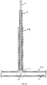
- Fig. 3 illustrates the guide tube 10 in a state inserted in the pipe 41.
- the cable 2 may be inserted in the pipe 41 together with the guide tube 10 or in this case, the cable 2 may be inserted in the guide tube 10 before inserting the guide tube 10 into the pipe 41.
- Fig. 4 illustrates the way in which the cable 2 is pushed into the tube interior 11 of the guide tube 10
- Fig. 5 illustrates the tip end of the cable 2 in a state approaching the portion to be observed 70.
- the user performs an operation of focusing and the like with the main device 3 in the state shown in Fig. 5 and displays on the display device of the main device 3 the image taken from the observation image capturing part 21.
- the use of the guide tube 10 prevents a situation where the cable 2 is bent to allow the pushing force to be dispersed when inserting the cable 2 into the pipe bore 21 thereby making it difficult for the cable 2 to be pushed in.
- the use of the guide tube 10 allows the pushing force to effectively act on the cable 2 as the advancement force of the cable 2 so to thereby force the tip end of the cable 2 to smoothly approach the portion to be observed 70.
- the burden on the user during internal observation of the pipelike structure 40 can be greatly reduced.
- the observation image capturing part 21 of the cable 2 can be easily sent deep inside the pipe 41 of the pipelike structure 40 so that the condition of the pipelike structure 40 can be certainly and promptly confirmed. Further, indications of such as the blockage of the pipe bore can be detected in advance so that appropriate measures can be taken promptly.
- the cable 2 would not be able to be further pushed in since the observation image capturing part 21 abuts against the wall face of the pipe 41 at the tee structure section 411 making it difficult for the observation image capturing part 21 of the cable 2 to approach the portion to be observed 71.
- Fig. 7 is a sectional diagram (a sectional diagram showing the guide tube 10 cut along a face in the lengthwise direction thereof so to include the tube axis) illustrating a guide tube 10 shown as the second embodiment configured to avoid the circumstances given above.
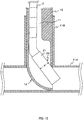
- a curved part 12 that deflects the direction in which the cable 2 advances is provided proximate the tip end of the guide tube 10.
- the advancement direction of the cable 2 is deflected to the direction toward the portion to be observed 71 at the curved part 12 when using this guide tube 10 as illustrated in Fig. 8 . Therefore, the tip end of the cable 2 can be made to smoothly approach the portion to be observed 71 by an operation of pushing in the cable 2 from outside the tube.
- the cable 2 usually includes at the tip end thereof a stiff portion (a cylindrical metal case surrounding the circumference of the observation image capturing part 21 in the present example which is hereinafter called "stiff portion 22") that lacks flexibility and that has a predetermine length (e.g., about 10 to 15 mm) for protecting the observation image capturing part 21 and the like.
- This stiff portion 22 may get stuck at the curved part 12 preventing the cable 2 from advancing. For such reason, it is recommended that the inside tube diameter at the curved part 12, for example, can be widened to allow the stiff portion 22 to smoothly pass through the curved part 12 when the cable includes such stiff portion 22.
- the inside tube diameter of the guide tube 10 at the curved part 12 can be appropriately set using, for example, the following relation.
- the wall thickness of the guide tube 10 is set to "t”
- the internal diameter of the pipe 41A is set to "a”
- the outside diameter of the guide tube 10 is set to "b” (so the internal diameter of the guide tube 10 is "b-2t")
- the angle formed by the central axis of the stiff portion 22 (central axis of the observation image capturing part 21) and the central axis of the pipe 41A is set to " ⁇ ”
- the length of the stiff portion 22 (not deformable) is set to "L”
- the margin length required for bending the cable 2 at the rear of the stiff portion 22 positioned at the tip end of the cable is set to " ⁇ ”
- the diameter of the stiff portion 22 is set to "d”
- the following equation needs to be satisfied between the above variables for allowing the stiff portion 22 to pass through. L + ⁇ ⁇ a ⁇ d * cos ⁇
- the inner tube diameter "b" of the guide tube 10 at the curved part 12 should satisfy the above equation.
- the inner tube diameter "b" of the guide tube 10 at the curved part 12 should satisfy the following equation. L + 2 ⁇ ⁇ a ⁇ d * cos ⁇ ⁇ t / sin ⁇ + b ⁇ d / sin ⁇ ⁇ t / cos ⁇ ) ) min
- the internal diameter of the guide tube 10 may be made to continuously change from the internal diameter of other parts (besides those proximate the curved part 12) to the internal diameter proximate the curved part 12 so that the cable 2 can be smoothly passed through the curved part 12.
- the tube axis of the tube interior of the guide tube 10 may be decentered toward the direction opposite the direction in which the cable 2 is deflected by the action of the curved part 12, at a portion besides that proximate the curved part 12 (proximate the tip end), as illustrated in Fig. 10 .
- the radius of curvature of the cable 2 that bends at the curved part 12 can be maximized so to reduce the friction between the cable 2 and the wall face of the pipe bore of the pipe 41 to thereby allow the cable 2 to be further smoothly inserted into the pipe bore.
- Fig. 11 is a sectional diagram (a sectional diagram showing the guide tube 10 cut along a face in the lengthwise direction thereof so to include the tube axis) illustrating a guide tube 10 shown as the third embodiment.
- the guide tube 10 of the third embodiment is a double-layered tube structure including an outside tube 10A and an inside tube 10B that is inserted into the outside tube 10A.
- the outside diameter of the outside tube 10A is substantially equal to the internal diameter of the pipe 41 to a degree that the guide tube 10 can be inserted in the pipe bore of the pipe 41 through which the cable 2 is inserted, and the internal diameter of the outside tube 10A is substantially equal to the outside diameter of the inside tube 10B to a degree that the inside tube 10B can be inserted therein.
- the inside tube 10B has the internal diameter thereof set to be substantially equal to the outside diameter of the cable 2 to a degree that the cable 2 can be inserted therein. Additionally, the tip end of the inside tube 10B has provided thereto a holding structure 15 (elastic tube, clip and the like) for holding the part proximate the tip end of the cable 2 that is inserted in the inside tube 10B.
- a holding structure 15 elastic tube, clip and the like
- the cable 2 inserted into the pipe 41 using the guide tube 10 of the third embodiment is performed in, for example, the following manner.
- the user firstly inserts the cable 2 into the inside tube 10B and then fixes the tip end of the cable 2 (periphery of the observation image capturing part 21) using the holding structure 15, as shown in Fig. 12 .
- the user inserts the outside tube 10A into the pipe bore of the pipe 41, as shown in Fig. 13 .
- the user inserts the inside tube 10B into the tube interior of the outside tube 10A with the cable 2 in a fixed state, as shown in Fig. 14 .
- the tip end of the cable 2 is fixed to the tip end of the inside tube 10B with the holding structure 15 in the above case, the pushing force applied when pushing the inside tube 10B into the tube interior of the outside tube 10A is effectively transmitted to a part proximate the tip end of the cable 2.
- the cable 2 can be made to easily approach the portion to be observed 70 without the cable 2 bending.
Landscapes
- Physics & Mathematics (AREA)
- General Physics & Mathematics (AREA)
- Astronomy & Astrophysics (AREA)
- Optics & Photonics (AREA)
- Chemical & Material Sciences (AREA)
- Life Sciences & Earth Sciences (AREA)
- Health & Medical Sciences (AREA)
- Analytical Chemistry (AREA)
- Biochemistry (AREA)
- General Health & Medical Sciences (AREA)
- Immunology (AREA)
- Pathology (AREA)
- Instruments For Viewing The Inside Of Hollow Bodies (AREA)
- Investigating Materials By The Use Of Optical Means Adapted For Particular Applications (AREA)
Abstract
Description
- The present invention relates to a guide tube for guiding a cable of an internal observation device and a cable guiding method. In particular, the present invention relates to a technology for assisting to insert into a pipe bore a cable provided with an observation image capturing part for use during an internal observation of a pipelike structure.
- To perform a cost effective internal observation of a pipe,
PTL 1 discloses that during internal observation of a pipe using an internal observation device such as a fiberscope or a videoscope, a flexible guide path through which a remote macroscopic inspection device passes is advanced and lead beforehand up to an entrance or proximate the entrance of the pipe along a guide means disposed up to an entrance or proximate the entrance of the pipe to be inspected and the guide path is further advanced and passed through the pipe, and guides the remote macroscopic inspection device after a suitable time with the guide path for guiding inside the pipe for internal observation of the pipe with the remote macroscopic inspection device. Hereby the guide path is lead to the entrance of the pipe to be observed with the guiding means while avoiding the guide path from wandering into an entrance of another pipe so that the guide path is advanced to enter the entrance of the pipe to be observed, then advanced into the pipe to be observed, and thereafter the remote macroscopic inspection device is passed through the guide path to reach the inside of the pipe to be observed thereby allowing internal observation of the pipe with the remote macroscopic inspection device. - [PTL 1] Japanese Laid-open Application No.
H10-132187 - Cables for internal observation equipped to internal observation devices are continuing to become thinner in recent years and those having a diameter of a few millimeters have come out these days. However, the rigidity of cables has decreased along with the thinning of the cables which in turn are being the cause of issues. That is, during internal observation of the
pipe 41, when thecable 2 is pushed in from thepipe 41 opening so that the observationimage capturing part 21 that is provided to the tip end approaches the portion to be observed 70, thecable 2 would bend at a portion between the part between thecable 2 and the wall face of the pipe bore of thepipe 41 so to contact the inner wall face. And hereby the pushing force of thecable 2 is dispersed so that the pushing force is not well transmitted as the force to allow thecable 2 to proceed and thus making it difficult for the observationimage capturing part 21 to approach the portion to be observed 70, as illustrated inFig. 15 . - The present invention has been made in view of the above circumstances and an objective thereof is to provide a guide tube for guiding a cable of an internal observation device and a cable guiding method that allows the observation image capturing part provided to the tip end of the cable of the internal observation device to smoothly approach the portion to be observed.
- A main aspect of the present invention for achieving the above objective is a guide tube that guides a cable of an internal observation device, including the guide tube assisting to insert into a pipe bore a cable of an internal observation device, the cable being pushed into the pipe bore to force an observation image capturing part provided proximate a tip end of the cable to approach a portion to be observed when performing internal observation of the pipe bore of a pipelike structure with the internal observation device; and having a structure such that an outside diameter of the guide tube is substantially equal to an internal diameter of the pipe bore to a degree that the guide tube can be inserted in the pipe bore, and an internal diameter of the guide tube is substantially equal to an outside diameter of the cable to a degree that the cable can be inserted therein..
- The present invention can prevent the cable from bending that allows the pushing force to be dispersed when the cable is pushed and inserted into the pipe bore thereby making it difficult for the cable to be smoothly pushed in. Further, according to the present invention, the pushing force can effectively act on the cable as the advancement force of the cable so that the tip end of the cable can smoothly approach the portion to be observed. Hereby, the burden on the user during an internal observation of the pipelike structure can be greatly relieved. Additionally, the observation image capturing part of the cable can be easily sent deep inside the pipe of the pipelike structure so that the condition of the pipelike structure can be certainly and promptly confirmed. Further, indications of such as the blockage of the pipe bore can be detected in advance so that appropriate measures can be taken promptly.
- Another aspect of the present invention includes the above guide tube that has a curved part included proximate a tip end of the guide tube, the curved part being configured to deflect a direction in which the tip end of the cable that is inserted in a tube interior of the guide tube is directed.
- According to the present invention, the direction in which the cable advances when pushing in the cable is deflected toward the direction of the portion to be observed at the curved portion so that even when, for example, the cable needs to pass through the tee structure section of the pipe, the tip end of the cable can be made to pass through the tee structure section to smoothly approach the portion to be observed by a pushing operation from outside the pipe.
- Another aspect of the present invention includes the above guide tube that has an internal diameter proximate the curved part made greater than internal diameters of other parts.
- According to the present invention, even when the cable includes a stiff portion of a predetermined length, the cable can be passed through without the stiff portion being stuck at the curved portion so that the cable can be smoothly inserted through the pipe bore.
- Another aspect of the present invention includes the above guide tube that has the internal diameter of the guide tube continuously change from the internal diameter of other parts to the internal diameter proximate the curved part.
- The cable can be smoothly passed through the curved portion by avoiding a discontinuous portion to be formed to the portion where the internal diameter changes.
- Another aspect of the present invention includes the above guide tube that has a tube axis of the tube interior decentered toward a direction opposite the direction in which the tip end of the cable is deflected at a portion besides the portion proximate the tip end of the guide tube.
- According to the present invention, even when the cable should bend at the curved portion of the pipe bore so to reduce the radius of curvature of the cable, the frictional force operating between the cable and the wall face of the pipe bore of the piping decreases by allowing the cable to slide in the guide tube. And further, the pushing force can be effectively transmitted to the cable as the advancement force of the cable for the cable to be further smoothly inserted into the pipe bore by avoiding deformation of the cable.
- Another aspect of the present invention includes the above guide tube wherein the guide tube includes an outside tube and an inside tube that is configured to be inserted in the outside tube, the outside tube has an outside diameter substantially equal to the internal diameter of the pipe bore to a degree that the outside tube can be inserted in the pipe bore, and an internal diameter of the outside tube is substantially equal to an outside diameter of the inside tube to a degree that the outside tube can have the inside tube inserted therein, the inside tube has an internal diameter substantially equal to the outside diameter of the cable to a degree that the cable can be inserted therein, and the inside tube has at a tip end thereof a holding structure for holding a part proximate the tip end of the cable that is inserted in a tube interior thereof.
- Fixing the cable to the tip end of the inside tube with a holding structure allows a pushing force to be effectively transmitted to areas proximate the tip end of the cable when the inside tube is pushed into the outside tube. In this way, the portion of the cable to which a large frictional force acts, the portion being apart from the insert hole, can pass through without the cable bending so that the cable can be smoothly advanced to approach the portion to be observed also in the case of observing a portion distant from the insert hole using a long cable.
- Other problems disclosed in the present application and the means for solving such problems will become clear from the description in the detailed description of the invention and the drawings attached.
- According to the present invention, the observation image capturing part that is provided to the tip end of the cable of the internal observation device can be made to smoothly approach the portion to be observed.
-
- [
Fig. 1 ]
Fig. 1 is a diagram illustrating a schematic configuration of theinternal observation device 1. - [
Fig. 2 ]
Fig. 2 is a sectional diagram of aguide tube 10 shown as the first embodiment. - [
Fig. 3 ]
Fig. 3 is a diagram illustrating theguide tube 10 in a state inserted in thepipe 41. - [
Fig. 4 ]
Fig. 4 is a diagram illustrating the way in which thecable 2 is pushed into thetube interior 11 of theguide tube 10. - [
Fig. 5 ]
Fig. 5 is a diagram illustrating the tip end of thecable 2 in a state approaching the portion to be observed 70. - [
Fig. 6 ]
Fig. 6 is a diagram illustrating the way in which the tip end of thecable 2 abuts against the wall face of thepipe 41 at the tee structure section. - [
Fig. 7] Fig. 7 is a sectional diagram of aguide tube 10 shown as the second embodiment. - [
Fig. 8 ]
Fig. 9 is a diagram explaining the way in which theguide tube 10 shown as the second embodiment acts. - [
Fig. 9 ]
Fig. 9 is a diagram illustrating the method of setting the internal diameter of theguide tube 10. - [
Fig. 10 ]
Fig. 10 is a diagram illustrating an example of theguide tube 10 having the tube axis of thetube interior 11 decentered. - [
Fig. 11 ]
Fig. 11 is a sectional diagram of aguide tube 10 shown as the third embodiment. - [
Fig. 12 ]
Fig. 12 is a diagram illustrating thecable 2 in a state inserted in theinside tube 10B. - [
Fig. 13 ]
Fig. 13 is a diagram illustrating theoutside tube 10A in a state inserted in the pipe bore of thepipe 41. - [
Fig. 14 ]
Fig. 14 is a diagram illustrating theinside tube 10B in a state inserted in theoutside tube 10A. - [
Fig. 15 ]
Fig. 15 is a diagram illustrating thecable 2 bending inside the pipe bore. - The following describes in detail an embodiment with reference to the drawings. In the following description, the same or similar parts are attached similar reference numbers and duplicate explanation thereof may be omitted.
-
Fig. 1 illustrates a schematic configuration of the internal observation device 1 (videoscope, fiberscope and the like) which are used for internal observation of a pipelike structure 40 (includingpipes guide tube 10 shown as the first embodiment. - As illustrated in
Fig. 1 , theinternal observation device 1 includes acable 2 provided with an observationimage capturing part 21 proximate one end thereof (hereinafter also called "tip end") and amain device 3 to which the other end (hereinafter also called "rear end") of thecable 2 is connected. - The
main device 3 includes a central processing device (CPU, MPU and the like), a memory (ROM, RAM and the like), a display device 5 (liquid crystal panel, organic EL panel and the like) and an input device 6 (keypad, touch panel and the like.) And an image based on the observation image or an image signal supplied from the observationimage capturing part 21 and transmitted through thecable 2 is reproduced and output. - When the
internal observation device 1 is, for example, a videoscope, the observationimage capturing part 21 includes, for example, a solid-state image sensing device (charge-coupled device (CCD), complementary metal oxide semiconductor (CMOS) and the like), and thecable 2 is, for example, a jacket coated metal cable that transmits to themain device 3 electrical signals of the observation image that are photoelectrically converted using the solid-state image sensing device. Further, when theinternal observation device 1 is, for example, a fiberscope, the observationimage capturing part 21 includes an optical element such as, for example, an eyepiece and the like and thecable 2 is, for example, a jacket coated optical fiber cable that transmits to themain device 3 as optical signals the observation image that has optical elements input. - During internal observation, the user inserts the
cable 2 of theinternal observation device 1 by hauling thecable 2 so that thecable 2 is pushed in from the opening of thepipe 41 that is communicated to the portion to be observed 70, in order to bring the observationimage capturing part 21 of thecable 2 closer to the portion to be observed 70 in thepipe 41. Here, theguide tube 10 functions such that thecable 2 is prevented from bending in the pipe bore of thepipe 41 as well as that the pushing force applied to thecable 2 effectively acts on thecable 2 as the advancement force toward the portion to be observed 70. -
Fig. 2 is a sectional diagram (sectional diagram showing theguide tube 10 cut along a face in the lengthwise direction thereof so to include the tube axis) illustrating aguide tube 10 shown as the first embodiment. Theguide tube 10 is in a cylindrical form. The material of theguide tube 10 is such as resin, however, the material of theguide tube 10 is preferably selected to have a sufficiently high rigidity compared to thecable 2. Further, it is preferable that the lengthwise length of theguide tube 10 is at least the same or longer than the sum length obtained by adding the length from the opening of thepipe 41 being the insert hole for thecable 2 to the section required for allowing the observationimage capturing part 21 of thecable 2 to smoothly approach the portion to be observed 70 and the length of the section that serves as the handle when inserting thecable 2 into thetube interior 11 of theguide tube 10. - The outside diameter of the
guide tube 10 is substantially equal to the internal diameter of the pipe bore of thepipe 41 to a degree that theguide tube 10 can be inserted in the pipe bore of thepipe 41 through which thecable 2 is inserted, and the internal diameter of thetube interior 11 of theguide tube 10 is substantially equal to the outside diameter of thecable 2 to a degree that thecable 2 can be inserted therein. Here, the reason for setting the outside diameter of theguide tube 10 to be substantially equal to the internal diameter of the pipe bore of thepipe 41 to a degree that the pipe bore, of thepipe 41 through which thecable 2 is to be inserted, can have inserted theguide tube 10 is to prevent theguide tube 10 itself from bending when thecable 2 is inserted into the pipe bore. Further, the reason for the internal diameter of thetube interior 11 of theguide tube 10 being substantially equal to the outside diameter of thecable 2 is to prevent thecable 2 from bending when inserting thecable 2 into theguide tube 10. - Here, the diameter of the
tube interior 11 of theguide tube 10 preferably has a dimension such that some space is secured between the outside diameter of thecable 2 so that thecable 2 can be smoothly inserted into thetube interior 11. Additionally, the material of the surface of thetube interior 11 of theguide tube 10 and the material of the surface of thecable 2 is preferably selected such that the friction coefficient between the two becomes small. - A user uses the
guide tube 10 in the following manner during an internal observation of thepipelike structure 40. To be specific, the user firstly inserts theguide tube 10 into thepipe 41 before inserting thecable 2 into thepipe 41.Fig. 3 illustrates theguide tube 10 in a state inserted in thepipe 41. Thecable 2 may be inserted in thepipe 41 together with theguide tube 10 or in this case, thecable 2 may be inserted in theguide tube 10 before inserting theguide tube 10 into thepipe 41. - Subsequently, the user pushes the
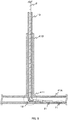
cable 2 into thetube interior 11 of theguide tube 10 so to force the tip end of thecable 2 to approach the portion to be observed 70.Fig. 4 illustrates the way in which thecable 2 is pushed into thetube interior 11 of theguide tube 10 andFig. 5 illustrates the tip end of thecable 2 in a state approaching the portion to be observed 70. The user performs an operation of focusing and the like with themain device 3 in the state shown inFig. 5 and displays on the display device of themain device 3 the image taken from the observationimage capturing part 21. - In this way, the use of the
guide tube 10 prevents a situation where thecable 2 is bent to allow the pushing force to be dispersed when inserting thecable 2 into the pipe bore 21 thereby making it difficult for thecable 2 to be pushed in. Further, the use of theguide tube 10 allows the pushing force to effectively act on thecable 2 as the advancement force of thecable 2 so to thereby force the tip end of thecable 2 to smoothly approach the portion to be observed 70. Hereby, the burden on the user during internal observation of thepipelike structure 40 can be greatly reduced. Additionally, the observationimage capturing part 21 of thecable 2 can be easily sent deep inside thepipe 41 of thepipelike structure 40 so that the condition of thepipelike structure 40 can be certainly and promptly confirmed. Further, indications of such as the blockage of the pipe bore can be detected in advance so that appropriate measures can be taken promptly. - For example, when the portion to be observed 71 exists at a place further beyond the
tee structure section 411 of thepipe 41, as illustrated inFig. 6 , thecable 2 would not be able to be further pushed in since the observationimage capturing part 21 abuts against the wall face of thepipe 41 at thetee structure section 411 making it difficult for the observationimage capturing part 21 of thecable 2 to approach the portion to be observed 71. -
Fig. 7 is a sectional diagram (a sectional diagram showing theguide tube 10 cut along a face in the lengthwise direction thereof so to include the tube axis) illustrating aguide tube 10 shown as the second embodiment configured to avoid the circumstances given above. As illustrated inFig. 7 , acurved part 12 that deflects the direction in which thecable 2 advances is provided proximate the tip end of theguide tube 10. - The advancement direction of the
cable 2 is deflected to the direction toward the portion to be observed 71 at thecurved part 12 when using thisguide tube 10 as illustrated inFig. 8 . Therefore, the tip end of thecable 2 can be made to smoothly approach the portion to be observed 71 by an operation of pushing in thecable 2 from outside the tube. - The
cable 2 usually includes at the tip end thereof a stiff portion (a cylindrical metal case surrounding the circumference of the observationimage capturing part 21 in the present example which is hereinafter called "stiff portion 22") that lacks flexibility and that has a predetermine length (e.g., about 10 to 15 mm) for protecting the observationimage capturing part 21 and the like. Thisstiff portion 22 may get stuck at thecurved part 12 preventing thecable 2 from advancing. For such reason, it is recommended that the inside tube diameter at thecurved part 12, for example, can be widened to allow thestiff portion 22 to smoothly pass through thecurved part 12 when the cable includes suchstiff portion 22. - In this case, the inside tube diameter of the
guide tube 10 at thecurved part 12 can be appropriately set using, for example, the following relation. Specifically, with reference toFig. 9 , when the wall thickness of theguide tube 10 is set to "t", the internal diameter of thepipe 41A is set to "a", the outside diameter of theguide tube 10 is set to "b" (so the internal diameter of theguide tube 10 is "b-2t"), the angle formed by the central axis of the stiff portion 22 (central axis of the observation image capturing part 21) and the central axis of thepipe 41A is set to "θ", the length of the stiff portion 22 (not deformable) is set to "L", the margin length required for bending thecable 2 at the rear of thestiff portion 22 positioned at the tip end of the cable is set to "α", and the diameter of thestiff portion 22 is set to "d", the following equation needs to be satisfied between the above variables for allowing thestiff portion 22 to pass through.
- Therefore, the inner tube diameter "b" of the
guide tube 10 at thecurved part 12 should satisfy the above equation. - And when the
stiff portion 22 is included at a mid-part of the cable, the inner tube diameter "b" of theguide tube 10 at thecurved part 12 should satisfy the following equation.
- By the way, the internal diameter of the
guide tube 10 may be made to continuously change from the internal diameter of other parts (besides those proximate the curved part 12) to the internal diameter proximate thecurved part 12 so that thecable 2 can be smoothly passed through thecurved part 12. - Further, for example, the tube axis of the tube interior of the
guide tube 10 may be decentered toward the direction opposite the direction in which thecable 2 is deflected by the action of thecurved part 12, at a portion besides that proximate the curved part 12 (proximate the tip end), as illustrated inFig. 10 . In this way, the radius of curvature of thecable 2 that bends at thecurved part 12 can be maximized so to reduce the friction between thecable 2 and the wall face of the pipe bore of thepipe 41 to thereby allow thecable 2 to be further smoothly inserted into the pipe bore. -
Fig. 11 is a sectional diagram (a sectional diagram showing theguide tube 10 cut along a face in the lengthwise direction thereof so to include the tube axis) illustrating aguide tube 10 shown as the third embodiment. As illustrated inFig. 11 , theguide tube 10 of the third embodiment is a double-layered tube structure including anoutside tube 10A and aninside tube 10B that is inserted into theoutside tube 10A. The outside diameter of theoutside tube 10A is substantially equal to the internal diameter of thepipe 41 to a degree that theguide tube 10 can be inserted in the pipe bore of thepipe 41 through which thecable 2 is inserted, and the internal diameter of theoutside tube 10A is substantially equal to the outside diameter of theinside tube 10B to a degree that theinside tube 10B can be inserted therein. Further, theinside tube 10B has the internal diameter thereof set to be substantially equal to the outside diameter of thecable 2 to a degree that thecable 2 can be inserted therein. Additionally, the tip end of theinside tube 10B has provided thereto a holding structure 15 (elastic tube, clip and the like) for holding the part proximate the tip end of thecable 2 that is inserted in theinside tube 10B. - The
cable 2 inserted into thepipe 41 using theguide tube 10 of the third embodiment is performed in, for example, the following manner. To be specific, the user firstly inserts thecable 2 into theinside tube 10B and then fixes the tip end of the cable 2 (periphery of the observation image capturing part 21) using the holdingstructure 15, as shown inFig. 12 . Subsequently, the user inserts theoutside tube 10A into the pipe bore of thepipe 41, as shown inFig. 13 . Thereafter, the user inserts theinside tube 10B into the tube interior of theoutside tube 10A with thecable 2 in a fixed state, as shown inFig. 14 . - Since the tip end of the
cable 2 is fixed to the tip end of theinside tube 10B with the holdingstructure 15 in the above case, the pushing force applied when pushing theinside tube 10B into the tube interior of theoutside tube 10A is effectively transmitted to a part proximate the tip end of thecable 2. Hereby, thecable 2 can be made to easily approach the portion to be observed 70 without thecable 2 bending. - The above described embodiments are simply for facilitating the understanding of the present invention and are not in any way to be construed as limiting the present invention. It is a matter of course that the present invention may variously be changed or altered without departing from its spirit and encompasses equivalents thereof.
- 1 internal observation device, 2 cable, 3 main device, 5 display device, 6 input device, 10 guide tube, 11 tube interior, 12 curved part, 15 holding structure, 21 observation image capturing part, 22 stiff portion, 40 pipelike structure, 41 pipe, 41A, 41B pipe, 70, 71 portion to be observed
Claims (10)
- A guide tube that guides a cable of an internal observation device, comprising:the guide tube assisting to insert into a pipe bore a cable of an internal observation device, the cable being pushed into the pipe bore to force an observation image capturing part provided proximate a tip end of the cable to approach a portion to be observed when performing internal observation of the pipe bore of a pipelike structure with the internal observation device; andan outside diameter of the guide tube that is substantially equal to an internal diameter of the pipe bore to a degree that the guide tube can be inserted in the pipe bore, and an internal diameter of the guide tube that is substantially equal to an outside diameter of the cable to a degree that the cable can be inserted therein.
- A guide tube that guides a cable of an internal observation device according to claim 1, wherein
a curved part is included proximate a tip end of the guide tube, the curved part being configured to deflect a direction in which the tip end of the cable that is inserted in a tube interior of the guide tube is directed. - A guide tube that guides a cable of an internal observation device according to claim 2, wherein
an internal diameter proximate the curved part is made greater than internal diameters of other parts. - A guide tube that guides a cable of an internal observation device according to claim 3, wherein
the internal diameter of the guide tube continuously changes from the internal diameter of other parts to the internal diameter proximate the curved part. - A guide tube that guides a cable of an internal observation device according to claim 2, wherein
a tube axis of the tube interior is decentered toward a direction opposite the direction in which the tip end of the cable is deflected at a portion besides the portion proximate the tip end of the guide tube. - A guide tube that guides a cable of an internal observation device according to claim 1, wherein
the guide tube includes an outside tube and an inside tube that is configured to be inserted in the outside tube,
the outside tube has an outside diameter substantially equal to the internal diameter of the pipe bore to a degree that the outside tube can be inserted in the pipe bore, and an internal diameter of the outside tube is substantially equal to an outside diameter of the inside tube to a degree that the outside tube can have the inside tube inserted therein,
the inside tube has an internal diameter substantially equal to the outside diameter of the cable to a degree that the cable can be inserted therein, and
the inside tube has at a tip end thereof a holding structure for holding a part proximate the tip end of the cable that is inserted in a tube interior thereof. - A cable guiding method of an internal observation device, including inserting into a pipe bore the cable of the internal observation device, the cable being pushed into the pipe bore to force an observation image capturing part provided proximate a tip end of the cable to approach a portion to be observed when performing internal observation of the pipe bore of a pipelike structure with the internal observation device, comprising:inserting into the pipe bore a guide tube having an outside diameter that is substantially equal to an internal diameter of the pipe bore to a degree that the guide tube can be inserted in the pipe bore, and an internal diameter that is substantially equal to an outside diameter of the cable; andinserting the cable into a tube interior of the guide tube from an outside of the pipe bore.
- A cable guiding method according to claim 7, wherein
the guide tube includes a curved part proximate a tip end of the guide tube, the curved part being configured to deflect a direction in which the tip end of the cable that is inserted in the tube interior of the guide tube is directed. - A cable guiding method according to claim 8, wherein
a tube axis of the tube interior is decentered toward a direction opposite a direction in which the cable is deflected at a portion besides a portion proximate the tip end of the guide tube. - A cable guiding method according to claim 7, wherein
the guide tube includes an outside tube and an inside tube that is configured to be inserted in the outside tube,
the outside tube has an outside diameter substantially equal to the internal diameter of the pipe bore to a degree that the outside tube can be inserted in the pipe bore, and an internal diameter of the outside tube is substantially equal to an outside diameter of the inside tube to a degree that the outside tube can have the inside tube inserted therein,
the inside tube has an internal diameter substantially equal to the outside diameter of the cable to a degree that the cable can be inserted therein, and
the inside tube has at a tip end thereof a holding structure for holding a part proximate the tip end of the cable that is inserted in a tube interior thereof, the method further comprising
inserting the cable into the inside tube and holding with the holding structure the part proximate the tip end of the cable and
inserting into the outside tube the inside tube having the cable fixed thereto.
Applications Claiming Priority (1)
| Application Number | Priority Date | Filing Date | Title |
|---|---|---|---|
| PCT/JP2014/055616 WO2015132902A1 (en) | 2014-03-05 | 2014-03-05 | Guide tube for guiding cable for inside observation device and method for guiding cable |
Publications (2)
| Publication Number | Publication Date |
|---|---|
| EP3115825A1 true EP3115825A1 (en) | 2017-01-11 |
| EP3115825A4 EP3115825A4 (en) | 2017-02-15 |
Family
ID=54054739
Family Applications (1)
| Application Number | Title | Priority Date | Filing Date |
|---|---|---|---|
| EP14884731.2A Withdrawn EP3115825A4 (en) | 2014-03-05 | 2014-03-05 | Guide tube for guiding cable for inside observation device and method for guiding cable |
Country Status (5)
| Country | Link |
|---|---|
| US (1) | US20170075102A1 (en) |
| EP (1) | EP3115825A4 (en) |
| JP (1) | JP5823650B1 (en) |
| SG (1) | SG11201607348TA (en) |
| WO (1) | WO2015132902A1 (en) |
Families Citing this family (2)
| Publication number | Priority date | Publication date | Assignee | Title |
|---|---|---|---|---|
| US11333613B2 (en) | 2015-04-07 | 2022-05-17 | The Boeing Company | Apparatus and methods of inspecting a wire segment |
| JP7626386B2 (en) * | 2020-10-02 | 2025-02-04 | オリエンタル白石株式会社 | Intra-sheath observation method using an endoscope |
Family Cites Families (10)
| Publication number | Priority date | Publication date | Assignee | Title |
|---|---|---|---|---|
| DE2263148C3 (en) * | 1972-12-22 | 1979-12-20 | Siemens Ag, 1000 Berlin Und 8000 Muenchen | Equipment for the inspection and repair of pipes in steam generators of nuclear reactors |
| JP3578572B2 (en) * | 1996-10-25 | 2004-10-20 | 株式会社日立製作所 | Pipe internal view method and equipment used for the method |
| US8289385B2 (en) * | 2009-02-13 | 2012-10-16 | Seektech, Inc. | Push-cable for pipe inspection system |
| JP5253027B2 (en) * | 2008-07-23 | 2013-07-31 | オリンパス株式会社 | Endoscope guide tube and endoscope system |
| JP5430101B2 (en) * | 2008-09-02 | 2014-02-26 | オリンパス株式会社 | Guide tube and endoscope system |
| JP5555016B2 (en) * | 2010-03-10 | 2014-07-23 | オリンパス株式会社 | Guide tube for bent tube passage |
| JP5555019B2 (en) * | 2010-03-15 | 2014-07-23 | オリンパス株式会社 | Guide tube |
| JP5606812B2 (en) * | 2010-07-05 | 2014-10-15 | オリンパス株式会社 | Endoscope guide tube |
| WO2012016321A1 (en) * | 2010-08-05 | 2012-02-09 | Liqui-Force Sewer Services, Inc. | Method of inspecting and preparing a pipeline |
| US9448376B2 (en) * | 2012-05-01 | 2016-09-20 | SeeScan, Inc. | High bandwidth push cables for video pipe inspection systems |
-
2014
- 2014-03-05 WO PCT/JP2014/055616 patent/WO2015132902A1/en not_active Ceased
- 2014-03-05 SG SG11201607348TA patent/SG11201607348TA/en unknown
- 2014-03-05 JP JP2015512423A patent/JP5823650B1/en active Active
- 2014-03-05 US US15/123,562 patent/US20170075102A1/en not_active Abandoned
- 2014-03-05 EP EP14884731.2A patent/EP3115825A4/en not_active Withdrawn
Also Published As
| Publication number | Publication date |
|---|---|
| EP3115825A4 (en) | 2017-02-15 |
| JP5823650B1 (en) | 2015-11-25 |
| WO2015132902A1 (en) | 2015-09-11 |
| JPWO2015132902A1 (en) | 2017-03-30 |
| SG11201607348TA (en) | 2016-10-28 |
| US20170075102A1 (en) | 2017-03-16 |
Similar Documents
| Publication | Publication Date | Title |
|---|---|---|
| JP3831683B2 (en) | Bending prevention of flexible tube insertion part of endoscope with outer sheath | |
| CN103764010B (en) | endoscope | |
| EP2740400A1 (en) | Bending tube and medical instrument | |
| US20160073861A1 (en) | Sheath for endoscope | |
| CN104349704A (en) | Endoscope | |
| US9974428B2 (en) | Endoscope | |
| CN106163362A (en) | Endoscope | |
| US10088668B2 (en) | Endoscope | |
| JP5555016B2 (en) | Guide tube for bent tube passage | |
| US20170075102A1 (en) | Guide tube for guiding cable of internal observation device and cable guiding method | |
| EP3143921A1 (en) | Adapter for instrument and manipulator system for operation | |
| US20060161046A1 (en) | Front end structure of endoscope | |
| CN109068942B (en) | Medical outer sleeve | |
| US20170067592A1 (en) | Channeled tube inspection device | |
| JP5555019B2 (en) | Guide tube | |
| CN205181288U (en) | Endoscopy system | |
| US11375880B2 (en) | Rigid endoscope | |
| JP2011224115A (en) | Endoscope | |
| DE202010006943U1 (en) | endoscope | |
| JP6502744B2 (en) | Endoscope device | |
| JP5933995B2 (en) | Flexible endoscope with insertion shape detection function | |
| JP2007130374A (en) | Guide tube for endoscope and endoscope apparatus | |
| EP3366189A1 (en) | Endoscope | |
| EP3078320B1 (en) | Wire device and endoscope | |
| US20150153006A1 (en) | Damage evident transducer cable |
Legal Events
| Date | Code | Title | Description |
|---|---|---|---|
| PUAI | Public reference made under article 153(3) epc to a published international application that has entered the european phase |
Free format text: ORIGINAL CODE: 0009012 |
|
| STAA | Information on the status of an ep patent application or granted ep patent |
Free format text: STATUS: REQUEST FOR EXAMINATION WAS MADE |
|
| 17P | Request for examination filed |
Effective date: 20160930 |
|
| AK | Designated contracting states |
Kind code of ref document: A1 Designated state(s): AL AT BE BG CH CY CZ DE DK EE ES FI FR GB GR HR HU IE IS IT LI LT LU LV MC MK MT NL NO PL PT RO RS SE SI SK SM TR |
|
| AX | Request for extension of the european patent |
Extension state: BA ME |
|
| A4 | Supplementary search report drawn up and despatched |
Effective date: 20170118 |
|
| RIC1 | Information provided on ipc code assigned before grant |
Ipc: G01N 21/954 20060101ALI20170112BHEP Ipc: G02B 23/24 20060101AFI20170112BHEP Ipc: G01N 21/88 20060101ALI20170112BHEP |
|
| DAX | Request for extension of the european patent (deleted) | ||
| STAA | Information on the status of an ep patent application or granted ep patent |
Free format text: STATUS: THE APPLICATION IS DEEMED TO BE WITHDRAWN |
|
| 18D | Application deemed to be withdrawn |
Effective date: 20181002 |