EP3115814A1 - Cable gripping structure and optical fiber connector - Google Patents
Cable gripping structure and optical fiber connector Download PDFInfo
- Publication number
- EP3115814A1 EP3115814A1 EP15758040.8A EP15758040A EP3115814A1 EP 3115814 A1 EP3115814 A1 EP 3115814A1 EP 15758040 A EP15758040 A EP 15758040A EP 3115814 A1 EP3115814 A1 EP 3115814A1
- Authority
- EP
- European Patent Office
- Prior art keywords
- optical fiber
- cable
- fiber cable
- support walls
- mounting part
- Prior art date
- Legal status (The legal status is an assumption and is not a legal conclusion. Google has not performed a legal analysis and makes no representation as to the accuracy of the status listed.)
- Withdrawn
Links
- 239000013307 optical fiber Substances 0.000 title claims abstract description 185
- 230000003287 optical effect Effects 0.000 description 7
- 230000008878 coupling Effects 0.000 description 6
- 238000010168 coupling process Methods 0.000 description 6
- 238000005859 coupling reaction Methods 0.000 description 6
- 238000004873 anchoring Methods 0.000 description 5
- POIUWJQBRNEFGX-XAMSXPGMSA-N cathelicidin Chemical compound C([C@@H](C(=O)N[C@@H](CCCNC(N)=N)C(=O)N[C@@H](CCCCN)C(=O)N[C@@H](CO)C(=O)N[C@@H](CCCCN)C(=O)N[C@@H](CCC(O)=O)C(=O)N[C@@H](CCCCN)C(=O)N[C@@H]([C@@H](C)CC)C(=O)NCC(=O)N[C@@H](CCCCN)C(=O)N[C@@H](CCC(O)=O)C(=O)N[C@@H](CC=1C=CC=CC=1)C(=O)N[C@@H](CCCCN)C(=O)N[C@@H](CCCNC(N)=N)C(=O)N[C@@H]([C@@H](C)CC)C(=O)N[C@@H](C(C)C)C(=O)N[C@@H](CCC(N)=O)C(=O)N[C@@H](CCCNC(N)=N)C(=O)N[C@@H]([C@@H](C)CC)C(=O)N[C@@H](CCCCN)C(=O)N[C@@H](CC(O)=O)C(=O)N[C@@H](CC=1C=CC=CC=1)C(=O)N[C@@H](CC(C)C)C(=O)N[C@@H](CCCNC(N)=N)C(=O)N[C@@H](CC(N)=O)C(=O)N[C@@H](CC(C)C)C(=O)N[C@@H](C(C)C)C(=O)N1[C@@H](CCC1)C(=O)N[C@@H](CCCNC(N)=N)C(=O)N[C@@H]([C@@H](C)O)C(=O)N[C@@H](CCC(O)=O)C(=O)N[C@@H](CO)C(O)=O)NC(=O)[C@H](CC=1C=CC=CC=1)NC(=O)[C@H](CC(O)=O)NC(=O)CNC(=O)[C@H](CC(C)C)NC(=O)[C@@H](N)CC(C)C)C1=CC=CC=C1 POIUWJQBRNEFGX-XAMSXPGMSA-N 0.000 description 4
- 230000006835 compression Effects 0.000 description 3
- 238000007906 compression Methods 0.000 description 3
- 230000000052 comparative effect Effects 0.000 description 2
- 230000000694 effects Effects 0.000 description 2
- 238000003780 insertion Methods 0.000 description 2
- 230000037431 insertion Effects 0.000 description 2
- 239000011800 void material Substances 0.000 description 2
- 238000005253 cladding Methods 0.000 description 1
- 239000012141 concentrate Substances 0.000 description 1
- 230000003247 decreasing effect Effects 0.000 description 1
- 238000012986 modification Methods 0.000 description 1
- 230000004048 modification Effects 0.000 description 1
Images



Classifications
-
- G—PHYSICS
- G02—OPTICS
- G02B—OPTICAL ELEMENTS, SYSTEMS OR APPARATUS
- G02B6/00—Light guides; Structural details of arrangements comprising light guides and other optical elements, e.g. couplings
- G02B6/24—Coupling light guides
- G02B6/36—Mechanical coupling means
- G02B6/38—Mechanical coupling means having fibre to fibre mating means
- G02B6/3801—Permanent connections, i.e. wherein fibres are kept aligned by mechanical means
- G02B6/3806—Semi-permanent connections, i.e. wherein the mechanical means keeping the fibres aligned allow for removal of the fibres
-
- G—PHYSICS
- G02—OPTICS
- G02B—OPTICAL ELEMENTS, SYSTEMS OR APPARATUS
- G02B6/00—Light guides; Structural details of arrangements comprising light guides and other optical elements, e.g. couplings
- G02B6/24—Coupling light guides
- G02B6/36—Mechanical coupling means
- G02B6/38—Mechanical coupling means having fibre to fibre mating means
- G02B6/3807—Dismountable connectors, i.e. comprising plugs
- G02B6/381—Dismountable connectors, i.e. comprising plugs of the ferrule type, e.g. fibre ends embedded in ferrules, connecting a pair of fibres
- G02B6/3818—Dismountable connectors, i.e. comprising plugs of the ferrule type, e.g. fibre ends embedded in ferrules, connecting a pair of fibres of a low-reflection-loss type
- G02B6/3821—Dismountable connectors, i.e. comprising plugs of the ferrule type, e.g. fibre ends embedded in ferrules, connecting a pair of fibres of a low-reflection-loss type with axial spring biasing or loading means
-
- G—PHYSICS
- G02—OPTICS
- G02B—OPTICAL ELEMENTS, SYSTEMS OR APPARATUS
- G02B6/00—Light guides; Structural details of arrangements comprising light guides and other optical elements, e.g. couplings
- G02B6/24—Coupling light guides
- G02B6/36—Mechanical coupling means
- G02B6/38—Mechanical coupling means having fibre to fibre mating means
- G02B6/3807—Dismountable connectors, i.e. comprising plugs
- G02B6/3869—Mounting ferrules to connector body, i.e. plugs
- G02B6/387—Connector plugs comprising two complementary members, e.g. shells, caps, covers, locked together
-
- G—PHYSICS
- G02—OPTICS
- G02B—OPTICAL ELEMENTS, SYSTEMS OR APPARATUS
- G02B6/00—Light guides; Structural details of arrangements comprising light guides and other optical elements, e.g. couplings
- G02B6/24—Coupling light guides
- G02B6/36—Mechanical coupling means
- G02B6/38—Mechanical coupling means having fibre to fibre mating means
- G02B6/3807—Dismountable connectors, i.e. comprising plugs
- G02B6/3887—Anchoring optical cables to connector housings, e.g. strain relief features
- G02B6/3888—Protection from over-extension or over-compression
-
- G—PHYSICS
- G02—OPTICS
- G02B—OPTICAL ELEMENTS, SYSTEMS OR APPARATUS
- G02B6/00—Light guides; Structural details of arrangements comprising light guides and other optical elements, e.g. couplings
- G02B6/24—Coupling light guides
- G02B6/36—Mechanical coupling means
- G02B6/38—Mechanical coupling means having fibre to fibre mating means
- G02B6/3807—Dismountable connectors, i.e. comprising plugs
- G02B6/389—Dismountable connectors, i.e. comprising plugs characterised by the method of fastening connecting plugs and sockets, e.g. screw- or nut-lock, snap-in, bayonet type
- G02B6/3893—Push-pull type, e.g. snap-in, push-on
Definitions
- the cable gripping structure of an embodiment of the present invention is a cable gripping structure for securing an optical fiber cable in an optical fiber connector, which possesses a base part and a pair of support walls disposed opposite one another on the base part. Blade parts for gripping the optical fiber cable are disposed on the pair of support walls at tip ends thereof and separated from bases of the support walls.
- the optical fiber connector 13 is equipped with a cylindrical collar 14 that extends in the lengthwise direction (X-axis direction) and a ferrule 16 that is disposed at a tip of 14a of the collar.
- the collar 14 possesses a through hole 14c at a back end 14d thereof for inserting an optical fiber that has been inserted from the back end of the connector body 2.
- a spring 19 is disposed at the back end 14d of the collar 14, encircling the collar 14. This spring 19 exerts elastic force toward the connector tip end of the collar 14 inside the base 11, thereby keeping pressure on the ferrule 16 and maintaining contact with a ferrule that is built into another optical fiber connector that is to be coupled with the optical fiber connector 1.
- the connecting optical fiber and the optical fiber in the optical fiber cable 100 that has been inserted from the back end of the connector body 2 are in a state abutted against, and optically connected to, one another in the core anchoring part. Inserting the cap 18 in this state anchors the optical fiber in the optical fiber cable 100 and the connecting optical fiber.
- the state of the optical fiber connector 1 being "installed" on the end of an optical fiber indicates a state in which the optical fiber has been anchored by connecting the connector body 2 to the optical fiber and coupling the cover part 5 with the mounting part 3, whereby the optical fiber connecter 1 has been completely attached to the end of the optical fiber and can be connected to another connector.
- the upper wall 21, which is one of the surfaces that constitutes the outer circumference, is notched out at the back end of the base part 11, and the mounting part 3, in which the optical fiber cable 100 is installed, is formed by the floor wall 31 and side walls 32, 33.
- the mounting part 3 is for mounting an optical fiber cable 100 that is disposed along the lengthwise direction of the mounting part 3, wherein the optical fiber cable 100 is disposed at the back end 3b and the optical fiber is disposed at the front end 3 a with the cladding of the optical fiber cable 100 removed.
- the mounting part 3, as shown in FIG. 2 has a U-shape in cross-section, which is open in the upward direction, extending rearward in the lengthwise direction from a back end 12c of the shell 12 of the connector body 2.
- the mounting part 3 is equipped with a floor wall 31 disposed on the bottom and side walls 32, 33 opposing each other in the width direction.
- a pair of grooves 34a, 34b are formed on the left and right, leaving a center portion, toward the back in the floor wall surface 31 a on the upper surface of the floor wall 31.
- the floor surface 35 has a shape toward the back of the floor wall surface 31 a in which the center portion protrudes upward in the left and right directions.
- the protruding portion constitutes a pressing part 36, described below.
- An insertion hole 3c is formed at the back end 3a side of the mounting part 3 that communicates to the core anchoring part, so that an optical fiber installed in the mounting part 3 is inserted passing therethrough.
- the cable gripping structure 6 formed in the cover part 5 is equipped with a pair of support walls 63, 64, provided with a base part 62 as the base end thereof, and blades 65,66 that are formed toward tip ends 63 a, 64a of the support walls 63, 64.
- the area toward the back end 51a of the upper wall 51 is constructed as a base part 62.
- the portion of the base part 62 between the support walls 63, 64 is formed to protrude from the inner surface 61b of the upper wall 51 toward the tips 63a, 64a of the support walls 63, 64.
- the blades 65, 66 are disposed at the tips 63a, 64a of the support walls 63, 64, separated from the base ends thereof. Specifically, the blades 65, 66 extend in the vertical direction from a specified height away from the base 62 (edge 62 of the base 62) to the tips of the support walls 63, 64. The edge 62a of the base 62 (i.e., the base end of the support wall 63, 64) and ends 65c, 66c on the base 62 end of the blades 65, 66 are separated from one another.
- boundary 67a, 67b between the thin part 63d, 64d and thick part 63e, 64e is formed at a height position between the base end of the of the support wall 63, 64 and the end 65c, 66c of the blade 65, 66 on the base 62 end (in the height range where the blades 65, 66 are not formed on the support walls 63, 64), but may also be formed at the same height position of the end of the blades 65, 66 on the base 62 end or a position slightly above this.
- optical fiber cables 100 have been installed in the cable gripping structure 6 in the optical fiber connector 1.
- FIG. 6(c) is the state in which a large-diameter optical fiber cable 101 has been gripped, that is, a case is shown where the cover part 5 and mounting part 3 are coupled in a state in which the large-diameter optical fiber cable 101 has been disposed on the pressing part 36.
- the optical fiber cable 101 is gripped by the blades 65, 66 toward the bottom of the long sides 101a of the optical fiber cable 101.
- the operation of coupling the cover part 5 and the mounting part 3 gradually presses the optical fiber cable 101 with the pressing part 36, until it is pushed all the way to the base 62.
- the pair of support walls 63, 64 possess thin parts 63d, 64d formed with a smaller wall thickness toward the tips 63a, 64 end and thick parts 63e, 64e formed with a larger wall thickness toward the base ends of the support walls 63, 64. Since making the base ends of the support walls 63, 64 from thick parts 63e, 64e makes the bearing resistance from the support walls greater than when the entire support wall is made thin, the gripping force from the blades 65, 66 can be increased. Thus, when inserting a small-diameter optical fiber cable 102, the gripping force on the small-diameter optical fiber cable 102 can be made even greater. Additionally, making the tips 63a, 64a ends of the support walls 63, 64 as thin parts 63d, 64d keeps the pressing force needed in the compression operation from getting too high compared with when the entire support wall is thick.
Landscapes
- Physics & Mathematics (AREA)
- General Physics & Mathematics (AREA)
- Optics & Photonics (AREA)
- Mechanical Coupling Of Light Guides (AREA)
Abstract
Description
- An embodiment of the present invention relates to a cable gripping structure and optical fiber connector.
- In the past, it was known that, when installing optical fiber connectors on optical fiber cables of multiple different sizes of outside diameter, optical fiber holders were employed that could be affixed to the optical fiber connector. For example, an optical fiber holder is disclosed in Japanese Unexamined Patent Application Publication No.
2010-197553 - Patent Document 1: Japanese Unexamined Patent Application Publication No.
2010-197553 - However, with the conventional optical fiber holder, in order for an optical cable to be gripped along an entire height direction, the protrusions formed in the wall surfaces were contiguously formed from the base of the wall surface to the tip thereof. In this case, the protrusions functioned as ribs, making it difficult for the pair of wall surfaces to deform. Additionally, when gripping a large diameter cable, the wall surfaces would deform completely from the base end. Therefore, when protrusions were designed for a small diameter cable, for example, there was a risk that it would be difficult to insert a large diameter cable. On the other hand, when protrusions were designed for a large diameter cable, there was a risk that it would be difficult to suitably grip a small diameter cable. Consequently, there was a demand for a cable gripping structure and optical fiber connector with improved operability that could suitably grip optical fiber cables of multiple various diameters.
- The cable gripping structure of an embodiment of the present invention is a cable gripping structure for securing an optical fiber cable in an optical fiber connector, which possesses a base part and a pair of support walls disposed opposite one another on the base part. Blade parts for gripping the optical fiber cable are disposed on the pair of support walls at tip ends thereof and separated from bases of the support walls.
- In the cable gripping structure of such an embodiment, the blade parts for gripping the optical fiber cable are disposed at the tips of the support walls, separated from the bases thereof. Therefore, even in a situation in which a dimension between the blade parts has been set to be able to adequately grip a small-diameter optical fiber cable, if a large-diameter optical fiber cable is inserted, the blades need not bite greatly into the cable. Therefore, less force is required to insert the optical fiber cable than in cases wherein the blade parts are contiguously formed from the bases. In this way, the cable gripping structure can suitably grip optical fiber cables of multiple various diameters and operability can be improved.
- Additionally, in another cable gripping structure embodiment, the blade parts can grip a first cable, as well as a second cable in which a dimension of a long side or short side in cross-section thereof is smaller than that of the first cable, and a length dimension of the blade parts is equal to or greater than the dimension of the long side in cross-section of the second cable and may be less than the dimension of the long side in cross-section of the first cable.
- Additionally, in another cable gripping structure embodiment, the pair of support walls may possess a thin part, in which a wall thickness formed toward the tip end of the support wall is small, and a thick part, in which a wall thickness formed toward the base end of the support wall is greater than that of the thin part.
- Additionally, in another cable gripping structure embodiment, a boundary part between the thin part and thick part may be formed between the base of the support wall and the blade part.
- Additionally, the optical fiber connector of an embodiment of the present invention is an optical fiber connector into which an end of an optical fiber cable is installed, which is equipped with a connector body in which a mounting part is formed for mounting the optical fiber cable, and a cover part that couples with the mounting part. The mounting part is formed by at least one surface of a back end portion of the connector body being notched out. The cover part is equipped with a cable gripping structure, and is disposed to be rotatable relative to the mounting part so as to cover the mounting part.
- Additionally, in another embodiment of the optical fiber connector of the present invention, a floor surface is provided in the mounting part opposite the tips of the support walls in the state with the cover part covering the mounting part, wherein a pressing part, capable of pressing the optical fiber cable, may be provided in the floor surface protruding from the floor surface and located between the pair of support walls in the state with the cover part covering the mounting part.
- Additionally, in another optical fiber connector embodiment, a protruding part may be provided in the cover part between the pair of support walls, protruding from the base ends toward the tip ends thereof.
- According to an aspect of the present invention, optical fiber cables of multiple various diameters can be suitably gripped, while improving workability.
-
-
FIG. 1 is an exploded perspective view showing an optical fiber connector of an embodiment. -
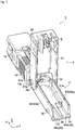
FIG. 2 is a perspective view showing an optical fiber connector in a state with the cover part open. -
FIG. 3 is a perspective view showing an optical fiber connector in a state with the cover part closed. -
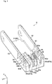
FIG. 4 is a perspective view showing the cover part. -
FIG. 5(a) is an elevation view of the cover part.FIG. 5(b) is a bottom view of the same.FIG. 5(c) is a cross sectional view of the same. -
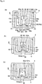
FIG. 6(a) through FIG. 6(c) are cross sectional views showing the state with the mounting part and cover part coupled. - Embodiments of the present invention will be described in detail below, referring to the attached drawings. For convenience, substantially identical elements will be assigned the same reference numbers, and descriptions thereof may be omitted. Additionally, the terms "X-axis direction," "Y-axis direction," and "Z-axis direction" are for convenience, based on the illustrated directions.
-
FIG. 1 is an exploded perspective view showing anoptical fiber connector 1 of the present 1 embodiment.FIG. 2 is a perspective view showing theoptical fiber connector 1 in a state with acover part 5 open.FIG. 3 is a perspective view showing theoptical fiber connector 1 in a state with an optical fiber cable mounted and thecover part 5 closed. As shown inFIG. 1 through FIG. 3 , theoptical fiber connector 1 is equipped withconnector body 2, which is formed with amounting part 3 at the back, in which theoptical fiber cable 100 is mounted, and thecover part 5 that couples with themounting part 3. Further, the lengthwise direction in which theoptical fiber connector 1 extends shall be the "X-axis direction" for the purposes of explanation. In the present embodiment, theoptical fiber connector 1 is installed at the tip of the optical fiber cable so that the optical fiber cable extends along the lengthwise direction in which theoptical fiber connector 1 extends. Additionally, the thickness direction of theoptical fiber connector 1 shall be the "Z-axis direction." The direction perpendicular to the X-axis direction and the Z-axis direction, namely, the width direction of theoptical fiber connector 1, shall be the "Y-axis direction." Further, the tip end of theoptical fiber connector 1 shall be the "front (positive X-axis end)," and the end in which the optical fiber cable is inserted shall be the "back (negative X-axis end)." Additionally, the side on which the operation of pressing oncap 18, described below, is performed shall be the "top (positive Z-axis side)," and the opposite side from that shall be the "bottom (negative Z-axis side)." Additionally, a central axis CL for theoptical fiber connector 1 is set extending parallel to the X-axis direction. Unless specifically noted, members described in the present application possess a planar symmetric structure with the XZ plane through which the central-axis CL passes as the plane of reference. - The
connector body 2 is equipped with abase part 11, ashell 12, and anoptical fiber connector 13. Theconnector body 2 is constituted with theoptical fiber connector 13 built into thebase part 11, so that the outer circumference of thebase part 11 is covered by theshell 12. Further, e.g., an SC-type optical connector may be used as theconnector body 2. FC-type optical connectors, ST-type optical connectors, and LC-type optical connectors are considered as other examples thereof. The explanation in this Specification shall be given using an SC-type optical connector, but this SC-type optical connector is merely an example and the invention of the present application is not limited to this kind of connector. - The
base part 11 is a rectangular tube-shaped member that extends in the lengthwise direction (X-axis direction), which is equipped with anupper wall 21 disposed on the top (positive Z-axis side), afloor wall 22 disposed on the bottom (negative Z-axis side), opposite theupper wall 21, andside walls shell 12 is a rectangular tube-shaped member that extends in the lengthwise direction, which is equipped with anupper wall 26 disposed on the top, afloor wall 27 disposed on the bottom opposite theupper wall 26, andside walls shell 12 fits onto thebase part 11 so as to cover the outer circumferential surfaces thereof at the front end, with theupper wall 28,floor wall 27, andside walls shell 12 respectively covering theupper wall 21,floor wall 22, andside walls base 11. - The
optical fiber connector 13 is equipped with acylindrical collar 14 that extends in the lengthwise direction (X-axis direction) and aferrule 16 that is disposed at a tip of 14a of the collar. Thecollar 14 possesses a throughhole 14c at aback end 14d thereof for inserting an optical fiber that has been inserted from the back end of theconnector body 2. Further, aspring 19 is disposed at theback end 14d of thecollar 14, encircling thecollar 14. Thisspring 19 exerts elastic force toward the connector tip end of thecollar 14 inside thebase 11, thereby keeping pressure on theferrule 16 and maintaining contact with a ferrule that is built into another optical fiber connector that is to be coupled with theoptical fiber connector 1. Further, an optical fiber introduction hole (not illustrated) is formed in theferrule 16 along the central axis CL, and the connecting optical fiber (not illustrated) is inserted and secured in this optical fiber introduction hole. Thisferrule 16 is coupled with thetip 14a so that the central axis aligns with thecollar 14. - An
open portion 14b is formed in thecollar 14 that opens upward (Z-axis direction), and a core anchoring part (not illustrated) is accommodated inside theopen portion 14b. Additionally, acap 18 for pressing on the core anchoring part from above is disposed in theopen portion 14b of thecollar 14.Open portions upper wall 21 of thebase 11 and theupper wall 26 of theshell 12, at locations corresponding to theopen portion 14b of thecollar 14. Consequently, thecap 18 is in a state exposed through theshell 12. - The connecting optical fiber and the optical fiber in the
optical fiber cable 100 that has been inserted from the back end of theconnector body 2 are in a state abutted against, and optically connected to, one another in the core anchoring part. Inserting thecap 18 in this state anchors the optical fiber in theoptical fiber cable 100 and the connecting optical fiber. In this Specification, the state of theoptical fiber connector 1 being "installed" on the end of an optical fiber indicates a state in which the optical fiber has been anchored by connecting theconnector body 2 to the optical fiber and coupling thecover part 5 with the mountingpart 3, whereby theoptical fiber connecter 1 has been completely attached to the end of the optical fiber and can be connected to another connector. - In the state in which the outer circumference of the
base part 11 has been completely covered by theshell 12, theupper wall 21, which is one of the surfaces that constitutes the outer circumference, is notched out at the back end of thebase part 11, and the mountingpart 3, in which theoptical fiber cable 100 is installed, is formed by thefloor wall 31 andside walls - The mounting
part 3 is for mounting anoptical fiber cable 100 that is disposed along the lengthwise direction of the mountingpart 3, wherein theoptical fiber cable 100 is disposed at theback end 3b and the optical fiber is disposed at thefront end 3 a with the cladding of theoptical fiber cable 100 removed. The mountingpart 3, as shown inFIG. 2 , has a U-shape in cross-section, which is open in the upward direction, extending rearward in the lengthwise direction from aback end 12c of theshell 12 of theconnector body 2. The mountingpart 3 is equipped with afloor wall 31 disposed on the bottom andside walls grooves floor wall 31. In other words, if thesegrooves floor surface 35, thefloor surface 35 has a shape toward the back of the floor wall surface 31 a in which the center portion protrudes upward in the left and right directions. The protruding portion constitutes apressing part 36, described below. Aninsertion hole 3c is formed at theback end 3a side of the mountingpart 3 that communicates to the core anchoring part, so that an optical fiber installed in the mountingpart 3 is inserted passing therethrough.Shaft parts cover part 5 are formed toward the front end side on theouter wall surfaces side walls latch parts 38 for coupling the mountingpart 3 and thecover part 5, when the mountingpart 3 is in a state covered by thecover part 5, are formed toward the back end in theouter wall surfaces outer wall surface 33a is not illustrated). Thelatch parts 38 are provided protruding outward from theouter wall surfaces - As shown in
FIG. 1 through FIG. 3 , thecover part 5 is for anchoring theoptical fiber cable 100 in theoptical fiber connector 1 when in the state coupled with the mountingpart 3 and covering the mountingpart 3 from above. Thecover part 5 is equipped with a rectangular plate-shapedupper wall 51 andside walls upper wall 51, and possesses acable gripping structure 6 between theside walls optical fiber cable 100. Circular throughholes shaft parts part 3 at one end in the lengthwise direction of theside walls holes cover part 5 onto theshaft parts part 3 rotatably couples thecover part 5 to the mountingpart 3. Additionally, latchreceptacles 58 are formed as rectangular through holes corresponding to thelatch parts 38 on the mountingpart 3 at the other end side in the lengthwise direction of theside walls latch parts 38 on the mountingpart 3 into the latch receptacles 58 on thecover part 5, which has been coupled to the mountingpart 3, creates a state in which the mountingpart 3 is covered by thecover part 5. In the state in which thecover part 5 is thus coupled with the mountingpart 3, thecover part 5 has a U-shape in cross-section, which is open in the downward direction. -
FIG. 4 is a perspective view showing thecover part 5. Additionally,FIG. 5(a) is an elevation view of the cover part,FIG. 5(b) is a bottom view of the same, andFIG. 5(c) is a cross sectional view of the same. In the description of thecover part 5, based on the state in which thecover part 5 and the mountingpart 3 are coupled, with thecover part 5 covering the mounting part 3 (seeFIG. 3 ), the X-axis direction of thecover part 5 in this configuration shall be the "lengthwise direction," the positive X-axis direction shall be the "front," and the negative X-axis direction shall be the "back." Additionally, in this configuration, the Z-axis direction shall be the "height direction," and the positive Z-axis direction shall be "up," while the negative Z-axis direction shall be "down." - As shown in
FIG. 4 andFIG. 5 , thecable gripping structure 6 formed in thecover part 5 is equipped with a pair ofsupport walls base part 62 as the base end thereof, andblades support walls back end 51a of theupper wall 51 is constructed as abase part 62. Additionally, the portion of thebase part 62 between thesupport walls upper wall 51 toward thetips support walls edge 62a of thebase part 62." Thesupport walls base part 62 toward the back end of thecover part 5 between theside walls side walls Step parts outer surfaces support walls 63 64. Thetip support walls thin parts support walls thick parts step part boundary step parts support walls - As shown in
FIG. 5(b) ,blades inner surfaces support walls blades inner surfaces support walls front surfaces blades 65, 66 (the surfaces toward the front in the state in which the mountingpart 3 and cover part are linked together) are formed perpendicular to thesupport walls back surfaces blades 65, 66 (the surfaces toward the back in the state in which the mountingpart 3 and cover part are linked together) are formed inclined toward the front. Thus, the gripping strength against pulling out theoptical fiber cable 100 in the lengthwise direction is increased by theblades FIG. 5(a) , theblades tips support walls blades edge 62 of the base 62) to the tips of thesupport walls edge 62a of the base 62 (i.e., the base end of thesupport wall 63, 64) and ends 65c, 66c on the base 62 end of theblades blades inclined parts tips support walls optical fiber cable 100 between theblades 63a 64a of thesupport walls boundary thin part thick part step support wall end blade blades support walls 63, 64), but may also be formed at the same height position of the end of theblades - Additionally, a
protrusion 69 is provided in thebase 62 of thecover part 5, protruding between the pair ofsupport walls protrusion 69 is to steadily support theoptical fiber cable 100 in cases in which a small-diameteroptical fiber cable 100 is being gripped by theblades protrusion 69 is provided protruding from a surface that is a step lower than theedge 62a of thebase 62. Theprotrusion 69 is angled toward the front from thebase 69a to thetip 69b thereof. Therefore, in the case of a large-diameteroptical fiber cable 100, theprotrusion 69 will be easily deformed toward the front when pressed by the optical fiber cable that has been inserted. - Next, the conditions will be described, referring to
FIG. 6 , in whichoptical fiber cables 100 have been installed in thecable gripping structure 6 in theoptical fiber connector 1. - Cases of installing a large-diameter optical fiber cable (first cable) 101 and a small-diameter optical fiber cable with smaller dimensions of the long side and short side in cross-section than the large-diameter optical fiber cable (second cable) 102 will be described herein. The dimensions of the
long side 101 a andshort side 101b in the cross section of the large-diameter optical fiber cable 101 are, e.g., approximately 3 mm and approximately 2 mm, and the dimensions of thelong side 102a andshort side 102b in the cross section of the small-diameteroptical fiber cable 102 are, e.g., approximately 2 mm and approximately 1.6 mm. In the present embodiment, the length dimension of theblades long side 102a in cross-section of the small-diameteroptical fiber cable 102 and less than the dimension of thelong side 101a in cross-section of the large-diameter optical fiber cable 101. Further, the length dimension of theblades end blade tip inclined part -
FIG. 6(a) through FIG. 6(c) are cross sectional views that schematically show the state with the mountingpart 3 and coverpart 5 coupled (state with thecover part 5 covering the mounting part 3).FIG. 6(a) is the state in which anoptical fiber cable 100 is not being gripped. As shown inFIG. 6(a) , in the state with the mountingpart 3 and coverpart 5 coupled, thefloor surface 35 of the mountingpart 3 andtips support walls pressing part 36 protruding from thefloor surface 35 is positioned between thesupport walls upper end 36a of thepressing part 36 is roughly the same position as the height of base side end 65f1, 66f1 of theinclined part upper end 36a of thepressing part 36 to the edge of theprotrusion 69 is roughly equal to the dimension of thelong side 102a in cross-section of the small-diameteroptical fiber cable 102, and the distance L2 from theupper end 36a of thepressing part 36 to thebase 62 is roughly equal to the dimension of thelong side 101 a in cross-section of the large-diameter optical fiber cable 101 (seeFIG. 6(a) and FIG. 6(b) ). -
FIG. 6(b) shows a state in which a small-diameteroptical fiber cable 102 has been gripped, that is, a state is shown where thecover part 5 and mountingpart 3 are coupled in a state in which the small-diameteroptical fiber cable 102 has been disposed on thepressing part 36. As shown inFIG. 6(b) , theoptical fiber cable 102 is gripped by theblades optical fiber cable 102. With the operation of coupling thecover part 5 and the mountingpart 3, theoptical fiber cable 102 is pinched by thepressing part 36 and theblades optical fiber cable 102 touching theblades blades pressing part 36. Thus, theoptical fiber cable 102 is gradually pressed on by thepressing part 36, and thereby pushed into a specified position between theblades cover part 5 and the mounting part 3) is around 40 N. In the state with thecover part 5 and mountingpart 3 coupled, theprotrusion 69 comes in contact with theoptical fiber cable 102, preventing theoptical fiber cable 102 from shifting out of position. In the state in which theoptical fiber cable 102 has been gripped, thesupport walls optical fiber cable 102. At this time, the drawing force required to pull theoptical fiber cable 102 in the lengthwise direction is, e.g., around 30 N. -
FIG. 6(c) is the state in which a large-diameter optical fiber cable 101 has been gripped, that is, a case is shown where thecover part 5 and mountingpart 3 are coupled in a state in which the large-diameter optical fiber cable 101 has been disposed on thepressing part 36. As shown inFIG. 6(c) , the optical fiber cable 101 is gripped by theblades long sides 101a of the optical fiber cable 101. As in the case of theoptical fiber cable 102, the operation of coupling thecover part 5 and the mountingpart 3 gradually presses the optical fiber cable 101 with thepressing part 36, until it is pushed all the way to thebase 62. At this time, theprotrusion 69 formed in thebase 62 is pressed and bent by being pressed by the optical fiber cable. Thus, in the state with thecover part 5 and the mountingpart 3 coupled, theblades pressing part 36 andbase 62. In the state with the optical fiber cable being gripped, thesupport walls blades - Next, the actions and effects of the cable gripping structure and
optical fiber connector 1 of the present embodiment will be described. - For example, a cable gripping structure will be considered in a comparative example in which the
ends blades edge 62a of thebase 62, and were connected to theedge 62a. In the cable gripping structure of such a comparative example, if the dimension betweenblades blades blades blades blades blades optical fiber cable 102 can not be ensured. - In contrast, in the
cable gripping structure 6 of the present embodiment, theblades optical fiber cable 100 are set toward thetips support walls blades optical fiber cable 102, theblades cable gripping structure 6 can adequately grip optical fiber cables of multiple various diameters, improving operability. - The
blades cable gripping structure 6 of the present embodiment can grip both large-diameter optical fiber cables 101 and small-diameteroptical fiber cables 102, and the length dimension of theblades long side 102a in cross-section of the small-diameteroptical fiber cable 102 and less than the dimension of thelong side 101a in cross-section of the large-diameter optical fiber cable 101. With thiscable gripping structure 6, since multiple various optical fiber cables of different outside diameters can be gripped using the same sizecable gripping structure 6, the amount that theblades blades optical fiber cable 102. Since the small-diameteroptical fiber cable 102 is gripped along the entire direction of thelong side 102 in cross-section, there can be sufficient gripping force even though the amount that theblades long side 101a in cross-section, but adequate gripping is possible because the amount that theblades - In the
cable gripping structure 6 of the present embodiment, the pair ofsupport walls thin parts tips thick parts support walls support walls thick parts blades optical fiber cable 102, the gripping force on the small-diameteroptical fiber cable 102 can be made even greater. Additionally, making thetips support walls thin parts - In the
cable gripping structure 6 of the present embodiment, when external force is exerted on thesupport walls boundary parts thin parts thick parts such boundary parts thin parts thick parts support wall blades support walls - The
optical fiber connector 1 of the present embodiment is equipped with a mountingpart 3 in which theoptical fiber cable 100 is mounted and acover part 5 that couples with the mountingpart 3. The mountingpart 3 is then constituted by at least one surface of the back end portion of thebase part 11 in theconnector body 2 being notched out, and thecover part 5 is equipped with acable gripping structure 6 and is disposed so as to be rotatable relative to the mountingpart 3, so as to cover the mountingpart 3. Therefore, when installing anoptical fiber cable 100 in theoptical fiber connector 1, the operator merely performs an operation of rotating thecover part 5 with theoptical fiber cable 100 mounted in the mountingpart 3. Thus, theoptical fiber cable 100 mounted in the mounting part is adequately gripped by thecable gripping structure 6 formed in thecover part 5. - In the
optical fiber connector 1 of the present embodiment, apressing part 36, which can press against an optical fiber cable, is provided in thefloor surface 35 of the mountingpart 3 that protrudes from thefloor surface 35 and, in the state with thecover part 5 covering the mountingpart 3, is positioned between the pair ofsupport walls optical fiber cable 100 is mounted on thepressing part 36, when thecover part 5 is coupled with the mountingpart 3, theoptical fiber cable 100 is pushed between thesupport walls pressing part 36. Thus, the optical fiber cable can be securely pressed between theblades support walls pressing part 36 protrudes. - In the
optical fiber connector 1 of the present embodiment, aprotrusion 69 is provided in thecover part 5, protruding between the pair ofsupport walls optical fiber cable 102 does not reach thebase part 62 when thecover part 5 and the mountingpart 3 are coupled, e.g., when installing a small-diameteroptical fiber cable 102, theprotrusion 69 is in contact with theoptical fiber cable 102, thereby keeping theoptical fiber cable 102 from shifting between theblades 65, 66 (between thesupport walls 63, 64). - An embodiment of the present invention has been detailed above, referring to the attached drawings, but the specific constitution is not limited to this embodiment and modifications may be made without departing from the scope of the present invention.
- For example, an example was shown in which the
cable gripping structure 6 is integrally formed in thecover part 5 of theoptical fiber connector 6, but this example is not limiting. For example, the cable gripping structure may also be constituted formed as a separate entity from the optical fiber connector. - An example was also shown in which through
holes 57a formed in thecover part 5 were coupled withshafts 37a formed on the mountingpart 3, but this example is not limiting. For example, the mounting part and cover part may be constituted integrally formed, with this coupling part as a thin hinge structure. In this case, the cover part would be able to rotate relative to the mounting part around the part constituting the thin hinge as the rotational axis. - An example is also shown in which a large-diameter optical fiber cable 101 and a small-diameter
optical fiber cable 102 are gripped by thecable gripping structure 6, but this example is not limiting, and this can also be applied to three or more different types of optical fiber cables of different outside diameters. -
- 1 ...optical fiber connector, 2 ... connector body, 3 ... mounting part, 5 ... cover part, 6 ... cable gripping structure, 35 ... floor surface, 36 ... pressing part, 62 ... base, 63, 64 ... support walls, 63d, 64d ... thin parts, 63e, 64e ... thick parts, 65, 66 ... blades, 67a, 67b ... boundary parts, 69 ... protrusion, 100 ... optical fiber cable, 101 ... optical fiber cable (first cable), 102 ... optical fiber cable (second cable).
Claims (7)
- A cable gripping structure for securing an optical fiber cable in an optical fiber connector, comprising:a base part; anda pair of support walls disposed opposite one another on the base part; andblade parts for gripping the optical fiber cable being disposed on the pair of support walls at tip ends thereof and separated from bases of the support walls.
- The cable gripping structure of claim 1, wherein:the blade parts can grip a first cable, as well as a second cable in which a dimension of a long side or a short side in cross-section thereof is smaller than that of the first cable; anda length dimension of the blade parts is equal to or greater than the dimension of the long side in cross-section of the second cable, and is less than the dimension of the long side in cross-section of the first cable.
- The cable gripping structure of claim 1 or 2, wherein the pair of support walls comprise a thin part in which a wall thickness formed toward the tip end of the support wall is small, and a thick part in which a wall thickness formed toward the base end of the support wall is greater than that of the thin part.
- The cable gripping structure of claim 3, wherein a boundary part between the thin part and the thick part is formed between the base of the support wall and the blade part.
- An optical fiber connector into which an end of an optical fiber cable is installed, the optical fiber connector comprising:a connector body in which a mounting part is formed for mounting the optical fiber cable; anda cover part that couples with the mounting part;the mounting part being formed by at least one surface of a back end portion of the connector body being notched out; and
the cover part comprising the cable gripping structure of any one of claims 1 through 4, and being disposed to be rotatable relative to the mounting part so as to cover the mounting part. - The optical fiber connector of claim 5, wherein:a floor surface is provided in the mounting part opposite the tips of the support walls in the state with the cover part covering the mounting part; anda pressing part, capable of pressing the optical fiber cable, is provided in the floor surface protruding from the floor surface and located in between the pair of support walls in the state with the cover part covering the mounting part.
- The optical fiber connector of claim 5 or 6, wherein a protrusion is provided in the cover part between the pair of support walls, protruding from the base ends toward the tip ends thereof.
Applications Claiming Priority (2)
| Application Number | Priority Date | Filing Date | Title |
|---|---|---|---|
| JP2014043046A JP6445769B2 (en) | 2014-03-05 | 2014-03-05 | Cable gripping structure and optical fiber connector |
| PCT/JP2015/056514 WO2015133574A1 (en) | 2014-03-05 | 2015-03-05 | Cable gripping structure and optical fiber connector |
Publications (2)
| Publication Number | Publication Date |
|---|---|
| EP3115814A1 true EP3115814A1 (en) | 2017-01-11 |
| EP3115814A4 EP3115814A4 (en) | 2017-10-11 |
Family
ID=54055374
Family Applications (1)
| Application Number | Title | Priority Date | Filing Date |
|---|---|---|---|
| EP15758040.8A Withdrawn EP3115814A4 (en) | 2014-03-05 | 2015-03-05 | Cable gripping structure and optical fiber connector |
Country Status (5)
| Country | Link |
|---|---|
| US (2) | US20170082807A1 (en) |
| EP (1) | EP3115814A4 (en) |
| JP (1) | JP6445769B2 (en) |
| MX (1) | MX2016011018A (en) |
| WO (1) | WO2015133574A1 (en) |
Families Citing this family (2)
| Publication number | Priority date | Publication date | Assignee | Title |
|---|---|---|---|---|
| CA3133649C (en) | 2019-04-16 | 2024-02-13 | Victor Julian Borer | Fiber optic connectors with funnel-shaped boots and methods of installing the same |
| GB2612540A (en) * | 2020-09-04 | 2023-05-03 | Nippon Tsushin Denzai Co Ltd | Optical connector |
Family Cites Families (42)
| Publication number | Priority date | Publication date | Assignee | Title |
|---|---|---|---|---|
| US2378454A (en) * | 1944-06-26 | 1945-06-19 | George L Werling | Pipe and tubing gripper |
| FR2300850A1 (en) * | 1975-02-11 | 1976-09-10 | Georges Clemet | Adjustable lever arm post extractor - has lever arm hinged to post on base-plate with chain and collar to grip post |
| US4958171A (en) * | 1987-05-15 | 1990-09-18 | Sci Systems, Inc. | Printing apparatus and method |
| US5048920A (en) * | 1988-09-09 | 1991-09-17 | Square D Company | Fiber to fiber connection |
| US5760332A (en) * | 1993-07-30 | 1998-06-02 | Etcon Corporation | Cable splice protector |
| US5418874A (en) * | 1994-01-19 | 1995-05-23 | At&T Corp. | Force transfer system for an optical fiber connector |
| US5566269A (en) * | 1995-05-30 | 1996-10-15 | The Whitaker Corporation | Strain relieving holder for optical fiber cable |
| GB9913264D0 (en) * | 1999-06-09 | 1999-08-04 | Raychem Sa Nv | Detent for optical fibres |
| US6325549B1 (en) * | 1999-07-13 | 2001-12-04 | Lucent Technologies Inc | Connectors for plastic optical fiber |
| US6285815B1 (en) * | 1999-09-07 | 2001-09-04 | Lucent Technologies Inc. | High density fusion splice holder |
| DE60234532D1 (en) * | 2001-10-04 | 2010-01-07 | Gibbens Group Llc | CYCLIC SEAM AND KNOCKING DEVICE |
| TW545365U (en) * | 2001-12-13 | 2003-08-01 | Ind Tech Res Inst | Handheld optical fiber cutting apparatus |
| US7243402B2 (en) * | 2002-03-13 | 2007-07-17 | The Phoenix Product Design Group Llc | Locking clip |
| AU2003261613A1 (en) * | 2002-08-26 | 2004-09-17 | Ilsin Precision Co., Ltd. | Automatic optical-fiber cutter |
| US7338504B2 (en) * | 2002-10-03 | 2008-03-04 | Gibbens Group, L.L.C. | Cycling suturing and knot-tying device |
| DE10313411B3 (en) * | 2003-03-25 | 2004-08-26 | Newfrey Llc, Newark | Support clamp for pipes and cables has pair of arms forming U- shaped assembly with fastening screw or dowel on bottom and has wedges operated by longitudinally-sliding portion |
| US7493894B2 (en) * | 2004-02-13 | 2009-02-24 | Kelch Corporation | Tank assembly and components |
| US7158712B2 (en) * | 2005-05-06 | 2007-01-02 | Coretech Optical Co., Ltd. | Optical fiber coupler and manufacturing apparatus and method thereof |
| US7272291B2 (en) * | 2005-08-25 | 2007-09-18 | Adc Telecommunications, Inc. | Splice chip device |
| JP4566932B2 (en) * | 2006-03-08 | 2010-10-20 | 株式会社フジクラ | Optical connector |
| WO2008048791A1 (en) * | 2006-10-16 | 2008-04-24 | 3M Innovative Properties Company | Splice holder device |
| US7603018B2 (en) * | 2007-01-16 | 2009-10-13 | Tyco Electronics Corporation | Cable enclosure assemblies and methods for using the same |
| US7471867B2 (en) * | 2007-05-15 | 2008-12-30 | Commscope Inc. Of North Carolina | Fiber optic splice and distribution enclosure |
| JP4758947B2 (en) * | 2007-05-30 | 2011-08-31 | 株式会社アドバンスト・ケーブル・システムズ | Optical fiber carrying spacer, optical fiber cable provided with the same, and method for taking out the tape-shaped optical fiber in the optical fiber cable to the outside |
| JP4717039B2 (en) * | 2007-08-10 | 2011-07-06 | 北川工業株式会社 | Electric wire holder |
| JP5313513B2 (en) * | 2008-02-04 | 2013-10-09 | スリーエム イノベイティブ プロパティズ カンパニー | Optical fiber cord holding device, holding method, and optical fiber connecting device |
| JP2009288479A (en) * | 2008-05-29 | 2009-12-10 | Nippon Telegraph & Telephone East Corp | Optical fiber core and optical fiber cable |
| US8571367B2 (en) * | 2008-06-10 | 2013-10-29 | Tyco Electronics Nederland Bv | Fiber optic furcation assembly |
| JP2010091639A (en) * | 2008-10-03 | 2010-04-22 | Fujikura Ltd | Attachment for optical fiber cable |
| JP2010096838A (en) * | 2008-10-14 | 2010-04-30 | Advanced Cable Systems Corp | Optical connector |
| JP4908480B2 (en) * | 2008-11-10 | 2012-04-04 | 住友電気工業株式会社 | Optical connection cable gripping member |
| JP5188420B2 (en) | 2009-02-24 | 2013-04-24 | 株式会社アドバンスト・ケーブル・システムズ | Optical fiber holder and optical fiber holding method using optical fiber holder |
| CN102356076A (en) * | 2009-03-18 | 2012-02-15 | 保土谷化学工业株式会社 | Compounds with benzotriazole ring structure and organic electroluminescent devices |
| JP5497332B2 (en) * | 2009-05-14 | 2014-05-21 | スリーエム イノベイティブ プロパティズ カンパニー | Optical connector |
| US7976334B2 (en) * | 2009-09-10 | 2011-07-12 | Avx Corporation | Capped insulation displacement connector (IDC) |
| JP5260472B2 (en) * | 2009-10-29 | 2013-08-14 | 株式会社フジクラ | Outer gripping member for outer gripping type optical connector |
| US8254742B2 (en) * | 2010-05-11 | 2012-08-28 | Commscope, Inc. Of North Carolina | Splice holder |
| US8366328B2 (en) * | 2010-12-20 | 2013-02-05 | Verizon Patent And Licensing Inc. | Alignment-improved optical-fiber mechanical splicer |
| US20140037250A1 (en) * | 2011-01-04 | 2014-02-06 | 3M Innovative Properties Company | Field installed optical fiber connector for jacketed fiber cable and termination method |
| CA2829085C (en) * | 2011-03-07 | 2020-06-30 | Tyco Electronics Corporation | Cable strain relief clamping devices and methods for using the same |
| JP5598870B2 (en) * | 2012-05-07 | 2014-10-01 | 古河電気工業株式会社 | Optical fiber gripping member, mechanical splice, and optical connector |
| JP6539834B2 (en) * | 2015-03-31 | 2019-07-10 | 本多通信工業株式会社 | Simple connection optical connector |
-
2014
- 2014-03-05 JP JP2014043046A patent/JP6445769B2/en not_active Expired - Fee Related
-
2015
- 2015-03-05 US US15/117,889 patent/US20170082807A1/en not_active Abandoned
- 2015-03-05 MX MX2016011018A patent/MX2016011018A/en unknown
- 2015-03-05 EP EP15758040.8A patent/EP3115814A4/en not_active Withdrawn
- 2015-03-05 WO PCT/JP2015/056514 patent/WO2015133574A1/en not_active Ceased
-
2018
- 2018-03-08 US US15/915,541 patent/US10241279B2/en not_active Expired - Fee Related
Also Published As
| Publication number | Publication date |
|---|---|
| US20180196203A1 (en) | 2018-07-12 |
| US20170082807A1 (en) | 2017-03-23 |
| MX2016011018A (en) | 2016-10-28 |
| JP2015169729A (en) | 2015-09-28 |
| US10241279B2 (en) | 2019-03-26 |
| WO2015133574A1 (en) | 2015-09-11 |
| EP3115814A4 (en) | 2017-10-11 |
| JP6445769B2 (en) | 2018-12-26 |
Similar Documents
| Publication | Publication Date | Title |
|---|---|---|
| US5082344A (en) | Adapter assembly with improved receptacle for a push-pull coupling type of optical fiber connector | |
| CN107636505B (en) | Fiber Optic Connectors with Strain Relief Components | |
| CN100474020C (en) | Optical connector | |
| JP4925372B2 (en) | Optical connector adapter | |
| JP3149685U (en) | Optical connector | |
| US20120243832A1 (en) | Optical connector | |
| CN102414593A (en) | Collar body for field terminable optical connector | |
| US10921529B2 (en) | Long push pull sleeve indicating orientation | |
| CN102033266B (en) | Optical connector and optical connector cable | |
| EP2696228A1 (en) | Optical connector | |
| US6872008B2 (en) | Conversion sleeve and optical adapter | |
| US10241279B2 (en) | Cable gripping structure and optical fiber connector | |
| US6764225B2 (en) | Optic fiber connectors | |
| CN111263909A (en) | Holding member and optical connector | |
| JP6159429B1 (en) | Optical connector and optical connector manufacturing method | |
| CN106932863A (en) | Optical fiber connector | |
| US7287912B2 (en) | Optical connector improved in mountability without an increase in number of components | |
| JP6992212B1 (en) | Pin clamps for ferrules, pin clamps with guide pins, and optical connectors | |
| JP7778925B2 (en) | Optical connector, optical connector assembly, and optical connection structure | |
| JP2017032934A (en) | Attachment, optical fiber core holding structure, and optical connector | |
| JP4255803B2 (en) | Optical connector | |
| WO2019008651A1 (en) | Optical connector and push-pull tab | |
| EP4091007B1 (en) | Preconnectorized multi-fiber drop cables | |
| CN110235037A (en) | Optical connector | |
| JP6483785B1 (en) | Gripping member |
Legal Events
| Date | Code | Title | Description |
|---|---|---|---|
| STAA | Information on the status of an ep patent application or granted ep patent |
Free format text: STATUS: THE INTERNATIONAL PUBLICATION HAS BEEN MADE |
|
| PUAI | Public reference made under article 153(3) epc to a published international application that has entered the european phase |
Free format text: ORIGINAL CODE: 0009012 |
|
| STAA | Information on the status of an ep patent application or granted ep patent |
Free format text: STATUS: REQUEST FOR EXAMINATION WAS MADE |
|
| 17P | Request for examination filed |
Effective date: 20160824 |
|
| AK | Designated contracting states |
Kind code of ref document: A1 Designated state(s): AL AT BE BG CH CY CZ DE DK EE ES FI FR GB GR HR HU IE IS IT LI LT LU LV MC MK MT NL NO PL PT RO RS SE SI SK SM TR |
|
| AX | Request for extension of the european patent |
Extension state: BA ME |
|
| DAV | Request for validation of the european patent (deleted) | ||
| DAX | Request for extension of the european patent (deleted) | ||
| A4 | Supplementary search report drawn up and despatched |
Effective date: 20170913 |
|
| RIC1 | Information provided on ipc code assigned before grant |
Ipc: G02B 6/36 20060101AFI20170907BHEP Ipc: G02B 6/38 20060101ALI20170907BHEP |
|
| RAP1 | Party data changed (applicant data changed or rights of an application transferred) |
Owner name: CORNING RESEARCH & DEVELOPMENT CORPORATION |
|
| STAA | Information on the status of an ep patent application or granted ep patent |
Free format text: STATUS: EXAMINATION IS IN PROGRESS |
|
| 17Q | First examination report despatched |
Effective date: 20181214 |
|
| GRAP | Despatch of communication of intention to grant a patent |
Free format text: ORIGINAL CODE: EPIDOSNIGR1 |
|
| STAA | Information on the status of an ep patent application or granted ep patent |
Free format text: STATUS: GRANT OF PATENT IS INTENDED |
|
| INTG | Intention to grant announced |
Effective date: 20200102 |
|
| RIN1 | Information on inventor provided before grant (corrected) |
Inventor name: YAMAUCHI, TAKAYA Inventor name: YAZAKI AKIHIKO |
|
| STAA | Information on the status of an ep patent application or granted ep patent |
Free format text: STATUS: THE APPLICATION IS DEEMED TO BE WITHDRAWN |
|
| 18D | Application deemed to be withdrawn |
Effective date: 20200603 |