EP3115751A1 - A system and method for determining information related to a rotation of a shaft - Google Patents
A system and method for determining information related to a rotation of a shaft Download PDFInfo
- Publication number
- EP3115751A1 EP3115751A1 EP16169143.1A EP16169143A EP3115751A1 EP 3115751 A1 EP3115751 A1 EP 3115751A1 EP 16169143 A EP16169143 A EP 16169143A EP 3115751 A1 EP3115751 A1 EP 3115751A1
- Authority
- EP
- European Patent Office
- Prior art keywords
- target
- gap
- gap sequence
- sequence
- sensed
- Prior art date
- Legal status (The legal status is an assumption and is not a legal conclusion. Google has not performed a legal analysis and makes no representation as to the accuracy of the status listed.)
- Withdrawn
Links
- 238000000034 method Methods 0.000 title claims abstract description 29
- 238000012795 verification Methods 0.000 claims description 7
- 239000000446 fuel Substances 0.000 description 4
- 230000001133 acceleration Effects 0.000 description 3
- 238000003491 array Methods 0.000 description 2
- 230000008901 benefit Effects 0.000 description 2
- 230000005540 biological transmission Effects 0.000 description 2
- 238000002485 combustion reaction Methods 0.000 description 2
- 230000007704 transition Effects 0.000 description 2
- 230000005355 Hall effect Effects 0.000 description 1
- 229910000831 Steel Inorganic materials 0.000 description 1
- 238000010276 construction Methods 0.000 description 1
- 230000001934 delay Effects 0.000 description 1
- 238000013461 design Methods 0.000 description 1
- 239000000463 material Substances 0.000 description 1
- 238000012986 modification Methods 0.000 description 1
- 230000004048 modification Effects 0.000 description 1
- 230000003287 optical effect Effects 0.000 description 1
- 238000012545 processing Methods 0.000 description 1
- 229910001220 stainless steel Inorganic materials 0.000 description 1
- 239000010935 stainless steel Substances 0.000 description 1
- 239000010959 steel Substances 0.000 description 1
Images
Classifications
-
- F—MECHANICAL ENGINEERING; LIGHTING; HEATING; WEAPONS; BLASTING
- F02—COMBUSTION ENGINES; HOT-GAS OR COMBUSTION-PRODUCT ENGINE PLANTS
- F02D—CONTROLLING COMBUSTION ENGINES
- F02D37/00—Non-electrical conjoint control of two or more functions of engines, not otherwise provided for
- F02D37/02—Non-electrical conjoint control of two or more functions of engines, not otherwise provided for one of the functions being ignition
-
- G—PHYSICS
- G01—MEASURING; TESTING
- G01D—MEASURING NOT SPECIALLY ADAPTED FOR A SPECIFIC VARIABLE; ARRANGEMENTS FOR MEASURING TWO OR MORE VARIABLES NOT COVERED IN A SINGLE OTHER SUBCLASS; TARIFF METERING APPARATUS; MEASURING OR TESTING NOT OTHERWISE PROVIDED FOR
- G01D5/00—Mechanical means for transferring the output of a sensing member; Means for converting the output of a sensing member to another variable where the form or nature of the sensing member does not constrain the means for converting; Transducers not specially adapted for a specific variable
- G01D5/12—Mechanical means for transferring the output of a sensing member; Means for converting the output of a sensing member to another variable where the form or nature of the sensing member does not constrain the means for converting; Transducers not specially adapted for a specific variable using electric or magnetic means
- G01D5/244—Mechanical means for transferring the output of a sensing member; Means for converting the output of a sensing member to another variable where the form or nature of the sensing member does not constrain the means for converting; Transducers not specially adapted for a specific variable using electric or magnetic means influencing characteristics of pulses or pulse trains; generating pulses or pulse trains
- G01D5/245—Mechanical means for transferring the output of a sensing member; Means for converting the output of a sensing member to another variable where the form or nature of the sensing member does not constrain the means for converting; Transducers not specially adapted for a specific variable using electric or magnetic means influencing characteristics of pulses or pulse trains; generating pulses or pulse trains using a variable number of pulses in a train
- G01D5/2454—Encoders incorporating incremental and absolute signals
- G01D5/2455—Encoders incorporating incremental and absolute signals with incremental and absolute tracks on the same encoder
-
- F—MECHANICAL ENGINEERING; LIGHTING; HEATING; WEAPONS; BLASTING
- F02—COMBUSTION ENGINES; HOT-GAS OR COMBUSTION-PRODUCT ENGINE PLANTS
- F02D—CONTROLLING COMBUSTION ENGINES
- F02D41/00—Electrical control of supply of combustible mixture or its constituents
- F02D41/30—Controlling fuel injection
- F02D41/3005—Details not otherwise provided for
-
- G—PHYSICS
- G01—MEASURING; TESTING
- G01D—MEASURING NOT SPECIALLY ADAPTED FOR A SPECIFIC VARIABLE; ARRANGEMENTS FOR MEASURING TWO OR MORE VARIABLES NOT COVERED IN A SINGLE OTHER SUBCLASS; TARIFF METERING APPARATUS; MEASURING OR TESTING NOT OTHERWISE PROVIDED FOR
- G01D5/00—Mechanical means for transferring the output of a sensing member; Means for converting the output of a sensing member to another variable where the form or nature of the sensing member does not constrain the means for converting; Transducers not specially adapted for a specific variable
- G01D5/12—Mechanical means for transferring the output of a sensing member; Means for converting the output of a sensing member to another variable where the form or nature of the sensing member does not constrain the means for converting; Transducers not specially adapted for a specific variable using electric or magnetic means
- G01D5/244—Mechanical means for transferring the output of a sensing member; Means for converting the output of a sensing member to another variable where the form or nature of the sensing member does not constrain the means for converting; Transducers not specially adapted for a specific variable using electric or magnetic means influencing characteristics of pulses or pulse trains; generating pulses or pulse trains
- G01D5/249—Mechanical means for transferring the output of a sensing member; Means for converting the output of a sensing member to another variable where the form or nature of the sensing member does not constrain the means for converting; Transducers not specially adapted for a specific variable using electric or magnetic means influencing characteristics of pulses or pulse trains; generating pulses or pulse trains using pulse code
- G01D5/2492—Pulse stream
-
- G—PHYSICS
- G01—MEASURING; TESTING
- G01D—MEASURING NOT SPECIALLY ADAPTED FOR A SPECIFIC VARIABLE; ARRANGEMENTS FOR MEASURING TWO OR MORE VARIABLES NOT COVERED IN A SINGLE OTHER SUBCLASS; TARIFF METERING APPARATUS; MEASURING OR TESTING NOT OTHERWISE PROVIDED FOR
- G01D5/00—Mechanical means for transferring the output of a sensing member; Means for converting the output of a sensing member to another variable where the form or nature of the sensing member does not constrain the means for converting; Transducers not specially adapted for a specific variable
- G01D5/26—Mechanical means for transferring the output of a sensing member; Means for converting the output of a sensing member to another variable where the form or nature of the sensing member does not constrain the means for converting; Transducers not specially adapted for a specific variable characterised by optical transfer means, i.e. using infrared, visible, or ultraviolet light
Definitions
- the present disclosure relates to a system and method for determining information related to a rotation of a shaft.
- Internal combustion engines include a crankshaft and a camshaft, and at least one of these shafts may include a wheel positioned for rotation therewith.
- a sensor may be positioned adjacent to the wheel for providing a signal to a controller.
- the controller may use the signal for determining an angular velocity and position of the wheel and its respective shaft.
- the controller may use this information to control, for example, the application of a spark and fuel into the engine's cylinders. The longer that it takes to get useful information related to the rotation of the wheel, the longer that it takes for the controller to use this information and then apply it. If this information is inaccurate due to noise in the signal or accelerations of the wheel, then that may cause operating delays or cause the controller to misidentify the wheel's position.
- a controller receives a signal from a sensor, the signal being associated with a plurality of targets and gaps passing by the sensor.
- the targets and gaps are positioned around a circumference of a wheel that is fixed for rotation with the shaft, and the gaps are positioned between the targets.
- the controller forms a sensed target-and-gap sequence based on the signal. It represents a subset of the targets and gaps.
- the controller also compares the sensed target-and-gap sequence to a set of known target-and-gap sequences stored in memory, wherein each known sequence is associated with a respective circumferential portion of the wheel. Further, the controller determines which respective, known target-and-gap sequence is identical to the sensed target-and-gap sequence.
- the engine 102 may be an internal combustion engine, such as a gasoline engine, a diesel engine, or any other exhaust gas producing engine. And further, the engine 102 may be of any size, have any number cylinders, and have any configuration.
- FIG. 1 there is shown a system 104 for determining information related to a rotation of a shaft 106, such as an angular position or velocity thereof.
- the shaft 106 is shown as camshaft, but the system 104 could be used with a crankshaft or a transmission shaft or any other kind of rotating shaft.
- the controller 116 may receive real time signal inputs from the sensor 114, and it may be in the form of an engine control unit or a transmission control unit or part of a controller area network, to name just a few examples.
- the controller 116 may use the angular position and velocity for many reasons, including for determining when to command fuel into the cylinders of the engine 102.
- the wheel 108 includes a plurality of targets 110 and gaps 112 positioned therebetween, and they may be positioned about a circumference of the wheel 108.
- the other circumferential spaces may be, for example, the result of a rise and fall between two consecutive targets 110 positioned right beside one another.
- the wheel 108 may be made of steel or stainless steel or any other rigid material, and it may be mounted to the shaft 106, using a press fit or a weld, for example.
- the signal, provided by the sensor 114 may vary in amplitude as the targets 110 and gaps 112 pass thereby.
- Various sensors could be used as the sensor 114, including variable reluctance sensors, Hall effect sensors, optical sensors, and proximity sensors.
- An axis defined by the sensor 114 is shown being in parallel with an axis defined by the wheel 108, though in other arrangements, the axes could be perpendicular or of any other orientation.
- the controller 116 receives a signal associated with the targets 110 and gaps 112 passing by the sensor 114.
- the targets 110 may be in immediate and consecutive sequence with both sides of all of the gaps 112 (i.e., the wheel 108 may not have two gaps 112 in consecutive sequence with one another).
- the wheel 108 may provide a more consistent, stable signal to the controller 116.
- accelerations of the wheel 108 may be more difficult to detect, and there may be misidentifications (e.g., a double gap may result in a signal that is relatively similar to a triple gap).
- the target-and-gap sequences may be angularly shorter, all other things equal.
- all of the targets 110 may be identical to one another, meaning that they may all have identical widths and/or heights. Having identical targets 110 may result in the signal that the controller 116 receives being easier to delineate into individual targets 110.
- the controller 116 may assign a target time stamp to each target 110 in the target-and-gap sequence.
- the controller 116 may estimate when the gaps 112 pass by the sensor 114 based on the target time stamps. For example, a relatively long amount of time between consecutive target time stamps may be the result of a gap 112 between the previously sensed targets 110.
- the controller 116 forms a sensed target-and-gap sequence based on the signal, an example of which is illustrated by the reference numeral 118.
- the example sequence 118 is just one of the many different possible sensed target-and-gap sequences on just one example of a wheel. For example, other sensed target-and-gap sequences could be offset from the example sequence 118 and/or of a different length and the like.
- the example sequence 118 represents a subset of the targets 110 and gaps 112, shown as reference numerals 1 through 10 in FIG. 2 .
- the controller 116 may use a binary number system to represent the sensed target-and-gap sequence.
- the example sequence 118 forms the binary array of [1111110110] if the shaft 106 begins rotating clockwise at 1 and rotates to 2, 3, 4, and so on.
- the controller 116 may be able to determine the angular position and velocity of the wheel 108 upon seeing a sum of ten targets 110 and/or gaps 112. This means that the controller 116 may determine this information after the wheel 108 rotates by (10/72)*360°.
- the length of the binary array (and the underlying sensed target-and-gap sequence) may vary, depending on the design of the wheel 108 and what is saved in memory on the controller 116.
- the controller 116 may also use a ternary system or a quaternion system and so on, depending on the sizes and widths of the targets 110 and gaps 112, for example.
- the controller 116 compares the sensed sequence to a set of known target-and-gap sequences stored in memory, each known sequence being associated with a respective, known circumferential portion of the wheel 108.
- the known sequences may be stored in memory in the controller 116, based on the arrangement of the targets 110 and gaps 112 positioned about the wheel 108.
- the controller 116 may have this same array stored into memory as a known sequence, and it may associate that sequence with a known circumferential portion of the wheel 108, an example of which is shown by reference numeral 122. In some examples of system 104, such information may be stored for every incremental position about the wheel 108.
- a total number of known sequences may be equivalent to a total sum of the targets 110 and gaps 112.
- the illustrated wheel 108 has a sum of 72 different targets 110 and gaps 112, and with such a wheel 108, the controller 116 may store a sum of 72 known sequences, each of which may be unique.
- the known sequences may be overlapping, such that two that are directly adjacent to one another are overlapping at all bits, but for one.
- each array may be an array of numbers and each may be unique relative to all other arrays.
- Such a method may assume that all of the targets 110 and gaps 112 have equal widths, and that both sides all gaps 112 are surrounded by consecutive targets 110.
- These unique arrays may be saved as the known sequences, and they may all be unique and representative of a circumferential portion of the wheel 108.
- each known sequence may be unique relative to all of the others, even when a length of each known sequence is a mathematically minimum length for doing so (for a sum of the targets 110 and gaps 112).
- the length of the known sequence is ten units long, and each such sequence is unique. This is a mathematical minimum for the illustrated wheel 108, having a sum of seventy-two targets 110 and gaps 112.
- calculating this minimum may be based on assuming that the targets 110 and gaps 112 have the same widths, that they represent numbers, and that each gap 112 is surrounded by consecutive targets 110. And further, calculating this minimum may based on trying a large sequence length and then incrementing down in sequence length until the length results in overlapping, but repeating, known sequences, regardless of how they are arranged in sequence. Then, calculating this minimum may finally be found by incrementing up in sequence length by one additional bit.
- the controller 116 determines which respective known sequence is identical to the sensed target-and-gap sequence.
- the controller 116 may determine which respective known sequence is identical thereto.
- the known sequence may be specific to a given circumferential portion of the wheel 108 and stored into memory, such that the controller 116 may then know the position of the wheel 108.
- the method 200 may transition directly to steps 224 and 226. If there is not a match, then the method 200 may transition to a step similar to step 218, as discussed below.
- the controller 116 receives a verification signal associated with a verifier passing by the sensor 114.
- the verifier may indicate either a target 110 or a gap 112 of the plurality of targets 110 and gaps 112 passing by the sensor 114.
- the example verifier 120 is represented by the reference numeral 11, and it represents one of the targets 110.
- the controller 116 may add the verifier to an end of the sensed target-and-gap sequence based on the verification signal.
- the example sequence 118 of [1111110110] may be offset and become [1111101101], so as to include the example verifier 120.
- the sensed target and gap may be added to, resulting in a longer sequence that also includes the verifier.
- the controller 116 may compare the verifier to an expected verifier.
- the expected verifier may be stored in memory and be expected to follow the sensed target-and-gap sequence.
- the controller 116 may form a new, sensed target-and-gap sequence if the verifier does not match the expected verifier.
- a non-matching verifier may indicate that there is an error in the signal from the sensor 114, or an error in processing the signal in the controller 116.
- the controller 116 may form the new, sensed target-and-gap sequence and try again.
- the controller 116 may compare the new, sensed target-and-gap sequence to the set of known sequences. And at step 222, the controller 116 may determine whether a known sequence is identical to the new, sensed target-and-gap sequence. If there is a match at step 222, then the controller 116 may proceed to step 224. But alternatively, if there is not a match, then the controller 116 may return to step 218 and form yet another new, sensed target-and-gap sequence.
- Such difficulties may be an indication of issues related to the sensor 114, the signal, or the controller 116-some or all of which may be based on the angular velocity (e.g., too slow) or accelerations (e.g., too fast and random) of the shaft 106.
- the controller 116 may determine an angular velocity of the shaft 106 based on the target time stamps. For example, the controller 116 may determine the angular velocity by dividing the angular distance between the targets 110 and gaps 112 by the measured time differences between the target time stamps.
- the controller 116 may determine an angular position of the shaft 106 at a given time based on the target time stamps and the determination of which known sequence is identical to the sensed target-and-gap sequence.
- the controller 116 may use the angular velocity and position information for determining when to output signals related to when to inject and ignite fuel in the respective cylinders, when to open and close intake valves, when to open and close output valves, and the like.
- the controller 116 may output signals related to when to inject and ignite fuel in the respective cylinders, when to open and close intake valves, when to open and close output valves, and the like based on the determination of which respective known target-and-gap sequence is identical to the sensed target-and-gap sequence.
Landscapes
- Engineering & Computer Science (AREA)
- Physics & Mathematics (AREA)
- General Physics & Mathematics (AREA)
- Chemical & Material Sciences (AREA)
- Combustion & Propulsion (AREA)
- Mechanical Engineering (AREA)
- General Engineering & Computer Science (AREA)
- Transmission And Conversion Of Sensor Element Output (AREA)
- Measurement Of Length, Angles, Or The Like Using Electric Or Magnetic Means (AREA)
Abstract
Description
- The present disclosure relates to a system and method for determining information related to a rotation of a shaft.
- Internal combustion engines include a crankshaft and a camshaft, and at least one of these shafts may include a wheel positioned for rotation therewith. A sensor may be positioned adjacent to the wheel for providing a signal to a controller. The controller may use the signal for determining an angular velocity and position of the wheel and its respective shaft. The controller may use this information to control, for example, the application of a spark and fuel into the engine's cylinders. The longer that it takes to get useful information related to the rotation of the wheel, the longer that it takes for the controller to use this information and then apply it. If this information is inaccurate due to noise in the signal or accelerations of the wheel, then that may cause operating delays or cause the controller to misidentify the wheel's position.
- Disclosed is a method for determining information related to a rotation of a shaft. In the method, a controller receives a signal from a sensor, the signal being associated with a plurality of targets and gaps passing by the sensor. The targets and gaps are positioned around a circumference of a wheel that is fixed for rotation with the shaft, and the gaps are positioned between the targets. The controller forms a sensed target-and-gap sequence based on the signal. It represents a subset of the targets and gaps. The controller also compares the sensed target-and-gap sequence to a set of known target-and-gap sequences stored in memory, wherein each known sequence is associated with a respective circumferential portion of the wheel. Further, the controller determines which respective, known target-and-gap sequence is identical to the sensed target-and-gap sequence.
- The detailed description of the drawings refers to the accompanying figures in which:
-
FIG. 1 is a perspective view of a power system having an example system for determining information related to a rotation of a shaft; -
FIG. 2 is a schematic illustration of the example system for determining the information related to the rotation of the shaft; and -
FIG. 3 is a flow chart of an example method for determining the information related to the rotation of the shaft. - Like reference numerals in the various drawings indicate like elements.
- Referring to
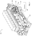
FIG. 1 , there is shown a perspective view of a portion of apower system 100 for providing power to a variety of machines, including on-highway trucks, construction vehicles, marine vessels, stationary generators, automobiles, agricultural vehicles, and recreational vehicles. Theengine 102 may be an internal combustion engine, such as a gasoline engine, a diesel engine, or any other exhaust gas producing engine. And further, theengine 102 may be of any size, have any number cylinders, and have any configuration. - Also, in
FIG. 1 , there is shown asystem 104 for determining information related to a rotation of ashaft 106, such as an angular position or velocity thereof. Theshaft 106 is shown as camshaft, but thesystem 104 could be used with a crankshaft or a transmission shaft or any other kind of rotating shaft. - The
controller 116 may receive real time signal inputs from thesensor 114, and it may be in the form of an engine control unit or a transmission control unit or part of a controller area network, to name just a few examples. Thecontroller 116 may use the angular position and velocity for many reasons, including for determining when to command fuel into the cylinders of theengine 102. - The
wheel 108 includes a plurality oftargets 110 andgaps 112 positioned therebetween, and they may be positioned about a circumference of thewheel 108. The other circumferential spaces may be, for example, the result of a rise and fall between twoconsecutive targets 110 positioned right beside one another. Thewheel 108 may be made of steel or stainless steel or any other rigid material, and it may be mounted to theshaft 106, using a press fit or a weld, for example. The signal, provided by thesensor 114, may vary in amplitude as thetargets 110 andgaps 112 pass thereby. Various sensors could be used as thesensor 114, including variable reluctance sensors, Hall effect sensors, optical sensors, and proximity sensors. An axis defined by thesensor 114 is shown being in parallel with an axis defined by thewheel 108, though in other arrangements, the axes could be perpendicular or of any other orientation. - Referring to
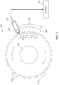
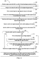
FIG. 2 , there is shown a schematic illustration of thesystem 104, and referring toFIG. 3 , there is shown amethod 200 for determining information related to the rotation of theshaft 106. Atstep 202, thecontroller 116 receives a signal associated with thetargets 110 andgaps 112 passing by thesensor 114. - As shown in the
illustrated wheel 108, thetargets 110 may be in immediate and consecutive sequence with both sides of all of the gaps 112 (i.e., thewheel 108 may not have twogaps 112 in consecutive sequence with one another). By arranging thegaps 112 in this way, thewheel 108 may provide a more consistent, stable signal to thecontroller 116. Alternatively, with double and triple gaps, accelerations of thewheel 108 may be more difficult to detect, and there may be misidentifications (e.g., a double gap may result in a signal that is relatively similar to a triple gap). Additionally, by not havinggaps 112 in consecutive sequence, the target-and-gap sequences may be angularly shorter, all other things equal. - In some embodiments of the
wheel 108, all of thetargets 110 may be identical to one another, meaning that they may all have identical widths and/or heights. Havingidentical targets 110 may result in the signal that thecontroller 116 receives being easier to delineate intoindividual targets 110. - At
step 204, thecontroller 116 may assign a target time stamp to eachtarget 110 in the target-and-gap sequence. Thecontroller 116 may estimate when thegaps 112 pass by thesensor 114 based on the target time stamps. For example, a relatively long amount of time between consecutive target time stamps may be the result of agap 112 between the previously sensedtargets 110. - At
step 206, thecontroller 116 forms a sensed target-and-gap sequence based on the signal, an example of which is illustrated by thereference numeral 118. Theexample sequence 118 is just one of the many different possible sensed target-and-gap sequences on just one example of a wheel. For example, other sensed target-and-gap sequences could be offset from theexample sequence 118 and/or of a different length and the like. Theexample sequence 118 represents a subset of thetargets 110 andgaps 112, shown asreference numerals 1 through 10 inFIG. 2 . - The
controller 116 may use a binary number system to represent the sensed target-and-gap sequence. In the illustrated embodiment and starting position, theexample sequence 118 forms the binary array of [1111110110] if theshaft 106 begins rotating clockwise at 1 and rotates to 2, 3, 4, and so on. In this example, thecontroller 116 may be able to determine the angular position and velocity of thewheel 108 upon seeing a sum of tentargets 110 and/orgaps 112. This means that thecontroller 116 may determine this information after thewheel 108 rotates by (10/72)*360°. The length of the binary array (and the underlying sensed target-and-gap sequence) may vary, depending on the design of thewheel 108 and what is saved in memory on thecontroller 116. Thecontroller 116 may also use a ternary system or a quaternion system and so on, depending on the sizes and widths of thetargets 110 andgaps 112, for example. - At
step 208, thecontroller 116 compares the sensed sequence to a set of known target-and-gap sequences stored in memory, each known sequence being associated with a respective, known circumferential portion of thewheel 108. The known sequences may be stored in memory in thecontroller 116, based on the arrangement of thetargets 110 andgaps 112 positioned about thewheel 108. Referring back to theexample sequence 118, [1111110110], thecontroller 116 may have this same array stored into memory as a known sequence, and it may associate that sequence with a known circumferential portion of thewheel 108, an example of which is shown byreference numeral 122. In some examples ofsystem 104, such information may be stored for every incremental position about thewheel 108. - Exemplarily, a total number of known sequences may be equivalent to a total sum of the
targets 110 andgaps 112. For example, the illustratedwheel 108 has a sum of 72different targets 110 andgaps 112, and with such awheel 108, thecontroller 116 may store a sum of 72 known sequences, each of which may be unique. The known sequences may be overlapping, such that two that are directly adjacent to one another are overlapping at all bits, but for one. - There are various methods for designing
wheel 108 or one similar, but one example method for designing it and placing thetargets 110 andgaps 112 is by writing a program that incrementally assigns them. For example, the method may incrementally work around thewheel 108, so as to always place atarget 110 or agap 112, such that thenext target 110 orgap 112 results in a unique subset array. In other words, each array may be an array of numbers and each may be unique relative to all other arrays. Such a method may assume that all of thetargets 110 andgaps 112 have equal widths, and that both sides allgaps 112 are surrounded byconsecutive targets 110. These unique arrays may be saved as the known sequences, and they may all be unique and representative of a circumferential portion of thewheel 108. - In some embodiments of the
wheel 108, each known sequence may be unique relative to all of the others, even when a length of each known sequence is a mathematically minimum length for doing so (for a sum of thetargets 110 and gaps 112). For example, in the illustratedsystem 104, the length of the known sequence is ten units long, and each such sequence is unique. This is a mathematical minimum for the illustratedwheel 108, having a sum of seventy-twotargets 110 andgaps 112. - There are various methods for determining the mathematical minimum. For example, calculating this minimum may be based on assuming that the
targets 110 andgaps 112 have the same widths, that they represent numbers, and that eachgap 112 is surrounded byconsecutive targets 110. And further, calculating this minimum may based on trying a large sequence length and then incrementing down in sequence length until the length results in overlapping, but repeating, known sequences, regardless of how they are arranged in sequence. Then, calculating this minimum may finally be found by incrementing up in sequence length by one additional bit. - At
step 210, thecontroller 116 determines which respective known sequence is identical to the sensed target-and-gap sequence. Again, referring to theexample sequence 118, which in this embodiment and starting point is [1111110110], thecontroller 116 may determine which respective known sequence is identical thereto. The known sequence may be specific to a given circumferential portion of thewheel 108 and stored into memory, such that thecontroller 116 may then know the position of thewheel 108. In some embodiments of themethod 200, if the sensed target-and-gap sequence matches a known sequence atstep 210, then themethod 200 may transition directly tosteps method 200 may transition to a step similar to step 218, as discussed below. - In the illustrated embodiment of the
method 200, atstep 212, thecontroller 116 receives a verification signal associated with a verifier passing by thesensor 114. The verifier may indicate either atarget 110 or agap 112 of the plurality oftargets 110 andgaps 112 passing by thesensor 114. As illustrated, theexample verifier 120 is represented by thereference numeral 11, and it represents one of thetargets 110. - At
step 214, thecontroller 116 may add the verifier to an end of the sensed target-and-gap sequence based on the verification signal. For example, theexample sequence 118 of [1111110110] may be offset and become [1111101101], so as to include theexample verifier 120. Or in some other embodiments, the sensed target and gap may be added to, resulting in a longer sequence that also includes the verifier. - At
step 216, thecontroller 116 may compare the verifier to an expected verifier. The expected verifier may be stored in memory and be expected to follow the sensed target-and-gap sequence. Atstep 218, thecontroller 116 may form a new, sensed target-and-gap sequence if the verifier does not match the expected verifier. In other words, a non-matching verifier may indicate that there is an error in the signal from thesensor 114, or an error in processing the signal in thecontroller 116. As such, thecontroller 116 may form the new, sensed target-and-gap sequence and try again. - At
step 220, thecontroller 116 may compare the new, sensed target-and-gap sequence to the set of known sequences. And atstep 222, thecontroller 116 may determine whether a known sequence is identical to the new, sensed target-and-gap sequence. If there is a match atstep 222, then thecontroller 116 may proceed to step 224. But alternatively, if there is not a match, then thecontroller 116 may return to step 218 and form yet another new, sensed target-and-gap sequence. Such difficulties may be an indication of issues related to thesensor 114, the signal, or the controller 116-some or all of which may be based on the angular velocity (e.g., too slow) or accelerations (e.g., too fast and random) of theshaft 106. - At
step 224, thecontroller 116 may determine an angular velocity of theshaft 106 based on the target time stamps. For example, thecontroller 116 may determine the angular velocity by dividing the angular distance between thetargets 110 andgaps 112 by the measured time differences between the target time stamps. Atstep 226, thecontroller 116 may determine an angular position of theshaft 106 at a given time based on the target time stamps and the determination of which known sequence is identical to the sensed target-and-gap sequence. Exemplarily, thecontroller 116 may use the angular velocity and position information for determining when to output signals related to when to inject and ignite fuel in the respective cylinders, when to open and close intake valves, when to open and close output valves, and the like. Or more simply, thecontroller 116 may output signals related to when to inject and ignite fuel in the respective cylinders, when to open and close intake valves, when to open and close output valves, and the like based on the determination of which respective known target-and-gap sequence is identical to the sensed target-and-gap sequence. - While the disclosure has been illustrated and described in detail in the drawings and foregoing description, such illustration and description is to be considered as exemplary and not restrictive in character, it being understood that illustrative embodiments have been shown and described and that all changes and modifications that come within the spirit of the disclosure are desired to be protected. It will be noted that alternative embodiments of the present disclosure may not include all of the features described yet still benefit from at least some of the advantages of such features. Those of ordinary skill in the art may readily devise their own implementations that incorporate one or more of the features of the present disclosure and fall within the spirit and scope of the present invention as defined by the appended claims.
Claims (15)
- A method for determining information related to a rotation of a shaft, the method comprising:receiving a signal associated with a plurality of targets and gaps passing by a sensor, the targets and gaps being positioned around a circumference of a wheel that is fixed for rotation with the shaft, the gaps being positioned between the targets;forming a sensed target-and-gap sequence based on the signal, the sensed target-and-gap sequence representing a subset of the targets and gaps;comparing the sensed target-and-gap sequence to a set of known target-and-gap sequences stored in memory, each known target-and-gap sequence being associated with a respective, known circumferential portion of the wheel; anddetermining which respective known target-and-gap sequence is identical to the sensed target-and-gap sequence.
- The method of claim 1, wherein the forming comprises forming the sensed target-and-gap sequence out of numbers.
- The method of claim 1, comprising:receiving a verification signal associated with a verifier passing by the sensor, the verifier indicating either a target or a gap of the target and gaps;adding the verifier to an end of the sensed target-and-gap sequence based on the verification signal; andcomparing the verifier to an expected verifier, the expected verifier being stored in memory and expected to follow the sensed target-and-gap sequence.
- The method of claim 3, comprising:forming a new, sensed target-and-gap sequence if the verifier does not match the expected verifier;comparing the new, sensed target-and-gap sequence to the set of known target-and-gap sequences; anddetermining which known target-and-gap sequence is identical to the new, sensed target-and-gap sequence.
- The method of claim 4, comprising confirming an angular position of the shaft based which known target-and-gap sequence is identical to the new, sensed target-and-gap sequence.
- The method of claim 1, comprising assigning a target time stamp to each target in the target-and-gap sequence, each target time stamp representing when each respective target is sensed.
- The method of claim 6, comprising determining an angular velocity of the shaft, at a given time, based on the target time stamps.
- The method of claim 6, comprising determining an angular position of the shaft, at a given time, based on:the target time stamps; andthe determination of which known target-and-gap sequence is identical to the sensed target-and-gap sequence.
- A system for determining information related to a rotation of a shaft, the system comprising:a wheel fixed for rotation with the shaft, the wheel comprising a plurality of targets and a plurality of gaps positioned sporadically therebetween, the targets and gaps being positioned about a circumference of the wheel;a sensor positioned adjacent to the wheel; anda controller coupled to the sensor, the controller configured to:receive a signal from the sensor, the signal being associated with the plurality of targets and gaps passing by the sensor;form a sensed target-and-gap sequence as each target-and-gap is sensed, the sensed target-and-gap sequence being a subset of the targets and the gaps;compare the sensed target-and-gap sequence to a set of known target-and-gap sequences stored in memory, each known target-and-gap sequence being associated with a known circumferential portion of the wheel; anddetermine which respective known target-and-gap sequence is identical to the sensed target-and-gap sequence.
- The system of claim 9, wherein the targets of the target-and-gap sequence are in immediate and consecutive sequence with both sides of all of the gaps of the target-and-gap sequence.
- The system of claim 9, wherein all of the targets are identical to one another.
- The system of claim 9, wherein all of the targets and all of the gaps have identical widths.
- The system of claim 9, wherein a total number of known target-and-gap sequences is equivalent to a total sum of the targets and gaps.
- The system of claim 9, wherein each known target-and-gap sequence is a unique sequence, and a length of each known target-and-gap sequence is a mathematically minimum length for a sum of the targets and gaps.
- The system of claim 9, wherein the controller is configured to:receive a verification signal from the sensor, the verification signal is associated with a verifier that is immediately following the sensed target-and-gap sequence and that indicates either a verifying target or a verifying gap;add the verifier to an end of the sensed target-and-gap sequence based on the verification signal; andcompare the verifier to an expected verifier, the expected verifier is based on a known verifier that is stored in memory and that is expected to follow the sensed target-and-gap sequence;form a new, sensed target-and-gap sequence if the verifier does not match the expected verifier;compare the new, sensed target-and-gap sequence to the set of known target-and-gap sequences stored in memory;determine which respective known target-and-gap sequence is identical to the new, sensed target-and-gap sequence; andconfirm information related to the rotation of the shaft if the verifier matches the expected verifier.
Applications Claiming Priority (1)
| Application Number | Priority Date | Filing Date | Title |
|---|---|---|---|
| US14/722,206 US9765711B2 (en) | 2015-05-27 | 2015-05-27 | System and method for determining information related to a rotation of a shaft |
Publications (1)
| Publication Number | Publication Date |
|---|---|
| EP3115751A1 true EP3115751A1 (en) | 2017-01-11 |
Family
ID=55968962
Family Applications (1)
| Application Number | Title | Priority Date | Filing Date |
|---|---|---|---|
| EP16169143.1A Withdrawn EP3115751A1 (en) | 2015-05-27 | 2016-05-11 | A system and method for determining information related to a rotation of a shaft |
Country Status (2)
| Country | Link |
|---|---|
| US (1) | US9765711B2 (en) |
| EP (1) | EP3115751A1 (en) |
Families Citing this family (8)
| Publication number | Priority date | Publication date | Assignee | Title |
|---|---|---|---|---|
| DE102015225556A1 (en) * | 2015-12-17 | 2017-06-22 | Robert Bosch Gmbh | Camshaft generator gear |
| DE102019210849A1 (en) * | 2018-07-30 | 2020-01-30 | Bosch Limited | A ENGINE CONTROL UNIT (ECU) AND METHOD FOR ADAPTING THE ECU TO PULSE WHEEL IRREGULARITIES |
| US11131567B2 (en) | 2019-02-08 | 2021-09-28 | Honda Motor Co., Ltd. | Systems and methods for error detection in crankshaft tooth encoding |
| US11181016B2 (en) | 2019-02-08 | 2021-11-23 | Honda Motor Co., Ltd. | Systems and methods for a crank sensor having multiple sensors and a magnetic element |
| US11162444B2 (en) | 2019-02-08 | 2021-11-02 | Honda Motor Co., Ltd. | Systems and methods for a crank sensor having multiple sensors and a magnetic element |
| US11199426B2 (en) | 2019-02-08 | 2021-12-14 | Honda Motor Co., Ltd. | Systems and methods for crankshaft tooth encoding |
| US11639859B2 (en) * | 2020-05-22 | 2023-05-02 | Deere & Company | Method for determining rotational position of a rotating camshaft on a reciprocating engine using a target with a pattern of teeth and a collection of detection algorithms |
| US11959820B2 (en) | 2021-03-17 | 2024-04-16 | Honda Motor Co., Ltd. | Pulser plate balancing |
Citations (3)
| Publication number | Priority date | Publication date | Assignee | Title |
|---|---|---|---|---|
| DE3623449A1 (en) * | 1986-07-11 | 1988-01-14 | Siemens Ag | Arrangement for obtaining angle signals |
| EP0947805A2 (en) * | 1998-04-02 | 1999-10-06 | J.C. Bamford Excavators Limited | An apparatus for determining the position of a movable mechanical element and method of marking a mechanical element |
| US20030231013A1 (en) * | 2002-06-11 | 2003-12-18 | Honeywell International, Inc., Law Dept. Ab2 | Speed sensing system with automatic sensitivity adjustment |
Family Cites Families (14)
| Publication number | Priority date | Publication date | Assignee | Title |
|---|---|---|---|---|
| US5184590A (en) * | 1991-02-12 | 1993-02-09 | Mitsubishi Denki Kabushiki Kaisha | Engine timing control apparatus |
| US5250925A (en) * | 1992-05-11 | 1993-10-05 | General Motors Corporation | Package for speed sensing device having minimum air gap |
| US5361629A (en) * | 1992-08-21 | 1994-11-08 | Chrysler Corporation | Single sensor misfire detection apparatus and method for an internal combustion engine |
| AU6522896A (en) * | 1995-08-02 | 1997-03-05 | Durakool Incorporated | Gear tooth sensor with improved resolution and stability |
| JP3186545B2 (en) * | 1995-10-06 | 2001-07-11 | 三菱電機株式会社 | 4-cycle internal combustion engine controller |
| US5794171A (en) * | 1996-02-29 | 1998-08-11 | Ford Global Technologies, Inc. | Process for deriving predictive model of crankshaft rotation of a combustion engine |
| US6604411B1 (en) * | 1999-09-10 | 2003-08-12 | Ford Global Technologies, Llc | Engine starting method |
| JP4555510B2 (en) * | 2001-06-21 | 2010-10-06 | アイシン精機株式会社 | Rotation detection sensor |
| US6752009B2 (en) * | 2001-08-03 | 2004-06-22 | General Motors Corporation | Encoded crank position sensor |
| CN1961319A (en) * | 2004-03-29 | 2007-05-09 | 西南研究会 | Engine crankshaft position recognition and tracking method applicable to cam and crankshaft signals with arbitrary patterns |
| US7142973B2 (en) * | 2004-06-11 | 2006-11-28 | Denso Corporation | Engine control apparatus designed to ensure accuracy in determining engine position |
| US7362018B1 (en) * | 2006-01-23 | 2008-04-22 | Brunswick Corporation | Encoder alternator |
| US9845752B2 (en) | 2010-09-29 | 2017-12-19 | GM Global Technology Operations LLC | Systems and methods for determining crankshaft position based indicated mean effective pressure (IMEP) |
| JP6071568B2 (en) * | 2013-01-16 | 2017-02-01 | 本田技研工業株式会社 | Vehicle control device |
-
2015
- 2015-05-27 US US14/722,206 patent/US9765711B2/en active Active
-
2016
- 2016-05-11 EP EP16169143.1A patent/EP3115751A1/en not_active Withdrawn
Patent Citations (3)
| Publication number | Priority date | Publication date | Assignee | Title |
|---|---|---|---|---|
| DE3623449A1 (en) * | 1986-07-11 | 1988-01-14 | Siemens Ag | Arrangement for obtaining angle signals |
| EP0947805A2 (en) * | 1998-04-02 | 1999-10-06 | J.C. Bamford Excavators Limited | An apparatus for determining the position of a movable mechanical element and method of marking a mechanical element |
| US20030231013A1 (en) * | 2002-06-11 | 2003-12-18 | Honeywell International, Inc., Law Dept. Ab2 | Speed sensing system with automatic sensitivity adjustment |
Also Published As
| Publication number | Publication date |
|---|---|
| US9765711B2 (en) | 2017-09-19 |
| US20160348597A1 (en) | 2016-12-01 |
Similar Documents
| Publication | Publication Date | Title |
|---|---|---|
| US9765711B2 (en) | System and method for determining information related to a rotation of a shaft | |
| DE102017105239B4 (en) | Control unit and control method for an internal combustion engine | |
| US6546912B2 (en) | On-line individual fuel injector diagnostics from instantaneous engine speed measurements | |
| US8046155B2 (en) | Method and apparatus for misfire detection using engine cycles at least subsequent to actual misfire event | |
| EP0754326B1 (en) | Adaptive profile correction for rotating position encoders in reciprocating engines | |
| JP4484772B2 (en) | Misfire detection device for internal combustion engine | |
| JP2016070255A (en) | Accident fire determination device | |
| US20140360254A1 (en) | Camshaft position pulse-generating wheel and method and device for ascertaining a camshaft position | |
| JP3997878B2 (en) | Misfire detection device | |
| JP3786269B2 (en) | Crank angle detection device for internal combustion engine | |
| US7540185B2 (en) | System and method for detecting engine misfires | |
| JP4834638B2 (en) | Engine cylinder determination device | |
| US5767394A (en) | Method and system for early cylinder identification | |
| EP1367378A3 (en) | Apparatus and method for detecting misfire in internal combustion engine | |
| CN1619278B (en) | Method for finding the angular acceleration of a drive shaft of an internal combustion engine by means of a gear wheel integral with said drive shaft | |
| JP2855969B2 (en) | Misfire detection device for internal combustion engine | |
| KR102153484B1 (en) | Misfire diagnosis method and device of Multi cylinder four-stroke engine | |
| US11639859B2 (en) | Method for determining rotational position of a rotating camshaft on a reciprocating engine using a target with a pattern of teeth and a collection of detection algorithms | |
| JP4316914B2 (en) | Misfire detection device | |
| KR102202723B1 (en) | Misfire diagnosis method and device of Multi cylinder four-stroke engine | |
| CN110139978B (en) | Cylinder detection in a four-stroke internal combustion engine | |
| JP2003166821A (en) | Angle measuring apparatus or rotational frequency measuring apparatus | |
| JP4207579B2 (en) | Misfire detection device for multi-cylinder internal combustion engine | |
| KR102264304B1 (en) | Misfire diagnosis method and device of Multi cylinder four-stroke engine | |
| US6816775B2 (en) | Method for detecting misfiring in a multi-cylinder internal combustion engine |
Legal Events
| Date | Code | Title | Description |
|---|---|---|---|
| PUAI | Public reference made under article 153(3) epc to a published international application that has entered the european phase |
Free format text: ORIGINAL CODE: 0009012 |
|
| AK | Designated contracting states |
Kind code of ref document: A1 Designated state(s): AL AT BE BG CH CY CZ DE DK EE ES FI FR GB GR HR HU IE IS IT LI LT LU LV MC MK MT NL NO PL PT RO RS SE SI SK SM TR |
|
| AX | Request for extension of the european patent |
Extension state: BA ME |
|
| 17P | Request for examination filed |
Effective date: 20170711 |
|
| RBV | Designated contracting states (corrected) |
Designated state(s): AL AT BE BG CH CY CZ DE DK EE ES FI FR GB GR HR HU IE IS IT LI LT LU LV MC MK MT NL NO PL PT RO RS SE SI SK SM TR |
|
| 17Q | First examination report despatched |
Effective date: 20171208 |
|
| STAA | Information on the status of an ep patent application or granted ep patent |
Free format text: STATUS: THE APPLICATION IS DEEMED TO BE WITHDRAWN |
|
| 18D | Application deemed to be withdrawn |
Effective date: 20180419 |