EP3115659B1 - Kontaktlose dichtungsanordnung für eine drehausrüstung mit verbindung zwischen benachbarten rotoren - Google Patents
Kontaktlose dichtungsanordnung für eine drehausrüstung mit verbindung zwischen benachbarten rotoren Download PDFInfo
- Publication number
- EP3115659B1 EP3115659B1 EP16178693.4A EP16178693A EP3115659B1 EP 3115659 B1 EP3115659 B1 EP 3115659B1 EP 16178693 A EP16178693 A EP 16178693A EP 3115659 B1 EP3115659 B1 EP 3115659B1
- Authority
- EP
- European Patent Office
- Prior art keywords
- linkage
- assembly
- rotor
- seal
- stator
- Prior art date
- Legal status (The legal status is an assumption and is not a legal conclusion. Google has not performed a legal analysis and makes no representation as to the accuracy of the status listed.)
- Active
Links
Images


Classifications
-
- F—MECHANICAL ENGINEERING; LIGHTING; HEATING; WEAPONS; BLASTING
- F01—MACHINES OR ENGINES IN GENERAL; ENGINE PLANTS IN GENERAL; STEAM ENGINES
- F01D—NON-POSITIVE DISPLACEMENT MACHINES OR ENGINES, e.g. STEAM TURBINES
- F01D11/00—Preventing or minimising internal leakage of working-fluid, e.g. between stages
- F01D11/08—Preventing or minimising internal leakage of working-fluid, e.g. between stages for sealing space between rotor blade tips and stator
-
- B—PERFORMING OPERATIONS; TRANSPORTING
- B64—AIRCRAFT; AVIATION; COSMONAUTICS
- B64D—EQUIPMENT FOR FITTING IN OR TO AIRCRAFT; FLIGHT SUITS; PARACHUTES; ARRANGEMENT OR MOUNTING OF POWER PLANTS OR PROPULSION TRANSMISSIONS IN AIRCRAFT
- B64D27/00—Arrangement or mounting of power plants in aircraft; Aircraft characterised by the type or position of power plants
- B64D27/02—Aircraft characterised by the type or position of power plants
- B64D27/10—Aircraft characterised by the type or position of power plants of gas-turbine type
-
- F—MECHANICAL ENGINEERING; LIGHTING; HEATING; WEAPONS; BLASTING
- F01—MACHINES OR ENGINES IN GENERAL; ENGINE PLANTS IN GENERAL; STEAM ENGINES
- F01D—NON-POSITIVE DISPLACEMENT MACHINES OR ENGINES, e.g. STEAM TURBINES
- F01D11/00—Preventing or minimising internal leakage of working-fluid, e.g. between stages
- F01D11/001—Preventing or minimising internal leakage of working-fluid, e.g. between stages for sealing space between stator blade and rotor
-
- F—MECHANICAL ENGINEERING; LIGHTING; HEATING; WEAPONS; BLASTING
- F01—MACHINES OR ENGINES IN GENERAL; ENGINE PLANTS IN GENERAL; STEAM ENGINES
- F01D—NON-POSITIVE DISPLACEMENT MACHINES OR ENGINES, e.g. STEAM TURBINES
- F01D11/00—Preventing or minimising internal leakage of working-fluid, e.g. between stages
- F01D11/003—Preventing or minimising internal leakage of working-fluid, e.g. between stages by packing rings; Mechanical seals
-
- F—MECHANICAL ENGINEERING; LIGHTING; HEATING; WEAPONS; BLASTING
- F01—MACHINES OR ENGINES IN GENERAL; ENGINE PLANTS IN GENERAL; STEAM ENGINES
- F01D—NON-POSITIVE DISPLACEMENT MACHINES OR ENGINES, e.g. STEAM TURBINES
- F01D11/00—Preventing or minimising internal leakage of working-fluid, e.g. between stages
- F01D11/02—Preventing or minimising internal leakage of working-fluid, e.g. between stages by non-contact sealings, e.g. of labyrinth type
- F01D11/04—Preventing or minimising internal leakage of working-fluid, e.g. between stages by non-contact sealings, e.g. of labyrinth type using sealing fluid, e.g. steam
-
- F—MECHANICAL ENGINEERING; LIGHTING; HEATING; WEAPONS; BLASTING
- F04—POSITIVE - DISPLACEMENT MACHINES FOR LIQUIDS; PUMPS FOR LIQUIDS OR ELASTIC FLUIDS
- F04D—NON-POSITIVE-DISPLACEMENT PUMPS
- F04D29/00—Details, component parts, or accessories
- F04D29/26—Rotors specially for elastic fluids
- F04D29/32—Rotors specially for elastic fluids for axial flow pumps
- F04D29/321—Rotors specially for elastic fluids for axial flow pumps for axial flow compressors
- F04D29/324—Blades
-
- F—MECHANICAL ENGINEERING; LIGHTING; HEATING; WEAPONS; BLASTING
- F04—POSITIVE - DISPLACEMENT MACHINES FOR LIQUIDS; PUMPS FOR LIQUIDS OR ELASTIC FLUIDS
- F04D—NON-POSITIVE-DISPLACEMENT PUMPS
- F04D29/00—Details, component parts, or accessories
- F04D29/40—Casings; Connections of working fluid
- F04D29/52—Casings; Connections of working fluid for axial pumps
- F04D29/54—Fluid-guiding means, e.g. diffusers
- F04D29/541—Specially adapted for elastic fluid pumps
- F04D29/545—Ducts
-
- F—MECHANICAL ENGINEERING; LIGHTING; HEATING; WEAPONS; BLASTING
- F16—ENGINEERING ELEMENTS AND UNITS; GENERAL MEASURES FOR PRODUCING AND MAINTAINING EFFECTIVE FUNCTIONING OF MACHINES OR INSTALLATIONS; THERMAL INSULATION IN GENERAL
- F16J—PISTONS; CYLINDERS; SEALINGS
- F16J15/00—Sealings
- F16J15/16—Sealings between relatively-moving surfaces
- F16J15/32—Sealings between relatively-moving surfaces with elastic sealings, e.g. O-rings
- F16J15/3284—Sealings between relatively-moving surfaces with elastic sealings, e.g. O-rings characterised by their structure; Selection of materials
-
- F—MECHANICAL ENGINEERING; LIGHTING; HEATING; WEAPONS; BLASTING
- F16—ENGINEERING ELEMENTS AND UNITS; GENERAL MEASURES FOR PRODUCING AND MAINTAINING EFFECTIVE FUNCTIONING OF MACHINES OR INSTALLATIONS; THERMAL INSULATION IN GENERAL
- F16J—PISTONS; CYLINDERS; SEALINGS
- F16J15/00—Sealings
- F16J15/44—Free-space packings
- F16J15/441—Free-space packings with floating ring
- F16J15/442—Free-space packings with floating ring segmented
-
- F—MECHANICAL ENGINEERING; LIGHTING; HEATING; WEAPONS; BLASTING
- F05—INDEXING SCHEMES RELATING TO ENGINES OR PUMPS IN VARIOUS SUBCLASSES OF CLASSES F01-F04
- F05D—INDEXING SCHEME FOR ASPECTS RELATING TO NON-POSITIVE-DISPLACEMENT MACHINES OR ENGINES, GAS-TURBINES OR JET-PROPULSION PLANTS
- F05D2220/00—Application
- F05D2220/30—Application in turbines
- F05D2220/32—Application in turbines in gas turbines
-
- F—MECHANICAL ENGINEERING; LIGHTING; HEATING; WEAPONS; BLASTING
- F05—INDEXING SCHEMES RELATING TO ENGINES OR PUMPS IN VARIOUS SUBCLASSES OF CLASSES F01-F04
- F05D—INDEXING SCHEME FOR ASPECTS RELATING TO NON-POSITIVE-DISPLACEMENT MACHINES OR ENGINES, GAS-TURBINES OR JET-PROPULSION PLANTS
- F05D2240/00—Components
- F05D2240/55—Seals
Definitions
- This disclosure relates generally to rotational equipment and, more particularly, to a non-contact seal assembly for rotational equipment.
- Rotational equipment typically includes one or more seal assemblies for sealing gaps between rotors and stators.
- a typical seal assembly includes a contact seal with a seal element such as a knife edge seal that engages a seal land.
- a contact seal can generate a significant quantity of heat which can reduce efficiency of the rotational equipment as well as subject other components of the rotational equipment to high temperatures.
- other components of the rotational equipment may be constructed from specialty high temperature materials, which can significantly increase the manufacturing and servicing costs of the rotational equipment.
- non-contact seals have been developed in an effort to reduce heat within rotational equipment, such non-contact seals can be difficult to configure within the rotational equipment.
- Such non-contact seals and associated components may also need to be replaced when incidental contact occurs.
- WO 2014/143284 A1 discloses features of the preamble of claim 1, and EP 1420145 A2 (which discloses an assembly according to the preamble of appended claim 1) and FR 2926612 A1 disclose other assemblies for rotational equipment.
- an assembly is provided as claimed in claim 1.
- the base may be configured with a monolithic full hoop body.
- a carrier may be included that connects the non-contact seal to the stator.
- the carrier may be configured with a monolithic full hoop body.
- the seal portion of the linkage is radially thicker than adjacent portions of the linkage.
- the stator may be configured with a monolithic full hoop body.
- the stator may be configured as or include a fairing configured to form an axial portion of an inner peripheral boundary of a core gas path through the rotational equipment.
- the rotational equipment may be configured as a gas turbine engine.
- a plurality of first rotor blades may be included and arranged around and connected to the first rotor disk.
- a plurality of second rotor blades may be included and arranged around and connected to the second rotor disk.
- a plurality of stator vanes may be included and arranged around and connected to the stator. The stator vanes may be axially between the first rotor blades and the second rotor blades.
- the linkage may include a flange connector attached to the second rotor disk with one or more fasteners.
- the flange connector may have an outermost radius.
- the non-contact seal may have an innermost radius that is greater than the outermost radius.
- the linkage may have an outermost radius and the non-contact seal has an innermost radius that is greater than the outermost radius.
- a portion of the linkage may be configured to pass through the non-contact seal during assembly.
- the linkage may be configured to partially pass axially through the non-contact seal during assembly.
- a carrier may be included which mounts the base to the fairing.
- the carrier may be configured with a monolithic full hoop body.
- the fairing may be configured with a monolithic full hoop body.
- the base may be configured with a monolithic full hoop body.
- a portion of the linkage which forms the cylindrical surface is radially thicker than axially adjacent portions of the linkage.
- the portion of the linkage has a hardface which forms the cylindrical surface.
- the seal portion of the linkage is radially thicker by an additional thickness than adjacent portions of the linkage.
- the hardface provides a portion of the additional thickness and forms the cylindrical surface.
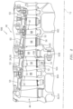
- FIG. 1 is a side cutaway illustration of a gas turbine engine 10 for an aircraft propulsion system.
- This turbine engine 10 is configured as a geared turbofan engine, and extends along an axial centerline 12 between an upstream airflow inlet 14 and a downstream airflow exhaust 16.
- the turbine engine 10 includes a fan section 18, a compressor section 19, a combustor section 20 and a turbine section 21.
- the compressor section 19 includes a low pressure compressor (LPC) section 19A and a high pressure compressor (HPC) section 19B.
- the turbine section 21 includes a high pressure turbine (HPT) section 21A and a low pressure turbine (LPT) section 21B.
- the engine sections 18-21 are arranged sequentially along the centerline 12 within an engine housing 22.
- This housing 22 includes an inner case 24 (e.g., a core case) and an outer case 26 (e.g., a fan case).
- the inner case 24 may house one or more of the engine sections 19-21 (e.g., an engine core), and may be housed within an inner nacelle / inner fixed structure (not shown) which provides an aerodynamic cover for the inner case 24.
- the inner case 24 may be configured with one or more axial and/or circumferential inner sub-casings; e.g., case segments.
- the outer case 26 may house at least the fan section 18, and may be housed within an outer nacelle (not shown) which provides an aerodynamic cover for the outer case 26. Briefly, the outer nacelle along with the outer case 26 overlaps the inner nacelle thereby defining a bypass gas path 28 radially between the nacelles.
- the outer case 26 may be configured with one or more axial and/or circum
- Each of the engine sections 18-19B, 21A and 21B includes a respective rotor 30-34.
- Each of these rotors 30-34 includes a plurality of rotor blades arranged circumferentially around and connected to one or more respective rotor disks.
- the rotor blades may be formed integral with or mechanically fastened, welded, brazed, adhered and/or otherwise attached to the respective rotor disk(s).
- Each of the rotors 31-34 may also include one or more rotor disk linkages, which interconnect adjacent rotor disks within the respective rotor.
- the fan rotor 30 is connected to a gear train 36, for example, through a fan shaft 38.
- the gear train 36 and the LPC rotor 31 are connected to and driven by the LPT rotor 34 through a low speed shaft 39.
- the HPC rotor 32 is connected to and driven by the HPT rotor 33 through a high speed shaft 40.
- the shafts 38-40 are rotatably supported by a plurality of bearings 42; e.g., rolling element and/or thrust bearings. Each of these bearings 42 is connected to the engine housing 22 (e.g., the inner case 24) by at least one stationary structure such as, for example, an annular support strut.
- the core gas path 44 extends sequentially through the engine sections 19-21.
- the air within the core gas path 44 may be referred to as "core air”.
- the air within the bypass gas path 28 may be referred to as "bypass air”.
- the core air is compressed by the compressor rotors 31 and 32 and directed into a combustion chamber 46 of a combustor in the combustor section 20.
- Fuel is injected into the combustion chamber 46 and mixed with the compressed core air to provide a fuel-air mixture.
- This fuel air mixture is ignited and combustion products thereof flow through and sequentially cause the turbine rotors 33 and 34 to rotate.
- the rotation of the turbine rotors 33 and 34 respectively drive rotation of the compressor rotors 32 and 31 and, thus, compression of the air received from a core airflow inlet.
- the rotation of the turbine rotor 34 also drives rotation of the fan rotor 30, which propels bypass air through and out of the bypass gas path 28.
- the propulsion of the bypass air may account for a majority of thrust generated by the turbine engine 10, e.g., more than seventy-five percent (75%) of engine thrust.
- the turbine engine 10 of the present disclosure is not limited to the foregoing exemplary thrust ratio.
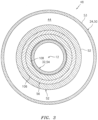
- FIG. 2 illustrates an assembly 48 for the turbine engine 10.
- This turbine engine assembly 48 includes an assemblage of stator elements 50-52, a rotor 54 and one or more non-contact seal assemblies 56.
- the turbine engine case 50 may be configured having one or more monolithic full hoop bodies 53.
- the term "monolithic” may describe a component which is formed as a single unitary body.
- the turbine engine case 50 includes a plurality of integral, tubular bodies 53, where each body 53 is formed without any mechanically interconnected axial and/or circumferential segments.
- a monolithic body may include one or more bodies bonded together.
- a metal band may be formed into a hoop and its opposing ends may be welded and/or otherwise bonded together.
- arcuate segments e.g., halves
- the assembly 48 of the present disclosure is not limited to the foregoing exemplary turbine engine case configuration.
- the turbine engine case 50 may be configured with a single full hoop body or as a circumferentially segmented body.
- each array 51 of stator vanes 58 includes a plurality of stator vanes 58. These stator vanes 58 are arranged circumferentially around the centerline 12 and radially between the rotor 54 and the turbine engine case 50. Each of the stator vanes 58 extends radially from a respective one of the stators 52 to the turbine engine case 50.
- stator vanes 58 of FIG. 2 is configured as a fixed stator vane.
- fixed stator vane may describe a stator vane which is fixedly attached to its respective stator and/or the turbine engine case 50.
- the present disclosure is not limited to any particular type or configuration of stator vanes 58.
- one or more or all of the stator vanes 58 in one or more of the arrays 51 may each be configured as a variable stator vane.
- variable stator vane may describe a stator vane which may pivot about an axis, which extends generally radially out from a centerline of an engine.
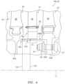
- Each of the stators 52 is or includes a fairing configured to form an axial portion of an inner peripheral boundary of the core gas path 44.
- the stator 52 (e.g., fairing) of FIG. 3 is configured having a monolithic full hoop body.
- This stator 52 for example, is formed as an integral, tubular body without any mechanically interconnected axial and/or circumferential segments.
- the assembly 48 of the present disclosure is not limited to the foregoing exemplary stator configuration.
- the stator 52 may be configured as an axially and/or circumferentially segmented body.
- the rotor 54 may be configured as or included in one of the rotors 30-34 (see FIG. 1 ); e.g., the HPC rotor 32.
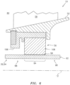
- This rotor 54 includes one or more arrays 87 of rotor blades 88, one or more rotor disks 90 (e.g., 90A, 90B, 90C) and one or more annular rotor disk linkages 92 (e.g., 92A, 92B).
- Each array 97 of rotor blades 88 includes a plurality of rotor blades, which are arranged circumferentially around and connected to the respective rotor disk 90.
- Each array of rotor blades 88 is positioned axially between neighboring arrays 51 of stator vanes 58.
- Each of the linkages 92 is configured to connect respective neighboring rotor disks 90 to one another.
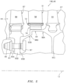
- the linkage 92A of FIG. 4 extends axially between and is connected to a respective adjacent pair of the rotor disks 90A and 90B.
- one or more of the linkages 92 may connect the rotor disk 90 to another component of the turbine engine 10 such as, for example, the high speed shaft.
- the linkage 92A may be formed integral with or bonded (e.g., welded, etc.) to the first rotor disk 90A at a first end of the linkage 92A.
- the linkage 92 may be removably attached to the second rotor disk 90B at a second end of the linkage 92A.
- the linkage 92A of FIG. 4 is attached to the second rotor disk 90B with one or more fasteners 93.
- the linkage 92A of FIG. 4 includes a flange connector 95A, which is mechanically fastened to the rotor disk 90A with a plurality of bolts 97 and nuts 99.
- the linkage 92 of the present disclosure may also or alternatively be attached to the second rotor disk 90B using one or more connections other than the exemplary bolted connection described above. Furthermore, while the first end of the linkage 92 is shown in FIG. 4 as being upstream of the second end, these ends and their respective connections may be reversed as generally shown, for example, in FIG. 5 .
- One or more parts 94, 95A, 98A and 98B of the linkage 92 (or the whole of the linkage 92A as shown in FIG. 4 ) has an outermost radius 101 which is sized less than an innermost radius 103 of the non-contact seal assembly 56 (e.g., the non-contact seal). In this manner, those parts 94, 95 and 98B of the linkage 92 may be inserted into and passed axially through the seal assembly 56 during assembly of the rotor 54.
- the parts of the linkage 92A includes an intermediate seal portion 94 and adj acent end portions 98A and 98B of the linkage 92A as well as the flange connector 95A.
- At least one of the parts of the linkage 92 (e.g., the end portion 98A) which need not be passed through the seal assembly 56 during assembly may have an outermost radius which is greater than the innermost radius 101.
- the seal portion 94 may have an outer cylindrical surface 96.
- the term “cylindrical” may describe a surface or part with a circular-annular cross-sectional geometry which extends substantially (e.g., only) axially along a centerline.
- a “conical” surface or part may also extend in a radial direction towards or away from the centerline.
- this seal portion 94 may, not according to the invention, have substantially the same radial thickness as one or more other portions of the linkage 92; e.g., the portions.
- the seal portion 94 is radially thicker than one or more adjacent portions 98A and 98B of the linkage 92.
- This additional thickness (e.g., seal region 100) is provided by forming a hardface on a base portion of the linkage 92, where the hardface forms the cylindrical surface 96.
- the hardface may by formed on the buildup of material, wherein the hardface material has a hardness value different than and harder than the base linkage material.
- This hardface material may be the same material as the base linkage material where, for example, that portion of the material is (e.g., heat) treated to increase its hardness.
- the hardface material may be different than the base linkage material beneath.
- the seal portion 94 of FIG. 7 has an axial length 102 that is greater than its radial thickness 104.
- the axial length 102 is greater than an axial length of the non-contact seal assembly 56.
- the additional thickness of the seal region 100 may be restored during a rebuild process by filling in wear grooves with additional material and/or removing some or all of the worn seal region 100 and forming a new seal region 100 in its place without compromising the linkage base portion beneath. This in turn may prolong the useful life of the linkage 92.
- the hardface may also provide a barrier to prevent incidental wear from progressing into a crack in the linkage 92.
- each of the seal assemblies 56 is arranged in a radial gap between a respective one of the stators 52 and a respective one of the linkages 92.
- Each of the seal assemblies 56 is configured to substantially seal the respective gap.
- the seal assembly 56 of FIGS. 3 and 6 for example, includes an annular carrier 106 and an annular non-contact seal 108 such as, but not limited to, a hydrostatic non-contact seal.
- the carrier 106 is configured to mount the non-contact seal 108 to the respective stator 52.
- the carrier 106 may be configured having a monolithic full hoop body.
- the carrier 106 for example, is formed as an integral, tubular body without any mechanically interconnected axial and/or circumferential segments.
- the assembly 48 of the present disclosure is not limited to the foregoing exemplary carrier configuration.
- the carrier 106 may be configured as an axially and/or circumferentially segmented body.
- the non-contact seal 108 includes one or more circumferentially spaced shoes 126 which are located in a non-contact position along the cylindrical surface 96 of the respective linkage 92.
- Each shoe 126 is formed with a sealing surface 128 and a slot 130 extending radially inwardly toward the sealing surface 128.
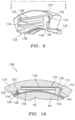
- the non-contact seal 108 includes one or more circumferentially spaced spring elements 132, the details of one of which are best seen in FIGS. 10 and 11 .
- Each spring element 132 is formed with an inner band 134 and an outer band 136 radially outwardly spaced from the inner band 134.
- One end of each of the bands 134 and 136 is mounted to or integrally formed with a stationary base 124 of the seal and the opposite end thereof is connected to a first stop 138.
- This base 124 may be configured as a monolithic full hoop body as best seen in FIG. 8 .
- the present disclosure is not limited to the aforesaid exemplary configuration.
- the first stop 138 includes a strip 140 which is connected to a shoe 126 (one of which is shown in FIGS. 11 and 12 ), and has an arm 142 opposite the shoe 126 which may be received within a recess 144 formed in the base 124.
- the recess 144 has a shoulder 146 positioned in alignment with the arm 142 of the first stop 138.
- a second stop 148 is connected to or integrally formed with the strip 140 and is connected to the shoe 126.
- the second stop 148 is circumferentially spaced from the first stop 138 in a position near the point at which the inner and outer bands 134 and 136 connect to the base 124.
- the second stop 148 is formed with an arm 150 which may be received within a recess 152 in the base 124.
- the recess 152 has a shoulder 154 positioned in alignment with the arm 150 of second stop 148.
- aerodynamic forces may be developed which apply a fluid pressure to the shoe 126 causing it to move radially with respect to the respective linkage 92.
- the fluid velocity increases as the gap 156 between the shoe 126 and respective linkage 92 increases, thus reducing pressure in the gap 156 and drawing the shoe 126 radially inwardly toward the rotor 54.
- the seal gap 156 closes, the velocity decreases and the pressure increases within the seal gap 156 thus forcing the shoe 126 radially outwardly from the rotor 54.
- the spring elements 132 deflect and move with the shoe 126 to create a primary seal of the circumferential gap 156 between the rotor 54 and base 124 within predetermined design tolerances.
- the first and second stops 138 and 148 may limit the extent of radially inward and outward movement of the shoe 126 with respect to the rotor 54 for safety and operational limitation.
- a gap is provided between the arm 142 of first stop 138 and the shoulder 146, and between the arm 150 of second stop 148 and shoulder 154, such that the shoe 126 can move radially inwardly relative to the rotor 54.
- Such inward motion is limited by engagement of the arms 142, 150 with shoulders 146 and 154, respectively, to prevent the shoe 126 from contacting the rotor 54 or exceeding design tolerances for the gap between the two.
- the arms 142 and 150 also contact the base 124 in the event the shoe 126 moves radially outwardly relative to the rotor 54, to limit movement of the shoe 126 in that direction.
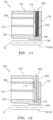
- the non-contact seal 108 is also provided with a secondary seal which may take the form of a brush seal 158, as shown in FIG. 11 , or a stack of at least two sealing elements oriented side-by-side and formed of thin sheets of metal or other suitable material as shown in FIGS. 12 and 13 .
- the brush seal 158 is positioned so that one end of its bristles 160 extends into the slot 130 formed in the shoe 126.
- the bristles 160 deflect with the radial inward and outward movement of the shoe 126, in response to the application of fluid pressure as noted above, in such a way as to create a secondary seal of the gap 156 between the rotor 54 and base 124.
- the secondary seal of this embodiment may include a stack of at least two sealing elements 162 and 164.
- Each of the sealing elements 162 and 164 includes an outer ring 166 formed with a plurality of circumferentially spaced openings 168, a spring member 170 mounted within each opening 168 and a plurality of inner ring segments 172 each connected to at least one of the spring members 170.
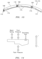
- the spring member 170 is depicted in FIG. 14 as a series of connected loops, but it should be understood that spring member 170 could take essentially any other form, including parallel bands as in the spring elements 132.
- the sealing elements 162 and 164 are oriented side-by-side and positioned so that the inner ring segments 172 extend into the slot 130 formed in the shoe 126.
- the spring members 170 deflect with the radial inward and outward movement of the shoe 126, in response to the application of fluid pressure as noted above, in such a way as to create a secondary seal of the gap 156 between the rotor 54 and base 124.
- the sealing elements 172 and 164 assist the spring elements 132 in maintaining the shoe 126 within design clearances relative to the rotor 54.
- One or more of the spring elements 162 and 164 may be formed of sheet metal or other suitable flexible, heat-resistant material.
- the sealing elements 162 and 164 may be attached to one another, such as by welding and/or any other bonding technique, a mechanical connection or the like, or they may positioned side-by-side within the slot 130 with no connection between them.
- adjacent sealing elements are arranged so that the outer ring 166 of one sealing element 162 covers the openings 168 in the adjacent sealing element 164.
- a front plate 174 may be positioned between the spring element 132 and the sealing element 162, and a back plate 176 may be located adjacent to the sealing element 164 for the purpose of assisting in supporting the sealing elements 162, 164 in position within the shoe 126.
- the non-contact seal 108 is subjected to aerodynamic forces as a result of the passage of air along the surface of the shoes 126 and the respective linkage 92 and, more particularly, the respective seal portion 94.
- the operation of non-contact seal 108 is dependent, in part, on the effect of these aerodynamic forces tending to lift the shoes 126 radially outwardly relative to the surface of rotor 54, and the counteracting forces imposed by the spring elements 132 and the secondary seals (e.g., brush seal 158 or the stacked seal formed by plates 162, 164) which tend to urge the shoes 126 in a direction toward the rotor 54.
- These forces acting on the shoe 126 are schematically depicted with arrows in FIG. 14 .
- These forces acting on the non-contact seal 108 may be balanced to ensure that nominal clearance is maintained.
- the present disclosure is not limited to the exemplary non-contact seal 108 described above.
- Various other non-contact seals are known in the art and may be reconfigured in light of the disclosure above to be included with the assembly 48 of the present disclosure.
- An example of such an alternative non-contact seal 108 is illustrated in FIG. 15 .
- Other examples of non-contact seals are disclosed in U.S. Patent No. 8,172,232 ; U.S. Patent No. 8,002,285 ; U.S. Patent No. 7,896,352 ; U.S. Patent No. 7,410,173 ; U.S. Patent No. 7,182,345 ; and U.S. Patent No. 6,428,009 .
- Still another example of a non-contact seal is a hydrodynamic non-contact seal.
- the assembly 48 may be included in various aircraft and industrial turbine engines other than the one described above as well as in other types of rotational equipment; e.g., wind turbines, water turbines, rotary engines, etc.
- the assembly 48 may be included in a geared turbine engine where a gear train connects one or more shafts to one or more rotors in a fan section, a compressor section and/or any other engine section.
- the assembly 48 may be included in a turbine engine configured without a gear train.
- the assembly 48 may be included in a geared or non-geared turbine engine configured with a single spool, with two spools (e.g., see FIG. 1 ), or with more than two spools.
- the turbine engine may be configured as a turbofan engine, a turbojet engine, a propfan engine, a pusher fan engine or any other type of turbine engine.
- the present invention therefore is not limited to any particular types or configurations of turbine engines or rotational equipment.
Landscapes
- Engineering & Computer Science (AREA)
- General Engineering & Computer Science (AREA)
- Mechanical Engineering (AREA)
- Aviation & Aerospace Engineering (AREA)
- Turbine Rotor Nozzle Sealing (AREA)
- Structures Of Non-Positive Displacement Pumps (AREA)
Claims (13)
- Anordnung für Drehausrüstung, wobei die Anordnung Folgendes umfasst:einen Stator (52);einen Rotor (54), der sich axial entlang einer Mittellinie (12) erstreckt, wobei der Rotor (54) eine Verbindung (92A), eine erste Rotorscheibe (90A) und eine zweite Rotorscheibe (90B) beinhaltet, wobei sich die Verbindung (92A) axial von der ersten Rotorscheibe (90A) zu der zweiten Rotorscheibe (90B) erstreckt; undeine Dichtungsanordnung (56), die eine hydrostatische kontaktlose Dichtung (108) beinhaltet,wobei die Dichtungsanordnung (56) zum radialen Abdichten eines Spalts zwischen dem Stator (52) und der Verbindung (92A) konfiguriert ist,wobei die kontaktlose Dichtung (108) direkt radial über einer zylindrischen Fläche (96) eines Dichtungsabschnitts (94) der Verbindung (92A) positioniert und axial mit dieser ausgerichtet ist undwobei die kontaktlose Dichtung Folgendes umfasst:eine ringförmige Basis (124);eine Vielzahl von Schuhen (126), die um die Verbindung (92A) herum und radial benachbart zu dieser angeordnet ist; undeine Vielzahl von Federelementen (132), wobei jedes der Federelemente (132) radial zwischen einem jeweiligen der Schuhe (126) und der Basis (124) liegt und diese verbindet,dadurch gekennzeichnet, dass:die Verbindung (92A) abnehmbar an der zweiten Rotorscheibe (90B) angebracht ist undder Dichtungsabschnitt (94) der Verbindung (92A) eine Hartbeschichtung aufweist, die die zylindrische Fläche (96) bildet, wobei der Dichtungsabschnitt (94) der Verbindung (92A) radial um eine zusätzliche Dicke dicker ist als benachbarte Abschnitte der Verbindung (92A), wobei die Hartbeschichtung einen Abschnitt der zusätzlichen Dicke bereitstellt.
- Anordnung nach Anspruch 1, wobei die Basis (124) mit einem monolithischen Vollringkörper konfiguriert ist.
- Anordnung nach Anspruch 1 oder 2, ferner umfassend einen Träger (106), der die kontaktlose Dichtung mit dem Stator (52) verbindet, wobei der Träger (106) mit einem monolithischen Vollringkörper konfiguriert ist.
- Anordnung nach einem der vorhergehenden Ansprüche, wobei der Stator (52) mit einem monolithischen Vollringkörper konfiguriert ist.
- Anordnung nach einem der vorhergehenden Ansprüche, wobei der Stator (52) eine Verkleidung umfasst, die dazu konfiguriert ist, einen axialen Abschnitt einer inneren Umfangsbegrenzung eines Kerngaspfads (44) durch die Drehausrüstung zu bilden, und die Drehausrüstung als ein Gasturbinentriebwerk (10) konfiguriert ist.
- Anordnung nach einem der vorhergehenden Ansprüche, ferner umfassend:eine Vielzahl von ersten Rotorblättern (88), die um die erste Rotorscheibe (90A) herum angeordnet und mit dieser verbunden ist;eine Vielzahl von zweiten Rotorblättern (88), die um die zweite Rotorscheibe (90B) herum angeordnet und mit dieser verbunden ist; undeine Vielzahl von Statorschaufeln (58), die um den Stator (52) herum angeordnet und mit diesem verbunden ist, wobei sich die Statorschaufeln (58) axial zwischen den ersten Rotorblättern (88) und den zweiten Rotorblättern (88) befinden.
- Anordnung nach einem der vorhergehenden Ansprüche, wobei die Verbindung (92A) einen Flanschverbinder (95A) beinhaltet, der mit einem oder mehreren Befestigungselementen an der zweiten Rotorscheibe (90B) angebracht ist, der Flanschverbinder (95A) einen äußersten Radius aufweist und die kontaktlose Dichtung (108) einen innersten Radius (103) aufweist, der größer als der äußerste Radius ist.
- Anordnung nach einem der vorhergehenden Ansprüche, wobei die Verbindung (92A) einen äußersten Radius (101) aufweist und die kontaktlose Dichtung (108) einen innersten Radius (103) aufweist, der größer als der äußerste Radius (101) ist.
- Anordnung nach einem der vorhergehenden Ansprüche, wobei die Verbindung (92A) oder ein Abschnitt davon dazu konfiguriert ist, während der Montage teilweise, z. B. axial, durch die kontaktlose Dichtung (108) zu verlaufen.
- Luftfahrzeugantriebssystem, umfassend:
ein Gasturbinentriebwerk (10), das einen Verdichterbereich (19), der den Stator umfasst, der mit einem monolithischen Vollringkörper konfiguriert ist, und eine Anordnung nach einem der vorhergehenden Ansprüche beinhaltet. - Gasturbinentriebwerk, das die Anordnung nach Anspruch 1 umfasst, und ferner umfassend:
eine ringförmige Verkleidung axial zwischen der ersten Rotorscheibe (90A) und der zweiten Rotorscheibe (90B); wobei:die Verbindung (92A) ringförmig und mechanisch an der zweiten Rotorscheibe (90B) befestigt ist; undder Spalt zwischen der Verkleidung und der Verbindung (92A) gebildet ist, wobei die kontaktlose Dichtung (108) in dem Spalt konfiguriert ist und wobei die Basis (124) an der Verkleidung montiert ist, wobei die Schuhe (126) in Umfangsrichtung um die zylindrische Fläche (96) herum und radial benachbart zu dieser angeordnet sind und wobei jedes der Federelemente (132) radial zwischen einem jeweiligen der Schuhe (126) und der Basis (124) liegt und diese verbindet. - Gasturbinentriebwerk nach Anspruch 11, ferner umfassend einen Träger (106), der die Basis (124) an der Verkleidung montiert, wobei der Träger (106) mit einem monolithischen Vollringkörper konfiguriert ist.
- Gasturbinentriebwerk nach Anspruch 11 oder 12, wobei die Verkleidung mit einem monolithischen Vollringkörper konfiguriert ist und wobei die Basis (124) mit einem monolithischen Vollringkörper konfiguriert ist.
Applications Claiming Priority (1)
| Application Number | Priority Date | Filing Date | Title |
|---|---|---|---|
| US14/794,516 US10794208B2 (en) | 2015-07-08 | 2015-07-08 | Non-contact seal assembly for rotational equipment with linkage between adjacent rotors |
Publications (2)
| Publication Number | Publication Date |
|---|---|
| EP3115659A1 EP3115659A1 (de) | 2017-01-11 |
| EP3115659B1 true EP3115659B1 (de) | 2024-09-18 |
Family
ID=56800119
Family Applications (1)
| Application Number | Title | Priority Date | Filing Date |
|---|---|---|---|
| EP16178693.4A Active EP3115659B1 (de) | 2015-07-08 | 2016-07-08 | Kontaktlose dichtungsanordnung für eine drehausrüstung mit verbindung zwischen benachbarten rotoren |
Country Status (2)
| Country | Link |
|---|---|
| US (1) | US10794208B2 (de) |
| EP (1) | EP3115659B1 (de) |
Families Citing this family (16)
| Publication number | Priority date | Publication date | Assignee | Title |
|---|---|---|---|---|
| US10358932B2 (en) | 2015-06-29 | 2019-07-23 | United Technologies Corporation | Segmented non-contact seal assembly for rotational equipment |
| US20170051751A1 (en) * | 2015-08-19 | 2017-02-23 | United Technologies Corporation | Seal assembly for rotational equipment |
| US10718270B2 (en) * | 2017-06-15 | 2020-07-21 | Raytheon Technologies Corporation | Hydrostatic non-contact seal with dual material |
| US10830081B2 (en) * | 2017-07-17 | 2020-11-10 | Raytheon Technologies Corporation | Non-contact seal with non-straight spring beam(s) |
| US10184347B1 (en) * | 2017-07-18 | 2019-01-22 | United Technologies Corporation | Non-contact seal with resilient biasing element(s) |
| US10746039B2 (en) * | 2017-09-25 | 2020-08-18 | United Technologies Corporation | Hydrostatic seal pinned cartridge |
| US11421543B2 (en) * | 2018-11-28 | 2022-08-23 | Raytheon Technologies Corporation | Hydrostatic seal with asymmetric beams for anti-tipping |
| US11674402B2 (en) | 2018-11-28 | 2023-06-13 | Raytheon Technologies Corporation | Hydrostatic seal with non-parallel beams for anti-tipping |
| US11415227B2 (en) | 2019-08-21 | 2022-08-16 | Raytheon Technologies Corporation | Non-contact seal assembly with chamfered seal shoe |
| EP3783249B1 (de) * | 2019-08-23 | 2023-07-12 | Raytheon Technologies Corporation | Berührungslose dichtung mit axialer anordnung |
| US11215056B2 (en) * | 2020-04-09 | 2022-01-04 | Raytheon Technologies Corporation | Thermally isolated rotor systems and methods |
| US11773738B2 (en) * | 2021-12-09 | 2023-10-03 | Rtx Corporation | Radial lift seal |
| FR3146933A1 (fr) * | 2023-03-23 | 2024-09-27 | Safran Aircraft Engines | Joint annulaire hydrostatique |
| FR3146942A1 (fr) * | 2023-03-23 | 2024-09-27 | Safran Aircraft Engines | Joint annulaire hydrostatique |
| FR3146940A1 (fr) * | 2023-03-23 | 2024-09-27 | Safran Aircraft Engines | Ensemble statorique pour une turbomachine d’aéronef |
| US12372002B2 (en) * | 2023-03-24 | 2025-07-29 | General Electric Company | Seal support assembly for a turbine engine |
Family Cites Families (27)
| Publication number | Priority date | Publication date | Assignee | Title |
|---|---|---|---|---|
| US2681788A (en) * | 1951-05-23 | 1954-06-22 | Solar Aircraft Co | Gas turbine vane structure |
| US3849023A (en) * | 1973-06-28 | 1974-11-19 | Gen Electric | Stator assembly |
| DE3828833A1 (de) * | 1988-08-25 | 1990-03-01 | Mtu Muenchen Gmbh | Einrichtung zur abdichtung von durch medien, wie fluessigkeiten und/oder gasen, unterschiedlichen druckes beaufschlagten raeumen, insbesondere fuer turbomaschinen |
| FR2805042B1 (fr) * | 2000-02-11 | 2002-09-06 | Metravib Sa | Procede et dispositif non intrusif pour caracteriser les perturbations d'ecoulement d'un fluide a l'interieur d'une canalisation |
| US6428009B2 (en) | 2000-04-03 | 2002-08-06 | John F. Justak | Robust hydrodynamic brush seal |
| US6612581B2 (en) * | 2001-12-04 | 2003-09-02 | General Electric Company | Brush seal coil for rotary machinery and method of retrofitting |
| US20040015016A1 (en) * | 2002-07-22 | 2004-01-22 | Huntsman Petrochemical Corporation | Preparation of secondary amines |
| GB0226685D0 (en) * | 2002-11-15 | 2002-12-24 | Rolls Royce Plc | Sealing arrangement |
| US8172232B2 (en) * | 2003-05-01 | 2012-05-08 | Advanced Technologies Group, Inc. | Non-contact seal for a gas turbine engine |
| US20040217549A1 (en) | 2003-05-01 | 2004-11-04 | Justak John F. | Hydrodynamic brush seal |
| US7410173B2 (en) | 2003-05-01 | 2008-08-12 | Justak John F | Hydrodynamic brush seal |
| US8641045B2 (en) | 2003-05-01 | 2014-02-04 | Advanced Technologies Group, Inc. | Seal with stacked sealing elements |
| US7896352B2 (en) | 2003-05-01 | 2011-03-01 | Justak John F | Seal with stacked sealing elements |
| US8002285B2 (en) | 2003-05-01 | 2011-08-23 | Justak John F | Non-contact seal for a gas turbine engine |
| US8050874B2 (en) * | 2004-06-14 | 2011-11-01 | Papadimitriou Wanda G | Autonomous remaining useful life estimation |
| US20080048398A1 (en) * | 2006-08-24 | 2008-02-28 | United Technologies Corporation | Gap sealing arrangement |
| US7927069B2 (en) | 2006-11-13 | 2011-04-19 | United Technologies Corporation | Hoop seal with partial slot geometry |
| US8109717B2 (en) | 2007-08-17 | 2012-02-07 | United Technologies Corp. | Gas turbine engine systems involving hydrostatic face seals with integrated back-up seals |
| US8109716B2 (en) | 2007-08-17 | 2012-02-07 | United Technologies Corp. | Gas turbine engine systems involving hydrostatic face seals with anti-fouling provisioning |
| US8105021B2 (en) | 2007-08-20 | 2012-01-31 | United Technologies Corp. | Gas turbine engine systems involving hydrostatic face seals with integrated back-up seals |
| US7797941B2 (en) | 2007-10-26 | 2010-09-21 | United Technologies Corporation | Gas turbine engine systems involving hydrostatic face seals |
| FR2926612B1 (fr) | 2008-01-23 | 2012-12-28 | Snecma | Tambour de rotor pour une turbomachine |
| US8167545B2 (en) | 2008-02-27 | 2012-05-01 | United Technologies Corp. | Self-balancing face seals and gas turbine engine systems involving such seals |
| BRPI0912709A2 (pt) | 2008-05-13 | 2015-10-13 | Bae Systems Plc | componente conjugado para encaixar com um projétil, e, aparelho e método para lançar um veículo dotado de asa |
| US20140321993A1 (en) * | 2011-01-07 | 2014-10-30 | General Electric Company | Elliptical sealing system |
| US20130106061A1 (en) * | 2011-10-28 | 2013-05-02 | General Electric Company | High temperature seal system |
| EP2971692B1 (de) * | 2013-03-15 | 2020-02-12 | United Technologies Corporation | Schwingungsdämpfende vorrichtung für hydrostatische dichtung eines gasturbinenmotors |
-
2015
- 2015-07-08 US US14/794,516 patent/US10794208B2/en active Active
-
2016
- 2016-07-08 EP EP16178693.4A patent/EP3115659B1/de active Active
Also Published As
| Publication number | Publication date |
|---|---|
| US10794208B2 (en) | 2020-10-06 |
| EP3115659A1 (de) | 2017-01-11 |
| US20170009596A1 (en) | 2017-01-12 |
Similar Documents
| Publication | Publication Date | Title |
|---|---|---|
| EP3115659B1 (de) | Kontaktlose dichtungsanordnung für eine drehausrüstung mit verbindung zwischen benachbarten rotoren | |
| US11168574B2 (en) | Segmented non-contact seal assembly for rotational equipment | |
| US10975715B2 (en) | Non-contact seal assembly for rotational equipment | |
| US10669888B2 (en) | Non-contact seal assembly for rotational equipment | |
| EP3133239B1 (de) | Anordnung für rotierende apparatur | |
| EP3196518B1 (de) | Dichtungsschuh für eine hydrostatische kontaktfreie dichtungsvorrichtung | |
| EP3447344B1 (de) | Hydrostatische kontaktfreie dichtung aus zwei werkstoffen | |
| EP3418610B1 (de) | Hydrostatische berührungslose dichtung mit gewichtsreduzierungstasche | |
| EP3594452B1 (de) | Dichtungssegment für einen gasturbinenmotor | |
| EP3415798B1 (de) | Hydrostatische berührungslose dichtung mit unterschiedlich dicken federbalken | |
| EP3431836B1 (de) | Berührungslose dichtung mit nicht-geraden federbalken | |
| EP3290755A1 (de) | Schwimmende, kontaktfreie dichtung mit mindestens drei leisten | |
| EP3428489B1 (de) | Hydrostatische berührungslose dichtung mit dichtungsträgerbeseitigung | |
| EP3428490A1 (de) | Hydrostatische berührungslose dichtung mit versetztem aussenring | |
| EP3409885B1 (de) | Federdichtung mit ablenkung |
Legal Events
| Date | Code | Title | Description |
|---|---|---|---|
| PUAI | Public reference made under article 153(3) epc to a published international application that has entered the european phase |
Free format text: ORIGINAL CODE: 0009012 |
|
| STAA | Information on the status of an ep patent application or granted ep patent |
Free format text: STATUS: THE APPLICATION HAS BEEN PUBLISHED |
|
| AK | Designated contracting states |
Kind code of ref document: A1 Designated state(s): AL AT BE BG CH CY CZ DE DK EE ES FI FR GB GR HR HU IE IS IT LI LT LU LV MC MK MT NL NO PL PT RO RS SE SI SK SM TR |
|
| AX | Request for extension of the european patent |
Extension state: BA ME |
|
| STAA | Information on the status of an ep patent application or granted ep patent |
Free format text: STATUS: REQUEST FOR EXAMINATION WAS MADE |
|
| 17P | Request for examination filed |
Effective date: 20170711 |
|
| RBV | Designated contracting states (corrected) |
Designated state(s): AL AT BE BG CH CY CZ DE DK EE ES FI FR GB GR HR HU IE IS IT LI LT LU LV MC MK MT NL NO PL PT RO RS SE SI SK SM TR |
|
| STAA | Information on the status of an ep patent application or granted ep patent |
Free format text: STATUS: EXAMINATION IS IN PROGRESS |
|
| 17Q | First examination report despatched |
Effective date: 20190115 |
|
| RAP1 | Party data changed (applicant data changed or rights of an application transferred) |
Owner name: RAYTHEON TECHNOLOGIES CORPORATION |
|
| RAP3 | Party data changed (applicant data changed or rights of an application transferred) |
Owner name: RTX CORPORATION |
|
| GRAP | Despatch of communication of intention to grant a patent |
Free format text: ORIGINAL CODE: EPIDOSNIGR1 |
|
| STAA | Information on the status of an ep patent application or granted ep patent |
Free format text: STATUS: GRANT OF PATENT IS INTENDED |
|
| INTG | Intention to grant announced |
Effective date: 20240411 |
|
| GRAS | Grant fee paid |
Free format text: ORIGINAL CODE: EPIDOSNIGR3 |
|
| GRAA | (expected) grant |
Free format text: ORIGINAL CODE: 0009210 |
|
| STAA | Information on the status of an ep patent application or granted ep patent |
Free format text: STATUS: THE PATENT HAS BEEN GRANTED |
|
| AK | Designated contracting states |
Kind code of ref document: B1 Designated state(s): AL AT BE BG CH CY CZ DE DK EE ES FI FR GB GR HR HU IE IS IT LI LT LU LV MC MK MT NL NO PL PT RO RS SE SI SK SM TR |
|
| REG | Reference to a national code |
Ref country code: GB Ref legal event code: FG4D |
|
| REG | Reference to a national code |
Ref country code: CH Ref legal event code: EP |
|
| REG | Reference to a national code |
Ref country code: IE Ref legal event code: FG4D |
|
| REG | Reference to a national code |
Ref country code: DE Ref legal event code: R096 Ref document number: 602016089429 Country of ref document: DE |
|
| REG | Reference to a national code |
Ref country code: LT Ref legal event code: MG9D |
|
| PG25 | Lapsed in a contracting state [announced via postgrant information from national office to epo] |
Ref country code: NO Free format text: LAPSE BECAUSE OF FAILURE TO SUBMIT A TRANSLATION OF THE DESCRIPTION OR TO PAY THE FEE WITHIN THE PRESCRIBED TIME-LIMIT Effective date: 20241218 |
|
| PG25 | Lapsed in a contracting state [announced via postgrant information from national office to epo] |
Ref country code: GR Free format text: LAPSE BECAUSE OF FAILURE TO SUBMIT A TRANSLATION OF THE DESCRIPTION OR TO PAY THE FEE WITHIN THE PRESCRIBED TIME-LIMIT Effective date: 20241219 Ref country code: FI Free format text: LAPSE BECAUSE OF FAILURE TO SUBMIT A TRANSLATION OF THE DESCRIPTION OR TO PAY THE FEE WITHIN THE PRESCRIBED TIME-LIMIT Effective date: 20240918 |
|
| PG25 | Lapsed in a contracting state [announced via postgrant information from national office to epo] |
Ref country code: BG Free format text: LAPSE BECAUSE OF FAILURE TO SUBMIT A TRANSLATION OF THE DESCRIPTION OR TO PAY THE FEE WITHIN THE PRESCRIBED TIME-LIMIT Effective date: 20240918 |
|
| PG25 | Lapsed in a contracting state [announced via postgrant information from national office to epo] |
Ref country code: LV Free format text: LAPSE BECAUSE OF FAILURE TO SUBMIT A TRANSLATION OF THE DESCRIPTION OR TO PAY THE FEE WITHIN THE PRESCRIBED TIME-LIMIT Effective date: 20240918 |
|
| PG25 | Lapsed in a contracting state [announced via postgrant information from national office to epo] |
Ref country code: HR Free format text: LAPSE BECAUSE OF FAILURE TO SUBMIT A TRANSLATION OF THE DESCRIPTION OR TO PAY THE FEE WITHIN THE PRESCRIBED TIME-LIMIT Effective date: 20240918 |
|
| REG | Reference to a national code |
Ref country code: NL Ref legal event code: MP Effective date: 20240918 |
|
| PG25 | Lapsed in a contracting state [announced via postgrant information from national office to epo] |
Ref country code: RS Free format text: LAPSE BECAUSE OF FAILURE TO SUBMIT A TRANSLATION OF THE DESCRIPTION OR TO PAY THE FEE WITHIN THE PRESCRIBED TIME-LIMIT Effective date: 20241218 |
|
| PG25 | Lapsed in a contracting state [announced via postgrant information from national office to epo] |
Ref country code: RS Free format text: LAPSE BECAUSE OF FAILURE TO SUBMIT A TRANSLATION OF THE DESCRIPTION OR TO PAY THE FEE WITHIN THE PRESCRIBED TIME-LIMIT Effective date: 20241218 Ref country code: NO Free format text: LAPSE BECAUSE OF FAILURE TO SUBMIT A TRANSLATION OF THE DESCRIPTION OR TO PAY THE FEE WITHIN THE PRESCRIBED TIME-LIMIT Effective date: 20241218 Ref country code: LV Free format text: LAPSE BECAUSE OF FAILURE TO SUBMIT A TRANSLATION OF THE DESCRIPTION OR TO PAY THE FEE WITHIN THE PRESCRIBED TIME-LIMIT Effective date: 20240918 Ref country code: HR Free format text: LAPSE BECAUSE OF FAILURE TO SUBMIT A TRANSLATION OF THE DESCRIPTION OR TO PAY THE FEE WITHIN THE PRESCRIBED TIME-LIMIT Effective date: 20240918 Ref country code: GR Free format text: LAPSE BECAUSE OF FAILURE TO SUBMIT A TRANSLATION OF THE DESCRIPTION OR TO PAY THE FEE WITHIN THE PRESCRIBED TIME-LIMIT Effective date: 20241219 Ref country code: FI Free format text: LAPSE BECAUSE OF FAILURE TO SUBMIT A TRANSLATION OF THE DESCRIPTION OR TO PAY THE FEE WITHIN THE PRESCRIBED TIME-LIMIT Effective date: 20240918 Ref country code: BG Free format text: LAPSE BECAUSE OF FAILURE TO SUBMIT A TRANSLATION OF THE DESCRIPTION OR TO PAY THE FEE WITHIN THE PRESCRIBED TIME-LIMIT Effective date: 20240918 |
|
| REG | Reference to a national code |
Ref country code: AT Ref legal event code: MK05 Ref document number: 1724943 Country of ref document: AT Kind code of ref document: T Effective date: 20240918 |
|
| PG25 | Lapsed in a contracting state [announced via postgrant information from national office to epo] |
Ref country code: NL Free format text: LAPSE BECAUSE OF FAILURE TO SUBMIT A TRANSLATION OF THE DESCRIPTION OR TO PAY THE FEE WITHIN THE PRESCRIBED TIME-LIMIT Effective date: 20240918 |
|
| PG25 | Lapsed in a contracting state [announced via postgrant information from national office to epo] |
Ref country code: IS Free format text: LAPSE BECAUSE OF FAILURE TO SUBMIT A TRANSLATION OF THE DESCRIPTION OR TO PAY THE FEE WITHIN THE PRESCRIBED TIME-LIMIT Effective date: 20250118 Ref country code: PT Free format text: LAPSE BECAUSE OF FAILURE TO SUBMIT A TRANSLATION OF THE DESCRIPTION OR TO PAY THE FEE WITHIN THE PRESCRIBED TIME-LIMIT Effective date: 20250120 |
|
| PG25 | Lapsed in a contracting state [announced via postgrant information from national office to epo] |
Ref country code: RO Free format text: LAPSE BECAUSE OF FAILURE TO SUBMIT A TRANSLATION OF THE DESCRIPTION OR TO PAY THE FEE WITHIN THE PRESCRIBED TIME-LIMIT Effective date: 20240918 Ref country code: SM Free format text: LAPSE BECAUSE OF FAILURE TO SUBMIT A TRANSLATION OF THE DESCRIPTION OR TO PAY THE FEE WITHIN THE PRESCRIBED TIME-LIMIT Effective date: 20240918 |
|
| PG25 | Lapsed in a contracting state [announced via postgrant information from national office to epo] |
Ref country code: ES Free format text: LAPSE BECAUSE OF FAILURE TO SUBMIT A TRANSLATION OF THE DESCRIPTION OR TO PAY THE FEE WITHIN THE PRESCRIBED TIME-LIMIT Effective date: 20240918 |
|
| PG25 | Lapsed in a contracting state [announced via postgrant information from national office to epo] |
Ref country code: EE Free format text: LAPSE BECAUSE OF FAILURE TO SUBMIT A TRANSLATION OF THE DESCRIPTION OR TO PAY THE FEE WITHIN THE PRESCRIBED TIME-LIMIT Effective date: 20240918 Ref country code: AT Free format text: LAPSE BECAUSE OF FAILURE TO SUBMIT A TRANSLATION OF THE DESCRIPTION OR TO PAY THE FEE WITHIN THE PRESCRIBED TIME-LIMIT Effective date: 20240918 |
|
| PG25 | Lapsed in a contracting state [announced via postgrant information from national office to epo] |
Ref country code: PL Free format text: LAPSE BECAUSE OF FAILURE TO SUBMIT A TRANSLATION OF THE DESCRIPTION OR TO PAY THE FEE WITHIN THE PRESCRIBED TIME-LIMIT Effective date: 20240918 Ref country code: CZ Free format text: LAPSE BECAUSE OF FAILURE TO SUBMIT A TRANSLATION OF THE DESCRIPTION OR TO PAY THE FEE WITHIN THE PRESCRIBED TIME-LIMIT Effective date: 20240918 |
|
| PG25 | Lapsed in a contracting state [announced via postgrant information from national office to epo] |
Ref country code: IT Free format text: LAPSE BECAUSE OF FAILURE TO SUBMIT A TRANSLATION OF THE DESCRIPTION OR TO PAY THE FEE WITHIN THE PRESCRIBED TIME-LIMIT Effective date: 20240918 Ref country code: SK Free format text: LAPSE BECAUSE OF FAILURE TO SUBMIT A TRANSLATION OF THE DESCRIPTION OR TO PAY THE FEE WITHIN THE PRESCRIBED TIME-LIMIT Effective date: 20240918 |
|
| REG | Reference to a national code |
Ref country code: DE Ref legal event code: R097 Ref document number: 602016089429 Country of ref document: DE |
|
| PG25 | Lapsed in a contracting state [announced via postgrant information from national office to epo] |
Ref country code: DK Free format text: LAPSE BECAUSE OF FAILURE TO SUBMIT A TRANSLATION OF THE DESCRIPTION OR TO PAY THE FEE WITHIN THE PRESCRIBED TIME-LIMIT Effective date: 20240918 |
|
| PGFP | Annual fee paid to national office [announced via postgrant information from national office to epo] |
Ref country code: GB Payment date: 20250619 Year of fee payment: 10 |
|
| PGFP | Annual fee paid to national office [announced via postgrant information from national office to epo] |
Ref country code: FR Payment date: 20250619 Year of fee payment: 10 |
|
| PLBE | No opposition filed within time limit |
Free format text: ORIGINAL CODE: 0009261 |
|
| STAA | Information on the status of an ep patent application or granted ep patent |
Free format text: STATUS: NO OPPOSITION FILED WITHIN TIME LIMIT |
|
| 26N | No opposition filed |
Effective date: 20250619 |
|
| PG25 | Lapsed in a contracting state [announced via postgrant information from national office to epo] |
Ref country code: SE Free format text: LAPSE BECAUSE OF FAILURE TO SUBMIT A TRANSLATION OF THE DESCRIPTION OR TO PAY THE FEE WITHIN THE PRESCRIBED TIME-LIMIT Effective date: 20240918 |
|
| PGFP | Annual fee paid to national office [announced via postgrant information from national office to epo] |
Ref country code: DE Payment date: 20250620 Year of fee payment: 10 |