EP3115584A1 - Direct injection combustion engine of self-ignition type - Google Patents
Direct injection combustion engine of self-ignition type Download PDFInfo
- Publication number
- EP3115584A1 EP3115584A1 EP16177925.1A EP16177925A EP3115584A1 EP 3115584 A1 EP3115584 A1 EP 3115584A1 EP 16177925 A EP16177925 A EP 16177925A EP 3115584 A1 EP3115584 A1 EP 3115584A1
- Authority
- EP
- European Patent Office
- Prior art keywords
- fuel
- pressure
- combustion engine
- internal combustion
- direct injection
- Prior art date
- Legal status (The legal status is an assumption and is not a legal conclusion. Google has not performed a legal analysis and makes no representation as to the accuracy of the status listed.)
- Withdrawn
Links
Images
Classifications
-
- F—MECHANICAL ENGINEERING; LIGHTING; HEATING; WEAPONS; BLASTING
- F02—COMBUSTION ENGINES; HOT-GAS OR COMBUSTION-PRODUCT ENGINE PLANTS
- F02D—CONTROLLING COMBUSTION ENGINES
- F02D41/00—Electrical control of supply of combustible mixture or its constituents
- F02D41/02—Circuit arrangements for generating control signals
- F02D41/04—Introducing corrections for particular operating conditions
- F02D41/06—Introducing corrections for particular operating conditions for engine starting or warming up
- F02D41/062—Introducing corrections for particular operating conditions for engine starting or warming up for starting
- F02D41/064—Introducing corrections for particular operating conditions for engine starting or warming up for starting at cold start
-
- F—MECHANICAL ENGINEERING; LIGHTING; HEATING; WEAPONS; BLASTING
- F02—COMBUSTION ENGINES; HOT-GAS OR COMBUSTION-PRODUCT ENGINE PLANTS
- F02D—CONTROLLING COMBUSTION ENGINES
- F02D19/00—Controlling engines characterised by their use of non-liquid fuels, pluralities of fuels, or non-fuel substances added to the combustible mixtures
- F02D19/06—Controlling engines characterised by their use of non-liquid fuels, pluralities of fuels, or non-fuel substances added to the combustible mixtures peculiar to engines working with pluralities of fuels, e.g. alternatively with light and heavy fuel oil, other than engines indifferent to the fuel consumed
- F02D19/0639—Controlling engines characterised by their use of non-liquid fuels, pluralities of fuels, or non-fuel substances added to the combustible mixtures peculiar to engines working with pluralities of fuels, e.g. alternatively with light and heavy fuel oil, other than engines indifferent to the fuel consumed characterised by the type of fuels
- F02D19/0649—Liquid fuels having different boiling temperatures, volatilities, densities, viscosities, cetane or octane numbers
- F02D19/0652—Biofuels, e.g. plant oils
-
- F—MECHANICAL ENGINEERING; LIGHTING; HEATING; WEAPONS; BLASTING
- F02—COMBUSTION ENGINES; HOT-GAS OR COMBUSTION-PRODUCT ENGINE PLANTS
- F02D—CONTROLLING COMBUSTION ENGINES
- F02D41/00—Electrical control of supply of combustible mixture or its constituents
- F02D41/30—Controlling fuel injection
- F02D41/38—Controlling fuel injection of the high pressure type
- F02D41/3809—Common rail control systems
- F02D41/3836—Controlling the fuel pressure
-
- F—MECHANICAL ENGINEERING; LIGHTING; HEATING; WEAPONS; BLASTING
- F02—COMBUSTION ENGINES; HOT-GAS OR COMBUSTION-PRODUCT ENGINE PLANTS
- F02D—CONTROLLING COMBUSTION ENGINES
- F02D19/00—Controlling engines characterised by their use of non-liquid fuels, pluralities of fuels, or non-fuel substances added to the combustible mixtures
- F02D19/06—Controlling engines characterised by their use of non-liquid fuels, pluralities of fuels, or non-fuel substances added to the combustible mixtures peculiar to engines working with pluralities of fuels, e.g. alternatively with light and heavy fuel oil, other than engines indifferent to the fuel consumed
- F02D19/0602—Control of components of the fuel supply system
- F02D19/0605—Control of components of the fuel supply system to adjust the fuel pressure or temperature
-
- F—MECHANICAL ENGINEERING; LIGHTING; HEATING; WEAPONS; BLASTING
- F02—COMBUSTION ENGINES; HOT-GAS OR COMBUSTION-PRODUCT ENGINE PLANTS
- F02D—CONTROLLING COMBUSTION ENGINES
- F02D19/00—Controlling engines characterised by their use of non-liquid fuels, pluralities of fuels, or non-fuel substances added to the combustible mixtures
- F02D19/06—Controlling engines characterised by their use of non-liquid fuels, pluralities of fuels, or non-fuel substances added to the combustible mixtures peculiar to engines working with pluralities of fuels, e.g. alternatively with light and heavy fuel oil, other than engines indifferent to the fuel consumed
- F02D19/0626—Measuring or estimating parameters related to the fuel supply system
- F02D19/0634—Determining a density, viscosity, composition or concentration
-
- F—MECHANICAL ENGINEERING; LIGHTING; HEATING; WEAPONS; BLASTING
- F02—COMBUSTION ENGINES; HOT-GAS OR COMBUSTION-PRODUCT ENGINE PLANTS
- F02D—CONTROLLING COMBUSTION ENGINES
- F02D19/00—Controlling engines characterised by their use of non-liquid fuels, pluralities of fuels, or non-fuel substances added to the combustible mixtures
- F02D19/06—Controlling engines characterised by their use of non-liquid fuels, pluralities of fuels, or non-fuel substances added to the combustible mixtures peculiar to engines working with pluralities of fuels, e.g. alternatively with light and heavy fuel oil, other than engines indifferent to the fuel consumed
- F02D19/0663—Details on the fuel supply system, e.g. tanks, valves, pipes, pumps, rails, injectors or mixers
- F02D19/0673—Valves; Pressure or flow regulators; Mixers
- F02D19/0678—Pressure or flow regulators therefor; Fuel metering valves therefor
-
- F—MECHANICAL ENGINEERING; LIGHTING; HEATING; WEAPONS; BLASTING
- F02—COMBUSTION ENGINES; HOT-GAS OR COMBUSTION-PRODUCT ENGINE PLANTS
- F02D—CONTROLLING COMBUSTION ENGINES
- F02D2200/00—Input parameters for engine control
- F02D2200/02—Input parameters for engine control the parameters being related to the engine
- F02D2200/021—Engine temperature
-
- F—MECHANICAL ENGINEERING; LIGHTING; HEATING; WEAPONS; BLASTING
- F02—COMBUSTION ENGINES; HOT-GAS OR COMBUSTION-PRODUCT ENGINE PLANTS
- F02D—CONTROLLING COMBUSTION ENGINES
- F02D2200/00—Input parameters for engine control
- F02D2200/02—Input parameters for engine control the parameters being related to the engine
- F02D2200/06—Fuel or fuel supply system parameters
- F02D2200/0611—Fuel type, fuel composition or fuel quality
-
- F—MECHANICAL ENGINEERING; LIGHTING; HEATING; WEAPONS; BLASTING
- F02—COMBUSTION ENGINES; HOT-GAS OR COMBUSTION-PRODUCT ENGINE PLANTS
- F02D—CONTROLLING COMBUSTION ENGINES
- F02D41/00—Electrical control of supply of combustible mixture or its constituents
- F02D41/0025—Controlling engines characterised by use of non-liquid fuels, pluralities of fuels, or non-fuel substances added to the combustible mixtures
-
- F—MECHANICAL ENGINEERING; LIGHTING; HEATING; WEAPONS; BLASTING
- F02—COMBUSTION ENGINES; HOT-GAS OR COMBUSTION-PRODUCT ENGINE PLANTS
- F02D—CONTROLLING COMBUSTION ENGINES
- F02D41/00—Electrical control of supply of combustible mixture or its constituents
- F02D41/30—Controlling fuel injection
- F02D41/38—Controlling fuel injection of the high pressure type
- F02D41/3809—Common rail control systems
- F02D41/3836—Controlling the fuel pressure
- F02D41/3845—Controlling the fuel pressure by controlling the flow into the common rail, e.g. the amount of fuel pumped
- F02D41/3854—Controlling the fuel pressure by controlling the flow into the common rail, e.g. the amount of fuel pumped with elements in the low pressure part, e.g. low pressure pump
-
- F—MECHANICAL ENGINEERING; LIGHTING; HEATING; WEAPONS; BLASTING
- F02—COMBUSTION ENGINES; HOT-GAS OR COMBUSTION-PRODUCT ENGINE PLANTS
- F02D—CONTROLLING COMBUSTION ENGINES
- F02D41/00—Electrical control of supply of combustible mixture or its constituents
- F02D41/30—Controlling fuel injection
- F02D41/38—Controlling fuel injection of the high pressure type
- F02D41/3809—Common rail control systems
- F02D41/3836—Controlling the fuel pressure
- F02D41/3863—Controlling the fuel pressure by controlling the flow out of the common rail, e.g. using pressure relief valves
-
- Y—GENERAL TAGGING OF NEW TECHNOLOGICAL DEVELOPMENTS; GENERAL TAGGING OF CROSS-SECTIONAL TECHNOLOGIES SPANNING OVER SEVERAL SECTIONS OF THE IPC; TECHNICAL SUBJECTS COVERED BY FORMER USPC CROSS-REFERENCE ART COLLECTIONS [XRACs] AND DIGESTS
- Y02—TECHNOLOGIES OR APPLICATIONS FOR MITIGATION OR ADAPTATION AGAINST CLIMATE CHANGE
- Y02T—CLIMATE CHANGE MITIGATION TECHNOLOGIES RELATED TO TRANSPORTATION
- Y02T10/00—Road transport of goods or passengers
- Y02T10/10—Internal combustion engine [ICE] based vehicles
- Y02T10/30—Use of alternative fuels, e.g. biofuels
Definitions
- the invention relates to a direct-injection self-igniting internal combustion engine according to the preamble of claim 1.
- the invention has the object of developing a direct injection auto-ignition internal combustion engine so that it can be operated both with a fuel with low ignition point - especially vegetable oil or a fuel oil derived from vegetable oil and diesel fuel and with both fuels without complex measures even at low Temperatures can be started.
- the object is achieved according to the invention by a direct-injection self-igniting internal combustion engine with the features of claim 1.
- the starting pressure is stored in the electronic control, which must be achieved in the high-pressure accumulator so that the start release takes place, the starting pressure for the fuel the higher ignition point is increased over the fuel with the low ignition point more than 30%, in particular more than 50%.
- the starter problem in operating with higher ignition fuel is often due to a filter and damper element inserted between the high pressure accumulator and the injector in the fuel line.
- this filter and damping element is also located in the so-called pressure pipe socket directly on the injector.
- the filter and damping element normally has the main task of preventing particles entrained by the fuel, such as chips, which may arise during assembly, from being fed to the internal combustion engine and thus leading to damage.
- the filter and damping element also has the effect of preventing vibrations in the fuel line between the high-pressure accumulator and the injector. Such vibrations may be caused by the opening and closing of the injector and may cause a fluctuating pressure to be applied to the injection openings of the injector during injection, which may result in inaccuracies in the injection. By the filter and damping element, the occurrence of such vibrations is prevented.
- the filter and damping element has - to fulfill its tasks - relatively small passages for the fuel. If the fuel with a higher ignition point is now located in this line section, a restricted volume flow through the filter and damping element can occur at low temperatures. By raising the starting pressure according to the invention, a higher fuel pressure is also applied to the filter and damping element when starting the internal combustion engine. The limited volume flow can be compensated thereby, without causing disadvantages in the injection through the injector.
- the injector is in this way about the same fuel pressure for injection, as when using the fuel with low ignition point. It can therefore be achieved by the different starting pressure for the two types of fuel similar conditions in the injector.
- the delivery capacity of the high-pressure pump is designed so that the supply at full load and high speed sufficient and at idle or at partial load, there is a flow surplus.
- This too much subsidized fuel is returned via a pressure control valve on the high-pressure accumulator to the fuel tank.
- the disadvantage here was too high power consumption of the high pressure pump and excessive fuel heating in the return.
- the pressure in the high-pressure accumulator (rail pressure) is regulated on the low-pressure side via a flow control valve (metering unit).
- a flow control valve metering unit
- the fuel flowing into the pump elements is metered by the continuously variable solenoid valve of the metering unit.
- This solenoid valve adjusts the amount of fuel delivered to the high-pressure accumulator according to the system requirements.
- a piston is actuated by magnetic force, which releases according to its position, a different inlet cross-section.
- the high-pressure pump in this way promotes only the amount of fuel that the engine actually needed. This reduces the energy requirement of the high pressure pump and thus the fuel consumption. Therefore, particularly advantageous parameters for controlling the metering unit are stored in the electronic control system, wherein the opening of the metering unit for the fuel with the higher ignition point for the starting process is increased by more than 20% compared with the fuel with the low ignition point. By this measure, the increased starting pressure in the high-pressure accumulator for the fuel with higher ignition point can be achieved faster.
- the high-pressure accumulator via the electronic control controllable pressure control valve, wherein the stored in the electronic control parameters for the operation of the internal combustion engine with the fuel with the higher ignition point during the starting phase of the engine control of the maximum pressure in the accumulator exclusively via effect the pressure control valve.
- the limit temperature to a temperature - depending on the fuel used with a high ignition point - set in the range between 25 and 50 ° C.
- Vegetable oils which very often form the basis for fuels, are, for example, rapeseed or sunflower oil. Such fuels behave at a temperature of 30 ° C in terms of their viscosity similar to diesel fuel. It is therefore particularly advantageous to set the limit temperature to 30 ° C.
- the problem with fuels with higher ignition point is caused at least in part by the higher viscosity at low temperatures.
- the viscosity of the fuel used can be determined by its temperature.
- the temperature of the fuel is usually measured at other, non-relevant points. It would therefore be necessary to provide an additional temperature sensor in the fuel circuit. To avoid such additional hardware, it makes sense to use a different temperature, but allows a conclusion on the fuel temperature.
- the limit temperature is therefore applied to the temperature of the coolant.
- the usual temperature sensor can be used in the cooling water circuit of the internal combustion engine and it is not the installation of additional hardware necessary.
- a sensor for detecting the fuel used should be installed as close as possible to the components, which should be controlled differently depending on the fuel used.
- the part under high pressure should be avoided, since such additionally installed components can always be the cause of leaks.
- the sensor is therefore advantageous in the fuel supply system mounted directly in front of the high pressure pump. In this way, the sensor is mounted directly in front of the first component to be controlled differently and detects the fuel that is present in front of this component. Since no high pressures prevail in this part of the fuel supply system, the installation is easy to accomplish.
- the in Fig. 3 shown fuel circuit has a common rail system. This consists mainly of the high-pressure pump 5, the actual common rail 9 (pressure accumulator) and the injector 15.
- the injectors can be designed both as electro-magnetic or piezo-electrically actuated injectors.
- the metering unit 6 which is attached directly to the high pressure pump 5 and the pressure control valve 11. Due to the presence of metering unit 6 and pressure control valve 11 is referred to here as a so-called two-plate system. To control the pressure control valve 11, the rail pressure sensor 10 is still needed, which is the same as the pressure control valve 11 connected to the engine control.
- the fuel tank 1 which stocks the fuel.
- the fuel is taken from the fuel pump 3 via the pre-filter 2 and fed via the fuel supply line 17 of the metering unit 6.
- the fine filter 4 is still installed, which also frees the fuel from the finest particles.
- the fine filter 4 is constructed so that any water contained in the fuel can be deposited.
- the fuel obtained from the metering unit 6 is pressurized and supplied to the Comon rail 9 via the high-pressure line 8 (all lines under high pressure are drawn in black).
- the high-pressure fuel is at the rail pressure on the high-pressure line 13 in the injector 15.
- the pressure pipe socket 14 is located in this embodiment.
- the filter and damping element in the pressure pipe socket is not visible in this illustration.
- the fuel circuit still has various return lines that supply leakage fuel at various points to the system again.
- the leakage line 7 returns too much to the high-pressure pump 5 conveyed fuel in the fuel tank 1.
- this leakage line 7 is partly fuel, which is obtained in the high pressure part of the high-pressure pump 5 by actual leaks. But the line also leads to unnecessary fuel that has been promoted by the fuel pump 5 too much.
- the fuel pump 5 is designed so that always too much fuel is conveyed. Since very high temperatures arise in the fuel pump 5, this too much subsidized fuel is used to cool the high-pressure pump.
- the leakage line 7 therefore discharges into the fuel tank 1, which simultaneously acts as a fuel cooler and to which the recycled hot fuel can mix with the cool fuel supply.
- the rail pressure can be controlled. This means that even here very hot, just just by the high pressure pump to high pressure compressed fuel is recycled.
- the leakage line 12, therefore, also opens in the fuel tank 1.
- Fig. 4 is the in Fig. 3 marked with the reference numeral 6 metering unit shown in section. Only the parts of the metering unit which are relevant for the understanding of the function will be described here.
- Fig. 4 are armature 21, plunger 22 and piston 23 in their closed position respectively with a and b in their open position respectively.
- the metering unit controls the volume flow of fuel which is supplied to the high-pressure pump by the fuel pump.
- the volume flow of the fuel outlet 19 is dependent on the position of the piston 23.
- the plunger 22 When driving the solenoid 20, the plunger 22 is moved by the armature 21 actuated by the magnetic force. About the plunger 22, the piston 23 is moved. The piston 23 is pressed by a spring against the plunger 22. The piston 23 is, regulates according to its position, the fuel inlet 18th
- the delivery capacity of the high-pressure pump was designed so that the supply at full load and high speed sufficient and at idle or partial load there is a flow surplus. This too much compressed fuel was returned via the pressure control valve on the common rail to the fuel tank. However, this resulted in a very high power requirement of the high-pressure pump.
- the rail pressure was regulated on the low-pressure side via a flow control valve (metering unit).
- the high-pressure pump thereby promotes only the amount of fuel that the engine actually needs. Through this design, the energy consumption of the high-pressure pump, and thus the fuel consumption decreases.
- the common rail system - especially in cold start conditions - must be controlled differently.
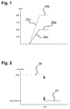
- the course of the rail pressure before starting in Fig. 1 outlined.
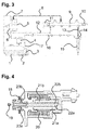
- Fig. 2 are the position of the metering unit 6, dash-dotted lines and the reference numeral 26, and the position of the pressure control valve 11, pulled through and provided with the reference numeral 27, shown for the operation of the internal combustion engine with vegetable oil.
- the metering unit 6 is fully opened. This state of the metering unit is in Fig. 2 represented by the dashed line 26.
- the pressure control valve 11 is controlled during this period via the map. Through the complete opening of the metering unit 6, more fuel can be compressed by the high-pressure pump 5 and the starting pressure in the common rail 9 is reached faster.
- the dashed line 24b which represents the pressure rise in the common rail 9 in the use of vegetable oil fuel, has a greater slope than the solid line 24a, which stands for the pressure increase in the common rail 9 when using diesel fuel.
- the starting pressure 25b for vegetable oil fuel is indeed higher than the starting pressure 25a for diesel fuel, but is reached at about the same time. In this way, when using vegetable oil fuel no longer lead time must be accepted.
- the pressure control valve 11 is set according to the solid line 27 from this limit temperature to the maximum permissible in the common rail 9 maximum pressure. Normally, the control then takes place exclusively via the metering unit 6, as in the case of the use of diesel fuel in a common rail system without a pressure regulating valve. Only with rapid load increase the metering unit 6 is fully opened again and the control is carried out exclusively via the pressure control valve 11.
Abstract
Die Erfindung geht aus von einer direkteinspritzenden selbstzündenden Brennkraftmaschine, die mit einem Kraftstoff mit niedrigem Zündpunkt und mit einem Kraftstoff mit höherem Zündpunkt betreibbar ist, mit wenigstens einem Injektor (15) zum Einspritzen von Kraftstoff, einem Hochdruckspeicher (9) für den Kraftstoff, einer Hochdruckpumpe (5) und einer Zumesseinheit (6) und mit einer elektronischen Steuerung, in der unterschiedliche Steuerungsparameter für den Betrieb mit dem Kraftstoff mit niedrigem Zündpunkt und dem Betrieb mit dem Kraftstoff mit höherem Zündpunkt hinterlegt sind. Erfindungsgemäß ist in der elektronischen Steuerung der Startdruck (25) hinterlegt, der in dem Hochdruckspeicher (9) erreicht werden muss, damit die Startfreigabe erfolgt, wobei der Startdruck (25) für den Kraftstoff mit dem höheren Zündpunkt gegenüber dem Kraftstoff mit dem niedrigen Zündpunkt mehr als 30 % erhöht ist.The invention is based on a direct injection auto-ignition internal combustion engine which is operable with a low ignition point fuel and a higher ignition point fuel, with at least one injector (15) for injecting fuel, a high pressure accumulator (9) for the fuel, a high pressure pump (5) and a metering unit (6) and with an electronic control in which different control parameters for the operation with the low ignition fuel and the operation with the fuel with higher ignition point are stored. According to the invention in the electronic control of the starting pressure (25) deposited, which must be achieved in the high-pressure accumulator (9), so that the start release, wherein the starting pressure (25) for the fuel with the higher ignition point over the fuel with the low ignition point more than 30% is increased.
Description
Die Erfindung betrifft eine direkteinspritzende selbstzündende Brennkraftmaschine nach dem Oberbegriff von Anspruch 1.The invention relates to a direct-injection self-igniting internal combustion engine according to the preamble of claim 1.
Aufgrund der Verknappung von Erdöl und aus Gründen des Umweltschutzes sind Motoren bekannt geworden, die mit Pflanzenöl oder anderen aus Pflanzenöl gewonnenen Kraftstoffen betrieben werden können. Die alten Vor- und Wirbelkammermotoren konnten so abgeändert werden, dass sie im so genannten Ein-Tank-System für den Betrieb mit Pflanzenöl geeignet waren. Diese Motoren konnten nach der Anpassung auf den Pflanzenölbetrieb jedoch weiterhin auch mit Dieselkraftstoff betrieben werden.Due to the shortage of petroleum and environmental reasons, engines have become known which can be operated with vegetable oil or other fuels derived from vegetable oil. The old vortex and vortex chamber motors could be modified so that they were suitable in the so-called single-tank system for operation with vegetable oil. However, these engines could continue to be operated with diesel fuel after adaptation to vegetable oil operations.
Bei den direkteinspritzenden Dieselmotoren, die insbesondere mit Common-Rail-Technik arbeiten, sind die Parameter für die Motorsteuerung so auf einen einzigen Kraftstoff optimiert, dass ein Betrieb mit einem alternativen Kraftstoff praktisch nicht mehr möglich ist. Dies ist zurückzuführen auf die doch sehr unterschiedlichen Eigenschaften von Pflanzenöl und Dieselkraftstoff. Während Dieselkraftstoff beispielsweise über einen beachtlichen Temperaturbereich keine Viskositätsänderung zeigt, ist Pflanzenöl bei tieferen Temperaturen doch sehr zähflüssig. Weiterhin handelt es sich bei Pflanzenöl um einen Kraftstoff, dessen Zündpunkt erheblich höher liegt als der Zündpunkt von Dieselkraftstoff.In direct injection diesel engines, which operate in particular with common rail technology, the parameters for the engine control are optimized for a single fuel that operation with an alternative fuel is practically no longer possible. This is due to the very different properties of vegetable oil and diesel fuel. For example, while diesel fuel does not show a change in viscosity over a considerable temperature range, vegetable oil is very viscous at lower temperatures. Furthermore, vegetable oil is a fuel whose ignition point is significantly higher than the ignition point of diesel fuel.
Das bedeutet, dass bei Pflanzenöl diejenige Temperatur, auf die man das Pflanzenöl erhitzen muss, damit es sich in Gegenwart von Luftsauerstoff ohne Zündquelle, ausschließlich aufgrund seiner Erhitzung, selbst entzündet, wesentlich höher liegt als bei Dieselkraftstoff. Der Zündpunkt von Dieselkraftstoff liegt bei ca. 220°C, während der Zündpunkt von Pflanzenöl - abhängig von der Sorte - bei etwa 300°C liegt.This means that with vegetable oil the temperature at which the vegetable oil must be heated so that it ignites spontaneously in the presence of atmospheric oxygen without an ignition source, solely because of its heating, is much higher than with diesel fuel. The ignition point of diesel fuel is about 220 ° C, while the ignition point of vegetable oil - depending on the variety - is about 300 ° C.
Diese Unterschiede führen dazu, dass bei modernen Motoren, die auf Leistung und Abgasverhalten optimiert sind, bei Verwendung dieser unterschiedlichen Treibstoffe auch mit unterschiedlichen Motorsteuerungsparametern operiert werden muss. Dies würde bedeuten, dass ein Motor, der einmal an den Betrieb mit Pflanzenöl angepasst ist, nicht mehr mit Dieselkraftstoff zu betreiben ist. Da europaweit jedoch keine flächendeckende Versorgung mit Pflanzenöl gewährleistet ist, würde dies einen enormen Komfortverlust bedeuten. Die weitere Marktdurchsetzung mit Pflanzenölmotoren wäre daher stark in Frage gestellt.These differences mean that, with modern engines that are optimized for performance and exhaust performance, using these different fuels also requires different engine control parameters. This would mean that an engine once adapted for operation with vegetable oil can no longer be run on diesel fuel. However, since no nationwide supply of vegetable oil is guaranteed throughout Europe, this would mean a huge loss of comfort. The further market penetration with vegetable oil engines would therefore be strongly questioned.
Gerade im landwirtschaftlichen Bereich ist es aber auch heute noch nicht abschätzbar, wie sich der Preis für Pflanzenöl zukünftig entwickeln wird. Da landwirtschaftliche Maschinen aber in den meisten Fällen auf eine sehr lange Lebensdauer ausgelegt sind, wäre in diesem Bereich eine ausschließlich mit Pflanzenöl betreibbare Maschine nicht in größeren Stückzahlen verkaufbar.Even in the agricultural sector, it is still not possible to predict how the price of vegetable oil will develop in the future. Since agricultural machines are designed in most cases to have a very long service life, a machine that can only be operated with vegetable oil would not be able to be sold in large quantities in this area.
Es hat sich herausgestellt, dass es bei modernen selbstzündenden Brennkraftmaschinen, beispielsweise bei Brennkraftmaschinen mit Common-Rail-Technik, zu Startschwierigkeiten kommen kann, wenn die Temperatur im Winter stark abfällt. Dies gilt ganz besonders, wenn alternative Kraftstoffe wie Pflanzenöl oder entsprechende Gemische mit hohem Zündpunkt und hoher Viskosität bei niedrigen Temperaturen verwendet werden. Bei dieser Problematik kann aber auch die Verschiebung des Einspritzzeitpunkts nur bedingt helfen.It has been found that in modern self-igniting internal combustion engines, for example in internal combustion engines with common rail technology, start-up problems can occur when the temperature drops sharply in winter. This is especially true when using alternative fuels such as vegetable oil or similar high-ignition and high-viscosity blends at low temperatures. In this problem, but also the shift of the injection timing can help only conditionally.
Es wurde bereits versucht, den Kraftstoff vor der Einspritzung über Wärmetauscher aus dem Kühlkreislauf des Motors zu erwärmen. Diese Maßnahme hat sich zwar nach dem Start als wirkungsvoll erwiesen, konnte die Startprobleme aber nicht mindern, da für die Startphase noch kein angewärmter Kraftstoff zur Verfügung steht.Attempts have been made to heat the fuel through the heat exchanger from the engine's cooling circuit prior to injection. Although this measure has proven to be effective after takeoff, it was unable to reduce the startup problems, as no warmed up fuel is available for the launch phase.
Es wurde auch bereits versucht, den Kraftstoff elektrisch vorzuheizen, indem die Kraftstoffleitung vor der Hochdruckpumpe mit einer elektrischen Heizmanschette umwickelt wurde. Auf diese Weise konnten Erfolge bei der Startfähigkeit erzielt werden, es hat sich jedoch herausgestellt, dass sehr lange Vorheizzeiten benötigt werden und die Batterie damit sehr stark belastet wird.It has also been tried to electrically pre-heat the fuel by the fuel line was wrapped in front of the high-pressure pump with an electric heating cuff. In this way, success was achieved in the startability, but it has been found that very long preheating times are needed and the battery is very heavily loaded.
Auch andere Heiz-Lösungen werden oftmals als zu umständlich und zu teuer angesehen und aus diesen Gründen abgelehnt.Other heating solutions are often considered too cumbersome and too expensive and rejected for these reasons.
Der Erfindung liegt die Aufgabe zugrunde, eine direkteinspritzende selbstzündende Brennkraftmaschine so weiterzubilden, dass sie sowohl mit einem Kraftstoff mit niedrigem Zündpunkt - insbesondere Pflanzenöl oder einem aus Pflanzenöl gewonnenen Kraftstoff-als auch mit Dieselkraftstoff betrieben werden kann und mit beiden Kraftstoffen ohne aufwändige Maßnahmen auch bei tiefen Temperaturen gestartet werden kann.The invention has the object of developing a direct injection auto-ignition internal combustion engine so that it can be operated both with a fuel with low ignition point - especially vegetable oil or a fuel oil derived from vegetable oil and diesel fuel and with both fuels without complex measures even at low Temperatures can be started.
Gelöst wird die Aufgabe gemäß der Erfindung durch eine direkteinspritzende selbstzündende Brennkraftmaschine mit den Merkmalen von Anspruch 1. Erfindungsgemäß ist in der elektronischen Steuerung der Startdruck hinterlegt ist, der in dem Hochdruckspeicher erreicht werden muss, damit die Startfreigabe erfolgt, wobei der Startdruck für den Kraftstoff mit dem höheren Zündpunkt gegenüber dem Kraftstoff mit dem niedrigen Zündpunkt mehr als 30 % insbesondere mehr als 50 % erhöht ist.The object is achieved according to the invention by a direct-injection self-igniting internal combustion engine with the features of claim 1. According to the invention, the starting pressure is stored in the electronic control, which must be achieved in the high-pressure accumulator so that the start release takes place, the starting pressure for the fuel the higher ignition point is increased over the fuel with the low ignition point more than 30%, in particular more than 50%.
Es wurde herausgefunden, dass für die Startproblematik bei dem Betrieb mit Kraftstoffen mit höherem Zündpunkt oftmals ein Filter- und Dämpfelement mit verantwortlich ist, das zwischen dem Hochdruckspeicher und dem Injektor in die Kraftstoffleitung eingesetzt ist. In vielen Fällen befindet sich dieses Filter- und Dämpfelement auch in dem so genannten Druckrohrstutzen direkt am Injektor. Das Filter- und Dämpfelement hat normalerweise hauptsächlich die Aufgabe, zu verhindern, dass von dem Kraftstoff mitgerissene Partikel, wie beispielsweise Späne, die bei der Montage entstehen können, der Brennkraftmaschine zugeführt werden und so zu Beschädigungen führen können.It has been found that the starter problem in operating with higher ignition fuel is often due to a filter and damper element inserted between the high pressure accumulator and the injector in the fuel line. In many cases, this filter and damping element is also located in the so-called pressure pipe socket directly on the injector. The filter and damping element normally has the main task of preventing particles entrained by the fuel, such as chips, which may arise during assembly, from being fed to the internal combustion engine and thus leading to damage.
Das Filter- und Dämpfelement hat aber ebenso die Wirkung, Schwingungen in der Kraftstoffleitung zwischen dem Hochdruckspeicher und dem Injektor zu verhindern. Solche Schwingungen können durch das Öffnen und Schließen des Injektors entstehen und dazu führen, dass während der Einspritzung an den Einspritzöffnungen des Injektors ein schwankender Druck ansteht, was zu Ungenauigkeiten in der Einspritzung führen kann. Durch das Filter- und Dämpfelement wird das Entstehen solcher Schwingungen verhindert.But the filter and damping element also has the effect of preventing vibrations in the fuel line between the high-pressure accumulator and the injector. Such vibrations may be caused by the opening and closing of the injector and may cause a fluctuating pressure to be applied to the injection openings of the injector during injection, which may result in inaccuracies in the injection. By the filter and damping element, the occurrence of such vibrations is prevented.
Das Filter- und Dämpfelement hat - um seine Aufgaben erfüllen zu können - relativ kleine Durchlässe für den Kraftstoff. Befindet sich in diesem Leitungsabschnitt nun der Kraftstoff mit höherem Zündpunkt, kann es bei niedrigen Temperaturen zu einem eingeschränkten Volumenfluss durch das Filter- und Dämpfelement kommen. Durch die erfindungsgemäße Anhebung des Startdrucks liegt auch an dem Filter- und Dämpfelement beim Start der Brennkraftmaschine ein höherer Kraftstoffdruck an. Der eingeschränkte Volumenfluss kann hierdurch kompensiert werden, ohne dass dabei Nachteile bei der Einspritzung durch den Injektor entstehen.The filter and damping element has - to fulfill its tasks - relatively small passages for the fuel. If the fuel with a higher ignition point is now located in this line section, a restricted volume flow through the filter and damping element can occur at low temperatures. By raising the starting pressure according to the invention, a higher fuel pressure is also applied to the filter and damping element when starting the internal combustion engine. The limited volume flow can be compensated thereby, without causing disadvantages in the injection through the injector.
Im Injektor steht auf diese Weise in etwa der gleiche Kraftstoffdruck zur Einspritzung an, wie bei Verwendung des Kraftstoffs mit niedrigem Zündpunkt. Es lassen sich folglich durch den unterschiedlichen Startdruck für die beiden Kraftstoffarten ähnliche Bedingungen im Injektor erreichen.In the injector is in this way about the same fuel pressure for injection, as when using the fuel with low ignition point. It can therefore be achieved by the different starting pressure for the two types of fuel similar conditions in the injector.
Weitere Einzelheiten und Vorteile der Erfindung ergeben sich aus den Unteransprüchen.Further details and advantages of the invention will become apparent from the dependent claims.
Bei den ersten Common-Rail-Systemen ist die Förderleistung der Hochdruckpumpe so ausgelegt, dass die Versorgung bei Volllast und hoher Drehzahl ausreicht und im Leerlauf bzw. bei Teillast ein Fördermengenüberschuss besteht. Dieser zu viel geförderte Kraftstoff wird über ein Druckregelventil an dem Hochdruckspeicher zum Kraftstofftank zurückgeführt. Nachteilig dabei war ein zu hoher Leistungsbedarf der Hochdruckpumpe und eine zu starke Kraftstofferwärmung im Rücklauf.In the first common-rail systems, the delivery capacity of the high-pressure pump is designed so that the supply at full load and high speed sufficient and at idle or at partial load, there is a flow surplus. This too much subsidized fuel is returned via a pressure control valve on the high-pressure accumulator to the fuel tank. The disadvantage here was too high power consumption of the high pressure pump and excessive fuel heating in the return.
Bei den neueren Common-Rail-Systemen wird der Druck in dem Hochdruckspeicher (Raildruck) niederdruckseitig über ein Mengenregelventil (Zumesseinheit) geregelt. Dabei wird der in die Pumpenelemente strömende Kraftstoff durch das stufenlos regelbares Magnetventil der Zumesseinheit dosiert. Dieses Magnetventil passt die in den Hochdruckspeicher geförderte Kraftstoffmenge dem Systembedarf an. Bei der Ansteuerung des Magnetventils wird ein Kolben durch Magnetkraft betätigt, der entsprechend seiner Stellung, einen unterschiedlichen Zulaufquerschnitt freigibt. Mit dieser Mengenregelung wird der Leistungsbedarf der Hochdruckpumpe gesenkt und sie fördert nur so viel Kraftstoff, dass der momentan erforderliche Druck in dem Hochdruckspeicher (Raildruck) erzeugt werden kann. Die Hochdruckpumpe fördert auf diese Weise nur die Kraftstoffmenge, die der Motor tatsächlich benötigt. Dadurch sinkt der Energiebedarf der Hochdruckpumpe und damit der Kraftstoffverbrauch. Besonders vorteilhaft sind deshalb in der elektronischen Steuerung Parameter zur Steuerung der Zumesseinheit hinterlegt, wobei die Öffnung der Zumesseinheit für den Kraftstoff mit dem höheren Zündpunkt für den Startvorgang gegenüber dem Kraftstoff mit dem niedrigen Zündpunkt mehr als 20 % vergrößert ist. Durch diese Maßnahme lässt sich der erhöhte Startdruck in dem Hochdruckspeicher für den Kraftstoff mit höherem Zündpunkt schneller erreichen.In the newer common-rail systems, the pressure in the high-pressure accumulator (rail pressure) is regulated on the low-pressure side via a flow control valve (metering unit). In this case, the fuel flowing into the pump elements is metered by the continuously variable solenoid valve of the metering unit. This solenoid valve adjusts the amount of fuel delivered to the high-pressure accumulator according to the system requirements. When driving the solenoid valve, a piston is actuated by magnetic force, which releases according to its position, a different inlet cross-section. With this flow control, the power requirement of the high pressure pump is lowered and it promotes only so much fuel that the currently required pressure in the high-pressure accumulator (rail pressure) can be generated. The high-pressure pump in this way promotes only the amount of fuel that the engine actually needed. This reduces the energy requirement of the high pressure pump and thus the fuel consumption. Therefore, particularly advantageous parameters for controlling the metering unit are stored in the electronic control system, wherein the opening of the metering unit for the fuel with the higher ignition point for the starting process is increased by more than 20% compared with the fuel with the low ignition point. By this measure, the increased starting pressure in the high-pressure accumulator for the fuel with higher ignition point can be achieved faster.
Besonder vorteilhaft bewirken die in der elektronischen Steuerung hinterlegten Parameter für den Betrieb der Brennkraftmaschine mit dem Kraftstoff mit dem höheren Zündpunkt beim Starten der Brennkraftmaschine eine vollständige Öffnung der Zumesseinheit. Hierdurch lässt sich das Erreichen des Startdrucks am meisten beschleunigen.Particularly advantageous effect the stored in the electronic control parameters for the operation of the internal combustion engine with the fuel with the higher ignition point when starting the internal combustion engine, a complete opening of the metering unit. This can accelerate the achievement of the starting pressure the most.
Bei Common-Rail-Systemen, bei denen der Druck nur auf der Saugseite mit der Zumesseinheit eingestellt werden kann, hat sich gezeigt, dass der Druckaufbau bzw. der Druckabbau im Hochdruckspeicher bei schnellen Lastwechseln oftmals zu lange dauert weil die Druckanpassung an die veränderten Lastbedingungen zu träge reagiert. Deshalb werden bei den neuesten Common-Rail-Systemen, die auch oftmals mit Piezo-Inline-Injektoren ausgerüstet sind, zur Druckregelung zwei Drucksteller eingesetzt. Diese Common-Rail-Systeme enthalten neben der Zumesseinheit an der Hochdruckpumpe zusätzlich ein Druckregelventil an dem Hochdruckspeicher. Hierdurch werden die Vorteile der niederdruckseitigen Regelung mit der schnellen hochdruckseitigen Regelung kombiniert. Besonders vorteilhaft ist deshalb an dem Hochdruckspeicher ein über die elektronische Steuerung ansteuerbares Druckregelventil vorgesehen, wobei die in der elektronischen Steuerung hinterlegten Parameter für den Betrieb der Brennkraftmaschine mit dem Kraftstoff mit dem höheren Zündpunkt während der Startphase der Brennkraftmaschine eine Regelung des Höchstdruckes in dem Druckspeicher ausschließlich über das Druckregelventil bewirken. Hierdurch wird zwar während des Startvorgangs mit dem Kraftstoff mit höherem Zündpunkt der Energiebedarf minimal erhöht, aber es ergibt sich auch in dem Hochdruckspeicher eine höhere Kraftstofftemperatur, so dass die Viskosität des Kraftstoffs mit höherem Zündpunkt herabgesetzt wird.In common-rail systems, where the pressure can only be adjusted on the suction side with the metering unit, it has been shown that the pressure build-up or the pressure reduction in the high-pressure accumulator often takes too long during rapid load changes because the pressure adjustment to the changed load conditions reacts slowly. That is why the latest common-rail systems, which are often equipped with piezo inline injectors, use two pressure regulators for pressure control. In addition to the metering unit on the high-pressure pump, these common rail systems additionally contain a pressure regulating valve on the high-pressure accumulator. As a result, the advantages of the low-pressure side control combined with the fast high-pressure side control. Particularly advantageous is therefore provided on the high-pressure accumulator via the electronic control controllable pressure control valve, wherein the stored in the electronic control parameters for the operation of the internal combustion engine with the fuel with the higher ignition point during the starting phase of the engine control of the maximum pressure in the accumulator exclusively via effect the pressure control valve. As a result, while the energy requirement is minimally increased during the startup process with the fuel with higher ignition point, but also results in the high-pressure accumulator a higher fuel temperature, so that the viscosity of the fuel is lowered with higher ignition point.
Üblicherweise besitzen Kraftstoffe mit höherem Zündpunkt bei tiefen Temperaturen eine hohe Viskosität. Dagegen ist beispielsweise die Viskosität bei den meisten Sorten von Pflanzenölkraftstoffen und bei Dieselkraftstoff bei höheren Temperaturen nahezu identisch. Eine Ansteuerung von Komponenten des Kraftstoffzuführsystems mit unterschiedlichen Parametern bei der Verwendung von Kraftstoff mit hohem Zündpunkt ist aus diesem Grund normalerweise nur bei tieferen Temperaturen notwendig. Es ist deshalb vorteilhaft eine Grenztemperatur festgelegt, oberhalb der die Steuerungsparameter für den Startdruck und/oder die Regelung der Zumesseinheit während der Startphase und/oder die Regelung des Druckregelventils während der Startphase für beide Kraftstoffe identisch sind.Usually fuels with higher ignition point at low temperatures have a high viscosity. By contrast, for example, the viscosity is almost identical for most grades of vegetable oil fuels and diesel at higher temperatures. For this reason, activation of components of the fuel supply system with different parameters when using high-ignition fuel is normally only necessary at lower temperatures. It is therefore advantageous to set a limit temperature above which the control parameters for the starting pressure and / or the regulation of the metering unit during the starting phase and / or the regulation of the pressure regulating valve during the starting phase are identical for both fuels.
Die meisten Pflanzenölkraftstoffe verhalten sich bezüglich ihrer Viskosität oberhalb einer bestimmten Temperatur ähnlich wie Dieselkraftstoff. Dies gilt sogar für Kraftstoffe auf Basis hochviskoser Pflanzenöle. Vorteilhaft ist deshalb die Grenztemperatur auf eine Temperatur - abhängig von dem verwendeten Kraftstoff mit hohem Zündpunkt - in dem Bereich zwischen 25 und 50°C festgelegt.Most vegetable oil fuels behave like a diesel fuel in viscosity above a certain temperature. This even applies to fuels based on highly viscous vegetable oils. Advantageously, therefore, the limit temperature to a temperature - depending on the fuel used with a high ignition point - set in the range between 25 and 50 ° C.
Pflanzenöle, die sehr häufig die Basis für Kraftstoffe bilden, sind beispielsweise Rapsoder Sonnenblumenöl. Solche Kraftstoffe verhalten sich bereits bei einer Temperatur von 30°C hinsichtlich ihrer Viskosität ähnlich wie Dieselkraftstoff. Es ist deshalb besonders vorteilhaft die Grenztemperatur auf 30°C festgelegt.Vegetable oils, which very often form the basis for fuels, are, for example, rapeseed or sunflower oil. Such fuels behave at a temperature of 30 ° C in terms of their viscosity similar to diesel fuel. It is therefore particularly advantageous to set the limit temperature to 30 ° C.
Die Problematik bei Kraftstoffen mit höherem Zündpunkt wird zumindest zum Teil durch die höhere Viskosität bei tiefen Temperaturen hervorgerufen. Die Viskosität des verwendeten Kraftstoffes kann über seine Temperatur ermittelt werden. Andererseits wird bei Serien-Brennkraftmaschinen die Temperatur des Kraftstoffes üblicherweise an anderen, nicht relevanten Stellen gemessen. Es müsste folglich ein zusätzlicher Temperatursensor im Kraftstoffkreislauf vorgesehen werden. Um solche zusätzliche Hardware zu vermeiden, ist es sinnvoll eine andere Temperatur zu verwenden, die aber einen Rückschluss auf die Kraftstofftemperatur zulässt. Vorteilhaft wird die Grenztemperatur deshalb auf die Temperatur des Kühlmittels angewandt. Dabei kann der übliche Temperaturfühler im Kühlwasserkreislauf der Brennkraftmaschine verwendet werden und es wird nicht der Einbau zusätzlicher Hardware notwendig.The problem with fuels with higher ignition point is caused at least in part by the higher viscosity at low temperatures. The viscosity of the fuel used can be determined by its temperature. On the other hand, in series internal combustion engines, the temperature of the fuel is usually measured at other, non-relevant points. It would therefore be necessary to provide an additional temperature sensor in the fuel circuit. To avoid such additional hardware, it makes sense to use a different temperature, but allows a conclusion on the fuel temperature. Advantageously, the limit temperature is therefore applied to the temperature of the coolant. In this case, the usual temperature sensor can be used in the cooling water circuit of the internal combustion engine and it is not the installation of additional hardware necessary.
Um die Komponenten der Kraftstoffzuführung in Abhängigkeit des verwendeten Treibstoffs mit unterschiedlichen Parametern ansteuern zu können, muss bekannt sein welcher Treibstoff verwendet wird. Diese Festlegung kann beispielsweise durch den Nutzer vorgenommen werden. Hierzu muss nach einer Betankung eine Eingabe erfolgen, über die der Motorsteuerung die Art des Kraftstoffs mitgeteilt wird. Hierzu ist eine Schnittstelle notwendig, über die der Nutzer die Eingabe vornehmen kann. Besonders vorteilhaft ist aber ein Sensor vorgesehen, der die Art des verwendeten Kraftstoffs detektiert. Auf diese Weise ist keine Fehleingabe durch den Nutzer möglich und Wahrscheinlichkeit einer falschen Ansteuerung lässt sich stark herabsetzen.In order to control the components of the fuel supply in dependence of the fuel used with different parameters, it must be known which fuel is used. This determination can be made, for example, by the user. For this purpose, after refueling, an input must be made via which the type of fuel is communicated to the engine control. For this purpose, an interface is necessary, via which the user can make the input. But a sensor is particularly advantageous, which detects the type of fuel used. In this way, no erroneous input by the user is possible and probability of incorrect control can be greatly reduced.
Ein Sensor zum Detektieren des verwendeten Kraftstoffs sollte möglichst nahe an den Komponenten verbaut werden, die - in Abhängigkeit von dem verwendeten Kraftstoff - unterschiedlich angesteuert werden sollen. Allerdings sollte bei so einer Bestückung des Kraftstoffleitsystems der unter Hochdruck stehende Teil gemieden werden, da solche zusätzlich eingebauten Komponenten immer Ursache von Leckagen sein können. Der Sensor ist deshalb vorteilhaft im Kraftstoffleitsystem direkt vor der Hochdruckpumpe montiert. Auf diese Weise ist der Sensor direkt vor der ersten unterschiedlich anzusteuernden Komponente montiert und detektiert die Kraftstoffart, die vor dieser Komponente ansteht. Da in diesem Teil des Kraftstoffleitsystems keine hohen Drücke vorherrschen, ist der Einbau problemlos zu bewerkstelligen.A sensor for detecting the fuel used should be installed as close as possible to the components, which should be controlled differently depending on the fuel used. However, in such an assembly of the fuel control system, the part under high pressure should be avoided, since such additionally installed components can always be the cause of leaks. The sensor is therefore advantageous in the fuel supply system mounted directly in front of the high pressure pump. In this way, the sensor is mounted directly in front of the first component to be controlled differently and detects the fuel that is present in front of this component. Since no high pressures prevail in this part of the fuel supply system, the installation is easy to accomplish.
Weitere Einzelheiten und Vorteile der Erfindung ergeben sich aus der Beschreibung eines Ausführungsbeispiels, das anhand der Zeichnung eingehend erläutert wird.Further details and advantages of the invention will become apparent from the description of an embodiment which is explained in detail with reference to the drawing.
Es zeigt:
- Fig. 1
- eine schematische Ansicht der Druckentwicklung im Common-Rail einer erfindungsgemäßen Brennkraftmaschine bei verschiedenen Kraftstoffen,
- Fig. 2
- die Stellung von Zumesseinheit und Druckregelventil in Abhängigkeit von der Temperatur bei einer erfindungsgemäßen Brennkraftmaschine mit Zweisteller-Regelung,
- Fig. 3
- den schematischen Aufbau eines Kraftstoffkreislaufs einer erfindungsgemäßen Brennkraftmaschine und
- Fig. 4
- den Schnitt durch eine Zumesseinheit.
- Fig. 1
- a schematic view of the pressure development in the common rail of an internal combustion engine according to the invention in various fuels,
- Fig. 2
- the position of metering unit and pressure control valve as a function of the temperature in an internal combustion engine according to the invention with two-position control,
- Fig. 3
- the schematic structure of a fuel circuit of an internal combustion engine according to the invention and
- Fig. 4
- the section through a metering unit.
Der in
Weiterhin gehören zu dem gezeigten Common-Rail-System die Zumesseinheit 6 die direkt an der Hochdruckpumpe 5 angebracht ist und das Druckregelventil 11. Durch das Vorhandensein von Zumesseinheit 6 und Druckregelventil 11 spricht man hier von einem so genannten Zweistellersystem. Zur Ansteuerung des Druckregelventils 11 wird noch der Raildrucksensor 10 benötigt, der genauso wie das Druckregelventil 11 mit der Motorsteuerung verbunden ist.Furthermore, belonging to the common-rail system shown, the
Zu dem Kraftstoffkreislauf gehört noch der Kraftstofftank 1, der den Kraftstoff bevorratet. Der Kraftstoff wird von der Kraftstoffpumpe 3 über den Vorfilter 2 entnommen und über die Kraftstoffzuführleitung 17 der Zumesseinheit 6 zugeführt. In die Kraftstoffzuführleitung 17 ist noch der Feinfilter 4 eingebaut, der den Kraftstoff auch von feinsten Partikeln befreit. Der Feinfilter 4 ist so aufgebaut, dass auch evtl. in dem Kraftstoff enthaltenes Wasser abgeschieden werden kann.To the fuel circuit still belongs the fuel tank 1, which stocks the fuel. The fuel is taken from the
In der Hochdruckpumpe 5 wird der von der Zumesseinheit 6 erhaltene Kraftstoff unter Druck gesetzt und über die Hochdruckleitung 8 (alle unter Hochdruck stehenden Leitungen sind schwarz eingezeichnet) dem Comon-Rail 9 zugeführt. Der unter Hochdruck stehende Kraftstoff steht mit dem Raildruck über die Hochdruckleitung 13 auch im Injektor 15 an.In the high-
Zwischen der Hochdruckleitung 13 und dem Injektor 15 befindet sich bei dieser Ausführungsform der Druckrohrstutzen 14. Das Filter- und Dämpfelement in dem Druckrohrstutzen ist in dieser Darstellung nicht sichtbar.Between the high-pressure line 13 and the
Weiterhin weist der Kraftstoffkreislauf noch verschiedene Rückführleitungen auf, die Leckagekraftstoff an verschiedenen Stellen dem System wieder zuführen. So führt die Leckageleitung 7 zu viel zu der Hochdruckpumpe 5 geförderten Kraftstoff in den Kraftstofftank 1 zurück. In dieser Leckageleitung 7 befindet sich zum Teil Kraftstoff, der im Hochdruckteil der Hochdruckpumpe 5 durch tatsächliche Leckagen anfällt. Die leitung führt aber auch überflüssigen Kraftstoff, der von der Kraftstoffpumpe 5 zu viel gefördert wurde. Die Kraftstoffpumpe 5 ist so ausgelegt, dass immer zu viel Kraftstoff gefördert wird. Da in der Kraftstoffpumpe 5 sehr hohe Temperaturen entstehen, wird dieser zu viel geförderte Kraftstoff zur Kühlung der Hochdruckpumpe verwendet. Die Leckageleitung 7 mündet deshalb in den Kraftstofftank 1 der gleichzeitig als Kraftstoffkühler wirkt und dem sich der rückgeführte heiße Kraftstoff mit dem kühlen Kraftstoffvorrat vermischen kann.Furthermore, the fuel circuit still has various return lines that supply leakage fuel at various points to the system again. Thus, the leakage line 7 returns too much to the high-
Über die Leckageleitung 12 und das Druckregelventil 11 kann der Raildruck geregelt werden. Das bedeutet, dass auch hier sehr heißer, gerade eben durch die Hochdruckpumpe auf Hochdruck verdichteter Kraftstoff rückgeführt wird. Die Leckageleitung 12 mündet deshalb ebenso im Kraftstofftank 1. Die Leckageleitung 16 dagegen, die den Leckagekraftstoff aus den Injektoren 15 aufnimmt, mündet in die Kraftstoffzuführleitung 17, die zur Zumesseinheit 6 führt.About the
In
Der Kraftstoffzulauf 18 zu der Zumesseinheit erfolgt über die Kraftstoffzuführleitung 17 (
Die Ansteuerung der Zumesseinheit erfolgt über die Motorsteuerung mit Hilfe eines pulsweitenmodulierten Signals. Bei der Ansteuerung der Magnetspule 20 wird der Stößel 22 mit dem durch die Magnetkraft betätigten Anker 21 bewegt. Über den Stößel 22 wird der Kolben 23 verschoben. Der Kolben 23 wird von einer Feder gegen den Stößel 22 gedrückt. Der Kolben 23 gibt, regelt entsprechend seiner Stellung, den Kraftstoffzulauf 18.The control of the metering unit via the motor control by means of a pulse width modulated signal. When driving the
Bei älteren Common-Rail-Systemen war die Förderleistung der Hochdruckpumpe so ausgelegt, dass die Versorgung bei Volllast und hoher Drehzahl ausreicht und im Leerlauf bzw. Teillast ein Fördermengenüberschuss besteht. Dieser zu viel verdichtete Kraftstoff wurde über das Druckregelventil an dem Common-Rail zum Kraftstoffbehälter zurückgeführt. Hierdurch ergab sich jedoch ein sehr hoher Leistungsbedarf der Hochdruckpumpe.In older common-rail systems, the delivery capacity of the high-pressure pump was designed so that the supply at full load and high speed sufficient and at idle or partial load there is a flow surplus. This too much compressed fuel was returned via the pressure control valve on the common rail to the fuel tank. However, this resulted in a very high power requirement of the high-pressure pump.
Bei den folgenden Common-Rail-Systemen wurde der Raildruck niederdruckseitig über ein Mengenregelventil (Zumesseinheit) geregelt. Die Hochdruckpumpe fördert dadurch nur die Kraftstoffmenge, die der Motor tatsächlich benötigt. Durch diese Ausführung sinkt der Energiebedarf der Hochdruckpumpe, und damit der Kraftstoffverbrauch.In the following common-rail systems, the rail pressure was regulated on the low-pressure side via a flow control valve (metering unit). The high-pressure pump thereby promotes only the amount of fuel that the engine actually needs. Through this design, the energy consumption of the high-pressure pump, and thus the fuel consumption decreases.
Bei den Hochdruckpumpen in diesen Common-Rail-Systemen ist eine Verbesserung des Wirkungsgrades durch eine kraftstoffzulaufseitige (saugseitige) Mengenregelung erreicht worden. Hierbei wird der in die Pumpenelemente strömende Kraftstoff durch die stufenlos regelbare Zumesseinheit dosiert. Dieses Mengenregelventil ist ist bei diesen Common-Rail-Systemen anstatt des Druckregelventils des Common-Rails an die Hochdruckpumpe angebaut worden und passte die ins Common-Rail geförderte Kraftstoffmenge dem Systembedarf an. Die Zumesseinheit fördert nur so viel Kraftstoff, dass der aus einem Kennfeld verlangte Raildruck erzeugt werden kann.In the high-pressure pumps in these common-rail systems, an improvement in the efficiency has been achieved by a fuel inlet side (suction) flow control. In this case, the fuel flowing into the pump elements is metered by the continuously variable metering unit. This quantity control valve has been attached to the high-pressure pump instead of the pressure control valve of the common rail in these common-rail systems and adapted the volume of fuel delivered to the common rail to the system requirement. The metering unit only delivers so much fuel that the rail pressure required from a map can be generated.
Es hat sich jedoch gezeigt, dass bei schnellen Lastwechseln der Druckaufbau bzw. der Druckabbau im Common-Rail zu lange dauert, wenn der Druck nur auf der Saugseite mit der Zumesseinheit eingestellt werden kann. Die Druckanpassung an die veränderten Lastbedingungen reagiert zu träge. Deshalb erhielten neueste Common-Rail-Systeme neben der Zumesseinheit 6 an der Hochdruckpumpe 5 zusätzlich wieder das Druckregelventil 11 am Common-Rail 9. Mit diesem Zweistellersystem werden die Vorteile der niederdruckseitigen Regelung mit der schnellen hochdruckseitigen Regelung kombiniert.However, it has been shown that with rapid load changes the pressure build-up or the pressure reduction in the common rail takes too long, if the pressure can be adjusted only on the suction side with the metering unit. The pressure adjustment to the changed load conditions reacts too slowly. Therefore, the latest common-rail systems in addition to the
Um die Brennkraftmaschine beispielsweise mit Dieselkraftstoff und mit Pflanzenölkraftstoff betreiben zu können, muss das Common-Rail-System - insbesondere bei Kaltstart-Bedingungen - unterschiedlich angesteuert werden. Für ein besonders vorteilhaftes Zweistellersystem ist der Verlauf des Raildrucks vor dem Start in
Der Verlauf des Raildrucks mit Dieselkraftstoff ist durchgezogen dargestellt und jeweils mit dem Buchstaben a gekennzeichnet, während der Verlauf des Raildrucks mit Pflanzenöl gestrichelt dargestellt und jeweils mit dem Buchstaben b bezeichnet ist.The course of the rail pressure with diesel fuel is shown in solid lines and each marked with the letter a, while the course of the rail pressure with vegetable oil shown in dashed lines and each with the letter b is designated.
In
Bei einem Start mit Dieselkraftstoff wird die Zumesseinheit 6 entsprechend dem Kennfeld geöffnet. Gleiches gilt für das Druckregelventil 11.When starting with diesel
Bei einem Start mit Pflanzenölkraftstoff wird die Zumesseinheit 6 dagegen vollständig geöffnet. Dieser Zustand der Zumesseinheit ist in
Dies ist gut aus
Bei dem Diagramm nach
Das Druckregelventil 11 wird entsprechend der durchgezogenen Linie 27 ab dieser Grenztemperatur auf den maximal im Common-Rail 9 zulässigen Höchstdruck eingestellt. Im Normalfall findet die Regelung dann wie bei der Verwendung von Dieselkraftstoff in einem Common-Rail-System ohne Druckregelventil ausschließlich über die Zumesseinheit 6 statt. Nur bei schneller Lastzunahme wird die Zumesseinheit 6 wieder vollständig geöffnet und die Regelung wird ausschließlich über das Druckregelventil 11 vorgenommen.The
- 11
- KraftstofftankFuel tank
- 22
- Vorfilterprefilter
- 33
- KraftstoffpumpeFuel pump
- 44
- Feinfilter mit WasserabscheiderFine filter with water separator
- 55
- Hochdruckpumpehigh pressure pump
- 66
- Zumesseinheit (Mengenregelventil)Metering unit (flow control valve)
- 77
- Leckageleitung zum KraftstofftankLeakage line to the fuel tank
- 88th
- Hochdruckleitung zum Common RailHigh pressure line to common rail
- 99
- Common Rail (Druckspeicher)Common Rail (pressure accumulator)
- 1010
- RaildrucksensorRail pressure sensor
- 1111
- DruckregelventilPressure control valve
- 1212
- Leckageleitung vom Common RailLeakage line from Common Rail
- 1313
- Hochdruckleitung zum InjektorHigh pressure line to the injector
- 1414
- DruckrohrstutzenAn inlet connector
- 1515
- Injektorinjector
- 1616
- Leckageleitung vom InjektorLeakage line from the injector
- 1717
- Kraftstoffzuführleitungfuel supply
- 1818
- Kraftstoffzulauf zur ZumesseinheitFuel supply to the metering unit
- 1919
- Kraftstoffablauf zur HochdruckpumpeFuel outlet to the high pressure pump
- 2020
- Magnetspulesolenoid
- 2121
- Ankeranchor
- 2222
- Stößeltappet
- 2323
- Kolbenpiston
- 2424
- Druckanstieg vor StartfreigabePressure increase before start release
- 2525
- Startdruckstarting pressure
- 2626
- Stellung der ZumesseinheitPosition of the metering unit
- 2727
- Stellung des DruckregelventilsPosition of the pressure control valve
Claims (10)
Applications Claiming Priority (1)
| Application Number | Priority Date | Filing Date | Title |
|---|---|---|---|
| AT4562015 | 2015-07-10 |
Publications (1)
| Publication Number | Publication Date |
|---|---|
| EP3115584A1 true EP3115584A1 (en) | 2017-01-11 |
Family
ID=56360248
Family Applications (1)
| Application Number | Title | Priority Date | Filing Date |
|---|---|---|---|
| EP16177925.1A Withdrawn EP3115584A1 (en) | 2015-07-10 | 2016-07-05 | Direct injection combustion engine of self-ignition type |
Country Status (1)
| Country | Link |
|---|---|
| EP (1) | EP3115584A1 (en) |
Citations (6)
| Publication number | Priority date | Publication date | Assignee | Title |
|---|---|---|---|---|
| US5190001A (en) * | 1990-08-22 | 1993-03-02 | Volkswagen Ag | Fuel supply system for an engine operating an alcohol-containing fuel |
| US20100071661A1 (en) * | 2007-06-06 | 2010-03-25 | Robert Bosch Gmbh | Method for fuel injection |
| DE102009023047A1 (en) * | 2009-05-28 | 2010-12-02 | Alois Dotzer | Diesel engine operated internal combustion engine |
| US20120318237A1 (en) * | 2010-03-08 | 2012-12-20 | Toyota Jidosha Kabushiki Kaisha | Fuel injection apparatus for internal combustion engine |
| US20130275029A1 (en) * | 2012-03-26 | 2013-10-17 | Robert Bosch Gmbh | Method and control unit for starting an otto engine |
| US20140299103A1 (en) * | 2013-04-09 | 2014-10-09 | Denso Corporation | Fuel injection control device for internal combustion engine |
-
2016
- 2016-07-05 EP EP16177925.1A patent/EP3115584A1/en not_active Withdrawn
Patent Citations (6)
| Publication number | Priority date | Publication date | Assignee | Title |
|---|---|---|---|---|
| US5190001A (en) * | 1990-08-22 | 1993-03-02 | Volkswagen Ag | Fuel supply system for an engine operating an alcohol-containing fuel |
| US20100071661A1 (en) * | 2007-06-06 | 2010-03-25 | Robert Bosch Gmbh | Method for fuel injection |
| DE102009023047A1 (en) * | 2009-05-28 | 2010-12-02 | Alois Dotzer | Diesel engine operated internal combustion engine |
| US20120318237A1 (en) * | 2010-03-08 | 2012-12-20 | Toyota Jidosha Kabushiki Kaisha | Fuel injection apparatus for internal combustion engine |
| US20130275029A1 (en) * | 2012-03-26 | 2013-10-17 | Robert Bosch Gmbh | Method and control unit for starting an otto engine |
| US20140299103A1 (en) * | 2013-04-09 | 2014-10-09 | Denso Corporation | Fuel injection control device for internal combustion engine |
Similar Documents
| Publication | Publication Date | Title |
|---|---|---|
| DE19742180C2 (en) | Injection system for an internal combustion engine and method for regulating an injection system | |
| DE102013213506B4 (en) | Method for operating a fuel injection system with a fuel filter heater and fuel injection system | |
| EP2098707B1 (en) | Internal combustion engine operated as a Diesel engine | |
| DE102008001240A1 (en) | Method and device for controlling a fuel supply system | |
| DE10061987A1 (en) | Method and device for cooling a fuel injection system | |
| EP2601396B1 (en) | Internal combustion engine with liquid and gaseous fuel | |
| EP2080888B1 (en) | Automatic fuel detection | |
| EP1348072A1 (en) | Method, computer program and control and/or regulation device for operating an internal combustion engine, and corresponding internal combustion engine | |
| DE102006033141A1 (en) | Metered, high-pressure direct petrol injection into engine, is complemented by controlled single-point injection into inlet manifold, especially during heavy loading and cold starting | |
| EP2643582B1 (en) | Method for operating a fuel system of an internal combustion engine | |
| DE102004002139A1 (en) | Fuel supply system for an internal combustion engine | |
| WO2017140480A1 (en) | Internal combustion engine and method for operating an internal combustion engine | |
| DE102012209747A1 (en) | fuel injection system | |
| EP2098706B1 (en) | Diesel internal combustion engine | |
| EP2014908A1 (en) | Combustion engine that can be operated either with diesel or biogenous fuel | |
| EP3115584A1 (en) | Direct injection combustion engine of self-ignition type | |
| EP1273780A2 (en) | Procedure for operating an internal combustion engine particularly in a motor vehicle | |
| EP1436495B1 (en) | Method, programme and control and/or regulating apparatus for operating a direct injection internal combustion engine | |
| DE102009029596B4 (en) | Method for controlling an internal combustion engine | |
| EP2435683B1 (en) | Apparatus for controlling an internal combustion engine | |
| DE10038565C2 (en) | Fuel supply system for an internal combustion engine, in particular of a motor vehicle | |
| DE102014106512A1 (en) | Fuel injector | |
| EP2825764B1 (en) | Fuel delivery device, and method for actuating a fuel delivery device | |
| DE102010064171A1 (en) | Pressure control arrangement of a fuel supply system | |
| EP1178205B1 (en) | Fuel supply system for internal combustion engine especially in a motor vehicle |
Legal Events
| Date | Code | Title | Description |
|---|---|---|---|
| PUAI | Public reference made under article 153(3) epc to a published international application that has entered the european phase |
Free format text: ORIGINAL CODE: 0009012 |
|
| AK | Designated contracting states |
Kind code of ref document: A1 Designated state(s): AL AT BE BG CH CY CZ DE DK EE ES FI FR GB GR HR HU IE IS IT LI LT LU LV MC MK MT NL NO PL PT RO RS SE SI SK SM TR |
|
| AX | Request for extension of the european patent |
Extension state: BA ME |
|
| 17P | Request for examination filed |
Effective date: 20170711 |
|
| RBV | Designated contracting states (corrected) |
Designated state(s): AL AT BE BG CH CY CZ DE DK EE ES FI FR GB GR HR HU IE IS IT LI LT LU LV MC MK MT NL NO PL PT RO RS SE SI SK SM TR |
|
| 17Q | First examination report despatched |
Effective date: 20180417 |
|
| GRAP | Despatch of communication of intention to grant a patent |
Free format text: ORIGINAL CODE: EPIDOSNIGR1 |
|
| INTG | Intention to grant announced |
Effective date: 20190104 |
|
| STAA | Information on the status of an ep patent application or granted ep patent |
Free format text: STATUS: THE APPLICATION IS DEEMED TO BE WITHDRAWN |
|
| 18D | Application deemed to be withdrawn |
Effective date: 20190515 |