EP3115495A1 - Washing and/or drying device with a damper - Google Patents
Washing and/or drying device with a damper Download PDFInfo
- Publication number
- EP3115495A1 EP3115495A1 EP15197359.1A EP15197359A EP3115495A1 EP 3115495 A1 EP3115495 A1 EP 3115495A1 EP 15197359 A EP15197359 A EP 15197359A EP 3115495 A1 EP3115495 A1 EP 3115495A1
- Authority
- EP
- European Patent Office
- Prior art keywords
- washing
- drying device
- supporting piece
- connecting region
- chamber
- Prior art date
- Legal status (The legal status is an assumption and is not a legal conclusion. Google has not performed a legal analysis and makes no representation as to the accuracy of the status listed.)
- Granted
Links
Images
Classifications
-
- D—TEXTILES; PAPER
- D06—TREATMENT OF TEXTILES OR THE LIKE; LAUNDERING; FLEXIBLE MATERIALS NOT OTHERWISE PROVIDED FOR
- D06F—LAUNDERING, DRYING, IRONING, PRESSING OR FOLDING TEXTILE ARTICLES
- D06F37/00—Details specific to washing machines covered by groups D06F21/00 - D06F25/00
- D06F37/20—Mountings, e.g. resilient mountings, for the rotary receptacle, motor, tub or casing; Preventing or damping vibrations
Definitions
- the present invention relates to a washing and/or drying device with a damper, which may be exemplified as a washing machine.
- washing and/or drying devices such washing machines, drying machines etc. comprise dampers for absorbing motion generated during the operation of the device.
- One end of said dampers is connected to a part such as a drum, chamber etc. wherein cleaning process is performed and the other end thereof is connected to the base contained in body of the washing and/or drying device.
- the washing machine disclosed in the prior art document US2007044518A1 comprises a water tank positioned in a body, a damper to support the said water tank, and a damper fixing member to secure the damper on the bottom plate of the body.
- Said fixing member is formed by cutting of the bottom plate.
- a connecting region comprised by the said fixing member may deform over time since the damper to which it is connected is subjected to a rotational movement during the movement (i.e. vibration) of the tank (in other words, the position of the connecting region may change). Therefore, various supporting pieces may be used to support the said connecting region.
- a supporting member which is illustrated in US2005262886A1 , comprises a supporting wall that prevents rotational movement of the connecting region located thereon.
- the movement of the damper disclosed in US2005262886A1 which is dependent upon the movement of the tank makes the damper strike to the supporting member, thereby making noise.
- a washing and/or drying device comprising at least one body; at least one body base (G) located at that part facing a floor where the body is situated; at least one chamber which is located in the said body and in which stuff is put and washing/wringing/drying processes are performed; and at least one damper (S) which absorbs the movement of the said chamber during the washing/wringing/drying processes, and at least one end of which is connected to the said chamber and at least another end thereof is connected to at least one connecting region (K) provided in the said body base (G), which device including at least one plastic supporting piece (P) for preventing strike of the connecting region (K) thereto and making noise during the operation of the washing and/or drying device, which piece is located at that part of the connecting region (K) facing the chamber such that it is in contact with the connecting region (K), so as to prevent rotational movement of the connecting region (K) which may result from the force exerted on the chamber while the damper (S) is absorbing the movement of the chamber
- any deformation is prevented to occur over time at the region where the damper of the device is connected to the device while at the same time noise is reduced that may occur due to the use of a piece for preventing deformation, whereby a useful and long-lasting washing and/or drying device is obtained.
- An object of the present invention is to provide a washing and/or drying device wherein the connecting region connected with an end of the damper therein is prevented from being deformed.
- Another object of the present invention is to provide a washing and/or drying device wherein noise generated during operation thereof is reduced.
- a further object of the present invention is to provide a washing and/or drying device wherein the supporting piece therein is independent from the damper therein.
- Another object of the present invention is to provide a washing and/or drying device wherein the supporting piece therein is robust, useful and low-cost.
- Yet another object of the present invention is to provide a washing and/or drying device which is economic and long-lasting.
- Body base Connecting region (K) Damper (S) Supporting piece (P) Rear wall (D1) Side wall (D2) Supporting wall (D3) Lug (T) Protrusion (T1) Hole (B) Detail (A)
- the washing and/or drying devices such as washing machines and drying machines comprise a damper for absorbing movement/vibration at those parts such as a drum, chamber etc. where washing is performed, which is particularly generated while such processes as washing/wringing/drying are being performed.
- said damper is connected with the said chamber and at the other end, it is generally connected to the body base of the device.
- the body base typically comprises a connecting region in order to connect the damper to the said body base.
- the damper of the washing and/or drying device transfers the movement of the chamber to which it is connected to the said connecting region, during movement absorption, whereby the said connecting region is made subject to rotational movement and deformation over time.
- a washing and/or drying device comprising a supporting piece independent from the said damper and located at the said connecting region so as to prevent deformation of the said connecting region, in which device noise generated during operation thereof is also reduced.
- the washing and/or drying device comprises at least one body (not shown); at least one body base (G) located at that part facing a floor where the body is situated; at least one chamber (not shown) which is located in the said body and in which stuff is put and washing/wringing/drying processes are performed; and at least one damper (S) which absorbs the movement of the said chamber during the washing/wringing/drying processes, and at least one end of which is connected to the said chamber and at least another end thereof is connected to at least one connecting region (K) of the said body base (G), which is preferably in the form of flange.
- the washing and/or drying device also comprises at least one plastic supporting piece (P) for preventing strike of the connecting region (K) thereto and making noise during the operation of the washing and/or drying device, which is preferably located at that part of the connecting region (K) facing the chamber (i.e. at that part facing away from the outer environment where the washing and/or drying device is situated and particularly so as not to be located under such structures as flanges that the connecting regions (K) may include) such that it is in contact with the connecting region (K), so as to prevent rotational movement of the connecting region (K) which may result from the force exerted on the chamber while the damper (S) is absorbing the movement of the chamber.
- said supporting piece (P) may be located at any side of the connecting region (K).
- Said supporting piece (P) comprises at least one rear wall (D1) at a certain height which is located at that part facing the connecting region (K), which is preferably in contact with the connecting region (K) and extends so as to move away from the body base (G).
- Said rear wall (D1) prevents rotational movement of the connecting region (K) while preventing the moment generated by pulling the connecting region (K) towards center of the body base (G) by the damper (S) during the movement of the chamber.
- said supporting piece (P) comprises at least one lug (T) in order to engage and disengage it from the body base (G).
- the washing and/or drying device also comprises at least one hole (not shown) for receiving said lug (T). With the said lug (T), montage of the supporting piece (P) on the body is facilitated and any possible montage errors are prevented.
- the washing and/or drying device may comprise at least another connecting member such as a screw for fixing the said supporting piece (P) on the body base (G) or at least one slide (not shown) so as to prevent the said supporting piece (P) from being fixed on the body base (G) in a reverse manner.
- the supporting piece (P) comprises at least two lugs (T) made of a flexible material and those ends of the said lugs (T) that are distal to the supporting piece (P) are inclined so as to move away from each other.
- said lugs (T) are positioned such that they exert power in an opposite direction to the body base (G).
- the supporting piece (P) is stably fixed on the body and a reliable supporting structure is achieved for the connecting region (K).
- the lugs (T) comprise at least one protrusion (T1) positioned at that part facing towards the outer environment (i.e.
- said supporting piece (P) comprises at least one side wall (D2) which is positioned on at least one side of the said rear wall (D1) such that there is preferably a right angle between the rear wall (D1) and the side wall, in order to increase resistance of the supporting piece.
- an angle between the said rear wall (D1) and the side wall (D2) may be an angle other than a right angle.
- the supporting piece (P) comprises at least one supporting wall (D3) in order to increase the strength thereof and the said supporting wall (D3) is positioned such that it is preferably perpendicular to the rear wall (D1) and preferably parallel to the side wall (D2).
- the angle between the said rear wall (D1) and the supporting wall (D3) may be an angle other than a right angle and/or the supporting wall (D3) may be positioned such that there is a certain angle (i.e. larger than 0 deg) between the supporting wall and the side wall (D2).
- said supporting piece (P) comprises a high mechanical strength material (i.e. thermoplastic and/or composite).
- the supporting piece (P) includes at least one space (B) in order not to become unnecessarily heavy and also to reduce production cost.
- the supporting piece (P) provided in the washing device according to the present invention, deformation of the connecting region (K), to which the damper (S) of the washing device is connected, is prevented while any noise that may occur during the operation of the washing device is suppressed though an additional piece is employed.
- the supporting piece (P) is independent from the damper (S) and the connecting region (K), said pieces upon which load is applied are replaced independent from each other.
Landscapes
- Engineering & Computer Science (AREA)
- Textile Engineering (AREA)
- Main Body Construction Of Washing Machines And Laundry Dryers (AREA)
Abstract
Description
- The present invention relates to a washing and/or drying device with a damper, which may be exemplified as a washing machine.
- Nowadays, washing and/or drying devices such washing machines, drying machines etc. comprise dampers for absorbing motion generated during the operation of the device. One end of said dampers is connected to a part such as a drum, chamber etc. wherein cleaning process is performed and the other end thereof is connected to the base contained in body of the washing and/or drying device. The washing machine disclosed in the prior art document
US2007044518A1 comprises a water tank positioned in a body, a damper to support the said water tank, and a damper fixing member to secure the damper on the bottom plate of the body. Said fixing member is formed by cutting of the bottom plate. However, a connecting region comprised by the said fixing member may deform over time since the damper to which it is connected is subjected to a rotational movement during the movement (i.e. vibration) of the tank (in other words, the position of the connecting region may change). Therefore, various supporting pieces may be used to support the said connecting region. A supporting member, which is illustrated inUS2005262886A1 , comprises a supporting wall that prevents rotational movement of the connecting region located thereon. However, the movement of the damper disclosed inUS2005262886A1 which is dependent upon the movement of the tank makes the damper strike to the supporting member, thereby making noise. Furthermore, when an additional piece is used to connect the dampers to the body (which is the case inUS2007044518A1 andUS2005262886A1 ), since the force exerted upon the said supporting piece is high, the size of the said piece is increased so as to increase the strength thereof. In this case, both the production cost is increased and since the size of the damper is increased, the area where it may be connected on the body is restricted. - With the present invention, there is provided a washing and/or drying device comprising at least one body; at least one body base (G) located at that part facing a floor where the body is situated; at least one chamber which is located in the said body and in which stuff is put and washing/wringing/drying processes are performed; and at least one damper (S) which absorbs the movement of the said chamber during the washing/wringing/drying processes, and at least one end of which is connected to the said chamber and at least another end thereof is connected to at least one connecting region (K) provided in the said body base (G), which device including at least one plastic supporting piece (P) for preventing strike of the connecting region (K) thereto and making noise during the operation of the washing and/or drying device, which piece is located at that part of the connecting region (K) facing the chamber such that it is in contact with the connecting region (K), so as to prevent rotational movement of the connecting region (K) which may result from the force exerted on the chamber while the damper (S) is absorbing the movement of the chamber.
- Thanks to the inventive device, any deformation is prevented to occur over time at the region where the damper of the device is connected to the device while at the same time noise is reduced that may occur due to the use of a piece for preventing deformation, whereby a useful and long-lasting washing and/or drying device is obtained.
- An object of the present invention is to provide a washing and/or drying device wherein the connecting region connected with an end of the damper therein is prevented from being deformed.
- Another object of the present invention is to provide a washing and/or drying device wherein noise generated during operation thereof is reduced.
- A further object of the present invention is to provide a washing and/or drying device wherein the supporting piece therein is independent from the damper therein.
- Another object of the present invention is to provide a washing and/or drying device wherein the supporting piece therein is robust, useful and low-cost.
- Yet another object of the present invention is to provide a washing and/or drying device which is economic and long-lasting.
- Exemplary embodiments of the washing and/or drying device according to the present invention are illustrated in the accompanying drawings, in which:
-
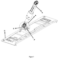
Figure 1 is a side perspective view of a base of the washing and/or drying device according to the present invention and a damper connected with the base. -
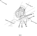
Figure 2 is a view of detail "A" shown inFigure 1 . -
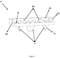
Figure 3 is a front perspective view of a supporting piece of the washing and/or drying device according to the present invention. - All the parts illustrated in the figures are individually assigned a reference numeral and the corresponding terms of these numbers are listed as follows:
Body base (G) Connecting region (K) Damper (S) Supporting piece (P) Rear wall (D1) Side wall (D2) Supporting wall (D3) Lug (T) Protrusion (T1) Hole (B) Detail (A) - The washing and/or drying devices such as washing machines and drying machines comprise a damper for absorbing movement/vibration at those parts such as a drum, chamber etc. where washing is performed, which is particularly generated while such processes as washing/wringing/drying are being performed. At one end, said damper is connected with the said chamber and at the other end, it is generally connected to the body base of the device. The body base typically comprises a connecting region in order to connect the damper to the said body base. The damper of the washing and/or drying device transfers the movement of the chamber to which it is connected to the said connecting region, during movement absorption, whereby the said connecting region is made subject to rotational movement and deformation over time. On the other hand, supporting pieces used to reduce/prevent said deformation may generate further noise during said movement. Therefore, with the present invention, there is provided a washing and/or drying device comprising a supporting piece independent from the said damper and located at the said connecting region so as to prevent deformation of the said connecting region, in which device noise generated during operation thereof is also reduced.
- The washing and/or drying device according to the present invention, as illustrated in
figures 1-3 , comprises at least one body (not shown); at least one body base (G) located at that part facing a floor where the body is situated; at least one chamber (not shown) which is located in the said body and in which stuff is put and washing/wringing/drying processes are performed; and at least one damper (S) which absorbs the movement of the said chamber during the washing/wringing/drying processes, and at least one end of which is connected to the said chamber and at least another end thereof is connected to at least one connecting region (K) of the said body base (G), which is preferably in the form of flange. The washing and/or drying device according to the present invention also comprises at least one plastic supporting piece (P) for preventing strike of the connecting region (K) thereto and making noise during the operation of the washing and/or drying device, which is preferably located at that part of the connecting region (K) facing the chamber (i.e. at that part facing away from the outer environment where the washing and/or drying device is situated and particularly so as not to be located under such structures as flanges that the connecting regions (K) may include) such that it is in contact with the connecting region (K), so as to prevent rotational movement of the connecting region (K) which may result from the force exerted on the chamber while the damper (S) is absorbing the movement of the chamber. In another preferred embodiment, said supporting piece (P) may be located at any side of the connecting region (K). - Said supporting piece (P) comprises at least one rear wall (D1) at a certain height which is located at that part facing the connecting region (K), which is preferably in contact with the connecting region (K) and extends so as to move away from the body base (G). Said rear wall (D1) prevents rotational movement of the connecting region (K) while preventing the moment generated by pulling the connecting region (K) towards center of the body base (G) by the damper (S) during the movement of the chamber.
- In a preferred embodiment of the invention, said supporting piece (P) comprises at least one lug (T) in order to engage and disengage it from the body base (G). In this embodiment, the washing and/or drying device also comprises at least one hole (not shown) for receiving said lug (T). With the said lug (T), montage of the supporting piece (P) on the body is facilitated and any possible montage errors are prevented. In another preferred embodiment, the washing and/or drying device may comprise at least another connecting member such as a screw for fixing the said supporting piece (P) on the body base (G) or at least one slide (not shown) so as to prevent the said supporting piece (P) from being fixed on the body base (G) in a reverse manner.
- In another preferred embodiment of the invention, the supporting piece (P) comprises at least two lugs (T) made of a flexible material and those ends of the said lugs (T) that are distal to the supporting piece (P) are inclined so as to move away from each other. In this embodiment, when the supporting piece (P) is fitted to the body base (G), said lugs (T) are positioned such that they exert power in an opposite direction to the body base (G). Thus, the supporting piece (P) is stably fixed on the body and a reliable supporting structure is achieved for the connecting region (K). In this embodiment, the lugs (T) comprise at least one protrusion (T1) positioned at that part facing towards the outer environment (i.e. at that part of the lugs (T) not facing each other). In this embodiment, when the lug (T) is positioned in the said hole, the surface of the said protrusion (T1) facing the body base (G) rests on the body base (G) in order to prevent the supporting piece (P) from being released from the body base (G). In order to release said supporting piece (P) from the body base (G), said flexible lugs (T) are moved so as to come close to each other, and when the protrusion (T1) is released from the body base (G), the supporting piece (P) may be disengaged from the body.
- In another alternative embodiment of the invention, said supporting piece (P) comprises at least one side wall (D2) which is positioned on at least one side of the said rear wall (D1) such that there is preferably a right angle between the rear wall (D1) and the side wall, in order to increase resistance of the supporting piece. In a preferred embodiment, an angle between the said rear wall (D1) and the side wall (D2) may be an angle other than a right angle.
- In another alternative embodiment of the invention, the supporting piece (P) comprises at least one supporting wall (D3) in order to increase the strength thereof and the said supporting wall (D3) is positioned such that it is preferably perpendicular to the rear wall (D1) and preferably parallel to the side wall (D2). In a preferred embodiment, the angle between the said rear wall (D1) and the supporting wall (D3) may be an angle other than a right angle and/or the supporting wall (D3) may be positioned such that there is a certain angle (i.e. larger than 0 deg) between the supporting wall and the side wall (D2).
- In another embodiment of the invention, said supporting piece (P) comprises a high mechanical strength material (i.e. thermoplastic and/or composite).
- In another preferred embodiment of the invention, the supporting piece (P) includes at least one space (B) in order not to become unnecessarily heavy and also to reduce production cost.
- With the supporting piece (P) provided in the washing device according to the present invention, deformation of the connecting region (K), to which the damper (S) of the washing device is connected, is prevented while any noise that may occur during the operation of the washing device is suppressed though an additional piece is employed. In addition, since the supporting piece (P) is independent from the damper (S) and the connecting region (K), said pieces upon which load is applied are replaced independent from each other.
Claims (15)
- A washing and/or drying device comprising at least one body; at least one body base (G) located at that part facing a floor where the body is situated; at least one chamber which is located in the said body and in which stuff is put and washing/wringing/drying processes are performed; and at least one damper (S) which absorbs the movement of the said chamber during the washing/wringing/drying processes, and at least one end of which is connected to the said chamber and at least another end thereof is connected to at least one connecting region (K) provided in the said body base (G), characterized by comprising at least one plastic supporting piece (P) for preventing strike of the connecting region (K) thereto and making noise during the operation of the washing and/or drying device, which piece is located such that it is in contact with the connecting region (K) so as to prevent rotational movement of the connecting region (K) which may result from the force exerted on the chamber while the damper (S) is absorbing the movement of the chamber.
- A washing and/or drying device according to claim 1, characterized in that said supporting piece (P) comprises at least one rear wall (D1) at a certain height which extends at that part facing the connecting region (K) so as to move away from the body base (G).
- A washing and/or drying device according to claim 1, characterized in that said supporting piece (P) comprises at least one lug (T) in order to engage and disengage it from the body base (G), and the washing and/or drying device also comprises at least one hole suitable for receiving said lug (T).
- A washing and/or drying device according to claim 1, characterized by comprising at least another connecting member for fixing the said supporting piece (P) on the body base (G).
- A washing and/or drying device according to claim 1, characterized by comprising at least one slide for fixing the said supporting piece (P) on the body base (G).
- A washing and/or drying device according to claim 1, characterized in that the supporting piece (P) comprises at least two lugs (T) made of a flexible material.
- A washing and/or drying device according to claim 6, characterized in that those ends of the said lugs (T) that are distal to the supporting piece (P) are inclined so as to move away from each other.
- A washing and/or drying device according to claim 7, characterized in that the lugs (T) comprises at least one protrusion (T1) positioned at that part facing towards the outer environment.
- A washing and/or drying device according to claim 2, characterized in that said supporting piece (P) comprises at least one side wall (D2) which is positioned on at least one side of the said rear wall (D1) in order to increase resistance of the supporting piece.
- A washing and/or drying device according to claim 9, characterized in that the side wall (D2) is positioned such that there is a right angle between the rear wall (D1) and the side wall.
- A washing and/or drying device according to claim 1, characterized in that the supporting piece (P) comprises at least one supporting wall (D3) in order to increase the strength thereof.
- A washing and/or drying device according to claim 2, characterized in that the supporting piece (P) comprises at least one supporting wall (D3) in order to increase the strength thereof.
- A washing and/or drying device according to claim 12, characterized in that said supporting wall (D3) is positioned such that it is perpendicular to the rear wall (D1).
- A washing and/or drying device according to claim 9, characterized in that the supporting wall (D3) is parallel to the side wall (D2).
- A washing and/or drying device according to claim 1, characterized in that the supporting piece (P) includes at least one space (B) in order not to become unnecessarily heavy and to reduce production cost.
Applications Claiming Priority (1)
| Application Number | Priority Date | Filing Date | Title |
|---|---|---|---|
| TR201508649 | 2015-07-10 |
Publications (2)
| Publication Number | Publication Date |
|---|---|
| EP3115495A1 true EP3115495A1 (en) | 2017-01-11 |
| EP3115495B1 EP3115495B1 (en) | 2018-08-08 |
Family
ID=55024726
Family Applications (1)
| Application Number | Title | Priority Date | Filing Date |
|---|---|---|---|
| EP15197359.1A Active EP3115495B1 (en) | 2015-07-10 | 2015-12-01 | Washing and/or drying device with a damper |
Country Status (1)
| Country | Link |
|---|---|
| EP (1) | EP3115495B1 (en) |
Families Citing this family (1)
| Publication number | Priority date | Publication date | Assignee | Title |
|---|---|---|---|---|
| EP4400642A1 (en) * | 2023-01-12 | 2024-07-17 | BSH Hausgeräte GmbH | Washing machine with improved shock absorber fixation and process for its manufacture |
Citations (8)
| Publication number | Priority date | Publication date | Assignee | Title |
|---|---|---|---|---|
| EP1388603A1 (en) * | 2002-08-09 | 2004-02-11 | Lg Electronics Inc. | A drum washing machine |
| US20050262886A1 (en) | 2004-06-01 | 2005-12-01 | Lg Electronics Inc. | Base assembly and washing machine with the same |
| CN1730782A (en) * | 2004-08-06 | 2006-02-08 | 乐金电子(天津)电器有限公司 | Vibration damper assembling structure of drum washing machine |
| EP1757724A2 (en) * | 2005-08-26 | 2007-02-28 | LG Electronics Inc. | Washing machine having damper-supporter |
| US20070044518A1 (en) | 2005-09-01 | 2007-03-01 | Samsung Electronics Co., Ltd. | Washing and/or drying machine having a damper connecting structure including a reinforcing portion |
| EP1783260A1 (en) * | 2005-11-04 | 2007-05-09 | IAR-SILTAL S.p.A. | Machine for washing and/or drying laundry |
| KR20080057073A (en) * | 2006-12-19 | 2008-06-24 | 엘지전자 주식회사 | Drum washing machine |
| EP2848723A1 (en) * | 2013-09-17 | 2015-03-18 | Electrolux Appliances Aktiebolag | Washing laundry machine with damper elements |
-
2015
- 2015-12-01 EP EP15197359.1A patent/EP3115495B1/en active Active
Patent Citations (8)
| Publication number | Priority date | Publication date | Assignee | Title |
|---|---|---|---|---|
| EP1388603A1 (en) * | 2002-08-09 | 2004-02-11 | Lg Electronics Inc. | A drum washing machine |
| US20050262886A1 (en) | 2004-06-01 | 2005-12-01 | Lg Electronics Inc. | Base assembly and washing machine with the same |
| CN1730782A (en) * | 2004-08-06 | 2006-02-08 | 乐金电子(天津)电器有限公司 | Vibration damper assembling structure of drum washing machine |
| EP1757724A2 (en) * | 2005-08-26 | 2007-02-28 | LG Electronics Inc. | Washing machine having damper-supporter |
| US20070044518A1 (en) | 2005-09-01 | 2007-03-01 | Samsung Electronics Co., Ltd. | Washing and/or drying machine having a damper connecting structure including a reinforcing portion |
| EP1783260A1 (en) * | 2005-11-04 | 2007-05-09 | IAR-SILTAL S.p.A. | Machine for washing and/or drying laundry |
| KR20080057073A (en) * | 2006-12-19 | 2008-06-24 | 엘지전자 주식회사 | Drum washing machine |
| EP2848723A1 (en) * | 2013-09-17 | 2015-03-18 | Electrolux Appliances Aktiebolag | Washing laundry machine with damper elements |
Also Published As
| Publication number | Publication date |
|---|---|
| EP3115495B1 (en) | 2018-08-08 |
Similar Documents
| Publication | Publication Date | Title |
|---|---|---|
| US9486069B2 (en) | Vibration-damped furniture piece in the form of a table | |
| EP3373108B1 (en) | Bracket for fixing electronic device and mechanism for fixing electronic device | |
| EP2025576A2 (en) | Steering wheel position adjustment device | |
| EP3046853B1 (en) | Rack protector | |
| JP6771110B2 (en) | Switch cabinet mounting plate assembly | |
| JP2008542661A (en) | Device for fixing at least one object to a support member provided with a fixing bolt | |
| CN104754988A (en) | Slide attachment or detachment device for drawer | |
| JP2015205587A (en) | Seat slide device for vehicle | |
| US7703829B2 (en) | Instrument panel energy transferring system | |
| EP3115495B1 (en) | Washing and/or drying device with a damper | |
| WO2018150915A1 (en) | Vibration damping device | |
| KR100748526B1 (en) | Washing machine with damper support | |
| JP5899942B2 (en) | Fixing device and image forming apparatus | |
| JP2016159855A (en) | Bumper absorber attachment structure | |
| JP5165442B2 (en) | Vibration control device | |
| JP2020513543A (en) | Locking means for transport protection of leveling device with integral load cell | |
| JP6467161B2 (en) | Floor panel | |
| EP2702197B1 (en) | Appliance leg | |
| JP6269136B2 (en) | Steering device | |
| EP3168358A1 (en) | Washing machine with adjustable supports | |
| CN106130245B (en) | Simple damping structure and motor mounting structure | |
| KR101613567B1 (en) | Vibration isolation mount | |
| KR101688797B1 (en) | Damper assemblay for washing machine | |
| KR101699282B1 (en) | A vibrating suction device | |
| KR102046696B1 (en) | Mean for fastening pin |
Legal Events
| Date | Code | Title | Description |
|---|---|---|---|
| PUAI | Public reference made under article 153(3) epc to a published international application that has entered the european phase |
Free format text: ORIGINAL CODE: 0009012 |
|
| AK | Designated contracting states |
Kind code of ref document: A1 Designated state(s): AL AT BE BG CH CY CZ DE DK EE ES FI FR GB GR HR HU IE IS IT LI LT LU LV MC MK MT NL NO PL PT RO RS SE SI SK SM TR |
|
| AX | Request for extension of the european patent |
Extension state: BA ME |
|
| 17P | Request for examination filed |
Effective date: 20170710 |
|
| RBV | Designated contracting states (corrected) |
Designated state(s): AL AT BE BG CH CY CZ DE DK EE ES FI FR GB GR HR HU IE IS IT LI LT LU LV MC MK MT NL NO PL PT RO RS SE SI SK SM TR |
|
| 17Q | First examination report despatched |
Effective date: 20170904 |
|
| GRAP | Despatch of communication of intention to grant a patent |
Free format text: ORIGINAL CODE: EPIDOSNIGR1 |
|
| INTG | Intention to grant announced |
Effective date: 20180301 |
|
| GRAS | Grant fee paid |
Free format text: ORIGINAL CODE: EPIDOSNIGR3 |
|
| GRAA | (expected) grant |
Free format text: ORIGINAL CODE: 0009210 |
|
| AK | Designated contracting states |
Kind code of ref document: B1 Designated state(s): AL AT BE BG CH CY CZ DE DK EE ES FI FR GB GR HR HU IE IS IT LI LT LU LV MC MK MT NL NO PL PT RO RS SE SI SK SM TR |
|
| REG | Reference to a national code |
Ref country code: GB Ref legal event code: FG4D |
|
| REG | Reference to a national code |
Ref country code: CH Ref legal event code: EP Ref country code: AT Ref legal event code: REF Ref document number: 1027149 Country of ref document: AT Kind code of ref document: T Effective date: 20180815 |
|
| REG | Reference to a national code |
Ref country code: IE Ref legal event code: FG4D |
|
| REG | Reference to a national code |
Ref country code: DE Ref legal event code: R096 Ref document number: 602015014580 Country of ref document: DE |
|
| REG | Reference to a national code |
Ref country code: NL Ref legal event code: MP Effective date: 20180808 |
|
| REG | Reference to a national code |
Ref country code: LT Ref legal event code: MG4D |
|
| REG | Reference to a national code |
Ref country code: AT Ref legal event code: MK05 Ref document number: 1027149 Country of ref document: AT Kind code of ref document: T Effective date: 20180808 |
|
| PG25 | Lapsed in a contracting state [announced via postgrant information from national office to epo] |
Ref country code: SE Free format text: LAPSE BECAUSE OF FAILURE TO SUBMIT A TRANSLATION OF THE DESCRIPTION OR TO PAY THE FEE WITHIN THE PRESCRIBED TIME-LIMIT Effective date: 20180808 Ref country code: PL Free format text: LAPSE BECAUSE OF FAILURE TO SUBMIT A TRANSLATION OF THE DESCRIPTION OR TO PAY THE FEE WITHIN THE PRESCRIBED TIME-LIMIT Effective date: 20180808 Ref country code: LT Free format text: LAPSE BECAUSE OF FAILURE TO SUBMIT A TRANSLATION OF THE DESCRIPTION OR TO PAY THE FEE WITHIN THE PRESCRIBED TIME-LIMIT Effective date: 20180808 Ref country code: RS Free format text: LAPSE BECAUSE OF FAILURE TO SUBMIT A TRANSLATION OF THE DESCRIPTION OR TO PAY THE FEE WITHIN THE PRESCRIBED TIME-LIMIT Effective date: 20180808 Ref country code: FI Free format text: LAPSE BECAUSE OF FAILURE TO SUBMIT A TRANSLATION OF THE DESCRIPTION OR TO PAY THE FEE WITHIN THE PRESCRIBED TIME-LIMIT Effective date: 20180808 Ref country code: NL Free format text: LAPSE BECAUSE OF FAILURE TO SUBMIT A TRANSLATION OF THE DESCRIPTION OR TO PAY THE FEE WITHIN THE PRESCRIBED TIME-LIMIT Effective date: 20180808 Ref country code: BG Free format text: LAPSE BECAUSE OF FAILURE TO SUBMIT A TRANSLATION OF THE DESCRIPTION OR TO PAY THE FEE WITHIN THE PRESCRIBED TIME-LIMIT Effective date: 20181108 Ref country code: GR Free format text: LAPSE BECAUSE OF FAILURE TO SUBMIT A TRANSLATION OF THE DESCRIPTION OR TO PAY THE FEE WITHIN THE PRESCRIBED TIME-LIMIT Effective date: 20181109 Ref country code: AT Free format text: LAPSE BECAUSE OF FAILURE TO SUBMIT A TRANSLATION OF THE DESCRIPTION OR TO PAY THE FEE WITHIN THE PRESCRIBED TIME-LIMIT Effective date: 20180808 Ref country code: NO Free format text: LAPSE BECAUSE OF FAILURE TO SUBMIT A TRANSLATION OF THE DESCRIPTION OR TO PAY THE FEE WITHIN THE PRESCRIBED TIME-LIMIT Effective date: 20181108 Ref country code: IS Free format text: LAPSE BECAUSE OF FAILURE TO SUBMIT A TRANSLATION OF THE DESCRIPTION OR TO PAY THE FEE WITHIN THE PRESCRIBED TIME-LIMIT Effective date: 20181208 |
|
| PG25 | Lapsed in a contracting state [announced via postgrant information from national office to epo] |
Ref country code: HR Free format text: LAPSE BECAUSE OF FAILURE TO SUBMIT A TRANSLATION OF THE DESCRIPTION OR TO PAY THE FEE WITHIN THE PRESCRIBED TIME-LIMIT Effective date: 20180808 Ref country code: LV Free format text: LAPSE BECAUSE OF FAILURE TO SUBMIT A TRANSLATION OF THE DESCRIPTION OR TO PAY THE FEE WITHIN THE PRESCRIBED TIME-LIMIT Effective date: 20180808 Ref country code: AL Free format text: LAPSE BECAUSE OF FAILURE TO SUBMIT A TRANSLATION OF THE DESCRIPTION OR TO PAY THE FEE WITHIN THE PRESCRIBED TIME-LIMIT Effective date: 20180808 |
|
| PG25 | Lapsed in a contracting state [announced via postgrant information from national office to epo] |
Ref country code: EE Free format text: LAPSE BECAUSE OF FAILURE TO SUBMIT A TRANSLATION OF THE DESCRIPTION OR TO PAY THE FEE WITHIN THE PRESCRIBED TIME-LIMIT Effective date: 20180808 Ref country code: IT Free format text: LAPSE BECAUSE OF FAILURE TO SUBMIT A TRANSLATION OF THE DESCRIPTION OR TO PAY THE FEE WITHIN THE PRESCRIBED TIME-LIMIT Effective date: 20180808 Ref country code: CZ Free format text: LAPSE BECAUSE OF FAILURE TO SUBMIT A TRANSLATION OF THE DESCRIPTION OR TO PAY THE FEE WITHIN THE PRESCRIBED TIME-LIMIT Effective date: 20180808 Ref country code: RO Free format text: LAPSE BECAUSE OF FAILURE TO SUBMIT A TRANSLATION OF THE DESCRIPTION OR TO PAY THE FEE WITHIN THE PRESCRIBED TIME-LIMIT Effective date: 20180808 Ref country code: ES Free format text: LAPSE BECAUSE OF FAILURE TO SUBMIT A TRANSLATION OF THE DESCRIPTION OR TO PAY THE FEE WITHIN THE PRESCRIBED TIME-LIMIT Effective date: 20180808 |
|
| REG | Reference to a national code |
Ref country code: DE Ref legal event code: R097 Ref document number: 602015014580 Country of ref document: DE |
|
| PG25 | Lapsed in a contracting state [announced via postgrant information from national office to epo] |
Ref country code: SK Free format text: LAPSE BECAUSE OF FAILURE TO SUBMIT A TRANSLATION OF THE DESCRIPTION OR TO PAY THE FEE WITHIN THE PRESCRIBED TIME-LIMIT Effective date: 20180808 Ref country code: DK Free format text: LAPSE BECAUSE OF FAILURE TO SUBMIT A TRANSLATION OF THE DESCRIPTION OR TO PAY THE FEE WITHIN THE PRESCRIBED TIME-LIMIT Effective date: 20180808 Ref country code: SM Free format text: LAPSE BECAUSE OF FAILURE TO SUBMIT A TRANSLATION OF THE DESCRIPTION OR TO PAY THE FEE WITHIN THE PRESCRIBED TIME-LIMIT Effective date: 20180808 |
|
| PLBE | No opposition filed within time limit |
Free format text: ORIGINAL CODE: 0009261 |
|
| STAA | Information on the status of an ep patent application or granted ep patent |
Free format text: STATUS: NO OPPOSITION FILED WITHIN TIME LIMIT |
|
| 26N | No opposition filed |
Effective date: 20190509 |
|
| REG | Reference to a national code |
Ref country code: CH Ref legal event code: PL |
|
| PG25 | Lapsed in a contracting state [announced via postgrant information from national office to epo] |
Ref country code: SI Free format text: LAPSE BECAUSE OF FAILURE TO SUBMIT A TRANSLATION OF THE DESCRIPTION OR TO PAY THE FEE WITHIN THE PRESCRIBED TIME-LIMIT Effective date: 20180808 Ref country code: LU Free format text: LAPSE BECAUSE OF NON-PAYMENT OF DUE FEES Effective date: 20181201 Ref country code: MC Free format text: LAPSE BECAUSE OF FAILURE TO SUBMIT A TRANSLATION OF THE DESCRIPTION OR TO PAY THE FEE WITHIN THE PRESCRIBED TIME-LIMIT Effective date: 20180808 |
|
| REG | Reference to a national code |
Ref country code: IE Ref legal event code: MM4A |
|
| REG | Reference to a national code |
Ref country code: BE Ref legal event code: MM Effective date: 20181231 |
|
| PG25 | Lapsed in a contracting state [announced via postgrant information from national office to epo] |
Ref country code: IE Free format text: LAPSE BECAUSE OF NON-PAYMENT OF DUE FEES Effective date: 20181201 |
|
| PG25 | Lapsed in a contracting state [announced via postgrant information from national office to epo] |
Ref country code: BE Free format text: LAPSE BECAUSE OF NON-PAYMENT OF DUE FEES Effective date: 20181231 |
|
| PG25 | Lapsed in a contracting state [announced via postgrant information from national office to epo] |
Ref country code: CH Free format text: LAPSE BECAUSE OF NON-PAYMENT OF DUE FEES Effective date: 20181231 Ref country code: LI Free format text: LAPSE BECAUSE OF NON-PAYMENT OF DUE FEES Effective date: 20181231 |
|
| PG25 | Lapsed in a contracting state [announced via postgrant information from national office to epo] |
Ref country code: MT Free format text: LAPSE BECAUSE OF NON-PAYMENT OF DUE FEES Effective date: 20181201 |
|
| PG25 | Lapsed in a contracting state [announced via postgrant information from national office to epo] |
Ref country code: PT Free format text: LAPSE BECAUSE OF FAILURE TO SUBMIT A TRANSLATION OF THE DESCRIPTION OR TO PAY THE FEE WITHIN THE PRESCRIBED TIME-LIMIT Effective date: 20180808 |
|
| PG25 | Lapsed in a contracting state [announced via postgrant information from national office to epo] |
Ref country code: HU Free format text: LAPSE BECAUSE OF FAILURE TO SUBMIT A TRANSLATION OF THE DESCRIPTION OR TO PAY THE FEE WITHIN THE PRESCRIBED TIME-LIMIT; INVALID AB INITIO Effective date: 20151201 Ref country code: MK Free format text: LAPSE BECAUSE OF NON-PAYMENT OF DUE FEES Effective date: 20180808 Ref country code: CY Free format text: LAPSE BECAUSE OF FAILURE TO SUBMIT A TRANSLATION OF THE DESCRIPTION OR TO PAY THE FEE WITHIN THE PRESCRIBED TIME-LIMIT Effective date: 20180808 |
|
| REG | Reference to a national code |
Ref country code: DE Ref legal event code: R084 Ref document number: 602015014580 Country of ref document: DE |
|
| PGFP | Annual fee paid to national office [announced via postgrant information from national office to epo] |
Ref country code: DE Payment date: 20251211 Year of fee payment: 11 |
|
| PGFP | Annual fee paid to national office [announced via postgrant information from national office to epo] |
Ref country code: GB Payment date: 20251219 Year of fee payment: 11 |
|
| PGFP | Annual fee paid to national office [announced via postgrant information from national office to epo] |
Ref country code: FR Payment date: 20251223 Year of fee payment: 11 |
|
| PGFP | Annual fee paid to national office [announced via postgrant information from national office to epo] |
Ref country code: TR Payment date: 20251128 Year of fee payment: 11 |