EP3115398A1 - Composite sliding member and heat-resistant composite sliding member for oa equipment - Google Patents
Composite sliding member and heat-resistant composite sliding member for oa equipment Download PDFInfo
- Publication number
- EP3115398A1 EP3115398A1 EP15758787.4A EP15758787A EP3115398A1 EP 3115398 A1 EP3115398 A1 EP 3115398A1 EP 15758787 A EP15758787 A EP 15758787A EP 3115398 A1 EP3115398 A1 EP 3115398A1
- Authority
- EP
- European Patent Office
- Prior art keywords
- fiber
- resin
- heat resistant
- woven fabric
- monofilaments
- Prior art date
- Legal status (The legal status is an assumption and is not a legal conclusion. Google has not performed a legal analysis and makes no representation as to the accuracy of the status listed.)
- Withdrawn
Links
- 239000002131 composite material Substances 0.000 title claims abstract description 54
- 229920005989 resin Polymers 0.000 claims abstract description 130
- 239000011347 resin Substances 0.000 claims abstract description 130
- 239000000835 fiber Substances 0.000 claims abstract description 125
- 239000002759 woven fabric Substances 0.000 claims abstract description 82
- 239000012210 heat-resistant fiber Substances 0.000 claims abstract description 72
- 239000002344 surface layer Substances 0.000 claims abstract description 45
- 229920005992 thermoplastic resin Polymers 0.000 claims description 29
- 239000004734 Polyphenylene sulfide Substances 0.000 claims description 21
- 229920000069 polyphenylene sulfide Polymers 0.000 claims description 21
- 239000000463 material Substances 0.000 claims description 20
- 239000004973 liquid crystal related substance Substances 0.000 claims description 11
- 229920001225 polyester resin Polymers 0.000 claims description 7
- 239000004645 polyester resin Substances 0.000 claims description 7
- 239000004744 fabric Substances 0.000 abstract description 16
- 238000005299 abrasion Methods 0.000 abstract description 11
- YCKRFDGAMUMZLT-UHFFFAOYSA-N Fluorine atom Chemical compound [F] YCKRFDGAMUMZLT-UHFFFAOYSA-N 0.000 abstract description 9
- 229910052731 fluorine Inorganic materials 0.000 abstract description 9
- 239000011737 fluorine Substances 0.000 abstract description 9
- 239000000758 substrate Substances 0.000 description 19
- 238000001746 injection moulding Methods 0.000 description 17
- 238000000034 method Methods 0.000 description 16
- -1 polytetrafluoroethylene Polymers 0.000 description 14
- 230000000052 comparative effect Effects 0.000 description 11
- 238000012360 testing method Methods 0.000 description 10
- 238000002347 injection Methods 0.000 description 9
- 239000007924 injection Substances 0.000 description 9
- 238000005259 measurement Methods 0.000 description 8
- 238000009941 weaving Methods 0.000 description 7
- 229920000106 Liquid crystal polymer Polymers 0.000 description 6
- 239000004977 Liquid-crystal polymers (LCPs) Substances 0.000 description 6
- 229920001707 polybutylene terephthalate Polymers 0.000 description 6
- 229920000728 polyester Polymers 0.000 description 6
- 229920000139 polyethylene terephthalate Polymers 0.000 description 6
- 239000005020 polyethylene terephthalate Substances 0.000 description 6
- 238000005516 engineering process Methods 0.000 description 5
- 230000004927 fusion Effects 0.000 description 5
- 238000002844 melting Methods 0.000 description 5
- 230000008018 melting Effects 0.000 description 5
- 230000010354 integration Effects 0.000 description 4
- 238000000465 moulding Methods 0.000 description 4
- 229920001343 polytetrafluoroethylene Polymers 0.000 description 4
- 239000004810 polytetrafluoroethylene Substances 0.000 description 4
- 239000000126 substance Substances 0.000 description 4
- BFKJFAAPBSQJPD-UHFFFAOYSA-N tetrafluoroethene Chemical group FC(F)=C(F)F BFKJFAAPBSQJPD-UHFFFAOYSA-N 0.000 description 4
- 239000004696 Poly ether ether ketone Substances 0.000 description 3
- 230000015556 catabolic process Effects 0.000 description 3
- 238000006731 degradation reaction Methods 0.000 description 3
- 229920001971 elastomer Polymers 0.000 description 3
- 238000010438 heat treatment Methods 0.000 description 3
- 229920002530 polyetherether ketone Polymers 0.000 description 3
- 239000005060 rubber Substances 0.000 description 3
- 239000004697 Polyetherimide Substances 0.000 description 2
- PPBRXRYQALVLMV-UHFFFAOYSA-N Styrene Chemical compound C=CC1=CC=CC=C1 PPBRXRYQALVLMV-UHFFFAOYSA-N 0.000 description 2
- 229910052799 carbon Inorganic materials 0.000 description 2
- 239000011248 coating agent Substances 0.000 description 2
- 238000000576 coating method Methods 0.000 description 2
- 150000001875 compounds Chemical class 0.000 description 2
- 239000000470 constituent Substances 0.000 description 2
- 230000000694 effects Effects 0.000 description 2
- 229920001519 homopolymer Polymers 0.000 description 2
- 238000005470 impregnation Methods 0.000 description 2
- 238000010348 incorporation Methods 0.000 description 2
- 238000012423 maintenance Methods 0.000 description 2
- 238000004519 manufacturing process Methods 0.000 description 2
- 239000000178 monomer Substances 0.000 description 2
- 229920001601 polyetherimide Polymers 0.000 description 2
- 229920003051 synthetic elastomer Polymers 0.000 description 2
- 230000004580 weight loss Effects 0.000 description 2
- NLHHRLWOUZZQLW-UHFFFAOYSA-N Acrylonitrile Chemical compound C=CC#N NLHHRLWOUZZQLW-UHFFFAOYSA-N 0.000 description 1
- OKTJSMMVPCPJKN-UHFFFAOYSA-N Carbon Chemical compound [C] OKTJSMMVPCPJKN-UHFFFAOYSA-N 0.000 description 1
- 229920000459 Nitrile rubber Polymers 0.000 description 1
- 239000005062 Polybutadiene Substances 0.000 description 1
- 239000004698 Polyethylene Substances 0.000 description 1
- 239000004743 Polypropylene Substances 0.000 description 1
- 239000004793 Polystyrene Substances 0.000 description 1
- 229910000831 Steel Inorganic materials 0.000 description 1
- 239000004433 Thermoplastic polyurethane Substances 0.000 description 1
- 229920013629 Torelina Polymers 0.000 description 1
- 239000004742 Torelina™ Substances 0.000 description 1
- BZHJMEDXRYGGRV-UHFFFAOYSA-N Vinyl chloride Chemical compound ClC=C BZHJMEDXRYGGRV-UHFFFAOYSA-N 0.000 description 1
- 229920000122 acrylonitrile butadiene styrene Polymers 0.000 description 1
- 239000000654 additive Substances 0.000 description 1
- 230000001464 adherent effect Effects 0.000 description 1
- 230000015572 biosynthetic process Effects 0.000 description 1
- 239000003086 colorant Substances 0.000 description 1
- 238000000748 compression moulding Methods 0.000 description 1
- 238000012790 confirmation Methods 0.000 description 1
- 229920001577 copolymer Polymers 0.000 description 1
- 238000005520 cutting process Methods 0.000 description 1
- 239000000806 elastomer Substances 0.000 description 1
- 230000001747 exhibiting effect Effects 0.000 description 1
- 230000002349 favourable effect Effects 0.000 description 1
- 239000002657 fibrous material Substances 0.000 description 1
- 239000002783 friction material Substances 0.000 description 1
- 239000011521 glass Substances 0.000 description 1
- HCDGVLDPFQMKDK-UHFFFAOYSA-N hexafluoropropylene Chemical group FC(F)=C(F)C(F)(F)F HCDGVLDPFQMKDK-UHFFFAOYSA-N 0.000 description 1
- 230000003301 hydrolyzing effect Effects 0.000 description 1
- 229910010272 inorganic material Inorganic materials 0.000 description 1
- 239000011147 inorganic material Substances 0.000 description 1
- QZUPTXGVPYNUIT-UHFFFAOYSA-N isophthalamide Chemical compound NC(=O)C1=CC=CC(C(N)=O)=C1 QZUPTXGVPYNUIT-UHFFFAOYSA-N 0.000 description 1
- 230000007774 longterm Effects 0.000 description 1
- 239000000155 melt Substances 0.000 description 1
- 239000000203 mixture Substances 0.000 description 1
- 239000012778 molding material Substances 0.000 description 1
- 239000004745 nonwoven fabric Substances 0.000 description 1
- 238000007719 peel strength test Methods 0.000 description 1
- 229920003023 plastic Polymers 0.000 description 1
- 239000004033 plastic Substances 0.000 description 1
- 229920001084 poly(chloroprene) Polymers 0.000 description 1
- 229920006122 polyamide resin Polymers 0.000 description 1
- 229920002857 polybutadiene Polymers 0.000 description 1
- 229920005668 polycarbonate resin Polymers 0.000 description 1
- 239000004431 polycarbonate resin Substances 0.000 description 1
- 229920000573 polyethylene Polymers 0.000 description 1
- 229920001155 polypropylene Polymers 0.000 description 1
- 229920002223 polystyrene Polymers 0.000 description 1
- 238000012545 processing Methods 0.000 description 1
- 102200082816 rs34868397 Human genes 0.000 description 1
- 238000009991 scouring Methods 0.000 description 1
- 238000007493 shaping process Methods 0.000 description 1
- 239000003381 stabilizer Substances 0.000 description 1
- 239000007858 starting material Substances 0.000 description 1
- 239000010959 steel Substances 0.000 description 1
- 230000003746 surface roughness Effects 0.000 description 1
- 239000005061 synthetic rubber Substances 0.000 description 1
- 230000008646 thermal stress Effects 0.000 description 1
- 229920002803 thermoplastic polyurethane Polymers 0.000 description 1
- 125000000391 vinyl group Chemical group [H]C([*])=C([H])[H] 0.000 description 1
Images
Classifications
-
- B—PERFORMING OPERATIONS; TRANSPORTING
- B32—LAYERED PRODUCTS
- B32B—LAYERED PRODUCTS, i.e. PRODUCTS BUILT-UP OF STRATA OF FLAT OR NON-FLAT, e.g. CELLULAR OR HONEYCOMB, FORM
- B32B27/00—Layered products comprising a layer of synthetic resin
- B32B27/12—Layered products comprising a layer of synthetic resin next to a fibrous or filamentary layer
-
- B—PERFORMING OPERATIONS; TRANSPORTING
- B32—LAYERED PRODUCTS
- B32B—LAYERED PRODUCTS, i.e. PRODUCTS BUILT-UP OF STRATA OF FLAT OR NON-FLAT, e.g. CELLULAR OR HONEYCOMB, FORM
- B32B27/00—Layered products comprising a layer of synthetic resin
- B32B27/28—Layered products comprising a layer of synthetic resin comprising synthetic resins not wholly covered by any one of the sub-groups B32B27/30 - B32B27/42
-
- B—PERFORMING OPERATIONS; TRANSPORTING
- B32—LAYERED PRODUCTS
- B32B—LAYERED PRODUCTS, i.e. PRODUCTS BUILT-UP OF STRATA OF FLAT OR NON-FLAT, e.g. CELLULAR OR HONEYCOMB, FORM
- B32B27/00—Layered products comprising a layer of synthetic resin
- B32B27/28—Layered products comprising a layer of synthetic resin comprising synthetic resins not wholly covered by any one of the sub-groups B32B27/30 - B32B27/42
- B32B27/286—Layered products comprising a layer of synthetic resin comprising synthetic resins not wholly covered by any one of the sub-groups B32B27/30 - B32B27/42 comprising polysulphones; polysulfides
-
- B—PERFORMING OPERATIONS; TRANSPORTING
- B32—LAYERED PRODUCTS
- B32B—LAYERED PRODUCTS, i.e. PRODUCTS BUILT-UP OF STRATA OF FLAT OR NON-FLAT, e.g. CELLULAR OR HONEYCOMB, FORM
- B32B27/00—Layered products comprising a layer of synthetic resin
- B32B27/28—Layered products comprising a layer of synthetic resin comprising synthetic resins not wholly covered by any one of the sub-groups B32B27/30 - B32B27/42
- B32B27/288—Layered products comprising a layer of synthetic resin comprising synthetic resins not wholly covered by any one of the sub-groups B32B27/30 - B32B27/42 comprising polyketones
-
- B—PERFORMING OPERATIONS; TRANSPORTING
- B32—LAYERED PRODUCTS
- B32B—LAYERED PRODUCTS, i.e. PRODUCTS BUILT-UP OF STRATA OF FLAT OR NON-FLAT, e.g. CELLULAR OR HONEYCOMB, FORM
- B32B27/00—Layered products comprising a layer of synthetic resin
- B32B27/36—Layered products comprising a layer of synthetic resin comprising polyesters
-
- B—PERFORMING OPERATIONS; TRANSPORTING
- B32—LAYERED PRODUCTS
- B32B—LAYERED PRODUCTS, i.e. PRODUCTS BUILT-UP OF STRATA OF FLAT OR NON-FLAT, e.g. CELLULAR OR HONEYCOMB, FORM
- B32B3/00—Layered products comprising a layer with external or internal discontinuities or unevennesses, or a layer of non-planar shape; Layered products comprising a layer having particular features of form
- B32B3/26—Layered products comprising a layer with external or internal discontinuities or unevennesses, or a layer of non-planar shape; Layered products comprising a layer having particular features of form characterised by a particular shape of the outline of the cross-section of a continuous layer; characterised by a layer with cavities or internal voids ; characterised by an apertured layer
- B32B3/28—Layered products comprising a layer with external or internal discontinuities or unevennesses, or a layer of non-planar shape; Layered products comprising a layer having particular features of form characterised by a particular shape of the outline of the cross-section of a continuous layer; characterised by a layer with cavities or internal voids ; characterised by an apertured layer characterised by a layer comprising a deformed thin sheet, i.e. the layer having its entire thickness deformed out of the plane, e.g. corrugated, crumpled
-
- B—PERFORMING OPERATIONS; TRANSPORTING
- B32—LAYERED PRODUCTS
- B32B—LAYERED PRODUCTS, i.e. PRODUCTS BUILT-UP OF STRATA OF FLAT OR NON-FLAT, e.g. CELLULAR OR HONEYCOMB, FORM
- B32B5/00—Layered products characterised by the non- homogeneity or physical structure, i.e. comprising a fibrous, filamentary, particulate or foam layer; Layered products characterised by having a layer differing constitutionally or physically in different parts
- B32B5/02—Layered products characterised by the non- homogeneity or physical structure, i.e. comprising a fibrous, filamentary, particulate or foam layer; Layered products characterised by having a layer differing constitutionally or physically in different parts characterised by structural features of a fibrous or filamentary layer
- B32B5/024—Woven fabric
-
- B—PERFORMING OPERATIONS; TRANSPORTING
- B32—LAYERED PRODUCTS
- B32B—LAYERED PRODUCTS, i.e. PRODUCTS BUILT-UP OF STRATA OF FLAT OR NON-FLAT, e.g. CELLULAR OR HONEYCOMB, FORM
- B32B5/00—Layered products characterised by the non- homogeneity or physical structure, i.e. comprising a fibrous, filamentary, particulate or foam layer; Layered products characterised by having a layer differing constitutionally or physically in different parts
- B32B5/02—Layered products characterised by the non- homogeneity or physical structure, i.e. comprising a fibrous, filamentary, particulate or foam layer; Layered products characterised by having a layer differing constitutionally or physically in different parts characterised by structural features of a fibrous or filamentary layer
- B32B5/12—Layered products characterised by the non- homogeneity or physical structure, i.e. comprising a fibrous, filamentary, particulate or foam layer; Layered products characterised by having a layer differing constitutionally or physically in different parts characterised by structural features of a fibrous or filamentary layer characterised by the relative arrangement of fibres or filaments of different layers, e.g. the fibres or filaments being parallel or perpendicular to each other
-
- B—PERFORMING OPERATIONS; TRANSPORTING
- B32—LAYERED PRODUCTS
- B32B—LAYERED PRODUCTS, i.e. PRODUCTS BUILT-UP OF STRATA OF FLAT OR NON-FLAT, e.g. CELLULAR OR HONEYCOMB, FORM
- B32B5/00—Layered products characterised by the non- homogeneity or physical structure, i.e. comprising a fibrous, filamentary, particulate or foam layer; Layered products characterised by having a layer differing constitutionally or physically in different parts
- B32B5/22—Layered products characterised by the non- homogeneity or physical structure, i.e. comprising a fibrous, filamentary, particulate or foam layer; Layered products characterised by having a layer differing constitutionally or physically in different parts characterised by the presence of two or more layers which are next to each other and are fibrous, filamentary, formed of particles or foamed
- B32B5/24—Layered products characterised by the non- homogeneity or physical structure, i.e. comprising a fibrous, filamentary, particulate or foam layer; Layered products characterised by having a layer differing constitutionally or physically in different parts characterised by the presence of two or more layers which are next to each other and are fibrous, filamentary, formed of particles or foamed one layer being a fibrous or filamentary layer
-
- B—PERFORMING OPERATIONS; TRANSPORTING
- B32—LAYERED PRODUCTS
- B32B—LAYERED PRODUCTS, i.e. PRODUCTS BUILT-UP OF STRATA OF FLAT OR NON-FLAT, e.g. CELLULAR OR HONEYCOMB, FORM
- B32B5/00—Layered products characterised by the non- homogeneity or physical structure, i.e. comprising a fibrous, filamentary, particulate or foam layer; Layered products characterised by having a layer differing constitutionally or physically in different parts
- B32B5/22—Layered products characterised by the non- homogeneity or physical structure, i.e. comprising a fibrous, filamentary, particulate or foam layer; Layered products characterised by having a layer differing constitutionally or physically in different parts characterised by the presence of two or more layers which are next to each other and are fibrous, filamentary, formed of particles or foamed
- B32B5/24—Layered products characterised by the non- homogeneity or physical structure, i.e. comprising a fibrous, filamentary, particulate or foam layer; Layered products characterised by having a layer differing constitutionally or physically in different parts characterised by the presence of two or more layers which are next to each other and are fibrous, filamentary, formed of particles or foamed one layer being a fibrous or filamentary layer
- B32B5/26—Layered products characterised by the non- homogeneity or physical structure, i.e. comprising a fibrous, filamentary, particulate or foam layer; Layered products characterised by having a layer differing constitutionally or physically in different parts characterised by the presence of two or more layers which are next to each other and are fibrous, filamentary, formed of particles or foamed one layer being a fibrous or filamentary layer another layer next to it also being fibrous or filamentary
-
- B—PERFORMING OPERATIONS; TRANSPORTING
- B32—LAYERED PRODUCTS
- B32B—LAYERED PRODUCTS, i.e. PRODUCTS BUILT-UP OF STRATA OF FLAT OR NON-FLAT, e.g. CELLULAR OR HONEYCOMB, FORM
- B32B7/00—Layered products characterised by the relation between layers; Layered products characterised by the relative orientation of features between layers, or by the relative values of a measurable parameter between layers, i.e. products comprising layers having different physical, chemical or physicochemical properties; Layered products characterised by the interconnection of layers
- B32B7/04—Interconnection of layers
-
- B—PERFORMING OPERATIONS; TRANSPORTING
- B32—LAYERED PRODUCTS
- B32B—LAYERED PRODUCTS, i.e. PRODUCTS BUILT-UP OF STRATA OF FLAT OR NON-FLAT, e.g. CELLULAR OR HONEYCOMB, FORM
- B32B7/00—Layered products characterised by the relation between layers; Layered products characterised by the relative orientation of features between layers, or by the relative values of a measurable parameter between layers, i.e. products comprising layers having different physical, chemical or physicochemical properties; Layered products characterised by the interconnection of layers
- B32B7/04—Interconnection of layers
- B32B7/12—Interconnection of layers using interposed adhesives or interposed materials with bonding properties
-
- C—CHEMISTRY; METALLURGY
- C10—PETROLEUM, GAS OR COKE INDUSTRIES; TECHNICAL GASES CONTAINING CARBON MONOXIDE; FUELS; LUBRICANTS; PEAT
- C10M—LUBRICATING COMPOSITIONS; USE OF CHEMICAL SUBSTANCES EITHER ALONE OR AS LUBRICATING INGREDIENTS IN A LUBRICATING COMPOSITION
- C10M107/00—Lubricating compositions characterised by the base-material being a macromolecular compound
- C10M107/38—Lubricating compositions characterised by the base-material being a macromolecular compound containing halogen
-
- C—CHEMISTRY; METALLURGY
- C10—PETROLEUM, GAS OR COKE INDUSTRIES; TECHNICAL GASES CONTAINING CARBON MONOXIDE; FUELS; LUBRICANTS; PEAT
- C10M—LUBRICATING COMPOSITIONS; USE OF CHEMICAL SUBSTANCES EITHER ALONE OR AS LUBRICATING INGREDIENTS IN A LUBRICATING COMPOSITION
- C10M107/00—Lubricating compositions characterised by the base-material being a macromolecular compound
- C10M107/46—Lubricating compositions characterised by the base-material being a macromolecular compound containing sulfur
-
- B—PERFORMING OPERATIONS; TRANSPORTING
- B32—LAYERED PRODUCTS
- B32B—LAYERED PRODUCTS, i.e. PRODUCTS BUILT-UP OF STRATA OF FLAT OR NON-FLAT, e.g. CELLULAR OR HONEYCOMB, FORM
- B32B2262/00—Composition or structural features of fibres which form a fibrous or filamentary layer or are present as additives
- B32B2262/02—Synthetic macromolecular fibres
-
- B—PERFORMING OPERATIONS; TRANSPORTING
- B32—LAYERED PRODUCTS
- B32B—LAYERED PRODUCTS, i.e. PRODUCTS BUILT-UP OF STRATA OF FLAT OR NON-FLAT, e.g. CELLULAR OR HONEYCOMB, FORM
- B32B2262/00—Composition or structural features of fibres which form a fibrous or filamentary layer or are present as additives
- B32B2262/02—Synthetic macromolecular fibres
- B32B2262/0207—Elastomeric fibres
- B32B2262/0215—Thermoplastic elastomer fibers
-
- B—PERFORMING OPERATIONS; TRANSPORTING
- B32—LAYERED PRODUCTS
- B32B—LAYERED PRODUCTS, i.e. PRODUCTS BUILT-UP OF STRATA OF FLAT OR NON-FLAT, e.g. CELLULAR OR HONEYCOMB, FORM
- B32B2262/00—Composition or structural features of fibres which form a fibrous or filamentary layer or are present as additives
- B32B2262/02—Synthetic macromolecular fibres
- B32B2262/0223—Vinyl resin fibres
- B32B2262/0238—Vinyl halide, e.g. PVC, PVDC, PVF, PVDF
-
- B—PERFORMING OPERATIONS; TRANSPORTING
- B32—LAYERED PRODUCTS
- B32B—LAYERED PRODUCTS, i.e. PRODUCTS BUILT-UP OF STRATA OF FLAT OR NON-FLAT, e.g. CELLULAR OR HONEYCOMB, FORM
- B32B2307/00—Properties of the layers or laminate
- B32B2307/30—Properties of the layers or laminate having particular thermal properties
- B32B2307/306—Resistant to heat
-
- B—PERFORMING OPERATIONS; TRANSPORTING
- B32—LAYERED PRODUCTS
- B32B—LAYERED PRODUCTS, i.e. PRODUCTS BUILT-UP OF STRATA OF FLAT OR NON-FLAT, e.g. CELLULAR OR HONEYCOMB, FORM
- B32B2307/00—Properties of the layers or laminate
- B32B2307/50—Properties of the layers or laminate having particular mechanical properties
- B32B2307/544—Torsion strength; Torsion stiffness
-
- B—PERFORMING OPERATIONS; TRANSPORTING
- B32—LAYERED PRODUCTS
- B32B—LAYERED PRODUCTS, i.e. PRODUCTS BUILT-UP OF STRATA OF FLAT OR NON-FLAT, e.g. CELLULAR OR HONEYCOMB, FORM
- B32B2307/00—Properties of the layers or laminate
- B32B2307/50—Properties of the layers or laminate having particular mechanical properties
- B32B2307/554—Wear resistance
-
- B—PERFORMING OPERATIONS; TRANSPORTING
- B32—LAYERED PRODUCTS
- B32B—LAYERED PRODUCTS, i.e. PRODUCTS BUILT-UP OF STRATA OF FLAT OR NON-FLAT, e.g. CELLULAR OR HONEYCOMB, FORM
- B32B2307/00—Properties of the layers or laminate
- B32B2307/70—Other properties
- B32B2307/704—Crystalline
-
- B—PERFORMING OPERATIONS; TRANSPORTING
- B32—LAYERED PRODUCTS
- B32B—LAYERED PRODUCTS, i.e. PRODUCTS BUILT-UP OF STRATA OF FLAT OR NON-FLAT, e.g. CELLULAR OR HONEYCOMB, FORM
- B32B2307/00—Properties of the layers or laminate
- B32B2307/70—Other properties
- B32B2307/732—Dimensional properties
-
- B—PERFORMING OPERATIONS; TRANSPORTING
- B32—LAYERED PRODUCTS
- B32B—LAYERED PRODUCTS, i.e. PRODUCTS BUILT-UP OF STRATA OF FLAT OR NON-FLAT, e.g. CELLULAR OR HONEYCOMB, FORM
- B32B2307/00—Properties of the layers or laminate
- B32B2307/70—Other properties
- B32B2307/746—Slipping, anti-blocking, low friction
-
- B—PERFORMING OPERATIONS; TRANSPORTING
- B32—LAYERED PRODUCTS
- B32B—LAYERED PRODUCTS, i.e. PRODUCTS BUILT-UP OF STRATA OF FLAT OR NON-FLAT, e.g. CELLULAR OR HONEYCOMB, FORM
- B32B2457/00—Electrical equipment
-
- B—PERFORMING OPERATIONS; TRANSPORTING
- B32—LAYERED PRODUCTS
- B32B—LAYERED PRODUCTS, i.e. PRODUCTS BUILT-UP OF STRATA OF FLAT OR NON-FLAT, e.g. CELLULAR OR HONEYCOMB, FORM
- B32B2475/00—Frictional elements
-
- C—CHEMISTRY; METALLURGY
- C10—PETROLEUM, GAS OR COKE INDUSTRIES; TECHNICAL GASES CONTAINING CARBON MONOXIDE; FUELS; LUBRICANTS; PEAT
- C10M—LUBRICATING COMPOSITIONS; USE OF CHEMICAL SUBSTANCES EITHER ALONE OR AS LUBRICATING INGREDIENTS IN A LUBRICATING COMPOSITION
- C10M2221/00—Organic macromolecular compounds containing sulfur, selenium or tellurium as ingredients in lubricant compositions
- C10M2221/04—Macromolecular compounds obtained otherwise than by reactions only involving carbon-to-carbon unsaturated bonds
- C10M2221/0405—Macromolecular compounds obtained otherwise than by reactions only involving carbon-to-carbon unsaturated bonds used as base material
-
- C—CHEMISTRY; METALLURGY
- C10—PETROLEUM, GAS OR COKE INDUSTRIES; TECHNICAL GASES CONTAINING CARBON MONOXIDE; FUELS; LUBRICANTS; PEAT
- C10N—INDEXING SCHEME ASSOCIATED WITH SUBCLASS C10M RELATING TO LUBRICATING COMPOSITIONS
- C10N2020/00—Specified physical or chemical properties or characteristics, i.e. function, of component of lubricating compositions
- C10N2020/01—Physico-chemical properties
- C10N2020/079—Liquid crystals
-
- C—CHEMISTRY; METALLURGY
- C10—PETROLEUM, GAS OR COKE INDUSTRIES; TECHNICAL GASES CONTAINING CARBON MONOXIDE; FUELS; LUBRICANTS; PEAT
- C10N—INDEXING SCHEME ASSOCIATED WITH SUBCLASS C10M RELATING TO LUBRICATING COMPOSITIONS
- C10N2030/00—Specified physical or chemical properties which is improved by the additive characterising the lubricating composition, e.g. multifunctional additives
- C10N2030/08—Resistance to extreme temperature
-
- C—CHEMISTRY; METALLURGY
- C10—PETROLEUM, GAS OR COKE INDUSTRIES; TECHNICAL GASES CONTAINING CARBON MONOXIDE; FUELS; LUBRICANTS; PEAT
- C10N—INDEXING SCHEME ASSOCIATED WITH SUBCLASS C10M RELATING TO LUBRICATING COMPOSITIONS
- C10N2050/00—Form in which the lubricant is applied to the material being lubricated
- C10N2050/08—Solids
Definitions
- the present invention relates to a composite sliding member having low friction property and a heat resistant composite sliding member prepared by incorporating such composite sliding member in OA equipment.
- Exemplary conventional sliding materials required to have a low friction include sliding members having a substrate with a surface layer having a fluororesin laminated or coated thereon and sliding members having a substrate and a fabric such as woven fabric, knitted fabric, or nonwoven fabric disposed thereon, the fabric being the one prepared by using a fluororesin fiber.
- the fluororesin laminate and coating were insufficient in the fluororesin film thickness, and they were also non-adherent, and therefore, the laminate and the coating had the drawback that they were likely to be peeled off the substrate.
- Patent Document 1 discloses a sliding member used as a pressure-applying low-friction sliding member in a toner fixer incorporated in an image forming apparatus such as photocopier or printer wherein a porous fluororesin woven fabric is used on the surface of the sliding member.
- Patent Document 2 discloses a technology wherein a fabric containing a fluorine based fiber is mounted on the surface of the vibration-isolating rubber in an automobile stabilizer bar to thereby reduce the friction of the vibration-isolating rubber.
- Patent Document 3 discloses a production of a laminate produced by injecting a thermoplastic resin on the rear surface of a knitted or woven fiber fabric or the like to form the substrate.
- Patent Document 1 two or more engagement holes are formed in the fluorine fiber woven fabric, and the substrate is provided with engagement means at positions corresponding to the engagement holes to thereby engage the fluorine fiber woven fabric to the surface of the sliding member.
- adhesion to the vibration-isolating rubber is improved by incorporation of thermally fusible fibers in the surface of the fabric containing the fluorine-based fibers on the surface opposite to the surface containing the fluorine-based fibers.
- Patent Document 3 uses a thermoplastic resin for both of the fiber woven or knitted fabric (the surface) and the molding material (the substrate), and the substrate material is injected to the rear surface of the surface layer to form the substrate while the front surface layer is softened by the heating to realize the integration by thermal fusion.
- the firm adhesion is enabled by using the same material for both the front surface layer and the substrate.
- this is not a technology of providing a low friction material such as fluororesin fiber on the front surface layer in addition to the thermoplastic resin, and this is not realization of the low friction and the long life as a sliding member.
- the object of the present invention is to provide a low friction composite sliding member exhibiting excellent adhesion property by integrating a resin sliding member (the substrate) and a low friction fiber woven fabric.
- the present invention has the following constitution.
- the present invention provides a heat resistant low friction composite sliding member having long-term low friction, durability, and abrasion resistance by improving the adhesion through integration of the resin member (the substrate) and the multilayer woven fabric of a fluororesin fiber in an adequate form.
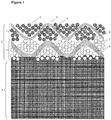
- FIG. 1 is a cross-sectional schematic view of an exemplary composite sliding member for explaining embodiments of the present invention.
- FIG. 1 is a cross-sectional schematic view of an exemplary composite sliding member for explaining embodiments of the present invention.
- FIG. 1 is a schematic view of an embodiment of double woven fabric prepared by using a multifilament for both of the fluororesin fiber and the heat resistant fiber. The schematic view is the same when the fibers used were spun yarn.
- the composite sliding member according to the present invention is a composite sliding member having a fiber woven fabric 3 integrated with the sliding surface of the resin member 4 which is the substrate.
- the fiber woven fabric 3 is a multilayer woven fabric comprising a front surface layer 1 serving as the sliding surface and a rear surface layer 2 serving as a surface to be adhered to the resin member.
- the multilayer woven fabric is a woven fabric produced by using two or more types of fibers to realize a structure with variable ratio of the fiber constituting the front surface layer to the fiber constituting the rear surface layer. Examples include multiple woven fabric such as double woven fabric comprising the front surface layer and the rear surface layer, and also, satin, twill, double-weft fabric, and double-warp fabric.
- the front surface layer 1 mainly comprises a fluororesin fiber 5 in view of improving the sliding property
- the rear surface layer 2 of the woven fabric mainly comprises a heat resistant fiber in view of improving the adhesion.
- the fact that the rear surface layer 2 mainly comprises the heat resistant fiber means that a relatively small number of the fluororesin fibers are present and exposed in the rear surface layer.
- the reduced exposure of the non-sticky fluororesin fibers enables improvement in the adhesion between the rear surface layer 2 and the resin member 4.
- the area proportion of the fluororesin fibers is preferably up to 50%, more preferably up to 25%.
- the heat resistant fiber 8 is located at a position adjacent to the resin member 4, and the heat resistant fiber 7 intersects at right angle with the heat resistant fiber 8. And the heat resistant fiber 6 is not adjacent to the resin member 4 since another heat resistant fiber 7 is present therebetween.
- the heat resistant fibers 6, 7, and 8 may be either in the form of a multifilament or a spun yarn, and these are respectively composed of several monofilaments.
- the "monofilament" as used herein is the minimum unit of the fiber forms, and the monofilament includes both the monofilament in the form of a long fiber each constituting the multifilament and the monofilament in the form of a short fiber each constituting the spun yarn.
- each monofilament constituting the multifilament is shown as a circular cross-section.
- the fluororesin fiber used in the present invention is preferably a polytetrafluoroethylene fiber.
- Exemplary materials constituting the polytetrafluoroethylene fiber include a homopolymer of tetrafluoroethylene and a copolymer wherein tetrafluoroethylene constitutes at least 90 mol % and preferably at least 95 mol % of the entire material, and in view of the sliding property, higher content of the tetrafluoroethylene unit is preferable, and the fluororesin fiber is preferably a homopolymer.
- Non-limiting examples of the monomer which can be copolymerized with the tetrafluoroethylene include fluorovinyl compounds such as trifluoroethylene, trifluorochloroethylene, tetrafluoropropylene, and hexafluoropropylene and vinyl compounds such as propylene, ethylene, isobutylene, styrene, and acrylonitrile.
- fluorovinyl compounds such as trifluoroethylene, trifluorochloroethylene, tetrafluoropropylene, and hexafluoropropylene
- vinyl compounds such as propylene, ethylene, isobutylene, styrene, and acrylonitrile.
- the preferred are fluorovinyl compounds, and the more preferred are those having high fluorine content in view of fiber friction properties.
- heat resistant fiber means a fiber which is less likely to undergo melting, softening, degradation, burning when exposed to the frictional heat generated during its use as the sliding member, the heat conducted when the sliding member slides on a high-temperature substance, or the heat generated when the apparatus including the sliding member is intentionally heated.
- Exemplary such heat resistant fibers include fibers constituted from a resin or an inorganic material having a melting point or a thermal degradation temperature of approximately 270°C or higher. Examples include polyparaphenylene terephthalamide, polymethaphenylene isophthalamide, glass, carbon, polyparaphenylene benzobisoxazole (PBO), polyphenylene sulfide (PPS), liquid crystal polymer (LCP) such as liquid crystal polyester.
- the fiber woven fabric 3 and the resin member 4 are firmly adhered with each other, and the degree of adhesion is affected by the state of the rear surface layer 2 as observed in any cross-section (vertical cross section) of the composite sliding member crossing the fiber woven fabric 3, the resin member 4, and their composite interface.
- effective adhesion will be realized when the resin constituting the resin member 4 is in close contact with the entire periphery, or at least a part, of the monofilaments of the rear surface layer 2.
- the monofilaments not in close contact with the resin also contribute to the strength of the rear surface layer when they are thermally fused with adjacent monofilaments, and in turn, such filaments also contribute for the improvement of the adhesion strength.
- the contact between the monofilaments changes from point contact to linear contact when observed in cross-section, and the interface disappears in the contact area and the so called “neck growth” takes place to form the neck having a low curvature.
- the monofilaments are referred to be "in close contact" when the monofilaments are thermally fused.
- R1 when the ratio of the number of the monofilaments in the heat resistant fiber A which is not in close contact with either the resin constituting the resin member nor the adjacent monofilaments to the total number of monofilaments constituting one heat resistant fiber A that is at a position adjacent to the resin member with no intervening other heat resistant fiber is designated R1, this R1 is preferably in the range of 0 to 70% in view of the effectiveness of the invention.
- R1 is in the range of 0 to 70%, and preferably 0 to 50% as described above.
- the monofilament not in close contact with the resin of the resin member is the monofilament wherein the resin is not in contact with the entire periphery, or a part thereof, of the monofilament.
- the monofilament is determined to be in close contact with the resin when at least a part of the monofilament periphery is observed to be in contact with the resin in the monofilament cross-section.
- the monofilament which is not in close contact with the adjacent monofilament is the monofilament which is not thermally fused with the adjacent monofilament. Not only the monofilaments which are not in contact with the adjacent monofilament but also the monofilaments which seem to be in contact with another monofilament but not thermally fused are also regarded to be not in close contact. Absence of the thermal fusion can be determined by the absence of the neck with slight curvature formed by the neck growth at the position of the contact or by the observation of interface between both monofilaments at the place of contact.
- R1 is greater than 70%, degree of the adhesion between the monofilament and the resin or degree of the fusion between the monofilaments will be insufficient, and hence, the adhesion between the fiber woven fabric and the resin member will be insufficient.
- R1 of up to 50% is favorable in view of the stronger adhesion.
- the adhesion is determined by the state of the close contact of the periphery of the monofilaments with the resin or the thermal fusion state between adjacent monofilaments.
- quantitative measurement of the state of the monofilaments after their integration may be difficult, and in the present invention, attempts are made to focus the non-integrated monofilaments, and excellent effects are thereby realized by confirming and controlling the proportion of the non-integrated monofilaments.
- the state of the close contact of the monofilament or the fiber which is the assembly of the monofilaments to the resin is influenced by the fiber type and weaving conditions of the fiber woven fabric as well as the resin type.
- the state of the close contact may also be controlled by the heating temperature, resin temperature, pressure conditions, and the like used in the thermal melting and molding of the resin.
- gaps between the monofilaments constituting each heat resistant fiber contribute for the maintenance of slidability, namely, durability by serving shelter spaces for accommodating the broken pieces of the fluororesin fibers in the front surface layer generated by the abrasion of the fluororesin fibers by the sliding force. Accordingly, it is also preferable to control the gaps between the monofilaments of each heat resistant fiber in view of the slidability. More specifically, the value of R2 measured by the procedure as described below is preferably controlled in the present invention.
- one heat resistant fiber B at a position not adjacent to the resin member due to the presence of other heat resistant fiber 7 is randomly selected from the heat resistant fibers.
- R2 in the cross-section of the heat resistant fiber B R2 is preferably in the range of 10 to 100% and R2 is preferably greater than R1.
- R2 is in such range, adhesion will be realized in the heat resistant fibers in the rear surface layer 2, and gaps will be reliably provided between the monofilaments of the heat resistant fibers at appropriate position, and as a consequence, slidability will be improved with elongated life. More preferably, R2 is in the range of 30 to 100% and R2 is greater than R1. The state may be different depending on the number of all monofilaments constituting the heat resistant fiber B and the monofilament diameter, and R2 of less than 10% results in the insufficiency of the gaps contributing for the maintenance of the slidability and durability, and R2 of at least 30% results reliable formation of the efficient gaps.
- the resin member 4 is the substrate of the composite sliding member, and accordingly, it should have the mechanical strength required for a structural member and should be moldable into a complicated shape required for incorporation and functioning in the apparatus, and it should be capable of impregnating into the gaps between the monofilaments of the fiber woven fabric to secure the adhesion.
- the resin member 4 preferably comprises a thermoplastic resin.
- the thermoplastic resin can be used for compression molding and injection molding after melting the resin with heat, and it is also capable of being impregnated into the gaps between the fibers in the rear surface layer 2 of the fiber woven fabric 3 and gaps between the monofilaments constituting the fibers for close contact with the monofilaments and adhesion. Of these, the most preferred is the injection molding due to high freedom in the shaping as the resin member 4.
- thermoplastic resins include vinyl chloride resin, polystyrene, ABS resin, polyethylene, polypropylene, polyamide resin, polycarbonate resin, polyesters such as polyethylene terephthalate (PET) and polybutylene terephthalate (PBT), polyphenylene sulfide (PPS), polyether ether ketone (PEEK), liquid crystal polymers such as liquid crystal polyester, amorphous polyallylate, polyetherimide, synthetic rubbers and elastomers such as thermoplastic polyurethane, butadiene rubber, nitrile rubber, neoprene, and polyester, and mixtures thereof.
- PET polyethylene terephthalate
- PBT polybutylene terephthalate
- PPS polyphenylene sulfide
- PEEK polyether ether ketone
- liquid crystal polymers such as liquid crystal polyester, amorphous polyallylate, polyetherimide, synthetic rubbers and elastomers such as thermoplastic polyurethane, butad
- the resin member 4 may preferably comprise a heat resistant thermoplastic resin since this member may experience a high temperature by the heat generated in its use as a sliding member or by an intentional heating.
- heat resistant thermoplastic resin as used herein means a thermoplastic resin having a melting point of approximately 270°C or higher, and such thermoplastic resin may be selected from PPS, PEEK, liquid crystal polymers (LCP) such as liquid crystal polyester, amorphous polyallylate, polyetherimide, and the like.
- the resin member 4 should also have moldability so that it can be molded into a molded article, for example, by melt molding such as injection molding. Accordingly, the thermoplastic resin is more preferably PPS or liquid crystal polyester.
- PPS resin is a material which has extremely high strength and rigidity as well as high abrasion resistance in addition to the heat resistance, and it is a material durable even under severe conditions since this resin also has chemical resistance and resistance to hydrolytic degradation.
- Liquid crystal polyester resin which is a liquid crystal polymer has good chemical resistance and impact strength in addition to the high heat resistance, and due to its excellent size stability, this material is highly suitable for use in high-precision parts requiring processing into complicated or intricate shapes.
- the material used for the heat resistant fiber mainly located in the rear surface layer 2 of the fiber woven fabric 3 is preferably the one suitable for use with the thermoplastic resin constituting the resin member 4, namely, the one having high affinity and compatibility for the thermoplastic resin constituting the resin member 4.
- the degree of the affinity and compatibility may be determined by the presence of the terminal group having high chemical affinity or by the structural similarity at the molecular level. For example, those having the same type of bond such as amide bond, ester bond, or sulfide bond may be determined to have a high compatibility.
- the material used for the heat resistant fiber is preferably a thermoplastic resin which is the same material as the thermoplastic resin used for the resin member 4.
- the term "same material” as used herein means that it contains the same thermoplastic resin as its main constituent while it may contain different sub-constituents depending on the steps, additives, starting materials, and the like when it is formed into a fiber or a woven fabric, or a resin or a molded article.
- both of the heat resistant fiber and the resin used for the resin member comprise a thermoplastic resin and they are the same material, sufficient adhesion will be realized between the heat resistant fiber and the resin of the resin member with sufficient affinity.
- the thermoplastic resin of the resin member 4 melts and impregnates in the rear surface layer 2 of the fiber woven fabric, the rear surface layer of the fiber woven fabric may also receive a thermal stress of similar conditions, and in such case, adjacent monofilaments are more likely to be integrated by thermal fusion. This contributes for the improvement of the adhesion.
- exemplary suitable heat resistant thermoplastic resins which can be commonly used for the heat resistant fiber and the resin member 4 include PPS resin and liquid crystal polyester resin.
- the low friction composite sliding member comprising the substrate resin sliding member integrated with the low friction fluororesin fiber woven fabric has the low friction properties and the heat resistance of the fiber woven fabric as well as the structural member properties and injection moldability of the substrate resin member. Accordingly the performance required for the sliding material used in the application of OA equipment is fully met, and such sliding member is suitable for use in the OA equipment application wherein mechanical and thermal processes are conducted in a compact apparatus. Of such OA equipment, the sliding member is most suitable for use as the sliding member in the step where pressure and heat are applied to the non-fixed toner image on a recording paper passing therethrough in an image forming apparatus such as photocopier and printer, or a toner fixer incorporated in such apparatus.
- the counter material was a hollow cylinder made of S45C having an outer diameter of 25.6 mm, an inner diameter of 20 mm, and a length of 15 mm having its surface polished with a sandpaper to the range of 0.8 ⁇ m ⁇ 0.1 Ra when measured by a surface roughness tester (SJ-201 manufactured by Mitsutoyo).
- test specimen was cut out of the composite sliding member sheet to a size of 30 mm x 30 mm x 3 mm. 3 specimens were prepared.
- the coefficient of friction was determined by calculating the coefficient of friction in the stable part of the sliding torque measurement, and the wear was determined by measuring weight before and after the test to calculate the weight loss, and calculating the average of the three specimens.
- the coefficient of friction was evaluated A when the coefficient of friction was 0.10 to 0.15, B when it was 0.16 to 0.20, C when it was 0.21 to 0.25, and D when it was 0.26 or higher or the woven fabric was worn and torn by the abrasion.
- the wear was evaluated A when the weight loss was up to 4.0 mg, B when it was 4.1 to 5.0 mg, C when it was 5.1 to 6.0 mg, and D when it was at least 6.1 mg.
- Table 1 The criteria are shown below Table 1.
- a plane weave double fabric was prepared by using a rapier weaver.
- a polytetrafluoroethylene (PTFE) fiber of 440 dtex, 60 filaments, twisting number of 300 t/m was used for both the warp and the weft
- a polyphenylene sulfide (PPS) fiber of 220 dtex, 50 filaments, and twisting number of 130 t/m was used for both the warp and the weft.
- the warp weaving density was 70 + 70 (fluororesin fiber woven fabric (warp) + PPS fiber woven fabric (warp) (warps/2.54 cm)), and weft weaving density was 60 + 60 (fluororesin fiber woven fabric (weft) + PPS fiber woven fabric (weft) (wefts/2.54 cm)).
- the fluororesin fiber woven fabric and the PPS fiber woven fabric were twined such that twining frequency of the warps of the fluororesin fiber woven fabric and the PPS fiber woven fabric was 0.2.
- the thus woven fabric was then scoured in a scouring tank at 80°C, and the fabric was set at 200°C.
- test specimens of the composite sliding member sheets were prepared by using an injection molding machine (J110AD-110H manufactured by THE JAPAN STEEL WORKS, LTD.) equipped with an injection molding mold capable of molding a sheet with the size of 100 mm x 150 mm x 3 mm by the procedure as described below.
- the fiber woven fabric was placed in the core (movable) of the mold like insert molding so that the rear surface of the fiber woven fabric faces toward the inside of the mold, and then, PPS resin was injected into the cavity to prepare a composite sliding member comprising the fiber woven fabric integrated with the resin sheet.
- the injection molding was conducted under the conditions at a cylinder temperature of 320°C, a mold temperature of 130°C, an injection pressure of 150 MPa, and an injection speed of 20 mm/sec.
- the PPS resin used was "TORELINA” (registered trademark) A604 manufactured by Toray.
- Example 1 The procedure of Example 1 was repeated except that the injection speed was changed to 5 mm/sec in the injection molding.
- Example 1 The procedure of Example 1 was repeated except that the injection speed was changed to 10 mm/sec in the injection molding.
- Example 1 The procedure of Example 1 was repeated except that the injection speed was changed to 30 mm/sec in the injection molding.
- a woven fabric was prepared under the weaving conditions the same as those of the procedure of Example 1 except that the weft weaving density of the fabric was changed from 60 + 60 (fluororesin fiber woven fabric (weft) + PPS fiber woven fabric (weft) (wefts/2.54 cm)) to 80 + 80 (fluororesin fiber woven fabric (weft) + PPS fiber woven fabric (weft) (wefts/2.54 cm)).
- the injection molding was conducted by repeating the procedure of Example 1 to produce the composite sliding member.
- Example 1 The procedure of Example 1 was repeated except that the thermoplastic resin for the resin member supplied to the injection molding was changed to liquid crystal polyester resin, and the injection molding conditions were changed to a cylinder temperature of 330°C and an injection pressure of 100 MPa.
- the liquid crystal polyester resin used was "SIVERAS” (registered trademark) LX70T35H manufactured by Toray.
- thermoplastic resin fiber constituting the rear surface layer of the woven fabric was changed to a polyethylene terephthalate (PET) fiber of 220 dtex, 48 filaments, and no twisting for both the warp and the weft.
- PET polyethylene terephthalate
- the thermoplastic resin used for the injection molding was changed to polybutylene terephthalate (PBT) resin, and the injection molding was conducted under the same conditions as those used in Example 1 except that the cylinder temperature was changed to 260°C to produce the composite sliding member.
- the polybutylene terephthalate (PBT) resin used was "TORAYCON” (registered trademark) 1101G-30 manufactured by Toray.
- Comparative Example 2 The procedure of Comparative Example 2 was repeated except that the injection speed was changed to 5 mm/sec in the injection molding.
- Example 5 while the type of the resin used for the resin member has been changed to liquid crystal polyester resin, the cylinder temperature has been optimized, and accordingly, the ratios R1 and R2 of the monofilaments not in close contact with the resin or the adjacent monofilaments are within the scope of the present invention.
- Comparative Example 1 While the type of materials used for the fiber woven fabric and the resin member as well as the conditions used for the injection molding were the same as those of Example 1, weft density in the weaving was increased, and as a consequence, R1 is outside the scope of the present invention.
- Comparative Examples 2 and 3 the PET fiber constituting the rear surface layer of the woven fabric is outside the scope of the heat resistant fiber of the present invention, and in Comparative Example 3, R1 is outside the scope of the present invention.
- the sliding materials of Examples 1 to 5 exhibited excellent adhesion between the resin member and the fiber woven fabric as well as low coefficient of friction and high durability with reduced abrasion.
- the sliding members prepared in Comparative Examples 2 and 3 are not suitable for the application of heat resistant sliding member since these members were prepared by using a PET fiber which is not a heat resistant fiber.
Landscapes
- Chemical & Material Sciences (AREA)
- Chemical Kinetics & Catalysis (AREA)
- General Chemical & Material Sciences (AREA)
- Oil, Petroleum & Natural Gas (AREA)
- Organic Chemistry (AREA)
- Engineering & Computer Science (AREA)
- Textile Engineering (AREA)
- Woven Fabrics (AREA)
- Laminated Bodies (AREA)
- Sliding-Contact Bearings (AREA)
- Fixing For Electrophotography (AREA)
- Reinforced Plastic Materials (AREA)
Abstract
Description
- The present invention relates to a composite sliding member having low friction property and a heat resistant composite sliding member prepared by incorporating such composite sliding member in OA equipment.
- Exemplary conventional sliding materials required to have a low friction include sliding members having a substrate with a surface layer having a fluororesin laminated or coated thereon and sliding members having a substrate and a fabric such as woven fabric, knitted fabric, or nonwoven fabric disposed thereon, the fabric being the one prepared by using a fluororesin fiber.
- However, the fluororesin laminate and coating were insufficient in the fluororesin film thickness, and they were also non-adherent, and therefore, the laminate and the coating had the drawback that they were likely to be peeled off the substrate.
- In the meanwhile, also disclosed is a technology wherein a fluororesin fiber fabric is used in combination with the sliding member, which is the substrate. For example, Patent Document 1 discloses a sliding member used as a pressure-applying low-friction sliding member in a toner fixer incorporated in an image forming apparatus such as photocopier or printer wherein a porous fluororesin woven fabric is used on the surface of the sliding member.
Patent Document 2 discloses a technology wherein a fabric containing a fluorine based fiber is mounted on the surface of the vibration-isolating rubber in an automobile stabilizer bar to thereby reduce the friction of the vibration-isolating rubber. - Another known production technology is integration of a woven fabric or a fiber material with a resin member although this technology is not for the sliding member. For example,
Patent Document 3 discloses a production of a laminate produced by injecting a thermoplastic resin on the rear surface of a knitted or woven fiber fabric or the like to form the substrate. -
- Patent Document 1: Japanese Unexamined Patent Publication (Kokai) No.
2010-164999 - Patent Document 2: Japanese Unexamined Patent Publication (Kokai) No.
2008-150724 - Patent Document 3: Japanese Unexamined Patent Publication (Kokai) No.
59-095126 - As described above in
Patent Documents 1 and 2, low friction sliding members wherein the surface of the substrate sliding member is covered with a fluororesin fabric have been disclosed. However, these members are insufficient in the adhesion and securing to the substrate due to the non-sticky nature of the fluorine fiber. - In Patent Document 1, two or more engagement holes are formed in the fluorine fiber woven fabric, and the substrate is provided with engagement means at positions corresponding to the engagement holes to thereby engage the fluorine fiber woven fabric to the surface of the sliding member. In
Patent Document 2, adhesion to the vibration-isolating rubber is improved by incorporation of thermally fusible fibers in the surface of the fabric containing the fluorine-based fibers on the surface opposite to the surface containing the fluorine-based fibers. - As described above, various procedures have been proposed to improve the adhesion in securing the inherently non-sticky fluorine fiber fabric to the surface of the substrate sliding member. However, these proposals have been insufficient in improving the adhesion for maintaining durability and abrasion resistance under the strong force applied during the sliding. There is also the problem of time, effort, and cost.
- In the meanwhile,
Patent Document 3 uses a thermoplastic resin for both of the fiber woven or knitted fabric (the surface) and the molding material (the substrate), and the substrate material is injected to the rear surface of the surface layer to form the substrate while the front surface layer is softened by the heating to realize the integration by thermal fusion. In this process, the firm adhesion is enabled by using the same material for both the front surface layer and the substrate. However, this is not a technology of providing a low friction material such as fluororesin fiber on the front surface layer in addition to the thermoplastic resin, and this is not realization of the low friction and the long life as a sliding member. - In view of the situation as described above, the object of the present invention is to provide a low friction composite sliding member exhibiting excellent adhesion property by integrating a resin sliding member (the substrate) and a low friction fiber woven fabric.
- In order to solve the problems as described above, the present invention has the following constitution.
-
- (1) A composite sliding member comprising a combination of a fiber woven fabric and a resin member, wherein the fiber woven fabric is a multilayer woven fabric having front surface layer serving as a sliding surface and rear surface layer adhered to the resin member, the front surface layer mainly comprising a fluororesin fiber and the rear surface layer mainly comprising a heat resistant fiber; wherein
when a cross-section of the composite sliding member crossing the fiber woven fabric, the resin member, and their composite interface is observed, one heat resistant fiber A of such heat resistant fiber at a position adjacent to the resin member with no intervening other fiber in this cross-section is observed, and ratio of number of monofilaments in the heat resistance fiber A not in close contact with the resin constituting the resin member or adjacent monofilaments in relation to number of all monofilaments constituting the heat resistance fiber A is designated R1, R1 is in the range of 0 to 70%. - (2) A composite sliding member according to (1) wherein, when a cross-section of the composite sliding member crossing the fiber woven fabric, the resin member, and their composite interface is observed, one heat resistant fiber B of such heat resistant fiber at a position intervened from being adjacent to the resin member by a perpendicular fiber in this cross-section is observed, and ratio of number of monofilaments in the heat resistance fiber B not in close contact with the resin continuing from the resin member or adjacent monofilaments in relation to number of all monofilaments constituting the heat resistance fiber B is designated R2, R2 is in the range of 10 to 100%, and R2 is greater than R1.
- (3) A composite sliding member according to (1) or (2) wherein the resin member comprises a thermoplastic resin having heat resistance.
- (4) A composite sliding member according to any one of (1) to (3) wherein the resin used in the heat resistance fiber and the resin used in the resin member both comprise a thermoplastic resin of the same material.
- (5) A composite sliding member according to (3) or (4) wherein the thermoplastic resin is a polyphenylene sulfide resin or a liquid crystal polyester resin.
- (6) A heat resistant composite sliding member for OA equipment wherein the composite sliding member of any one of (1) to (5) is used for the application of OA equipment. Advantageous Effect of the Invention
- The present invention provides a heat resistant low friction composite sliding member having long-term low friction, durability, and abrasion resistance by improving the adhesion through integration of the resin member (the substrate) and the multilayer woven fabric of a fluororesin fiber in an adequate form.
- [
FIG. 1] FIG. 1 is a cross-sectional schematic view of an exemplary composite sliding member for explaining embodiments of the present invention. - Next, embodiments of the present invention are described by referring to
FIG. 1. FIG. 1 is a cross-sectional schematic view of an exemplary composite sliding member for explaining embodiments of the present invention. -
FIG. 1 is a schematic view of an embodiment of double woven fabric prepared by using a multifilament for both of the fluororesin fiber and the heat resistant fiber. The schematic view is the same when the fibers used were spun yarn. - The composite sliding member according to the present invention is a composite sliding member having a
fiber woven fabric 3 integrated with the sliding surface of theresin member 4 which is the substrate. - The
fiber woven fabric 3 is a multilayer woven fabric comprising a front surface layer 1 serving as the sliding surface and arear surface layer 2 serving as a surface to be adhered to the resin member. The multilayer woven fabric is a woven fabric produced by using two or more types of fibers to realize a structure with variable ratio of the fiber constituting the front surface layer to the fiber constituting the rear surface layer. Examples include multiple woven fabric such as double woven fabric comprising the front surface layer and the rear surface layer, and also, satin, twill, double-weft fabric, and double-warp fabric. - In the multilayer woven fabric constituting the composite sliding member of the present invention, the front surface layer 1 mainly comprises a
fluororesin fiber 5 in view of improving the sliding property, and therear surface layer 2 of the woven fabric mainly comprises a heat resistant fiber in view of improving the adhesion. The fact that therear surface layer 2 mainly comprises the heat resistant fiber means that a relatively small number of the fluororesin fibers are present and exposed in the rear surface layer. The reduced exposure of the non-sticky fluororesin fibers enables improvement in the adhesion between therear surface layer 2 and theresin member 4. Of the fibers observable from the rear surface of the multilayer woven fabric, the area proportion of the fluororesin fibers is preferably up to 50%, more preferably up to 25%. - In
FIG.1 , the heatresistant fiber 8 is located at a position adjacent to theresin member 4, and the heatresistant fiber 7 intersects at right angle with the heatresistant fiber 8. And the heatresistant fiber 6 is not adjacent to theresin member 4 since another heatresistant fiber 7 is present therebetween. The heatresistant fibers FIG.1 , each monofilament constituting the multifilament is shown as a circular cross-section. - The fluororesin fiber used in the present invention is preferably a polytetrafluoroethylene fiber. Exemplary materials constituting the polytetrafluoroethylene fiber include a homopolymer of tetrafluoroethylene and a copolymer wherein tetrafluoroethylene constitutes at least 90 mol % and preferably at least 95 mol % of the entire material, and in view of the sliding property, higher content of the tetrafluoroethylene unit is preferable, and the fluororesin fiber is preferably a homopolymer.
- Non-limiting examples of the monomer which can be copolymerized with the tetrafluoroethylene include fluorovinyl compounds such as trifluoroethylene, trifluorochloroethylene, tetrafluoropropylene, and hexafluoropropylene and vinyl compounds such as propylene, ethylene, isobutylene, styrene, and acrylonitrile. Of these monomers, the preferred are fluorovinyl compounds, and the more preferred are those having high fluorine content in view of fiber friction properties.
- The "heat resistant fiber" as used herein means a fiber which is less likely to undergo melting, softening, degradation, burning when exposed to the frictional heat generated during its use as the sliding member, the heat conducted when the sliding member slides on a high-temperature substance, or the heat generated when the apparatus including the sliding member is intentionally heated. Exemplary such heat resistant fibers include fibers constituted from a resin or an inorganic material having a melting point or a thermal degradation temperature of approximately 270°C or higher. Examples include polyparaphenylene terephthalamide, polymethaphenylene isophthalamide, glass, carbon, polyparaphenylene benzobisoxazole (PBO), polyphenylene sulfide (PPS), liquid crystal polymer (LCP) such as liquid crystal polyester.
- In the composite sliding member of the present invention, the
fiber woven fabric 3 and theresin member 4 are firmly adhered with each other, and the degree of adhesion is affected by the state of therear surface layer 2 as observed in any cross-section (vertical cross section) of the composite sliding member crossing thefiber woven fabric 3, theresin member 4, and their composite interface. In other words, effective adhesion will be realized when the resin constituting theresin member 4 is in close contact with the entire periphery, or at least a part, of the monofilaments of therear surface layer 2. In addition, the monofilaments not in close contact with the resin also contribute to the strength of the rear surface layer when they are thermally fused with adjacent monofilaments, and in turn, such filaments also contribute for the improvement of the adhesion strength. When the monofilaments become thermally fused, the contact between the monofilaments changes from point contact to linear contact when observed in cross-section, and the interface disappears in the contact area and the so called "neck growth" takes place to form the neck having a low curvature. In the present invention, the monofilaments are referred to be "in close contact" when the monofilaments are thermally fused. - In the present invention, in the vertical cross-section as described above, when the ratio of the number of the monofilaments in the heat resistant fiber A which is not in close contact with either the resin constituting the resin member nor the adjacent monofilaments to the total number of monofilaments constituting one heat resistant fiber A that is at a position adjacent to the resin member with no intervening other heat resistant fiber is designated R1, this R1 is preferably in the range of 0 to 70% in view of the effectiveness of the invention.
- Next, measurement of the R1 is explained by referring to
FIG. 1 . First, of the heat resistant fibers, one heat resistant fiber A at a position adjacent to theresin member 4 with no intervening other heat resistant fiber 7 (for example, any one of the heatresistant fiber 8 inFIG. 1 ) is randomly selected. Of all monofilaments constituting the selected one heat resistant fiber A (multifilament) in the cross-section of such heat resistant fiber A, proportion (ratio) of the monofilaments not in close contact with the resin of theresin member 4 or the adjacent monofilaments is designated R1. In the present invention, R1 is in the range of 0 to 70%, and preferably 0 to 50% as described above. - The monofilament not in close contact with the resin of the resin member is the monofilament wherein the resin is not in contact with the entire periphery, or a part thereof, of the monofilament. In other words, the monofilament is determined to be in close contact with the resin when at least a part of the monofilament periphery is observed to be in contact with the resin in the monofilament cross-section.
- The monofilament which is not in close contact with the adjacent monofilament is the monofilament which is not thermally fused with the adjacent monofilament. Not only the monofilaments which are not in contact with the adjacent monofilament but also the monofilaments which seem to be in contact with another monofilament but not thermally fused are also regarded to be not in close contact. Absence of the thermal fusion can be determined by the absence of the neck with slight curvature formed by the neck growth at the position of the contact or by the observation of interface between both monofilaments at the place of contact.
- When R1 is greater than 70%, degree of the adhesion between the monofilament and the resin or degree of the fusion between the monofilaments will be insufficient, and hence, the adhesion between the fiber woven fabric and the resin member will be insufficient. R1 of up to 50% is favorable in view of the stronger adhesion.
- As described above, the adhesion is determined by the state of the close contact of the periphery of the monofilaments with the resin or the thermal fusion state between adjacent monofilaments. However, quantitative measurement of the state of the monofilaments after their integration may be difficult, and in the present invention, attempts are made to focus the non-integrated monofilaments, and excellent effects are thereby realized by confirming and controlling the proportion of the non-integrated monofilaments.
- The state of the close contact of the monofilament or the fiber which is the assembly of the monofilaments to the resin is influenced by the fiber type and weaving conditions of the fiber woven fabric as well as the resin type. The state of the close contact, however, may also be controlled by the heating temperature, resin temperature, pressure conditions, and the like used in the thermal melting and molding of the resin.
- In the meanwhile, gaps between the monofilaments constituting each heat resistant fiber contribute for the maintenance of slidability, namely, durability by serving shelter spaces for accommodating the broken pieces of the fluororesin fibers in the front surface layer generated by the abrasion of the fluororesin fibers by the sliding force. Accordingly, it is also preferable to control the gaps between the monofilaments of each heat resistant fiber in view of the slidability. More specifically, the value of R2 measured by the procedure as described below is preferably controlled in the present invention.
- First, one heat resistant fiber B at a position not adjacent to the resin member due to the presence of other heat resistant fiber 7 (for example, any one of the heat
resistant fibers 6 inFIG.1 ) is randomly selected from the heat resistant fibers. When the ratio of the number of monofilaments not in close contact with the resin continuing from the resin member or adjacent monofilaments to the number of all monofilaments constituting this one multifilament is designated R2 in the cross-section of the heat resistant fiber B, R2 is preferably in the range of 10 to 100% and R2 is preferably greater than R1. When R2 is in such range, adhesion will be realized in the heat resistant fibers in therear surface layer 2, and gaps will be reliably provided between the monofilaments of the heat resistant fibers at appropriate position, and as a consequence, slidability will be improved with elongated life. More preferably, R2 is in the range of 30 to 100% and R2 is greater than R1. The state may be different depending on the number of all monofilaments constituting the heat resistant fiber B and the monofilament diameter, and R2 of less than 10% results in the insufficiency of the gaps contributing for the maintenance of the slidability and durability, and R2 of at least 30% results reliable formation of the efficient gaps. - The
resin member 4 is the substrate of the composite sliding member, and accordingly, it should have the mechanical strength required for a structural member and should be moldable into a complicated shape required for incorporation and functioning in the apparatus, and it should be capable of impregnating into the gaps between the monofilaments of the fiber woven fabric to secure the adhesion. Accordingly, theresin member 4 preferably comprises a thermoplastic resin. The thermoplastic resin can be used for compression molding and injection molding after melting the resin with heat, and it is also capable of being impregnated into the gaps between the fibers in therear surface layer 2 of the fiber wovenfabric 3 and gaps between the monofilaments constituting the fibers for close contact with the monofilaments and adhesion. Of these, the most preferred is the injection molding due to high freedom in the shaping as theresin member 4. - Exemplary such thermoplastic resins include vinyl chloride resin, polystyrene, ABS resin, polyethylene, polypropylene, polyamide resin, polycarbonate resin, polyesters such as polyethylene terephthalate (PET) and polybutylene terephthalate (PBT), polyphenylene sulfide (PPS), polyether ether ketone (PEEK), liquid crystal polymers such as liquid crystal polyester, amorphous polyallylate, polyetherimide, synthetic rubbers and elastomers such as thermoplastic polyurethane, butadiene rubber, nitrile rubber, neoprene, and polyester, and mixtures thereof.
- The
resin member 4 may preferably comprise a heat resistant thermoplastic resin since this member may experience a high temperature by the heat generated in its use as a sliding member or by an intentional heating. The term "heat resistant thermoplastic resin" as used herein means a thermoplastic resin having a melting point of approximately 270°C or higher, and such thermoplastic resin may be selected from PPS, PEEK, liquid crystal polymers (LCP) such as liquid crystal polyester, amorphous polyallylate, polyetherimide, and the like. In addition to the heat resistance, theresin member 4 should also have moldability so that it can be molded into a molded article, for example, by melt molding such as injection molding. Accordingly, the thermoplastic resin is more preferably PPS or liquid crystal polyester. - PPS resin is a material which has extremely high strength and rigidity as well as high abrasion resistance in addition to the heat resistance, and it is a material durable even under severe conditions since this resin also has chemical resistance and resistance to hydrolytic degradation.
- Liquid crystal polyester resin which is a liquid crystal polymer has good chemical resistance and impact strength in addition to the high heat resistance, and due to its excellent size stability, this material is highly suitable for use in high-precision parts requiring processing into complicated or intricate shapes.
- The material used for the heat resistant fiber mainly located in the
rear surface layer 2 of the fiber wovenfabric 3 is preferably the one suitable for use with the thermoplastic resin constituting theresin member 4, namely, the one having high affinity and compatibility for the thermoplastic resin constituting theresin member 4. The degree of the affinity and compatibility may be determined by the presence of the terminal group having high chemical affinity or by the structural similarity at the molecular level. For example, those having the same type of bond such as amide bond, ester bond, or sulfide bond may be determined to have a high compatibility. - The material used for the heat resistant fiber is preferably a thermoplastic resin which is the same material as the thermoplastic resin used for the
resin member 4. The term "same material" as used herein means that it contains the same thermoplastic resin as its main constituent while it may contain different sub-constituents depending on the steps, additives, starting materials, and the like when it is formed into a fiber or a woven fabric, or a resin or a molded article. - When both of the heat resistant fiber and the resin used for the resin member comprise a thermoplastic resin and they are the same material, sufficient adhesion will be realized between the heat resistant fiber and the resin of the resin member with sufficient affinity. Also, when the thermoplastic resin of the
resin member 4 melts and impregnates in therear surface layer 2 of the fiber woven fabric, the rear surface layer of the fiber woven fabric may also receive a thermal stress of similar conditions, and in such case, adjacent monofilaments are more likely to be integrated by thermal fusion. This contributes for the improvement of the adhesion. - In the present invention, exemplary suitable heat resistant thermoplastic resins which can be commonly used for the heat resistant fiber and the
resin member 4 include PPS resin and liquid crystal polyester resin. - As described above, the low friction composite sliding member comprising the substrate resin sliding member integrated with the low friction fluororesin fiber woven fabric has the low friction properties and the heat resistance of the fiber woven fabric as well as the structural member properties and injection moldability of the substrate resin member. Accordingly the performance required for the sliding material used in the application of OA equipment is fully met, and such sliding member is suitable for use in the OA equipment application wherein mechanical and thermal processes are conducted in a compact apparatus. Of such OA equipment, the sliding member is most suitable for use as the sliding member in the step where pressure and heat are applied to the non-fixed toner image on a recording paper passing therethrough in an image forming apparatus such as photocopier and printer, or a toner fixer incorporated in such apparatus.
- Next, the Examples of the present invention are described with Comparative Examples.
- The properties used in the Examples are measured by the procedure as described below.
-
- (1) Ratio of the monofilaments not in close contact with the resin or the adjacent monofilaments in the vertical cross-section of the composite sliding member (R1, R2)
Test specimen were prepared to enable observation of areas around the cross-sections of the warp and weft heat resistant fibers in the resin member and the rear surface layer of the woven fabric in the vertical cross-sections obtained by cutting the composite sliding member sheet in the vertical direction and longitudinal direction of the woven fabric (cross-section of the composite sliding member crossing the fiber woven fabric, the resin member, and their composite interface). Pictures were taken by a scanning electron microscope (SEM).
In the pictures of the areas around the cross-sections of the warp and weft heat resistant fibers, one heat resistant fiber (A) is randomly selected at the location where the heat resistant fiber is adjacent to the resin member with no intervening heat resistant fiber, and number of monofilaments that are observed to be not in contact with the resin continuing from the resin member or the adjacent monofilaments in the heat resistant fiber (A) is counted, and this number is represented as a percentage in relation to the number of all monofilaments. Average is calculated for the percentages obtained in three fields (n=3) for each of the areas around the cross-sections of the warp and weft, and this value is used for R1.
In determining the presence of the close contact between the monofilament in the picture of monofilament cross-section, the monofilament is determined to be in close contact with the resin when at least a part of the periphery of the monofilament cross-section is in contact with the resin. For the close contact between the monofilaments, the monofilament is determined to be not in close contact with the adjacent monofilament when the presence of a neck having a curvature reduced by the neck growth cannot be confirmed or if an interface dividing adjacent monofilaments is observed at the contact part of the adjacent monofilaments even if adjacent monofilaments are in contact with each other.
The scanning electron microscope used was S-3500N manufactured by HITACHI, and the microscope was used under the conditions including a magnification of 200, resolution of 640 x 480, and a scanning speed of 80/100s.
In the pictures of the areas around the cross-sections of the warp and weft heat resistant fibers, one heat resistant fiber (B) is randomly selected at the location where the heat resistant fiber is not adjacent to the resin member with intervening perpendicular heat resistant fiber, and number of monofilaments that are observed to be not in contact with the resin continuing from the resin member or the adjacent monofilaments in the heat resistant fiber (B) is counted, and this number is represented as a percentage in relation to the number of all monofilaments. Average is calculated for the percentages obtained in three fields (n=3) for each of the areas around the cross-sections of the warp and weft, and this value is used for R2.
It is to be noted that confirmation of the number of all monofilaments in the heat resistant fiber may be difficult in the location where most of the monofilaments in one fiber are integrated with the resin or with another monofilament. In such case, measurement precision may be improved by observing a fiber which is the same as the heat resistant fiber to be observed and which is located sufficiently remote from the resin member allowing the observation of clear cross-sectional contour of each monofilament. - (2) Peel strength between the resin member and the fiber woven fabric
The measurement was conducted according to method B defined in JIS L1021-9:2007. The test specimen with the size of 50 mm x 150 mm x 3 mm was cut out of a flat sheet of the composite sliding member. 80 mm in length of the fiber woven fabric of 150 mm was preliminarily peeled off the resin member, and the peeled end of the fiber woven fabric and the resin member were gripped by the upper and lower chucks of a tensile tester.
Subsequently, the fiber woven fabric and the resin member were pulled apart at a constant speed of 100 mm/min to peel a length of 50 mm. The maximum load (N) in the peeling of 50 mm was recorded.
The peel strength may be different in longitudinal direction and vertical direction, and therefore, 3 specimens were prepared for each of the peeling in the longitudinal and vertical directions of the fiber woven fabric, and the average of the 6 specimen measurements was used for the peel strength. - (3) Coefficient of friction and wear (ring abrasion test)
The measurement was conducted according to JIS K7218: 1986 (Testing Methods for Sliding Wear Resistance of Plastics), method A. The ring abrasion tester used was model EFM-III-EN manufactured by ORIENTEC CORPORATION, and the test was conducted at a frictional load of 10 MPa and a frictional speed of 10 mm/sec to measure sliding torque to the frictional sliding distance of 100 m. - The counter material was a hollow cylinder made of S45C having an outer diameter of 25.6 mm, an inner diameter of 20 mm, and a length of 15 mm having its surface polished with a sandpaper to the range of 0.8 µm ± 0.1 Ra when measured by a surface roughness tester (SJ-201 manufactured by Mitsutoyo).
- The test specimen was cut out of the composite sliding member sheet to a size of 30 mm x 30 mm x 3 mm. 3 specimens were prepared.
- The coefficient of friction was determined by calculating the coefficient of friction in the stable part of the sliding torque measurement, and the wear was determined by measuring weight before and after the test to calculate the weight loss, and calculating the average of the three specimens. The coefficient of friction was evaluated A when the coefficient of friction was 0.10 to 0.15, B when it was 0.16 to 0.20, C when it was 0.21 to 0.25, and D when it was 0.26 or higher or the woven fabric was wore and torn by the abrasion. The wear was evaluated A when the weight loss was up to 4.0 mg, B when it was 4.1 to 5.0 mg, C when it was 5.1 to 6.0 mg, and D when it was at least 6.1 mg. The criteria are shown below Table 1.
- A plane weave double fabric was prepared by using a rapier weaver. For the fluororesin fiber constituting the front surface layer of the fiber woven fabric, a polytetrafluoroethylene (PTFE) fiber of 440 dtex, 60 filaments, twisting number of 300 t/m was used for both the warp and the weft, and for the thermoplastic resin fiber constituting the rear surface layer of the woven fabric, a polyphenylene sulfide (PPS) fiber of 220 dtex, 50 filaments, and twisting number of 130 t/m was used for both the warp and the weft. The warp weaving density was 70 + 70 (fluororesin fiber woven fabric (warp) + PPS fiber woven fabric (warp) (warps/2.54 cm)), and weft weaving density was 60 + 60 (fluororesin fiber woven fabric (weft) + PPS fiber woven fabric (weft) (wefts/2.54 cm)). The fluororesin fiber woven fabric and the PPS fiber woven fabric were twined such that twining frequency of the warps of the fluororesin fiber woven fabric and the PPS fiber woven fabric was 0.2. The thus woven fabric was then scoured in a scouring tank at 80°C, and the fabric was set at 200°C.
- Next, test specimens of the composite sliding member sheets were prepared by using an injection molding machine (J110AD-110H manufactured by THE JAPAN STEEL WORKS, LTD.) equipped with an injection molding mold capable of molding a sheet with the size of 100 mm x 150 mm x 3 mm by the procedure as described below. First, the fiber woven fabric was placed in the core (movable) of the mold like insert molding so that the rear surface of the fiber woven fabric faces toward the inside of the mold, and then, PPS resin was injected into the cavity to prepare a composite sliding member comprising the fiber woven fabric integrated with the resin sheet. The injection molding was conducted under the conditions at a cylinder temperature of 320°C, a mold temperature of 130°C, an injection pressure of 150 MPa, and an injection speed of 20 mm/sec.
- The PPS resin used was "TORELINA" (registered trademark) A604 manufactured by Toray.
- The procedure of Example 1 was repeated except that the injection speed was changed to 5 mm/sec in the injection molding.
- The procedure of Example 1 was repeated except that the injection speed was changed to 10 mm/sec in the injection molding.
- The procedure of Example 1 was repeated except that the injection speed was changed to 30 mm/sec in the injection molding.
- A woven fabric was prepared under the weaving conditions the same as those of the procedure of Example 1 except that the weft weaving density of the fabric was changed from 60 + 60 (fluororesin fiber woven fabric (weft) + PPS fiber woven fabric (weft) (wefts/2.54 cm)) to 80 + 80 (fluororesin fiber woven fabric (weft) + PPS fiber woven fabric (weft) (wefts/2.54 cm)). The injection molding was conducted by repeating the procedure of Example 1 to produce the composite sliding member.
- The procedure of Example 1 was repeated except that the thermoplastic resin for the resin member supplied to the injection molding was changed to liquid crystal polyester resin, and the injection molding conditions were changed to a cylinder temperature of 330°C and an injection pressure of 100 MPa.
- The liquid crystal polyester resin used was "SIVERAS" (registered trademark) LX70T35H manufactured by Toray.
- A woven fabric was prepared under the weaving conditions the same as those of the procedure of Example 1 except that the thermoplastic resin fiber constituting the rear surface layer of the woven fabric was changed to a polyethylene terephthalate (PET) fiber of 220 dtex, 48 filaments, and no twisting for both the warp and the weft. With regard to the resin member, the thermoplastic resin used for the injection molding was changed to polybutylene terephthalate (PBT) resin, and the injection molding was conducted under the same conditions as those used in Example 1 except that the cylinder temperature was changed to 260°C to produce the composite sliding member.
- The polybutylene terephthalate (PBT) resin used was "TORAYCON" (registered trademark) 1101G-30 manufactured by Toray.
- The procedure of Comparative Example 2 was repeated except that the injection speed was changed to 5 mm/sec in the injection molding.
- For the composite sliding members produced in Examples 1 to 5 and Comparative Examples 1 to 3, the results of the measurement of the ratios R1 and R2 of the monofilaments not in close contact with the resin or the adjacent monofilaments in the rear surface layer of the woven fabric, the peel strength test, and the ring abrasion test are shown in Table 1.
-

- As described above, the injection speed in the injection molding was changed in Examples 1 to 4, and this resulted in the change of the resin temperature in the filling of the resin in the mold, and degree of the resin impregnation in the gap between the fibers was altered, and this resulted in the change of the ratios R1 and R2 of the monofilaments not in close contact with the resin or the adjacent monofilaments. The R1 and R2, however, were still in the scope of the present invention. In Example 5, while the type of the resin used for the resin member has been changed to liquid crystal polyester resin, the cylinder temperature has been optimized, and accordingly, the ratios R1 and R2 of the monofilaments not in close contact with the resin or the adjacent monofilaments are within the scope of the present invention. On the other hand, in Comparative Example 1, while the type of materials used for the fiber woven fabric and the resin member as well as the conditions used for the injection molding were the same as those of Example 1, weft density in the weaving was increased, and as a consequence, R1 is outside the scope of the present invention. In Comparative Examples 2 and 3, the PET fiber constituting the rear surface layer of the woven fabric is outside the scope of the heat resistant fiber of the present invention, and in Comparative Example 3, R1 is outside the scope of the present invention.
- As a consequence, the sliding materials of Examples 1 to 5 exhibited excellent adhesion between the resin member and the fiber woven fabric as well as low coefficient of friction and high durability with reduced abrasion.
- On the other hand, the sliding materials of Comparative Examples 1 and 3 exhibited insufficient resin impregnation into the fiber woven fabric, and this resulted in the inferior adhesion and poor sliding property due to the peeling in the abrasion test.
- The sliding members prepared in Comparative Examples 2 and 3 are not suitable for the application of heat resistant sliding member since these members were prepared by using a PET fiber which is not a heat resistant fiber.
- It is to be noted that a picture at a magnification of 15 was taken for the area of 1 cm x 1cm in the rear surface of the fiber woven fabrics used in Examples 1 to 5 by using a microscope (VHX-2000 manufactured by Keyence). Of the fibers observed in the picture, the fluororesin fiber and the PPS fiber were colored in different colors to evaluate area ratio of the fluororesin fibers. The area ratio of the fluororesin fibers was 10% in all cases.
-
- 1:
- front surface layer
- 2:
- rear surface layer
- 3:
- fiber woven fabric
- 4:
- resin member
- 5:
- fluororesin fiber
- 6:
- heat resistant fiber
- 7:
- heat resistant fiber
- 8:
- heat resistant fiber
Claims (6)
- A composite sliding member comprising a combination of a fiber woven fabric and a resin member, wherein the fiber woven fabric is a multilayer woven fabric having front surface layer serving as a sliding surface and rear surface layer adhered to the resin member, the front surface layer mainly comprising a fluororesin fiber and the rear surface layer mainly comprising a heat resistant fiber; wherein
when a cross-section of the composite sliding member crossing the fiber woven fabric, the resin member, and their composite interface is observed, one heat resistant fiber A of such heat resistant fiber at a position adjacent to the resin member with no intervening other fiber in this cross-section is observed, and ratio of number of monofilaments in the heat resistant fiber A not in close contact with the resin constituting the resin member or adjacent monofilaments in relation to number of all monofilaments constituting the heat resistant fiber A is designated R1, R1 is in the range of 0 to 70%. - A composite sliding member according to claim 1 wherein, when a cross-section of the composite sliding member crossing the fiber woven fabric, the resin member, and their composite interface is observed, one heat resistant fiber B of such heat resistant fiber at a position intervened from being adjacent to the resin member by a perpendicular fiber in this cross-section is observed, and ratio of number of monofilaments in the heat resistant fiber B not in close contact with the resin continuing from the resin member or adjacent monofilaments in relation to number of all monofilaments constituting the heat resistant fiber B is designated R2, R2 is in the range of 10 to 100%, and R2 is greater than R1.
- A composite sliding member according to claim 1 or 2 wherein the resin member comprises a thermoplastic resin having heat resistance.
- A composite sliding member according to any one of claims 1 to 3 wherein the resin used in the heat resistant fiber and the resin used in the resin member both comprise a thermoplastic resin of the same material.
- A composite sliding member according to claim 3 or 4 wherein the thermoplastic resin is a polyphenylene sulfide resin or a liquid crystal polyester resin.
- A heat resistant composite sliding member for OA equipment wherein the composite sliding member of any one of claims 1 to 5 is used for the application of OA equipment.
Applications Claiming Priority (2)
| Application Number | Priority Date | Filing Date | Title |
|---|---|---|---|
| JP2014044720 | 2014-03-07 | ||
| PCT/JP2015/054838 WO2015133298A1 (en) | 2014-03-07 | 2015-02-20 | Composite sliding member and heat-resistant composite sliding member for oa equipment |
Publications (2)
| Publication Number | Publication Date |
|---|---|
| EP3115398A1 true EP3115398A1 (en) | 2017-01-11 |
| EP3115398A4 EP3115398A4 (en) | 2017-07-26 |
Family
ID=54055108
Family Applications (1)
| Application Number | Title | Priority Date | Filing Date |
|---|---|---|---|
| EP15758787.4A Withdrawn EP3115398A4 (en) | 2014-03-07 | 2015-02-20 | Composite sliding member and heat-resistant composite sliding member for oa equipment |
Country Status (5)
| Country | Link |
|---|---|
| US (1) | US9962912B2 (en) |
| EP (1) | EP3115398A4 (en) |
| JP (1) | JP6520707B2 (en) |
| CN (1) | CN106062048B (en) |
| WO (1) | WO2015133298A1 (en) |
Cited By (1)
| Publication number | Priority date | Publication date | Assignee | Title |
|---|---|---|---|---|
| WO2019188088A1 (en) * | 2018-03-26 | 2019-10-03 | Ricoh Company, Ltd. | Fixing device and image forming apparatus |
Families Citing this family (4)
| Publication number | Priority date | Publication date | Assignee | Title |
|---|---|---|---|---|
| US10647084B2 (en) | 2014-11-25 | 2020-05-12 | The Boeing Company | Multi-layer plies for improved composite performance |
| CN113166985B (en) * | 2018-12-26 | 2022-05-31 | 东丽株式会社 | Sliding fabric |
| JP7287102B2 (en) * | 2019-05-14 | 2023-06-06 | 株式会社リコー | Contact member, drying device, and printing device |
| JP2023028808A (en) * | 2021-08-20 | 2023-03-03 | シャープ株式会社 | Slide member, fixation device, and image formation device |
Family Cites Families (19)
| Publication number | Priority date | Publication date | Assignee | Title |
|---|---|---|---|---|
| JPS5995126A (en) | 1982-11-24 | 1984-06-01 | Aron Kasei Co Ltd | Method of manufacturing laminates |
| JPS6350488Y2 (en) | 1984-12-28 | 1988-12-26 | ||
| JPS6427547U (en) | 1987-08-10 | 1989-02-16 | ||
| US5726232A (en) * | 1995-12-21 | 1998-03-10 | Ntn Corporation | Heat resistant lubricative resin composition |
| US6476116B1 (en) * | 1999-09-22 | 2002-11-05 | Ntn Corporation | Resin compositions and precision sliding parts made of the same |
| JP4598351B2 (en) * | 2001-10-17 | 2010-12-15 | ジャパンゴアテックス株式会社 | Sheet-like sliding material |
| CN100412720C (en) * | 2003-12-19 | 2008-08-20 | 理光打印系统有限公司 | Fixing device and image forming device |
| JP2005220486A (en) * | 2004-02-06 | 2005-08-18 | Toray Ind Inc | Fluorofiber interwoven fabrics and composite materials |
| JP4882721B2 (en) * | 2006-12-15 | 2012-02-22 | 東レ株式会社 | Anti-vibration rubber material for vehicles |
| JP5353552B2 (en) * | 2009-08-19 | 2013-11-27 | 三菱電機ビルテクノサービス株式会社 | Handrail for man conveyor and handrail for man conveyor |
| JP5759239B2 (en) * | 2010-04-27 | 2015-08-05 | ミネベア株式会社 | Non-lubricated plain bearing with self-lubricating liner |
| JP4577456B2 (en) | 2010-05-06 | 2010-11-10 | 富士ゼロックス株式会社 | Fixing device and image forming apparatus for electrophotographic system |
| CN101880436B (en) * | 2010-07-05 | 2012-05-30 | 清华大学 | Resin composition and molded article thereof |
| CN103958608B (en) * | 2011-12-13 | 2016-08-17 | 大金工业株式会社 | Resin combination and products formed |
| WO2014024671A1 (en) * | 2012-08-06 | 2014-02-13 | ダイキン工業株式会社 | Resin composition and molded article |
| DE102013202121A1 (en) * | 2013-02-08 | 2014-08-14 | Ks Gleitlager Gmbh | Metal / plastic sliding bearing composite material and slide bearing element produced therefrom |
| CN105408422B (en) * | 2013-07-25 | 2018-03-27 | 大金工业株式会社 | Thermoplastic resin composition and products formed |
| JP5810142B2 (en) * | 2013-09-27 | 2015-11-11 | ユーエムジー・エービーエス株式会社 | Reinforced thermoplastic resin composition and molded article |
| JP6446916B2 (en) * | 2014-08-28 | 2019-01-09 | 富士ゼロックス株式会社 | Fixing member, fixing device, and image forming apparatus |
-
2015
- 2015-02-20 CN CN201580012580.9A patent/CN106062048B/en active Active
- 2015-02-20 WO PCT/JP2015/054838 patent/WO2015133298A1/en not_active Ceased
- 2015-02-20 US US15/123,835 patent/US9962912B2/en active Active
- 2015-02-20 JP JP2015515300A patent/JP6520707B2/en active Active
- 2015-02-20 EP EP15758787.4A patent/EP3115398A4/en not_active Withdrawn
Cited By (3)
| Publication number | Priority date | Publication date | Assignee | Title |
|---|---|---|---|---|
| WO2019188088A1 (en) * | 2018-03-26 | 2019-10-03 | Ricoh Company, Ltd. | Fixing device and image forming apparatus |
| JP2019168626A (en) * | 2018-03-26 | 2019-10-03 | 株式会社リコー | Fixing device and image forming apparatus |
| US11474461B2 (en) | 2018-03-26 | 2022-10-18 | Ricoh Company, Ltd. | Fixing device with nip forming member having guide portions |
Also Published As
| Publication number | Publication date |
|---|---|
| JP6520707B2 (en) | 2019-05-29 |
| CN106062048A (en) | 2016-10-26 |
| EP3115398A4 (en) | 2017-07-26 |
| WO2015133298A1 (en) | 2015-09-11 |
| JPWO2015133298A1 (en) | 2017-04-06 |
| US9962912B2 (en) | 2018-05-08 |
| CN106062048B (en) | 2019-03-12 |
| US20170008262A1 (en) | 2017-01-12 |
Similar Documents
| Publication | Publication Date | Title |
|---|---|---|
| US9962912B2 (en) | Composite sliding member and heat-resistant composite sliding member for OA equipment | |
| KR101644210B1 (en) | Sliding member and image-fixing device | |
| US10358750B2 (en) | Wear-resistant multilayer fabrics | |
| EP4079470B1 (en) | Fabric, and cable cover for robot arm | |
| KR20190095292A (en) | Process for preparing fibrous material preimpregnated with thermoplastic polymer in powder form | |
| EP3530785A1 (en) | Sliding fabric | |
| JP7129434B2 (en) | Fibrous tapes and composites containing said tapes | |
| KR102901304B1 (en) | Method for producing a fibrous material pre-impregnated with a thermoplastic polymer in a fluidized bed | |
| KR102778942B1 (en) | Folding Back | |
| WO2023171604A1 (en) | Fabric |
Legal Events
| Date | Code | Title | Description |
|---|---|---|---|
| PUAI | Public reference made under article 153(3) epc to a published international application that has entered the european phase |
Free format text: ORIGINAL CODE: 0009012 |
|
| STAA | Information on the status of an ep patent application or granted ep patent |
Free format text: STATUS: REQUEST FOR EXAMINATION WAS MADE |
|
| 17P | Request for examination filed |
Effective date: 20160823 |
|
| AK | Designated contracting states |
Kind code of ref document: A1 Designated state(s): AL AT BE BG CH CY CZ DE DK EE ES FI FR GB GR HR HU IE IS IT LI LT LU LV MC MK MT NL NO PL PT RO RS SE SI SK SM TR |
|
| AX | Request for extension of the european patent |
Extension state: BA ME |
|
| DAX | Request for extension of the european patent (deleted) | ||
| A4 | Supplementary search report drawn up and despatched |
Effective date: 20170626 |
|
| RIC1 | Information provided on ipc code assigned before grant |
Ipc: B32B 5/24 20060101ALI20170620BHEP Ipc: B32B 5/02 20060101AFI20170620BHEP Ipc: B32B 7/12 20060101ALI20170620BHEP Ipc: B32B 3/28 20060101ALI20170620BHEP Ipc: B32B 27/28 20060101ALI20170620BHEP Ipc: C08J 5/04 20060101ALI20170620BHEP Ipc: B32B 7/04 20060101ALI20170620BHEP Ipc: B32B 5/26 20060101ALI20170620BHEP Ipc: B32B 27/36 20060101ALI20170620BHEP Ipc: B32B 5/12 20060101ALI20170620BHEP Ipc: B32B 27/12 20060101ALI20170620BHEP |
|
| GRAP | Despatch of communication of intention to grant a patent |
Free format text: ORIGINAL CODE: EPIDOSNIGR1 |
|
| STAA | Information on the status of an ep patent application or granted ep patent |
Free format text: STATUS: GRANT OF PATENT IS INTENDED |
|
| INTG | Intention to grant announced |
Effective date: 20200810 |
|
| STAA | Information on the status of an ep patent application or granted ep patent |
Free format text: STATUS: THE APPLICATION IS DEEMED TO BE WITHDRAWN |
|
| 18D | Application deemed to be withdrawn |
Effective date: 20201222 |