EP3115323A1 - Sheet conveyance apparatus - Google Patents
Sheet conveyance apparatus Download PDFInfo
- Publication number
- EP3115323A1 EP3115323A1 EP16175181.3A EP16175181A EP3115323A1 EP 3115323 A1 EP3115323 A1 EP 3115323A1 EP 16175181 A EP16175181 A EP 16175181A EP 3115323 A1 EP3115323 A1 EP 3115323A1
- Authority
- EP
- European Patent Office
- Prior art keywords
- rotary member
- roller
- conveyance roller
- rotation axis
- sheet
- Prior art date
- Legal status (The legal status is an assumption and is not a legal conclusion. Google has not performed a legal analysis and makes no representation as to the accuracy of the status listed.)
- Granted
Links
Images






Classifications
-
- B—PERFORMING OPERATIONS; TRANSPORTING
- B65—CONVEYING; PACKING; STORING; HANDLING THIN OR FILAMENTARY MATERIAL
- B65H—HANDLING THIN OR FILAMENTARY MATERIAL, e.g. SHEETS, WEBS, CABLES
- B65H5/00—Feeding articles separated from piles; Feeding articles to machines
- B65H5/06—Feeding articles separated from piles; Feeding articles to machines by rollers or balls, e.g. between rollers
- B65H5/062—Feeding articles separated from piles; Feeding articles to machines by rollers or balls, e.g. between rollers between rollers or balls
-
- B—PERFORMING OPERATIONS; TRANSPORTING
- B65—CONVEYING; PACKING; STORING; HANDLING THIN OR FILAMENTARY MATERIAL
- B65H—HANDLING THIN OR FILAMENTARY MATERIAL, e.g. SHEETS, WEBS, CABLES
- B65H29/00—Delivering or advancing articles from machines; Advancing articles to or into piles
- B65H29/20—Delivering or advancing articles from machines; Advancing articles to or into piles by contact with rotating friction members, e.g. rollers, brushes, or cylinders
-
- B—PERFORMING OPERATIONS; TRANSPORTING
- B65—CONVEYING; PACKING; STORING; HANDLING THIN OR FILAMENTARY MATERIAL
- B65H—HANDLING THIN OR FILAMENTARY MATERIAL, e.g. SHEETS, WEBS, CABLES
- B65H29/00—Delivering or advancing articles from machines; Advancing articles to or into piles
- B65H29/12—Delivering or advancing articles from machines; Advancing articles to or into piles by means of the nip between two, or between two sets of, moving tapes or bands or rollers
- B65H29/125—Delivering or advancing articles from machines; Advancing articles to or into piles by means of the nip between two, or between two sets of, moving tapes or bands or rollers between two sets of rollers
-
- B—PERFORMING OPERATIONS; TRANSPORTING
- B65—CONVEYING; PACKING; STORING; HANDLING THIN OR FILAMENTARY MATERIAL
- B65H—HANDLING THIN OR FILAMENTARY MATERIAL, e.g. SHEETS, WEBS, CABLES
- B65H29/00—Delivering or advancing articles from machines; Advancing articles to or into piles
- B65H29/12—Delivering or advancing articles from machines; Advancing articles to or into piles by means of the nip between two, or between two sets of, moving tapes or bands or rollers
- B65H29/14—Delivering or advancing articles from machines; Advancing articles to or into piles by means of the nip between two, or between two sets of, moving tapes or bands or rollers and introducing into a pile
-
- B—PERFORMING OPERATIONS; TRANSPORTING
- B65—CONVEYING; PACKING; STORING; HANDLING THIN OR FILAMENTARY MATERIAL
- B65H—HANDLING THIN OR FILAMENTARY MATERIAL, e.g. SHEETS, WEBS, CABLES
- B65H29/00—Delivering or advancing articles from machines; Advancing articles to or into piles
- B65H29/52—Stationary guides or smoothers
-
- G—PHYSICS
- G03—PHOTOGRAPHY; CINEMATOGRAPHY; ANALOGOUS TECHNIQUES USING WAVES OTHER THAN OPTICAL WAVES; ELECTROGRAPHY; HOLOGRAPHY
- G03G—ELECTROGRAPHY; ELECTROPHOTOGRAPHY; MAGNETOGRAPHY
- G03G15/00—Apparatus for electrographic processes using a charge pattern
- G03G15/65—Apparatus which relate to the handling of copy material
- G03G15/6529—Transporting
-
- G—PHYSICS
- G03—PHOTOGRAPHY; CINEMATOGRAPHY; ANALOGOUS TECHNIQUES USING WAVES OTHER THAN OPTICAL WAVES; ELECTROGRAPHY; HOLOGRAPHY
- G03G—ELECTROGRAPHY; ELECTROPHOTOGRAPHY; MAGNETOGRAPHY
- G03G15/00—Apparatus for electrographic processes using a charge pattern
- G03G15/65—Apparatus which relate to the handling of copy material
- G03G15/6555—Handling of sheet copy material taking place in a specific part of the copy material feeding path
- G03G15/6573—Feeding path after the fixing point and up to the discharge tray or the finisher, e.g. special treatment of copy material to compensate for effects from the fixing
- G03G15/6576—Decurling of sheet material
-
- G—PHYSICS
- G06—COMPUTING OR CALCULATING; COUNTING
- G06K—GRAPHICAL DATA READING; PRESENTATION OF DATA; RECORD CARRIERS; HANDLING RECORD CARRIERS
- G06K15/00—Arrangements for producing a permanent visual presentation of the output data, e.g. computer output printers
- G06K15/02—Arrangements for producing a permanent visual presentation of the output data, e.g. computer output printers using printers
- G06K15/12—Arrangements for producing a permanent visual presentation of the output data, e.g. computer output printers using printers by photographic printing, e.g. by laser printers
-
- H—ELECTRICITY
- H04—ELECTRIC COMMUNICATION TECHNIQUE
- H04N—PICTORIAL COMMUNICATION, e.g. TELEVISION
- H04N1/00—Scanning, transmission or reproduction of documents or the like, e.g. facsimile transmission; Details thereof
- H04N1/00567—Handling of original or reproduction media, e.g. cutting, separating, stacking
- H04N1/0057—Conveying sheets before or after scanning
-
- H—ELECTRICITY
- H04—ELECTRIC COMMUNICATION TECHNIQUE
- H04N—PICTORIAL COMMUNICATION, e.g. TELEVISION
- H04N1/00—Scanning, transmission or reproduction of documents or the like, e.g. facsimile transmission; Details thereof
- H04N1/04—Scanning arrangements, i.e. arrangements for the displacement of active reading or reproducing elements relative to the original or reproducing medium, or vice versa
- H04N1/06—Scanning arrangements, i.e. arrangements for the displacement of active reading or reproducing elements relative to the original or reproducing medium, or vice versa using cylindrical picture-bearing surfaces, i.e. scanning a main-scanning line substantially perpendicular to the axis and lying in a curved cylindrical surface
-
- B—PERFORMING OPERATIONS; TRANSPORTING
- B65—CONVEYING; PACKING; STORING; HANDLING THIN OR FILAMENTARY MATERIAL
- B65H—HANDLING THIN OR FILAMENTARY MATERIAL, e.g. SHEETS, WEBS, CABLES
- B65H2301/00—Handling processes for sheets or webs
- B65H2301/50—Auxiliary process performed during handling process
- B65H2301/51—Modifying a characteristic of handled material
- B65H2301/512—Changing form of handled material
- B65H2301/5125—Restoring form
- B65H2301/51256—Removing waviness or curl, smoothing
- B65H2301/512565—Removing waviness or curl, smoothing involving tri-roller arrangement
-
- B—PERFORMING OPERATIONS; TRANSPORTING
- B65—CONVEYING; PACKING; STORING; HANDLING THIN OR FILAMENTARY MATERIAL
- B65H—HANDLING THIN OR FILAMENTARY MATERIAL, e.g. SHEETS, WEBS, CABLES
- B65H2404/00—Parts for transporting or guiding the handled material
- B65H2404/10—Rollers
- B65H2404/14—Roller pairs
- B65H2404/143—Roller pairs driving roller and idler roller arrangement
- B65H2404/1431—Roller pairs driving roller and idler roller arrangement idler roller details
-
- B—PERFORMING OPERATIONS; TRANSPORTING
- B65—CONVEYING; PACKING; STORING; HANDLING THIN OR FILAMENTARY MATERIAL
- B65H—HANDLING THIN OR FILAMENTARY MATERIAL, e.g. SHEETS, WEBS, CABLES
- B65H2404/00—Parts for transporting or guiding the handled material
- B65H2404/10—Rollers
- B65H2404/15—Roller assembly, particular roller arrangement
-
- B—PERFORMING OPERATIONS; TRANSPORTING
- B65—CONVEYING; PACKING; STORING; HANDLING THIN OR FILAMENTARY MATERIAL
- B65H—HANDLING THIN OR FILAMENTARY MATERIAL, e.g. SHEETS, WEBS, CABLES
- B65H2404/00—Parts for transporting or guiding the handled material
- B65H2404/10—Rollers
- B65H2404/16—Details of driving
- B65H2404/161—Means for driving a roller parallely to its axis of rotation, e.g. during its rotation
-
- B—PERFORMING OPERATIONS; TRANSPORTING
- B65—CONVEYING; PACKING; STORING; HANDLING THIN OR FILAMENTARY MATERIAL
- B65H—HANDLING THIN OR FILAMENTARY MATERIAL, e.g. SHEETS, WEBS, CABLES
- B65H2404/00—Parts for transporting or guiding the handled material
- B65H2404/10—Rollers
- B65H2404/17—Details of bearings
- B65H2404/172—Details of bearings tilting
-
- B—PERFORMING OPERATIONS; TRANSPORTING
- B65—CONVEYING; PACKING; STORING; HANDLING THIN OR FILAMENTARY MATERIAL
- B65H—HANDLING THIN OR FILAMENTARY MATERIAL, e.g. SHEETS, WEBS, CABLES
- B65H2801/00—Application field
- B65H2801/03—Image reproduction devices
- B65H2801/06—Office-type machines, e.g. photocopiers
-
- G—PHYSICS
- G03—PHOTOGRAPHY; CINEMATOGRAPHY; ANALOGOUS TECHNIQUES USING WAVES OTHER THAN OPTICAL WAVES; ELECTROGRAPHY; HOLOGRAPHY
- G03G—ELECTROGRAPHY; ELECTROPHOTOGRAPHY; MAGNETOGRAPHY
- G03G15/00—Apparatus for electrographic processes using a charge pattern
- G03G15/65—Apparatus which relate to the handling of copy material
- G03G15/6552—Means for discharging uncollated sheet copy material, e.g. discharging rollers, exit trays
-
- G—PHYSICS
- G03—PHOTOGRAPHY; CINEMATOGRAPHY; ANALOGOUS TECHNIQUES USING WAVES OTHER THAN OPTICAL WAVES; ELECTROGRAPHY; HOLOGRAPHY
- G03G—ELECTROGRAPHY; ELECTROPHOTOGRAPHY; MAGNETOGRAPHY
- G03G2215/00—Apparatus for electrophotographic processes
- G03G2215/00362—Apparatus for electrophotographic processes relating to the copy medium handling
- G03G2215/00535—Stable handling of copy medium
- G03G2215/00679—Conveying means details, e.g. roller
Definitions
- the present invention relates to a sheet conveyance apparatus conveying sheets.
- Japanese unexamined patent application publication No. 2007-145452 proposes a sheet conveyance apparatus having a conveyance roller and two driven rollers that contact the conveyance roller, capable of conveying a sheet while straightening the curl of the sheet.
- the two driven rollers are supported by a single holder such that the rotation axes of the rollers are parallel.
- Japanese unexamined patent application publication No. 2010-195544 discloses a configuration where driven rollers are inclined with respect to a conveyance roller so as to prevent semi-melted toner from attaching to the driven rollers and causing image defects, in a case where the sheet conveyance apparatus is arranged close to a fixing unit.
- the present invention in its first aspect provides a sheet conveyance apparatus as specified in claim 1.
- the present invention in its first aspect provides a sheet conveyance apparatus as specified in claim 2.
- the present invention in its first aspect provides a sheet conveyance apparatus as specified in claim 3.
- a printer 100 i.e., image forming apparatus, according to the first embodiment is an electro-photographic laser beam printer. As illustrated in FIG. 1 , the printer 100 includes a sheet feeding cassette 1 capable of being inserted to and drawn from a printer main body 100A, an image forming unit 50 forming an image on a sheet fed from the sheet feeding cassette 1, a fixing unit 60, and a sheet discharge portion 70.
- the image forming unit 50 includes a cartridge 5 having a photosensitive drum 6, i.e., an image bearing member, a laser scanner 8, and a transfer roller 7.
- the laser scanner 8 irradiates a laser beam 9 toward the photosensitive drum 6 based on the entered image information.
- the photosensitive drum 6 is charged in advance by a charging roller not shown, and an electrostatic latent image is formed on the photosensitive drum 6 by irradiating the laser beam 9. Thereafter, an electrostatic latent image is developed by a developing roller not shown, and a toner image is formed on the photosensitive drum 6.
- a sheet S supported on the sheet feeding cassette 1 is sent out by a feeding roller 2.
- the sheet S is separated one by one via a separation unit not shown.
- the sheet S is conveyed via an intermediate transfer roller 3 and a conveyance idler roller 4 toward the transfer roller 7.
- the transfer roller 7, i.e., transfer unit transfers a toner image formed on the photosensitive drum 6 to the sheet S by having a transfer bias applied thereto.
- the sheet S having the toner image transferred from the transfer roller 7 is heated and pressed by the fixing unit 60 composed of a heating roller 10 and a pressure roller 11, and the toner image is fixed. Then, the sheet S is discharged onto a discharge tray 30 by the sheet discharge portion 70 arranged downstream of the fixing unit in a sheet conveyance direction.
- the sheet discharge portion 70 includes a discharge upper guide 16 and a discharge lower guide 18 constituting a discharge conveyance path 31 (refer to FIG. 3 ), and a drive shaft 12a supported rotatably by bearings 17 and 17 press-fit to the discharge upper guide 16. Further, the sheet discharge portion 70 includes a first sheet conveyance unit 80A, i.e., sheet conveyance apparatus, and a second sheet conveyance unit 80B arranged abreast in a width direction orthogonal to the sheet conveyance direction.
- first sheet conveyance unit 80A i.e., sheet conveyance apparatus
- a second sheet conveyance unit 80B arranged abreast in a width direction orthogonal to the sheet conveyance direction.
- the first sheet conveyance unit 80A and the second sheet conveyance unit 80B are disposed symmetrically with respect to a center line in the width direction of the discharge conveyance path 31, and in the present embodiment, only the configuration of the first sheet conveyance unit 80A is described, and the configuration of the second sheet conveyance unit 80B will be omitted.
- the first sheet conveyance unit 80A includes a discharge roller 12, i.e., conveyance roller, fixed to a drive shaft 12a, i.e., rotation shaft, and a first idler roller 13c, i. e., first rotary member, driven by the discharge roller 12. Further, the first sheet conveyance unit 80A includes a second idler roller 14c, i.e., second rotary member, arranged downstream in the sheet conveyance direction of the first idler roller 13c, and driven by the discharge roller 12.
- the first sheet conveyance unit 80A includes, in a rotation shaft direction of the discharge roller 12, a first rotation shaft 13, i.e., first shaft portion, extending from both ends of the first idler roller 13c, a second rotation shaft 14, i.e., second shaft portion, extending from both ends of the second idler roller 14c, and a holding member 15, i.e., holder, rotatably supporting the first rotation shaft 13 and the second rotation shaft 14.
- the holding member 15 includes a first side wall 15a, i.e., first supporting portion, and a second side wall 15b, i.e., second supporting portion, disposed in parallel with the first side wall 15a.
- the first side wall 15a includes supporting portions 1513a and 1514a respectively rotatably supporting one end portion 13a of the first rotation shaft 13 and one end portion 14a of the second rotation shaft 14 arranged on the same side as the one end portion 13a.
- the second side wall 15b includes supporting portions 1513b and 1514b respectively rotatably supporting the other end portion 13b of the first rotation shaft 13 and the other end portion 14b of the second rotation shaft 14 arranged on the same side as the other end portion 13b.
- a virtual line L13 passing the supporting portions 1513a and 1513b is not parallel with a virtual line m14 passing a supporting portion 1514a and a supporting portion 1514b.
- FIG. 12B illustrates the holding member 15 viewed from a direction perpendicular to the first side wall 15a.
- the supporting portions 1513a and 1513b are arranged coaxially, whereas the supporting portions 1514a and 1514b are arranged non-coaxially.
- the supporting portions 1513a and 1513b are arranged at positions where the center portions are mutually overlapped, whereas the supporting portions 1514a and 1514b are arranged at positions where the center portions are not overlapped.
- the holding member 15 is designed such that the virtual line L13 is inclined with respect to the drive shaft 12a of the discharge roller 12.
- the holding member 15 is attached movably in a substantially vertical direction with respect to the discharge lower guide 18, and a spring 19 is arranged in a compressed manner between the discharge lower guide 18 and the holding member 15.
- the spring 19 biases the first idler roller 13c and the second idler roller 14c via the holding member 15 to be in pressure contact with the discharge roller 12. Further, the spring 19 is arranged such that the first idler roller 13c and the second idler roller 14c press a substantially center position in an axial direction of the discharge roller 12.
- a control unit not shown is provided in the printer main body 100A, and the drive shaft 12a is rotated by the control unit driving a drive source not shown.
- the drive shaft 12a rotates, the discharge roller 12 fixed to the drive shaft 12a rotates, and along with the rotation of the discharge roller 12, the first and second idler rollers 13c and 14c are driven to rotate.
- FIG. 5 is a side view of the discharge roller 12, the first idler roller 13c and the second idler roller 14c seen from a rotational axis line L1 of the discharge roller 12.
- FIG. 7 is a view seen from the direction of arrow A of FIGs. 5 and 6
- FIG. 8 is a view seen from the direction of arrow B of FIGs. 5 and 6 .
- the direction of arrow A is a direction perpendicular to a contact surface F1 between the discharge roller 12 and the first idler roller 13c
- the direction of arrow B is a direction perpendicular to a contact surface F2 between the discharge roller 12 and the second idler roller 14c.
- the first idler roller 13c is arranged such that the first rotation shaft 13 is inclined with respect to the rotational axis line L1 of the discharge roller 12.
- a rotational axis line L2 of the first idler roller 13c is inclined for angle ⁇ with respect to the rotational axis line L1 of the discharge roller 12.
- the second idler roller 14c is arranged such that the second rotation shaft 14 is inclined with respect to the rotational axis line L1 of the discharge roller 12 and the first rotation shaft 13.
- a rotational axis line L3 of the second idler roller 14c is inclined for angle ⁇ with respect to the rotational axis line L1 of the discharge roller 12.
- the inclination angles of the rotational axis lines L2 and L3 with respect to the rotational axis line L1 are the same angle ⁇ , but the angles can differ as long as the transfer of the sheet S is not hindered.
- the inclination of the first idler roller 13c and the second idler roller 14c are set in accordance with the positions of the supporting portions 1513a, 1513b, 1514a and 1514b of the holding member 15.
- the angle ⁇ should preferably be 1 degree or greater and 3 degrees or smaller.
- a plane parallel to the rotational axis line L1 of the discharge roller 12 and including the contact surfaces F1 and F2 is defined as a reference plane P.
- the first idler roller 13c and the second idler roller 14c are arranged to be inclined toward a same direction with respect to a width direction when viewed from a direction orthogonal to the reference plane P.
- the one end portion 13a positioned upstream in the sheet conveyance direction of the first rotation shaft 13 is arranged closer to the reference plane P than to the other end portion 13b positioned downstream.
- the one end portion 14a positioned upstream in the sheet conveyance direction of the second rotation shaft 14 is arranged farther from the reference plane P than the other end portion 14b positioned downstream.
- the first idler roller 13c and the second idler roller 14c are respectively independently inclined with respect to the discharge roller 12. Thereby, the first idler roller 13c and the second idler roller 14c are in contact at a center position in the width direction with the discharge roller 12. In other words, the first idler roller 13c and the second idler roller 14c contact the discharge roller 12 symmetrically with the center position in the width direction set as reference, such that the sheet S can be conveyed stably. Further, damages such as creases of the sheet can be reduced. Furthermore, the present arrangement prevents toner from attaching to the first and second idler rollers 13c and 14c, and to straighten the curls of the sheet.
- FIG. 13A is a view illustrating the discharge roller 12, the first idler roller 13c and the second idler roller 14c from the direction of the rotation axis of the discharge roller 12.
- one end face 13cF, i.e., one end, of the first idler roller 13c is illustrated by a solid line
- the other end face 13cB, i.e., the other end is illustrated by a dashed line.
- a center of one end face 13cF of the first idler roller 13c is referred to as C1
- a center of the other end face 13cB is referred to as C1' .
- FIGs. 13B and 13C are perspective views of the first idler roller 13c and the second idler roller 14c.
- a sheet is conveyed by a nip portion N2, i.e., second nip portion, formed by the discharge roller 12 being in contact with the second idler roller 14c.
- a conveyance direction D2 i.e., second conveyance direction, of a sheet at the nip portion N2 is a direction perpendicular to a line passing a center of the rotation shaft direction of the second idler roller 14c, i.e., center of a line segment connecting C2 and C2', and a center of rotation of the discharge roller 12, when seen from the rotation shaft direction of the discharge roller 12.
- a rotation shaft of the first idler roller 13c is inclined in the following manner with respect to the rotation shaft of the discharge roller 12.
- the center C1' of the other end face 13cB of the rotation shaft direction of the first idler roller 13c is shifted downstream with respect to the center C1 of one end face 13cF of the sheet conveyance direction D1 of the nip portion N1.
- the rotation shaft of the second idler roller 14c is inclined in the following manner with respect to the rotation shaft of the discharge roller 12.
- FIG. 14A is a view illustrating the discharge roller 12, the first idler roller 13c and the second idler roller 14c from the rotation shaft direction of the discharge roller 12.
- one end face 13cF of the first idler roller 13c is illustrated by a solid line
- the other end face 13cB is illustrated by a dashed line.
- the center of one end face 13cF of the first idler roller 13c is referred to as C1
- the center of the other end face 13cB is referred to as C1'.
- first area A1 and a second area A2 areas divided by a virtual line v12 passing the centers C1 and C2 are referred to as a first area A1 and a second area A2.
- the first idler roller 13c and the second idler roller 14c are respectively inclined with respect to the discharge roller 12 such that the center C1' of the other end face 13cB of the first idler roller 13c is positioned within the first area A1 and the center C2' of the other end face 14cB of the second idler roller 14c is positioned within the second area A2.
- the first and second sheet conveyance units 80A and 80B are arranged symmetrically with respect to a center line, i.e., a center portion of the discharge roller 12 in the rotation axis direction thereof, in the width direction of the discharge conveyance path 31.
- the conveyance directions of the first and second idler rollers 13c and 14c of the first and second sheet conveyance units 80A and 80B are respectively directed outward by predetermined angles with respect to the sheet conveyance direction. In other words, the sheet S will be pulled outward in the width direction while the sheet S is being conveyed by the sheet discharge portion 70, so that skew feeding and forming of creases on the sheet S can be prevented.
- the sheet discharge portion 70 has a pair of sheet conveyance units 80A and 80B, but the present invention is not restricted to this configuration, and two or more pairs of sheet conveyance units arranged in parallel in the width direction can also be adopted.
- the second embodiment has changed the configuration of the first and second idler rollers 13c and 14c of the first embodiment, and the configurations similar to the first embodiment are either not illustrated or assigned with the same reference numbers.
- a first idler roller 23 includes a disk-shaped first disk portion 23a and second disk portion 23b arranged in parallel in the axial direction, and the first and second disk portions 23a and 23b are fixed to the first rotation shaft 13.
- a second idler roller 24 includes a disk-shaped third disk portion 24a and fourth disk portion 24b arranged in parallel in the shaft direction, and the third and fourth disk portions 24a and 24b are fixed to the second rotation shaft 14.
- the first and second disk portions 23a and 23b are arranged symmetrically with respect to a center position in the width direction of the discharge roller 12.
- the third and fourth disk portions 24a and 24b are arranged symmetrically with respect to a center portion in the width direction of the discharge roller 12. That is, concave portions 23c and 24c not in contact with the discharge roller 12, i.e., first and second concave portions, are respectively formed in center portions between the first and second disk portions 23a and 23b and between the third and fourth disk portions 24a and 24b.
- the inclination of the first rotation shaft 13 and the second rotation shaft 14 with respect to the rotational axis line L1 of the discharge roller 12 is set similarly as the first embodiment.
- both the first and second idler rollers 23 and 24 have two disk portions, but it is possible to adopt a configuration where only one of the idler rollers 23 or 24 has two disk portions, or where three or more disk portions are formed.
- the third embodiment has changed the configuration of the first and second idler rollers 13c and 14c of the first embodiment, and similar configurations as the first or second embodiment will either be not shown or denoted with the same reference numbers. The effects similar to the second embodiment will not be described.
- a first idler roller 33 has disk-shaped first disk portion 33a, second disk portion 33b, fifth disk portion 33c and sixth disk portion 33d that are arranged in parallel in the axial direction.
- the first and second disk portions 33a and 33b are arranged symmetrically with respect to a center position in the width direction of the discharge roller 12.
- the fifth and sixth disk portions 33c and 33d are arranged symmetrically with respect to a center position in the width direction of the discharge roller 12.
- the inclination of the first rotation shaft 13 and the second rotation shaft 14 with respect to a rotational axis line L1 of the discharge roller 12 is set similarly as the first embodiment.
- the third and fourth disk portions 24a and 24b constituting the second idler roller 24 are arranged in dislocated positions in the axial direction with respect to the first disk portion 33a, the second disk portion 33b, the fifth disk portion 33c and the sixth disk portion 33d. Further, the third and fourth disk portions 24a and 24b are overlapped in a radial direction with respect to the first disk portion 33a, the second disk portion 33b, the fifth disk portion 33c and the sixth disk portion 33d. More specifically, the third disk portion 24a is arranged to be inserted between the first disk portion 33a and the fifth disk portion 33c, and the fourth disk portion 24b is arranged to be inserted between the second disk portion 33b and the sixth disk portion 33d.
- the outer diameters of the first disk portion 33a, the second disk portion 33b, the third disk portion 24a, the fourth disk portion 24b, the fifth disk portion 33c and the sixth disk portion 33d can be increased.
- the leading edge of the sheet S can enter the disk portions at a shallow angle, so that the occurrence of sheet jam or damages to the leading edge of the sheet can be reduced.
- the present embodiment adopts a configuration where the first idler roller 33 includes four disk portions and the second idler roller 24 includes two disk portions, but the number of disk portions can be set to any arbitrary number.
- the fourth embodiment has changed the configuration of the first and second idler rollers 13c and 14c of the first embodiment, and similar configurations as the first embodiment are either not illustrated or referred to by the same reference numbers. Further, the similar effects as the second or third embodiments will not be described.
- a first idler roller 43 includes two center disk portions 43a and 43a disposed at a center portion in a width direction, and two end disk portions 43b and 43b disposed at both end portions in the width direction.
- the end disk portions 43b and 43b are set to have smaller outer diameters than the center disk portions 43a and 43a, and the first idler roller 43 is designed to be barrel-shaped as a whole.
- the second idler roller 44 has two center disk portions 44a and 44a provided at a center portion in the width direction and two end disk portions 44b and 44b provided at both end portions in the width direction.
- the end disk portions 44b and 44b are designed to have smaller outer diameters than the center disk portions 44a and 44a, and as a whole, the second idler roller 44 is barrel-shaped.
- the inclination of the first rotation shaft 13 and the second rotation shaft 14 with respect to the rotational axis line of the discharge roller 12 is set similarly as the first embodiment.
- the first idler roller 43 is barrel-shaped as a whole, so that the sheet S expanded between the fixing unit 60 and the sheet discharge portion 70 can be prevented from being in contact locally with the end portion of the first idler roller 43. That is, since the first idler roller 43 is arranged in an inclined manner with respect to the discharge roller 12, the first idler roller 43 contacts the sheet with stronger force at the upstream side in the sheet conveyance direction than the downstream side of the roller 43. However, since the end disk portions 44b and 44b are set to have smaller outer diameters than the center disk portions 44a and 44a according to the present embodiment, the sheet can be prevented from being damaged.
- a sheet conveyance apparatus includes a conveyance roller (12), a first rotary member (13c) configured to be rotated in contact with the conveyance roller (12), a second rotary member (14c) configured to be rotated in contact with the conveyance roller (12).
Landscapes
- Engineering & Computer Science (AREA)
- Mechanical Engineering (AREA)
- Physics & Mathematics (AREA)
- General Physics & Mathematics (AREA)
- Multimedia (AREA)
- Signal Processing (AREA)
- Optics & Photonics (AREA)
- General Engineering & Computer Science (AREA)
- Theoretical Computer Science (AREA)
- Delivering By Means Of Belts And Rollers (AREA)
Abstract
Description
- The present invention relates to a sheet conveyance apparatus conveying sheets.
- Hitherto,
Japanese unexamined patent application publication No. 2007-145452 - On the other hand,
Japanese unexamined patent application publication No. 2010-195544 - However, if a configuration is adopted to straighten curls and suppressing toner attachment to the driven rollers by inclining a plurality of driven rollers, which are provided in parallel, with respect to the conveyance roller, end portions of the driven rollers may contact the conveyance roller strongly, causing striated damages to the sheets.
- The present invention in its first aspect provides a sheet conveyance apparatus as specified in
claim 1. - The present invention in its first aspect provides a sheet conveyance apparatus as specified in
claim 2. - The present invention in its first aspect provides a sheet conveyance apparatus as specified in
claim 3. - Further features of the present invention will become apparent from the following description of exemplary embodiments with reference to the attached drawings.
-
-
FIG. 1 is a general schematic view of a printer according to a first embodiment. -
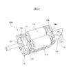
FIG. 2 is a perspective view of a sheet discharge portion according to the first embodiment. -
FIG. 3 is a cross-sectional side view of a first sheet conveyance unit according to the first embodiment. -
FIG. 4 is a perspective view of the first sheet conveyance unit according to the first embodiment. -
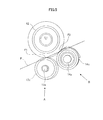
FIG. 5 is a side view illustrating an inclination of a first idler roller and a second idler roller according to the first embodiment. -
FIG. 6 is a perspective view illustrating the inclination of the first idler roller and the second idler roller according to the first embodiment. -
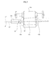
FIG. 7 is a view taken from direction A ofFIGs. 5 and6 . -
FIG. 8 is a view taken from direction B ofFIGs. 5 and6 . -
FIG. 9 is a perspective view of a first idler roller and a second idler roller according to the second embodiment. -
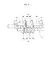
FIG. 10 is a perspective view of a first idler roller and a second idler roller according to a third embodiment. -
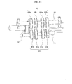
FIG. 11 is a perspective view of a first idler roller and a second idler roller according to a fourth embodiment. -
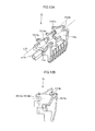
FIG. 12A is a perspective view of a holding member according to the first embodiment. -
FIG. 12B is a front view of the holding member according to the first embodiment. -
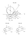
FIG. 13A is an explanatory view of the inclination of a discharge roller, the first idler roller and the second idler roller according to the first embodiment. -
FIG. 13B is a perspective view of the first idler roller. -
FIG. 13C is a perspective view of the second idler roller. -
FIG. 14A is a view illustrating the inclination of a discharge roller, the first idler roller and the second idler roller according to the second embodiment. -
FIG. 14B is a perspective view of the first idler roller. -
FIG. 14C is a perspective view of the second idler roller. - At first, a first embodiment of the present invention will be described. A
printer 100, i.e., image forming apparatus, according to the first embodiment is an electro-photographic laser beam printer. As illustrated inFIG. 1 , theprinter 100 includes asheet feeding cassette 1 capable of being inserted to and drawn from a printermain body 100A, animage forming unit 50 forming an image on a sheet fed from thesheet feeding cassette 1, afixing unit 60, and asheet discharge portion 70. - When an image forming command is output to the
printer 100, an image forming process by theimage forming unit 50 is started based on an image information entered from an external computer and the like connected to theprinter 100. Theimage forming unit 50 includes acartridge 5 having aphotosensitive drum 6, i.e., an image bearing member, alaser scanner 8, and atransfer roller 7. Thelaser scanner 8 irradiates alaser beam 9 toward thephotosensitive drum 6 based on the entered image information. At this time, thephotosensitive drum 6 is charged in advance by a charging roller not shown, and an electrostatic latent image is formed on thephotosensitive drum 6 by irradiating thelaser beam 9. Thereafter, an electrostatic latent image is developed by a developing roller not shown, and a toner image is formed on thephotosensitive drum 6. - In parallel with the above-described image forming process, a sheet S supported on the
sheet feeding cassette 1 is sent out by afeeding roller 2. The sheet S is separated one by one via a separation unit not shown. Then, the sheet S is conveyed via anintermediate transfer roller 3 and a conveyance idler roller 4 toward thetransfer roller 7. Thetransfer roller 7, i.e., transfer unit, transfers a toner image formed on thephotosensitive drum 6 to the sheet S by having a transfer bias applied thereto. - The sheet S having the toner image transferred from the
transfer roller 7 is heated and pressed by thefixing unit 60 composed of aheating roller 10 and apressure roller 11, and the toner image is fixed. Then, the sheet S is discharged onto adischarge tray 30 by thesheet discharge portion 70 arranged downstream of the fixing unit in a sheet conveyance direction. - Next, the
sheet discharge portion 70 will be described in detail. As illustrated inFIG. 2 , thesheet discharge portion 70 includes a dischargeupper guide 16 and a dischargelower guide 18 constituting a discharge conveyance path 31 (refer toFIG. 3 ), and adrive shaft 12a supported rotatably bybearings upper guide 16. Further, thesheet discharge portion 70 includes a firstsheet conveyance unit 80A, i.e., sheet conveyance apparatus, and a secondsheet conveyance unit 80B arranged abreast in a width direction orthogonal to the sheet conveyance direction. The firstsheet conveyance unit 80A and the secondsheet conveyance unit 80B are disposed symmetrically with respect to a center line in the width direction of thedischarge conveyance path 31, and in the present embodiment, only the configuration of the firstsheet conveyance unit 80A is described, and the configuration of the secondsheet conveyance unit 80B will be omitted. - As illustrated in
FIGs. 3 and4 , the firstsheet conveyance unit 80A includes adischarge roller 12, i.e., conveyance roller, fixed to adrive shaft 12a, i.e., rotation shaft, and afirst idler roller 13c, i. e., first rotary member, driven by thedischarge roller 12. Further, the firstsheet conveyance unit 80A includes asecond idler roller 14c, i.e., second rotary member, arranged downstream in the sheet conveyance direction of thefirst idler roller 13c, and driven by thedischarge roller 12. The firstsheet conveyance unit 80A includes, in a rotation shaft direction of thedischarge roller 12, afirst rotation shaft 13, i.e., first shaft portion, extending from both ends of thefirst idler roller 13c, asecond rotation shaft 14, i.e., second shaft portion, extending from both ends of thesecond idler roller 14c, and aholding member 15, i.e., holder, rotatably supporting thefirst rotation shaft 13 and thesecond rotation shaft 14. - A perspective view of the
holding member 15 illustrated inFIG. 12A is referred to in describing a configuration of theholding member 15. Theholding member 15 includes afirst side wall 15a, i.e., first supporting portion, and asecond side wall 15b, i.e., second supporting portion, disposed in parallel with thefirst side wall 15a. Thefirst side wall 15a includes supportingportions end portion 13a of thefirst rotation shaft 13 and oneend portion 14a of thesecond rotation shaft 14 arranged on the same side as the oneend portion 13a. Thesecond side wall 15b includes supportingportions other end portion 13b of thefirst rotation shaft 13 and theother end portion 14b of thesecond rotation shaft 14 arranged on the same side as theother end portion 13b. A virtual line L13 passing the supportingportions portion 1514a and a supportingportion 1514b. -
FIG. 12B illustrates the holdingmember 15 viewed from a direction perpendicular to thefirst side wall 15a. The supportingportions portions first side wall 15a, the supportingportions portions member 15 is designed such that the virtual line L13 is inclined with respect to thedrive shaft 12a of thedischarge roller 12. - The holding
member 15 is attached movably in a substantially vertical direction with respect to the dischargelower guide 18, and aspring 19 is arranged in a compressed manner between the dischargelower guide 18 and the holdingmember 15. Thespring 19 biases thefirst idler roller 13c and thesecond idler roller 14c via the holdingmember 15 to be in pressure contact with thedischarge roller 12. Further, thespring 19 is arranged such that thefirst idler roller 13c and thesecond idler roller 14c press a substantially center position in an axial direction of thedischarge roller 12. - A control unit not shown is provided in the printer
main body 100A, and thedrive shaft 12a is rotated by the control unit driving a drive source not shown. When thedrive shaft 12a rotates, thedischarge roller 12 fixed to thedrive shaft 12a rotates, and along with the rotation of thedischarge roller 12, the first and secondidler rollers - Next, a more detailed arrangement of the first and second
idler rollers FIGs. 5 through 8 .FIG. 5 is a side view of thedischarge roller 12, thefirst idler roller 13c and thesecond idler roller 14c seen from a rotational axis line L1 of thedischarge roller 12.FIG. 7 is a view seen from the direction of arrow A ofFIGs. 5 and6 , andFIG. 8 is a view seen from the direction of arrow B ofFIGs. 5 and6 . The direction of arrow A is a direction perpendicular to a contact surface F1 between thedischarge roller 12 and thefirst idler roller 13c, and the direction of arrow B is a direction perpendicular to a contact surface F2 between thedischarge roller 12 and thesecond idler roller 14c. - As illustrated in
FIG. 7 , thefirst idler roller 13c is arranged such that thefirst rotation shaft 13 is inclined with respect to the rotational axis line L1 of thedischarge roller 12. In other words, a rotational axis line L2 of thefirst idler roller 13c is inclined for angle θ with respect to the rotational axis line L1 of thedischarge roller 12. - Further, as illustrated in
FIG. 8 , thesecond idler roller 14c is arranged such that thesecond rotation shaft 14 is inclined with respect to the rotational axis line L1 of thedischarge roller 12 and thefirst rotation shaft 13. In other words, a rotational axis line L3 of thesecond idler roller 14c is inclined for angle θ with respect to the rotational axis line L1 of thedischarge roller 12. In the present embodiment, the inclination angles of the rotational axis lines L2 and L3 with respect to the rotational axis line L1 are the same angle θ, but the angles can differ as long as the transfer of the sheet S is not hindered. Further, the inclination of thefirst idler roller 13c and thesecond idler roller 14c are set in accordance with the positions of the supportingportions member 15. The angle θ should preferably be 1 degree or greater and 3 degrees or smaller. - Now, as illustrated in
FIGs. 5 and6 , a plane parallel to the rotational axis line L1 of thedischarge roller 12 and including the contact surfaces F1 and F2 is defined as a reference plane P. Thefirst idler roller 13c and thesecond idler roller 14c are arranged to be inclined toward a same direction with respect to a width direction when viewed from a direction orthogonal to the reference plane P. The oneend portion 13a positioned upstream in the sheet conveyance direction of thefirst rotation shaft 13 is arranged closer to the reference plane P than to theother end portion 13b positioned downstream. The oneend portion 14a positioned upstream in the sheet conveyance direction of thesecond rotation shaft 14 is arranged farther from the reference plane P than theother end portion 14b positioned downstream. - As described, according to the present embodiment, the
first idler roller 13c and thesecond idler roller 14c are respectively independently inclined with respect to thedischarge roller 12. Thereby, thefirst idler roller 13c and thesecond idler roller 14c are in contact at a center position in the width direction with thedischarge roller 12. In other words, thefirst idler roller 13c and thesecond idler roller 14c contact thedischarge roller 12 symmetrically with the center position in the width direction set as reference, such that the sheet S can be conveyed stably. Further, damages such as creases of the sheet can be reduced. Furthermore, the present arrangement prevents toner from attaching to the first and secondidler rollers - Next, how the
first idler roller 13c is inclined with respect to thedischarge roller 12 and how thesecond idler roller 14c is inclined with respect to thedischarge roller 12 will be described in detail with reference toFIGs. 13A, 13B and 13C . -
FIG. 13A is a view illustrating thedischarge roller 12, thefirst idler roller 13c and thesecond idler roller 14c from the direction of the rotation axis of thedischarge roller 12. InFIG. 13A , one end face 13cF, i.e., one end, of thefirst idler roller 13c is illustrated by a solid line, and the other end face 13cB, i.e., the other end, is illustrated by a dashed line. A center of one end face 13cF of thefirst idler roller 13c is referred to as C1, and a center of the other end face 13cB is referred to as C1' . A sheet is conveyed by a nip portion N1, i.e., first nip portion, formed by thedischarge roller 12 being in contact with thefirst idler roller 13c . A conveyance direction D1, i.e., first conveyance direction, of a sheet at the nip portion N1 is a direction perpendicular to a line passing a center of the rotation shaft direction of thesecond idler roller 14c, i.e., center of a line segment connecting C1 and C1', and a center of rotation of thedischarge roller 12, when seen from the rotation shaft direction of thedischarge roller 12. - Similarly, in the
second idler roller 14c, one end face 14cF is illustrated by a solid line, and the other end face 14cB is illustrated by a dashed line. A center of one end face 14cF of thesecond idler roller 14c is referred to as C2, and a center of the other end face 14cB is referred to as C2'.FIGs. 13B and 13C are perspective views of thefirst idler roller 13c and thesecond idler roller 14c. A sheet is conveyed by a nip portion N2, i.e., second nip portion, formed by thedischarge roller 12 being in contact with thesecond idler roller 14c. A conveyance direction D2, i.e., second conveyance direction, of a sheet at the nip portion N2 is a direction perpendicular to a line passing a center of the rotation shaft direction of thesecond idler roller 14c, i.e., center of a line segment connecting C2 and C2', and a center of rotation of thedischarge roller 12, when seen from the rotation shaft direction of thedischarge roller 12. - A rotation shaft of the
first idler roller 13c is inclined in the following manner with respect to the rotation shaft of thedischarge roller 12. When seen from the rotation shaft direction of thedischarge roller 12, the center C1' of the other end face 13cB of the rotation shaft direction of thefirst idler roller 13c is shifted downstream with respect to the center C1 of one end face 13cF of the sheet conveyance direction D1 of the nip portion N1. The rotation shaft of thesecond idler roller 14c is inclined in the following manner with respect to the rotation shaft of thedischarge roller 12. When seen from the rotation shaft direction of thedischarge roller 12, the center C2' of the other end face 14cB of the rotation shaft direction of thesecond idler roller 14c is shifted downstream with respect to the center C2 of the one end face 14cF of the sheet conveyance direction D2 of the nip portion N2. - How the
first idler roller 13c and thesecond idler roller 14c are inclined with respect to thedischarge roller 12 will be described with reference toFIGs. 14A, 14B and 14C . -
FIG. 14A is a view illustrating thedischarge roller 12, thefirst idler roller 13c and thesecond idler roller 14c from the rotation shaft direction of thedischarge roller 12. InFIG. 14A , one end face 13cF of thefirst idler roller 13c is illustrated by a solid line, and the other end face 13cB is illustrated by a dashed line. The center of one end face 13cF of thefirst idler roller 13c is referred to as C1, and the center of the other end face 13cB is referred to as C1'. - Similarly, regarding the
second idler roller 14c, one end face 14cF is illustrated by a solid line, and the other end face 14cB is illustrated by a dashed line. The center of one end face 14cF of thesecond idler roller 14c is referred to as C2, and the center of the other end face 14cB is referred to as C2'.FIGs. 14B and 14C are perspective views of thefirst idler roller 13c and thesecond idler roller 14c. The center C1 of the one end face 13cF of thefirst idler roller 13c and the center C2 of the one end face 14cF of thesecond idler roller 14c are arranged on the same side in the rotation shaft direction of thedischarge roller 12. - Now, in a cross section perpendicular to the rotation shaft of the
discharge roller 12, areas divided by a virtual line v12 passing the centers C1 and C2 are referred to as a first area A1 and a second area A2. Thefirst idler roller 13c and thesecond idler roller 14c are respectively inclined with respect to thedischarge roller 12 such that the center C1' of the other end face 13cB of thefirst idler roller 13c is positioned within the first area A1 and the center C2' of the other end face 14cB of thesecond idler roller 14c is positioned within the second area A2. - According further to the present embodiment, as described above, the first and second
sheet conveyance units discharge roller 12 in the rotation axis direction thereof, in the width direction of thedischarge conveyance path 31. The conveyance directions of the first and secondidler rollers sheet conveyance units sheet discharge portion 70, so that skew feeding and forming of creases on the sheet S can be prevented. - In the present embodiment, the
sheet discharge portion 70 has a pair ofsheet conveyance units - Next, a second embodiment of the present invention will be described with reference to
FIG. 9 . The second embodiment has changed the configuration of the first and secondidler rollers - A
first idler roller 23 according to the present embodiment includes a disk-shapedfirst disk portion 23a andsecond disk portion 23b arranged in parallel in the axial direction, and the first andsecond disk portions first rotation shaft 13. Asecond idler roller 24 includes a disk-shapedthird disk portion 24a andfourth disk portion 24b arranged in parallel in the shaft direction, and the third andfourth disk portions second rotation shaft 14. - The first and
second disk portions discharge roller 12. The third andfourth disk portions discharge roller 12. That is,concave portions discharge roller 12, i.e., first and second concave portions, are respectively formed in center portions between the first andsecond disk portions fourth disk portions first rotation shaft 13 and thesecond rotation shaft 14 with respect to the rotational axis line L1 of thedischarge roller 12 is set similarly as the first embodiment. - Therefore, the first and
second disk portions discharge roller 12 symmetrically with respect to the center position in the width direction of theroller 12. Further, the third andfourth disk portions discharge roller 12 symmetrically with respect to the center position in the width direction of theroller 12. Thereby, thedischarge roller 12, thefirst idler roller 23 and thesecond idler roller 24 can convey the sheet S stably and more smoothly, and damages such as creases on the sheet can be reduced. - In the present embodiment, both the first and second
idler rollers idler rollers - Next, a third embodiment of the present invention will be described with reference to
FIG. 10 . The third embodiment has changed the configuration of the first and secondidler rollers - A
first idler roller 33 according to the present embodiment has disk-shaped first disk portion 33a, second disk portion 33b, fifth disk portion 33c and sixth disk portion 33d that are arranged in parallel in the axial direction. The first and second disk portions 33a and 33b are arranged symmetrically with respect to a center position in the width direction of thedischarge roller 12. The fifth and sixth disk portions 33c and 33d are arranged symmetrically with respect to a center position in the width direction of thedischarge roller 12. The inclination of thefirst rotation shaft 13 and thesecond rotation shaft 14 with respect to a rotational axis line L1 of thedischarge roller 12 is set similarly as the first embodiment. - The third and
fourth disk portions second idler roller 24 are arranged in dislocated positions in the axial direction with respect to the first disk portion 33a, the second disk portion 33b, the fifth disk portion 33c and the sixth disk portion 33d. Further, the third andfourth disk portions third disk portion 24a is arranged to be inserted between the first disk portion 33a and the fifth disk portion 33c, and thefourth disk portion 24b is arranged to be inserted between the second disk portion 33b and the sixth disk portion 33d. - According to this arrangement, the outer diameters of the first disk portion 33a, the second disk portion 33b, the
third disk portion 24a, thefourth disk portion 24b, the fifth disk portion 33c and the sixth disk portion 33d can be increased. Thereby, the leading edge of the sheet S can enter the disk portions at a shallow angle, so that the occurrence of sheet jam or damages to the leading edge of the sheet can be reduced. - The present embodiment adopts a configuration where the
first idler roller 33 includes four disk portions and thesecond idler roller 24 includes two disk portions, but the number of disk portions can be set to any arbitrary number. - Next, a fourth embodiment of the present invention will be described with reference to
FIG. 11 . The fourth embodiment has changed the configuration of the first and secondidler rollers - A
first idler roller 43 according to the present embodiment includes two center disk portions 43a and 43a disposed at a center portion in a width direction, and two end disk portions 43b and 43b disposed at both end portions in the width direction. The end disk portions 43b and 43b are set to have smaller outer diameters than the center disk portions 43a and 43a, and thefirst idler roller 43 is designed to be barrel-shaped as a whole. - Moreover, the
second idler roller 44 has twocenter disk portions end disk portions end disk portions center disk portions second idler roller 44 is barrel-shaped. The inclination of thefirst rotation shaft 13 and thesecond rotation shaft 14 with respect to the rotational axis line of thedischarge roller 12 is set similarly as the first embodiment. - According to the present embodiment, the
first idler roller 43 is barrel-shaped as a whole, so that the sheet S expanded between the fixingunit 60 and thesheet discharge portion 70 can be prevented from being in contact locally with the end portion of thefirst idler roller 43. That is, since thefirst idler roller 43 is arranged in an inclined manner with respect to thedischarge roller 12, thefirst idler roller 43 contacts the sheet with stronger force at the upstream side in the sheet conveyance direction than the downstream side of theroller 43. However, since theend disk portions center disk portions - While the present invention has been described with reference to exemplary embodiments, it is to be understood that the invention is not limited to the disclosed exemplary embodiments. The scope of the following claims is to be accorded the broadest interpretation so as to encompass all such modifications and equivalent structures and functions.
A sheet conveyance apparatus includes a conveyance roller (12), a first rotary member (13c) configured to be rotated in contact with the conveyance roller (12), a second rotary member (14c) configured to be rotated in contact with the conveyance roller (12). In a case where two areas divided by a virtual line (v12) passing a center (C1) of one end (13cF) of the first rotary member (13c) and a center (C2) of one end (14cF) of the second rotary member (14c) are referred to as a first area (A1) and a second area (A2), a center (C1') of the other end (13cB) of the first rotary member (13c) is positioned within the first area (A1) , and a center (C2') of the other end (14cB) of the second rotary member (14c) is positioned within the second area (A2).
Claims (8)
- A sheet conveyance apparatus comprising:a conveyance roller (12);a first rotary member (13c) configured to be rotated in contact with the conveyance roller (12), and forming a first nip portion (N1), conveying a sheet in a first conveyance direction (D1), together with the conveyance roller (12); anda second rotary member (14c) configured to be rotated in contact with the conveyance roller (12), and forming a second nip portion (N2), conveying the sheet in a second conveyance direction (D2), together with the conveyance roller (12), the second rotary member (14c) being provided downstream of the first rotary member (13c) in a rotation direction of the conveyance roller,wherein a rotation axis (L2) of the first rotary member (13c) and a rotation axis (L3) of the second rotary member (14c) are inclined with respect to a rotation axis (L1) of the conveyance roller (12), and
in a cross section perpendicular to the rotation axis (L1) of the conveyance roller (12), in a case where two areas divided by a virtual line (v12) passing a center (C1) of one end (13cF) of the first rotary member (13c) and a center (C2) of one end (14cF) of the second rotary member (14c) arranged on a same side as the one end (13cF) of the first rotary member (13c) are referred to as a first area (A1) and a second area (A2), a center (C1') of the other end (13cB) of the first rotary member (13c) is positioned within the first area (A1), and a center (C2') of the other end (14cB) of the second rotary member (14c) is positioned within the second area (A2). - A sheet conveyance apparatus comprising:a conveyance roller (12);a first rotary member (13c) configured to be rotated in contact with the conveyance roller (12), and forming a first nip portion (N1), conveying a sheet in a first conveyance direction (D1), together with the conveyance roller (12), a rotation axis (L2) of the first rotary member (13c) being inclined with respect to a rotation axis (L1) of the conveyance roller (12) such that a center (C1) of one end (13cF) of the first rotary member (13c) is positioned at a different position in the first conveyance direction (D1) with respect to a center (C1') of the other end (13cB) of the first rotary member (13c) in a view from a rotation axis direction of the conveyance roller (12); anda second rotary member (14c) configured to be rotated in contact with the conveyance roller (12), and forming a second nip portion (N2), conveying the sheet in a second conveyance direction (D2), together with the conveyance roller (12), the second rotary member (14c) being provided downstream of the first rotary member (13c) in a rotation direction of the conveyance roller (12), a rotation axis (L3) of the second rotary member (14c) being inclined with respect to the rotation axis (L1) of the conveyance roller (12) such that a center (C2) of one end (14cF) of the second rotary member (14c) is positioned at a different position in the second conveyance direction (D2) with respect to a center (C2 ') of the other end (14cB) in a view from the rotation axis direction of the conveyance roller (12).
- A sheet conveyance apparatus comprising:a conveyance roller (12);a first rotary member (13c) configured to be rotated in contact with the conveyance roller (12), and forming a first nip portion (N1), conveying a sheet in a first conveyance direction (D1), together with the conveyance roller (12); anda second rotary member (14c) configured to be rotated in contact with the conveyance roller (12), and forming a second nip portion (N2), conveying the sheet in a second conveyance direction (D2), together with the conveyance roller (12), the second rotary member (14c) provided downstream of the first rotary member (13c) in a rotation direction of the conveyance roller (12),wherein a rotation axis (L2) of the first rotary member (13c) and a rotation axis (L3) of the second rotary member (14c) are inclined with respect to a rotation axis (L1) of the conveyance roller (12), and
the rotation axis (L2) of the first rotary member (13c) and the rotation axis (L3) of the second rotary member (14c) are not parallel. - The sheet conveyance apparatus according to any one of claims 1 to 3, further comprising a holder (15) holding the first rotary member (13c) and the second rotary member (14c) in a rotatable manner such that the rotation axis (L2) of the first rotary member (13c) and the rotation axis (L3) of the second rotary member (14c) are not parallel.
- The sheet conveyance apparatus according to claim 4, wherein the first rotary member (13c) comprises a first shaft portion (13) extending from both ends in a rotation axis direction thereof,
the second rotary member (14c) comprises a second shaft portion (14) extending from both ends in a rotation axis direction thereof, and
the holder (15) comprises a first supporting portion (15a) supporting one end (13a) of the first shaft portion (13) and one end (14a) of the second shaft portion (14) arranged on a same side as the one end (13a) of the first shaft portion (13), and a second supporting portion (15b) supporting the other end (13b) of the first shaft portion (13) and the other end (14b) of the second shaft portion (14) arranged on a same side as the other end (13b) of the first shaft portion (13). - The sheet conveyance apparatus according to any one of claims 1 to 5, wherein an angle (θ) formed between the rotation axis (L1) of the conveyance roller (12) and the rotation axis (L2) of the first rotary member (13c) is one degree or greater and three degrees or smaller, and an angle (θ) formed between the rotation axis (L1) of the conveyance roller (12) and the rotation axis (L3) of the second rotary member (14c) is one degree or greater and three degrees or smaller.
- The sheet conveyance apparatus according to any one of claims 1 to 6, wherein the first rotary member (13c) and the second rotary member (14c) are inclined around a center portion of the conveyance roller in the rotation axis direction thereof.
- The sheet conveyance apparatus according to any one of claims 1 to 7, wherein a center portion of the first rotary member (13c) in a rotation axis direction thereof comprises a first concave portion (23c) not in contact with the conveyance roller (12), and
a center portion of the second rotary member (14c) in a rotation axis direction thereof comprises a second concave portion (24c) not in contact with the conveyance roller (12).
Applications Claiming Priority (2)
| Application Number | Priority Date | Filing Date | Title |
|---|---|---|---|
| JP2015136302 | 2015-07-07 | ||
| JP2016112008A JP6768355B2 (en) | 2015-07-07 | 2016-06-03 | Sheet transfer device and image forming device |
Publications (2)
| Publication Number | Publication Date |
|---|---|
| EP3115323A1 true EP3115323A1 (en) | 2017-01-11 |
| EP3115323B1 EP3115323B1 (en) | 2022-05-25 |
Family
ID=56148207
Family Applications (1)
| Application Number | Title | Priority Date | Filing Date |
|---|---|---|---|
| EP16175181.3A Active EP3115323B1 (en) | 2015-07-07 | 2016-06-20 | Sheet conveyance apparatus |
Country Status (3)
| Country | Link |
|---|---|
| US (3) | US10023411B2 (en) |
| EP (1) | EP3115323B1 (en) |
| CN (1) | CN106335812B (en) |
Families Citing this family (8)
| Publication number | Priority date | Publication date | Assignee | Title |
|---|---|---|---|---|
| JP6682226B2 (en) * | 2015-10-02 | 2020-04-15 | キヤノン株式会社 | Image forming device |
| JP6551133B2 (en) * | 2015-10-13 | 2019-07-31 | 村田機械株式会社 | Paper discharge device |
| JP6950220B2 (en) * | 2017-03-24 | 2021-10-13 | 富士フイルムビジネスイノベーション株式会社 | Recording medium processing device and image forming device |
| US10865066B2 (en) * | 2018-03-14 | 2020-12-15 | Brother Kogyo Kabushiki Kaisha | Sheet discharging device including pinch roller movable relative to drive roller, and guide member for guiding sheets |
| CN108405474B (en) * | 2018-05-25 | 2024-07-30 | 张家港市科宇信超声有限公司 | Discharging mechanism for ultrasonic cleaning device |
| JP2021006482A (en) * | 2019-06-27 | 2021-01-21 | キヤノン株式会社 | Sheet transfer device and image forming device |
| JP2024024174A (en) * | 2022-08-09 | 2024-02-22 | キヤノン株式会社 | Sheet conveyance device |
| US20240375900A1 (en) * | 2023-05-09 | 2024-11-14 | Naoki Hoshi | Conveyor and image forming apparatus |
Citations (5)
| Publication number | Priority date | Publication date | Assignee | Title |
|---|---|---|---|---|
| JP2007145452A (en) | 2005-11-24 | 2007-06-14 | Canon Inc | Sheet conveying apparatus and image forming apparatus |
| JP2009057174A (en) * | 2007-08-31 | 2009-03-19 | Ricoh Co Ltd | Sheet conveying apparatus and image forming apparatus |
| JP2010195544A (en) | 2009-02-26 | 2010-09-09 | Brother Ind Ltd | Image forming device |
| US20110115148A1 (en) * | 2009-11-19 | 2011-05-19 | Oki Data Corporation | Medium carrying mechanism and image forming device |
| US20150098741A1 (en) * | 2013-10-09 | 2015-04-09 | Canon Kabushiki Kaisha | Image forming apparatus |
Family Cites Families (15)
| Publication number | Priority date | Publication date | Assignee | Title |
|---|---|---|---|---|
| JPH06321379A (en) | 1993-05-10 | 1994-11-22 | Canon Inc | Automatic feeding device and recording device having the same |
| US5793399A (en) | 1993-12-27 | 1998-08-11 | Canon Kabushiki Kaisha | Sheet supplying apparatus |
| EP0694491B1 (en) | 1994-07-29 | 2003-01-22 | Canon Kabushiki Kaisha | Sheet supply apparatus |
| JP3311157B2 (en) | 1994-07-29 | 2002-08-05 | キヤノン株式会社 | Sheet material feeding device and recording device |
| EP0694490B1 (en) | 1994-07-29 | 2000-05-31 | Canon Kabushiki Kaisha | Sheet supply apparatus |
| US5867196A (en) | 1994-07-29 | 1999-02-02 | Canon Kabushiki Kaisha | Sheet supply apparatus for controlling sheet feeding with reversing of conveyance direction |
| JP3472137B2 (en) | 1998-04-28 | 2003-12-02 | キヤノン株式会社 | Fixing device and image forming device |
| KR100467624B1 (en) * | 2003-01-13 | 2005-01-24 | 삼성전자주식회사 | Paper aligning apparatus for duplex printer |
| JP4243864B2 (en) * | 2005-01-26 | 2009-03-25 | ブラザー工業株式会社 | Conveying device and ink jet recording apparatus provided with the same |
| JP2006232523A (en) | 2005-02-28 | 2006-09-07 | Canon Inc | Recording sheet transport device |
| JP4455371B2 (en) | 2005-02-28 | 2010-04-21 | キヤノン株式会社 | Sheet reversing and conveying apparatus, image reading apparatus, and image reading and forming apparatus |
| KR101206442B1 (en) * | 2007-06-12 | 2012-11-29 | 삼성전자주식회사 | Discharging unit and image forming apparatus having the same |
| JP2009132522A (en) | 2007-11-30 | 2009-06-18 | Ricoh Co Ltd | Sheet material conveying apparatus and image forming apparatus |
| JP2012126481A (en) | 2010-12-14 | 2012-07-05 | Canon Inc | Sheet ejection device and image forming apparatus |
| JP6682226B2 (en) * | 2015-10-02 | 2020-04-15 | キヤノン株式会社 | Image forming device |
-
2016
- 2016-06-20 EP EP16175181.3A patent/EP3115323B1/en active Active
- 2016-06-29 US US15/196,216 patent/US10023411B2/en active Active
- 2016-07-06 CN CN201610526000.4A patent/CN106335812B/en active Active
-
2018
- 2018-06-13 US US16/007,019 patent/US10669110B2/en active Active
-
2020
- 2020-04-23 US US16/856,341 patent/US11447350B2/en active Active
Patent Citations (5)
| Publication number | Priority date | Publication date | Assignee | Title |
|---|---|---|---|---|
| JP2007145452A (en) | 2005-11-24 | 2007-06-14 | Canon Inc | Sheet conveying apparatus and image forming apparatus |
| JP2009057174A (en) * | 2007-08-31 | 2009-03-19 | Ricoh Co Ltd | Sheet conveying apparatus and image forming apparatus |
| JP2010195544A (en) | 2009-02-26 | 2010-09-09 | Brother Ind Ltd | Image forming device |
| US20110115148A1 (en) * | 2009-11-19 | 2011-05-19 | Oki Data Corporation | Medium carrying mechanism and image forming device |
| US20150098741A1 (en) * | 2013-10-09 | 2015-04-09 | Canon Kabushiki Kaisha | Image forming apparatus |
Also Published As
| Publication number | Publication date |
|---|---|
| US11447350B2 (en) | 2022-09-20 |
| CN106335812A (en) | 2017-01-18 |
| US20180290847A1 (en) | 2018-10-11 |
| US10669110B2 (en) | 2020-06-02 |
| EP3115323B1 (en) | 2022-05-25 |
| US20170008713A1 (en) | 2017-01-12 |
| US10023411B2 (en) | 2018-07-17 |
| US20200247630A1 (en) | 2020-08-06 |
| CN106335812B (en) | 2018-12-28 |
Similar Documents
| Publication | Publication Date | Title |
|---|---|---|
| US11447350B2 (en) | Sheet conveyance apparatus | |
| US7571908B2 (en) | Sheet conveying apparatus and image forming apparatus | |
| US7810809B2 (en) | Sheet conveying apparatus and image forming apparatus | |
| US9908727B2 (en) | Sheet conveyance apparatus and image forming apparatus | |
| JP2009196803A (en) | Paper conveying device | |
| JP3962701B2 (en) | Sheet conveying apparatus and image forming apparatus | |
| US6473592B2 (en) | Sheet conveying apparatus with curl correction and image forming apparatus having same | |
| US11724900B2 (en) | Sheet conveying device and sheet conveying method | |
| US10882708B2 (en) | Sheet conveyance device, image forming apparatus, method, and storage medium | |
| JP6376759B2 (en) | Sheet discharging apparatus and image forming apparatus | |
| US20160209797A1 (en) | Image Forming Apparatus Configured to Execute Duplex Printing | |
| US10053320B2 (en) | Sheet conveyance apparatus and image forming apparatus | |
| US9989910B2 (en) | Image forming apparatus | |
| US10509345B1 (en) | Image forming apparatus for correcting curl of paper | |
| US11613440B2 (en) | Sheet conveyance device and image forming apparatus | |
| JP6768355B2 (en) | Sheet transfer device and image forming device | |
| EP3251991A1 (en) | Image forming apparatus | |
| JP2005263343A (en) | Sheet conveying apparatus and image forming apparatus | |
| US10221884B2 (en) | Rotating shaft, roller, sheet conveyance device, and image forming apparatus | |
| JP2015093777A (en) | Image formation device | |
| JP2004161390A (en) | Sheet conveying apparatus and image forming apparatus having the same | |
| JP2014174285A (en) | Conveyance path of sheet material, and image forming apparatus | |
| JP2015093779A (en) | Image forming apparatus | |
| JP2006248737A (en) | Sheet conveying apparatus and image forming apparatus |
Legal Events
| Date | Code | Title | Description |
|---|---|---|---|
| PUAI | Public reference made under article 153(3) epc to a published international application that has entered the european phase |
Free format text: ORIGINAL CODE: 0009012 |
|
| STAA | Information on the status of an ep patent application or granted ep patent |
Free format text: STATUS: THE APPLICATION HAS BEEN PUBLISHED |
|
| AK | Designated contracting states |
Kind code of ref document: A1 Designated state(s): AL AT BE BG CH CY CZ DE DK EE ES FI FR GB GR HR HU IE IS IT LI LT LU LV MC MK MT NL NO PL PT RO RS SE SI SK SM TR |
|
| AX | Request for extension of the european patent |
Extension state: BA ME |
|
| STAA | Information on the status of an ep patent application or granted ep patent |
Free format text: STATUS: REQUEST FOR EXAMINATION WAS MADE |
|
| 17P | Request for examination filed |
Effective date: 20170711 |
|
| RBV | Designated contracting states (corrected) |
Designated state(s): AL AT BE BG CH CY CZ DE DK EE ES FI FR GB GR HR HU IE IS IT LI LT LU LV MC MK MT NL NO PL PT RO RS SE SI SK SM TR |
|
| STAA | Information on the status of an ep patent application or granted ep patent |
Free format text: STATUS: EXAMINATION IS IN PROGRESS |
|
| 17Q | First examination report despatched |
Effective date: 20201028 |
|
| GRAP | Despatch of communication of intention to grant a patent |
Free format text: ORIGINAL CODE: EPIDOSNIGR1 |
|
| STAA | Information on the status of an ep patent application or granted ep patent |
Free format text: STATUS: GRANT OF PATENT IS INTENDED |
|
| INTG | Intention to grant announced |
Effective date: 20211215 |
|
| GRAS | Grant fee paid |
Free format text: ORIGINAL CODE: EPIDOSNIGR3 |
|
| GRAA | (expected) grant |
Free format text: ORIGINAL CODE: 0009210 |
|
| STAA | Information on the status of an ep patent application or granted ep patent |
Free format text: STATUS: THE PATENT HAS BEEN GRANTED |
|
| AK | Designated contracting states |
Kind code of ref document: B1 Designated state(s): AL AT BE BG CH CY CZ DE DK EE ES FI FR GB GR HR HU IE IS IT LI LT LU LV MC MK MT NL NO PL PT RO RS SE SI SK SM TR |
|
| REG | Reference to a national code |
Ref country code: GB Ref legal event code: FG4D |
|
| REG | Reference to a national code |
Ref country code: CH Ref legal event code: EP |
|
| REG | Reference to a national code |
Ref country code: DE Ref legal event code: R096 Ref document number: 602016072357 Country of ref document: DE |
|
| REG | Reference to a national code |
Ref country code: AT Ref legal event code: REF Ref document number: 1494187 Country of ref document: AT Kind code of ref document: T Effective date: 20220615 |
|
| REG | Reference to a national code |
Ref country code: IE Ref legal event code: FG4D |
|
| REG | Reference to a national code |
Ref country code: LT Ref legal event code: MG9D |
|
| REG | Reference to a national code |
Ref country code: NL Ref legal event code: MP Effective date: 20220525 |
|
| REG | Reference to a national code |
Ref country code: AT Ref legal event code: MK05 Ref document number: 1494187 Country of ref document: AT Kind code of ref document: T Effective date: 20220525 |
|
| PG25 | Lapsed in a contracting state [announced via postgrant information from national office to epo] |
Ref country code: SE Free format text: LAPSE BECAUSE OF FAILURE TO SUBMIT A TRANSLATION OF THE DESCRIPTION OR TO PAY THE FEE WITHIN THE PRESCRIBED TIME-LIMIT Effective date: 20220525 Ref country code: PT Free format text: LAPSE BECAUSE OF FAILURE TO SUBMIT A TRANSLATION OF THE DESCRIPTION OR TO PAY THE FEE WITHIN THE PRESCRIBED TIME-LIMIT Effective date: 20220926 Ref country code: NO Free format text: LAPSE BECAUSE OF FAILURE TO SUBMIT A TRANSLATION OF THE DESCRIPTION OR TO PAY THE FEE WITHIN THE PRESCRIBED TIME-LIMIT Effective date: 20220825 Ref country code: NL Free format text: LAPSE BECAUSE OF FAILURE TO SUBMIT A TRANSLATION OF THE DESCRIPTION OR TO PAY THE FEE WITHIN THE PRESCRIBED TIME-LIMIT Effective date: 20220525 Ref country code: LT Free format text: LAPSE BECAUSE OF FAILURE TO SUBMIT A TRANSLATION OF THE DESCRIPTION OR TO PAY THE FEE WITHIN THE PRESCRIBED TIME-LIMIT Effective date: 20220525 Ref country code: HR Free format text: LAPSE BECAUSE OF FAILURE TO SUBMIT A TRANSLATION OF THE DESCRIPTION OR TO PAY THE FEE WITHIN THE PRESCRIBED TIME-LIMIT Effective date: 20220525 Ref country code: GR Free format text: LAPSE BECAUSE OF FAILURE TO SUBMIT A TRANSLATION OF THE DESCRIPTION OR TO PAY THE FEE WITHIN THE PRESCRIBED TIME-LIMIT Effective date: 20220826 Ref country code: FI Free format text: LAPSE BECAUSE OF FAILURE TO SUBMIT A TRANSLATION OF THE DESCRIPTION OR TO PAY THE FEE WITHIN THE PRESCRIBED TIME-LIMIT Effective date: 20220525 Ref country code: ES Free format text: LAPSE BECAUSE OF FAILURE TO SUBMIT A TRANSLATION OF THE DESCRIPTION OR TO PAY THE FEE WITHIN THE PRESCRIBED TIME-LIMIT Effective date: 20220525 Ref country code: BG Free format text: LAPSE BECAUSE OF FAILURE TO SUBMIT A TRANSLATION OF THE DESCRIPTION OR TO PAY THE FEE WITHIN THE PRESCRIBED TIME-LIMIT Effective date: 20220825 Ref country code: AT Free format text: LAPSE BECAUSE OF FAILURE TO SUBMIT A TRANSLATION OF THE DESCRIPTION OR TO PAY THE FEE WITHIN THE PRESCRIBED TIME-LIMIT Effective date: 20220525 |
|
| PG25 | Lapsed in a contracting state [announced via postgrant information from national office to epo] |
Ref country code: RS Free format text: LAPSE BECAUSE OF FAILURE TO SUBMIT A TRANSLATION OF THE DESCRIPTION OR TO PAY THE FEE WITHIN THE PRESCRIBED TIME-LIMIT Effective date: 20220525 Ref country code: PL Free format text: LAPSE BECAUSE OF FAILURE TO SUBMIT A TRANSLATION OF THE DESCRIPTION OR TO PAY THE FEE WITHIN THE PRESCRIBED TIME-LIMIT Effective date: 20220525 Ref country code: LV Free format text: LAPSE BECAUSE OF FAILURE TO SUBMIT A TRANSLATION OF THE DESCRIPTION OR TO PAY THE FEE WITHIN THE PRESCRIBED TIME-LIMIT Effective date: 20220525 Ref country code: IS Free format text: LAPSE BECAUSE OF FAILURE TO SUBMIT A TRANSLATION OF THE DESCRIPTION OR TO PAY THE FEE WITHIN THE PRESCRIBED TIME-LIMIT Effective date: 20220925 |
|
| PG25 | Lapsed in a contracting state [announced via postgrant information from national office to epo] |
Ref country code: SM Free format text: LAPSE BECAUSE OF FAILURE TO SUBMIT A TRANSLATION OF THE DESCRIPTION OR TO PAY THE FEE WITHIN THE PRESCRIBED TIME-LIMIT Effective date: 20220525 Ref country code: SK Free format text: LAPSE BECAUSE OF FAILURE TO SUBMIT A TRANSLATION OF THE DESCRIPTION OR TO PAY THE FEE WITHIN THE PRESCRIBED TIME-LIMIT Effective date: 20220525 Ref country code: RO Free format text: LAPSE BECAUSE OF FAILURE TO SUBMIT A TRANSLATION OF THE DESCRIPTION OR TO PAY THE FEE WITHIN THE PRESCRIBED TIME-LIMIT Effective date: 20220525 Ref country code: EE Free format text: LAPSE BECAUSE OF FAILURE TO SUBMIT A TRANSLATION OF THE DESCRIPTION OR TO PAY THE FEE WITHIN THE PRESCRIBED TIME-LIMIT Effective date: 20220525 Ref country code: DK Free format text: LAPSE BECAUSE OF FAILURE TO SUBMIT A TRANSLATION OF THE DESCRIPTION OR TO PAY THE FEE WITHIN THE PRESCRIBED TIME-LIMIT Effective date: 20220525 Ref country code: CZ Free format text: LAPSE BECAUSE OF FAILURE TO SUBMIT A TRANSLATION OF THE DESCRIPTION OR TO PAY THE FEE WITHIN THE PRESCRIBED TIME-LIMIT Effective date: 20220525 |
|
| REG | Reference to a national code |
Ref country code: CH Ref legal event code: PL |
|
| REG | Reference to a national code |
Ref country code: BE Ref legal event code: MM Effective date: 20220630 |
|
| PG25 | Lapsed in a contracting state [announced via postgrant information from national office to epo] |
Ref country code: MC Free format text: LAPSE BECAUSE OF FAILURE TO SUBMIT A TRANSLATION OF THE DESCRIPTION OR TO PAY THE FEE WITHIN THE PRESCRIBED TIME-LIMIT Effective date: 20220525 |
|
| REG | Reference to a national code |
Ref country code: DE Ref legal event code: R097 Ref document number: 602016072357 Country of ref document: DE |
|
| PG25 | Lapsed in a contracting state [announced via postgrant information from national office to epo] |
Ref country code: AL Free format text: LAPSE BECAUSE OF FAILURE TO SUBMIT A TRANSLATION OF THE DESCRIPTION OR TO PAY THE FEE WITHIN THE PRESCRIBED TIME-LIMIT Effective date: 20220525 |
|
| PLBE | No opposition filed within time limit |
Free format text: ORIGINAL CODE: 0009261 |
|
| STAA | Information on the status of an ep patent application or granted ep patent |
Free format text: STATUS: NO OPPOSITION FILED WITHIN TIME LIMIT |
|
| PG25 | Lapsed in a contracting state [announced via postgrant information from national office to epo] |
Ref country code: LU Free format text: LAPSE BECAUSE OF NON-PAYMENT OF DUE FEES Effective date: 20220620 Ref country code: LI Free format text: LAPSE BECAUSE OF NON-PAYMENT OF DUE FEES Effective date: 20220630 Ref country code: IE Free format text: LAPSE BECAUSE OF NON-PAYMENT OF DUE FEES Effective date: 20220620 Ref country code: FR Free format text: LAPSE BECAUSE OF NON-PAYMENT OF DUE FEES Effective date: 20220725 Ref country code: CH Free format text: LAPSE BECAUSE OF NON-PAYMENT OF DUE FEES Effective date: 20220630 |
|
| 26N | No opposition filed |
Effective date: 20230228 |
|
| PG25 | Lapsed in a contracting state [announced via postgrant information from national office to epo] |
Ref country code: SI Free format text: LAPSE BECAUSE OF FAILURE TO SUBMIT A TRANSLATION OF THE DESCRIPTION OR TO PAY THE FEE WITHIN THE PRESCRIBED TIME-LIMIT Effective date: 20220525 Ref country code: BE Free format text: LAPSE BECAUSE OF NON-PAYMENT OF DUE FEES Effective date: 20220630 |
|
| PG25 | Lapsed in a contracting state [announced via postgrant information from national office to epo] |
Ref country code: IT Free format text: LAPSE BECAUSE OF FAILURE TO SUBMIT A TRANSLATION OF THE DESCRIPTION OR TO PAY THE FEE WITHIN THE PRESCRIBED TIME-LIMIT Effective date: 20220525 |
|
| PG25 | Lapsed in a contracting state [announced via postgrant information from national office to epo] |
Ref country code: HU Free format text: LAPSE BECAUSE OF FAILURE TO SUBMIT A TRANSLATION OF THE DESCRIPTION OR TO PAY THE FEE WITHIN THE PRESCRIBED TIME-LIMIT; INVALID AB INITIO Effective date: 20160620 |
|
| PG25 | Lapsed in a contracting state [announced via postgrant information from national office to epo] |
Ref country code: MK Free format text: LAPSE BECAUSE OF FAILURE TO SUBMIT A TRANSLATION OF THE DESCRIPTION OR TO PAY THE FEE WITHIN THE PRESCRIBED TIME-LIMIT Effective date: 20220525 Ref country code: CY Free format text: LAPSE BECAUSE OF FAILURE TO SUBMIT A TRANSLATION OF THE DESCRIPTION OR TO PAY THE FEE WITHIN THE PRESCRIBED TIME-LIMIT Effective date: 20220525 |
|
| PG25 | Lapsed in a contracting state [announced via postgrant information from national office to epo] |
Ref country code: TR Free format text: LAPSE BECAUSE OF FAILURE TO SUBMIT A TRANSLATION OF THE DESCRIPTION OR TO PAY THE FEE WITHIN THE PRESCRIBED TIME-LIMIT Effective date: 20220525 |
|
| PG25 | Lapsed in a contracting state [announced via postgrant information from national office to epo] |
Ref country code: MT Free format text: LAPSE BECAUSE OF FAILURE TO SUBMIT A TRANSLATION OF THE DESCRIPTION OR TO PAY THE FEE WITHIN THE PRESCRIBED TIME-LIMIT Effective date: 20220525 |
|
| PG25 | Lapsed in a contracting state [announced via postgrant information from national office to epo] |
Ref country code: BG Free format text: LAPSE BECAUSE OF FAILURE TO SUBMIT A TRANSLATION OF THE DESCRIPTION OR TO PAY THE FEE WITHIN THE PRESCRIBED TIME-LIMIT Effective date: 20220525 |
|
| PG25 | Lapsed in a contracting state [announced via postgrant information from national office to epo] |
Ref country code: BG Free format text: LAPSE BECAUSE OF FAILURE TO SUBMIT A TRANSLATION OF THE DESCRIPTION OR TO PAY THE FEE WITHIN THE PRESCRIBED TIME-LIMIT Effective date: 20220525 |
|
| PGFP | Annual fee paid to national office [announced via postgrant information from national office to epo] |
Ref country code: DE Payment date: 20250520 Year of fee payment: 10 |
|
| PGFP | Annual fee paid to national office [announced via postgrant information from national office to epo] |
Ref country code: GB Payment date: 20250520 Year of fee payment: 10 |