EP3115282A1 - Locking mechanism for a side skirt - Google Patents
Locking mechanism for a side skirt Download PDFInfo
- Publication number
- EP3115282A1 EP3115282A1 EP15175404.1A EP15175404A EP3115282A1 EP 3115282 A1 EP3115282 A1 EP 3115282A1 EP 15175404 A EP15175404 A EP 15175404A EP 3115282 A1 EP3115282 A1 EP 3115282A1
- Authority
- EP
- European Patent Office
- Prior art keywords
- hook member
- main
- counterpart
- locking mechanism
- side skirt
- Prior art date
- Legal status (The legal status is an assumption and is not a legal conclusion. Google has not performed a legal analysis and makes no representation as to the accuracy of the status listed.)
- Granted
Links
Images




Classifications
-
- B—PERFORMING OPERATIONS; TRANSPORTING
- B62—LAND VEHICLES FOR TRAVELLING OTHERWISE THAN ON RAILS
- B62D—MOTOR VEHICLES; TRAILERS
- B62D35/00—Vehicle bodies characterised by streamlining
- B62D35/001—For commercial vehicles or tractor-trailer combinations, e.g. caravans
-
- E—FIXED CONSTRUCTIONS
- E05—LOCKS; KEYS; WINDOW OR DOOR FITTINGS; SAFES
- E05B—LOCKS; ACCESSORIES THEREFOR; HANDCUFFS
- E05B15/00—Other details of locks; Parts for engagement by bolts of fastening devices
- E05B15/004—Lost motion connections
-
- E—FIXED CONSTRUCTIONS
- E05—LOCKS; KEYS; WINDOW OR DOOR FITTINGS; SAFES
- E05B—LOCKS; ACCESSORIES THEREFOR; HANDCUFFS
- E05B63/00—Locks or fastenings with special structural characteristics
- E05B63/14—Arrangement of several locks or locks with several bolts, e.g. arranged one behind the other
-
- E—FIXED CONSTRUCTIONS
- E05—LOCKS; KEYS; WINDOW OR DOOR FITTINGS; SAFES
- E05B—LOCKS; ACCESSORIES THEREFOR; HANDCUFFS
- E05B77/00—Vehicle locks characterised by special functions or purposes
- E05B77/36—Noise prevention; Anti-rattling means
- E05B77/38—Cushion elements, elastic guiding elements or holding elements, e.g. for cushioning or damping the impact of the bolt against the striker during closing of the wing
-
- E—FIXED CONSTRUCTIONS
- E05—LOCKS; KEYS; WINDOW OR DOOR FITTINGS; SAFES
- E05B—LOCKS; ACCESSORIES THEREFOR; HANDCUFFS
- E05B83/00—Vehicle locks specially adapted for particular types of wing or vehicle
- E05B83/16—Locks for luggage compartments, car boot lids or car bonnets
- E05B83/22—Locks for luggage compartments, car boot lids or car bonnets for luggage compartments at the side of the vehicle, e.g. of buses or camper vans
-
- E—FIXED CONSTRUCTIONS
- E05—LOCKS; KEYS; WINDOW OR DOOR FITTINGS; SAFES
- E05C—BOLTS OR FASTENING DEVICES FOR WINGS, SPECIALLY FOR DOORS OR WINDOWS
- E05C3/00—Fastening devices with bolts moving pivotally or rotatively
- E05C3/12—Fastening devices with bolts moving pivotally or rotatively with latching action
- E05C3/14—Fastening devices with bolts moving pivotally or rotatively with latching action with operating handle or equivalent member rigid with the latch
-
- E—FIXED CONSTRUCTIONS
- E05—LOCKS; KEYS; WINDOW OR DOOR FITTINGS; SAFES
- E05C—BOLTS OR FASTENING DEVICES FOR WINGS, SPECIALLY FOR DOORS OR WINDOWS
- E05C3/00—Fastening devices with bolts moving pivotally or rotatively
- E05C3/12—Fastening devices with bolts moving pivotally or rotatively with latching action
- E05C3/16—Fastening devices with bolts moving pivotally or rotatively with latching action with operating handle or equivalent member moving otherwise than rigidly with the latch
- E05C3/22—Fastening devices with bolts moving pivotally or rotatively with latching action with operating handle or equivalent member moving otherwise than rigidly with the latch the bolt being spring controlled
- E05C3/30—Fastening devices with bolts moving pivotally or rotatively with latching action with operating handle or equivalent member moving otherwise than rigidly with the latch the bolt being spring controlled in the form of a hook
- E05C3/34—Fastening devices with bolts moving pivotally or rotatively with latching action with operating handle or equivalent member moving otherwise than rigidly with the latch the bolt being spring controlled in the form of a hook with simultaneously operating double bolts
Definitions
- the invention relates to a locking mechanism for a side skirt of a vehicle. Further, the invention relates to a side skirt with such a locking mechanism and a vehicle with such a side skirt.
- a locking mechanism of a side skirt of a vehicle uses a simple extension cord lock mechanism which is mounted on the side skirt mount bracket. To unlock a user had to pull the extension cord to himself and for locking the side skirt panel he had to be pushed forward and down.
- US 2014 / 0028055 A1 discloses a side skirt mounting apparatus.
- the apparatus according to US 2014 / 0028055 A1 includes a side skirt that may be installed to be supported by a one-touch locker in an upper portion thereof and a hinge in a lower portion thereof.
- the locker includes an upper bracket, a lower bracket, a skirt frame to which the upper bracket and the lower bracket may be engaged, a shaft installed to slideably penetrate the upper and lower brackets and to be selectively inserted into a hole formed to a side skirt bracket, and an elastic member mounted on an outer circumference of the shaft between the upper and lower brackets to elastically support the shaft.
- the lateral skirt board locking mechanism comprises a lateral skirt board support, a lateral skirt board connection frame, a lateral skirt board assembling frame, clamping hook members, elastic devices, a hasp and a hook member.
- the lateral skirt board connection frame is connected with the lateral skirt board support through the hasp and the hook member for providing locking force.
- the middle portion of the lateral skirt board support is mutually clamped with a first elastic device in the middle of the skirt board assembling frame through a first clamping hook member for providing supporting force, and simultaneously the first elastic device has elasticity and can have buffering effect on contacting of the lateral skirt board support and the first elastic device.
- the bottom of the lateral skirt board support is clamped with a second elastic device at the bottom of the lateral skirt board assembling frame to provide reverse tension, and simultaneously the second elastic device has elasticity and can have buffering effect on contacting of the lateral skirt board support and the second elastic device to finally achieve locking of the lateral skirt board device.
- a locking mechanism for a side skirt of a vehicle comprises a main hook member and a secondary hook member.
- the locking mechanism allows a movement of the side skirt from a first position to an second position if the main hook member and a main counterpart member and the secondary hook member and the secondary counterpart member are each not in engagement, wherein the locking mechanism fix the side skirt in the first position, if the main hook member is in engagement with the main counterpart member and/or the secondary hook member is in engagement with the secondary counterpart member.
- the secondary hook member is adapted to transfer a force to the main hook member to move the main hook member to disengage the main hook member from the main counterpart member.
- the main hook member and the secondary hook member provides a two-step locking mechanism improving the lock quality and eliminating the squeak sound as well as user comfort by improving the lock handle. Due to having a safety secondary lock until any force required to unlock is applied the lock mechanism continue to work. This eliminates the health and environment risk of the side skirt panel while driving.
- the looking mechanism comprises a handle to disengage the main hook member from the main counterpart member and to disengage the secondary hook member from the secondary counterpart member.
- the lock handle and looking mechanism can be altered to be used commonly through the lock positions. This in turn increases user satisfaction.
- the handle is pivotable mounted on a pin.
- the looking mechanism to have small dimension and makes it easy for a user to apply the necessary amount of power to bring the main hook member and the secondary hook member out of engagement.
- a main spring is provided pressing the main hock in engagement with the main counterpart member.
- the lock safety is increased since the force provided by the main spring maintains the engagement of the main hook member and the main counterpart member.
- a secondary spring is provided pressing the secondary hook member in engagement with the secondary counterpart member.
- the lock safety is increased since the force provided by the secondary spring maintains the engagement of the secondary hook member and the secondary counterpart member.
- the secondary hook member comprises a coupling hook member and the main hook member comprises a coupling counterpart member, wherein the coupling hook member in engagement with the coupling counterpart member transfers the force from the handle to the main hook member to disengage the main hook member from the main counterpart member.
- a two-step locking mechanism is provided with only one handle to actuate to bring the main hook member and the secondary hook member out of engagement.
- the looking mechanism is adapted to disengage firstly the secondary hook member from the secondary counterpart member, and to disengage later on the main hook member from the main counterpart member. Accordingly, a movement of the handle disengages the secondary hook member from the secondary counterpart member. When the secondary hook member is disengaged from the secondary counterpart member, a further movement of the handle disengages the main hook member from the main counterpart member. Thus, in a first step the main counterpart member and the secondary hook member will be bringing out of engagement. When, in second step the secondary hook member and the secondary counterpart member will bring out of engagement.
- the main hook member and/or the secondary hook member comprise a startup-slope.
- the respective start up-slopes will cause the respective counterpart members to move away to allow the main hook member and/or secondary hook member to pass the respective counterpart members.
- the locking mechanism is easy to handle.
- the invention relates to a side skirt with such a locking mechanism and a vehicle with such side skirt.
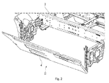
- Fig. 1 and 2 show a vehicle 2 with a side skirt 4.
- the vehicle 2 may be a motor vehicle such as a truck, also called a lorry, designed to transport cargo, or a tractor unit for pulling semi-trailers. Further, the vehicle 2 may be an unpowered vehicle towed by a powered vehicle for the transport of goods and materials.
- a motor vehicle such as a truck, also called a lorry, designed to transport cargo, or a tractor unit for pulling semi-trailers. Further, the vehicle 2 may be an unpowered vehicle towed by a powered vehicle for the transport of goods and materials.
- the side skirt 4 or trailer skirt is a device affixed to the underside of the vehicle 2 for the purpose of reducing aerodynamic drag caused by air turbulence.
- the side skirt 4 is a panel affixed to the lower side edge of the vehicle 2 running most of the length of the vehicle 2 and filling the gap between the forward and rear axles.
- the side skirt 4 is typically constructed of aluminum, plastic, or fiberglass, with plastic the most resistant to damage from side or bottom impacts.
- the side skirt 4 is pivotable attached to the vehicle 2 and can be moved from a first position I, e.g. a closed or driving position (see Fig. 1 ) to a second position II, e.g. an open position (see Fig. 2 ).
- a looking mechanism is provided (not shown in Fig. 1 and 2 ) which will be explained with reference to Fig. 3 and 4 .
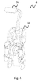
- Fig. 3 and 4 show the looking mechanism 6.
- the looking mechanism 6 comprises in a preferred embodiment a main hook member 8, a secondary hook member 10, a main counterpart member 12, a secondary counterpart member 14, a handle 16, a pin 18, a main spring 20, a secondary spring 22, a coupling hook member 24, a coupling counterpart member 26, a mount bracket 32 and a washer 34.
- the mount bracket 32 comprises a welded nut 40 to fix at the vehicle 2 with a welded nut 40, and comprises further bores through which the pin 18 extends.
- the pin 18 carry the main hook member 8, the secondary hook member 10, the main spring 20, the secondary spring 22, and the washer 34 wherein the main hook member 8 and the secondary hook member 10 are pivotable mounted on the pin 18 to pivot around longitudinal axis of the pin 18.
- the washer 34 is arranged on the pin 18 between the main hook member 8 and the secondary hook member 10.
- the main spring 20 is fixed with one of its ends at the mount bracket 32 and the other end is in engagement with the main hook member 8. Therefore, spring tension of the main spring 20 is transferred to the main hook member 8.
- the secondary spring 22 is fixed with one of its ends at the mount bracket 32 and the other end is in engagement with the secondary hook member 10. Therefore, spring tension of the secondary spring 22 is transferred to the secondary hook member 10.
- the main hook member 8 can be brought in engagement with the main counterpart member 12 to fix the side skirt 4 in the first position I and can be disengaged to allow a movement of the side skirt 2 from the first position I to the second position II.
- the handle 16 is fixed at the secondary hook member 10 to allow a user to move the secondary hook member 10 easily.
- the secondary hook member 10 comprises a coupling hook member 24 and the main hook member 8 comprises a coupling counterpart member 26.
- the coupling hook member 24 could be brought in engagement with the coupling counterpart member 26.
- a force is transferred from the handle 16 to the main hook member 8 to disengage the main hook member 8 from the main counterpart member 12.
- the main hook member 8 and the secondary hook member 10 comprise each a respective start up-slope 36, 38.
- the respective start up-slopes 36, 38 will cause the main counterpart member 12 and the secondary counterpart member 14 to move away to allow the main hook member 8 and secondary hook member 10 to pass its respective counterpart members 12, 14.
- the main counterpart member 12 is provided with a rubber part 36 at its tip. Additionally, the secondary counterpart member 14 is provided with a rubber part 38 at its tip to reduce such impacts, too.
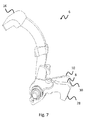
- Fig. 5 , 6 and 7 show the looking mechanism 6 without the main counterpart member 12 and the secondary counterpart member 14, wherein Fig. 7 shows the looking mechanism 6 without the mount bracket 32.
- Fig. 5 shows a position in which the main hook member 12 is in engagement with the main counterpart member 12 and the secondary hook member 10 is in engagement with the secondary counterpart member 14. Accordingly, the main hook member 8 and the secondary hook member 10 fix the side skirt 4 in the first position I (see Fig. 1 ).
- a user pulls the handle 16 in a direction D. This cause in a first step a movement of the secondary hook member 10, e.g. a lifting as shown in Fig. 6 , to disengage the secondary hook member 10 from the secondary counterpart member 14.
- the looking mechanism 6 is unlock and a user can pivot the side skirt 4 from the first position I to the second position II.
Landscapes
- Engineering & Computer Science (AREA)
- Mechanical Engineering (AREA)
- Structural Engineering (AREA)
- Chemical & Material Sciences (AREA)
- Combustion & Propulsion (AREA)
- Transportation (AREA)
- Lock And Its Accessories (AREA)
Abstract
Description
- The invention relates to a locking mechanism for a side skirt of a vehicle. Further, the invention relates to a side skirt with such a locking mechanism and a vehicle with such a side skirt.
- A locking mechanism of a side skirt of a vehicle uses a simple extension cord lock mechanism which is mounted on the side skirt mount bracket. To unlock a user had to pull the extension cord to himself and for locking the side skirt panel he had to be pushed forward and down.
- However, such an extension cord mechanism needed much effort and strength. Also since the cord is exposed external effects it could be easily harmed. Further, the mechanism made squeak noises when unlocking.
-
US 2014 / 0028055 A1 discloses a side skirt mounting apparatus. The apparatus according toUS 2014 / 0028055 A1 includes a side skirt that may be installed to be supported by a one-touch locker in an upper portion thereof and a hinge in a lower portion thereof. The locker includes an upper bracket, a lower bracket, a skirt frame to which the upper bracket and the lower bracket may be engaged, a shaft installed to slideably penetrate the upper and lower brackets and to be selectively inserted into a hole formed to a side skirt bracket, and an elastic member mounted on an outer circumference of the shaft between the upper and lower brackets to elastically support the shaft. -
CN 202847817 U discloses a lateral skirt board locking mechanism. The lateral skirt board locking mechanism comprises a lateral skirt board support, a lateral skirt board connection frame, a lateral skirt board assembling frame, clamping hook members, elastic devices, a hasp and a hook member. The lateral skirt board connection frame is connected with the lateral skirt board support through the hasp and the hook member for providing locking force. The middle portion of the lateral skirt board support is mutually clamped with a first elastic device in the middle of the skirt board assembling frame through a first clamping hook member for providing supporting force, and simultaneously the first elastic device has elasticity and can have buffering effect on contacting of the lateral skirt board support and the first elastic device. The bottom of the lateral skirt board support is clamped with a second elastic device at the bottom of the lateral skirt board assembling frame to provide reverse tension, and simultaneously the second elastic device has elasticity and can have buffering effect on contacting of the lateral skirt board support and the second elastic device to finally achieve locking of the lateral skirt board device. - However, there are no safety measurements in the mechanisms according to the prior art. This made it possible for the side skirt panel to loose from the lock in driving position. Since the side skirt panel is big it could cause risky and life threatening situations.
- It is therefore an object of the invention to improve the lock quality of such a locking mechanism.
- A locking mechanism for a side skirt of a vehicle according to the invention comprises a main hook member and a secondary hook member. The locking mechanism allows a movement of the side skirt from a first position to an second position if the main hook member and a main counterpart member and the secondary hook member and the secondary counterpart member are each not in engagement, wherein the locking mechanism fix the side skirt in the first position, if the main hook member is in engagement with the main counterpart member and/or the secondary hook member is in engagement with the secondary counterpart member. Further, the secondary hook member is adapted to transfer a force to the main hook member to move the main hook member to disengage the main hook member from the main counterpart member. The main hook member and the secondary hook member provides a two-step locking mechanism improving the lock quality and eliminating the squeak sound as well as user comfort by improving the lock handle. Due to having a safety secondary lock until any force required to unlock is applied the lock mechanism continue to work. This eliminates the health and environment risk of the side skirt panel while driving.
- In a preferred embodiment the looking mechanism comprises a handle to disengage the main hook member from the main counterpart member and to disengage the secondary hook member from the secondary counterpart member. Thus, the lock handle and looking mechanism can be altered to be used commonly through the lock positions. This in turn increases user satisfaction.
- In a preferred embodiment the handle is pivotable mounted on a pin. Thus, turning the handle about an axis of the pin allow the looking mechanism to have small dimension and makes it easy for a user to apply the necessary amount of power to bring the main hook member and the secondary hook member out of engagement.
- In a preferred embodiment a main spring is provided pressing the main hock in engagement with the main counterpart member. Thus, the lock safety is increased since the force provided by the main spring maintains the engagement of the main hook member and the main counterpart member.
- In a preferred embodiment a secondary spring is provided pressing the secondary hook member in engagement with the secondary counterpart member. Thus, the lock safety is increased since the force provided by the secondary spring maintains the engagement of the secondary hook member and the secondary counterpart member.
- In a preferred embodiment the secondary hook member comprises a coupling hook member and the main hook member comprises a coupling counterpart member, wherein the coupling hook member in engagement with the coupling counterpart member transfers the force from the handle to the main hook member to disengage the main hook member from the main counterpart member. Thus, a two-step locking mechanism is provided with only one handle to actuate to bring the main hook member and the secondary hook member out of engagement.
- In a preferred embodiment the looking mechanism is adapted to disengage firstly the secondary hook member from the secondary counterpart member, and to disengage later on the main hook member from the main counterpart member. Accordingly, a movement of the handle disengages the secondary hook member from the secondary counterpart member. When the secondary hook member is disengaged from the secondary counterpart member, a further movement of the handle disengages the main hook member from the main counterpart member. Thus, in a first step the main counterpart member and the secondary hook member will be bringing out of engagement. When, in second step the secondary hook member and the secondary counterpart member will bring out of engagement.
- In a preferred embodiment the main hook member and/or the secondary hook member comprise a startup-slope. When returning the side skirt from the second position to the first position the respective start up-slopes will cause the respective counterpart members to move away to allow the main hook member and/or secondary hook member to pass the respective counterpart members. Thus, the locking mechanism is easy to handle.
- Further, the invention relates to a side skirt with such a locking mechanism and a vehicle with such side skirt.
- An example of the invention will now be described with reference to the following drawings:
- Fig. 1
- shows a side skirt in a first position,
- Fig. 2
- shows the side skirt of
Fig. 1 in a second position, - Fig. 3
- shows the looking mechanism in an exploded view,
- Fig. 4
- shows the looking mechanism in an assembled view,
- Fig. 5
- show the looking mechanism of
Fig. 4 with the main hook member and the secondary hook member in a first position, - Fig. 6
- shows the looking mechanism of
Fig. 4 with the main hook member and the secondary hook member in a second position. - Fig. 7
- shows the looking mechanism of
Fig. 4 with the main hook member and the secondary hook member in a third position. -
Fig. 1 and2 show avehicle 2 with a side skirt 4. - The
vehicle 2 may be a motor vehicle such as a truck, also called a lorry, designed to transport cargo, or a tractor unit for pulling semi-trailers. Further, thevehicle 2 may be an unpowered vehicle towed by a powered vehicle for the transport of goods and materials. - The side skirt 4 or trailer skirt is a device affixed to the underside of the
vehicle 2 for the purpose of reducing aerodynamic drag caused by air turbulence. - The side skirt 4 is a panel affixed to the lower side edge of the
vehicle 2 running most of the length of thevehicle 2 and filling the gap between the forward and rear axles. The side skirt 4 is typically constructed of aluminum, plastic, or fiberglass, with plastic the most resistant to damage from side or bottom impacts. - The side skirt 4 is pivotable attached to the
vehicle 2 and can be moved from a first position I, e.g. a closed or driving position (seeFig. 1 ) to a second position II, e.g. an open position (seeFig. 2 ). To fix the side skirt in the first position I and to prevent the side skirt 4 from loosening a looking mechanism is provided (not shown inFig. 1 and2 ) which will be explained with reference toFig. 3 and4 . -
Fig. 3 and4 show the lookingmechanism 6. - The looking
mechanism 6 comprises in a preferred embodiment amain hook member 8, asecondary hook member 10, amain counterpart member 12, asecondary counterpart member 14, ahandle 16, apin 18, amain spring 20, asecondary spring 22, a coupling hook member 24, acoupling counterpart member 26, amount bracket 32 and awasher 34. - The
mount bracket 32 comprises a weldednut 40 to fix at thevehicle 2 with a weldednut 40, and comprises further bores through which thepin 18 extends. Thepin 18 carry themain hook member 8, thesecondary hook member 10, themain spring 20, thesecondary spring 22, and thewasher 34 wherein themain hook member 8 and thesecondary hook member 10 are pivotable mounted on thepin 18 to pivot around longitudinal axis of thepin 18. - The
washer 34 is arranged on thepin 18 between themain hook member 8 and thesecondary hook member 10. - The
main spring 20 is fixed with one of its ends at themount bracket 32 and the other end is in engagement with themain hook member 8. Therefore, spring tension of themain spring 20 is transferred to themain hook member 8. - The
secondary spring 22 is fixed with one of its ends at themount bracket 32 and the other end is in engagement with thesecondary hook member 10. Therefore, spring tension of thesecondary spring 22 is transferred to thesecondary hook member 10. - The
main hook member 8 can be brought in engagement with themain counterpart member 12 to fix the side skirt 4 in the first position I and can be disengaged to allow a movement of theside skirt 2 from the first position I to the second position II. - The
handle 16 is fixed at thesecondary hook member 10 to allow a user to move thesecondary hook member 10 easily. - The
secondary hook member 10 comprises a coupling hook member 24 and themain hook member 8 comprises acoupling counterpart member 26. The coupling hook member 24 could be brought in engagement with thecoupling counterpart member 26. When in engagement, a force is transferred from thehandle 16 to themain hook member 8 to disengage themain hook member 8 from themain counterpart member 12. - The
main hook member 8 and thesecondary hook member 10 comprise each a respective start up-slope slopes main counterpart member 12 and thesecondary counterpart member 14 to move away to allow themain hook member 8 andsecondary hook member 10 to pass itsrespective counterpart members - To reduce impacts caused by abutting of the
main hook member 8 on themain counterpart member 12 themain counterpart member 12 is provided with arubber part 36 at its tip. Additionally, thesecondary counterpart member 14 is provided with arubber part 38 at its tip to reduce such impacts, too. -
Fig. 5 ,6 and7 show the lookingmechanism 6 without themain counterpart member 12 and thesecondary counterpart member 14, whereinFig. 7 shows the lookingmechanism 6 without themount bracket 32. -
Fig. 5 shows a position in which themain hook member 12 is in engagement with themain counterpart member 12 and thesecondary hook member 10 is in engagement with thesecondary counterpart member 14. Accordingly, themain hook member 8 and thesecondary hook member 10 fix the side skirt 4 in the first position I (seeFig. 1 ). - To unlock the looking mechanism 6 a user pulls the
handle 16 in a direction D. This cause in a first step a movement of thesecondary hook member 10, e.g. a lifting as shown inFig. 6 , to disengage thesecondary hook member 10 from thesecondary counterpart member 14. - Further pulling the
handle 16 in the direction D cause in a second step a movement of themain hook member 8, since the coupling hook member 24 abuts on thecoupling counterpart member 26 and transfers force from thehandle 16 to themain hook member 8. As a result themain hook member 8 is moved, e.g. lifted as shown inFig. 7 , to disengage themain hook member 8 from themain counterpart member 12. - After the second step the looking
mechanism 6 is unlock and a user can pivot the side skirt 4 from the first position I to the second position II. - When the side skirt 4 is returned from the second position I to the first position I first the
main counterpart member 12 will abut on themain hook member 8, followed by thesecondary counterpart member 14 abutting on thesecondary hook member 10. - The shocks caused by the abutting of the
main counterpart member 12 and thesecondary counterpart member 14 on theirrespective hook members rubber parts slopes main hook member 8 and thesecondary hook member 10 will cause therespective counterpart members main hook member 10 and thesecondary hook member 12 to pass theirrespective counterpart members mechanism 6. -
- 2
- vehicle
- 4
- side skirt
- 6
- looking mechanism
- 8
- main hook member
- 10
- secondary hook member
- 12
- main counterpart member
- 14
- secondary counterpart member
- 16
- handle
- 18
- pin
- 20
- main spring
- 22
- secondary spring
- 24
- coupling hook member
- 26
- coupling counterpart member
- 28
- startup-slope
- 30
- startup-slope
- 32
- mount bracket
- 34
- washer
- 36
- rubber part
- 38
- rubber part
- 40
- weld nut
- D
- direction
Claims (10)
- Locking mechanism (6) for a side skirt (4) of a vehicle (2), wherein the locking mechanism (6) comprises a main hook member (8) and a secondary hook member (10), wherein the locking mechanism (6) allows a movement of the side skirt (4) from a first position (I) to an second position (II) if the main hook member (8) and a main counterpart member (12) and the secondary hook member (10) and a secondary counterpart member (14) are each not in engagement, and wherein the locking mechanism (6) fix the side skirt (4) in the first position (I), if the main hook member (8) is in engagement with the main counterpart member (12) and/or the secondary hook member (10) is in engagement with the secondary counterpart member (14), wherein the secondary hook member (10) is adapted to transfer a force to the main hook member (8) to move the main hook member (8) to disengage the main hook member (8) from the main counterpart member (12).
- Locking mechanism (6) according to claim 1, wherein the looking mechanism (6) comprises a handle (16) to disengage the main hook member (8) from the main counterpart member (12) and disengage the secondary hook member (10) from the secondary counterpart member (12).
- Locking mechanism (6) according to claim 2, wherein the handle (16) is pivotable mounted on a pin (18).
- Locking mechanism (6) according to claim 1, 2, or 3, wherein a main spring (20) is provided pressing the main hock (8) in engagement with the main counterpart member (12).
- Locking mechanism (6) according to one of the claims 1 to 4, wherein a secondary spring (22) is provided pressing the secondary hook member (10) in engagement with the secondary counterpart member (14).
- Locking mechanism (6) according to one of the claims 1 to 5, wherein the secondary hook member (10) comprises a coupling hook member (24) and the main hook member (8) comprises a coupling counterpart member (26), wherein the coupling hook member (24) in engagement with the coupling counterpart member (26) transfers the force from the handle (16) to the main hook member (8) to disengage the main hook member (8) from the main counterpart member (12).
- Locking mechanism (6) according to one of the claims 1 to 6, wherein the looking mechanism (6) is adapted to disengage firstly the secondary hook member (10) from the secondary counterpart member (14), and to disengage later on the main hook member (8) from the main counterpart member (12).
- Locking mechanism (6) according to one of the claims 1 to 7, wherein the main hook member (8) and/or the secondary hook member (10) comprise a startup-slope (28, 30).
- Side skirt (4) with a locking mechanism (6) according to one of the claims 1 to 8.
- Vehicle (2) with a side skirt (4) according to claim 9.
Priority Applications (1)
| Application Number | Priority Date | Filing Date | Title |
|---|---|---|---|
| EP15175404.1A EP3115282B1 (en) | 2015-07-06 | 2015-07-06 | Locking mechanism for a side skirt |
Applications Claiming Priority (1)
| Application Number | Priority Date | Filing Date | Title |
|---|---|---|---|
| EP15175404.1A EP3115282B1 (en) | 2015-07-06 | 2015-07-06 | Locking mechanism for a side skirt |
Publications (2)
| Publication Number | Publication Date |
|---|---|
| EP3115282A1 true EP3115282A1 (en) | 2017-01-11 |
| EP3115282B1 EP3115282B1 (en) | 2018-12-19 |
Family
ID=53514069
Family Applications (1)
| Application Number | Title | Priority Date | Filing Date |
|---|---|---|---|
| EP15175404.1A Not-in-force EP3115282B1 (en) | 2015-07-06 | 2015-07-06 | Locking mechanism for a side skirt |
Country Status (1)
| Country | Link |
|---|---|
| EP (1) | EP3115282B1 (en) |
Cited By (6)
| Publication number | Priority date | Publication date | Assignee | Title |
|---|---|---|---|---|
| SE1751043A1 (en) * | 2017-08-31 | 2019-03-01 | Scania Cv Ab | Support Arrangement, Body Panel, and Vehicle |
| SE1751165A1 (en) * | 2017-09-20 | 2019-03-21 | Scania Cv Ab | Body Panel Fastening Arrangement, Body Panel, and Vehicle |
| CN110805368A (en) * | 2018-08-06 | 2020-02-18 | 崇州市瑞杰汽修有限公司 | Passenger vehicle based on negative ion generating device and capable of purifying air |
| CN112644529A (en) * | 2021-01-04 | 2021-04-13 | 株洲时代新材料科技股份有限公司 | Method for improving fatigue resistance of lower skirt plate of cab and lower skirt plate of cab |
| CN116654103A (en) * | 2022-12-01 | 2023-08-29 | 奥动新能源汽车科技有限公司 | Protective device for commercial vehicle and commercial vehicle |
| CN116905913A (en) * | 2023-07-12 | 2023-10-20 | 青岛鸿裕吉轨道交通装备有限公司 | Apron board locking device |
Citations (5)
| Publication number | Priority date | Publication date | Assignee | Title |
|---|---|---|---|---|
| US20080129079A1 (en) * | 2006-11-17 | 2008-06-05 | Freightliner Llc, | Selectively removable side fairing for a vehicle |
| CN202847817U (en) | 2012-10-25 | 2013-04-03 | 中海石油气电集团有限责任公司 | Lateral skirtboard locking mechanism |
| JP2013119302A (en) * | 2011-12-07 | 2013-06-17 | Daimler Ag | Side skirt device for truck |
| US20140028055A1 (en) | 2012-07-27 | 2014-01-30 | Hyundai Motor Company | Side skirt for truck |
| US20150069784A1 (en) * | 2013-09-12 | 2015-03-12 | Hyundai Motor Company | Apparatus for opening and closing side skirt of truck |
-
2015
- 2015-07-06 EP EP15175404.1A patent/EP3115282B1/en not_active Not-in-force
Patent Citations (5)
| Publication number | Priority date | Publication date | Assignee | Title |
|---|---|---|---|---|
| US20080129079A1 (en) * | 2006-11-17 | 2008-06-05 | Freightliner Llc, | Selectively removable side fairing for a vehicle |
| JP2013119302A (en) * | 2011-12-07 | 2013-06-17 | Daimler Ag | Side skirt device for truck |
| US20140028055A1 (en) | 2012-07-27 | 2014-01-30 | Hyundai Motor Company | Side skirt for truck |
| CN202847817U (en) | 2012-10-25 | 2013-04-03 | 中海石油气电集团有限责任公司 | Lateral skirtboard locking mechanism |
| US20150069784A1 (en) * | 2013-09-12 | 2015-03-12 | Hyundai Motor Company | Apparatus for opening and closing side skirt of truck |
Cited By (8)
| Publication number | Priority date | Publication date | Assignee | Title |
|---|---|---|---|---|
| SE1751043A1 (en) * | 2017-08-31 | 2019-03-01 | Scania Cv Ab | Support Arrangement, Body Panel, and Vehicle |
| SE1751165A1 (en) * | 2017-09-20 | 2019-03-21 | Scania Cv Ab | Body Panel Fastening Arrangement, Body Panel, and Vehicle |
| SE541219C2 (en) * | 2017-09-20 | 2019-05-07 | Scania Cv Ab | Body Panel Fastening Arrangement, Body Panel, and Vehicle |
| CN110805368A (en) * | 2018-08-06 | 2020-02-18 | 崇州市瑞杰汽修有限公司 | Passenger vehicle based on negative ion generating device and capable of purifying air |
| CN112644529A (en) * | 2021-01-04 | 2021-04-13 | 株洲时代新材料科技股份有限公司 | Method for improving fatigue resistance of lower skirt plate of cab and lower skirt plate of cab |
| CN116654103A (en) * | 2022-12-01 | 2023-08-29 | 奥动新能源汽车科技有限公司 | Protective device for commercial vehicle and commercial vehicle |
| CN116905913A (en) * | 2023-07-12 | 2023-10-20 | 青岛鸿裕吉轨道交通装备有限公司 | Apron board locking device |
| CN116905913B (en) * | 2023-07-12 | 2025-08-26 | 青岛鸿裕吉轨道交通装备有限公司 | Skirt locking device |
Also Published As
| Publication number | Publication date |
|---|---|
| EP3115282B1 (en) | 2018-12-19 |
Similar Documents
| Publication | Publication Date | Title |
|---|---|---|
| EP3115282B1 (en) | Locking mechanism for a side skirt | |
| US5085408A (en) | Trailer connecting guide | |
| US9381863B2 (en) | Dog step attachment for receiver hitch of pickup truck | |
| US20070252360A1 (en) | Trailer hitch assembly | |
| US6896282B1 (en) | Tow hook replacement hitch | |
| CA2792486C (en) | Hitch apparatus for vehicles | |
| US7594641B2 (en) | Hitch installation hoist | |
| US20210237662A1 (en) | Vehicle comprising a driver cab and a monitoring device for monitoring a front dead angle area and monitoring device for such vehicle | |
| US9862243B2 (en) | Removable trailer tow hitch | |
| US20150084304A1 (en) | Extendable step for a truck | |
| US2978260A (en) | Dismountable trailer hitch | |
| US11097648B2 (en) | Method and apparatus for operating trailer jacks | |
| CN104334376B (en) | For the automatic locking system of vehicle traction component | |
| US2789834A (en) | Trailer hitch load equalizer | |
| CA2866442A1 (en) | Safety chain tie down apparatus | |
| US20110291385A1 (en) | Apparatus for Universal Rear Impact Guard Connection Adapter Plate | |
| KR101467254B1 (en) | wiper for vehicle | |
| US20070262107A1 (en) | Cargo carrier having a door with a lift-assisting hinge apparatus | |
| US9032633B2 (en) | Method and apparatus for repositioning a tandem axle assembly of a trailer | |
| EP2383077A2 (en) | A multifunctional portable device for use with vehicles | |
| CN208760513U (en) | car and its side steps | |
| US2838325A (en) | Safety jackknife apparatus | |
| US20240359751A1 (en) | Work Vehicle | |
| KR100462680B1 (en) | Control unit for tilting a cab of a truck | |
| AU2008100640A4 (en) | Trailer winch |
Legal Events
| Date | Code | Title | Description |
|---|---|---|---|
| PUAI | Public reference made under article 153(3) epc to a published international application that has entered the european phase |
Free format text: ORIGINAL CODE: 0009012 |
|
| STAA | Information on the status of an ep patent application or granted ep patent |
Free format text: STATUS: THE APPLICATION HAS BEEN PUBLISHED |
|
| AK | Designated contracting states |
Kind code of ref document: A1 Designated state(s): AL AT BE BG CH CY CZ DE DK EE ES FI FR GB GR HR HU IE IS IT LI LT LU LV MC MK MT NL NO PL PT RO RS SE SI SK SM TR |
|
| AX | Request for extension of the european patent |
Extension state: BA ME |
|
| STAA | Information on the status of an ep patent application or granted ep patent |
Free format text: STATUS: REQUEST FOR EXAMINATION WAS MADE |
|
| 17P | Request for examination filed |
Effective date: 20170711 |
|
| RBV | Designated contracting states (corrected) |
Designated state(s): AL AT BE BG CH CY CZ DE DK EE ES FI FR GB GR HR HU IE IS IT LI LT LU LV MC MK MT NL NO PL PT RO RS SE SI SK SM TR |
|
| STAA | Information on the status of an ep patent application or granted ep patent |
Free format text: STATUS: EXAMINATION IS IN PROGRESS |
|
| 17Q | First examination report despatched |
Effective date: 20180329 |
|
| GRAP | Despatch of communication of intention to grant a patent |
Free format text: ORIGINAL CODE: EPIDOSNIGR1 |
|
| STAA | Information on the status of an ep patent application or granted ep patent |
Free format text: STATUS: GRANT OF PATENT IS INTENDED |
|
| RIC1 | Information provided on ipc code assigned before grant |
Ipc: B62D 35/00 20060101AFI20180824BHEP Ipc: E05C 3/14 20060101ALI20180824BHEP Ipc: E05B 63/14 20060101ALI20180824BHEP Ipc: E05C 3/34 20060101ALI20180824BHEP Ipc: E05B 15/00 20060101ALI20180824BHEP Ipc: E05B 83/22 20140101ALI20180824BHEP Ipc: E05B 77/38 20140101ALI20180824BHEP |
|
| INTG | Intention to grant announced |
Effective date: 20180918 |
|
| GRAS | Grant fee paid |
Free format text: ORIGINAL CODE: EPIDOSNIGR3 |
|
| GRAA | (expected) grant |
Free format text: ORIGINAL CODE: 0009210 |
|
| STAA | Information on the status of an ep patent application or granted ep patent |
Free format text: STATUS: THE PATENT HAS BEEN GRANTED |
|
| AK | Designated contracting states |
Kind code of ref document: B1 Designated state(s): AL AT BE BG CH CY CZ DE DK EE ES FI FR GB GR HR HU IE IS IT LI LT LU LV MC MK MT NL NO PL PT RO RS SE SI SK SM TR |
|
| REG | Reference to a national code |
Ref country code: GB Ref legal event code: FG4D |
|
| REG | Reference to a national code |
Ref country code: CH Ref legal event code: EP |
|
| REG | Reference to a national code |
Ref country code: IE Ref legal event code: FG4D |
|
| REG | Reference to a national code |
Ref country code: DE Ref legal event code: R096 Ref document number: 602015021766 Country of ref document: DE |
|
| REG | Reference to a national code |
Ref country code: AT Ref legal event code: REF Ref document number: 1078373 Country of ref document: AT Kind code of ref document: T Effective date: 20190115 |
|
| REG | Reference to a national code |
Ref country code: NL Ref legal event code: MP Effective date: 20181219 |
|
| PG25 | Lapsed in a contracting state [announced via postgrant information from national office to epo] |
Ref country code: LV Free format text: LAPSE BECAUSE OF FAILURE TO SUBMIT A TRANSLATION OF THE DESCRIPTION OR TO PAY THE FEE WITHIN THE PRESCRIBED TIME-LIMIT Effective date: 20181219 Ref country code: NO Free format text: LAPSE BECAUSE OF FAILURE TO SUBMIT A TRANSLATION OF THE DESCRIPTION OR TO PAY THE FEE WITHIN THE PRESCRIBED TIME-LIMIT Effective date: 20190319 Ref country code: FI Free format text: LAPSE BECAUSE OF FAILURE TO SUBMIT A TRANSLATION OF THE DESCRIPTION OR TO PAY THE FEE WITHIN THE PRESCRIBED TIME-LIMIT Effective date: 20181219 Ref country code: LT Free format text: LAPSE BECAUSE OF FAILURE TO SUBMIT A TRANSLATION OF THE DESCRIPTION OR TO PAY THE FEE WITHIN THE PRESCRIBED TIME-LIMIT Effective date: 20181219 Ref country code: BG Free format text: LAPSE BECAUSE OF FAILURE TO SUBMIT A TRANSLATION OF THE DESCRIPTION OR TO PAY THE FEE WITHIN THE PRESCRIBED TIME-LIMIT Effective date: 20190319 Ref country code: HR Free format text: LAPSE BECAUSE OF FAILURE TO SUBMIT A TRANSLATION OF THE DESCRIPTION OR TO PAY THE FEE WITHIN THE PRESCRIBED TIME-LIMIT Effective date: 20181219 |
|
| REG | Reference to a national code |
Ref country code: LT Ref legal event code: MG4D |
|
| REG | Reference to a national code |
Ref country code: AT Ref legal event code: MK05 Ref document number: 1078373 Country of ref document: AT Kind code of ref document: T Effective date: 20181219 |
|
| PG25 | Lapsed in a contracting state [announced via postgrant information from national office to epo] |
Ref country code: RS Free format text: LAPSE BECAUSE OF FAILURE TO SUBMIT A TRANSLATION OF THE DESCRIPTION OR TO PAY THE FEE WITHIN THE PRESCRIBED TIME-LIMIT Effective date: 20181219 Ref country code: SE Free format text: LAPSE BECAUSE OF FAILURE TO SUBMIT A TRANSLATION OF THE DESCRIPTION OR TO PAY THE FEE WITHIN THE PRESCRIBED TIME-LIMIT Effective date: 20181219 Ref country code: GR Free format text: LAPSE BECAUSE OF FAILURE TO SUBMIT A TRANSLATION OF THE DESCRIPTION OR TO PAY THE FEE WITHIN THE PRESCRIBED TIME-LIMIT Effective date: 20190320 Ref country code: AL Free format text: LAPSE BECAUSE OF FAILURE TO SUBMIT A TRANSLATION OF THE DESCRIPTION OR TO PAY THE FEE WITHIN THE PRESCRIBED TIME-LIMIT Effective date: 20181219 |
|
| PG25 | Lapsed in a contracting state [announced via postgrant information from national office to epo] |
Ref country code: NL Free format text: LAPSE BECAUSE OF FAILURE TO SUBMIT A TRANSLATION OF THE DESCRIPTION OR TO PAY THE FEE WITHIN THE PRESCRIBED TIME-LIMIT Effective date: 20181219 |
|
| PG25 | Lapsed in a contracting state [announced via postgrant information from national office to epo] |
Ref country code: ES Free format text: LAPSE BECAUSE OF FAILURE TO SUBMIT A TRANSLATION OF THE DESCRIPTION OR TO PAY THE FEE WITHIN THE PRESCRIBED TIME-LIMIT Effective date: 20181219 Ref country code: PL Free format text: LAPSE BECAUSE OF FAILURE TO SUBMIT A TRANSLATION OF THE DESCRIPTION OR TO PAY THE FEE WITHIN THE PRESCRIBED TIME-LIMIT Effective date: 20181219 Ref country code: IT Free format text: LAPSE BECAUSE OF FAILURE TO SUBMIT A TRANSLATION OF THE DESCRIPTION OR TO PAY THE FEE WITHIN THE PRESCRIBED TIME-LIMIT Effective date: 20181219 Ref country code: CZ Free format text: LAPSE BECAUSE OF FAILURE TO SUBMIT A TRANSLATION OF THE DESCRIPTION OR TO PAY THE FEE WITHIN THE PRESCRIBED TIME-LIMIT Effective date: 20181219 Ref country code: PT Free format text: LAPSE BECAUSE OF FAILURE TO SUBMIT A TRANSLATION OF THE DESCRIPTION OR TO PAY THE FEE WITHIN THE PRESCRIBED TIME-LIMIT Effective date: 20190419 |
|
| PG25 | Lapsed in a contracting state [announced via postgrant information from national office to epo] |
Ref country code: SK Free format text: LAPSE BECAUSE OF FAILURE TO SUBMIT A TRANSLATION OF THE DESCRIPTION OR TO PAY THE FEE WITHIN THE PRESCRIBED TIME-LIMIT Effective date: 20181219 Ref country code: RO Free format text: LAPSE BECAUSE OF FAILURE TO SUBMIT A TRANSLATION OF THE DESCRIPTION OR TO PAY THE FEE WITHIN THE PRESCRIBED TIME-LIMIT Effective date: 20181219 Ref country code: IS Free format text: LAPSE BECAUSE OF FAILURE TO SUBMIT A TRANSLATION OF THE DESCRIPTION OR TO PAY THE FEE WITHIN THE PRESCRIBED TIME-LIMIT Effective date: 20190419 Ref country code: SM Free format text: LAPSE BECAUSE OF FAILURE TO SUBMIT A TRANSLATION OF THE DESCRIPTION OR TO PAY THE FEE WITHIN THE PRESCRIBED TIME-LIMIT Effective date: 20181219 Ref country code: EE Free format text: LAPSE BECAUSE OF FAILURE TO SUBMIT A TRANSLATION OF THE DESCRIPTION OR TO PAY THE FEE WITHIN THE PRESCRIBED TIME-LIMIT Effective date: 20181219 |
|
| PGFP | Annual fee paid to national office [announced via postgrant information from national office to epo] |
Ref country code: FR Payment date: 20190621 Year of fee payment: 5 |
|
| REG | Reference to a national code |
Ref country code: DE Ref legal event code: R097 Ref document number: 602015021766 Country of ref document: DE |
|
| PLBE | No opposition filed within time limit |
Free format text: ORIGINAL CODE: 0009261 |
|
| STAA | Information on the status of an ep patent application or granted ep patent |
Free format text: STATUS: NO OPPOSITION FILED WITHIN TIME LIMIT |
|
| PG25 | Lapsed in a contracting state [announced via postgrant information from national office to epo] |
Ref country code: DK Free format text: LAPSE BECAUSE OF FAILURE TO SUBMIT A TRANSLATION OF THE DESCRIPTION OR TO PAY THE FEE WITHIN THE PRESCRIBED TIME-LIMIT Effective date: 20181219 Ref country code: AT Free format text: LAPSE BECAUSE OF FAILURE TO SUBMIT A TRANSLATION OF THE DESCRIPTION OR TO PAY THE FEE WITHIN THE PRESCRIBED TIME-LIMIT Effective date: 20181219 |
|
| PGFP | Annual fee paid to national office [announced via postgrant information from national office to epo] |
Ref country code: GB Payment date: 20190626 Year of fee payment: 5 Ref country code: DE Payment date: 20190617 Year of fee payment: 5 |
|
| 26N | No opposition filed |
Effective date: 20190920 |
|
| PG25 | Lapsed in a contracting state [announced via postgrant information from national office to epo] |
Ref country code: MC Free format text: LAPSE BECAUSE OF FAILURE TO SUBMIT A TRANSLATION OF THE DESCRIPTION OR TO PAY THE FEE WITHIN THE PRESCRIBED TIME-LIMIT Effective date: 20181219 Ref country code: SI Free format text: LAPSE BECAUSE OF FAILURE TO SUBMIT A TRANSLATION OF THE DESCRIPTION OR TO PAY THE FEE WITHIN THE PRESCRIBED TIME-LIMIT Effective date: 20181219 |
|
| REG | Reference to a national code |
Ref country code: CH Ref legal event code: PL |
|
| PG25 | Lapsed in a contracting state [announced via postgrant information from national office to epo] |
Ref country code: TR Free format text: LAPSE BECAUSE OF FAILURE TO SUBMIT A TRANSLATION OF THE DESCRIPTION OR TO PAY THE FEE WITHIN THE PRESCRIBED TIME-LIMIT Effective date: 20181219 |
|
| REG | Reference to a national code |
Ref country code: BE Ref legal event code: MM Effective date: 20190731 |
|
| PG25 | Lapsed in a contracting state [announced via postgrant information from national office to epo] |
Ref country code: LU Free format text: LAPSE BECAUSE OF NON-PAYMENT OF DUE FEES Effective date: 20190706 Ref country code: CH Free format text: LAPSE BECAUSE OF NON-PAYMENT OF DUE FEES Effective date: 20190731 Ref country code: LI Free format text: LAPSE BECAUSE OF NON-PAYMENT OF DUE FEES Effective date: 20190731 Ref country code: BE Free format text: LAPSE BECAUSE OF NON-PAYMENT OF DUE FEES Effective date: 20190731 |
|
| PG25 | Lapsed in a contracting state [announced via postgrant information from national office to epo] |
Ref country code: IE Free format text: LAPSE BECAUSE OF NON-PAYMENT OF DUE FEES Effective date: 20190706 |
|
| REG | Reference to a national code |
Ref country code: DE Ref legal event code: R119 Ref document number: 602015021766 Country of ref document: DE |
|
| GBPC | Gb: european patent ceased through non-payment of renewal fee |
Effective date: 20200706 |
|
| PG25 | Lapsed in a contracting state [announced via postgrant information from national office to epo] |
Ref country code: GB Free format text: LAPSE BECAUSE OF NON-PAYMENT OF DUE FEES Effective date: 20200706 Ref country code: FR Free format text: LAPSE BECAUSE OF NON-PAYMENT OF DUE FEES Effective date: 20200731 |
|
| PG25 | Lapsed in a contracting state [announced via postgrant information from national office to epo] |
Ref country code: CY Free format text: LAPSE BECAUSE OF FAILURE TO SUBMIT A TRANSLATION OF THE DESCRIPTION OR TO PAY THE FEE WITHIN THE PRESCRIBED TIME-LIMIT Effective date: 20181219 Ref country code: DE Free format text: LAPSE BECAUSE OF NON-PAYMENT OF DUE FEES Effective date: 20210202 |
|
| PG25 | Lapsed in a contracting state [announced via postgrant information from national office to epo] |
Ref country code: HU Free format text: LAPSE BECAUSE OF FAILURE TO SUBMIT A TRANSLATION OF THE DESCRIPTION OR TO PAY THE FEE WITHIN THE PRESCRIBED TIME-LIMIT; INVALID AB INITIO Effective date: 20150706 Ref country code: MT Free format text: LAPSE BECAUSE OF FAILURE TO SUBMIT A TRANSLATION OF THE DESCRIPTION OR TO PAY THE FEE WITHIN THE PRESCRIBED TIME-LIMIT Effective date: 20181219 |
|
| PG25 | Lapsed in a contracting state [announced via postgrant information from national office to epo] |
Ref country code: MK Free format text: LAPSE BECAUSE OF FAILURE TO SUBMIT A TRANSLATION OF THE DESCRIPTION OR TO PAY THE FEE WITHIN THE PRESCRIBED TIME-LIMIT Effective date: 20181219 |