EP3115218A1 - Liquid discharging apparatus - Google Patents
Liquid discharging apparatus Download PDFInfo
- Publication number
- EP3115218A1 EP3115218A1 EP16178948.2A EP16178948A EP3115218A1 EP 3115218 A1 EP3115218 A1 EP 3115218A1 EP 16178948 A EP16178948 A EP 16178948A EP 3115218 A1 EP3115218 A1 EP 3115218A1
- Authority
- EP
- European Patent Office
- Prior art keywords
- cleaning
- supporting surface
- medium
- transportation
- transportation belt
- Prior art date
- Legal status (The legal status is an assumption and is not a legal conclusion. Google has not performed a legal analysis and makes no representation as to the accuracy of the status listed.)
- Granted
Links
- 239000007788 liquid Substances 0.000 title claims abstract description 36
- 238000007599 discharging Methods 0.000 title claims abstract description 35
- 238000004140 cleaning Methods 0.000 claims abstract description 194
- 230000007246 mechanism Effects 0.000 claims abstract description 33
- 238000011109 contamination Methods 0.000 claims description 46
- 238000003825 pressing Methods 0.000 claims description 23
- 238000000034 method Methods 0.000 description 23
- 230000008569 process Effects 0.000 description 20
- 238000004804 winding Methods 0.000 description 15
- 238000012545 processing Methods 0.000 description 14
- 239000004744 fabric Substances 0.000 description 9
- 230000009471 action Effects 0.000 description 4
- 230000008859 change Effects 0.000 description 4
- 230000032258 transport Effects 0.000 description 4
- XLYOFNOQVPJJNP-UHFFFAOYSA-N water Substances O XLYOFNOQVPJJNP-UHFFFAOYSA-N 0.000 description 4
- 230000000694 effects Effects 0.000 description 3
- 238000011010 flushing procedure Methods 0.000 description 3
- 238000010438 heat treatment Methods 0.000 description 3
- 238000005299 abrasion Methods 0.000 description 2
- 239000000853 adhesive Substances 0.000 description 2
- 230000001070 adhesive effect Effects 0.000 description 2
- 230000003247 decreasing effect Effects 0.000 description 2
- 239000000835 fiber Substances 0.000 description 2
- 238000007781 pre-processing Methods 0.000 description 2
- 230000008901 benefit Effects 0.000 description 1
- 239000012459 cleaning agent Substances 0.000 description 1
- 238000005520 cutting process Methods 0.000 description 1
- 230000007423 decrease Effects 0.000 description 1
- 238000010586 diagram Methods 0.000 description 1
- 238000012423 maintenance Methods 0.000 description 1
- 238000012986 modification Methods 0.000 description 1
- 230000004048 modification Effects 0.000 description 1
- 238000004904 shortening Methods 0.000 description 1
- 238000012360 testing method Methods 0.000 description 1
- 238000011144 upstream manufacturing Methods 0.000 description 1
Images





Classifications
-
- B—PERFORMING OPERATIONS; TRANSPORTING
- B41—PRINTING; LINING MACHINES; TYPEWRITERS; STAMPS
- B41J—TYPEWRITERS; SELECTIVE PRINTING MECHANISMS, i.e. MECHANISMS PRINTING OTHERWISE THAN FROM A FORME; CORRECTION OF TYPOGRAPHICAL ERRORS
- B41J3/00—Typewriters or selective printing or marking mechanisms characterised by the purpose for which they are constructed
- B41J3/407—Typewriters or selective printing or marking mechanisms characterised by the purpose for which they are constructed for marking on special material
- B41J3/4078—Printing on textile
-
- B—PERFORMING OPERATIONS; TRANSPORTING
- B41—PRINTING; LINING MACHINES; TYPEWRITERS; STAMPS
- B41J—TYPEWRITERS; SELECTIVE PRINTING MECHANISMS, i.e. MECHANISMS PRINTING OTHERWISE THAN FROM A FORME; CORRECTION OF TYPOGRAPHICAL ERRORS
- B41J11/00—Devices or arrangements of selective printing mechanisms, e.g. ink-jet printers or thermal printers, for supporting or handling copy material in sheet or web form
- B41J11/007—Conveyor belts or like feeding devices
-
- B—PERFORMING OPERATIONS; TRANSPORTING
- B41—PRINTING; LINING MACHINES; TYPEWRITERS; STAMPS
- B41J—TYPEWRITERS; SELECTIVE PRINTING MECHANISMS, i.e. MECHANISMS PRINTING OTHERWISE THAN FROM A FORME; CORRECTION OF TYPOGRAPHICAL ERRORS
- B41J15/00—Devices or arrangements of selective printing mechanisms, e.g. ink-jet printers or thermal printers, specially adapted for supporting or handling copy material in continuous form, e.g. webs
- B41J15/04—Supporting, feeding, or guiding devices; Mountings for web rolls or spindles
- B41J15/048—Conveyor belts or like feeding devices
-
- B—PERFORMING OPERATIONS; TRANSPORTING
- B41—PRINTING; LINING MACHINES; TYPEWRITERS; STAMPS
- B41J—TYPEWRITERS; SELECTIVE PRINTING MECHANISMS, i.e. MECHANISMS PRINTING OTHERWISE THAN FROM A FORME; CORRECTION OF TYPOGRAPHICAL ERRORS
- B41J29/00—Details of, or accessories for, typewriters or selective printing mechanisms not otherwise provided for
- B41J29/17—Cleaning arrangements
-
- B—PERFORMING OPERATIONS; TRANSPORTING
- B65—CONVEYING; PACKING; STORING; HANDLING THIN OR FILAMENTARY MATERIAL
- B65H—HANDLING THIN OR FILAMENTARY MATERIAL, e.g. SHEETS, WEBS, CABLES
- B65H20/00—Advancing webs
- B65H20/06—Advancing webs by friction band
-
- B—PERFORMING OPERATIONS; TRANSPORTING
- B65—CONVEYING; PACKING; STORING; HANDLING THIN OR FILAMENTARY MATERIAL
- B65H—HANDLING THIN OR FILAMENTARY MATERIAL, e.g. SHEETS, WEBS, CABLES
- B65H2301/00—Handling processes for sheets or webs
- B65H2301/50—Auxiliary process performed during handling process
- B65H2301/53—Auxiliary process performed during handling process for acting on performance of handling machine
- B65H2301/531—Cleaning parts of handling machine
-
- B—PERFORMING OPERATIONS; TRANSPORTING
- B65—CONVEYING; PACKING; STORING; HANDLING THIN OR FILAMENTARY MATERIAL
- B65H—HANDLING THIN OR FILAMENTARY MATERIAL, e.g. SHEETS, WEBS, CABLES
- B65H2404/00—Parts for transporting or guiding the handled material
- B65H2404/20—Belts
- B65H2404/26—Particular arrangement of belt, or belts
- B65H2404/261—Arrangement of belts, or belt(s) / roller(s) facing each other for forming a transport nip
-
- B—PERFORMING OPERATIONS; TRANSPORTING
- B65—CONVEYING; PACKING; STORING; HANDLING THIN OR FILAMENTARY MATERIAL
- B65H—HANDLING THIN OR FILAMENTARY MATERIAL, e.g. SHEETS, WEBS, CABLES
- B65H2701/00—Handled material; Storage means
- B65H2701/10—Handled articles or webs
- B65H2701/17—Nature of material
- B65H2701/174—Textile; fibres
-
- B—PERFORMING OPERATIONS; TRANSPORTING
- B65—CONVEYING; PACKING; STORING; HANDLING THIN OR FILAMENTARY MATERIAL
- B65H—HANDLING THIN OR FILAMENTARY MATERIAL, e.g. SHEETS, WEBS, CABLES
- B65H2801/00—Application field
- B65H2801/03—Image reproduction devices
- B65H2801/12—Single-function printing machines, typically table-top machines
Definitions
- the present invention relates to a liquid discharging apparatus having a configuration in which a medium supporting surface of a transportation belt capable of transporting a medium while supporting the medium on the medium supporting surface is cleaned with a cleaning solution by a cleaning member.
- an ink jet recording apparatus as described in JP-A-11-192694 can be exemplified.
- JP-A-11-192694 discloses a technique of cleaning ink, dusts, and the like attached to a medium supporting surface of an endless belt with water and a cleaning brush.
- JP-A-11-192694 does not disclose or suggest the problem relating to lowering of the cleaning capability due to lowering of the environment temperature.
- An advantage of an aspect of the invention is to provide a liquid discharging apparatus having a configuration in which a medium supporting surface of a transportation belt is cleaned with a cleaning solution and a cleaning member, which is not easily influenced by lowering of an environment temperature.
- a liquid discharging apparatus includes a transportation belt that has a medium supporting surface and is capable of transporting a medium while supporting the medium on the medium supporting surface, a discharging head that discharges liquid onto the medium supported by the transportation belt, a cleaning mechanism that has a cleaning member making contact with the transportation belt so as to clean the medium supporting surface with a cleaning solution, a heater that supplies heat to a cleaning portion of the medium supporting surface by the cleaning member, and a controller that controls a cleaning temperature on the cleaning portion by driving the heater.
- the liquid discharging apparatus includes the heater that supplies heat to the cleaning portion of the medium supporting surface by the cleaning member and the controller that controls the cleaning temperature on the cleaning portion by driving the heater. Accordingly, control to increase the cleaning temperature on the cleaning portion can be performed. With this, even when the environment temperature lowers, the control is performed so as not to be influenced easily by the lowering of the environment temperature. That is to say, lowering of the cleaning capability can be suppressed even when the environment temperature lowers.
- the controller control the cleaning temperature based on information relating to an environment temperature.
- controls the cleaning temperature based on information relating to an environment temperature has the following meaning. That is, when the environment temperature is low and the temperature of the cleaning portion is also lowered so that a cleaning effect by the cleaning member is lowered, the controller controls to increase the cleaning temperature by driving the heater.
- the cleaning temperature is controlled based on the information relating to the environment temperature. Therefore, when the environment temperature lowers, the cleaning temperature can be increased automatically.
- the controller control the cleaning temperature on the cleaning portion by the cleaning member based on information relating to a contamination degree of the medium supporting surface.
- the expression "information relating to a contamination degree” includes information obtained by measuring the contamination degree directly, and physical amounts having correlations with change in the contamination degree, for example, information on the number of rotations of the transportation belt and the number of rotations of a motor for driving the transportation belt. Furthermore, the expression is also used to include an image data amount relating to a discharging amount of the liquid, a type of a fabric (whether or not the fabric is a type easy to be permeated with liquid, fiber density and so on) when the medium is a fabric, a method of performing preprocessing on the fabric (permeation processing or non-permeation processing), recording without margins or with margins, whether or not the medium supporting surface is used for a flushing region, and so on.
- control to increase the cleaning temperature is performed so as to enhance the cleaning capability. Accordingly, sufficient cleaning can be performed.
- the heater supply heat to the transportation belt.
- the cleaning temperature can be increased easily and effectively.
- the heater supply heat to the cleaning solution.
- the cleaning temperature can be increased easily and effectively.
- the heater supply heat to the cleaning member.
- the cleaning temperature can be increased easily and effectively.
- the controller adjust at least any one of a) a pressing force of the cleaning member, b) a rotating speed of the cleaning member, and c) a transportation speed of the transportation belt based on the information relating to the contamination degree of the medium supporting surface.
- adjust means that the controller increases/decreases the pressing force, the rotating speed, and/or the transportation speed, in other words, adjusts strength of a cleaning force of the cleaning member for the medium supporting surface.
- a transportation speed of the transportation belt is used to indicate a movement speed of the transportation belt when the belt moves continuously like a line printer or the like. It is also used to indicate the speed at which the belt moves and/or indicate a stop time (standby time) mainly when the transportation belt moves intermittently.
- the controller adjusts at least any one of a) the pressing force of the cleaning member, b) the rotating speed of the cleaning member, and c) the transportation speed of the transportation belt based on the information relating to the contamination degree of the medium supporting surface.
- the strength of the cleaning force of the cleaning member for the medium supporting surface can be controlled.
- the strength of the cleaning force of the cleaning member can be changed in accordance with the contamination degree of the medium supporting surface of the transportation belt.
- the cleaning force of the cleaning member becomes too large relative to the actual contamination level and the medium supporting surface is abraded can be solved. Furthermore, a problem that the cleaning force of the cleaning member becomes insufficient relative to the actual contamination level and the cleaning quality is lowered can be also solved. That is, the medium supporting surface can be cleaned with an appropriate strength of the cleaning force in accordance with the contamination degree. This can suppress the abrasion without lowering the cleaning quality.
- the controller execute adjustment of "a) the pressing force of the cleaning member" first based on the information relating to the contamination degree.
- the controller executes adjustment of "a) the pressing force of the cleaning member" first based on the information relating to the contamination degree. This makes it possible to adjust the strength of the cleaning force of the cleaning member for the medium supporting surface effectively and easily.
- the controller have a plurality of cleaning operation modes in which strengths of cleaning forces of the cleaning member for the medium supporting surface are different, and select and execute one of the plurality of cleaning operation modes based on the information.
- the controller selects and executes one of the plurality of cleaning operation modes in which strengths of the cleaning forces are different based on the information relating to the contamination degree. Therefore, a control configuration can be simplified.
- Fig. 1 is a schematic side view illustrating an ink jet recording apparatus 1 according to a first embodiment of the invention.
- the ink jet recording apparatus 1 in the embodiment includes a feeding portion 2.
- the feeding portion 2 can feed out a roll R1 of a recording medium P formed by a fabric medium in a roll form for recording, as an example.
- the ink jet recording apparatus 1 includes a transportation mechanism 3.
- the transportation mechanism 3 transports the recording medium P in a transportation direction A by an endless transportation belt 10.
- the transportation belt 10 supports the recording medium P on a medium supporting surface F to which an adhesive is attached. It should be noted that the adhesive may not be attached to the transportation belt.
- the ink jet recording apparatus 1 includes a recording mechanism 4.
- the recording mechanism 4 performs recording by causing a recording head 7 as a discharging head to reciprocate in a width direction (that is also as a width direction of the recording medium P) B of the transportation belt 10.
- the width direction B intersects with the transportation direction A of the recording medium P.
- the ink jet recording apparatus 1 in the embodiment includes a cleaning mechanism 15 for cleaning the transportation belt 10. Furthermore, the ink jet recording apparatus 1 includes a winding mechanism 18.
- the winding mechanism 18 includes a winding shaft 17 for winding the recording medium P therearound and a cutter 16 for cutting the recording medium P that is being wound.
- the feeding portion 2 includes a rotating shaft 5 also serving as a set position of the roll R1 of the recording medium P for recording.
- the feeding portion 2 has a configuration capable of feeding out the recording medium P to the transportation mechanism 3 from the roll R1 set on the rotating shaft 5 through a driven roller 6.
- the rotating shaft 5 rotates in a rotating direction C.
- the transportation mechanism 3 includes the transportation belt 10, a transportation driving roller 8, and a transportation driven roller 9.
- the transportation belt 10 transports the recording medium P that has been fed out from the feeding portion 2 while supporting the recording medium P.
- the transportation driving roller 8 and the transportation driven roller 9 move the transportation belt 10.
- the recording medium P is mounted on the transportation belt 10 at a position on the upstream side in the transportation direction A so as to be attached to the medium supporting surface F of the transportation belt 10 in a pressurized manner by a pressure roller 12.
- the transportation driving roller 8 rotates in the rotating direction C and the transportation belt 10 moves in a movement direction E, that is, is rotationally moved.
- the recording mechanism 4 includes the recording head 7, a carriage (not illustrated), and a carriage motor 26 ( Fig. 2 ).
- the recording head 7 discharges ink onto the recording medium P supported by the transportation belt 10 so as to perform recording.
- the recording head 7 is mounted on the carriage.
- the carriage motor 26 causes the carriage to reciprocate in the width direction B. It should be noted that in Fig. 1 , the width direction B is a perpendicular direction with respect to the plane of the paper on which Fig. 1 is illustrated.
- the recording mechanism 4 causes the recording head 7 to reciprocate for recording at the time of the recording. While the recording head 7 is being moved, the transportation mechanism 3 stops transportation of the recording medium P. In another expression, the reciprocation of the recording head 7 and the transportation of the recording medium P are alternately performed at the time of the recording. That is to say, the transportation mechanism 3 transports the recording medium P intermittently so as to correspond to the reciprocation of the recording head 7 at the time of the recording.
- the recording mechanism 4 has a configuration in which the recording head 7 is caused to reciprocate for recording. Note that the recording mechanism is not limited to having the configuration. Alternatively, the recording mechanism may include a what-is-called line head on which nozzle rows for discharging ink are provided in the width direction intersecting with the transportation direction A.
- the cleaning mechanism 15 of the transportation belt 10 includes a cleaning roller 13 as a cleaning member, a cleaning solution tank 14 accommodating a cleaning agent for cleaning the cleaning roller 13, and a cylinder 19 as a pressing portion that presses the cleaning roller 13 against the transportation belt 10.
- the cylinder 19 not only can press the cleaning roller 13 against the transportation belt 10 but also can separate the cleaning roller 13 from the transportation belt 10.
- the cleaning roller 13 is pressed against the transportation belt 10 by the cylinder 19.
- a controller 20 controls the pressing force thereof.
- the controller 20 is electrically connected to the cylinder 19, the feeding portion 2, the transportation mechanism 3, the recording mechanism 4, the cleaning mechanism 15, the winding mechanism 18, and the like and controls to transport the recording medium P intermittently so as to correspond to the reciprocation of the recording head 7.
- the cleaning roller 13 is formed so as to have a length in the width direction B that is longer than the length of the transportation belt 10 in the width direction B. This enables the cleaning roller 13 to clean overall the transportation belt 10 in the width direction B. Further, a wide contact surface of the transportation belt 10 can be cleaned, thereby suppressing cleaning unevenness in the transportation belt 10 effectively.
- the winding mechanism 18 is a mechanism for winding the recording medium P on which recording has been performed and that has been transported from the transportation mechanism 3 through a driven roller 11 around the winding shaft 17. That is to say, the winding mechanism 18 winds the recording medium P as a roll R2 by setting a paper tube or the like for winding on the winding shaft 17 and winding the recording medium P around it.
- the controller 20 controls operations of the cleaning mechanism 15 and the like. That is, the controller 20 is configured so as to adjust the pressing force of the cleaning roller 13 by the cylinder 19 based on information relating to the contamination degree of the medium supporting surface F. With this, the strength of the cleaning force of the cleaning roller 13 for the medium supporting surface F can be adjusted effectively and easily.
- the controller 20 may be configured so as to adjust the rotating speed of the cleaning roller 13 by a cleaning roller motor 37, which will be described later, based on the information relating to the contamination degree of the medium supporting surface F.
- the controller 20 may be configured so as to adjust the transportation speed of the transportation belt 10 by a transportation motor 27, which will be described later, based on the information relating to the contamination degree of the medium supporting surface F.
- a plurality of the adjustment targets may be combined.
- the controller 20 adjusts the pressing force of the cleaning roller 13, and then, adjusts the rotating speed of the cleaning roller 13 when the adjustment is not sufficient.
- a contamination detector 38 is provided.
- the contamination detector 38 measures the contamination degree of the medium supporting surface F directly.
- a contamination detector that irradiates the surface of the medium supporting surface F with laser beams so as to obtain the contamination degree based on attenuation of reflected light due to the contamination, and a contamination detector that image-captures the surface of the medium supporting surface F by a charge-coupled device (CCD) camera so as to obtain the contamination degree based on color change can be exemplified.
- CCD charge-coupled device
- the medium supporting surface F so as to obtain the contamination degree based on change of sound quality such as a frequency and an intensity due to the contamination can be exemplified.
- the information relating to the contamination degree may be defined using physical amounts having correlations with the change of the contamination degree, for example, the number of rotations of the transportation belt and the number of rotations of the motor for driving the transportation belt.
- the flushing is executed as a maintenance operation of the discharging head.
- the ink jet recording apparatus 1 in the embodiment further includes a heater 40 that supplies heat to a cleaning portion 39 ( Fig. 1 ) of the cleaning roller 13 for the medium supporting surface F.
- the heater 40 is provided on the cleaning solution tank 14, and is configured so as to heat a cleaning solution 41 therein and increase the temperature thereof.
- a place on which the heater 40 is provided is not limited to the cleaning solution tank 14.
- the controller 20 is configured to drive the heater 40 through a heater driving portion 43 ( Fig. 2 ) so as to control the cleaning temperature on the cleaning portion 39.
- the controller 20 is configured to control the cleaning temperature based on information relating to the environment temperature that is obtained by a temperature detector 42.
- cleaning temperature is a temperature of the cleaning portion 39 where the cleaning roller 13 cleans by making contact with the medium supporting surface F of the transportation belt 10 during cleaning.
- the cleaning temperature is determined by combining temperatures of respective members constituting the cleaning portion 39, such as a temperature of the cleaning solution 41 constituting a part of the cleaning mechanism 15, a temperature of the cleaning roller 13 itself, and a temperature of the medium supporting surface F of the transportation belt 10.
- the cleaning temperature is changed by changing the temperature of any one of the members constituting the cleaning portion 39, or the temperatures of equal to or more than two of the members.
- the controller 20 is provided with a central processing unit (CPU) 21 for controlling the ink jet recording apparatus 1 overall.
- the CPU 21 is connected to a read only memory (ROM) 23 and a random access memory (RAM) 24 through a system bus 22.
- the ROM 23 stores therein control programs of various types, which are executed by the CPU 21, and the like.
- the RAM 24 can store data temporarily.
- the CPU 21 is connected to a head driving portion 25 for driving the recording head 7 through the system bus 22.
- the CPU 21 is connected to a motor driving portion 32 through the system bus 22.
- the motor driving portion 32 is a portion for driving the carriage motor 26, the transportation motor 27, a feeding motor 28, a winding motor 29, and the cleaning roller motor 37.
- the carriage motor 26 is a motor for moving the carriage (not illustrated) on which the recording head 7 is mounted.
- the transportation motor 27 is a motor for driving the transportation driving roller 8.
- the feeding motor 28 is a rotating mechanism of the rotating shaft 5 and is a motor for driving the rotating shaft 5 for feeding out the recording medium P to the transportation mechanism 3.
- the winding motor 29 is a driving motor for rotating the winding shaft 17.
- the cleaning roller motor 37 is a motor for rotating the cleaning roller 13.
- the CPU 21 is connected to a cylinder driving portion 36 through the system bus 22.
- the CPU 21 is also connected to a cutter driving portion 33 for driving the cutter 16 to cut the recording medium P through the system bus 22.
- the CPU 21 is further connected to the heater driving portion 43 for driving the heater 40 through the system bus 22.
- the CPU 21 is connected to an input/output portion 30.
- the input/output portion 30 is connected to a monitor 34, a control panel 35, an interface 31 for inputting recording data and the like from an external apparatus such as a personal computer (PC) and so on, the contamination detector 38, and the temperature detector 42 that are provided on the ink jet recording apparatus 1 in order to transmit/receive data and signals to and from them.
- PC personal computer
- a recording operation is started at step S1.
- ink is discharged from the recording head 7 and recording of an image corresponding to image data is executed on the recording medium P that is being transported intermittently in the transportation direction A by the transportation belt 10 while being supported on the medium supporting surface F.
- a cleaning operation is also started at step S1. That is to say, cleaning is performed in a state where the cleaning roller 13 is pressed against the medium supporting surface F of the transportation belt 10 with an initially set pressing force by the cylinder 19.
- Whether or not the environment temperature obtained by the temperature detector 42 is equal to or lower than a set level is determined at step S2.
- the set level can be set appropriately by acquiring test data indicating that cleaning capability by the cleaning roller 13 is lowered due to lowering of the environment temperature.
- step S3 When the environment temperature is low and the determination at step S2 is "Yes", the process proceeds to step S3 and the heater 40 is turned ON. With this, the temperature of the cleaning solution 41 is increased, so that the cleaning capability is enhanced.
- the processing at step S3 is controlled so as to prevent the temperature of the cleaning solution from being increased too high and the temperature of the cleaning solution is kept in a set ra nge.
- step S4 the process proceeds to step S4, and whether or not recording is finished is determined. When the determination is "No", the process returns to step S2.
- step S2 When the determination is "No” at step S2, the process proceeds to step S5. That is, the heater 40 is turned OFF and unnecessary heating is stopped. Then, the process proceeds to ste p S4.
- the cleaning temperature on the cleaning portion 39 can be controlled to be increased.
- the control is performed so as not to be influenced easily by the lowering of the environment temperature. That is to say, lowering of the cleaning capability can be suppressed even when the environment temperature lowers.
- a recording operation is started at step S11. With the recording operation, ink is discharged from the recording head 7 and recording of an image corresponding to image data is executed on the recording medium P that is being transported intermittently in the transportation direction A by the transportation belt 10 while being supported on the medium supporting surface F.
- a cleaning operation is also started at step S11. That is to say, cleaning is performed in a state where the cleaning roller 13 is pressed against the medium supporting surface F of the transportation belt 10 with an initially set pressing force by the cylinder 19.
- step S12 Whether or not the environment temperature obtained by the temperature detector 42 is equal to or lower than a set level is determined at step S12.
- the process proceeds to step S13 and whether or not the degree of contamination is equal to or higher than a set level is determined based on the information relating to the contamination degree obtained by the contamination detector 38.
- step S14 When the determination is "Yes” in the more highly contaminated state, the process proceeds to step S14 and the heater 40 is turned ON. With this, the temperature of the cleaning solution 41 is increased, so that the cleaning capability is enhanced.
- the processing at step S14 is controlled so as to prevent the temperature of the cleaning solution from being increased too high and the temperature of the cleaning solution is kept in a set range.
- step S15 the process proceeds to step S15, and whether or not recording is finished is determined.
- the determination is "No" the process returns to step S12.
- step S16 That is, the heater 40 is turned OFF and unnecessary heating is stopped. Then, the process proceeds to step S15.
- the cleaning temperature on the cleaning portion 39 can be easily controlled to be increased in the highly contaminated state.
- the control is performed so as not to be influenced easily by the lowering of the environment temperature. That is to say, lowering of the cleaning capability can be suppressed even when the environment temperature lowers.
- a recording operation is started at step S21.
- ink is discharged from the recording head 7 and recording of an image corresponding to image data is executed on the recording medium P that is being transported intermittently in the transportation direction A by the transportation belt 10 while being supported on the medium supporting surface F.
- a cleaning operation is also started at step S21. That is to say, cleaning is performed in a state where the cleaning roller 13 is pressed against the medium supporting surface F of the transportation belt 10 with an initially set pressing force by the cylinder 19.
- Whether or not the degree of contamination is equal to or higher than a set level is determined based on the information relating to the contamination degree obtained by the contamination detector 38 at step S22.
- step S23 When the determination is "Yes” in the more highly contaminated state, the process proceeds to step S23 and the heater 40 is turned ON. With this, the temperature of the cleaning solution 41 is increased, so that the cleaning capability is enhanced.
- the processing at step S23 is controlled so as to prevent the temperature of the cleaning solution from being increased too high and the temperature of the cleaning solution is kept in a set range.
- step S24 the process proceeds to step S24, and whether or not recording is finished is determined.
- the determination is "No" the process returns to step S22.
- step S22 When the determination is "No" at step S22, the process proceeds to step S25. That is, the heater 40 is turned OFF and unnecessary heating is stopped. Then, the process proceeds to step S24.
- the cleaning temperature on the cleaning portion 39 can be controlled to be increased.
- the control is performed so as not to be influenced easily by the lowering of the environment temperature. That is to say, lowering of the cleaning capability can be suppressed even when the environment temperature lowers.
- the heater 40 is provided on the cleaning solution tank 14.
- a belt heater 45 for supplying heat to the transportation belt 10 is provided.
- a cleaning member is constituted by a cleaning brush 46, a cleaning brush 47 for cleaning the cleaning brush 46, and liquid tanks 48, 49 for the respective brushes. Heaters 50 and 51 are provided on the liquid tanks 48, 49, respectively.
- a reference numeral 52 denotes a water sprayer and a heater (not illustrated) is also provided on the water sprayer.
- the places on which the heaters are provided other than the cleaning solution tank 14 in the first embodiment can be selected. It is needless to say that the heaters may be provided on only one or some the places as illustrated in Fig. 6 .
- Processings at step S31 to step S33 and step S35 are the same as the processings at step S1 to step S3 and step S5 in the first embodiment, respectively, and description thereof is omitted.
- Whether or not the degree of contamination on the medium supporting surface F of the transportation belt 10 is equal to or higher than a set level that has been initially set is determined based on the information relating to the contamination degree measured by the contamination detector 38 at step S34.
- the process proceeds to step S36 and the cylinder 19 is driven to strengthen the pressing force by one stage. With this, the cleaning for the transportation belt 10 by the cleaning roller 13 is performed with the cleaning force, which has become stronger by one stage.
- step S37 the process proceeds to step S37, and whether or not recording is finished is determined.
- the determination is "No"
- the process returns to step S32.
- step S34 the process proceeds to step S38 and the cylinder 19 is driven to weaken the pressing force by one stage. With this, the cleaning for the transportation belt 10 by the cleaning roller 13 is performed with the cleaning force, which has become weaker by one stage.
- the cleaning can be performed while adjusting the pressing force of the cleaning roller 13 against the medium supporting surface F to an appropriate pressing force in accordance with the degree of contamination on the medium supporting surface F. This can suppress the abrasion without lowering the cleaning quality on the medium supporting surface F.
- steps S36 and S38 if the pressing force has already been increased/decreased to a maximum/minimum force, then that existing pressing force can be maintained instead of being increased/decreased further.
- the sixth embodiment is basically the same as the fifth embodiment.
- the processings at steps S36 and S38 in the fifth embodiment correspond to adjustment (up/down) of the pressing force of the cleaning roller 13.
- processings at steps S46 and S48 in the sixth embodiment correspond to adjustment (rotating speed up, rotating speed down) of the rotating speed of the cleaning roller 13.
- the seventh embodiment is also basically the same as the fifth embodiment.
- the processings at steps S36 and S38 in the fifth embodiment correspond to adjustment (up/down) of the pressing force of the cleaning roller 13.
- processings at steps S56 and S58 in the seventh embodiment correspond to adjustment (extension/shortening) of a stop time (standby time) of the transportation belt 10 that is moved intermittently, in other words, the time for which the belt 10 stops at each intermittent movement.
Landscapes
- Engineering & Computer Science (AREA)
- Textile Engineering (AREA)
- Ink Jet (AREA)
- Accessory Devices And Overall Control Thereof (AREA)
- Cleaning In General (AREA)
- Feeding Of Articles By Means Other Than Belts Or Rollers (AREA)
- Advancing Webs (AREA)
- Structure Of Belt Conveyors (AREA)
Abstract
Description
- The present invention relates to a liquid discharging apparatus having a configuration in which a medium supporting surface of a transportation belt capable of transporting a medium while supporting the medium on the medium supporting surface is cleaned with a cleaning solution by a cleaning member.
- As a liquid discharging apparatus of this type, an ink jet recording apparatus as described in
JP-A-11-192694 -
JP-A-11-192694 - Cleaning capability of the cleaning with water by the cleaning brush is lowered as an environment temperature becomes lower. However,
JP-A-11-192694 - An advantage of an aspect of the invention is to provide a liquid discharging apparatus having a configuration in which a medium supporting surface of a transportation belt is cleaned with a cleaning solution and a cleaning member, which is not easily influenced by lowering of an environment temperature.
- A liquid discharging apparatus according to the first aspect of the invention includes a transportation belt that has a medium supporting surface and is capable of transporting a medium while supporting the medium on the medium supporting surface, a discharging head that discharges liquid onto the medium supported by the transportation belt, a cleaning mechanism that has a cleaning member making contact with the transportation belt so as to clean the medium supporting surface with a cleaning solution, a heater that supplies heat to a cleaning portion of the medium supporting surface by the cleaning member, and a controller that controls a cleaning temperature on the cleaning portion by driving the heater.
- According to the aspect of the invention, the liquid discharging apparatus includes the heater that supplies heat to the cleaning portion of the medium supporting surface by the cleaning member and the controller that controls the cleaning temperature on the cleaning portion by driving the heater. Accordingly, control to increase the cleaning temperature on the cleaning portion can be performed. With this, even when the environment temperature lowers, the control is performed so as not to be influenced easily by the lowering of the environment temperature. That is to say, lowering of the cleaning capability can be suppressed even when the environment temperature lowers.
- In the liquid discharging apparatus according to the aspect of the invention, it is preferable that the controller control the cleaning temperature based on information relating to an environment temperature.
- The expression "controls the cleaning temperature based on information relating to an environment temperature" has the following meaning. That is, when the environment temperature is low and the temperature of the cleaning portion is also lowered so that a cleaning effect by the cleaning member is lowered, the controller controls to increase the cleaning temperature by driving the heater.
- According to the aspect of the invention, the cleaning temperature is controlled based on the information relating to the environment temperature. Therefore, when the environment temperature lowers, the cleaning temperature can be increased automatically.
- In the liquid discharging apparatus according to the aspect of the invention, it is preferable that the controller control the cleaning temperature on the cleaning portion by the cleaning member based on information relating to a contamination degree of the medium supporting surface.
- The expression "information relating to a contamination degree" includes information obtained by measuring the contamination degree directly, and physical amounts having correlations with change in the contamination degree, for example, information on the number of rotations of the transportation belt and the number of rotations of a motor for driving the transportation belt. Furthermore, the expression is also used to include an image data amount relating to a discharging amount of the liquid, a type of a fabric (whether or not the fabric is a type easy to be permeated with liquid, fiber density and so on) when the medium is a fabric, a method of performing preprocessing on the fabric (permeation processing or non-permeation processing), recording without margins or with margins, whether or not the medium supporting surface is used for a flushing region, and so on.
- As the temperature of the cleaning solution or the like becomes higher, the cleaning capability becomes higher normally.
- According to the aspect of the invention, when a highly contaminated state where a contamination level is high is determined based on the information relating to the contamination degree, control to increase the cleaning temperature is performed so as to enhance the cleaning capability. Accordingly, sufficient cleaning can be performed.
- In the liquid discharging apparatus according to the aspect of the invention, it is preferable that the heater supply heat to the transportation belt.
- According to the aspect of the invention, the cleaning temperature can be increased easily and effectively.
- In the liquid discharging apparatus according to the aspect of the invention, it is preferable that the heater supply heat to the cleaning solution.
- According to the aspect of the invention, the cleaning temperature can be increased easily and effectively.
- In the liquid discharging apparatus according to the aspect of the invention, it is preferable that the heater supply heat to the cleaning member.
- According to the aspect of the invention, the cleaning temperature can be increased easily and effectively.
- In the liquid discharging apparatus according to the aspect of the invention, it is preferable that the controller adjust at least any one of a) a pressing force of the cleaning member, b) a rotating speed of the cleaning member, and c) a transportation speed of the transportation belt based on the information relating to the contamination degree of the medium supporting surface.
- The expression "adjust" means that the controller increases/decreases the pressing force, the rotating speed, and/or the transportation speed, in other words, adjusts strength of a cleaning force of the cleaning member for the medium supporting surface.
- The expression "a transportation speed of the transportation belt" is used to indicate a movement speed of the transportation belt when the belt moves continuously like a line printer or the like. It is also used to indicate the speed at which the belt moves and/or indicate a stop time (standby time) mainly when the transportation belt moves intermittently.
- According to the aspect of the invention, the controller adjusts at least any one of a) the pressing force of the cleaning member, b) the rotating speed of the cleaning member, and c) the transportation speed of the transportation belt based on the information relating to the contamination degree of the medium supporting surface. Through this adjustment, the strength of the cleaning force of the cleaning member for the medium supporting surface can be controlled. With this, the strength of the cleaning force of the cleaning member can be changed in accordance with the contamination degree of the medium supporting surface of the transportation belt.
- Accordingly, a problem that the cleaning force of the cleaning member becomes too large relative to the actual contamination level and the medium supporting surface is abraded can be solved. Furthermore, a problem that the cleaning force of the cleaning member becomes insufficient relative to the actual contamination level and the cleaning quality is lowered can be also solved. That is, the medium supporting surface can be cleaned with an appropriate strength of the cleaning force in accordance with the contamination degree. This can suppress the abrasion without lowering the cleaning quality.
- In the liquid discharging apparatus according to the aspect of the invention, it is preferable that the controller execute adjustment of "a) the pressing force of the cleaning member" first based on the information relating to the contamination degree.
- According to the aspect of the invention, the controller executes adjustment of "a) the pressing force of the cleaning member" first based on the information relating to the contamination degree. This makes it possible to adjust the strength of the cleaning force of the cleaning member for the medium supporting surface effectively and easily.
- In the liquid discharging apparatus according to the aspect of the invention, it is preferable that the controller have a plurality of cleaning operation modes in which strengths of cleaning forces of the cleaning member for the medium supporting surface are different, and select and execute one of the plurality of cleaning operation modes based on the information.
- According to the aspect of the invention, the controller selects and executes one of the plurality of cleaning operation modes in which strengths of the cleaning forces are different based on the information relating to the contamination degree. Therefore, a control configuration can be simplified.
- Embodiments of the invention will now be described by way of example only with reference to the accompanying drawings, wherein like numbers reference like elements.
-
Fig. 1 is a schematic side view illustrating a liquid discharging apparatus in a first embodiment of the invention. -
Fig. 2 is a block diagram illustrating the liquid discharging apparatus in the first embodiment of the invention. -
Fig. 3 is a flowchart for explaining control in the first embodiment of the invention. -
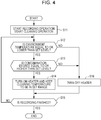
Fig. 4 is a flowchart for explaining control in a second embodiment of the invention. -
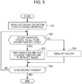
Fig. 5 is a flowchart for explaining control in a third embodiment of the invention. -
Fig. 6 is a schematic side view illustrating main parts in a fourth embodiment of the invention. -
Fig. 7 is a flowchart for explaining control in a fifth embodiment of the invention. -
Fig. 8 is a flowchart for explaining control in a sixth embodiment of the invention. -
Fig. 9 is a flowchart for explaining control in a seventh embodiment of the invention. - Hereinafter, an ink jet recording apparatus as a liquid discharging apparatus according to one embodiment of the invention is described in detail with reference to the accompanying drawings.
-
Fig. 1 is a schematic side view illustrating an ink jet recording apparatus 1 according to a first embodiment of the invention. - The ink jet recording apparatus 1 in the embodiment includes a feeding portion 2. The feeding portion 2 can feed out a roll R1 of a recording medium P formed by a fabric medium in a roll form for recording, as an example. Furthermore, the ink jet recording apparatus 1 includes a transportation mechanism 3. The transportation mechanism 3 transports the recording medium P in a transportation direction A by an
endless transportation belt 10. Thetransportation belt 10 supports the recording medium P on a medium supporting surface F to which an adhesive is attached. It should be noted that the adhesive may not be attached to the transportation belt. In addition, the ink jet recording apparatus 1 includes arecording mechanism 4. Therecording mechanism 4 performs recording by causing a recording head 7 as a discharging head to reciprocate in a width direction (that is also as a width direction of the recording medium P) B of thetransportation belt 10. The width direction B intersects with the transportation direction A of the recording medium P. - The ink jet recording apparatus 1 in the embodiment includes a
cleaning mechanism 15 for cleaning thetransportation belt 10. Furthermore, the ink jet recording apparatus 1 includes a windingmechanism 18. The windingmechanism 18 includes a windingshaft 17 for winding the recording medium P therearound and acutter 16 for cutting the recording medium P that is being wound. - The feeding portion 2 includes a
rotating shaft 5 also serving as a set position of the roll R1 of the recording medium P for recording. The feeding portion 2 has a configuration capable of feeding out the recording medium P to the transportation mechanism 3 from the roll R1 set on therotating shaft 5 through a drivenroller 6. When the recording medium P is fed out to the transportation mechanism 3, therotating shaft 5 rotates in a rotating direction C. - The transportation mechanism 3 includes the
transportation belt 10, atransportation driving roller 8, and a transportation drivenroller 9. Thetransportation belt 10 transports the recording medium P that has been fed out from the feeding portion 2 while supporting the recording medium P. Thetransportation driving roller 8 and the transportation drivenroller 9 move thetransportation belt 10. The recording medium P is mounted on thetransportation belt 10 at a position on the upstream side in the transportation direction A so as to be attached to the medium supporting surface F of thetransportation belt 10 in a pressurized manner by apressure roller 12. - When the recording medium P is transported, the
transportation driving roller 8 rotates in the rotating direction C and thetransportation belt 10 moves in a movement direction E, that is, is rotationally moved. - The
recording mechanism 4 includes the recording head 7, a carriage (not illustrated), and a carriage motor 26 (Fig. 2 ). The recording head 7 discharges ink onto the recording medium P supported by thetransportation belt 10 so as to perform recording. The recording head 7 is mounted on the carriage. Thecarriage motor 26 causes the carriage to reciprocate in the width direction B. It should be noted that inFig. 1 , the width direction B is a perpendicular direction with respect to the plane of the paper on whichFig. 1 is illustrated. - The
recording mechanism 4 causes the recording head 7 to reciprocate for recording at the time of the recording. While the recording head 7 is being moved, the transportation mechanism 3 stops transportation of the recording medium P. In another expression, the reciprocation of the recording head 7 and the transportation of the recording medium P are alternately performed at the time of the recording. That is to say, the transportation mechanism 3 transports the recording medium P intermittently so as to correspond to the reciprocation of the recording head 7 at the time of the recording. - The
recording mechanism 4 has a configuration in which the recording head 7 is caused to reciprocate for recording. Note that the recording mechanism is not limited to having the configuration. Alternatively, the recording mechanism may include a what-is-called line head on which nozzle rows for discharging ink are provided in the width direction intersecting with the transportation direction A. - The
cleaning mechanism 15 of thetransportation belt 10 includes a cleaningroller 13 as a cleaning member, acleaning solution tank 14 accommodating a cleaning agent for cleaning the cleaningroller 13, and acylinder 19 as a pressing portion that presses the cleaningroller 13 against thetransportation belt 10. Thecylinder 19 not only can press the cleaningroller 13 against thetransportation belt 10 but also can separate the cleaningroller 13 from thetransportation belt 10. - The cleaning
roller 13 is pressed against thetransportation belt 10 by thecylinder 19. A controller 20 (seeFig. 2 ) controls the pressing force thereof. - As will be described in detail later, the
controller 20 is electrically connected to thecylinder 19, the feeding portion 2, the transportation mechanism 3, therecording mechanism 4, thecleaning mechanism 15, the windingmechanism 18, and the like and controls to transport the recording medium P intermittently so as to correspond to the reciprocation of the recording head 7. - The cleaning
roller 13 is formed so as to have a length in the width direction B that is longer than the length of thetransportation belt 10 in the width direction B. This enables the cleaningroller 13 to clean overall thetransportation belt 10 in the width direction B. Further, a wide contact surface of thetransportation belt 10 can be cleaned, thereby suppressing cleaning unevenness in thetransportation belt 10 effectively. - The winding
mechanism 18 is a mechanism for winding the recording medium P on which recording has been performed and that has been transported from the transportation mechanism 3 through a drivenroller 11 around the windingshaft 17. That is to say, the windingmechanism 18 winds the recording medium P as a roll R2 by setting a paper tube or the like for winding on the windingshaft 17 and winding the recording medium P around it. - Then, in the ink jet recording apparatus 1 in the embodiment, the
controller 20 controls operations of thecleaning mechanism 15 and the like. That is, thecontroller 20 is configured so as to adjust the pressing force of the cleaningroller 13 by thecylinder 19 based on information relating to the contamination degree of the medium supporting surface F. With this, the strength of the cleaning force of the cleaningroller 13 for the medium supporting surface F can be adjusted effectively and easily. - Instead of the adjustment of the pressing force of the cleaning
roller 13, thecontroller 20 may be configured so as to adjust the rotating speed of the cleaningroller 13 by a cleaningroller motor 37, which will be described later, based on the information relating to the contamination degree of the medium supporting surface F. Alternatively, thecontroller 20 may be configured so as to adjust the transportation speed of thetransportation belt 10 by atransportation motor 27, which will be described later, based on the information relating to the contamination degree of the medium supporting surface F. - Furthermore, a plurality of the adjustment targets may be combined. When the plurality of adjustment targets are combined, they are combined in the following manner. That is, first, the
controller 20 adjusts the pressing force of the cleaningroller 13, and then, adjusts the rotating speed of the cleaningroller 13 when the adjustment is not sufficient. - In the ink jet recording apparatus 1 in the embodiment, a
contamination detector 38 is provided. Thecontamination detector 38 measures the contamination degree of the medium supporting surface F directly. - As the
contamination detector 38, a contamination detector that irradiates the surface of the medium supporting surface F with laser beams so as to obtain the contamination degree based on attenuation of reflected light due to the contamination, and a contamination detector that image-captures the surface of the medium supporting surface F by a charge-coupled device (CCD) camera so as to obtain the contamination degree based on color change can be exemplified. In addition, a contamination detector that emits sound waves onto the surface of - the medium supporting surface F so as to obtain the contamination degree based on change of sound quality such as a frequency and an intensity due to the contamination can be exemplified.
- The information relating to the contamination degree may be defined using physical amounts having correlations with the change of the contamination degree, for example, the number of rotations of the transportation belt and the number of rotations of the motor for driving the transportation belt.
- Alternatively, an image data amount relating to a discharging amount of the liquid, a type of a fabric (whether or not the fabric is a type easy to be permeated with liquid, fiber density and so on) when the medium is a fabric, a method of performing preprocessing on the fabric (permeation processing or non-permeation processing), recording without margins or with margins, whether or not the medium supporting surface is used for a liquid discharging region for flushing, and the like can be used as the information. The flushing is executed as a maintenance operation of the discharging head.
- The ink jet recording apparatus 1 in the embodiment further includes a
heater 40 that supplies heat to a cleaning portion 39 (Fig. 1 ) of the cleaningroller 13 for the medium supporting surface F. Theheater 40 is provided on thecleaning solution tank 14, and is configured so as to heat acleaning solution 41 therein and increase the temperature thereof. As will be described later, a place on which theheater 40 is provided is not limited to thecleaning solution tank 14. Thecontroller 20 is configured to drive theheater 40 through a heater driving portion 43 (Fig. 2 ) so as to control the cleaning temperature on the cleaningportion 39. In addition, in the embodiment, thecontroller 20 is configured to control the cleaning temperature based on information relating to the environment temperature that is obtained by atemperature detector 42. - The expression "cleaning temperature" is a temperature of the cleaning
portion 39 where the cleaningroller 13 cleans by making contact with the medium supporting surface F of thetransportation belt 10 during cleaning. The cleaning temperature is determined by combining temperatures of respective members constituting the cleaningportion 39, such as a temperature of thecleaning solution 41 constituting a part of thecleaning mechanism 15, a temperature of the cleaningroller 13 itself, and a temperature of the medium supporting surface F of thetransportation belt 10. The cleaning temperature is changed by changing the temperature of any one of the members constituting the cleaningportion 39, or the temperatures of equal to or more than two of the members. - Next, an electrical configuration of the ink jet recording apparatus 1 in the embodiment is described with reference to
Fig. 2 . - The
controller 20 is provided with a central processing unit (CPU) 21 for controlling the ink jet recording apparatus 1 overall. TheCPU 21 is connected to a read only memory (ROM) 23 and a random access memory (RAM) 24 through asystem bus 22. TheROM 23 stores therein control programs of various types, which are executed by theCPU 21, and the like. TheRAM 24 can store data temporarily. TheCPU 21 is connected to ahead driving portion 25 for driving the recording head 7 through thesystem bus 22. - The
CPU 21 is connected to amotor driving portion 32 through thesystem bus 22. Themotor driving portion 32 is a portion for driving thecarriage motor 26, thetransportation motor 27, a feedingmotor 28, a windingmotor 29, and the cleaningroller motor 37. - The
carriage motor 26 is a motor for moving the carriage (not illustrated) on which the recording head 7 is mounted. Thetransportation motor 27 is a motor for driving thetransportation driving roller 8. The feedingmotor 28 is a rotating mechanism of therotating shaft 5 and is a motor for driving therotating shaft 5 for feeding out the recording medium P to the transportation mechanism 3. The windingmotor 29 is a driving motor for rotating the windingshaft 17. The cleaningroller motor 37 is a motor for rotating the cleaningroller 13. - The
CPU 21 is connected to acylinder driving portion 36 through thesystem bus 22. TheCPU 21 is also connected to acutter driving portion 33 for driving thecutter 16 to cut the recording medium P through thesystem bus 22. TheCPU 21 is further connected to theheater driving portion 43 for driving theheater 40 through thesystem bus 22. - Further, the
CPU 21 is connected to an input/output portion 30. The input/output portion 30 is connected to amonitor 34, acontrol panel 35, aninterface 31 for inputting recording data and the like from an external apparatus such as a personal computer (PC) and so on, thecontamination detector 38, and thetemperature detector 42 that are provided on the ink jet recording apparatus 1 in order to transmit/receive data and signals to and from them. Description of Action,Fig. 3 - An action of the embodiment is described with reference to
Fig. 3 . - A recording operation is started at step S1. With the recording operation, ink is discharged from the recording head 7 and recording of an image corresponding to image data is executed on the recording medium P that is being transported intermittently in the transportation direction A by the
transportation belt 10 while being supported on the medium supporting surface F. - A cleaning operation is also started at step S1. That is to say, cleaning is performed in a state where the cleaning
roller 13 is pressed against the medium supporting surface F of thetransportation belt 10 with an initially set pressing force by thecylinder 19. - Whether or not the environment temperature obtained by the
temperature detector 42 is equal to or lower than a set level is determined at step S2. The set level can be set appropriately by acquiring test data indicating that cleaning capability by the cleaningroller 13 is lowered due to lowering of the environment temperature. - When the environment temperature is low and the determination at step S2 is "Yes", the process proceeds to step S3 and the
heater 40 is turned ON. With this, the temperature of thecleaning solution 41 is increased, so that the cleaning capability is enhanced. The processing at step S3 is controlled so as to prevent the temperature of the cleaning solution from being increased too high and the temperature of the cleaning solution is kept in a set ra nge. - Subsequently, the process proceeds to step S4, and whether or not recording is finished is determined. When the determination is "No", the process returns to step S2.
- When the determination is "No" at step S2, the process proceeds to step S5. That is, the
heater 40 is turned OFF and unnecessary heating is stopped. Then, the process proceeds to ste p S4. - As is understood by the above description with reference to
Fig. 3 , according to the embodiment, the cleaning temperature on the cleaningportion 39 can be controlled to be increased. With this, even when the environment temperature lowers, the control is performed so as not to be influenced easily by the lowering of the environment temperature. That is to say, lowering of the cleaning capability can be suppressed even when the environment temperature lowers. - Control in a second embodiment is described with reference to
Fig. 4 . - A recording operation is started at step S11. With the recording operation, ink is discharged from the recording head 7 and recording of an image corresponding to image data is executed on the recording medium P that is being transported intermittently in the transportation direction A by the
transportation belt 10 while being supported on the medium supporting surface F. - A cleaning operation is also started at step S11. That is to say, cleaning is performed in a state where the cleaning
roller 13 is pressed against the medium supporting surface F of thetransportation belt 10 with an initially set pressing force by thecylinder 19. - Whether or not the environment temperature obtained by the
temperature detector 42 is equal to or lower than a set level is determined at step S12. When the environment temperature is low and the determination at step S12 is "Yes", the process proceeds to step S13 and whether or not the degree of contamination is equal to or higher than a set level is determined based on the information relating to the contamination degree obtained by thecontamination detector 38. - When the determination is "Yes" in the more highly contaminated state, the process proceeds to step S14 and the
heater 40 is turned ON. With this, the temperature of thecleaning solution 41 is increased, so that the cleaning capability is enhanced. The processing at step S14 is controlled so as to prevent the temperature of the cleaning solution from being increased too high and the temperature of the cleaning solution is kept in a set range. - Subsequently, the process proceeds to step S15, and whether or not recording is finished is determined. When the determination is "No", the process returns to step S12.
- When the determination is "No" at step S12 or step S13, the process proceeds to step S16. That is, the
heater 40 is turned OFF and unnecessary heating is stopped. Then, the process proceeds to step S15. - As is understood by the above description with reference to
Fig. 4 , according to the embodiment, the cleaning temperature on the cleaningportion 39 can be easily controlled to be increased in the highly contaminated state. With this, even when the environment temperature lowers, the control is performed so as not to be influenced easily by the lowering of the environment temperature. That is to say, lowering of the cleaning capability can be suppressed even when the environment temperature lowers. - Control in a third embodiment is described with reference to
Fig. 5 . - A recording operation is started at step S21. With the recording operation, ink is discharged from the recording head 7 and recording of an image corresponding to image data is executed on the recording medium P that is being transported intermittently in the transportation direction A by the
transportation belt 10 while being supported on the medium supporting surface F. - A cleaning operation is also started at step S21. That is to say, cleaning is performed in a state where the cleaning
roller 13 is pressed against the medium supporting surface F of thetransportation belt 10 with an initially set pressing force by thecylinder 19. - Whether or not the degree of contamination is equal to or higher than a set level is determined based on the information relating to the contamination degree obtained by the
contamination detector 38 at step S22. - When the determination is "Yes" in the more highly contaminated state, the process proceeds to step S23 and the
heater 40 is turned ON. With this, the temperature of thecleaning solution 41 is increased, so that the cleaning capability is enhanced. The processing at step S23 is controlled so as to prevent the temperature of the cleaning solution from being increased too high and the temperature of the cleaning solution is kept in a set range. - Subsequently, the process proceeds to step S24, and whether or not recording is finished is determined. When the determination is "No", the process returns to step S22.
- When the determination is "No" at step S22, the process proceeds to step S25. That is, the
heater 40 is turned OFF and unnecessary heating is stopped. Then, the process proceeds to step S24. - As is understood by the above description with reference to
Fig. 5 , according to the embodiment, the cleaning temperature on the cleaningportion 39 can be controlled to be increased. With this, even when the environment temperature lowers, the control is performed so as not to be influenced easily by the lowering of the environment temperature. That is to say, lowering of the cleaning capability can be suppressed even when the environment temperature lowers. - In the above embodiments, the
heater 40 is provided on thecleaning solution tank 14. However, in the present embodiment, abelt heater 45 for supplying heat to thetransportation belt 10 is provided. A cleaning member is constituted by a cleaningbrush 46, a cleaningbrush 47 for cleaning the cleaningbrush 46, andliquid tanks Heaters liquid tanks Fig. 6 , areference numeral 52 denotes a water sprayer and a heater (not illustrated) is also provided on the water sprayer. - As described in the embodiment, the places on which the heaters are provided other than the
cleaning solution tank 14 in the first embodiment can be selected. It is needless to say that the heaters may be provided on only one or some the places as illustrated inFig. 6 . - Control in a fifth embodiment is described with reference to
Fig. 7 . - Processings at step S31 to step S33 and step S35 are the same as the processings at step S1 to step S3 and step S5 in the first embodiment, respectively, and description thereof is omitted.
- Whether or not the degree of contamination on the medium supporting surface F of the
transportation belt 10 is equal to or higher than a set level that has been initially set is determined based on the information relating to the contamination degree measured by thecontamination detector 38 at step S34. When the determination is "Yes", the process proceeds to step S36 and thecylinder 19 is driven to strengthen the pressing force by one stage. With this, the cleaning for thetransportation belt 10 by the cleaningroller 13 is performed with the cleaning force, which has become stronger by one stage. - Subsequently, the process proceeds to step S37, and whether or not recording is finished is determined. When the determination is "No", the process returns to step S32.
- When the determination is "No" at step S34, the process proceeds to step S38 and the
cylinder 19 is driven to weaken the pressing force by one stage. With this, the cleaning for thetransportation belt 10 by the cleaningroller 13 is performed with the cleaning force, which has become weaker by one stage. - As is understood by the above description with reference to
Fig. 7 , according to the embodiment, the cleaning can be performed while adjusting the pressing force of the cleaningroller 13 against the medium supporting surface F to an appropriate pressing force in accordance with the degree of contamination on the medium supporting surface F. This can suppress the abrasion without lowering the cleaning quality on the medium supporting surface F. In steps S36 and S38, if the pressing force has already been increased/decreased to a maximum/minimum force, then that existing pressing force can be maintained instead of being increased/decreased further. - Control in a sixth embodiment is described with reference to
Fig. 8 . - The sixth embodiment is basically the same as the fifth embodiment. The processings at steps S36 and S38 in the fifth embodiment correspond to adjustment (up/down) of the pressing force of the cleaning
roller 13. Instead of this, processings at steps S46 and S48 in the sixth embodiment correspond to adjustment (rotating speed up, rotating speed down) of the rotating speed of the cleaningroller 13. - Description of other configurations and action effects is omitted. Seventh Embodiment,
Fig. 9 - Control in a seventh embodiment is described with reference to
Fig. 9 . - The seventh embodiment is also basically the same as the fifth embodiment. The processings at steps S36 and S38 in the fifth embodiment correspond to adjustment (up/down) of the pressing force of the cleaning
roller 13. Instead of this, processings at steps S56 and S58 in the seventh embodiment correspond to adjustment (extension/shortening) of a stop time (standby time) of thetransportation belt 10 that is moved intermittently, in other words, the time for which thebelt 10 stops at each intermittent movement. - Description of other configurations and action effects is omitted.
- The foregoing description has been given by way of example only and it will be appreciated by a person skilled in the art that modifications can be made without departing from the scope of the present invention.
Claims (8)
- A liquid discharging apparatus (1) comprising:a transportation belt (10) that has a medium supporting surface (F) and is adapted to transport a medium (P) while supporting the medium on the medium supporting surface;a discharging head (7) adapted to discharge liquid onto the medium supported by the transportation belt;a cleaning mechanism (15) that has a cleaning member (13) making contact with the transportation belt so as to clean the medium supporting surface with a cleaning solution;a heater (40) adapted to supply heat to the cleaning solution; anda controller (20) adapted to control a cleaning temperature on a cleaning portion of the medium supporting surface by driving the heater,wherein the controller is adapted to control the cleaning temperature based on information relating to an environment temperature.
- The liquid discharging apparatus according to Claim 1,
wherein the controller is adapted to control the cleaning temperature based on information relating to a contamination degree of the medium supporting surface. - The liquid discharging apparatus according to Claim 1 or Claim 2,
wherein the heater is adapted to supply heat to a cleaning solution tank (14). - The liquid discharging apparatus according to any one of the preceding claims,
wherein the heater is adapted to supply heat to the transportation belt. - The liquid discharging apparatus according to any one of the preceding claims,
wherein the heater is adapted to supply heat to the cleaning member. - The liquid discharging apparatus according to any one of the preceding claims,
wherein the controller is adapted to adjust at least any one of a) a pressing force of the cleaning member (13), b) a rotating speed of the cleaning member (13), and c) a transportation speed of the transportation belt (10) based on the information relating to the contamination degree of the medium supporting surface. - The liquid discharging apparatus according to Claim 6,
wherein the controller (20) is adapted to execute adjustment of a) the pressing force of the cleaning member first based on the information relating to the contamination degree. - The liquid discharging apparatus according to Claim 6 or Claim 7,
wherein the controller has a plurality of cleaning operation modes in which strengths of cleaning forces by the cleaning member for the medium supporting surface are different, and is adapted to select and execute one of the plurality of cleaning operation modes based on the information.
Applications Claiming Priority (2)
| Application Number | Priority Date | Filing Date | Title |
|---|---|---|---|
| JP2013061571A JP2014185010A (en) | 2013-03-25 | 2013-03-25 | Liquid ejection device |
| EP14161090.7A EP2783876B1 (en) | 2013-03-25 | 2014-03-21 | Liquid discharging apparatus |
Related Parent Applications (2)
| Application Number | Title | Priority Date | Filing Date |
|---|---|---|---|
| EP14161090.7A Division EP2783876B1 (en) | 2013-03-25 | 2014-03-21 | Liquid discharging apparatus |
| EP14161090.7A Division-Into EP2783876B1 (en) | 2013-03-25 | 2014-03-21 | Liquid discharging apparatus |
Publications (2)
| Publication Number | Publication Date |
|---|---|
| EP3115218A1 true EP3115218A1 (en) | 2017-01-11 |
| EP3115218B1 EP3115218B1 (en) | 2017-11-22 |
Family
ID=50336210
Family Applications (2)
| Application Number | Title | Priority Date | Filing Date |
|---|---|---|---|
| EP16178948.2A Not-in-force EP3115218B1 (en) | 2013-03-25 | 2014-03-21 | Liquid discharging apparatus |
| EP14161090.7A Active EP2783876B1 (en) | 2013-03-25 | 2014-03-21 | Liquid discharging apparatus |
Family Applications After (1)
| Application Number | Title | Priority Date | Filing Date |
|---|---|---|---|
| EP14161090.7A Active EP2783876B1 (en) | 2013-03-25 | 2014-03-21 | Liquid discharging apparatus |
Country Status (3)
| Country | Link |
|---|---|
| EP (2) | EP3115218B1 (en) |
| JP (1) | JP2014185010A (en) |
| TR (1) | TR201802293T4 (en) |
Cited By (1)
| Publication number | Priority date | Publication date | Assignee | Title |
|---|---|---|---|---|
| US11789386B2 (en) | 2021-08-20 | 2023-10-17 | Seiko Epson Corporation | Recording device and transport device |
Families Citing this family (10)
| Publication number | Priority date | Publication date | Assignee | Title |
|---|---|---|---|---|
| CN108349252B (en) | 2016-01-29 | 2020-04-28 | 惠普发展公司,有限责任合伙企业 | Printing head wiping device |
| JP7298315B2 (en) * | 2019-06-05 | 2023-06-27 | コニカミノルタ株式会社 | image recorder |
| CN111908201B (en) * | 2020-07-15 | 2022-04-19 | 桐乡市嘉灵新材料股份有限公司 | Printing equipment for textile fabric and working method thereof |
| WO2022087884A1 (en) * | 2020-10-28 | 2022-05-05 | 苏州法比瑞纺织科技有限公司 | Easy-to-clean textile fabric printing machine |
| JP7571487B2 (en) * | 2020-11-13 | 2024-10-23 | セイコーエプソン株式会社 | Printing device |
| CN114747987B (en) * | 2021-01-11 | 2023-06-20 | 宁波方太厨具有限公司 | Mop cleanliness self-identification system and base station of cleaning robot |
| CN113429079B (en) * | 2021-07-14 | 2023-01-10 | 江西省华赣环境集团有限公司 | Irrigation water heavy metal removal system |
| JP7722149B2 (en) * | 2021-11-19 | 2025-08-13 | セイコーエプソン株式会社 | Conveying device, liquid ejecting device |
| CN114368635B (en) * | 2022-03-21 | 2022-06-10 | 广东合科泰实业有限公司 | Automatic adjusting device for rail pressing wheel force of sheet arranging machine |
| CN115214242A (en) * | 2022-06-20 | 2022-10-21 | 浙江真爱时尚家居有限公司 | Digital permeation injection device and method for fluff |
Citations (2)
| Publication number | Priority date | Publication date | Assignee | Title |
|---|---|---|---|---|
| JPH11192694A (en) | 1997-12-29 | 1999-07-21 | Canon Inc | Inkjet printing equipment |
| JP2009149019A (en) * | 2007-12-21 | 2009-07-09 | Fujifilm Corp | Image forming apparatus and intermediate transfer member cleaning method |
Family Cites Families (6)
| Publication number | Priority date | Publication date | Assignee | Title |
|---|---|---|---|---|
| US6698878B1 (en) * | 2000-05-30 | 2004-03-02 | Hewlett-Packard Development Company, L.P. | Cleaning medium for ink-jet hard copy apparatus |
| JP4236259B2 (en) * | 2004-03-08 | 2009-03-11 | キヤノン株式会社 | Recording device |
| JP5135092B2 (en) * | 2007-07-27 | 2013-01-30 | 京セラドキュメントソリューションズ株式会社 | Image forming apparatus |
| JP5040576B2 (en) * | 2007-10-15 | 2012-10-03 | セイコーエプソン株式会社 | Detection device and recording device |
| DK2240327T3 (en) * | 2008-02-13 | 2015-04-27 | Xennia Holland B V | The droplet catcher for use in an ink jet printer |
| JP5569366B2 (en) * | 2010-11-30 | 2014-08-13 | コニカミノルタ株式会社 | Belt cleaning device, belt conveying device, and image recording device |
-
2013
- 2013-03-25 JP JP2013061571A patent/JP2014185010A/en active Pending
-
2014
- 2014-03-21 EP EP16178948.2A patent/EP3115218B1/en not_active Not-in-force
- 2014-03-21 TR TR2018/02293T patent/TR201802293T4/en unknown
- 2014-03-21 EP EP14161090.7A patent/EP2783876B1/en active Active
Patent Citations (2)
| Publication number | Priority date | Publication date | Assignee | Title |
|---|---|---|---|---|
| JPH11192694A (en) | 1997-12-29 | 1999-07-21 | Canon Inc | Inkjet printing equipment |
| JP2009149019A (en) * | 2007-12-21 | 2009-07-09 | Fujifilm Corp | Image forming apparatus and intermediate transfer member cleaning method |
Cited By (1)
| Publication number | Priority date | Publication date | Assignee | Title |
|---|---|---|---|---|
| US11789386B2 (en) | 2021-08-20 | 2023-10-17 | Seiko Epson Corporation | Recording device and transport device |
Also Published As
| Publication number | Publication date |
|---|---|
| JP2014185010A (en) | 2014-10-02 |
| EP2783876A1 (en) | 2014-10-01 |
| TR201802293T4 (en) | 2018-03-21 |
| EP3115218B1 (en) | 2017-11-22 |
| EP2783876B1 (en) | 2016-08-17 |
Similar Documents
| Publication | Publication Date | Title |
|---|---|---|
| EP3115218B1 (en) | Liquid discharging apparatus | |
| US8985737B2 (en) | Recording apparatus and recording method | |
| EP3466698A1 (en) | Inkjet recording device | |
| JP6406490B2 (en) | Liquid ejection device | |
| EP3205508B1 (en) | Printing apparatus and method for compressing printing medium | |
| US9186916B1 (en) | Drying device, image forming apparatus, and computer readable medium storing program | |
| CN104070789B (en) | Printing equipment | |
| EP2754557B1 (en) | Recording apparatus and recording method | |
| US10207504B2 (en) | Printing apparatus and printing method | |
| US10328714B2 (en) | Printing apparatus and printing method | |
| US8807683B2 (en) | Liquid discharge method for resolving clogged nozzle arrays | |
| WO2016190335A1 (en) | Inkjet recording device | |
| JP2017024206A (en) | Printer | |
| JP2016221752A (en) | Liquid discharge device | |
| JP2016159581A (en) | Image recording device and image quality defect detecting method | |
| EP3109053B1 (en) | Liquid discharging apparatus | |
| JP6658546B2 (en) | Ink jet recording device | |
| JP6759727B2 (en) | Printing equipment, programs | |
| JP2022082027A (en) | Printing equipment and printing method | |
| JP6589319B2 (en) | Recording device | |
| US12103316B2 (en) | Image forming apparatus, lifetime determination method and non-transitory computer-readable recording medium storing lifetime determination program | |
| JP2020069705A (en) | Recording apparatus and recording method | |
| JP2010137511A (en) | Recording apparatus and recording method | |
| JP2025019493A (en) | Recording device and conveying device | |
| JP2024008166A (en) | Image forming apparatus, method for estimating state change of phase change ink, and program for estimating state change of phase change ink |
Legal Events
| Date | Code | Title | Description |
|---|---|---|---|
| PUAI | Public reference made under article 153(3) epc to a published international application that has entered the european phase |
Free format text: ORIGINAL CODE: 0009012 |
|
| AC | Divisional application: reference to earlier application |
Ref document number: 2783876 Country of ref document: EP Kind code of ref document: P |
|
| AK | Designated contracting states |
Kind code of ref document: A1 Designated state(s): AL AT BE BG CH CY CZ DE DK EE ES FI FR GB GR HR HU IE IS IT LI LT LU LV MC MK MT NL NO PL PT RO RS SE SI SK SM TR |
|
| REG | Reference to a national code |
Ref country code: DE Ref legal event code: R079 Ref document number: 602014017765 Country of ref document: DE Free format text: PREVIOUS MAIN CLASS: B41J0015040000 Ipc: B41J0011000000 |
|
| 17P | Request for examination filed |
Effective date: 20170426 |
|
| RBV | Designated contracting states (corrected) |
Designated state(s): AL AT BE BG CH CY CZ DE DK EE ES FI FR GB GR HR HU IE IS IT LI LT LU LV MC MK MT NL NO PL PT RO RS SE SI SK SM TR |
|
| RIC1 | Information provided on ipc code assigned before grant |
Ipc: B41J 11/00 20060101AFI20170517BHEP Ipc: B41J 29/17 20060101ALI20170517BHEP Ipc: B41J 15/04 20060101ALI20170517BHEP Ipc: B41J 3/407 20060101ALI20170517BHEP Ipc: B65H 20/06 20060101ALI20170517BHEP |
|
| GRAP | Despatch of communication of intention to grant a patent |
Free format text: ORIGINAL CODE: EPIDOSNIGR1 |
|
| INTG | Intention to grant announced |
Effective date: 20170629 |
|
| GRAS | Grant fee paid |
Free format text: ORIGINAL CODE: EPIDOSNIGR3 |
|
| GRAA | (expected) grant |
Free format text: ORIGINAL CODE: 0009210 |
|
| AC | Divisional application: reference to earlier application |
Ref document number: 2783876 Country of ref document: EP Kind code of ref document: P |
|
| AK | Designated contracting states |
Kind code of ref document: B1 Designated state(s): AL AT BE BG CH CY CZ DE DK EE ES FI FR GB GR HR HU IE IS IT LI LT LU LV MC MK MT NL NO PL PT RO RS SE SI SK SM TR |
|
| REG | Reference to a national code |
Ref country code: GB Ref legal event code: FG4D |
|
| REG | Reference to a national code |
Ref country code: CH Ref legal event code: EP |
|
| REG | Reference to a national code |
Ref country code: IE Ref legal event code: FG4D |
|
| REG | Reference to a national code |
Ref country code: AT Ref legal event code: REF Ref document number: 948035 Country of ref document: AT Kind code of ref document: T Effective date: 20171215 |
|
| REG | Reference to a national code |
Ref country code: DE Ref legal event code: R096 Ref document number: 602014017765 Country of ref document: DE |
|
| REG | Reference to a national code |
Ref country code: FR Ref legal event code: PLFP Year of fee payment: 5 |
|
| REG | Reference to a national code |
Ref country code: NL Ref legal event code: MP Effective date: 20171122 |
|
| REG | Reference to a national code |
Ref country code: LT Ref legal event code: MG4D |
|
| REG | Reference to a national code |
Ref country code: AT Ref legal event code: MK05 Ref document number: 948035 Country of ref document: AT Kind code of ref document: T Effective date: 20171122 |
|
| PG25 | Lapsed in a contracting state [announced via postgrant information from national office to epo] |
Ref country code: ES Free format text: LAPSE BECAUSE OF FAILURE TO SUBMIT A TRANSLATION OF THE DESCRIPTION OR TO PAY THE FEE WITHIN THE PRESCRIBED TIME-LIMIT Effective date: 20171122 Ref country code: LT Free format text: LAPSE BECAUSE OF FAILURE TO SUBMIT A TRANSLATION OF THE DESCRIPTION OR TO PAY THE FEE WITHIN THE PRESCRIBED TIME-LIMIT Effective date: 20171122 Ref country code: SE Free format text: LAPSE BECAUSE OF FAILURE TO SUBMIT A TRANSLATION OF THE DESCRIPTION OR TO PAY THE FEE WITHIN THE PRESCRIBED TIME-LIMIT Effective date: 20171122 Ref country code: FI Free format text: LAPSE BECAUSE OF FAILURE TO SUBMIT A TRANSLATION OF THE DESCRIPTION OR TO PAY THE FEE WITHIN THE PRESCRIBED TIME-LIMIT Effective date: 20171122 Ref country code: NO Free format text: LAPSE BECAUSE OF FAILURE TO SUBMIT A TRANSLATION OF THE DESCRIPTION OR TO PAY THE FEE WITHIN THE PRESCRIBED TIME-LIMIT Effective date: 20180222 Ref country code: NL Free format text: LAPSE BECAUSE OF FAILURE TO SUBMIT A TRANSLATION OF THE DESCRIPTION OR TO PAY THE FEE WITHIN THE PRESCRIBED TIME-LIMIT Effective date: 20171122 |
|
| PG25 | Lapsed in a contracting state [announced via postgrant information from national office to epo] |
Ref country code: LV Free format text: LAPSE BECAUSE OF FAILURE TO SUBMIT A TRANSLATION OF THE DESCRIPTION OR TO PAY THE FEE WITHIN THE PRESCRIBED TIME-LIMIT Effective date: 20171122 Ref country code: BG Free format text: LAPSE BECAUSE OF FAILURE TO SUBMIT A TRANSLATION OF THE DESCRIPTION OR TO PAY THE FEE WITHIN THE PRESCRIBED TIME-LIMIT Effective date: 20180222 Ref country code: HR Free format text: LAPSE BECAUSE OF FAILURE TO SUBMIT A TRANSLATION OF THE DESCRIPTION OR TO PAY THE FEE WITHIN THE PRESCRIBED TIME-LIMIT Effective date: 20171122 Ref country code: GR Free format text: LAPSE BECAUSE OF FAILURE TO SUBMIT A TRANSLATION OF THE DESCRIPTION OR TO PAY THE FEE WITHIN THE PRESCRIBED TIME-LIMIT Effective date: 20180223 Ref country code: RS Free format text: LAPSE BECAUSE OF FAILURE TO SUBMIT A TRANSLATION OF THE DESCRIPTION OR TO PAY THE FEE WITHIN THE PRESCRIBED TIME-LIMIT Effective date: 20171122 Ref country code: AT Free format text: LAPSE BECAUSE OF FAILURE TO SUBMIT A TRANSLATION OF THE DESCRIPTION OR TO PAY THE FEE WITHIN THE PRESCRIBED TIME-LIMIT Effective date: 20171122 |
|
| PG25 | Lapsed in a contracting state [announced via postgrant information from national office to epo] |
Ref country code: SK Free format text: LAPSE BECAUSE OF FAILURE TO SUBMIT A TRANSLATION OF THE DESCRIPTION OR TO PAY THE FEE WITHIN THE PRESCRIBED TIME-LIMIT Effective date: 20171122 Ref country code: CZ Free format text: LAPSE BECAUSE OF FAILURE TO SUBMIT A TRANSLATION OF THE DESCRIPTION OR TO PAY THE FEE WITHIN THE PRESCRIBED TIME-LIMIT Effective date: 20171122 Ref country code: CY Free format text: LAPSE BECAUSE OF FAILURE TO SUBMIT A TRANSLATION OF THE DESCRIPTION OR TO PAY THE FEE WITHIN THE PRESCRIBED TIME-LIMIT Effective date: 20171122 Ref country code: EE Free format text: LAPSE BECAUSE OF FAILURE TO SUBMIT A TRANSLATION OF THE DESCRIPTION OR TO PAY THE FEE WITHIN THE PRESCRIBED TIME-LIMIT Effective date: 20171122 Ref country code: DK Free format text: LAPSE BECAUSE OF FAILURE TO SUBMIT A TRANSLATION OF THE DESCRIPTION OR TO PAY THE FEE WITHIN THE PRESCRIBED TIME-LIMIT Effective date: 20171122 |
|
| REG | Reference to a national code |
Ref country code: DE Ref legal event code: R097 Ref document number: 602014017765 Country of ref document: DE |
|
| PG25 | Lapsed in a contracting state [announced via postgrant information from national office to epo] |
Ref country code: SM Free format text: LAPSE BECAUSE OF FAILURE TO SUBMIT A TRANSLATION OF THE DESCRIPTION OR TO PAY THE FEE WITHIN THE PRESCRIBED TIME-LIMIT Effective date: 20171122 Ref country code: RO Free format text: LAPSE BECAUSE OF FAILURE TO SUBMIT A TRANSLATION OF THE DESCRIPTION OR TO PAY THE FEE WITHIN THE PRESCRIBED TIME-LIMIT Effective date: 20171122 Ref country code: PL Free format text: LAPSE BECAUSE OF FAILURE TO SUBMIT A TRANSLATION OF THE DESCRIPTION OR TO PAY THE FEE WITHIN THE PRESCRIBED TIME-LIMIT Effective date: 20171122 |
|
| PLBE | No opposition filed within time limit |
Free format text: ORIGINAL CODE: 0009261 |
|
| STAA | Information on the status of an ep patent application or granted ep patent |
Free format text: STATUS: NO OPPOSITION FILED WITHIN TIME LIMIT |
|
| 26N | No opposition filed |
Effective date: 20180823 |
|
| REG | Reference to a national code |
Ref country code: CH Ref legal event code: PL |
|
| GBPC | Gb: european patent ceased through non-payment of renewal fee |
Effective date: 20180321 |
|
| PG25 | Lapsed in a contracting state [announced via postgrant information from national office to epo] |
Ref country code: MC Free format text: LAPSE BECAUSE OF FAILURE TO SUBMIT A TRANSLATION OF THE DESCRIPTION OR TO PAY THE FEE WITHIN THE PRESCRIBED TIME-LIMIT Effective date: 20171122 |
|
| REG | Reference to a national code |
Ref country code: BE Ref legal event code: MM Effective date: 20180331 |
|
| REG | Reference to a national code |
Ref country code: IE Ref legal event code: MM4A |
|
| PG25 | Lapsed in a contracting state [announced via postgrant information from national office to epo] |
Ref country code: LU Free format text: LAPSE BECAUSE OF NON-PAYMENT OF DUE FEES Effective date: 20180321 |
|
| PG25 | Lapsed in a contracting state [announced via postgrant information from national office to epo] |
Ref country code: IE Free format text: LAPSE BECAUSE OF NON-PAYMENT OF DUE FEES Effective date: 20180321 |
|
| PG25 | Lapsed in a contracting state [announced via postgrant information from national office to epo] |
Ref country code: BE Free format text: LAPSE BECAUSE OF NON-PAYMENT OF DUE FEES Effective date: 20180331 Ref country code: GB Free format text: LAPSE BECAUSE OF NON-PAYMENT OF DUE FEES Effective date: 20180321 Ref country code: LI Free format text: LAPSE BECAUSE OF NON-PAYMENT OF DUE FEES Effective date: 20180331 Ref country code: CH Free format text: LAPSE BECAUSE OF NON-PAYMENT OF DUE FEES Effective date: 20180331 |
|
| PG25 | Lapsed in a contracting state [announced via postgrant information from national office to epo] |
Ref country code: MT Free format text: LAPSE BECAUSE OF NON-PAYMENT OF DUE FEES Effective date: 20180321 |
|
| PG25 | Lapsed in a contracting state [announced via postgrant information from national office to epo] |
Ref country code: PT Free format text: LAPSE BECAUSE OF FAILURE TO SUBMIT A TRANSLATION OF THE DESCRIPTION OR TO PAY THE FEE WITHIN THE PRESCRIBED TIME-LIMIT Effective date: 20171122 |
|
| PG25 | Lapsed in a contracting state [announced via postgrant information from national office to epo] |
Ref country code: HU Free format text: LAPSE BECAUSE OF FAILURE TO SUBMIT A TRANSLATION OF THE DESCRIPTION OR TO PAY THE FEE WITHIN THE PRESCRIBED TIME-LIMIT; INVALID AB INITIO Effective date: 20140321 Ref country code: MK Free format text: LAPSE BECAUSE OF NON-PAYMENT OF DUE FEES Effective date: 20171122 |
|
| PG25 | Lapsed in a contracting state [announced via postgrant information from national office to epo] |
Ref country code: AL Free format text: LAPSE BECAUSE OF FAILURE TO SUBMIT A TRANSLATION OF THE DESCRIPTION OR TO PAY THE FEE WITHIN THE PRESCRIBED TIME-LIMIT Effective date: 20171122 Ref country code: IS Free format text: LAPSE BECAUSE OF FAILURE TO SUBMIT A TRANSLATION OF THE DESCRIPTION OR TO PAY THE FEE WITHIN THE PRESCRIBED TIME-LIMIT Effective date: 20180322 |
|
| PG25 | Lapsed in a contracting state [announced via postgrant information from national office to epo] |
Ref country code: SI Free format text: LAPSE BECAUSE OF NON-PAYMENT OF DUE FEES Effective date: 20180321 |
|
| PGFP | Annual fee paid to national office [announced via postgrant information from national office to epo] |
Ref country code: FR Payment date: 20210210 Year of fee payment: 8 Ref country code: IT Payment date: 20210211 Year of fee payment: 8 |
|
| PGFP | Annual fee paid to national office [announced via postgrant information from national office to epo] |
Ref country code: DE Payment date: 20210310 Year of fee payment: 8 Ref country code: TR Payment date: 20210318 Year of fee payment: 8 |
|
| REG | Reference to a national code |
Ref country code: DE Ref legal event code: R119 Ref document number: 602014017765 Country of ref document: DE |
|
| PG25 | Lapsed in a contracting state [announced via postgrant information from national office to epo] |
Ref country code: FR Free format text: LAPSE BECAUSE OF NON-PAYMENT OF DUE FEES Effective date: 20220331 Ref country code: DE Free format text: LAPSE BECAUSE OF NON-PAYMENT OF DUE FEES Effective date: 20221001 |
|
| PG25 | Lapsed in a contracting state [announced via postgrant information from national office to epo] |
Ref country code: IT Free format text: LAPSE BECAUSE OF NON-PAYMENT OF DUE FEES Effective date: 20220321 |
|
| PG25 | Lapsed in a contracting state [announced via postgrant information from national office to epo] |
Ref country code: TR Free format text: LAPSE BECAUSE OF NON-PAYMENT OF DUE FEES Effective date: 20220321 |