EP3115147A1 - Systems and methods for turbine blade repair - Google Patents
Systems and methods for turbine blade repair Download PDFInfo
- Publication number
- EP3115147A1 EP3115147A1 EP16177837.8A EP16177837A EP3115147A1 EP 3115147 A1 EP3115147 A1 EP 3115147A1 EP 16177837 A EP16177837 A EP 16177837A EP 3115147 A1 EP3115147 A1 EP 3115147A1
- Authority
- EP
- European Patent Office
- Prior art keywords
- squealer tip
- turbine blade
- extension
- sintering
- replacement
- Prior art date
- Legal status (The legal status is an assumption and is not a legal conclusion. Google has not performed a legal analysis and makes no representation as to the accuracy of the status listed.)
- Pending
Links
Images


Classifications
-
- F—MECHANICAL ENGINEERING; LIGHTING; HEATING; WEAPONS; BLASTING
- F01—MACHINES OR ENGINES IN GENERAL; ENGINE PLANTS IN GENERAL; STEAM ENGINES
- F01D—NON-POSITIVE DISPLACEMENT MACHINES OR ENGINES, e.g. STEAM TURBINES
- F01D5/00—Blades; Blade-carrying members; Heating, heat-insulating, cooling or antivibration means on the blades or the members
- F01D5/12—Blades
- F01D5/14—Form or construction
- F01D5/18—Hollow blades, i.e. blades with cooling or heating channels or cavities; Heating, heat-insulating or cooling means on blades
- F01D5/181—Blades having a closed internal cavity containing a cooling medium, e.g. sodium
-
- F—MECHANICAL ENGINEERING; LIGHTING; HEATING; WEAPONS; BLASTING
- F01—MACHINES OR ENGINES IN GENERAL; ENGINE PLANTS IN GENERAL; STEAM ENGINES
- F01D—NON-POSITIVE DISPLACEMENT MACHINES OR ENGINES, e.g. STEAM TURBINES
- F01D5/00—Blades; Blade-carrying members; Heating, heat-insulating, cooling or antivibration means on the blades or the members
- F01D5/005—Repairing methods or devices
-
- B—PERFORMING OPERATIONS; TRANSPORTING
- B22—CASTING; POWDER METALLURGY
- B22F—WORKING METALLIC POWDER; MANUFACTURE OF ARTICLES FROM METALLIC POWDER; MAKING METALLIC POWDER; APPARATUS OR DEVICES SPECIALLY ADAPTED FOR METALLIC POWDER
- B22F10/00—Additive manufacturing of workpieces or articles from metallic powder
-
- B—PERFORMING OPERATIONS; TRANSPORTING
- B22—CASTING; POWDER METALLURGY
- B22F—WORKING METALLIC POWDER; MANUFACTURE OF ARTICLES FROM METALLIC POWDER; MAKING METALLIC POWDER; APPARATUS OR DEVICES SPECIALLY ADAPTED FOR METALLIC POWDER
- B22F10/00—Additive manufacturing of workpieces or articles from metallic powder
- B22F10/20—Direct sintering or melting
- B22F10/28—Powder bed fusion, e.g. selective laser melting [SLM] or electron beam melting [EBM]
-
- B—PERFORMING OPERATIONS; TRANSPORTING
- B22—CASTING; POWDER METALLURGY
- B22F—WORKING METALLIC POWDER; MANUFACTURE OF ARTICLES FROM METALLIC POWDER; MAKING METALLIC POWDER; APPARATUS OR DEVICES SPECIALLY ADAPTED FOR METALLIC POWDER
- B22F5/00—Manufacture of workpieces or articles from metallic powder characterised by the special shape of the product
- B22F5/04—Manufacture of workpieces or articles from metallic powder characterised by the special shape of the product of turbine blades
-
- B—PERFORMING OPERATIONS; TRANSPORTING
- B22—CASTING; POWDER METALLURGY
- B22F—WORKING METALLIC POWDER; MANUFACTURE OF ARTICLES FROM METALLIC POWDER; MAKING METALLIC POWDER; APPARATUS OR DEVICES SPECIALLY ADAPTED FOR METALLIC POWDER
- B22F7/00—Manufacture of composite layers, workpieces, or articles, comprising metallic powder, by sintering the powder, with or without compacting wherein at least one part is obtained by sintering or compression
- B22F7/06—Manufacture of composite layers, workpieces, or articles, comprising metallic powder, by sintering the powder, with or without compacting wherein at least one part is obtained by sintering or compression of composite workpieces or articles from parts, e.g. to form tipped tools
- B22F7/062—Manufacture of composite layers, workpieces, or articles, comprising metallic powder, by sintering the powder, with or without compacting wherein at least one part is obtained by sintering or compression of composite workpieces or articles from parts, e.g. to form tipped tools involving the connection or repairing of preformed parts
-
- B—PERFORMING OPERATIONS; TRANSPORTING
- B23—MACHINE TOOLS; METAL-WORKING NOT OTHERWISE PROVIDED FOR
- B23K—SOLDERING OR UNSOLDERING; WELDING; CLADDING OR PLATING BY SOLDERING OR WELDING; CUTTING BY APPLYING HEAT LOCALLY, e.g. FLAME CUTTING; WORKING BY LASER BEAM
- B23K26/00—Working by laser beam, e.g. welding, cutting or boring
- B23K26/34—Laser welding for purposes other than joining
- B23K26/342—Build-up welding
-
- B—PERFORMING OPERATIONS; TRANSPORTING
- B23—MACHINE TOOLS; METAL-WORKING NOT OTHERWISE PROVIDED FOR
- B23P—METAL-WORKING NOT OTHERWISE PROVIDED FOR; COMBINED OPERATIONS; UNIVERSAL MACHINE TOOLS
- B23P6/00—Restoring or reconditioning objects
- B23P6/002—Repairing turbine components, e.g. moving or stationary blades, rotors
- B23P6/007—Repairing turbine components, e.g. moving or stationary blades, rotors using only additive methods, e.g. build-up welding
-
- B—PERFORMING OPERATIONS; TRANSPORTING
- B33—ADDITIVE MANUFACTURING TECHNOLOGY
- B33Y—ADDITIVE MANUFACTURING, i.e. MANUFACTURING OF THREE-DIMENSIONAL [3D] OBJECTS BY ADDITIVE DEPOSITION, ADDITIVE AGGLOMERATION OR ADDITIVE LAYERING, e.g. BY 3D PRINTING, STEREOLITHOGRAPHY OR SELECTIVE LASER SINTERING
- B33Y10/00—Processes of additive manufacturing
-
- B—PERFORMING OPERATIONS; TRANSPORTING
- B33—ADDITIVE MANUFACTURING TECHNOLOGY
- B33Y—ADDITIVE MANUFACTURING, i.e. MANUFACTURING OF THREE-DIMENSIONAL [3D] OBJECTS BY ADDITIVE DEPOSITION, ADDITIVE AGGLOMERATION OR ADDITIVE LAYERING, e.g. BY 3D PRINTING, STEREOLITHOGRAPHY OR SELECTIVE LASER SINTERING
- B33Y80/00—Products made by additive manufacturing
-
- F—MECHANICAL ENGINEERING; LIGHTING; HEATING; WEAPONS; BLASTING
- F01—MACHINES OR ENGINES IN GENERAL; ENGINE PLANTS IN GENERAL; STEAM ENGINES
- F01D—NON-POSITIVE DISPLACEMENT MACHINES OR ENGINES, e.g. STEAM TURBINES
- F01D5/00—Blades; Blade-carrying members; Heating, heat-insulating, cooling or antivibration means on the blades or the members
- F01D5/12—Blades
- F01D5/14—Form or construction
-
- F—MECHANICAL ENGINEERING; LIGHTING; HEATING; WEAPONS; BLASTING
- F01—MACHINES OR ENGINES IN GENERAL; ENGINE PLANTS IN GENERAL; STEAM ENGINES
- F01D—NON-POSITIVE DISPLACEMENT MACHINES OR ENGINES, e.g. STEAM TURBINES
- F01D5/00—Blades; Blade-carrying members; Heating, heat-insulating, cooling or antivibration means on the blades or the members
- F01D5/12—Blades
- F01D5/14—Form or construction
- F01D5/18—Hollow blades, i.e. blades with cooling or heating channels or cavities; Heating, heat-insulating or cooling means on blades
- F01D5/187—Convection cooling
-
- F—MECHANICAL ENGINEERING; LIGHTING; HEATING; WEAPONS; BLASTING
- F01—MACHINES OR ENGINES IN GENERAL; ENGINE PLANTS IN GENERAL; STEAM ENGINES
- F01D—NON-POSITIVE DISPLACEMENT MACHINES OR ENGINES, e.g. STEAM TURBINES
- F01D5/00—Blades; Blade-carrying members; Heating, heat-insulating, cooling or antivibration means on the blades or the members
- F01D5/12—Blades
- F01D5/14—Form or construction
- F01D5/20—Specially-shaped blade tips to seal space between tips and stator
-
- F—MECHANICAL ENGINEERING; LIGHTING; HEATING; WEAPONS; BLASTING
- F01—MACHINES OR ENGINES IN GENERAL; ENGINE PLANTS IN GENERAL; STEAM ENGINES
- F01D—NON-POSITIVE DISPLACEMENT MACHINES OR ENGINES, e.g. STEAM TURBINES
- F01D5/00—Blades; Blade-carrying members; Heating, heat-insulating, cooling or antivibration means on the blades or the members
- F01D5/12—Blades
- F01D5/28—Selecting particular materials; Particular measures relating thereto; Measures against erosion or corrosion
-
- B—PERFORMING OPERATIONS; TRANSPORTING
- B22—CASTING; POWDER METALLURGY
- B22F—WORKING METALLIC POWDER; MANUFACTURE OF ARTICLES FROM METALLIC POWDER; MAKING METALLIC POWDER; APPARATUS OR DEVICES SPECIALLY ADAPTED FOR METALLIC POWDER
- B22F7/00—Manufacture of composite layers, workpieces, or articles, comprising metallic powder, by sintering the powder, with or without compacting wherein at least one part is obtained by sintering or compression
- B22F7/06—Manufacture of composite layers, workpieces, or articles, comprising metallic powder, by sintering the powder, with or without compacting wherein at least one part is obtained by sintering or compression of composite workpieces or articles from parts, e.g. to form tipped tools
- B22F7/062—Manufacture of composite layers, workpieces, or articles, comprising metallic powder, by sintering the powder, with or without compacting wherein at least one part is obtained by sintering or compression of composite workpieces or articles from parts, e.g. to form tipped tools involving the connection or repairing of preformed parts
- B22F2007/068—Manufacture of composite layers, workpieces, or articles, comprising metallic powder, by sintering the powder, with or without compacting wherein at least one part is obtained by sintering or compression of composite workpieces or articles from parts, e.g. to form tipped tools involving the connection or repairing of preformed parts repairing articles
-
- B—PERFORMING OPERATIONS; TRANSPORTING
- B23—MACHINE TOOLS; METAL-WORKING NOT OTHERWISE PROVIDED FOR
- B23K—SOLDERING OR UNSOLDERING; WELDING; CLADDING OR PLATING BY SOLDERING OR WELDING; CUTTING BY APPLYING HEAT LOCALLY, e.g. FLAME CUTTING; WORKING BY LASER BEAM
- B23K2101/00—Articles made by soldering, welding or cutting
- B23K2101/001—Turbines
-
- F—MECHANICAL ENGINEERING; LIGHTING; HEATING; WEAPONS; BLASTING
- F05—INDEXING SCHEMES RELATING TO ENGINES OR PUMPS IN VARIOUS SUBCLASSES OF CLASSES F01-F04
- F05D—INDEXING SCHEME FOR ASPECTS RELATING TO NON-POSITIVE-DISPLACEMENT MACHINES OR ENGINES, GAS-TURBINES OR JET-PROPULSION PLANTS
- F05D2220/00—Application
- F05D2220/30—Application in turbines
- F05D2220/32—Application in turbines in gas turbines
-
- F—MECHANICAL ENGINEERING; LIGHTING; HEATING; WEAPONS; BLASTING
- F05—INDEXING SCHEMES RELATING TO ENGINES OR PUMPS IN VARIOUS SUBCLASSES OF CLASSES F01-F04
- F05D—INDEXING SCHEME FOR ASPECTS RELATING TO NON-POSITIVE-DISPLACEMENT MACHINES OR ENGINES, GAS-TURBINES OR JET-PROPULSION PLANTS
- F05D2230/00—Manufacture
- F05D2230/10—Manufacture by removing material
-
- F—MECHANICAL ENGINEERING; LIGHTING; HEATING; WEAPONS; BLASTING
- F05—INDEXING SCHEMES RELATING TO ENGINES OR PUMPS IN VARIOUS SUBCLASSES OF CLASSES F01-F04
- F05D—INDEXING SCHEME FOR ASPECTS RELATING TO NON-POSITIVE-DISPLACEMENT MACHINES OR ENGINES, GAS-TURBINES OR JET-PROPULSION PLANTS
- F05D2230/00—Manufacture
- F05D2230/10—Manufacture by removing material
- F05D2230/13—Manufacture by removing material using lasers
-
- F—MECHANICAL ENGINEERING; LIGHTING; HEATING; WEAPONS; BLASTING
- F05—INDEXING SCHEMES RELATING TO ENGINES OR PUMPS IN VARIOUS SUBCLASSES OF CLASSES F01-F04
- F05D—INDEXING SCHEME FOR ASPECTS RELATING TO NON-POSITIVE-DISPLACEMENT MACHINES OR ENGINES, GAS-TURBINES OR JET-PROPULSION PLANTS
- F05D2230/00—Manufacture
- F05D2230/20—Manufacture essentially without removing material
- F05D2230/22—Manufacture essentially without removing material by sintering
-
- F—MECHANICAL ENGINEERING; LIGHTING; HEATING; WEAPONS; BLASTING
- F05—INDEXING SCHEMES RELATING TO ENGINES OR PUMPS IN VARIOUS SUBCLASSES OF CLASSES F01-F04
- F05D—INDEXING SCHEME FOR ASPECTS RELATING TO NON-POSITIVE-DISPLACEMENT MACHINES OR ENGINES, GAS-TURBINES OR JET-PROPULSION PLANTS
- F05D2230/00—Manufacture
- F05D2230/20—Manufacture essentially without removing material
- F05D2230/23—Manufacture essentially without removing material by permanently joining parts together
- F05D2230/232—Manufacture essentially without removing material by permanently joining parts together by welding
- F05D2230/234—Laser welding
-
- F—MECHANICAL ENGINEERING; LIGHTING; HEATING; WEAPONS; BLASTING
- F05—INDEXING SCHEMES RELATING TO ENGINES OR PUMPS IN VARIOUS SUBCLASSES OF CLASSES F01-F04
- F05D—INDEXING SCHEME FOR ASPECTS RELATING TO NON-POSITIVE-DISPLACEMENT MACHINES OR ENGINES, GAS-TURBINES OR JET-PROPULSION PLANTS
- F05D2230/00—Manufacture
- F05D2230/80—Repairing, retrofitting or upgrading methods
-
- F—MECHANICAL ENGINEERING; LIGHTING; HEATING; WEAPONS; BLASTING
- F05—INDEXING SCHEMES RELATING TO ENGINES OR PUMPS IN VARIOUS SUBCLASSES OF CLASSES F01-F04
- F05D—INDEXING SCHEME FOR ASPECTS RELATING TO NON-POSITIVE-DISPLACEMENT MACHINES OR ENGINES, GAS-TURBINES OR JET-PROPULSION PLANTS
- F05D2240/00—Components
- F05D2240/20—Rotors
- F05D2240/30—Characteristics of rotor blades, i.e. of any element transforming dynamic fluid energy to or from rotational energy and being attached to a rotor
- F05D2240/307—Characteristics of rotor blades, i.e. of any element transforming dynamic fluid energy to or from rotational energy and being attached to a rotor related to the tip of a rotor blade
-
- F—MECHANICAL ENGINEERING; LIGHTING; HEATING; WEAPONS; BLASTING
- F05—INDEXING SCHEMES RELATING TO ENGINES OR PUMPS IN VARIOUS SUBCLASSES OF CLASSES F01-F04
- F05D—INDEXING SCHEME FOR ASPECTS RELATING TO NON-POSITIVE-DISPLACEMENT MACHINES OR ENGINES, GAS-TURBINES OR JET-PROPULSION PLANTS
- F05D2300/00—Materials; Properties thereof
- F05D2300/10—Metals, alloys or intermetallic compounds
- F05D2300/17—Alloys
- F05D2300/173—Aluminium alloys, e.g. AlCuMgPb
-
- F—MECHANICAL ENGINEERING; LIGHTING; HEATING; WEAPONS; BLASTING
- F05—INDEXING SCHEMES RELATING TO ENGINES OR PUMPS IN VARIOUS SUBCLASSES OF CLASSES F01-F04
- F05D—INDEXING SCHEME FOR ASPECTS RELATING TO NON-POSITIVE-DISPLACEMENT MACHINES OR ENGINES, GAS-TURBINES OR JET-PROPULSION PLANTS
- F05D2300/00—Materials; Properties thereof
- F05D2300/10—Metals, alloys or intermetallic compounds
- F05D2300/17—Alloys
- F05D2300/175—Superalloys
-
- Y—GENERAL TAGGING OF NEW TECHNOLOGICAL DEVELOPMENTS; GENERAL TAGGING OF CROSS-SECTIONAL TECHNOLOGIES SPANNING OVER SEVERAL SECTIONS OF THE IPC; TECHNICAL SUBJECTS COVERED BY FORMER USPC CROSS-REFERENCE ART COLLECTIONS [XRACs] AND DIGESTS
- Y02—TECHNOLOGIES OR APPLICATIONS FOR MITIGATION OR ADAPTATION AGAINST CLIMATE CHANGE
- Y02P—CLIMATE CHANGE MITIGATION TECHNOLOGIES IN THE PRODUCTION OR PROCESSING OF GOODS
- Y02P10/00—Technologies related to metal processing
- Y02P10/25—Process efficiency
Definitions
- the present application and the resultant patent relate generally to gas turbine engines and more particularly relate to systems and methods for three-dimensional turbine airfoil squealer tip repair with improved internal cooling geometry for an extended component lifetime.
- Cast turbine blades often include a structure known as a "squealer tip".
- a squealer tip is a relatively small extension of the blade.
- the squealer tip may have a cross-sectional shape conforming to that of the blade and may be integral with or mounted on the radially outer end of the blade. After a period of time in service, the squealer tip may be eroded, oxidized, and/or corroded by impingement of the hot combustion gases. Because the turbine blade may be expensive to produce, repair or refurbishment of the damaged blade may be preferred if possible.
- the repair of a turbine blade squealer tip may be performed by grinding away the damaged material and then welding or otherwise attaching replacement material. Cooling the squealer tip also may extend the overall useful component lifetime. Providing cooling, however, has been difficult due to manufacturing constraints.
- the present application and the resulting patent provide a method of repairing a turbine blade.
- the method may include the steps of removing an existing squealer tip from the turbine blade in whole or in part, positioning the turbine blade in an additive manufacturing system, and building up an extension of a replacement squealer tip on the turbine blade in whole or in part. Building up an extension of a replacement squealer tip may include creating a cooling passage or a number of cooling passages through the extension.
- the present application and the resultant patent further provide a turbine blade for use in a gas turbine engine.
- the turbine blade may include an airfoil and a squealer tip built up on the airfoil.
- the squealer tip may include a cooling passage therein.
- the squealer tip may be made from a superalloy suitable for an additive manufacturing process.
- the present application and the resultant patent further provide a method of repairing a turbine blade.
- the method may include the steps of removing an existing squealer tip from the turbine blade in whole or in part, positioning the turbine blade in an additive manufacturing system, building up a superalloy extension of a replacement squealer tip on the turbine blade in whole or in part, and creating a cooling passage through the superalloy extension.
- Fig. 1 shows a schematic view of gas turbine engine 10 as may be used herein.
- the gas turbine engine 10 may include a compressor 15.
- the compressor 15 compresses an incoming flow of air 20.
- the compressor 15 delivers the compressed flow of air 20 to a combustor 25.
- the combustor 25 mixes the compressed flow of air 20 with a pressurized flow of fuel 30 and ignites the mixture to create a flow of combustion gases 35.
- the gas turbine engine 10 may include any number of combustors 25.
- the flow of combustion gases 35 is in turn delivered to a turbine 40.
- the flow of combustion gases 35 drives the turbine 40 so as to produce mechanical work.
- the mechanical work produced in the turbine 40 drives the compressor 15 via a shaft 45 and an external load 50 such as an electrical generator and the like.
- the gas turbine engine 10 may use natural gas, various types of syngas, liquid fuels, and/or other types of fuels and blends thereof.
- the gas turbine engine 10 may be any one of a number of different gas turbine engines offered by General Electric Company of Schenectady, New York, including, but not limited to, those such as a 7 or a 9 series heavy duty gas turbine engine and the like.
- the gas turbine engine 10 may have different configurations and may use other types of components. Other types of gas turbine engines also may be used herein. Multiple gas turbine engines, other types of turbines, and other types of power generation equipment also may be used herein together.
- Fig. 2 is a perspective view of an example of a turbine blade 55.
- the turbine blade 55 may be a stage one bucket although any type of blade may be used herein.
- the turbine blade 55 includes an airfoil 60.
- the airfoil 60 may extend from a leading edge 62 to a trailing edge 64 with a concave pressure side outer wall 66 and a convex suction side outer wall 68.
- the turbine blade 55 also may include a downwardly extending shank 70 and an attachment in the form of a dovetail 75.
- a platform 80 may extend transversely between the airfoil 60 and the shank 70 and the dovetail 75.
- the radial end of the airfoil 60 may include a squealer tip 85.
- the squealer tip 85 may be an extension of the outer sidewalls 66, 68.
- the squealer tip 85 may define a recessed tip cap 90 therein.
- the turbine blade 55 and the squealer tip 85 described herein are for the purposes of example only. Many other designs and configurations may be known.
- the squealer tip 85 may be subjected to high temperatures and may rub against a seal structure such as a stationary shroud. As a result, cracks 95 may develop in the squealer tip 85 due to thermally induced stress and material loss due to oxidation and the like.
- the squealer tip 85 may be machined down as is shown in Fig. 3 so as to remove the cracks 85 or other types of worn out, damaged, or otherwise defective locations.
- the squealer tip material may be machined in a conventional fashion.
- Figs. 4 and 5 show an improved turbine blade 100 as may be described herein.
- the turbine blade 100 may be the turbine blade 55 described above with the squealer tip 85 machined down and with an improved squealer tip 110 built thereon.
- the improved squealer tip 110 may include a squealer tip extension 120 built thereon so as to extend radially upward from the outer sidewalls 66, 68.
- the squealer tip extension 120 may be built-up in any suitable size, shape, or configuration.
- the improved squealer tip 110 may have one or more cooling passages built into the squealer tip extension 120 or otherwise.
- the cooling passages 130 may have any suitable size, shape, or configuration.
- the cooling passages 130 may be in communication with a source of a cooling medium such as air extending through the airfoil 60 from the compressor 15 or elsewhere.
- the inside of the cooling passages 130 may have rough surfaces, such as dimples or other types of surface features so as to increase the overall heat transfer effect.
- An aluminide coating and the like also may be used within the cooling passages 130 to increase the oxygen resistance at elevated temperatures.
- Other components and other configurations may be used herein.
- the squealer tip extension 120 may be built up on the airfoil 60 in an additive manufacturing process, i.e., three dimensional printing.
- the squealer tip extension 120 may be printed or built up via a direct metal laser sintering (DMLS) process and the like in any suitable size, shape, or configuration.
- DMLS is an additive manufacturing process that uses a laser to sinter a metallic powder material and binds the material together to create a solid structure.
- Selective laser sintering and other types of sintering and/or melting techniques or other types of additive manufacturing processes and the like also may be used herein to create the squealer tip 110 or other component.
- the use of a DMLS process or other type of three-dimensional printing allows the creation of the cooling passages 130 or other type of complex internal geometry.
- the DMLS or other type of three-dimensional printing process allows the cooling passages 130 to be created therein with any desired geometry so as to provide improved cooling thereto.
- An electron beam (EB) welding process and the like also may be used herein.
- the powdered material adjacent to the original airfoil 60 may be a superalloy powder in the easy to weld range (Al ⁇ - 0.5 Ti + 3 according to the Chart of Strain Age Cracking Susceptibility of Superalloy) for "buttering" or the initial build-up.
- Suitable materials may include Haynes 230, Haynes 282, and similar materials.
- a hard to weld superalloy powder (Al ⁇ -0.5 Ti + 3) then may be used to build up the squealer tip extension 120.
- Suitable materials may include Haynes 214, GTD111, Rene 108, and similar materials.
- the superalloy materials in general may have high oxidation resistance. Other types of materials also may be used herein.
- Fig. 6 shows a flowchart of exemplary steps in carrying out the methods described herein in whole or in part.
- the existing squealer tip 85 may be machined down on the airfoil 60 as is shown in Fig. 3 .
- a build plate in a DMLS machine or other device may be modified to accept the airfoil 60 of the turbine blade 55.
- the DMLS machine may print or buildup the squealer tip extension 120 of the improved squealer tip 110 directly on the airfoil 60.
- This printing or buildup step also may include the creation of the cooling passages 130 or other types of internal geometries therein.
- the improved turbine blade 100 may now be ready for use or other types of processing.
- the method steps described herein are not exclusive. Other or different method steps may be used in any desired order to create the squealer tip 110 or other component herein.
- the systems and methods described herein thus provide for the fast and efficient repair of turbine blades and squealer tips with the use of advanced superalloy materials with improved oxidation resistance.
- the improved turbine blade 100 may include the cooling passage 130 within the squealer tip 110 for improved cooling and an enhanced overall component lifetime.
- Such cooling passages 130 generally were not possible given existing manufacturing constraints.
- the systems and methods described herein may be used to upgrade existing turbine blades with such cooling features.
Landscapes
- Engineering & Computer Science (AREA)
- Mechanical Engineering (AREA)
- Manufacturing & Machinery (AREA)
- Chemical & Material Sciences (AREA)
- Materials Engineering (AREA)
- General Engineering & Computer Science (AREA)
- Physics & Mathematics (AREA)
- Plasma & Fusion (AREA)
- Optics & Photonics (AREA)
- Composite Materials (AREA)
- Turbine Rotor Nozzle Sealing (AREA)
- Powder Metallurgy (AREA)
- Welding Or Cutting Using Electron Beams (AREA)
- Laser Beam Processing (AREA)
Abstract
The present application provides a method of repairing a turbine blade (100). The method may include the steps of removing an existing squealer tip (85) from the turbine blade (100) in whole or in part, positioning the turbine blade (100) in an additive manufacturing system, and building up an extension (120) of a replacement squealer tip (110) on the turbine blade (100) in whole or in part.
Description
- The present application and the resultant patent relate generally to gas turbine engines and more particularly relate to systems and methods for three-dimensional turbine airfoil squealer tip repair with improved internal cooling geometry for an extended component lifetime.
- Cast turbine blades often include a structure known as a "squealer tip". A squealer tip is a relatively small extension of the blade. The squealer tip may have a cross-sectional shape conforming to that of the blade and may be integral with or mounted on the radially outer end of the blade. After a period of time in service, the squealer tip may be eroded, oxidized, and/or corroded by impingement of the hot combustion gases. Because the turbine blade may be expensive to produce, repair or refurbishment of the damaged blade may be preferred if possible. The repair of a turbine blade squealer tip may be performed by grinding away the damaged material and then welding or otherwise attaching replacement material. Cooling the squealer tip also may extend the overall useful component lifetime. Providing cooling, however, has been difficult due to manufacturing constraints.
- There is thus a desire for improved systems and methods for turbine blade squealer tip repair and refurbishment. Moreover, such improved systems and methods also may provide internal squealer tip cooling passages so as to extend the overall component lifetime.
- The present application and the resulting patent provide a method of repairing a turbine blade. The method may include the steps of removing an existing squealer tip from the turbine blade in whole or in part, positioning the turbine blade in an additive manufacturing system, and building up an extension of a replacement squealer tip on the turbine blade in whole or in part. Building up an extension of a replacement squealer tip may include creating a cooling passage or a number of cooling passages through the extension.
- The present application and the resultant patent further provide a turbine blade for use in a gas turbine engine. The turbine blade may include an airfoil and a squealer tip built up on the airfoil. The squealer tip may include a cooling passage therein. The squealer tip may be made from a superalloy suitable for an additive manufacturing process.
- The present application and the resultant patent further provide a method of repairing a turbine blade. The method may include the steps of removing an existing squealer tip from the turbine blade in whole or in part, positioning the turbine blade in an additive manufacturing system, building up a superalloy extension of a replacement squealer tip on the turbine blade in whole or in part, and creating a cooling passage through the superalloy extension.
- These and other features and improvements of the present application and the resultant patent will become apparent to one of ordinary skill in the art upon review of the following detailed description when taken in conjunction with the several drawings and the appended claims.
-
-
Fig.1 is a schematic diagram of a gas turbine engine showing a compressor, a combustor, a turbine, and a load. -
Fig. 2 is a perspective view of a turbine blade with cracks within a squealer tip. -
Fig. 3 is a perspective view of the turbine blade ofFig. 2 with the squealer tip removed. -
Fig. 4 is a perspective view of a repaired turbine blade with an improved squealer tip as may be described herein. -
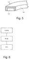
Fig. 5 is a partial sectional view of the squealer tip ofFig. 4 with a cooling passage. -
Fig. 6 is a flow chart showing exemplary steps in repairing a squealer tip as may be described herein. - Referring now to the drawings, in which like numerals refer to like elements throughout the several views,
Fig. 1 shows a schematic view ofgas turbine engine 10 as may be used herein. Thegas turbine engine 10 may include acompressor 15. Thecompressor 15 compresses an incoming flow ofair 20. Thecompressor 15 delivers the compressed flow ofair 20 to acombustor 25. Thecombustor 25 mixes the compressed flow ofair 20 with a pressurized flow offuel 30 and ignites the mixture to create a flow ofcombustion gases 35. Although only asingle combustor 25 is shown, thegas turbine engine 10 may include any number ofcombustors 25. The flow ofcombustion gases 35 is in turn delivered to aturbine 40. The flow ofcombustion gases 35 drives theturbine 40 so as to produce mechanical work. The mechanical work produced in theturbine 40 drives thecompressor 15 via ashaft 45 and anexternal load 50 such as an electrical generator and the like. - The
gas turbine engine 10 may use natural gas, various types of syngas, liquid fuels, and/or other types of fuels and blends thereof. Thegas turbine engine 10 may be any one of a number of different gas turbine engines offered by General Electric Company of Schenectady, New York, including, but not limited to, those such as a 7 or a 9 series heavy duty gas turbine engine and the like. Thegas turbine engine 10 may have different configurations and may use other types of components. Other types of gas turbine engines also may be used herein. Multiple gas turbine engines, other types of turbines, and other types of power generation equipment also may be used herein together. -
Fig. 2 is a perspective view of an example of aturbine blade 55. In this example, theturbine blade 55 may be a stage one bucket although any type of blade may be used herein. Generally described, theturbine blade 55 includes anairfoil 60. Theairfoil 60 may extend from a leadingedge 62 to atrailing edge 64 with a concave pressure sideouter wall 66 and a convex suction sideouter wall 68. Theturbine blade 55 also may include a downwardly extendingshank 70 and an attachment in the form of adovetail 75. Aplatform 80 may extend transversely between theairfoil 60 and theshank 70 and thedovetail 75. The radial end of theairfoil 60 may include asquealer tip 85. Thesquealer tip 85 may be an extension of theouter sidewalls squealer tip 85 may define arecessed tip cap 90 therein. Theturbine blade 55 and thesquealer tip 85 described herein are for the purposes of example only. Many other designs and configurations may be known. - As described above, the
squealer tip 85 may be subjected to high temperatures and may rub against a seal structure such as a stationary shroud. As a result,cracks 95 may develop in thesquealer tip 85 due to thermally induced stress and material loss due to oxidation and the like. In order to repair theturbine blade 55, thesquealer tip 85 may be machined down as is shown inFig. 3 so as to remove thecracks 85 or other types of worn out, damaged, or otherwise defective locations. The squealer tip material may be machined in a conventional fashion. -
Figs. 4 and5 show an improvedturbine blade 100 as may be described herein. Theturbine blade 100 may be theturbine blade 55 described above with thesquealer tip 85 machined down and with an improvedsquealer tip 110 built thereon. The improvedsquealer tip 110 may include asquealer tip extension 120 built thereon so as to extend radially upward from theouter sidewalls squealer tip extension 120 may be built-up in any suitable size, shape, or configuration. - The
improved squealer tip 110 may have one or more cooling passages built into thesquealer tip extension 120 or otherwise. Thecooling passages 130 may have any suitable size, shape, or configuration. Thecooling passages 130 may be in communication with a source of a cooling medium such as air extending through theairfoil 60 from thecompressor 15 or elsewhere. The inside of thecooling passages 130 may have rough surfaces, such as dimples or other types of surface features so as to increase the overall heat transfer effect. An aluminide coating and the like also may be used within thecooling passages 130 to increase the oxygen resistance at elevated temperatures. Other components and other configurations may be used herein. - Instead of conventionally welding or otherwise attaching a squealer tip extension to the
airfoil 60, in this example, thesquealer tip extension 120 may be built up on theairfoil 60 in an additive manufacturing process, i.e., three dimensional printing. Specifically, thesquealer tip extension 120 may be printed or built up via a direct metal laser sintering (DMLS) process and the like in any suitable size, shape, or configuration. DMLS is an additive manufacturing process that uses a laser to sinter a metallic powder material and binds the material together to create a solid structure. Selective laser sintering and other types of sintering and/or melting techniques or other types of additive manufacturing processes and the like also may be used herein to create thesquealer tip 110 or other component. Moreover, the use of a DMLS process or other type of three-dimensional printing allows the creation of thecooling passages 130 or other type of complex internal geometry. The DMLS or other type of three-dimensional printing process allows thecooling passages 130 to be created therein with any desired geometry so as to provide improved cooling thereto. An electron beam (EB) welding process and the like also may be used herein. - Because three dimensional printing is a welding process, materials with adequate weldability may be used. For example, the powdered material adjacent to the
original airfoil 60 may be a superalloy powder in the easy to weld range (Al ≤ - 0.5 Ti + 3 according to the Chart of Strain Age Cracking Susceptibility of Superalloy) for "buttering" or the initial build-up. Suitable materials may include Haynes 230, Haynes 282, and similar materials. A hard to weld superalloy powder (Al ≥ -0.5 Ti + 3) then may be used to build up thesquealer tip extension 120. Suitable materials may include Haynes 214, GTD111, Rene 108, and similar materials. The superalloy materials in general may have high oxidation resistance. Other types of materials also may be used herein. -
Fig. 6 shows a flowchart of exemplary steps in carrying out the methods described herein in whole or in part. At step 140, the existingsquealer tip 85 may be machined down on theairfoil 60 as is shown inFig. 3 . At step 150, a build plate in a DMLS machine or other device may be modified to accept theairfoil 60 of theturbine blade 55. At step 160, the DMLS machine may print or buildup thesquealer tip extension 120 of theimproved squealer tip 110 directly on theairfoil 60. This printing or buildup step also may include the creation of thecooling passages 130 or other types of internal geometries therein. Theimproved turbine blade 100 may now be ready for use or other types of processing. The method steps described herein are not exclusive. Other or different method steps may be used in any desired order to create thesquealer tip 110 or other component herein. - The systems and methods described herein thus provide for the fast and efficient repair of turbine blades and squealer tips with the use of advanced superalloy materials with improved oxidation resistance. Moreover, the
improved turbine blade 100 may include thecooling passage 130 within thesquealer tip 110 for improved cooling and an enhanced overall component lifetime.Such cooling passages 130 generally were not possible given existing manufacturing constraints. Moreover, the systems and methods described herein may be used to upgrade existing turbine blades with such cooling features. - It should be apparent that the foregoing relates only to certain embodiments of the present application and the resultant patent. Numerous changes and modifications may be made herein by one of ordinary skill in the art without departing from the general spirit and scope of the invention as defined by the following claims and the equivalents thereof.
- Various aspects and embodiments of the present invention are defined by the following clauses:
- 1. A method of repairing a turbine blade, comprising:
- removing an existing squealer tip from the turbine blade in whole or in part;
- positioning the turbine blade in an additive manufacturing system; and
- building up an extension of a replacement squealer tip on the turbine blade in whole or in part.
- 2. The method of clause 1, wherein the step of removing an existing squealer tip from the turbine blade comprises machining the existing squealer tip in whole or in part.
- 3. The method of clause 1, wherein the step of positioning the turbine blade in an additive manufacturing system comprises positioning the turbine blade in a direct metal laser sintering system or an electron beam welding system.
- 4. The method of clause 3, wherein the step of positioning the turbine blade in an additive manufacturing system comprises modifying a build plate of the direct metal laser sintering system to accommodate the turbine blade.
- 5. The method of clause 1, wherein the step of building up an extension of a replacement squealer tip comprising direct metal laser sintering.
- 6. The method of clause 1, wherein the step of building up an extension of a replacement squealer tip comprises sintering and binding a metallic powder material.
- 7. The method of clause 6, wherein the step of sintering and binding a metallic powder material comprises sintering and binding a superalloy powder with Al≤-0.5 Ti+3.
- 8. The method of clause 6, wherein the step of sintering and binding a metallic powder material comprises sintering and binding a superalloy powder with Al≥-0.5 Ti+3.
- 9. The method of clause 6, wherein the step of sintering and binding a metallic powder material comprises sintering and binding a superalloy powder with high oxidation resistance.
- 10. The method of clause 1, wherein the step of building up an extension of a replacement squealer tip comprises creating a cooling passage within the extension.
- 11. The method of
clause 10, wherein the step of building up an extension of a replacement squealer tip comprises creating a cooling passage within the extension with a rough surface therein. - 12. The method of
clause 10, wherein the step of building up an extension of a replacement squealer tip comprises creating a cooling passage within the extension with an aluminide coating. - 13. A turbine blade for use in a gas turbine engine, comprising:
- an airfoil; and
- a squealer tip built up on the airfoil;
- the squealer tip comprising a cooling passage therein;
- the squealer tip comprising a superalloy suitable for an additive manufacturing process.
- 14. The turbine blade of clause 13, wherein the squealer tip comprises a replacement squealer tip.
- 15. The turbine blade of clause 13, wherein the squealer tip comprises a squealer tip extension built up on the airfoil.
- 16. A method of repairing a turbine blade, comprising:
- removing an existing squealer tip from the turbine blade in whole or in part;
- positioning the turbine blade in an additive manufacturing system;
- building up a superalloy extension of a replacement squealer tip on the turbine blade in whole or in part; and
- creating a cooling passage through the superalloy extension.
- 17. The method of clause 16, wherein the step of removing an existing squealer tip from the turbine blade comprises machining the existing squealer tip in whole or in part.
- 18. The method of clause 16, wherein the step of positioning the turbine blade in an additive manufacturing system comprises positioning the turbine blade in a direct metal laser sintering system or an electron beam welding system.
- 19. The method of clause 18, wherein the step of positioning the turbine blade in an additive manufacturing system comprises modifying a build plate of the direct metal laser sintering system to accommodate the turbine blade.
- 20. The method of clause 16, wherein the step of building up a superalloy extension of a replacement squealer tip comprising direct metal laser sintering a metallic powder material.
Claims (15)
- A method of repairing a turbine blade (100), comprising:removing an existing squealer tip (85) from the turbine blade (100) in whole or in part;positioning the turbine blade (100) in an additive manufacturing system; andbuilding up an extension (120) of a replacement squealer tip (110) on the turbine blade (100) in whole or in part.
- The method of claim 1, wherein the step of removing an existing squealer tip (85) from the turbine blade (100) comprises machining the existing squealer tip (85) in whole or in part.
- The method of claim 1, wherein the step of positioning the turbine blade (100) in an additive manufacturing system comprises positioning the turbine blade (100) in a direct metal laser sintering system or an electron beam welding system.
- The method of claim 3, wherein the step of positioning the turbine blade (100) in an additive manufacturing system comprises modifying a build plate of the direct metal laser sintering system to accommodate the turbine blade (100).
- The method of claim 1, wherein the step of building up an extension (120) of a replacement squealer tip (110) comprising direct metal laser sintering.
- The method of claim 1, wherein the step of building up an extension (120) of a replacement squealer tip (110) comprises sintering and binding a metallic powder material.
- The method of claim 6, wherein the step of sintering and binding a metallic powder material comprises sintering and binding a superalloy powder with Al≤-0.5 Ti+3.
- The method of claim 6, wherein the step of sintering and binding a metallic powder material comprises sintering and binding a superalloy powder with Al≥-0.5 Ti+3.
- The method of claim 6, wherein the step of sintering and binding a metallic powder material comprises sintering and binding a superalloy powder with high oxidation resistance.
- The method of claim 1, wherein the step of building up an extension (120) of a replacement squealer tip (110) comprises creating a cooling passage (130) within the extension (120).
- The method of claim 10, wherein the step of building up an extension (120) of a replacement squealer tip (110) comprises creating a cooling passages (130) within the extension (120) with a rough surface therein.
- The method of claim 10, wherein the step of building up an extension (120) of a replacement squealer tip (110) comprises creating a cooling passage (130) within the extension (120) with an aluminide coating therein.
- A turbine blade (100) for use in a gas turbine engine (10), comprising:an airfoil (60); anda squealer tip (110) built up on the airfoil (60);the squealer tip (110) comprising a cooling passage (130) therein;the squealer tip (110) comprising a superalloy suitable for an additive manufacturing process.
- The turbine blade (100) of claim 13, wherein the squealer tip (110) comprises a replacement squealer tip (110).
- The turbine blade (100) of claim 13, wherein the squealer tip (110) comprises a squealer tip extension (120) built up on the airfoil (60).
Applications Claiming Priority (1)
| Application Number | Priority Date | Filing Date | Title |
|---|---|---|---|
| US14/794,838 US20170009584A1 (en) | 2015-07-09 | 2015-07-09 | Systems and Methods for Turbine Blade Repair |
Publications (1)
| Publication Number | Publication Date |
|---|---|
| EP3115147A1 true EP3115147A1 (en) | 2017-01-11 |
Family
ID=56740787
Family Applications (1)
| Application Number | Title | Priority Date | Filing Date |
|---|---|---|---|
| EP16177837.8A Pending EP3115147A1 (en) | 2015-07-09 | 2016-07-04 | Systems and methods for turbine blade repair |
Country Status (4)
| Country | Link |
|---|---|
| US (1) | US20170009584A1 (en) |
| EP (1) | EP3115147A1 (en) |
| JP (1) | JP2017020501A (en) |
| CN (1) | CN106337696A (en) |
Cited By (2)
| Publication number | Priority date | Publication date | Assignee | Title |
|---|---|---|---|---|
| EP3434395A1 (en) * | 2017-07-24 | 2019-01-30 | General Electric Company | Method for repairing a component by additive manufacturing |
| EP3466602A1 (en) * | 2017-09-25 | 2019-04-10 | General Electric Company | Method for forming article, method for forming turbine bucket, and turbine bucket |
Families Citing this family (28)
| Publication number | Priority date | Publication date | Assignee | Title |
|---|---|---|---|---|
| DE102017201994A1 (en) * | 2017-02-08 | 2018-08-09 | Siemens Aktiengesellschaft | Method and apparatus for the powder bed-based additive construction of a plurality of similar components |
| US10610933B2 (en) | 2017-02-22 | 2020-04-07 | General Electric Company | Method of manufacturing turbine airfoil with open tip casting and tip component thereof |
| US10717130B2 (en) | 2017-02-22 | 2020-07-21 | General Electric Company | Method of manufacturing turbine airfoil and tip component thereof |
| US11154956B2 (en) | 2017-02-22 | 2021-10-26 | General Electric Company | Method of repairing turbine component using ultra-thin plate |
| US10625342B2 (en) | 2017-02-22 | 2020-04-21 | General Electric Company | Method of repairing turbine component |
| US10702958B2 (en) | 2017-02-22 | 2020-07-07 | General Electric Company | Method of manufacturing turbine airfoil and tip component thereof using ceramic core with witness feature |
| US10995619B2 (en) | 2017-05-26 | 2021-05-04 | General Electric Company | Airfoil and method of fabricating same |
| US11027368B2 (en) * | 2017-08-02 | 2021-06-08 | General Electric Company | Continuous additive manufacture of high pressure turbine |
| US11426818B2 (en) | 2018-08-10 | 2022-08-30 | The Research Foundation for the State University | Additive manufacturing processes and additively manufactured products |
| US11465245B2 (en) | 2019-01-30 | 2022-10-11 | General Electric Company | Tooling assembly for magnetically aligning components in an additive manufacturing machine |
| US11144034B2 (en) | 2019-01-30 | 2021-10-12 | General Electric Company | Additive manufacturing systems and methods of generating CAD models for additively printing on workpieces |
| US11198182B2 (en) | 2019-01-30 | 2021-12-14 | General Electric Company | Additive manufacturing systems and methods of additively printing on workpieces |
| US11426799B2 (en) | 2019-01-30 | 2022-08-30 | General Electric Company | Powder seal assembly for decreasing powder usage in a powder bed additive manufacturing process |
| US11285538B2 (en) | 2019-01-30 | 2022-03-29 | General Electric Company | Tooling assembly and method for aligning components for a powder bed additive manufacturing repair process |
| US11458681B2 (en) | 2019-01-30 | 2022-10-04 | General Electric Company | Recoating assembly for an additive manufacturing machine |
| US11173574B2 (en) | 2019-01-30 | 2021-11-16 | General Electric Company | Workpiece-assembly and additive manufacturing systems and methods of additively printing on workpieces |
| US20200238386A1 (en) | 2019-01-30 | 2020-07-30 | General Electric Company | Tooling Assembly for Decreasing Powder Usage in a Powder Bed Additive Manufacturing Process |
| US11407035B2 (en) | 2019-01-30 | 2022-08-09 | General Electric Company | Powder seal assembly for decreasing powder usage in a powder bed additive manufacturing process |
| US11498132B2 (en) | 2019-01-30 | 2022-11-15 | General Electric Company | Additive manufacturing systems and methods of calibrating for additively printing on workpieces |
| US11344979B2 (en) | 2019-01-30 | 2022-05-31 | General Electric Company | Build plate clamping-assembly and additive manufacturing systems and methods of additively printing on workpieces |
| DE102019207479A1 (en) * | 2019-05-22 | 2020-11-26 | Siemens Aktiengesellschaft | Method for carrying out service measures on an energy conversion system and energy conversion system |
| CN110202158A (en) * | 2019-05-23 | 2019-09-06 | 中国人民解放军第五七一九工厂 | A kind of monoblock type restorative procedure of aero-turbine rotor blade integral shroud longitudinal direction heavy break |
| US11298884B2 (en) | 2019-06-07 | 2022-04-12 | General Electric Company | Additive manufacturing systems and methods of pretreating and additively printing on workpieces |
| DE102019208703A1 (en) * | 2019-06-14 | 2020-12-17 | MTU Aero Engines AG | ROTATING BLADE FOR A FLOW MACHINE |
| CN113441725B (en) * | 2020-03-27 | 2023-09-22 | 斗山重工业建设有限公司 | Method for repairing turbine blade by using additive manufacturing |
| US12377469B2 (en) | 2021-03-02 | 2025-08-05 | General Electric Company | Recoater for additive manufacturing |
| US12503944B2 (en) | 2022-09-29 | 2025-12-23 | Ge Infrastructure Technology Llc | Method of machining turbine components using a reference surface |
| CN117685249B (en) * | 2024-01-12 | 2024-09-27 | 广东肇庆德通有限公司 | Diagonal flow fan with partial blade top grooves |
Citations (7)
| Publication number | Priority date | Publication date | Assignee | Title |
|---|---|---|---|---|
| EP1721697A1 (en) * | 2005-05-06 | 2006-11-15 | United Technologies Corporation | Superalloy repair methods and inserts |
| EP2159376A2 (en) * | 2008-08-28 | 2010-03-03 | United Technologies Corporation | Airfoil insert and method for cooling an airfoil |
| US20100200189A1 (en) * | 2009-02-12 | 2010-08-12 | General Electric Company | Method of fabricating turbine airfoils and tip structures therefor |
| EP2395199A2 (en) * | 2010-06-14 | 2011-12-14 | Kabushiki Kaisha Toshiba | Method for repairing gas turbine blades and a gas turbine blade |
| FR2962357A1 (en) * | 2010-07-09 | 2012-01-13 | Snecma | Repairing/reloading metal piece of turbomachine e.g. turboreactor, by determining geometry of piece, positioning and fixing piece on plate, positioning mask on plate and piece, and depositing thin metallic powder layer on surface of mask |
| WO2014121060A1 (en) * | 2013-01-31 | 2014-08-07 | Siemens Energy, Inc. | Localized repair of superalloy component |
| US20150034266A1 (en) * | 2013-08-01 | 2015-02-05 | Siemens Energy, Inc. | Building and repair of hollow components |
Family Cites Families (10)
| Publication number | Priority date | Publication date | Assignee | Title |
|---|---|---|---|---|
| US6908288B2 (en) * | 2001-10-31 | 2005-06-21 | General Electric Company | Repair of advanced gas turbine blades |
| US8511991B2 (en) * | 2009-12-07 | 2013-08-20 | General Electric Company | Composite turbine blade and method of manufacture thereof |
| US9283593B2 (en) * | 2011-01-13 | 2016-03-15 | Siemens Energy, Inc. | Selective laser melting / sintering using powdered flux |
| US9085980B2 (en) * | 2011-03-04 | 2015-07-21 | Honeywell International Inc. | Methods for repairing turbine components |
| US20130104397A1 (en) * | 2011-10-28 | 2013-05-02 | General Electric Company | Methods for repairing turbine blade tips |
| US9186757B2 (en) * | 2012-05-09 | 2015-11-17 | Siemens Energy, Inc. | Method of providing a turbine blade tip repair |
| US20140216042A1 (en) * | 2012-09-28 | 2014-08-07 | United Technologies Corporation | Combustor component with cooling holes formed by additive manufacturing |
| EP2900964A4 (en) * | 2012-09-28 | 2016-06-29 | United Technologies Corp | Uber-cooled turbine section component made by additive manufacturing |
| WO2015069411A1 (en) * | 2013-11-11 | 2015-05-14 | United Technologies Corporation | Gas turbine engine turbine blade tip cooling |
| US9803939B2 (en) * | 2013-11-22 | 2017-10-31 | General Electric Company | Methods for the formation and shaping of cooling channels, and related articles of manufacture |
-
2015
- 2015-07-09 US US14/794,838 patent/US20170009584A1/en not_active Abandoned
-
2016
- 2016-06-28 JP JP2016127128A patent/JP2017020501A/en active Pending
- 2016-07-04 EP EP16177837.8A patent/EP3115147A1/en active Pending
- 2016-07-08 CN CN201610535062.1A patent/CN106337696A/en active Pending
Patent Citations (7)
| Publication number | Priority date | Publication date | Assignee | Title |
|---|---|---|---|---|
| EP1721697A1 (en) * | 2005-05-06 | 2006-11-15 | United Technologies Corporation | Superalloy repair methods and inserts |
| EP2159376A2 (en) * | 2008-08-28 | 2010-03-03 | United Technologies Corporation | Airfoil insert and method for cooling an airfoil |
| US20100200189A1 (en) * | 2009-02-12 | 2010-08-12 | General Electric Company | Method of fabricating turbine airfoils and tip structures therefor |
| EP2395199A2 (en) * | 2010-06-14 | 2011-12-14 | Kabushiki Kaisha Toshiba | Method for repairing gas turbine blades and a gas turbine blade |
| FR2962357A1 (en) * | 2010-07-09 | 2012-01-13 | Snecma | Repairing/reloading metal piece of turbomachine e.g. turboreactor, by determining geometry of piece, positioning and fixing piece on plate, positioning mask on plate and piece, and depositing thin metallic powder layer on surface of mask |
| WO2014121060A1 (en) * | 2013-01-31 | 2014-08-07 | Siemens Energy, Inc. | Localized repair of superalloy component |
| US20150034266A1 (en) * | 2013-08-01 | 2015-02-05 | Siemens Energy, Inc. | Building and repair of hollow components |
Cited By (3)
| Publication number | Priority date | Publication date | Assignee | Title |
|---|---|---|---|---|
| EP3434395A1 (en) * | 2017-07-24 | 2019-01-30 | General Electric Company | Method for repairing a component by additive manufacturing |
| US10919119B2 (en) | 2017-07-24 | 2021-02-16 | General Electric Company | Method for repairing a component by additive manufacturing |
| EP3466602A1 (en) * | 2017-09-25 | 2019-04-10 | General Electric Company | Method for forming article, method for forming turbine bucket, and turbine bucket |
Also Published As
| Publication number | Publication date |
|---|---|
| US20170009584A1 (en) | 2017-01-12 |
| JP2017020501A (en) | 2017-01-26 |
| CN106337696A (en) | 2017-01-18 |
Similar Documents
| Publication | Publication Date | Title |
|---|---|---|
| EP3115147A1 (en) | Systems and methods for turbine blade repair | |
| CN106903478B (en) | System and method for deep peripheral crack repair | |
| US9868180B2 (en) | Turbine blade tip repair using dual fusion welding | |
| US6494677B1 (en) | Turbine nozzle segment and method of repairing same | |
| CN103084780B (en) | Method for repairing turbine bucket tip | |
| CA2647767C (en) | Method for repairing a turbine nozzle segment | |
| US6905308B2 (en) | Turbine nozzle segment and method of repairing same | |
| US10875131B2 (en) | Repair or remanufacture of blade platform for a gas turbine engine | |
| US9694440B2 (en) | Support collar geometry for linear friction welding | |
| JP2005201242A (en) | How to repair a gas turbine rotor blade | |
| EP1967697A2 (en) | Turbine nozzle segment and repair method | |
| US9828857B2 (en) | Repaired or remanufactured blade platform for a gas turbine engine | |
| US20250091147A1 (en) | Methods for joining components at narrow, uniform braze joints | |
| KR20260037301A (en) | Methods for joining components at narrow, uniform braze joints |
Legal Events
| Date | Code | Title | Description |
|---|---|---|---|
| PUAI | Public reference made under article 153(3) epc to a published international application that has entered the european phase |
Free format text: ORIGINAL CODE: 0009012 |
|
| AK | Designated contracting states |
Kind code of ref document: A1 Designated state(s): AL AT BE BG CH CY CZ DE DK EE ES FI FR GB GR HR HU IE IS IT LI LT LU LV MC MK MT NL NO PL PT RO RS SE SI SK SM TR |
|
| AX | Request for extension of the european patent |
Extension state: BA ME |
|
| STAA | Information on the status of an ep patent application or granted ep patent |
Free format text: STATUS: REQUEST FOR EXAMINATION WAS MADE |
|
| 17P | Request for examination filed |
Effective date: 20170711 |
|
| RBV | Designated contracting states (corrected) |
Designated state(s): AL AT BE BG CH CY CZ DE DK EE ES FI FR GB GR HR HU IE IS IT LI LT LU LV MC MK MT NL NO PL PT RO RS SE SI SK SM TR |