EP3114528B1 - Sparse projection for a virtual reality system - Google Patents
Sparse projection for a virtual reality system Download PDFInfo
- Publication number
- EP3114528B1 EP3114528B1 EP16759552.9A EP16759552A EP3114528B1 EP 3114528 B1 EP3114528 B1 EP 3114528B1 EP 16759552 A EP16759552 A EP 16759552A EP 3114528 B1 EP3114528 B1 EP 3114528B1
- Authority
- EP
- European Patent Office
- Prior art keywords
- clusters
- headset
- light
- local area
- diffractive optical
- Prior art date
- Legal status (The legal status is an assumption and is not a legal conclusion. Google has not performed a legal analysis and makes no representation as to the accuracy of the status listed.)
- Active
Links
Images


Classifications
-
- G—PHYSICS
- G02—OPTICS
- G02B—OPTICAL ELEMENTS, SYSTEMS OR APPARATUS
- G02B27/00—Optical systems or apparatus not provided for by any of the groups G02B1/00 - G02B26/00, G02B30/00
- G02B27/01—Head-up displays
- G02B27/017—Head mounted
- G02B27/0172—Head mounted characterised by optical features
-
- G—PHYSICS
- G02—OPTICS
- G02B—OPTICAL ELEMENTS, SYSTEMS OR APPARATUS
- G02B27/00—Optical systems or apparatus not provided for by any of the groups G02B1/00 - G02B26/00, G02B30/00
- G02B27/01—Head-up displays
- G02B27/017—Head mounted
-
- G—PHYSICS
- G03—PHOTOGRAPHY; CINEMATOGRAPHY; ANALOGOUS TECHNIQUES USING WAVES OTHER THAN OPTICAL WAVES; ELECTROGRAPHY; HOLOGRAPHY
- G03B—APPARATUS OR ARRANGEMENTS FOR TAKING PHOTOGRAPHS OR FOR PROJECTING OR VIEWING THEM; APPARATUS OR ARRANGEMENTS EMPLOYING ANALOGOUS TECHNIQUES USING WAVES OTHER THAN OPTICAL WAVES; ACCESSORIES THEREFOR
- G03B21/00—Projectors or projection-type viewers; Accessories therefor
- G03B21/14—Details
-
- G—PHYSICS
- G06—COMPUTING OR CALCULATING; COUNTING
- G06F—ELECTRIC DIGITAL DATA PROCESSING
- G06F3/00—Input arrangements for transferring data to be processed into a form capable of being handled by the computer; Output arrangements for transferring data from processing unit to output unit, e.g. interface arrangements
- G06F3/01—Input arrangements or combined input and output arrangements for interaction between user and computer
- G06F3/011—Arrangements for interaction with the human body, e.g. for user immersion in virtual reality
-
- G—PHYSICS
- G06—COMPUTING OR CALCULATING; COUNTING
- G06T—IMAGE DATA PROCESSING OR GENERATION, IN GENERAL
- G06T19/00—Manipulating 3D models or images for computer graphics
- G06T19/006—Mixed reality
-
- G—PHYSICS
- G02—OPTICS
- G02B—OPTICAL ELEMENTS, SYSTEMS OR APPARATUS
- G02B27/00—Optical systems or apparatus not provided for by any of the groups G02B1/00 - G02B26/00, G02B30/00
- G02B27/01—Head-up displays
- G02B27/0101—Head-up displays characterised by optical features
- G02B2027/0138—Head-up displays characterised by optical features comprising image capture systems, e.g. camera
-
- G—PHYSICS
- G02—OPTICS
- G02B—OPTICAL ELEMENTS, SYSTEMS OR APPARATUS
- G02B27/00—Optical systems or apparatus not provided for by any of the groups G02B1/00 - G02B26/00, G02B30/00
- G02B27/01—Head-up displays
- G02B27/0101—Head-up displays characterised by optical features
- G02B2027/014—Head-up displays characterised by optical features comprising information/image processing systems
-
- G—PHYSICS
- G02—OPTICS
- G02B—OPTICAL ELEMENTS, SYSTEMS OR APPARATUS
- G02B27/00—Optical systems or apparatus not provided for by any of the groups G02B1/00 - G02B26/00, G02B30/00
- G02B27/01—Head-up displays
- G02B27/017—Head mounted
- G02B27/0172—Head mounted characterised by optical features
- G02B2027/0174—Head mounted characterised by optical features holographic
-
- G—PHYSICS
- G02—OPTICS
- G02B—OPTICAL ELEMENTS, SYSTEMS OR APPARATUS
- G02B27/00—Optical systems or apparatus not provided for by any of the groups G02B1/00 - G02B26/00, G02B30/00
- G02B27/01—Head-up displays
- G02B27/0179—Display position adjusting means not related to the information to be displayed
- G02B2027/0187—Display position adjusting means not related to the information to be displayed slaved to motion of at least a part of the body of the user, e.g. head, eye
Definitions
- the present disclosure generally relates to virtual reality systems, and more specifically relates to projection systems for virtual reality systems.
- VR systems include components for determining position and movement of a VR headset worn by a user.
- Conventional VR systems determine position and movement of a VR headset through active devices (e.g., light emitting diodes) that emit light used by the VR system to track the location of the VR headset.
- active devices e.g., light emitting diodes
- using active components to track position and movement VR headsets increases the complexity of design and manufacture of VR headsets.
- US 2009/231270 A1 discloses a technique for tracking head movements of a user wearing a head-mounted display based on groups of glyphs that are projected onto the environment surrounding the user and captured with a camera attached to the user's head.
- Each group of glyphs comprises four L-shaped glyphs, each of which arrangeable in one of four possible orientations.
- a two-dimensional coordinate can be encoded by the group of glyphs.
- the system adopts a primary-secondary marker deployment solution, in which the primary marker uses an improved two-dimensional barcode and can be identified uniquely.
- the secondary marker is a simple light-spot, whose code is identified through the location relationship with the nearby primary markers and is used for calculating the pose of a virtual reality headset worn by a user.
- the system tracks the invisible markers using an infrared camera mounted to the virtual reality headset.
- US 2014/160162 A1 discloses a virtual or augmented reality system comprising a surface projection device and a visor worn by a user.
- the surface projection device and the visor work together to create virtual objects that are located on specific coordinates on predefined patterns that are projected by the surface projection device on a surface.
- An image capturing system of the visor captures the patterns and extracts feature points in the predefined patterns. According to the image capturing device or internal parameters, the camera's 3D transformation matrix is calculated based on matching feature points. The camera's relative position and orientation to the surface is estimated and is used for VR/AR content overlaying.
- US 2013/169941 A1 discloses a projection system for projecting video information with high efficiency.
- the projection system comprises a plurality of hologram recording media (e.g. Fourier transform type hologram recording media) and an irradiation device that generates a plurality of coherent light beams.
- Each of the plurality of hologram recording media is configured to diffract a corresponding one of the plurality of light beams, so as to generate with high efficiency a corresponding portion of the video information.
- a virtual reality (VR) system includes a VR headset including an imaging device, a sparse projection system, and a VR console.
- the sparse projection system generates a plurality of clusters using one or more diffractive optical elements and projects the clusters throughout a local area including the sparse projection system.
- Each cluster has a unique location configuration that corresponds to a unique location in a virtual mapping of the local area including the sparse projection system.
- the VR headset includes an imaging device configured to capture a series of images of portions of the local area, with one or more of the images including at least one cluster.
- the VR headset includes an electronic display configured to output content based at least in part on the virtual mapping of the local area.
- the VR console receives the series of images from the imaging device of the VR headset and determines a location of the VR headset within the virtual mapping of the local area based at least in part on a location configuration of the at least one cluster in the series of images. For example, based at least in part on the determined location of the VR headset within the virtual mapping of the local area, the VR console generates content that is provided to the VR headset for presentation by the electronic display.
- FIG. 1 is a block diagram of a virtual reality (VR) system environment 100 in which a VR console 110 operates.
- the system environment 100 shown by FIG. 1 comprises a VR headset 105 that includes an imaging device 135, a sparse projection system 136, and a VR input interface 140 that are each coupled to the VR console 110.
- FIG. 1 shows an example system environment 100 including one VR headset 105, one sparse projection system 136, and one VR input interface 140, in other embodiments any number of these components may be included in the system environment 100.
- each VR headset 105, VR input interface 140, sparse projection system 136, and imaging device 135 communicates with the VR console 110.
- different and/or additional components may be included in the system environment 100.
- the sparse projection system 136 includes one or more sparse projectors that generate and project a plurality of clusters throughout a local area that includes the sparse projection system 136.
- the sparse projection system 136 includes one or more light sources that emit coherent light at specific bands (e.g., a range of wavelengths of light).
- Example bands of light emitted by one or more light sources in the sparse projection system 136 include a visible band ( ⁇ 380 nm to 750 nm), an infrared (IR) band ( ⁇ 750 nm to 1 mm), an ultraviolet band (10 nm to 380 nm), another portion of the electromagnetic spectrum, or some combination thereof.
- a light source in the sparse projection system 136 is a laser producing light in the IR band.
- one or more diffractive optical elements are illuminated by the one or more light sources in the sparse projection system 136.
- the generated plurality of clusters are then projected into the local area by the sparse projection system 136.
- Sparse projection systems 136 are further described below in conjunction with FIGS. 4 and 5 .
- a cluster is a unique pattern or configuration of illuminated regions that corresponds to a unique location in a virtual mapping of the local area including the sparse projection systems 136.
- different clusters are associated with different locations in the virtual mapping of the local area, which is a real world environment onto which the sparse projection system 136 projects the clusters.
- a local area is an interior of a room enclosing a sparse projection system 136 that projects clusters onto one or more surfaces within the room.
- Each cluster includes various illuminated regions that have a unique location configuration, which describes a spatial configuration of a cluster and a reflectance type of the cluster.
- the spatial configuration of a cluster describes a number and an arrangement of illuminated regions within the cluster, while the reflectance type specifies a band of light (e.g., a range of wavelengths of light) used to generate the cluster.
- a band of light e.g., a range of wavelengths of light
- No two clusters have the same unique location configuration.
- each cluster has a different spatial configuration, but have a common reflectance type.
- multiple clusters may have the same spatial configuration but have different reflectance types.
- the VR headset 105 is a head-mounted display that presents content to a user. Examples of content presented by the VR headset 105 includes one or more images, video, audio, or some combination thereof. In some embodiments, audio is presented via an external device (e.g., speakers and/or headphones) that receives audio information from the VR headset 105, the VR console 110, or both, and presents audio data based on the audio information. An embodiment of the VR headset 105 is further described below in conjunction with FIG. 2 .
- the VR headset 105 may comprise one or more rigid bodies, which may be rigidly or non-rigidly coupled to each other together. A rigid coupling between rigid bodies causes the coupled rigid bodies to act as a single rigid entity.
- the VR headset 105 may also act as an augmented reality (AR) headset and/or a mixed reality (MR) headset. In these embodiments, the VR headset 105 augments views of a physical, real-world environment with computer-generated content (e.g., images, video, sound, etc.).
- AR augmented reality
- MR mixed reality
- the VR headset 105 augments views of a physical, real-world environment with computer-generated content (e.g., images, video, sound, etc.).
- the VR headset 105 includes an electronic display 115, an optics block 118, one or more position sensors 125, an inertial measurement unit (IMU) 130, and an imaging device 135.
- the electronic display 115 displays images to the user in accordance with data received from the VR console 110.
- the electronic display 115 may comprise a single electronic display or multiple electronic displays (e.g., a display for each eye of a user). Examples of the electronic display 115 include: a liquid crystal display (LCD), an organic light emitting diode (OLED) display, an active-matrix organic light-emitting diode display (AMOLED), some other display, or some combination thereof.
- LCD liquid crystal display
- OLED organic light emitting diode
- AMOLED active-matrix organic light-emitting diode display
- the optics block 118 magnifies received image light, corrects optical errors associated with the image light, and presents the corrected image light to a user of the VR headset 105.
- the optics block 118 includes one or more optical elements.
- Example optical elements included in the optics block 118 include: an aperture, a Fresnel lens, a convex lens, a concave lens, a filter, or any other suitable optical element that affects image light.
- the optics block 118 may include combinations of different optical elements.
- one or more of the optical elements in the optics block 118 may have one or more coatings, such as anti-reflective coatings.
- Magnification of the image light by the optics block 118 allows the electronic display 115 to be physically smaller, weigh less, and consume less power than larger displays. Additionally, magnification may increase a field of view of the content presented by the electronic display 115. For example, the field of view of the displayed content is such that the displayed content is presented using almost all (e.g., 110 degrees diagonal), and in some cases all, of the user's field of view. In some embodiments, the amount of magnification may be adjusted by adding or removing optical elements.
- the optics block 118 may be designed to correct one or more types of optical error.
- optical error examples include two dimensional optical errors, three dimensional optical errors, or some combination thereof.
- Two dimensional errors are optical aberrations that occur in two dimensions.
- Example types of two dimensional errors include: barrel distortion, pincushion distortion, longitudinal chromatic aberration, transverse chromatic aberration, or any other type of two-dimensional optical error.
- Three dimensional errors are optical errors that occur in three dimensions.
- Example types of three dimensional errors include spherical aberration, comatic aberration, field curvature, astigmatism, or any other type of three-dimensional optical error.
- content provided to the electronic display 115 for display is pre-distorted, so the optics block 118 corrects the distortion when it receives image light from the electronic display 115 generated based on the content.
- the IMU 130 is an electronic device that generates fast calibration data indicating an estimated position of the VR headset 105 relative to an initial position of the VR headset 105 based on measurement signals received from one or more of the position sensors 125.
- a position sensor 125 generates one or more measurement signals in response to motion of the VR headset 105.
- Examples of position sensors 125 include: one or more accelerometers, one or more gyroscopes, one or more magnetometers, another suitable type of sensor that detects motion, a type of sensor used for error correction of the IMU 130, or some combination thereof.
- the position sensors 125 may be located external to the IMU 130, internal to the IMU 130, or some combination thereof.
- the IMU 130 Based on the one or more measurement signals generated by the one or more position sensors 125, the IMU 130 generates fast calibration data indicating an estimated position of the VR headset 105 relative to an initial position of the VR headset 105.
- the position sensors 125 include multiple accelerometers to measure translational motion (forward/back, up/down, left/right) and multiple gyroscopes to measure rotational motion (e.g., pitch, yaw, roll).
- the IMU 130 rapidly samples the measurement signals from various position sensors 125 and calculates the estimated position of the VR headset 105 from the sampled data.
- the IMU 130 integrates the measurement signals received from one or more accelerometers over time to estimate a velocity vector and integrates the velocity vector over time to determine an estimated position of a reference point on the VR headset 105.
- the IMU 130 provides the sampled measurement signals to the VR console 110, which determines the fast calibration data.
- the reference point is a point that may be used to describe the position of the VR headset 105. While the reference point may generally be defined as a point in space, in practice the reference point is defined as a point within the VR headset 105 (e.g., a center of the IMU 130).
- the IMU 130 receives one or more calibration parameters from the VR console 110. As further discussed below, the one or more calibration parameters are used to maintain tracking of the VR headset 105. Based on a received calibration parameter, the IMU 130 may adjust one or more IMU parameters (e.g., sample rate). In some embodiments, certain calibration parameters cause the IMU 130 to update an initial position of the reference point so the initial position of the reference point corresponds to a next calibrated position of the reference point. Updating the initial position of the reference point as the next calibrated position of the reference point helps reduce accumulated error associated with the determined estimated position. The accumulated error, also referred to as drift error, causes the estimated position of the reference point to "drift" away from the actual position of the reference point over time.
- drift error causes the estimated position of the reference point to "drift" away from the actual position of the reference point over time.
- the imaging device 135 captures one or more images of the local area including the VR headset 105, with at least a set of the captured images including at least one cluster.
- the imaging device 135 may include one or more cameras, one or more video cameras, any other device capable of capturing images of the clusters, or some combination thereof. Additionally, the imaging device 135 may include one or more filters (e.g., for increasing signal to noise ratio).
- the imaging device 135 is configured to detect clusters in a field of view of the imaging device 135.
- the images captured by the imaging device 135 are slow calibration data that is communicated from the imaging device 135 to the VR console 110.
- the imaging device 135 receives one or more calibration parameters from the VR console 110 to adjust one or more imaging parameters (e.g., focal length, focus, frame rate, ISO, sensor temperature, shutter speed, aperture, etc.) for capturing images of the local area.
- one or more imaging parameters e.g., focal length, focus, frame rate, ISO, sensor temperature, shutter speed, aperture, etc.
- the imaging device 135 is separate from the VR headset 105.
- the VR input interface 140 is a device that allows a user to send action requests to the VR console 110.
- An action request is a request to perform a particular action.
- An action request may be to start an application, to end an application, or to perform a particular action within the application.
- the VR input interface 140 may include one or more input devices.
- Example input devices include: a keyboard, a mouse, a game controller, a joystick, a yoke, or any other suitable device for receiving action requests and communicating the received action requests to the VR console 110.
- An action request received by the VR input interface 140 is communicated to the VR console 110, which performs an action corresponding to the action request.
- the VR input interface 140 may also include an imaging device 135 that captures images of one or more clusters and provides the images to the VR console 110.
- the VR input interface 140 may also include an IMU 130 that captures fast calibration data indicating an estimated position of the VR input interface 140 relative to an initial position of the VR interface 140 and provides the fast calibration data to the VR console 110.
- the IMU 130 receives one or more calibration parameters from the VR console 110. As further discussed below, the one or more calibration parameters are used to maintain tracking of the VR interface 140.
- the VR input interface 140 may provide haptic feedback to the user in accordance with instructions received from the VR console 110 in some embodiments. For example, haptic feedback is provided to the user when an action request is received. As another example, the VR input interface 140 provides haptic feedback to the user when the VR console 110 communicates instructions to the VR input interface 140 causing the VR input interface 140 to generate haptic feedback when the VR console 110 performs an action.
- the VR console 110 provides content to the VR headset 105 for presentation to the user in accordance with information received from one or more of: the imaging device 135, the VR headset 105, and the VR input interface 140.
- the VR console 110 includes an application store 145, a feature database 147, a mapping module 148, a tracking module 150, and a virtual reality (VR) engine 155.
- Some embodiments of the VR console 110 have different components than those described in conjunction with FIG. 1 .
- the functions further described below may be distributed among components of the VR console 110 in different manners than described here in various embodiments.
- the application store 145 stores one or more applications for execution by the VR console 110.
- An application is a group of instructions, that when executed by a processor, generates content for presentation to the user. Content generated by an application may be in response to inputs received from the user via movement of the VR headset 105 or of the VR interface device 140. Examples of applications include: gaming applications, conferencing applications, video playback application, or other suitable applications.
- the feature database 147 stores a mapping of cross ratios to corresponding clusters in a virtual mapping of the local area.
- a cross ratio of a cluster is based on distances between various illuminated regions within the cluster. For example, a cross ratio of a cluster is determined from distances between pairs of coplanar illuminated regions within the cluster. As a specific example, for a cluster, a product of a distance between a first illuminated region and a second illuminated region and a distance between a third illuminated region and a fourth illuminated region is determined as well as an additional product of a distance between the first illuminated region and the fourth illuminated region and a distance between the third illuminated region and the second illuminated region.
- a cross ratio for the cluster is determined as a ratio of the product to the additional product, with the cross ratio stored in the feature database 147 in association with a cluster identifier associated with the cluster. Additionally, in some embodiments, a cross ratio is also associated with a reflectance type (e.g., a particular band in the IR). Accordingly, in some embodiments, a cross ratio and an additional cross ratio have the same spatial configurations, but have different reflectance types, so the cross ratio and the additional cross ratio map to different areas in the local area. Each cluster in a virtual mapping of a local area is uniquely identified by a cluster identifier. Hence, the feature database 147 stores a mapping between various cluster identifiers and their respective cross ratios.
- the mapping module 148 generates a virtual mapping of the local area based on the images of projected clusters received from the VR headset 105 or from the VR input interface 140. Additionally, the mapping module 148 determines a location of each cluster in the local area relative to the sparse projection system 136 and to the VR headset 105. For example, the mapping module 148 uses slow calibration information (e.g., images of portions of the local area) from the VR headset 105 to calculate distances from imaged clusters to the VR headset 105.
- slow calibration information e.g., images of portions of the local area
- the mapping module 148 From the information received from the VR headset 105 and the cluster information from the sparse projection system 136, the mapping module 148 generates a virtual mapping by assigning each cluster to a specific location in a virtual space that overlays the local area via the cluster identifiers associated with different clusters.
- the tracking module 150 calibrates the system environment 100 using one or more calibration parameters and may adjust one or more calibration parameters to reduce error in determination of the position of the VR headset 105. For example, the tracking module 150 adjusts the focus of the imaging device 135 to obtain a more accurate position for observed clusters. Moreover, calibration performed by the tracking module 150 also accounts for information received from the IMU 130 in the VR headset 105 or in the VR input interface 140. Additionally, if tracking of the VR headset 105 or of the VR input interface 140 is lost (e.g., the imaging device 135 loses line of sight of at least a threshold number of clusters), the tracking module 150 may re-calibrate some or all of the system environment 100.
- the tracking module 150 tracks movements of the VR headset 105 or the VR input device 140 using slow calibration information from one or more imaging devices 135. For example, the tracking module 150 determines a position of a reference point of the VR headset 105 in the virtual mapping using at least one observed cluster from the slow calibration information and the feature database 147. For example, the tracking module 150 determines a cross ratio of the observed cluster and compares the determined cross ratio to cross ratios stored in the feature database 147. The tracking module 150 identifies a cluster identifier from the feature database 147 associated with a cross ratio matching the determined cross ratio then determines a location in the local area corresponding to the identified cluster identifier from the mapping module 148. In embodiments where the VR input interface 140 includes an imaging device 135, the tracking module 150 determines a location of the VR input interface 140 in a similar manner to that described above for the VR headset 105.
- the tracking module 150 may also determine positions of the reference point of the VR headset 105 or a reference point of the VR input interface 140 using position information from the fast calibration information. Additionally, in some embodiments, the tracking module 150 may use portions of the fast calibration information, the slow calibration information, or some combination thereof, to predict a future location of the VR headset 105 or a future location of the VR input interface 140. The tracking module 150 provides the estimated or predicted future position of the VR headset 105 or of the VR input interface 140 to the VR engine 155.
- the VR engine 155 executes applications within the system environment 100 and receives position information, acceleration information, velocity information, predicted future positions, or some combination thereof, of the VR headset 105 from the tracking module 150. Based on the received information, the VR engine 155 determines content to provide to the VR headset 105 for presentation to the user. Content may include video information, one or more images, virtual objects, audio information, or some combination thereof. For example, if the received information indicates that the user has looked to the left, the VR engine 155 generates content for the VR headset 105 that mirrors the user's movement in a virtual environment. Additionally, the VR engine 155 performs an action within an application executing on the VR console 110 in response to an action request received from the VR input interface 140 and provides feedback to the user that the action was performed. The provided feedback may be visual or audible feedback via the VR headset 105 or haptic feedback via the VR input interface 140.
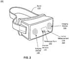
- FIG. 2 is a wire diagram of a virtual reality (VR) headset 200, in accordance with an embodiment.
- the VR headset 200 is an embodiment of the VR headset 105, and includes a front rigid body 205 and a band 210.
- the front rigid body 205 includes one or more electronic display elements of the electronic display 115 (not shown), the IMU 130, the one or more position sensors 125, and the imaging device 135.
- the imaging device 135 is two different cameras, so separated images produced by the two cameras are used to determine distance from the VR headset 200 to a cluster projected by the sparse projection system 136 imaged by both cameras.
- the imaging device 135 is a single camera that includes a range finder for determining distance to a cluster projected by the sparse projection system 136 being imaged.
- one or more imaging devices may be separate from the VR headset 200.
- one or more imaging devices may be configured to view the local area including the VR headset 200 from different vantage points.
- FIG. 3 is an example of illumination of a local area 300 by a sparse projection system 136.
- the local area 300 includes a sparse projector 310 that generates and projects a plurality of clusters 340 throughout the local area 300.
- each cluster has a unique location configuration describing a spatial configuration and a reflectance type of a cluster.
- cluster 340A has a spatial configuration that is different from the spatial configuration of cluster 340B.
- cluster 340A and cluster 340B have a common spatial configuration but different reflectance types.
- capturing an image including a single cluster allows identification of a location of the VR headset 105 within the virtual mapping of the local area 300.
- the local area 300 includes one or more items (chairs, tables, couches, people, etc.).
- the local area 300 includes a table 320 onto which the sparse projector 310 projects certain clusters. The positioning of the table 320 relative to the sparse projector 310 creates a shadow region 330 behind the table 310 where no clusters 340 are projected.
- one or more additional sparse projectors 310 are included in the local area 300 at different locations. For example, including a second sparse projector mounted to the ceiling above the table 320 in the local area 300 of FIG. 3 projects clusters into the shadow region 330, allowing the VR console 110 to generate a better virtual mapping of the local area 300.
- FIG. 4 is a block diagram of an embodiment of a sparse projector 400 including a projection assembly 410.
- the sparse projector 400 includes a source assembly 405 and a projection assembly 410.
- the source assembly 405 is a coherent light source configured to emit a coherent beam of light 412 directed to the projection assembly 410.
- Examples of the source assembly 405 include a laser diode, a vertical cavity surface emitting laser, a tunable laser, or another light source that emits coherent light.
- the source assembly 405 emits light in the IR band; however, in other embodiments, the source assembly 405 emits light in the visible band, in the UV band, or in any other suitable band.
- the beam of light 412 may be relatively collimated.
- the source assembly 405 emits a beam of light 412 that is not collimated.
- the light emitted by the source assembly 405 may be diverging or converging.
- the source assembly 405 also includes a collimator that collimates light from a light source into the beam of light 412.
- the projection assembly 410 receives the beam of light 412 emitted from the source assembly 405 and outputs a plurality of clusters.
- the projection assembly 410 includes a beam expander assembly 420, a diffractive optical element 430, and a transform assembly 440.
- the projection assembly 410 may include different and/or additional components than those described in conjunction with FIG. 4 .
- the beam expander assembly 420 expands the beam of coherent light 412 received from the source assembly 405 to generate an expanded beam of light 422 having dimensions sufficient to fully illuminate the diffractive optical element 430.
- the beam expander assembly 420 may be Galilean, Keplarian, or some other structure configured to generate an expanded beam of light 422 that fully illuminates the diffractive optical element 430 from the beam 412.
- a single diffractive optical element 430 may be deposited on a substrate so the beam of coherent light 412 illuminates just the single diffractive optical element 430.
- the substrate may include multiple diffractive optical elements 430 that each correspond to different sets of clusters, so the beam of coherent light 412 simultaneously illuminates some or all of the multiple diffractive optical elements 430.
- the diffractive optical element 430 is a two-dimensional (2D) Fourier transform of the plurality of clusters for projection into the local area.
- the diffractive optical element 430 is a computer generated hologram generated using computer generated holography, such as Fourier Transform Holography.
- the computer generated hologram is presented on a spatial light modulator (e.g., operating in phase-modulation mode).
- the computer generated hologram is a film applied to an optical element.
- Computer generated holography digitally generates a holographic interference pattern and applies the generated pattern to an optical element, such as the diffractive optical element 430.
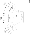
- FIG. 4 includes a representation of an example diffractive optical element 430 that is a 2D Fourier transform of the plurality of clusters.
- a portion 440 of the diffractive optical element 430 is magnified to better illustrate encoding of the diffractive optical element 430.
- the vertical bars shown in the magnified portion 440 of the diffractive optical element 430 are representative of a Fourier transform of a single cluster whose amplitude and phase information have been quantized and encoded onto the portion 440 of the diffractive optical element 430.
- the diffractive optical element 430 attenuates optical power less than a mask, which is an inverse of the desired image in the far field.
- the desired image in the far field is a plurality of clusters including one or more illuminated regions, so a mask for the desired image is transparent in locations corresponding to the illuminated regions and is opaque in other locations.
- FIG. 4 shows a portion of a mask 450 corresponding to a single cluster.
- a mask blocks a significant portion of light, which wastes a large portion of optical power.
- the magnified portion 440 of the diffractive optical element 430 blocks significantly less light than the portion of the mask 450 and also corresponds to a single cluster. Accordingly, using a diffractive optical element 430 reduces the optical power needed to produce clusters 442 relative to use of a mask.
- the transform assembly 440 takes an inverse Fourier transform of light 432 output from the diffractive optical element 430 to generate a plurality of clusters 442, and projects the plurality of clusters 442 into a local area including the sparse projector 400.
- the transform assembly 440 includes a transform lens and a projection component.
- the transform lens is a positive lens that takes a 2D inverse Fourier transform of the output 432 from the diffractive optical element 430 and outputs an image of a plurality of clusters 442 as it would appear in a far field at a back focal plane of the transform lens.
- multiple diffractive optical elements 430 that correspond to different sets of clusters may be illuminated at the same time, so in some instances the transform assembly 440 causes the sets of clusters to be superimposed in the far field.
- the projection component of the transform assembly 440 projects the image of the clusters 442 over a large field of view (e.g., ⁇ a hemisphere) into the local area.
- the projection component includes one or more lenses that are positioned in relation to the image of the clusters 442 to project the clusters 442 over a large field of view.
- a fish eye optic is used so the field of view on which the clusters 442 are projected approaches a hemisphere (e.g., 180 degrees).
- one or more filters and/or baffles may be used to block lower order representations of the image of the clusters 442 from being projected into the local area.
- FIG. 5 is a block diagram of an embodiment of a sparse projector 500 in accordance with the present invention including multiple projection assemblies 510A, 510B, and 510C.
- the sparse projector 500 includes a source assembly 505 and projection assemblies 510A, 510B, and 510C.
- the source assembly 505 is substantially similar to the source assembly 405, which is described above in conjunction with FIG. 4 ; however, the source assembly 505 is configured to output multiple beams of light 515A, 515B, 515C instead of a single beam of light.
- different beams of light 515A, 515B, 515C output by the source assembly 505 are in the same ranges of wavelengths.
- different beams of light 515A, 515B, 515C output by the source assembly 505 are in different ranges of wavelengths.
- the projection assemblies 510A, 510B, and 510C are each substantially similar to the projection assembly 410 described above in conjunction with FIG. 4 .
- each of the projection assemblies 510A, 510B, and 510C include different diffractive optical elements, so each projection assembly 510A, 510B, and 510C outputs a different set of clusters 542A, 542B, and 542C, respectively.
- each cluster within each set of clusters 542A, 542B, and 542C is unique, so a specific cluster appears a single time in the set of clusters 542A, 542B, and 542C.
- the diffractive optical element in each of the projection assemblies 510A, 510B, and 510C is the same, but each projection assembly 510A, 510B, 510C is illuminated using a different range of wavelengths.
- beam of light 515A is a particular range of wavelengths
- beam of light 515B is a different range of wavelengths
- beam of light 515C is another range of wavelengths.
- clusters in different sets of clusters 542A, 542B, and 542C may have the same spatial configuration, but have different reflectance types; thus, each cluster in the sets of clusters 542A, 542B, 542C, still has a unique location configuration.
- multiple projection assemblies 510A, 510B, and 510C allows an increase in the density of clusters in sets of clusters 542A, 542B, and 542C within their respective fields of view of the projection assemblies 510A, 510B, and 510C ( ⁇ 60 degrees each), because a given set of clusters 542A, 542B, and 542C is not spread across the total field of view (e.g., -180 degrees) of the sparse projector 500.
- the projection assembly 410 in FIG. 4 outputs a single set of clusters 442 over the same field of view (e.g., ⁇ 180 degrees). Accordingly, the distance between adjacent clusters in the sets of clusters 542A, 542B, and 542C is smaller, potentially allowing a more accurate virtual mapping of the local area.
- a software module is implemented with a computer program product comprising a computer-readable medium containing computer program code, which can be executed by a computer processor for performing any or all of the steps, operations, or processes described.
- Embodiments of the disclosure may also relate to an apparatus for performing the operations herein.
- This apparatus may be specially constructed for the required purposes, and/or it may comprise a general-purpose computing device selectively activated or reconfigured by a computer program stored in the computer.
- a computer program may be stored in a non-transitory, tangible computer readable storage medium, or any type of media suitable for storing electronic instructions, which may be coupled to a computer system bus.
- any computing systems referred to in the specification may include a single processor or may be architectures employing multiple processor designs for increased computing capability.
- Embodiments of the disclosure may also relate to a product that is produced by a computing process described herein.
- a product may comprise information resulting from a computing process, where the information is stored on a non-transitory, tangible computer readable storage medium and may include any embodiment of a computer program product or other data combination described herein.
Landscapes
- Engineering & Computer Science (AREA)
- Physics & Mathematics (AREA)
- General Physics & Mathematics (AREA)
- Theoretical Computer Science (AREA)
- General Engineering & Computer Science (AREA)
- Optics & Photonics (AREA)
- Human Computer Interaction (AREA)
- Computer Graphics (AREA)
- Computer Hardware Design (AREA)
- Software Systems (AREA)
- User Interface Of Digital Computer (AREA)
- Processing Or Creating Images (AREA)
- Holo Graphy (AREA)
- Image Processing (AREA)
Applications Claiming Priority (2)
| Application Number | Priority Date | Filing Date | Title |
|---|---|---|---|
| US201562128433P | 2015-03-04 | 2015-03-04 | |
| PCT/US2016/020814 WO2016141263A1 (en) | 2015-03-04 | 2016-03-04 | Sparse projection for a virtual reality system |
Publications (3)
| Publication Number | Publication Date |
|---|---|
| EP3114528A1 EP3114528A1 (en) | 2017-01-11 |
| EP3114528A4 EP3114528A4 (en) | 2017-11-01 |
| EP3114528B1 true EP3114528B1 (en) | 2019-11-06 |
Family
ID=56849076
Family Applications (1)
| Application Number | Title | Priority Date | Filing Date |
|---|---|---|---|
| EP16759552.9A Active EP3114528B1 (en) | 2015-03-04 | 2016-03-04 | Sparse projection for a virtual reality system |
Country Status (6)
| Country | Link |
|---|---|
| US (1) | US10073263B2 (cg-RX-API-DMAC7.html) |
| EP (1) | EP3114528B1 (cg-RX-API-DMAC7.html) |
| JP (1) | JP6581203B2 (cg-RX-API-DMAC7.html) |
| KR (1) | KR102054695B1 (cg-RX-API-DMAC7.html) |
| CN (1) | CN107533225B (cg-RX-API-DMAC7.html) |
| WO (1) | WO2016141263A1 (cg-RX-API-DMAC7.html) |
Families Citing this family (17)
| Publication number | Priority date | Publication date | Assignee | Title |
|---|---|---|---|---|
| US10643341B2 (en) | 2018-03-22 | 2020-05-05 | Microsoft Technology Licensing, Llc | Replicated dot maps for simplified depth computation using machine learning |
| US10944957B2 (en) | 2018-03-22 | 2021-03-09 | Microsoft Technology Licensing, Llc | Active stereo matching for depth applications |
| US10728518B2 (en) | 2018-03-22 | 2020-07-28 | Microsoft Technology Licensing, Llc | Movement detection in low light environments |
| US10565720B2 (en) | 2018-03-27 | 2020-02-18 | Microsoft Technology Licensing, Llc | External IR illuminator enabling improved head tracking and surface reconstruction for virtual reality |
| US10994216B2 (en) * | 2019-08-15 | 2021-05-04 | Board Media Group LLC | Virtual reality motion simulator |
| WO2022132828A1 (en) | 2020-12-14 | 2022-06-23 | Summer Robotics, Inc. | Perceiving objects based on sensing surfaces and sensing surface motion |
| WO2023278868A1 (en) | 2021-07-01 | 2023-01-05 | Summer Robotics, Inc. | Calibration of sensor position offsets based on rotation and translation vectors for matched trajectories |
| US12148185B2 (en) | 2021-07-15 | 2024-11-19 | Summer Robotics, Inc. | Automatic parameter adjustment for scanning event cameras |
| US11704835B2 (en) | 2021-07-29 | 2023-07-18 | Summer Robotics, Inc. | Dynamic calibration of 3D acquisition systems |
| CN115728943B (zh) * | 2021-09-02 | 2025-04-01 | 成都极米科技股份有限公司 | Vr投影系统 |
| WO2023177692A1 (en) | 2022-03-14 | 2023-09-21 | Summer Robotics, Inc. | Stage studio for immersive 3-d video capture |
| US20230316657A1 (en) * | 2022-04-05 | 2023-10-05 | Summer Robotics, Inc. | Auxiliary device for augmented reality |
| US12401905B2 (en) | 2022-07-14 | 2025-08-26 | Summer Robotics, Inc. | Foveated robotic vision system |
| US11974055B1 (en) | 2022-10-17 | 2024-04-30 | Summer Robotics, Inc. | Perceiving scene features using event sensors and image sensors |
| US12276730B2 (en) | 2022-11-08 | 2025-04-15 | Summer Robotics, Inc. | Virtual fences in air, water, and space |
| US12416804B1 (en) | 2024-05-08 | 2025-09-16 | Summer Robotics, Inc. | Kaleidoscopic laser beam projection system |
| CN120812235B (zh) * | 2025-09-09 | 2025-11-11 | 南京芯视元电子有限公司 | 微显示系统及头显设备 |
Family Cites Families (17)
| Publication number | Priority date | Publication date | Assignee | Title |
|---|---|---|---|---|
| JP4473133B2 (ja) * | 2002-11-13 | 2010-06-02 | シーリアル、テクノロジーズ、ゲーエムベーハー | 映像ホログラムおよび映像ホログラム再生装置 |
| EP1897010A1 (en) * | 2005-06-30 | 2008-03-12 | Nokia Corporation | Camera control means to allow operating of a destined location of the information surface of a presentation and information system |
| JP5796578B2 (ja) * | 2010-09-08 | 2015-10-21 | 大日本印刷株式会社 | 投射装置および投射型映像表示装置 |
| WO2012049795A1 (ja) * | 2010-10-12 | 2012-04-19 | パナソニック株式会社 | 表示処理装置、表示方法およびプログラム |
| US20140063061A1 (en) * | 2011-08-26 | 2014-03-06 | Reincloud Corporation | Determining a position of an item in a virtual augmented space |
| JP5966510B2 (ja) * | 2012-03-29 | 2016-08-10 | ソニー株式会社 | 情報処理システム |
| KR101861380B1 (ko) * | 2012-07-16 | 2018-05-28 | 마이크로소프트 테크놀로지 라이센싱, 엘엘씨 | 헤드 마운트 디스플레이를 이용한 컨텐츠 출력 방법 및 이를 위한 헤드 마운트 디스플레이 |
| US8711370B1 (en) | 2012-10-04 | 2014-04-29 | Gerard Dirk Smits | Scanning optical positioning system with spatially triangulating receivers |
| JP6061334B2 (ja) | 2012-11-26 | 2017-01-18 | Kddi株式会社 | 光学式シースルー型hmdを用いたarシステム |
| US20140160162A1 (en) * | 2012-12-12 | 2014-06-12 | Dhanushan Balachandreswaran | Surface projection device for augmented reality |
| JP6123342B2 (ja) * | 2013-02-20 | 2017-05-10 | ソニー株式会社 | 表示装置 |
| EP2797313A1 (en) | 2013-04-26 | 2014-10-29 | Elvesjö, John | Computer graphics presentation system and method |
| DE102013210746A1 (de) * | 2013-06-10 | 2014-12-11 | Robert Bosch Gmbh | System und Verfahren zum Überwachen und/oder Bedienen einer technischen Anlage, insbesondere eines Fahrzeugs |
| CN103617636B (zh) * | 2013-12-02 | 2016-08-17 | 西北工业大学 | 基于运动信息及稀疏投影的视频目标自动检测跟踪方法 |
| KR20150096948A (ko) | 2014-02-17 | 2015-08-26 | 엘지전자 주식회사 | 증강 현실 사진 촬영 가이드를 디스플레이 하는 헤드 마운티드 디스플레이 디바이스 및 그 제어 방법 |
| WO2015138266A1 (en) * | 2014-03-10 | 2015-09-17 | Ion Virtual Technology Corporation | Modular and convertible virtual reality headset system |
| CN110308561A (zh) * | 2014-03-14 | 2019-10-08 | 索尼互动娱乐股份有限公司 | 用于头戴式显示器(hmd)的方法和系统 |
-
2016
- 2016-03-04 JP JP2017546086A patent/JP6581203B2/ja active Active
- 2016-03-04 US US15/060,686 patent/US10073263B2/en active Active
- 2016-03-04 KR KR1020177026280A patent/KR102054695B1/ko not_active Expired - Fee Related
- 2016-03-04 CN CN201680022460.1A patent/CN107533225B/zh active Active
- 2016-03-04 WO PCT/US2016/020814 patent/WO2016141263A1/en not_active Ceased
- 2016-03-04 EP EP16759552.9A patent/EP3114528B1/en active Active
Non-Patent Citations (1)
| Title |
|---|
| None * |
Also Published As
| Publication number | Publication date |
|---|---|
| EP3114528A4 (en) | 2017-11-01 |
| JP6581203B2 (ja) | 2019-09-25 |
| EP3114528A1 (en) | 2017-01-11 |
| WO2016141263A1 (en) | 2016-09-09 |
| CN107533225A (zh) | 2018-01-02 |
| KR102054695B1 (ko) | 2019-12-11 |
| JP2018517187A (ja) | 2018-06-28 |
| KR20170122215A (ko) | 2017-11-03 |
| CN107533225B (zh) | 2020-07-14 |
| US20160259168A1 (en) | 2016-09-08 |
| US10073263B2 (en) | 2018-09-11 |
Similar Documents
| Publication | Publication Date | Title |
|---|---|---|
| EP3114528B1 (en) | Sparse projection for a virtual reality system | |
| US10529113B1 (en) | Generating graphical representation of facial expressions of a user wearing a head mounted display accounting for previously captured images of the user's facial expressions | |
| US10469722B2 (en) | Spatially tiled structured light projector | |
| JP7307093B2 (ja) | 深度検知システム用の動的構造化光 | |
| US10636193B1 (en) | Generating graphical representation of a user's face and body using a monitoring system included on a head mounted display | |
| CN109565585B (zh) | 用于深度信息确定的多发射器照明源 | |
| US10410373B1 (en) | Calibration of a phase interferometry depth camera assembly | |
| US10013055B2 (en) | Eye tracking using optical flow | |
| US10120442B2 (en) | Eye tracking using a light field camera on a head-mounted display | |
| US11102467B2 (en) | Array detector for depth mapping | |
| US10684674B2 (en) | Tracking portions of a user's face uncovered by a head mounted display worn by the user | |
| US11348262B1 (en) | Three-dimensional imaging with spatial and temporal coding for depth camera assembly | |
| JP6377863B2 (ja) | 反射マップ表現による奥行きマップ表現の増補 | |
| US10948283B1 (en) | Tileable structured light projection system | |
| US10795436B2 (en) | Determining fixation of a user's eyes from images of portions of the user's face enclosed by a head mounted display | |
| US10789777B1 (en) | Generating content for presentation by a head mounted display based on data captured by a light field camera positioned on the head mounted display | |
| US10521926B1 (en) | Tileable non-planar structured light patterns for wide field-of-view depth sensing | |
| US10462451B1 (en) | Asymmetric structured light source | |
| US10855973B1 (en) | Depth mapping using fringe interferometry | |
| EP3282285B1 (en) | Multiple emitter illumination source for depth information determination | |
| US10495882B1 (en) | Positioning cameras in a head mounted display to capture images of portions of a face of a user | |
| US10586343B1 (en) | 3-d head mounted display based environmental modeling system | |
| US10852434B1 (en) | Depth camera assembly using fringe interferometery via multiple wavelengths |
Legal Events
| Date | Code | Title | Description |
|---|---|---|---|
| STAA | Information on the status of an ep patent application or granted ep patent |
Free format text: STATUS: THE INTERNATIONAL PUBLICATION HAS BEEN MADE |
|
| PUAI | Public reference made under article 153(3) epc to a published international application that has entered the european phase |
Free format text: ORIGINAL CODE: 0009012 |
|
| STAA | Information on the status of an ep patent application or granted ep patent |
Free format text: STATUS: REQUEST FOR EXAMINATION WAS MADE |
|
| 17P | Request for examination filed |
Effective date: 20161006 |
|
| AK | Designated contracting states |
Kind code of ref document: A1 Designated state(s): AL AT BE BG CH CY CZ DE DK EE ES FI FR GB GR HR HU IE IS IT LI LT LU LV MC MK MT NL NO PL PT RO RS SE SI SK SM TR |
|
| AX | Request for extension of the european patent |
Extension state: BA ME |
|
| REG | Reference to a national code |
Ref country code: DE Ref legal event code: R079 Ref document number: 602016023845 Country of ref document: DE Free format text: PREVIOUS MAIN CLASS: G02B0027220000 Ipc: G06F0003010000 |
|
| A4 | Supplementary search report drawn up and despatched |
Effective date: 20170929 |
|
| RIC1 | Information provided on ipc code assigned before grant |
Ipc: G06F 3/01 20060101AFI20170925BHEP Ipc: G03B 21/14 20060101ALI20170925BHEP Ipc: G02B 27/01 20060101ALI20170925BHEP |
|
| DAV | Request for validation of the european patent (deleted) | ||
| DAX | Request for extension of the european patent (deleted) | ||
| RAP1 | Party data changed (applicant data changed or rights of an application transferred) |
Owner name: FACEBOOK TECHNOLOGIES, LLC |
|
| GRAP | Despatch of communication of intention to grant a patent |
Free format text: ORIGINAL CODE: EPIDOSNIGR1 |
|
| STAA | Information on the status of an ep patent application or granted ep patent |
Free format text: STATUS: GRANT OF PATENT IS INTENDED |
|
| INTG | Intention to grant announced |
Effective date: 20190604 |
|
| GRAS | Grant fee paid |
Free format text: ORIGINAL CODE: EPIDOSNIGR3 |
|
| GRAA | (expected) grant |
Free format text: ORIGINAL CODE: 0009210 |
|
| STAA | Information on the status of an ep patent application or granted ep patent |
Free format text: STATUS: THE PATENT HAS BEEN GRANTED |
|
| AK | Designated contracting states |
Kind code of ref document: B1 Designated state(s): AL AT BE BG CH CY CZ DE DK EE ES FI FR GB GR HR HU IE IS IT LI LT LU LV MC MK MT NL NO PL PT RO RS SE SI SK SM TR |
|
| REG | Reference to a national code |
Ref country code: GB Ref legal event code: FG4D |
|
| REG | Reference to a national code |
Ref country code: CH Ref legal event code: EP Ref country code: AT Ref legal event code: REF Ref document number: 1199649 Country of ref document: AT Kind code of ref document: T Effective date: 20191115 |
|
| REG | Reference to a national code |
Ref country code: IE Ref legal event code: FG4D |
|
| REG | Reference to a national code |
Ref country code: DE Ref legal event code: R096 Ref document number: 602016023845 Country of ref document: DE |
|
| REG | Reference to a national code |
Ref country code: NL Ref legal event code: MP Effective date: 20191106 |
|
| REG | Reference to a national code |
Ref country code: LT Ref legal event code: MG4D |
|
| PG25 | Lapsed in a contracting state [announced via postgrant information from national office to epo] |
Ref country code: BG Free format text: LAPSE BECAUSE OF FAILURE TO SUBMIT A TRANSLATION OF THE DESCRIPTION OR TO PAY THE FEE WITHIN THE PRESCRIBED TIME-LIMIT Effective date: 20200206 Ref country code: NO Free format text: LAPSE BECAUSE OF FAILURE TO SUBMIT A TRANSLATION OF THE DESCRIPTION OR TO PAY THE FEE WITHIN THE PRESCRIBED TIME-LIMIT Effective date: 20200206 Ref country code: FI Free format text: LAPSE BECAUSE OF FAILURE TO SUBMIT A TRANSLATION OF THE DESCRIPTION OR TO PAY THE FEE WITHIN THE PRESCRIBED TIME-LIMIT Effective date: 20191106 Ref country code: LT Free format text: LAPSE BECAUSE OF FAILURE TO SUBMIT A TRANSLATION OF THE DESCRIPTION OR TO PAY THE FEE WITHIN THE PRESCRIBED TIME-LIMIT Effective date: 20191106 Ref country code: PT Free format text: LAPSE BECAUSE OF FAILURE TO SUBMIT A TRANSLATION OF THE DESCRIPTION OR TO PAY THE FEE WITHIN THE PRESCRIBED TIME-LIMIT Effective date: 20200306 Ref country code: LV Free format text: LAPSE BECAUSE OF FAILURE TO SUBMIT A TRANSLATION OF THE DESCRIPTION OR TO PAY THE FEE WITHIN THE PRESCRIBED TIME-LIMIT Effective date: 20191106 Ref country code: SE Free format text: LAPSE BECAUSE OF FAILURE TO SUBMIT A TRANSLATION OF THE DESCRIPTION OR TO PAY THE FEE WITHIN THE PRESCRIBED TIME-LIMIT Effective date: 20191106 Ref country code: NL Free format text: LAPSE BECAUSE OF FAILURE TO SUBMIT A TRANSLATION OF THE DESCRIPTION OR TO PAY THE FEE WITHIN THE PRESCRIBED TIME-LIMIT Effective date: 20191106 Ref country code: PL Free format text: LAPSE BECAUSE OF FAILURE TO SUBMIT A TRANSLATION OF THE DESCRIPTION OR TO PAY THE FEE WITHIN THE PRESCRIBED TIME-LIMIT Effective date: 20191106 Ref country code: GR Free format text: LAPSE BECAUSE OF FAILURE TO SUBMIT A TRANSLATION OF THE DESCRIPTION OR TO PAY THE FEE WITHIN THE PRESCRIBED TIME-LIMIT Effective date: 20200207 |
|
| PG25 | Lapsed in a contracting state [announced via postgrant information from national office to epo] |
Ref country code: IS Free format text: LAPSE BECAUSE OF FAILURE TO SUBMIT A TRANSLATION OF THE DESCRIPTION OR TO PAY THE FEE WITHIN THE PRESCRIBED TIME-LIMIT Effective date: 20200306 Ref country code: HR Free format text: LAPSE BECAUSE OF FAILURE TO SUBMIT A TRANSLATION OF THE DESCRIPTION OR TO PAY THE FEE WITHIN THE PRESCRIBED TIME-LIMIT Effective date: 20191106 Ref country code: RS Free format text: LAPSE BECAUSE OF FAILURE TO SUBMIT A TRANSLATION OF THE DESCRIPTION OR TO PAY THE FEE WITHIN THE PRESCRIBED TIME-LIMIT Effective date: 20191106 |
|
| PG25 | Lapsed in a contracting state [announced via postgrant information from national office to epo] |
Ref country code: AL Free format text: LAPSE BECAUSE OF FAILURE TO SUBMIT A TRANSLATION OF THE DESCRIPTION OR TO PAY THE FEE WITHIN THE PRESCRIBED TIME-LIMIT Effective date: 20191106 |
|
| PG25 | Lapsed in a contracting state [announced via postgrant information from national office to epo] |
Ref country code: CZ Free format text: LAPSE BECAUSE OF FAILURE TO SUBMIT A TRANSLATION OF THE DESCRIPTION OR TO PAY THE FEE WITHIN THE PRESCRIBED TIME-LIMIT Effective date: 20191106 Ref country code: ES Free format text: LAPSE BECAUSE OF FAILURE TO SUBMIT A TRANSLATION OF THE DESCRIPTION OR TO PAY THE FEE WITHIN THE PRESCRIBED TIME-LIMIT Effective date: 20191106 Ref country code: RO Free format text: LAPSE BECAUSE OF FAILURE TO SUBMIT A TRANSLATION OF THE DESCRIPTION OR TO PAY THE FEE WITHIN THE PRESCRIBED TIME-LIMIT Effective date: 20191106 Ref country code: EE Free format text: LAPSE BECAUSE OF FAILURE TO SUBMIT A TRANSLATION OF THE DESCRIPTION OR TO PAY THE FEE WITHIN THE PRESCRIBED TIME-LIMIT Effective date: 20191106 Ref country code: DK Free format text: LAPSE BECAUSE OF FAILURE TO SUBMIT A TRANSLATION OF THE DESCRIPTION OR TO PAY THE FEE WITHIN THE PRESCRIBED TIME-LIMIT Effective date: 20191106 |
|
| REG | Reference to a national code |
Ref country code: DE Ref legal event code: R097 Ref document number: 602016023845 Country of ref document: DE |
|
| REG | Reference to a national code |
Ref country code: AT Ref legal event code: MK05 Ref document number: 1199649 Country of ref document: AT Kind code of ref document: T Effective date: 20191106 |
|
| PG25 | Lapsed in a contracting state [announced via postgrant information from national office to epo] |
Ref country code: SM Free format text: LAPSE BECAUSE OF FAILURE TO SUBMIT A TRANSLATION OF THE DESCRIPTION OR TO PAY THE FEE WITHIN THE PRESCRIBED TIME-LIMIT Effective date: 20191106 Ref country code: SK Free format text: LAPSE BECAUSE OF FAILURE TO SUBMIT A TRANSLATION OF THE DESCRIPTION OR TO PAY THE FEE WITHIN THE PRESCRIBED TIME-LIMIT Effective date: 20191106 |
|
| PLBE | No opposition filed within time limit |
Free format text: ORIGINAL CODE: 0009261 |
|
| STAA | Information on the status of an ep patent application or granted ep patent |
Free format text: STATUS: NO OPPOSITION FILED WITHIN TIME LIMIT |
|
| 26N | No opposition filed |
Effective date: 20200807 |
|
| PG25 | Lapsed in a contracting state [announced via postgrant information from national office to epo] |
Ref country code: MC Free format text: LAPSE BECAUSE OF FAILURE TO SUBMIT A TRANSLATION OF THE DESCRIPTION OR TO PAY THE FEE WITHIN THE PRESCRIBED TIME-LIMIT Effective date: 20191106 |
|
| REG | Reference to a national code |
Ref country code: CH Ref legal event code: PL |
|
| PG25 | Lapsed in a contracting state [announced via postgrant information from national office to epo] |
Ref country code: AT Free format text: LAPSE BECAUSE OF FAILURE TO SUBMIT A TRANSLATION OF THE DESCRIPTION OR TO PAY THE FEE WITHIN THE PRESCRIBED TIME-LIMIT Effective date: 20191106 Ref country code: SI Free format text: LAPSE BECAUSE OF FAILURE TO SUBMIT A TRANSLATION OF THE DESCRIPTION OR TO PAY THE FEE WITHIN THE PRESCRIBED TIME-LIMIT Effective date: 20191106 |
|
| REG | Reference to a national code |
Ref country code: BE Ref legal event code: MM Effective date: 20200331 |
|
| PG25 | Lapsed in a contracting state [announced via postgrant information from national office to epo] |
Ref country code: LU Free format text: LAPSE BECAUSE OF NON-PAYMENT OF DUE FEES Effective date: 20200304 |
|
| PG25 | Lapsed in a contracting state [announced via postgrant information from national office to epo] |
Ref country code: IT Free format text: LAPSE BECAUSE OF FAILURE TO SUBMIT A TRANSLATION OF THE DESCRIPTION OR TO PAY THE FEE WITHIN THE PRESCRIBED TIME-LIMIT Effective date: 20191106 Ref country code: CH Free format text: LAPSE BECAUSE OF NON-PAYMENT OF DUE FEES Effective date: 20200331 Ref country code: FR Free format text: LAPSE BECAUSE OF NON-PAYMENT OF DUE FEES Effective date: 20200331 Ref country code: LI Free format text: LAPSE BECAUSE OF NON-PAYMENT OF DUE FEES Effective date: 20200331 Ref country code: IE Free format text: LAPSE BECAUSE OF NON-PAYMENT OF DUE FEES Effective date: 20200304 |
|
| PG25 | Lapsed in a contracting state [announced via postgrant information from national office to epo] |
Ref country code: BE Free format text: LAPSE BECAUSE OF NON-PAYMENT OF DUE FEES Effective date: 20200331 |
|
| PG25 | Lapsed in a contracting state [announced via postgrant information from national office to epo] |
Ref country code: TR Free format text: LAPSE BECAUSE OF FAILURE TO SUBMIT A TRANSLATION OF THE DESCRIPTION OR TO PAY THE FEE WITHIN THE PRESCRIBED TIME-LIMIT Effective date: 20191106 Ref country code: MT Free format text: LAPSE BECAUSE OF FAILURE TO SUBMIT A TRANSLATION OF THE DESCRIPTION OR TO PAY THE FEE WITHIN THE PRESCRIBED TIME-LIMIT Effective date: 20191106 Ref country code: CY Free format text: LAPSE BECAUSE OF FAILURE TO SUBMIT A TRANSLATION OF THE DESCRIPTION OR TO PAY THE FEE WITHIN THE PRESCRIBED TIME-LIMIT Effective date: 20191106 |
|
| PG25 | Lapsed in a contracting state [announced via postgrant information from national office to epo] |
Ref country code: MK Free format text: LAPSE BECAUSE OF FAILURE TO SUBMIT A TRANSLATION OF THE DESCRIPTION OR TO PAY THE FEE WITHIN THE PRESCRIBED TIME-LIMIT Effective date: 20191106 |
|
| P01 | Opt-out of the competence of the unified patent court (upc) registered |
Effective date: 20230525 |
|
| REG | Reference to a national code |
Ref country code: DE Ref legal event code: R081 Ref document number: 602016023845 Country of ref document: DE Owner name: META PLATFORMS TECHNOLOGIES, LLC, MENLO PARK, US Free format text: FORMER OWNER: FACEBOOK TECHNOLOGIES, LLC, MENLO PARK, CALIF., US |
|
| PGFP | Annual fee paid to national office [announced via postgrant information from national office to epo] |
Ref country code: GB Payment date: 20250331 Year of fee payment: 10 |
|
| PGFP | Annual fee paid to national office [announced via postgrant information from national office to epo] |
Ref country code: DE Payment date: 20250331 Year of fee payment: 10 |