EP3114293B1 - Support structure for a fence - Google Patents
Support structure for a fence Download PDFInfo
- Publication number
- EP3114293B1 EP3114293B1 EP15717622.3A EP15717622A EP3114293B1 EP 3114293 B1 EP3114293 B1 EP 3114293B1 EP 15717622 A EP15717622 A EP 15717622A EP 3114293 B1 EP3114293 B1 EP 3114293B1
- Authority
- EP
- European Patent Office
- Prior art keywords
- post
- base
- horizontal
- respect
- engagement
- Prior art date
- Legal status (The legal status is an assumption and is not a legal conclusion. Google has not performed a legal analysis and makes no representation as to the accuracy of the status listed.)
- Active
Links
Images

Classifications
-
- E—FIXED CONSTRUCTIONS
- E04—BUILDING
- E04H—BUILDINGS OR LIKE STRUCTURES FOR PARTICULAR PURPOSES; SWIMMING OR SPLASH BATHS OR POOLS; MASTS; FENCING; TENTS OR CANOPIES, IN GENERAL
- E04H12/00—Towers; Masts or poles; Chimney stacks; Water-towers; Methods of erecting such structures
- E04H12/22—Sockets or holders for poles or posts
- E04H12/2292—Holders used for protection, repair or reinforcement of the post or pole
-
- A—HUMAN NECESSITIES
- A63—SPORTS; GAMES; AMUSEMENTS
- A63B—APPARATUS FOR PHYSICAL TRAINING, GYMNASTICS, SWIMMING, CLIMBING, OR FENCING; BALL GAMES; TRAINING EQUIPMENT
- A63B71/00—Games or sports accessories not covered in groups A63B1/00 - A63B69/00
- A63B71/02—Games or sports accessories not covered in groups A63B1/00 - A63B69/00 for large-room or outdoor sporting games
- A63B71/022—Backstops, cages, enclosures or the like, e.g. for spectator protection, for arresting balls
-
- A—HUMAN NECESSITIES
- A63—SPORTS; GAMES; AMUSEMENTS
- A63B—APPARATUS FOR PHYSICAL TRAINING, GYMNASTICS, SWIMMING, CLIMBING, OR FENCING; BALL GAMES; TRAINING EQUIPMENT
- A63B71/00—Games or sports accessories not covered in groups A63B1/00 - A63B69/00
- A63B71/02—Games or sports accessories not covered in groups A63B1/00 - A63B69/00 for large-room or outdoor sporting games
- A63B71/023—Supports, e.g. poles
-
- E—FIXED CONSTRUCTIONS
- E01—CONSTRUCTION OF ROADS, RAILWAYS, OR BRIDGES
- E01F—ADDITIONAL WORK, SUCH AS EQUIPPING ROADS OR THE CONSTRUCTION OF PLATFORMS, HELICOPTER LANDING STAGES, SIGNS, SNOW FENCES, OR THE LIKE
- E01F13/00—Arrangements for obstructing or restricting traffic, e.g. gates, barricades ; Preventing passage of vehicles of selected category or dimensions
- E01F13/02—Arrangements for obstructing or restricting traffic, e.g. gates, barricades ; Preventing passage of vehicles of selected category or dimensions free-standing; portable, e.g. for guarding open manholes ; Portable signs or signals specially adapted for fitting to portable barriers
-
- E—FIXED CONSTRUCTIONS
- E01—CONSTRUCTION OF ROADS, RAILWAYS, OR BRIDGES
- E01F—ADDITIONAL WORK, SUCH AS EQUIPPING ROADS OR THE CONSTRUCTION OF PLATFORMS, HELICOPTER LANDING STAGES, SIGNS, SNOW FENCES, OR THE LIKE
- E01F9/00—Arrangement of road signs or traffic signals; Arrangements for enforcing caution
- E01F9/60—Upright bodies, e.g. marker posts or bollards; Supports for road signs
- E01F9/623—Upright bodies, e.g. marker posts or bollards; Supports for road signs characterised by form or by structural features, e.g. for enabling displacement or deflection
- E01F9/631—Upright bodies, e.g. marker posts or bollards; Supports for road signs characterised by form or by structural features, e.g. for enabling displacement or deflection specially adapted for breaking, disengaging, collapsing or permanently deforming when deflected or displaced, e.g. by vehicle impact
- E01F9/638—Upright bodies, e.g. marker posts or bollards; Supports for road signs characterised by form or by structural features, e.g. for enabling displacement or deflection specially adapted for breaking, disengaging, collapsing or permanently deforming when deflected or displaced, e.g. by vehicle impact by connection of stud-and-socket type, e.g. spring-loaded
-
- E—FIXED CONSTRUCTIONS
- E04—BUILDING
- E04H—BUILDINGS OR LIKE STRUCTURES FOR PARTICULAR PURPOSES; SWIMMING OR SPLASH BATHS OR POOLS; MASTS; FENCING; TENTS OR CANOPIES, IN GENERAL
- E04H12/00—Towers; Masts or poles; Chimney stacks; Water-towers; Methods of erecting such structures
- E04H12/22—Sockets or holders for poles or posts
- E04H12/2253—Mounting poles or posts to the holder
-
- E—FIXED CONSTRUCTIONS
- E04—BUILDING
- E04H—BUILDINGS OR LIKE STRUCTURES FOR PARTICULAR PURPOSES; SWIMMING OR SPLASH BATHS OR POOLS; MASTS; FENCING; TENTS OR CANOPIES, IN GENERAL
- E04H12/00—Towers; Masts or poles; Chimney stacks; Water-towers; Methods of erecting such structures
- E04H12/22—Sockets or holders for poles or posts
- E04H12/2253—Mounting poles or posts to the holder
- E04H12/2261—Mounting poles or posts to the holder on a flat base
-
- E—FIXED CONSTRUCTIONS
- E04—BUILDING
- E04H—BUILDINGS OR LIKE STRUCTURES FOR PARTICULAR PURPOSES; SWIMMING OR SPLASH BATHS OR POOLS; MASTS; FENCING; TENTS OR CANOPIES, IN GENERAL
- E04H12/00—Towers; Masts or poles; Chimney stacks; Water-towers; Methods of erecting such structures
- E04H12/22—Sockets or holders for poles or posts
- E04H12/2253—Mounting poles or posts to the holder
- E04H12/2269—Mounting poles or posts to the holder in a socket
-
- E—FIXED CONSTRUCTIONS
- E04—BUILDING
- E04H—BUILDINGS OR LIKE STRUCTURES FOR PARTICULAR PURPOSES; SWIMMING OR SPLASH BATHS OR POOLS; MASTS; FENCING; TENTS OR CANOPIES, IN GENERAL
- E04H12/00—Towers; Masts or poles; Chimney stacks; Water-towers; Methods of erecting such structures
- E04H12/22—Sockets or holders for poles or posts
- E04H12/2284—Means for adjusting the orientation of the post or pole
-
- E—FIXED CONSTRUCTIONS
- E04—BUILDING
- E04H—BUILDINGS OR LIKE STRUCTURES FOR PARTICULAR PURPOSES; SWIMMING OR SPLASH BATHS OR POOLS; MASTS; FENCING; TENTS OR CANOPIES, IN GENERAL
- E04H17/00—Fencing, e.g. fences, enclosures, corrals
- E04H17/009—Footing elements for fence posts or fence sections
-
- F—MECHANICAL ENGINEERING; LIGHTING; HEATING; WEAPONS; BLASTING
- F16—ENGINEERING ELEMENTS AND UNITS; GENERAL MEASURES FOR PRODUCING AND MAINTAINING EFFECTIVE FUNCTIONING OF MACHINES OR INSTALLATIONS; THERMAL INSULATION IN GENERAL
- F16M—FRAMES, CASINGS OR BEDS OF ENGINES, MACHINES OR APPARATUS, NOT SPECIFIC TO ENGINES, MACHINES OR APPARATUS PROVIDED FOR ELSEWHERE; STANDS; SUPPORTS
- F16M11/00—Stands or trestles as supports for apparatus or articles placed thereon ; Stands for scientific apparatus such as gravitational force meters
- F16M11/02—Heads
- F16M11/04—Means for attachment of apparatus; Means allowing adjustment of the apparatus relatively to the stand
- F16M11/06—Means for attachment of apparatus; Means allowing adjustment of the apparatus relatively to the stand allowing pivoting
- F16M11/10—Means for attachment of apparatus; Means allowing adjustment of the apparatus relatively to the stand allowing pivoting around a horizontal axis
-
- F—MECHANICAL ENGINEERING; LIGHTING; HEATING; WEAPONS; BLASTING
- F16—ENGINEERING ELEMENTS AND UNITS; GENERAL MEASURES FOR PRODUCING AND MAINTAINING EFFECTIVE FUNCTIONING OF MACHINES OR INSTALLATIONS; THERMAL INSULATION IN GENERAL
- F16M—FRAMES, CASINGS OR BEDS OF ENGINES, MACHINES OR APPARATUS, NOT SPECIFIC TO ENGINES, MACHINES OR APPARATUS PROVIDED FOR ELSEWHERE; STANDS; SUPPORTS
- F16M11/00—Stands or trestles as supports for apparatus or articles placed thereon ; Stands for scientific apparatus such as gravitational force meters
- F16M11/02—Heads
- F16M11/16—Details concerning attachment of head-supporting legs, with or without actuation of locking members thereof
Definitions
- the present invention generically relates to the sector of fencing posts, and in particular to fencing posts for sports facilities.
- the fence In most cases sports facilities are surrounded by a fence aimed at limiting the sport activity area and avoiding the intrusion of unauthorised users.
- the fence consists of a series of posts arranged at regular distances apt to support a protection mesh.
- FR1482473 discloses a tripartite post, wherein the intermediate element is made of rubber, to guarantee the oscillation of the element connected thereto above.
- the oscillation be exclusively one-directional, and specifically from the inside to the outside of the activity area. The need is therefore felt to accomplish a fencing post which is able to undergo a temporary deformation seconding the impact force according to a single direction.
- the object of the present invention is therefore to accomplish a fencing post which is capable of seconding along a single motion direction the impact due to a moving body, contextually reducing the traumatic effect due to the impact, without any deformation from outside the fencing being possible.
- the supporting structure consisting of a base made up of a bottom plate from which a box body projects open on one side which houses and supports a fencing post, characterised in that in said structure horizontal and rotational displacement means of said post with respect to said base are provided as well as adjustment means of the horizontal sliding motion and rotation means of said post with respect to said base.
- said horizontal displacement and rotation means consist of hinging means passing through horizontal eyelets provided on the lateral parallel walls of the box body and kept in engagement with said post.
- the adjustment means of the horizontal and rotation motion consist of horizontal and vertical spring means, kept in steady engagement with said base and said post, respectively.
- said base plate is provided with a circular cavity 12 apt to the housing of said spring 11.
- Such structure allows a controlled and one-directional, rotary and translational movement - possibly combined.
- the lateral walls 3a, 3b of box body 3 define the rotation direction of post 4, while the relationship between through-screw 5 and eyelets 6 guides the horizontal displacement thereof.
- the maximum angle of rotation of post 4 with respect to the hinging axis passing through screw 5 is defined by the distance between post 4 and the top wall 3d of box body 3.
- a fencing support system has been obtained provided with a base carrying hinging means for post bending and opposition and return means of the post displacement. Therefore, rigidly fastening the base to an outside support, such as for example a plinth or curb made of reinforced concrete, one nevertheless has the guarantee of the bending with respect to a vertical axis in a defined direction whenever an outside force is applied to return in the initial position. With respect to other existing solutions, the assurance of controlled return by a dampening system apt to avoid the return recoil was desired.
Landscapes
- Engineering & Computer Science (AREA)
- Architecture (AREA)
- Civil Engineering (AREA)
- Structural Engineering (AREA)
- General Engineering & Computer Science (AREA)
- Mechanical Engineering (AREA)
- Health & Medical Sciences (AREA)
- General Health & Medical Sciences (AREA)
- Physical Education & Sports Medicine (AREA)
- Fencing (AREA)
- Pit Excavations, Shoring, Fill Or Stabilisation Of Slopes (AREA)
Description
- The present invention generically relates to the sector of fencing posts, and in particular to fencing posts for sports facilities.
- In most cases sports facilities are surrounded by a fence aimed at limiting the sport activity area and avoiding the intrusion of unauthorised users. Typically, the fence consists of a series of posts arranged at regular distances apt to support a protection mesh.
- The rigidity of the posts conventionally used in the building industry in certain cases has been a cause of traumas due - during operation - to an athlete's direct and involuntary impact against one of the posts. Understandably, this kind of problem has occurred, and has remarkable importance, especially in those plants where children are present, both due to their greater fragility, and to the lesser motor ability in agonistic activity.
- In order to improve safety, and reduce accidents, posts provided with resilient properties have been manufactured, that is, posts provided with means apt to guarantee a controlled deformation limited in the vertical plane with a defined degree of rigidity, and to allow the independent return thereof into the original position.
- In the past various devices have been used. For example,
FR1482473 - However, this kind of post - due to the very nature of the material it is made of - cannot guarantee any certainty on the oscillation direction, with the consequent risk that the effect of a similar solution is counterproductive. As a matter of fact, since no protection system from (desired or undesired) outside stresses can be expected, the risk that athletes are victims of an unexpected and undesired oscillation of one or more fence posts leads to look for alternative solutions.
- In particular, for the post to be able to guarantee the required safety, it is necessary that the oscillation be exclusively one-directional, and specifically from the inside to the outside of the activity area. The need is therefore felt to accomplish a fencing post which is able to undergo a temporary deformation seconding the impact force according to a single direction.
- Moreover, it has been detected that the prior-art posts apt to reduce the impact effect have the further disadvantage of having a limited effect in the impact absorption.
- Further known supporting structures for fences are described in
US 4 137 662 A ,GB 2 489 228 AUS 2005/173690 A1 . - It is thus felt the further need to find solutions which may reduce the impact effect, increasing instead the motion amount absorbed by the impact.
- The object of the present invention is therefore to accomplish a fencing post which is capable of seconding along a single motion direction the impact due to a moving body, contextually reducing the traumatic effect due to the impact, without any deformation from outside the fencing being possible.
- Said object is achieved through a supporting structure according to appended
claim 1. The supporting structure consisting of a base made up of a bottom plate from which a box body projects open on one side which houses and supports a fencing post, characterised in that in said structure horizontal and rotational displacement means of said post with respect to said base are provided as well as adjustment means of the horizontal sliding motion and rotation means of said post with respect to said base. - In particular, said horizontal displacement and rotation means consist of hinging means passing through horizontal eyelets provided on the lateral parallel walls of the box body and kept in engagement with said post. Equally, the adjustment means of the horizontal and rotation motion consist of horizontal and vertical spring means, kept in steady engagement with said base and said post, respectively.
- Other features and advantages of the solution just briefly described will be clearer from the following description of the invention with reference to a preferred embodiment, given purely as a non-limiting example and illustrated in the attached drawings, wherein:
-
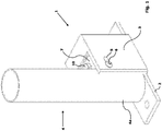
fig. 1 represents a perspective view from above of the structure according to the invention; -
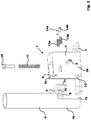
fig. 2 is the exploded view of the structure offig. 1 , -
fig. 3 is the front view of the structure offig. 1 , and -
fig. 4 is the section view along the lines A-A of the structure offig. 2 . - The support structure of a fence consists of a
base 1 consisting of abase plate 2 from which abox body 3 open on one side and partly on the top surface projects, which houses within thetapered base 4a of apost 4 projecting upwards, kept in engagement with saidbox body 3 by a through-screw 5 for hingingpost 4 tobase 1. For such purpose,screw 5 enters horizontal eyelets 6 obtained on the walls of the two opposite sides (3a, 3b) of said box body. - In the illustrated embodiment,
post 4 has a substantially circular shape, with the exclusion ofbase 4a, which has a semicircular shape, on the planar walls, that is, the vertical one of thesemicircular portion 4a, and the one perpendicular thereto from which the circular portion originates, a J-shaped bracket 7 being welded. - In correspondence of the angle between the greatest-
length surface 7a and thesurface 7b adjacent thereto, and parallel to the ground, it is furthermore welded abush 8 apt to house said through-screw 5. Finally, centrally to thesurface 7b parallel to the ground a through-hole 9 is provided 9 for the housing of a sealingscrew 10 apt to keep in steady engagement anopposition spring 11 between saidbracket 7 and thebase plate 2 of saidbase 1. - Preferably, said base plate is provided with a
circular cavity 12 apt to the housing of saidspring 11. - Finally, between the
surface 7c ofbracket 7 parallel to saidsurface 7a and thebottom wall 3c ofbox body 3 a pair ofopposition springs screws front wall 3c of saidbox body 3. - Such structure allows a controlled and one-directional, rotary and translational movement - possibly combined. As a matter of fact, the
lateral walls box body 3 define the rotation direction ofpost 4, while the relationship between through-screw 5 and eyelets 6 guides the horizontal displacement thereof. Moreover, the maximum angle of rotation ofpost 4 with respect to the hinging axis passing throughscrew 5 is defined by the distance betweenpost 4 and the top wall 3d ofbox body 3. - At the same time, the presence of the
spring system - From the foregoing description it can therefore be evinced that a fencing support system has been obtained provided with a base carrying hinging means for post bending and opposition and return means of the post displacement. Therefore, rigidly fastening the base to an outside support, such as for example a plinth or curb made of reinforced concrete, one nevertheless has the guarantee of the bending with respect to a vertical axis in a defined direction whenever an outside force is applied to return in the initial position. With respect to other existing solutions, the assurance of controlled return by a dampening system apt to avoid the return recoil was desired.
- A fencing system has hence been obtained with the peculiarity of having the features of being made with a shockproof post capable of oscillating in case of impact by a person, accomplishing a controlled oscillation in preset directions and with a defined maximum degree of inclination and which subsequently returns in the initial vertical position.
- By this new shockproof system greater safety is imparted to the post and to the entire fencing system, towards the users of the activity area where the product is present. A remarkable reduction of injuries for the athletes is therefore obtained, and as a result a greater protection of people's health.
- However, it is understood that the invention is in no way limited to the particular arrangement illustrated above, which makes up only an exemplifying embodiment thereof, but that a number of variants are possible, all within the reach of a person skilled in the field, without departing from the scope of protection of the invention, as defined by the following claims. In particular, the description is based on a circular-base post: evidently nothing prevents the post from having a different profile, such as square, tapered, or whatever other shape may be of project interest.
- It is furthermore possible to provide similar solutions to the one just described for the regulated displacement system of the post, managed in particular by springs, using for example a resilient disc system. As a further alternative, a system of suitably polarised magnets may be used.
Claims (9)
- Supporting structure for fences consisting of a base (1) consisting of a bottom plate (2) from which a box body (3) projects, open on one side and partly on the top surface which houses and supports a post (4), in which are provided:- structure horizontal and rotational displacement means of said post (4) with respect to said base (1) said horizontal and rotational displacement means of said post with respect to said base consisting of through-screws (5) kept in engagement with said post (4) and housed in slits (6) obtained on opposite walls (3a, 3b) of box body said (3);- and adjustment means of the horizontal and rotational sliding, motion of said post (4) with respect to said base (1), characterised in that said post (4) has a tapered base (4a), in correspondence of the thickening point of the post profile, a J-shaped bracket (7) being welded which supports a bush (8) housing said hinging screws (5).
- Structure as claimed in 1) characterised in that said adjustment means of the horizontal and rotational sliding motion of said post (4) with respect to said base (1) consist of opposition spring means (11, 13a, 13b) kept in engagement with said bracket (7).
- Structure as claimed in 2) characterised in that said opposition spring means (11) are vertically-arranged spring means, kept in engagement between said base plate (2) and the surface (7b) parallel to the ground of said bracket (7), in correspondence of a hole (9) housing a fastening screw (10).
- Structure as claimed in 3) characterised in that on said base plate (2) a cavity (12) housing said opposition spring (11) is furthermore provided.
- Structure as claimed in 2) characterised in that said opposition spring means (13a, 13b) are horizontally-arranged, kept in engagement be-tween the front wall (3c) of the said box body (3) and the surface (7c) of said bracket (7) parallel and proximal thereto, the engagement being guaranteed by screws (14a, 14b) fastened on said front wall (3c).
- Structure as claimed in any one preceding claim, characterised in that said post (4) has a circular profile.
- Structure as claimed in 1) to 5) characterised in that said post (4) has a polygonal profile.
- Structure as claimed in 1) characterised in that said adjustment means of the horizontal and rotational sliding motion of said post (4) with respect to said base (3) consist of a resilient-disc system.
- Structure as claimed in 1) characterised in that said adjustment means of the horizontal and rotational sliding motion of said post (4) with respect to said base (3) consist of a magnet system.
Priority Applications (1)
| Application Number | Priority Date | Filing Date | Title |
|---|---|---|---|
| HRP20191234TT HRP20191234T1 (en) | 2014-03-06 | 2015-03-06 | Support structure for a fence |
Applications Claiming Priority (2)
| Application Number | Priority Date | Filing Date | Title |
|---|---|---|---|
| ITMI20140353 | 2014-03-06 | ||
| PCT/IB2015/051642 WO2015132762A1 (en) | 2014-03-06 | 2015-03-06 | Support structure for a fence |
Publications (2)
| Publication Number | Publication Date |
|---|---|
| EP3114293A1 EP3114293A1 (en) | 2017-01-11 |
| EP3114293B1 true EP3114293B1 (en) | 2019-04-10 |
Family
ID=50693799
Family Applications (1)
| Application Number | Title | Priority Date | Filing Date |
|---|---|---|---|
| EP15717622.3A Active EP3114293B1 (en) | 2014-03-06 | 2015-03-06 | Support structure for a fence |
Country Status (6)
| Country | Link |
|---|---|
| US (1) | US10253518B2 (en) |
| EP (1) | EP3114293B1 (en) |
| AU (1) | AU2015225773A1 (en) |
| HR (1) | HRP20191234T1 (en) |
| WO (1) | WO2015132762A1 (en) |
| ZA (1) | ZA201606863B (en) |
Families Citing this family (9)
| Publication number | Priority date | Publication date | Assignee | Title |
|---|---|---|---|---|
| US10180011B2 (en) | 2014-09-02 | 2019-01-15 | Jarrod Conway WHITE | Post support apparatus |
| WO2018025042A1 (en) * | 2016-08-05 | 2018-02-08 | Firth Jonathan | Improvements relating to fences |
| FR3065978B1 (en) * | 2017-05-03 | 2019-06-14 | Artemmi | SYSTEM FOR PROTECTING AN OBJECT AGAINST A SHOCK |
| US10132101B1 (en) * | 2017-10-04 | 2018-11-20 | Thanomsak Hongthong | Rotatable legs for security barricades |
| US10233667B1 (en) * | 2018-06-14 | 2019-03-19 | Albert E. Frenette | Temporary barrier post |
| CA3145831A1 (en) * | 2019-07-05 | 2021-01-14 | Topaz Trading Pty Ltd | Post support and related methods |
| US11248739B1 (en) * | 2019-12-02 | 2022-02-15 | Itool Equipment Holding Llc | Elongated support apparatus for lifting an item to or supporting an item in an elevated condition |
| US12577803B1 (en) * | 2020-12-21 | 2026-03-17 | Thomas Ellis Stanley Haskins | Quick install angle-adjustable post holder with supporting soil screws |
| WO2025125638A1 (en) * | 2023-12-15 | 2025-06-19 | First Fence Limited | Rotational coupling for fencing |
Family Cites Families (8)
| Publication number | Priority date | Publication date | Assignee | Title |
|---|---|---|---|---|
| US3235214A (en) * | 1964-07-16 | 1966-02-15 | Sprung Abraham | Parking space barriers |
| FR1482473A (en) * | 1966-06-04 | 1967-05-26 | Boundary post, signage or similar destination and more especially for sports grounds | |
| US4137662A (en) * | 1977-12-07 | 1979-02-06 | Walter Baumer | Deflectable parking space reservation indicator |
| USD257238S (en) * | 1979-12-10 | 1980-10-07 | Landsman Samuel I | Parking space reserver |
| US7562865B2 (en) | 2003-07-30 | 2009-07-21 | Flexmedia Partnership, Llc | Multi-purpose portable lay-down post and fencing system |
| US7243450B2 (en) * | 2004-08-09 | 2007-07-17 | Dicke Tool Company | Sign stand having resilient base |
| GB2489228A (en) | 2011-03-21 | 2012-09-26 | Cenpart Ltd | Improvements in or relating to shock absorbing members or safety barriers |
| CN103721369B (en) * | 2014-01-17 | 2016-02-17 | 吉首大学 | Jumping stand |
-
2015
- 2015-03-06 US US15/123,808 patent/US10253518B2/en not_active Expired - Fee Related
- 2015-03-06 HR HRP20191234TT patent/HRP20191234T1/en unknown
- 2015-03-06 WO PCT/IB2015/051642 patent/WO2015132762A1/en not_active Ceased
- 2015-03-06 EP EP15717622.3A patent/EP3114293B1/en active Active
- 2015-03-06 AU AU2015225773A patent/AU2015225773A1/en not_active Abandoned
-
2016
- 2016-10-06 ZA ZA2016/06863A patent/ZA201606863B/en unknown
Non-Patent Citations (1)
| Title |
|---|
| None * |
Also Published As
| Publication number | Publication date |
|---|---|
| US10253518B2 (en) | 2019-04-09 |
| AU2015225773A1 (en) | 2016-10-27 |
| ZA201606863B (en) | 2017-11-29 |
| EP3114293A1 (en) | 2017-01-11 |
| HRP20191234T1 (en) | 2020-01-10 |
| WO2015132762A1 (en) | 2015-09-11 |
| US20170016243A1 (en) | 2017-01-19 |
Similar Documents
| Publication | Publication Date | Title |
|---|---|---|
| US10253518B2 (en) | Support structure for a fence | |
| USD835980S1 (en) | Snow fence for a roof or other structure | |
| IT201700121876A1 (en) | "STEER BY WIRE" ROAD VEHICLE SYSTEM AND PROVIDED WITH A TELESCOPIC SUPPORTING ELEMENT FOR THE STEERING WHEEL " | |
| EP3220102B1 (en) | Laser level | |
| USD757297S1 (en) | Balcony guard railings | |
| US10980345B2 (en) | Bracket assembly for a rack | |
| RU2016131692A (en) | Modular and adjustable sliding base | |
| WO2016016858A1 (en) | Bird deterrent | |
| US10132101B1 (en) | Rotatable legs for security barricades | |
| US9439529B1 (en) | Screen enclosure clamp system | |
| ES2599805T3 (en) | Fencing system and post suitable for it | |
| EP2096608A2 (en) | Adjustable tamper assembly | |
| ES2604966T3 (en) | Front adjustment for drawers and drawers | |
| GB2524548A (en) | Wind proof fence | |
| ES2635634T3 (en) | Post for balusters, railings and the like | |
| JP2014208971A5 (en) | Independent structure for building attachment and its supporting structure | |
| JP4424547B2 (en) | Panel body | |
| US678689A (en) | Display-fixture. | |
| WO2018013741A3 (en) | Apparatus for installing upright posts | |
| JP2007211454A (en) | Guardrail | |
| US301622A (en) | Window-shade bracket | |
| US20150107787A1 (en) | Drapery hardware system | |
| ES2836727T3 (en) | Compact concealed hanging bracket system for wall cabinets | |
| JP2016069852A (en) | Handrail bracket | |
| ES1076510U (en) | Metal valley for closure. (Machine-translation by Google Translate, not legally binding) |
Legal Events
| Date | Code | Title | Description |
|---|---|---|---|
| STAA | Information on the status of an ep patent application or granted ep patent |
Free format text: STATUS: THE INTERNATIONAL PUBLICATION HAS BEEN MADE |
|
| PUAI | Public reference made under article 153(3) epc to a published international application that has entered the european phase |
Free format text: ORIGINAL CODE: 0009012 |
|
| STAA | Information on the status of an ep patent application or granted ep patent |
Free format text: STATUS: REQUEST FOR EXAMINATION WAS MADE |
|
| 17P | Request for examination filed |
Effective date: 20161006 |
|
| AK | Designated contracting states |
Kind code of ref document: A1 Designated state(s): AL AT BE BG CH CY CZ DE DK EE ES FI FR GB GR HR HU IE IS IT LI LT LU LV MC MK MT NL NO PL PT RO RS SE SI SK SM TR |
|
| AX | Request for extension of the european patent |
Extension state: BA ME |
|
| DAV | Request for validation of the european patent (deleted) | ||
| DAX | Request for extension of the european patent (deleted) | ||
| GRAP | Despatch of communication of intention to grant a patent |
Free format text: ORIGINAL CODE: EPIDOSNIGR1 |
|
| STAA | Information on the status of an ep patent application or granted ep patent |
Free format text: STATUS: GRANT OF PATENT IS INTENDED |
|
| INTG | Intention to grant announced |
Effective date: 20180103 |
|
| GRAJ | Information related to disapproval of communication of intention to grant by the applicant or resumption of examination proceedings by the epo deleted |
Free format text: ORIGINAL CODE: EPIDOSDIGR1 |
|
| STAA | Information on the status of an ep patent application or granted ep patent |
Free format text: STATUS: REQUEST FOR EXAMINATION WAS MADE |
|
| INTC | Intention to grant announced (deleted) | ||
| GRAS | Grant fee paid |
Free format text: ORIGINAL CODE: EPIDOSNIGR3 |
|
| STAA | Information on the status of an ep patent application or granted ep patent |
Free format text: STATUS: GRANT OF PATENT IS INTENDED |
|
| GRAP | Despatch of communication of intention to grant a patent |
Free format text: ORIGINAL CODE: EPIDOSNIGR1 |
|
| INTG | Intention to grant announced |
Effective date: 20181031 |
|
| GRAA | (expected) grant |
Free format text: ORIGINAL CODE: 0009210 |
|
| STAA | Information on the status of an ep patent application or granted ep patent |
Free format text: STATUS: THE PATENT HAS BEEN GRANTED |
|
| AK | Designated contracting states |
Kind code of ref document: B1 Designated state(s): AL AT BE BG CH CY CZ DE DK EE ES FI FR GB GR HR HU IE IS IT LI LT LU LV MC MK MT NL NO PL PT RO RS SE SI SK SM TR |
|
| REG | Reference to a national code |
Ref country code: GB Ref legal event code: FG4D |
|
| REG | Reference to a national code |
Ref country code: CH Ref legal event code: EP Ref country code: AT Ref legal event code: REF Ref document number: 1118840 Country of ref document: AT Kind code of ref document: T Effective date: 20190415 |
|
| REG | Reference to a national code |
Ref country code: IE Ref legal event code: FG4D |
|
| REG | Reference to a national code |
Ref country code: DE Ref legal event code: R096 Ref document number: 602015027990 Country of ref document: DE |
|
| REG | Reference to a national code |
Ref country code: HR Ref legal event code: TUEP Ref document number: P20191234T Country of ref document: HR |
|
| REG | Reference to a national code |
Ref country code: NL Ref legal event code: MP Effective date: 20190410 |
|
| REG | Reference to a national code |
Ref country code: LT Ref legal event code: MG4D |
|
| REG | Reference to a national code |
Ref country code: AT Ref legal event code: MK05 Ref document number: 1118840 Country of ref document: AT Kind code of ref document: T Effective date: 20190410 |
|
| PG25 | Lapsed in a contracting state [announced via postgrant information from national office to epo] |
Ref country code: NL Free format text: LAPSE BECAUSE OF FAILURE TO SUBMIT A TRANSLATION OF THE DESCRIPTION OR TO PAY THE FEE WITHIN THE PRESCRIBED TIME-LIMIT Effective date: 20190410 |
|
| PG25 | Lapsed in a contracting state [announced via postgrant information from national office to epo] |
Ref country code: SE Free format text: LAPSE BECAUSE OF FAILURE TO SUBMIT A TRANSLATION OF THE DESCRIPTION OR TO PAY THE FEE WITHIN THE PRESCRIBED TIME-LIMIT Effective date: 20190410 Ref country code: ES Free format text: LAPSE BECAUSE OF FAILURE TO SUBMIT A TRANSLATION OF THE DESCRIPTION OR TO PAY THE FEE WITHIN THE PRESCRIBED TIME-LIMIT Effective date: 20190410 Ref country code: AL Free format text: LAPSE BECAUSE OF FAILURE TO SUBMIT A TRANSLATION OF THE DESCRIPTION OR TO PAY THE FEE WITHIN THE PRESCRIBED TIME-LIMIT Effective date: 20190410 Ref country code: NO Free format text: LAPSE BECAUSE OF FAILURE TO SUBMIT A TRANSLATION OF THE DESCRIPTION OR TO PAY THE FEE WITHIN THE PRESCRIBED TIME-LIMIT Effective date: 20190710 Ref country code: FI Free format text: LAPSE BECAUSE OF FAILURE TO SUBMIT A TRANSLATION OF THE DESCRIPTION OR TO PAY THE FEE WITHIN THE PRESCRIBED TIME-LIMIT Effective date: 20190410 Ref country code: PT Free format text: LAPSE BECAUSE OF FAILURE TO SUBMIT A TRANSLATION OF THE DESCRIPTION OR TO PAY THE FEE WITHIN THE PRESCRIBED TIME-LIMIT Effective date: 20190910 Ref country code: LT Free format text: LAPSE BECAUSE OF FAILURE TO SUBMIT A TRANSLATION OF THE DESCRIPTION OR TO PAY THE FEE WITHIN THE PRESCRIBED TIME-LIMIT Effective date: 20190410 |
|
| PG25 | Lapsed in a contracting state [announced via postgrant information from national office to epo] |
Ref country code: GR Free format text: LAPSE BECAUSE OF FAILURE TO SUBMIT A TRANSLATION OF THE DESCRIPTION OR TO PAY THE FEE WITHIN THE PRESCRIBED TIME-LIMIT Effective date: 20190711 Ref country code: PL Free format text: LAPSE BECAUSE OF FAILURE TO SUBMIT A TRANSLATION OF THE DESCRIPTION OR TO PAY THE FEE WITHIN THE PRESCRIBED TIME-LIMIT Effective date: 20190410 Ref country code: BG Free format text: LAPSE BECAUSE OF FAILURE TO SUBMIT A TRANSLATION OF THE DESCRIPTION OR TO PAY THE FEE WITHIN THE PRESCRIBED TIME-LIMIT Effective date: 20190710 Ref country code: LV Free format text: LAPSE BECAUSE OF FAILURE TO SUBMIT A TRANSLATION OF THE DESCRIPTION OR TO PAY THE FEE WITHIN THE PRESCRIBED TIME-LIMIT Effective date: 20190410 Ref country code: RS Free format text: LAPSE BECAUSE OF FAILURE TO SUBMIT A TRANSLATION OF THE DESCRIPTION OR TO PAY THE FEE WITHIN THE PRESCRIBED TIME-LIMIT Effective date: 20190410 |
|
| PG25 | Lapsed in a contracting state [announced via postgrant information from national office to epo] |
Ref country code: AT Free format text: LAPSE BECAUSE OF FAILURE TO SUBMIT A TRANSLATION OF THE DESCRIPTION OR TO PAY THE FEE WITHIN THE PRESCRIBED TIME-LIMIT Effective date: 20190410 Ref country code: IS Free format text: LAPSE BECAUSE OF FAILURE TO SUBMIT A TRANSLATION OF THE DESCRIPTION OR TO PAY THE FEE WITHIN THE PRESCRIBED TIME-LIMIT Effective date: 20190810 |
|
| REG | Reference to a national code |
Ref country code: HR Ref legal event code: T1PR Ref document number: P20191234 Country of ref document: HR |
|
| REG | Reference to a national code |
Ref country code: DE Ref legal event code: R097 Ref document number: 602015027990 Country of ref document: DE |
|
| PG25 | Lapsed in a contracting state [announced via postgrant information from national office to epo] |
Ref country code: DK Free format text: LAPSE BECAUSE OF FAILURE TO SUBMIT A TRANSLATION OF THE DESCRIPTION OR TO PAY THE FEE WITHIN THE PRESCRIBED TIME-LIMIT Effective date: 20190410 Ref country code: EE Free format text: LAPSE BECAUSE OF FAILURE TO SUBMIT A TRANSLATION OF THE DESCRIPTION OR TO PAY THE FEE WITHIN THE PRESCRIBED TIME-LIMIT Effective date: 20190410 Ref country code: RO Free format text: LAPSE BECAUSE OF FAILURE TO SUBMIT A TRANSLATION OF THE DESCRIPTION OR TO PAY THE FEE WITHIN THE PRESCRIBED TIME-LIMIT Effective date: 20190410 Ref country code: CZ Free format text: LAPSE BECAUSE OF FAILURE TO SUBMIT A TRANSLATION OF THE DESCRIPTION OR TO PAY THE FEE WITHIN THE PRESCRIBED TIME-LIMIT Effective date: 20190410 Ref country code: SK Free format text: LAPSE BECAUSE OF FAILURE TO SUBMIT A TRANSLATION OF THE DESCRIPTION OR TO PAY THE FEE WITHIN THE PRESCRIBED TIME-LIMIT Effective date: 20190410 |
|
| PLBE | No opposition filed within time limit |
Free format text: ORIGINAL CODE: 0009261 |
|
| STAA | Information on the status of an ep patent application or granted ep patent |
Free format text: STATUS: NO OPPOSITION FILED WITHIN TIME LIMIT |
|
| PG25 | Lapsed in a contracting state [announced via postgrant information from national office to epo] |
Ref country code: SM Free format text: LAPSE BECAUSE OF FAILURE TO SUBMIT A TRANSLATION OF THE DESCRIPTION OR TO PAY THE FEE WITHIN THE PRESCRIBED TIME-LIMIT Effective date: 20190410 |
|
| 26N | No opposition filed |
Effective date: 20200113 |
|
| PG25 | Lapsed in a contracting state [announced via postgrant information from national office to epo] |
Ref country code: TR Free format text: LAPSE BECAUSE OF FAILURE TO SUBMIT A TRANSLATION OF THE DESCRIPTION OR TO PAY THE FEE WITHIN THE PRESCRIBED TIME-LIMIT Effective date: 20190410 |
|
| PG25 | Lapsed in a contracting state [announced via postgrant information from national office to epo] |
Ref country code: SI Free format text: LAPSE BECAUSE OF FAILURE TO SUBMIT A TRANSLATION OF THE DESCRIPTION OR TO PAY THE FEE WITHIN THE PRESCRIBED TIME-LIMIT Effective date: 20190410 |
|
| REG | Reference to a national code |
Ref country code: HR Ref legal event code: PBON Ref document number: P20191234 Country of ref document: HR Effective date: 20200306 |
|
| REG | Reference to a national code |
Ref country code: DE Ref legal event code: R119 Ref document number: 602015027990 Country of ref document: DE |
|
| PG25 | Lapsed in a contracting state [announced via postgrant information from national office to epo] |
Ref country code: MC Free format text: LAPSE BECAUSE OF FAILURE TO SUBMIT A TRANSLATION OF THE DESCRIPTION OR TO PAY THE FEE WITHIN THE PRESCRIBED TIME-LIMIT Effective date: 20190410 |
|
| REG | Reference to a national code |
Ref country code: CH Ref legal event code: PL |
|
| REG | Reference to a national code |
Ref country code: BE Ref legal event code: MM Effective date: 20200331 |
|
| PG25 | Lapsed in a contracting state [announced via postgrant information from national office to epo] |
Ref country code: LU Free format text: LAPSE BECAUSE OF NON-PAYMENT OF DUE FEES Effective date: 20200306 |
|
| PG25 | Lapsed in a contracting state [announced via postgrant information from national office to epo] |
Ref country code: CH Free format text: LAPSE BECAUSE OF NON-PAYMENT OF DUE FEES Effective date: 20200331 Ref country code: DE Free format text: LAPSE BECAUSE OF NON-PAYMENT OF DUE FEES Effective date: 20201001 Ref country code: FR Free format text: LAPSE BECAUSE OF NON-PAYMENT OF DUE FEES Effective date: 20200331 Ref country code: LI Free format text: LAPSE BECAUSE OF NON-PAYMENT OF DUE FEES Effective date: 20200331 Ref country code: HR Free format text: LAPSE BECAUSE OF NON-PAYMENT OF DUE FEES Effective date: 20200306 Ref country code: IE Free format text: LAPSE BECAUSE OF NON-PAYMENT OF DUE FEES Effective date: 20200306 |
|
| PG25 | Lapsed in a contracting state [announced via postgrant information from national office to epo] |
Ref country code: BE Free format text: LAPSE BECAUSE OF NON-PAYMENT OF DUE FEES Effective date: 20200331 |
|
| GBPC | Gb: european patent ceased through non-payment of renewal fee |
Effective date: 20200306 |
|
| PG25 | Lapsed in a contracting state [announced via postgrant information from national office to epo] |
Ref country code: GB Free format text: LAPSE BECAUSE OF NON-PAYMENT OF DUE FEES Effective date: 20200306 |
|
| PG25 | Lapsed in a contracting state [announced via postgrant information from national office to epo] |
Ref country code: IT Free format text: LAPSE BECAUSE OF NON-PAYMENT OF DUE FEES Effective date: 20200306 |
|
| PG25 | Lapsed in a contracting state [announced via postgrant information from national office to epo] |
Ref country code: MT Free format text: LAPSE BECAUSE OF FAILURE TO SUBMIT A TRANSLATION OF THE DESCRIPTION OR TO PAY THE FEE WITHIN THE PRESCRIBED TIME-LIMIT Effective date: 20190410 Ref country code: CY Free format text: LAPSE BECAUSE OF FAILURE TO SUBMIT A TRANSLATION OF THE DESCRIPTION OR TO PAY THE FEE WITHIN THE PRESCRIBED TIME-LIMIT Effective date: 20190410 |
|
| PG25 | Lapsed in a contracting state [announced via postgrant information from national office to epo] |
Ref country code: MK Free format text: LAPSE BECAUSE OF FAILURE TO SUBMIT A TRANSLATION OF THE DESCRIPTION OR TO PAY THE FEE WITHIN THE PRESCRIBED TIME-LIMIT Effective date: 20190410 |