EP3113703B1 - Implantable device - Google Patents
Implantable device Download PDFInfo
- Publication number
- EP3113703B1 EP3113703B1 EP15709457.4A EP15709457A EP3113703B1 EP 3113703 B1 EP3113703 B1 EP 3113703B1 EP 15709457 A EP15709457 A EP 15709457A EP 3113703 B1 EP3113703 B1 EP 3113703B1
- Authority
- EP
- European Patent Office
- Prior art keywords
- implantable device
- control unit
- external
- frequency
- magnetic
- Prior art date
- Legal status (The legal status is an assumption and is not a legal conclusion. Google has not performed a legal analysis and makes no representation as to the accuracy of the status listed.)
- Active
Links
Images



Classifications
-
- A—HUMAN NECESSITIES
- A61—MEDICAL OR VETERINARY SCIENCE; HYGIENE
- A61B—DIAGNOSIS; SURGERY; IDENTIFICATION
- A61B17/00—Surgical instruments, devices or methods
- A61B17/56—Surgical instruments or methods for treatment of bones or joints; Devices specially adapted therefor
- A61B17/58—Surgical instruments or methods for treatment of bones or joints; Devices specially adapted therefor for osteosynthesis, e.g. bone plates, screws or setting implements
- A61B17/60—Surgical instruments or methods for treatment of bones or joints; Devices specially adapted therefor for osteosynthesis, e.g. bone plates, screws or setting implements for external osteosynthesis, e.g. distractors, contractors
-
- A—HUMAN NECESSITIES
- A61—MEDICAL OR VETERINARY SCIENCE; HYGIENE
- A61B—DIAGNOSIS; SURGERY; IDENTIFICATION
- A61B17/00—Surgical instruments, devices or methods
- A61B17/56—Surgical instruments or methods for treatment of bones or joints; Devices specially adapted therefor
- A61B17/58—Surgical instruments or methods for treatment of bones or joints; Devices specially adapted therefor for osteosynthesis, e.g. bone plates, screws or setting implements
- A61B17/68—Internal fixation devices, including fasteners and spinal fixators, even if a part thereof projects from the skin
- A61B17/70—Spinal positioners or stabilisers, e.g. stabilisers comprising fluid filler in an implant
- A61B17/7001—Screws or hooks combined with longitudinal elements which do not contact vertebrae
- A61B17/7002—Longitudinal elements, e.g. rods
- A61B17/7014—Longitudinal elements, e.g. rods with means for adjusting the distance between two screws or hooks
- A61B17/7016—Longitudinal elements, e.g. rods with means for adjusting the distance between two screws or hooks electric or electromagnetic means
-
- A—HUMAN NECESSITIES
- A61—MEDICAL OR VETERINARY SCIENCE; HYGIENE
- A61B—DIAGNOSIS; SURGERY; IDENTIFICATION
- A61B17/00—Surgical instruments, devices or methods
- A61B17/56—Surgical instruments or methods for treatment of bones or joints; Devices specially adapted therefor
- A61B17/58—Surgical instruments or methods for treatment of bones or joints; Devices specially adapted therefor for osteosynthesis, e.g. bone plates, screws or setting implements
- A61B17/68—Internal fixation devices, including fasteners and spinal fixators, even if a part thereof projects from the skin
- A61B17/72—Intramedullary devices, e.g. pins or nails
- A61B17/7216—Intramedullary devices, e.g. pins or nails for bone lengthening or compression
-
- A—HUMAN NECESSITIES
- A61—MEDICAL OR VETERINARY SCIENCE; HYGIENE
- A61B—DIAGNOSIS; SURGERY; IDENTIFICATION
- A61B17/00—Surgical instruments, devices or methods
- A61B17/56—Surgical instruments or methods for treatment of bones or joints; Devices specially adapted therefor
- A61B17/58—Surgical instruments or methods for treatment of bones or joints; Devices specially adapted therefor for osteosynthesis, e.g. bone plates, screws or setting implements
- A61B17/68—Internal fixation devices, including fasteners and spinal fixators, even if a part thereof projects from the skin
- A61B17/72—Intramedullary devices, e.g. pins or nails
- A61B17/7216—Intramedullary devices, e.g. pins or nails for bone lengthening or compression
- A61B17/7225—Intramedullary devices, e.g. pins or nails for bone lengthening or compression for bone compression
-
- A—HUMAN NECESSITIES
- A61—MEDICAL OR VETERINARY SCIENCE; HYGIENE
- A61B—DIAGNOSIS; SURGERY; IDENTIFICATION
- A61B17/00—Surgical instruments, devices or methods
- A61B17/56—Surgical instruments or methods for treatment of bones or joints; Devices specially adapted therefor
- A61B17/58—Surgical instruments or methods for treatment of bones or joints; Devices specially adapted therefor for osteosynthesis, e.g. bone plates, screws or setting implements
- A61B17/68—Internal fixation devices, including fasteners and spinal fixators, even if a part thereof projects from the skin
- A61B17/80—Cortical plates, i.e. bone plates; Instruments for holding or positioning cortical plates, or for compressing bones attached to cortical plates
- A61B17/8004—Cortical plates, i.e. bone plates; Instruments for holding or positioning cortical plates, or for compressing bones attached to cortical plates with means for distracting or compressing the bone or bones
-
- A—HUMAN NECESSITIES
- A61—MEDICAL OR VETERINARY SCIENCE; HYGIENE
- A61B—DIAGNOSIS; SURGERY; IDENTIFICATION
- A61B17/00—Surgical instruments, devices or methods
- A61B17/56—Surgical instruments or methods for treatment of bones or joints; Devices specially adapted therefor
- A61B17/58—Surgical instruments or methods for treatment of bones or joints; Devices specially adapted therefor for osteosynthesis, e.g. bone plates, screws or setting implements
- A61B17/88—Osteosynthesis instruments; Methods or means for implanting or extracting internal or external fixation devices
- A61B17/885—Tools for expanding or compacting bones or discs or cavities therein
- A61B17/8852—Tools for expanding or compacting bones or discs or cavities therein capable of being assembled or enlarged, or changing shape, inside the bone or disc
- A61B17/8858—Tools for expanding or compacting bones or discs or cavities therein capable of being assembled or enlarged, or changing shape, inside the bone or disc laterally or radially expansible
-
- A—HUMAN NECESSITIES
- A61—MEDICAL OR VETERINARY SCIENCE; HYGIENE
- A61B—DIAGNOSIS; SURGERY; IDENTIFICATION
- A61B17/00—Surgical instruments, devices or methods
- A61B17/56—Surgical instruments or methods for treatment of bones or joints; Devices specially adapted therefor
- A61B17/58—Surgical instruments or methods for treatment of bones or joints; Devices specially adapted therefor for osteosynthesis, e.g. bone plates, screws or setting implements
- A61B17/60—Surgical instruments or methods for treatment of bones or joints; Devices specially adapted therefor for osteosynthesis, e.g. bone plates, screws or setting implements for external osteosynthesis, e.g. distractors, contractors
- A61B17/66—Alignment, compression or distraction mechanisms
- A61B17/663—Alignment, compression or distraction mechanisms for jaw bones, e.g. subcutaneous distractors with external access
-
- A—HUMAN NECESSITIES
- A61—MEDICAL OR VETERINARY SCIENCE; HYGIENE
- A61B—DIAGNOSIS; SURGERY; IDENTIFICATION
- A61B17/00—Surgical instruments, devices or methods
- A61B2017/00017—Electrical control of surgical instruments
- A61B2017/00212—Electrical control of surgical instruments using remote controls
-
- A—HUMAN NECESSITIES
- A61—MEDICAL OR VETERINARY SCIENCE; HYGIENE
- A61B—DIAGNOSIS; SURGERY; IDENTIFICATION
- A61B17/00—Surgical instruments, devices or methods
- A61B2017/00017—Electrical control of surgical instruments
- A61B2017/00221—Electrical control of surgical instruments with wireless transmission of data, e.g. by infrared radiation or radiowaves
-
- A—HUMAN NECESSITIES
- A61—MEDICAL OR VETERINARY SCIENCE; HYGIENE
- A61B—DIAGNOSIS; SURGERY; IDENTIFICATION
- A61B17/00—Surgical instruments, devices or methods
- A61B2017/00367—Details of actuation of instruments, e.g. relations between pushing buttons, or the like, and activation of the tool, working tip, or the like
- A61B2017/00398—Details of actuation of instruments, e.g. relations between pushing buttons, or the like, and activation of the tool, working tip, or the like using powered actuators, e.g. stepper motors, solenoids
-
- A—HUMAN NECESSITIES
- A61—MEDICAL OR VETERINARY SCIENCE; HYGIENE
- A61B—DIAGNOSIS; SURGERY; IDENTIFICATION
- A61B17/00—Surgical instruments, devices or methods
- A61B2017/00367—Details of actuation of instruments, e.g. relations between pushing buttons, or the like, and activation of the tool, working tip, or the like
- A61B2017/00411—Details of actuation of instruments, e.g. relations between pushing buttons, or the like, and activation of the tool, working tip, or the like actuated by application of energy from an energy source outside the body
-
- A—HUMAN NECESSITIES
- A61—MEDICAL OR VETERINARY SCIENCE; HYGIENE
- A61B—DIAGNOSIS; SURGERY; IDENTIFICATION
- A61B17/00—Surgical instruments, devices or methods
- A61B2017/00681—Aspects not otherwise provided for
- A61B2017/00734—Aspects not otherwise provided for battery operated
-
- A—HUMAN NECESSITIES
- A61—MEDICAL OR VETERINARY SCIENCE; HYGIENE
- A61B—DIAGNOSIS; SURGERY; IDENTIFICATION
- A61B17/00—Surgical instruments, devices or methods
- A61B17/02—Surgical instruments, devices or methods for holding wounds open, e.g. retractors; Tractors
- A61B17/025—Joint distractors
- A61B2017/0256—Joint distractors for the spine
-
- A—HUMAN NECESSITIES
- A61—MEDICAL OR VETERINARY SCIENCE; HYGIENE
- A61M—DEVICES FOR INTRODUCING MEDIA INTO, OR ONTO, THE BODY; DEVICES FOR TRANSDUCING BODY MEDIA OR FOR TAKING MEDIA FROM THE BODY; DEVICES FOR PRODUCING OR ENDING SLEEP OR STUPOR
- A61M5/00—Devices for bringing media into the body in a subcutaneous, intra-vascular or intramuscular way; Accessories therefor, e.g. filling or cleaning devices, arm-rests
- A61M5/14—Infusion devices, e.g. infusing by gravity; Blood infusion; Accessories therefor
- A61M5/142—Pressure infusion, e.g. using pumps
- A61M5/14244—Pressure infusion, e.g. using pumps adapted to be carried by the patient, e.g. portable on the body
- A61M5/14276—Pressure infusion, e.g. using pumps adapted to be carried by the patient, e.g. portable on the body specially adapted for implantation
Definitions
- the present invention relates, in embodiments, to an implantable device comprising an autonomously supplied mechanical actuator: for example, but not exclusively, an orthopedic distractor comprising an electrical motor in a hermetic capsule and a biocompatible transmission system arranged for bidirectional displacement of bones or skeletal elements.
- Orthopedic distractors find application in the therapy of a plurality of diseases and malformations, in particular, but not exclusively, in the extension of long bones, but also in the surgical therapy of the spine, the jawbone, or other skeletal districts.
- Such techniques employ external distractor devices fixed on the bone and, more and more, internal devices that are fully implanted in the body, for example centromedullary distractor nails for the extension of long bones, jack distractors for the spine therapy, and other specialized forms of active implants.
- FR2961386 describes for example a centromedullary nail that can be operated by a magnetic transmission
- US200629683 relates to a distractor driving a lead-screw device.
- WO9100065 also describes a similar device.
- US7753915 describes a centromedullary nail with a magnetic rotor that is driven in rotation by a rotating magnetic field generated by coils external to the body and US2004023623 describes a distractor in which the electric motor is not implanted, but external to the body, and the motion is magnetically transmitted to an internal actuator.
- implantable devices comprising electromechanical actuators are also known, for example in the form of implantable pumps for drug delivery.
- electromechanical distractors separation of the electric motor, electronic units and battery pack from the body tissues is of paramount importance.
- WO2010/061391 discloses an automatic distractor for adjusting alveolar ridge elevation or expansion distraction gap in a patient, wherein a motor and a reduction gear are enclosed in a sealed cylinder.
- biocompatible implantable device that comprises a mechanical actuator and can operate without relying on external elements or power sources.
- this goal is achieved by means of the object of the annexed claims, and in particular by means of an implantable device comprising a driving unit and a kinematic assembly joined together: the driving unit comprising an electric motor driving a first magnetic rotor; the kinematic assembly comprising a second magnetic rotor, magnetically coupled to said first magnetic rotor such that it can be rotationally driven by the motor, and an actuator driven by the second rotor, characterized by an hermetic capsule that encloses the driving unit, the electric motor, and the first rotor; and in that the second magnetic rotor is outside the hermetic capsule.
- a possible embodiment of the present invention is an intramedullary nail distractor for the correction of length deficit in long bones, like for example the femur, tibia, humerus, or any other long bone.
- a possible therapy for such conditions comprises the surgically insertion in the medullary cavity of the target bone of a distracting nail comprising an actuator that allows to modify its overall length, and that can exert a sufficient linear force so as to promote bone growth on both sides of an artificial fracture line.
- the implant is operated during an extended time period according to a specified elongation plan and is usually left in place, as a passive structural intramedullary nail, once the bone has reached the desired length.
- the relative linear speed of the connecting ends 31 and 61 are of the order of some millimeters per day.
- the implantable device comprises a driving unit 25 and a kinematic assembly 27 coaxially joined together: the driving unit 25 is placed at one extremity of the intramedullary nail, and includes an electric motor 35 that can be set into rotation by a command unit, not visible in the figure, and a source of electrical energy 32, for example a stack of lithium cells or another suitable primary or secondary (rechargeable) electrical battery or supercapacitors.
- a source of electrical energy 32 for example a stack of lithium cells or another suitable primary or secondary (rechargeable) electrical battery or supercapacitors.
- the driving unit 25 is fully enclosed into a hermetic capsule 20, for example made of titanium, PEEK, or of any suitable biocompatible material.
- the purpose of the capsule is to prevent the ingress of body fluids into the space that encloses the electronics, the electric motor, optionally including a first reduction stage, the battery, and a magnetic rotor that is a first stage of a magnetic coupling, and effectively prevent any contact between these component and body tissue.
- the capsule is hermetically sealed or welded and does not present any opening so as to guarantee containment for an essentially indefinite time. More preferably, the whole driving unit is contained in a double sealed capsule so as to prevent any contamination.
- the battery pack may be contained in a separate hermetic capsule distinct from that encloses the motor 35, and the capsule have pass-through electric connectors to allow the transmission of electric energy from one to the other.
- the implantable device may be entirely dependent from the external energy supply for its functioning, or include a rechargeable accumulator that can be replenished by the external energy source.
- Wireless energy transmission could be obtained by electric or magnetic induction, or by an ultrasonic converter, or by any other suitable energy transmission means.
- the electric motor 35 is connected, directly or indirectly, to a first magnetic rotor 37, also comprised in the capsule 20 that presents an arrangement of alternate magnetic poles. Its rotation is transmitted, by magnetic coupling, to a second magnetic rotor 41 outside the capsule 20, magnetically coupled to said first magnetic rotor such that it can be rotationally driven by the motor.
- Figures 2a and 2b represent a possible arrangement of such coupled rotors 37 and 41 as a pair of coaxial disks placed face to face. Alternative structures, for example with cylindrical rotors, are also possible.
- the reduction is obtained by a gearbox 45, for example a cascade of planetary reductions, and by the final lead-screw 48 and nut 49 transmission that transforms the rotary motion at the output of the gear reduction 45 into a linear motion of the plunger 60 relative to the sleeve 50.
- a reduction stage between the electric motor 35 and the first magnetic rotor 37, inside the hermetic capsule 20 is also possible.
- At least part of the reduction system of this embodiment comprising the planetary stages 45, and the lead-screw and nut assembly is not enclosed into a hermetic capsule and, therefore, it can enter in contact with body fluids, and is in fact lubricated by body fluids. Accordingly, it is integrally built with biocompatible materials like titanium, Cobalt-Chrome alloy, nitinol, BioDur® 108 alloy, stainless steel, Polyethylene, PEEK, PET, PTFE, biocompatible ceramic, or any other suitable biocompatible material. Biocompatible coatings like for example ADLC can be also applied.
- the reduction ratio of the gearbox 45 is comprised between 500:1 and 2000:1.
- a cascade of five 4:1 planetary stages could be used to achieve an overall reduction ratio of 1024:1.
- the lead-screw 40 could turn at about one revolution per minute.
- the reduction system could use harmonic reducers, wobbling gears, cycloidal gears, cyclo-drive reducers, or other transmission systems achieving the desired transmission ratios.
- the distraction plan spans over a periods of several days or weeks, during which the patient is encouraged to move and exercise the treated limb.
- the gearbox 45 and the lead-screw/nut assembly 48, 49 are arranged to resist to the axial and radial loads induced by the patient's weight and motion, plus the torque transmitted during the distraction.
- this is achieved by means of biocompatible axial bearings 46 in the gearbox 45.
- the bearings have titanium cages and ceramic balls or rollers and are of a double-acting construction, arranged for supporting thrust both in the distraction and in the contraction directions.
- FIG 2a shows, perhaps more clearly, the disposition of the magnetic rotors 37 and 41.
- Each rotor comprises a plurality of magnetized zones that define a pattern of magnetic poles having alternate polarities (represented by color variations).
- the second rotor 41 which is not protected inside the hermetic capsule 20, has preferably the magnetic materials covered by a protective biocompatible material (not visible).
- the motor 35 in the hermetic capsule 20, the magnetic rotors 37 and 41, the reduction system 45, the lead-screw 48, and the nut 49 are all coaxially aligned and each element is directly connected to the following one, thus, the transmission is efficient and compact.
- the actuator of the invention is wholly contained in the implantable nail, and does not rely on external sources of energy or pressurized fluids for its operation.
- Another advantageous feature of the invention is that the whole transmission chain is reversible, in the sense that the linear relative motion of the attachment points 61 and 31 can be in both directions, either lengthening or shortening the implantable nail. Thanks to this feature that the distraction can be reversed, if needed.
- the driving unit also comprises a remotely-controllable command circuit that determines the rotation or the stop of the motor 35.
- the motor can be operated after the implantation, based on a predetermined post-operatory plan and/or on clinical and X-ray observations.
- the command circuit includes magnetic field sensors, for example hall sensors.
- the command circuit has two magnetic field sensors at spaced-apart positions, one for operating the actuator in the normal, lengthening direction, and another for reversing the distraction.
- the remote control of the driving unit involves a wireless data link, as it will be explained in the following.
- the lead-screw transmission is preferably self-locking, in the sense that the nail normally resists to axial loads without changing its length unless the electric motor is active. If needed, an active locking mechanism can be added to the implant. The locking is preferably assisted by short-circuiting the electric motor, and may involve any suitable form or mechanical or electric brake.
- the invention admits also other forms of remote control, for example by radio transmission, near-field electromagnetic communication, ultrasounds, or any other suitable wireless communication system.
- FIGS. 1 , 2 , 3a , 3b are specially adapted for an implantation in the medullary canal of long bones. This is not, however, the only application of the invention.
- Figures 3a , 3b illustrate a variant of the invention applicable to other parts of the skeleton, in particular in the treatment of the spine and of scoliosis.
- the lead-screw 48 operates an articulated jack 13 that can be used as implantable spine distractor.
- Figure 4 illustrates the possible implantation of a device 15 according to the invention used as a Cranio-Maxillo distractor. In this application, the implant is fixed outside of a bone, in this case a mandible.
- inventive implant including limb length correction, both congenital and posttraumatic; poliomyelitis; pseudoarthrosis; bone stump extension after amputations; bone transport after tumor resection; unilateral or bilateral impaired or abnormal growth; partial or total hip replacement, tumor prosthetic knee; cosmetic lengthening; Orthognatic surgery; correction of jaw deformities; Craniomaxillofacial distraction; Alveolar Ridge distraction; Multi-vector distraction; and, in the spine district, non-fusion scoliosis and other orthopedic conditions.
- the invention is not limited to orthopedic application either, other not represented embodiments may include instead of the lead-screw and nut, different actuators like for example an impeller, positive displacement pump, or any other device requiring a movement or a displacement.
- the present invention comprises, in the implantable device, a rechargeable energy storage 32 that could comprise for example one or several lithium-ion cells, or other electrochemical cells, or a high-value capacitor, like for example a double-layer capacitor, a supercapacitor, a pseudocapacitor, or any suitable energy storage device.
- a rechargeable energy storage 32 that could comprise for example one or several lithium-ion cells, or other electrochemical cells, or a high-value capacitor, like for example a double-layer capacitor, a supercapacitor, a pseudocapacitor, or any suitable energy storage device.
- the energy necessary to the functioning of the implantable device is received wirelessly by means of suitable antennas from an external control unit 90 and accumulated in the storage means 32.
- FIG. 7 illustrates in block fashion the structure of this embodiment of the invention.
- the hermetic capsule 20 includes, in addition to the magnetic rotor, a receiving antenna 84 connected to a control electronic unit 33.
- the antenna 84 picks up an AC or RF signal generated by a transmitting antenna 80 and an external module 90, which is then rectified by the electronic circuit 33 and stored in the storage means 32.
- the electronic circuit 33 comprises also a motor drive subunit that is arranged for driving the motor 35 according to a determined distraction plan, for example.
- the electronic circuit 33 is arranged for charging the storage means 32 when the antenna 84 picks up a sufficient AC or RF signal, and can operate autonomously using the electric energy accumulated in the storage means when the external excitation antenna 80 is inactive or detached from the patient.
- the patient in whom the device of the invention is implanted needs not be constantly in connection with the external device.
- the energy required may exceed the capacity of the storage 32, and the patient will need to wear the external device during treatment.
- the implantable device may continue to function between distraction cycles for diagnostic purposes, however.
- the electronic unit 33, the energy storage 32, the motor 35, and the magnetic rotor 37 that is driven by the motor are enclosed in a hermetic volume defined by the capsule 20, thereby avoiding any risk of contamination or lack of biocompatibility.
- the implantable device can be operated for an indefinite time by providing an adequate number and duration of recharges via the wireless link 99.
- the hermetic capsule 20 may include also other elements, like for example a reducing unit between the motor 35 and the magnetic rotor 37, or additional electronic elements like a wireless radio interface, sensors for acquiring force, temperature, or other useful variables, processing units, memory means, and so on.
- a suitable level of electric power can be transmitted through the wireless link 99 also when the receiving antennas is enclosed into an integral metallic capsule 20, by judiciously choosing the excitation frequency and/or the capsule material. If an especially low level of loss is sought, the capsule 22 could be realized in a suitable dielectric biocompatible material, for example PEEK, bioceramic, or bioglass.
- a metallic capsule is however preferable, both for its superior strength, and because it shields the inner electronic elements from unwanted electronic interference.
- the receiver and transmitter antennas can effectively be realized by suitably dimensioned coils.
- Other form of antennas and other values of frequency are however also possible.
- the wireless link 99 can be used not only to charge the energy storage 32, but also for exchanging information in digital form between the external control unit 90 and the electronic module 33.
- the transmission is bidirectional: the downlink (from the controller unit 90 to the implanted device) can be used for example to download the distraction plan, which the physician can modify or adapt along the treatment based on the clinical at its disposal.
- the uplink in the reverse direction can be used to transfer several information including clinical parameters and/or diagnostic information relative to the actuator itself. Such information may comprise, for example, the linear position of the lead-screw i.e. the amount of distraction so far attained in real time, the force acting on the implant, the body temperature, the temperature of the actuators, the state of the storage unit, and so on.
- the electronic unit 33 may be arranged to transmit to the controller 90 the intensity of the variable RF or AC field, and this information can be in real time used to position the excitation antenna 80 and optimize its coupling with the receiver 84.
- control unit 90 includes a rechargeable battery and can operate without a permanent connection to the mains electric network.
- inventive system represented in figure 7 may thus be subdivided in three distinct zones:
- Figures 5a and 5b illustrate two possible setups that may be used to wirelessly couple the external control unit 90 with the implantable device.
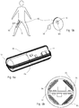
- one excitation coil 80 encircles a limb in which the device is implanted (here a thigh 104, the implant 10 being in the femoral bone 105)
- a suitable connector 85 joins the coil 80 with the external control device 90.
- the external antenna is not limited to one coil and could in fact comprise any number of them.
- the receiver coils within the implant not shown in the figures, will preferably be wound around the same axis, in order to maximize the coupling.
- Figure 5b illustrates an alternative arrangement in which the transmitter coil does not encircles the limb, but is essentially parallel to the thigh's skin.
- the transmitter coil 82 is bent, or even flexible, to conform to the limb's shape.
- the magnetic field is prevalently transverse relative to the treated limb, and the receiver coil or coils are wound in accordance to this. Since the coil needs not be worn around the limb, this solution is more comfortable.
- the invention is not limited to a single transmitter coil, and another coil could be placed symmetrically, to enhance the magnetic field at the implant.
- the invention encompasses arrangement with any number of excitation coils in whichever configuration.
- Figures 6a and 6b represent a possible disposition of some of the subunits contained in the hermetic capsule 20.
- the electronic circuit 33 realized on a printed circuit board is connected to a supercapacitor 32, and two receiving coils 88 are wound at 90° from one another in order to couple with a variable magnetic field predominantly in the transverse direction.
- This arrangement is suitable for use with the bent coil excitation of figure 5a .
- the coupling is essentially omnidirectional from all transverse directions, thus the transmitting coil 82 can be placed freely in this plane. It must be understood, however that the invention could also present a single coil, or a higher number of coils, in the hermetic capsule 20.
- the receiver unit is arranged to determine its orientation relative to the magnetic field, for example thanks to a plurality of differential receiving coils with different orientations and positions, This information can be used in real time to align the external excitation coil with the implant.
- the motor, the magnetic rotor and other components that may be present in the capsule are not shown in the figures 6a, 6b for simplicity's sake.
- the arrangement of the receiving coil 88 would preferably be adapted in order to optimize the coupling with an axial magnetic component rather than a transverse one.
- the receiving coil could for example be an axial solenoid wound around the circuit 33 and the supercapacitor 32.
- control unit 90 and/or the receiving unit 33 may be arranged to tune in real time the frequency of the excitation field, as well as the electric inductivity and/or capacity of the transmitter and receiver antennas, or of tank circuits attached thereto, in order to establish and maintain a resonance condition between them, thus enhancing the energy transfer between the external antennas 80, 82 and the receiving ones 84.
- the transmitter coil may be excited with high current intensities (typically between 1 and 50 A) in order to attain the desired power transfer.
- the control unit 90 is arranged for controlling the power transfer level in order to keep the temperature of the implanted device within predetermined limits.
- the device As the device is required to generate high forces (of the order of 1 kN or higher), it might be necessary to drive the electric motor with high power and current.
- the instantaneous power required by the motor might then be higher than the maximum power that can be transmitted wirelessly by the link 99 and, in this case, the charge time could be longer than the operate time.
- the implantable device could therefore be operated in a cyclic manner, with intermitted distraction period interleaved with longer charging periods.
- the use of supercapacitors for the energy storage 32 is especially advantageous in this kind of applications, owing to the high power density of these components.
- Communication between the external control unit 99 and the implanted processor 33 can be obtained by any suitable modulation of the magnetic field generated by the antenna 80. Changes in the power consumed in the receiver circuit are visible on the transmitter side through the backscatter effect. It would also be possible, however, to create a radio wireless link between the controller 80 and the implanted processor on an independent frequency, and using separate antennas.
- the magnetic field generated by the antenna 80 could be modulated by a FSK (Frequency-Shift Keying) scheme.
- FSK Frequency-Shift Keying
- This modulation scheme however, interferes with the resonance condition. To maintain resonance one should either limit the modulation depth to less than the width of the resonance peak, with a consequent degradation of the link budget, or increase the bandwidth of the tuning controller so that it can follow the modulation shifts.
- ASK Amplitude-Shift Keying
- the information transmitted from the external unit 90 to the implanted device is encoded according to a double-modulation principle in which different symbols are encoded as predetermined sequences of frequency and/or amplitude shifts.
- the magnetic field is modulated to represent two values, denoted '0' and '1', which are encoded by different temporal rates of amplitude changes.
- Other factors are however possible.
- the modulation could be phase-synchronous with the carrier, as in the example, and the symbol duration is preferably constant.
- each symbol (or bit in this case) is encoded by an interval of 40 RF cycles, that is the least common multiple of 8 and 10, but other factors can also be used.
- Asynchronous modulation is also possible and can be advantageous in certain conditions.
- the control unit 33 could be equipped with a limited-power microcontroller that operates on an internal clock whose frequency may not be very exact.
- the carrier's frequency may be shifted in order to achieve a resonance condition at the transmitting antenna 80.
- an asynchronous signal available at the receiving antenna could be processed by a demodulator stage and either an hardware UART interface a suitable piece of software of the microcontroller. If the modulation is asynchronous, it is preferable that the carrier frequency be sufficient high in comparison to the data speed, which is the case in the present application.
- the modulation scheme of figure 8 can be regarded as a double modulation in which the original message 130, consisting in an arbitrary bit sequence, is first modulated by FSK, obtaining a variable-frequency digital signal 134 which is then modulated by ASK and gives the double-modulated signal 138.
- This double modulation could also be used in real implementation of the modulator of the device of the invention.
- the signal 138 could however also be directly synthesized, or obtained by any suitable algorithm.
- the frequency of the amplitude changes which could be indicated as 'chip rate' is fairly high. Assuming a carrier frequency of 20-30 kHz, which is typical, the chip rate would be of 2-3 kHz or higher, well above the region of spectrum of body movements. As a consequence, the amplitude variations caused by motion can be filtered out fairly easily in the receiver thus recovering the frequency-variable message 134 that delivers the original message 130 by FSK-demodulation. As above, other demodulation schemes can be adopted by concrete implementations.
- the modulation has negligible impact on the frequency of the modulated signal and resonant wireless charging is possible.
- the double modulation scheme proposed has the advantage that the average AC current of signal 138 is constant. The power transferred does not depend on the modulation state.
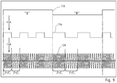
- the present invention employs a double FSK modulation scheme, wherein the message 130, consisting in a bit sequence, is first modulated by FSK obtaining a variable-frequency digital signal 134 which is in turn used to generate the double-modulated AF signal 138.
- Values '1' and '0' are encoded by the different rates of frequency change in the double-modulated 138, in contrast with the variant of f figure 8 , which used different rates of amplitude changes to encode the '1', '0' values.
- the two stages of modulation of figure 9 are presented here simply by way of example, and the double-modulated signal 138 could be synthesized directly from the message 130 without generating the intermediate signal 134.
- the modulation can be synchronous or asynchronous with the carrier phase, with the second solution being preferable when the implanted controller 33 is equipped with a simple microcontroller.
- This modulation system presents, as the previous one, the advantage of a high immunity from motion-induced amplitude fluctuations. Moreover, since the amplitude is constant, the transferred power can be higher.
- the external control unit 90 includes a tuning system, arranged to tune automatically the resonance frequency of the emitter antenna 80, or of a tank circuit connected thereto, in order to follow the frequency variations of the modulated signal 138.
- the uplink channel of communication from the implanted controller 33 to the external unit 90 is preferably realized, as already mentioned, utilizing the backscatter effect: the implanted microcontroller 33 modulates the load seen by the receiving antenna 84, and these variations are sensed as voltage or current signals at the transmitter antenna 80.
- the advantage of this manner of communicating is that the implanted controller needs not include a highfrequency generator, but simply has to controls a variable load, which, in a simple realization, could reduce to a transistor connected across the terminals of the coil 84. Other dispositions are also possible, however.
- the uplink channel adopts also a modulation scheme, or better a double modulation scheme, in order to avoid movement-induced errors.
- Values '1' and '0' are encoded by the different rates of frequency change. As per the downlink case, this modulation could be generated by a standard microcontroller.
- the invention thus proposes a use of an AC magnetic field to transfer data or data and energy from an external unit to a device implanted in a human or animal body, wherein the AC magnetic field is double-modulated in frequency and/or amplitude by a digital signal having variable rate, the rate of change of the digital signal representing symbols or bits of information. Even if this modulation scheme has been presented in connection with a distractor device, it could be usefully adopted for any kind of implanted device, including those that do not include a mechanical actuator.
Landscapes
- Health & Medical Sciences (AREA)
- Orthopedic Medicine & Surgery (AREA)
- Life Sciences & Earth Sciences (AREA)
- Surgery (AREA)
- Engineering & Computer Science (AREA)
- General Health & Medical Sciences (AREA)
- Veterinary Medicine (AREA)
- Public Health (AREA)
- Nuclear Medicine, Radiotherapy & Molecular Imaging (AREA)
- Biomedical Technology (AREA)
- Heart & Thoracic Surgery (AREA)
- Medical Informatics (AREA)
- Molecular Biology (AREA)
- Animal Behavior & Ethology (AREA)
- Neurology (AREA)
- Physics & Mathematics (AREA)
- Electromagnetism (AREA)
- Prostheses (AREA)
- Surgical Instruments (AREA)
Description
- The present invention relates, in embodiments, to an implantable device comprising an autonomously supplied mechanical actuator: for example, but not exclusively, an orthopedic distractor comprising an electrical motor in a hermetic capsule and a biocompatible transmission system arranged for bidirectional displacement of bones or skeletal elements.
- Orthopedic distractors find application in the therapy of a plurality of diseases and malformations, in particular, but not exclusively, in the extension of long bones, but also in the surgical therapy of the spine, the jawbone, or other skeletal districts. Such techniques employ external distractor devices fixed on the bone and, more and more, internal devices that are fully implanted in the body, for example centromedullary distractor nails for the extension of long bones, jack distractors for the spine therapy, and other specialized forms of active implants.
-
FR2961386 US200629683 relates to a distractor driving a lead-screw device.WO9100065 - A problem common to these devices is that of ensuring the biocompatibility of the implant containing electric motors. These devices include in fact several materials, for example control electronics, rare-earth magnets, electric windings and magnetic circuits that must not enter in contact with body tissues. The same limitations apply also to the battery used for the energy supply.
US6245075 describes a distractor with an internal or external power supply, and in which the distraction action is ensured by a hydraulic actuator. Other similar solutions are known byUS5626581 andUS6416516 -
US7753915 describes a centromedullary nail with a magnetic rotor that is driven in rotation by a rotating magnetic field generated by coils external to the body andUS2004023623 describes a distractor in which the electric motor is not implanted, but external to the body, and the motion is magnetically transmitted to an internal actuator. These devices solve the problem of enclosing the potentially non-compatible components, but are not fully contained in the body, and require a relatively bulky external part that can be a nuisance for the patient. - Other forms of implantable devices comprising electromechanical actuators are also known, for example in the form of implantable pumps for drug delivery. In these devices as well as in the electromechanical distractors separation of the electric motor, electronic units and battery pack from the body tissues is of paramount importance.
-
WO2010/061391 discloses an automatic distractor for adjusting alveolar ridge elevation or expansion distraction gap in a patient, wherein a motor and a reduction gear are enclosed in a sealed cylinder. - It is therefore an aim of the present invention to provide a biocompatible implantable device that comprises a mechanical actuator and can operate without relying on external elements or power sources.
- According to the invention, this goal is achieved by means of the object of the annexed claims, and in particular by means of an implantable device comprising a driving unit and a kinematic assembly joined together: the driving unit comprising an electric motor driving a first magnetic rotor; the kinematic assembly comprising a second magnetic rotor, magnetically coupled to said first magnetic rotor such that it can be rotationally driven by the motor, and an actuator driven by the second rotor, characterized by an hermetic capsule that encloses the driving unit, the electric motor, and the first rotor; and in that the second magnetic rotor is outside the hermetic capsule.
- Examples of realization modes of the invention are indicated in the following description and illustrated by the drawings in which:
-
Figure 1 represents in a simplified section view, a possible embodiment of the present invention applied to an intramedullary distractor for lengthening of long bones. -
Figure 2a shows a detail of a magnetic transmission included in an embodiment of the present invention. -
Figure 2b shows again the magnetic transmission of an embodiment of the invention, one of the magnetic rotors having been moved away for clarity. -
Figure 3a and3b illustrate a possible embodiment of the present invention that is a spine distractor -
Figure 4 shows a mandibular distractor that is an embodiment of the present invention. -
Figures 5a and5b show, in simplified schematic form, two possible variant of an embodiment of the invention that includes an external control unit wirelessly connected with the implantable device. -
Figures 6a and 6b show schematically a possible structure of an implanted electronic module with receiving antennas and an energy storage suitable for use with the embodiments offigures 5a and5b . - The arrangement of
figures 5a-b and6a-b is also the object of the block diagram offigure 7 . -
Figures 8 and9 illustrates a possible modulation scheme for the wireless link of the previous embodiments. - A possible embodiment of the present invention is an intramedullary nail distractor for the correction of length deficit in long bones, like for example the femur, tibia, humerus, or any other long bone. As it is known in the art cited above, a possible therapy for such conditions comprises the surgically insertion in the medullary cavity of the target bone of a distracting nail comprising an actuator that allows to modify its overall length, and that can exert a sufficient linear force so as to promote bone growth on both sides of an artificial fracture line. Typically the implant is operated during an extended time period according to a specified elongation plan and is usually left in place, as a passive structural intramedullary nail, once the bone has reached the desired length. The relative linear speed of the
connecting ends - According to this embodiment, as illustrated by
figures 1 and2a, 2b , the implantable device comprises adriving unit 25 and akinematic assembly 27 coaxially joined together: thedriving unit 25 is placed at one extremity of the intramedullary nail, and includes anelectric motor 35 that can be set into rotation by a command unit, not visible in the figure, and a source ofelectrical energy 32, for example a stack of lithium cells or another suitable primary or secondary (rechargeable) electrical battery or supercapacitors. - The
driving unit 25 is fully enclosed into ahermetic capsule 20, for example made of titanium, PEEK, or of any suitable biocompatible material. The purpose of the capsule is to prevent the ingress of body fluids into the space that encloses the electronics, the electric motor, optionally including a first reduction stage, the battery, and a magnetic rotor that is a first stage of a magnetic coupling, and effectively prevent any contact between these component and body tissue. Preferably the capsule is hermetically sealed or welded and does not present any opening so as to guarantee containment for an essentially indefinite time. More preferably, the whole driving unit is contained in a double sealed capsule so as to prevent any contamination. - In a possible variant of the invention, the battery pack may be contained in a separate hermetic capsule distinct from that encloses the
motor 35, and the capsule have pass-through electric connectors to allow the transmission of electric energy from one to the other. - In some occasions, it may be advantageous to provide a separate energy source, to which the implantable device is connectable. The energy source could be positioned inside or outside the body and transmit the energy to the implantable device by means of an appropriate wired or wireless connection. This variant of the invention is particularly suitable, for example, when the actuator must be operated during a long time span, or when a suitable autonomous battery could not fit in the space available at implantation site. According to the needs, the implantable device may be entirely dependent from the external energy supply for its functioning, or include a rechargeable accumulator that can be replenished by the external energy source.
- Wireless energy transmission could be obtained by electric or magnetic induction, or by an ultrasonic converter, or by any other suitable energy transmission means.
- The
electric motor 35 is connected, directly or indirectly, to a firstmagnetic rotor 37, also comprised in thecapsule 20 that presents an arrangement of alternate magnetic poles. Its rotation is transmitted, by magnetic coupling, to a secondmagnetic rotor 41 outside thecapsule 20, magnetically coupled to said first magnetic rotor such that it can be rotationally driven by the motor.Figures 2a and 2b represent a possible arrangement of such coupledrotors - In most orthopedic applications displacement speeds are very low, and the forces exerted are fairly high, thus requiring a reduction system. In the presented example, as shown by
figures 2 and 3a , the reduction is obtained by agearbox 45, for example a cascade of planetary reductions, and by the final lead-screw 48 andnut 49 transmission that transforms the rotary motion at the output of thegear reduction 45 into a linear motion of theplunger 60 relative to thesleeve 50. A reduction stage between theelectric motor 35 and the firstmagnetic rotor 37, inside thehermetic capsule 20 is also possible. At least part of the reduction system of this embodiment, comprising theplanetary stages 45, and the lead-screw and nut assembly is not enclosed into a hermetic capsule and, therefore, it can enter in contact with body fluids, and is in fact lubricated by body fluids. Accordingly, it is integrally built with biocompatible materials like titanium, Cobalt-Chrome alloy, nitinol, BioDur® 108 alloy, stainless steel, Polyethylene, PEEK, PET, PTFE, biocompatible ceramic, or any other suitable biocompatible material. Biocompatible coatings like for example ADLC can be also applied. - In a typical application, the reduction ratio of the
gearbox 45 is comprised between 500:1 and 2000:1. For example, a cascade of five 4:1 planetary stages could be used to achieve an overall reduction ratio of 1024:1. In such manner, assuming a rotation speed of the about 1000 rpm for themotor 35, the lead-screw 40 could turn at about one revolution per minute. - In other non-represented variants, the reduction system could use harmonic reducers, wobbling gears, cycloidal gears, cyclo-drive reducers, or other transmission systems achieving the desired transmission ratios.
- In clinical limb-lengthening practice, the distraction plan spans over a periods of several days or weeks, during which the patient is encouraged to move and exercise the treated limb. Accordingly, the
gearbox 45 and the lead-screw/nut assembly axial bearings 46 in thegearbox 45. In a preferred embodiment the bearings have titanium cages and ceramic balls or rollers and are of a double-acting construction, arranged for supporting thrust both in the distraction and in the contraction directions. -
Figure 2a shows, perhaps more clearly, the disposition of themagnetic rotors second rotor 41, which is not protected inside thehermetic capsule 20, has preferably the magnetic materials covered by a protective biocompatible material (not visible). Advantageously, themotor 35 in thehermetic capsule 20, themagnetic rotors reduction system 45, the lead-screw 48, and thenut 49 are all coaxially aligned and each element is directly connected to the following one, thus, the transmission is efficient and compact. - As mentioned above, the actuator of the invention is wholly contained in the implantable nail, and does not rely on external sources of energy or pressurized fluids for its operation. Another advantageous feature of the invention is that the whole transmission chain is reversible, in the sense that the linear relative motion of the attachment points 61 and 31 can be in both directions, either lengthening or shortening the implantable nail. Thanks to this feature that the distraction can be reversed, if needed.
- Preferably, the driving unit also comprises a remotely-controllable command circuit that determines the rotation or the stop of the
motor 35. Thanks to this feature, the motor can be operated after the implantation, based on a predetermined post-operatory plan and/or on clinical and X-ray observations. Several remote control systems can be accommodated in the frame of the invention. In a possible variant, the command circuit includes magnetic field sensors, for example hall sensors. In this manner, a surgeon can control the operation of themotor 35 by placing permanent magnet at predetermined positions outside the implanted limb, preferably in this case, the command circuit has two magnetic field sensors at spaced-apart positions, one for operating the actuator in the normal, lengthening direction, and another for reversing the distraction. In a more preferred variant, however, the remote control of the driving unit involves a wireless data link, as it will be explained in the following. - In the example shown, the lead-screw transmission is preferably self-locking, in the sense that the nail normally resists to axial loads without changing its length unless the electric motor is active. If needed, an active locking mechanism can be added to the implant. The locking is preferably assisted by short-circuiting the electric motor, and may involve any suitable form or mechanical or electric brake.
- The invention admits also other forms of remote control, for example by radio transmission, near-field electromagnetic communication, ultrasounds, or any other suitable wireless communication system.
- The variants of
figures 1 ,2 ,3a ,3b are specially adapted for an implantation in the medullary canal of long bones. This is not, however, the only application of the invention.Figures 3a ,3b illustrate a variant of the invention applicable to other parts of the skeleton, in particular in the treatment of the spine and of scoliosis. In this variant the lead-screw 48 operates an articulatedjack 13 that can be used as implantable spine distractor.Figure 4 , on the other hand, illustrates the possible implantation of adevice 15 according to the invention used as a Cranio-Maxillo distractor. In this application, the implant is fixed outside of a bone, in this case a mandible. - Other applications of the inventive implant are possible, including limb length correction, both congenital and posttraumatic; poliomyelitis; pseudoarthrosis; bone stump extension after amputations; bone transport after tumor resection; unilateral or bilateral impaired or abnormal growth; partial or total hip replacement, tumor prosthetic knee; cosmetic lengthening; Orthognatic surgery; correction of jaw deformities; Craniomaxillofacial distraction; Alveolar Ridge distraction; Multi-vector distraction; and, in the spine district, non-fusion scoliosis and other orthopedic conditions.
- The invention is not limited to orthopedic application either, other not represented embodiments may include instead of the lead-screw and nut, different actuators like for example an impeller, positive displacement pump, or any other device requiring a movement or a displacement.
- According to an embodiment, the present invention comprises, in the implantable device, a
rechargeable energy storage 32 that could comprise for example one or several lithium-ion cells, or other electrochemical cells, or a high-value capacitor, like for example a double-layer capacitor, a supercapacitor, a pseudocapacitor, or any suitable energy storage device. The energy necessary to the functioning of the implantable device is received wirelessly by means of suitable antennas from anexternal control unit 90 and accumulated in the storage means 32. -
Figure 7 illustrates in block fashion the structure of this embodiment of the invention. Thehermetic capsule 20 includes, in addition to the magnetic rotor, a receivingantenna 84 connected to a controlelectronic unit 33. Theantenna 84 picks up an AC or RF signal generated by a transmittingantenna 80 and anexternal module 90, which is then rectified by theelectronic circuit 33 and stored in the storage means 32. Theelectronic circuit 33 comprises also a motor drive subunit that is arranged for driving themotor 35 according to a determined distraction plan, for example. Advantageously, theelectronic circuit 33 is arranged for charging the storage means 32 when theantenna 84 picks up a sufficient AC or RF signal, and can operate autonomously using the electric energy accumulated in the storage means when theexternal excitation antenna 80 is inactive or detached from the patient. In this manner, the patient in whom the device of the invention is implanted needs not be constantly in connection with the external device. In some cases, however, for example in the distraction therapy of the femoral bone, the energy required may exceed the capacity of thestorage 32, and the patient will need to wear the external device during treatment. The implantable device may continue to function between distraction cycles for diagnostic purposes, however. - Importantly, the
electronic unit 33, theenergy storage 32, themotor 35, and themagnetic rotor 37 that is driven by the motor, are enclosed in a hermetic volume defined by thecapsule 20, thereby avoiding any risk of contamination or lack of biocompatibility. At the same time, the implantable device can be operated for an indefinite time by providing an adequate number and duration of recharges via thewireless link 99. As it has already been mentioned, thehermetic capsule 20 may include also other elements, like for example a reducing unit between themotor 35 and themagnetic rotor 37, or additional electronic elements like a wireless radio interface, sensors for acquiring force, temperature, or other useful variables, processing units, memory means, and so on. - Tests have shown that a suitable level of electric power can be transmitted through the
wireless link 99 also when the receiving antennas is enclosed into an integralmetallic capsule 20, by judiciously choosing the excitation frequency and/or the capsule material. If an especially low level of loss is sought, the capsule 22 could be realized in a suitable dielectric biocompatible material, for example PEEK, bioceramic, or bioglass. A metallic capsule is however preferable, both for its superior strength, and because it shields the inner electronic elements from unwanted electronic interference. - The best results have been obtained so far with low-frequency magnetic excitation for example comprised between 10 kHz and 100 kHz. In this region of the electromagnetic spectrum, the receiver and transmitter antennas can effectively be realized by suitably dimensioned coils. Other form of antennas and other values of frequency are however also possible.
- Advantageously, the
wireless link 99 can be used not only to charge theenergy storage 32, but also for exchanging information in digital form between theexternal control unit 90 and theelectronic module 33. Preferably the transmission is bidirectional: the downlink (from thecontroller unit 90 to the implanted device) can be used for example to download the distraction plan, which the physician can modify or adapt along the treatment based on the clinical at its disposal. The uplink in the reverse direction can be used to transfer several information including clinical parameters and/or diagnostic information relative to the actuator itself. Such information may comprise, for example, the linear position of the lead-screw i.e. the amount of distraction so far attained in real time, the force acting on the implant, the body temperature, the temperature of the actuators, the state of the storage unit, and so on. Usefully, theelectronic unit 33 may be arranged to transmit to thecontroller 90 the intensity of the variable RF or AC field, and this information can be in real time used to position theexcitation antenna 80 and optimize its coupling with thereceiver 84. - In a preferred variant, the
control unit 90 includes a rechargeable battery and can operate without a permanent connection to the mains electric network. - The inventive system represented in
figure 7 may thus be subdivided in three distinct zones: - The
external zone 110 includes thecontrol unit 90, the transmittingcoil 80, and possiblyother devices 120 communicating with thecontrol unit 90, for example a remote computer or a remote mobile device establishing an internet connection with thecontrol unit 90. The devices in this zone are not implanted and have no or limited contact with the human body. - The protected
zone 112 includes all the elements of the implant enclosed by thehermetic capsule 20. Thecapsule 20 is so constructed that these elements cannot under any circumstance come into contact with the living tissues. Preferably the hermetic capsule has a continuous impervious boundary that is not interrupted by feedthrough connectors, passages or openings of any kind. Elements in the protected zone can interact with theexternal zone 110 by electromagnetic interaction via theantenna 84, and with elements in the 'wet'zone 115 by the magnetically coupledrotors - Finally the 'wet'
zone 115 encompasses at least the secondmagnetic rotor 41, thereducer 45, and the actuator, which can be for example a lead-screw 48 or another suitable mechanical device. These elements may be designed to operate in continuous contact with body fluids and live tissues. -
Figures 5a and5b illustrate two possible setups that may be used to wirelessly couple theexternal control unit 90 with the implantable device. Infigure 5a oneexcitation coil 80 encircles a limb in which the device is implanted (here athigh 104, theimplant 10 being in the femoral bone 105) Asuitable connector 85 joins thecoil 80 with theexternal control device 90. - Even if the figure does not show it, it must be understood that the external antenna is not limited to one coil and could in fact comprise any number of them. One could for example conceive to use two equal parallel coils in a Helmholtz configuration for increasing the intensity and the uniformity of the magnetic at the implantation site. In many cases, however, one single coil is sufficient, and, the placement of the
transmitter coil 80 is not critical. This arrangement generates a magnetic field that is prevalently axial relative to the treated limb. The receiver coils within the implant, not shown in the figures, will preferably be wound around the same axis, in order to maximize the coupling. -
Figure 5b illustrates an alternative arrangement in which the transmitter coil does not encircles the limb, but is essentially parallel to the thigh's skin. Preferably, as in the drawing, thetransmitter coil 82 is bent, or even flexible, to conform to the limb's shape. In this case, the magnetic field is prevalently transverse relative to the treated limb, and the receiver coil or coils are wound in accordance to this. Since the coil needs not be worn around the limb, this solution is more comfortable. - As above, also this variant the invention is not limited to a single transmitter coil, and another coil could be placed symmetrically, to enhance the magnetic field at the implant. The invention encompasses arrangement with any number of excitation coils in whichever configuration.
-
Figures 6a and 6b represent a possible disposition of some of the subunits contained in thehermetic capsule 20. Theelectronic circuit 33 realized on a printed circuit board is connected to asupercapacitor 32, and two receiving coils 88 are wound at 90° from one another in order to couple with a variable magnetic field predominantly in the transverse direction. This arrangement is suitable for use with the bent coil excitation offigure 5a . Thanks to the double crossed receiving coils, the coupling is essentially omnidirectional from all transverse directions, thus the transmittingcoil 82 can be placed freely in this plane. It must be understood, however that the invention could also present a single coil, or a higher number of coils, in thehermetic capsule 20. - In a possible variant (not represented) the receiver unit is arranged to determine its orientation relative to the magnetic field, for example thanks to a plurality of differential receiving coils with different orientations and positions, This information can be used in real time to align the external excitation coil with the implant.
- The motor, the magnetic rotor and other components that may be present in the capsule are not shown in the
figures 6a, 6b for simplicity's sake. - Should the axial disposition of
figure 5a be preferred, the arrangement of the receiving coil 88 would preferably be adapted in order to optimize the coupling with an axial magnetic component rather than a transverse one. The receiving coil could for example be an axial solenoid wound around thecircuit 33 and thesupercapacitor 32. - Preferably, the
control unit 90 and/or the receivingunit 33 may be arranged to tune in real time the frequency of the excitation field, as well as the electric inductivity and/or capacity of the transmitter and receiver antennas, or of tank circuits attached thereto, in order to establish and maintain a resonance condition between them, thus enhancing the energy transfer between theexternal antennas - Since the
wireless connection 99 enables data upload from the implanted device to the external controller, this channel can be used to feedback information that are used to achieve and maintain resonance in a control loop. Optionally, thecontrol unit 90 is arranged for controlling the power transfer level in order to keep the temperature of the implanted device within predetermined limits. - As the device is required to generate high forces (of the order of 1 kN or higher), it might be necessary to drive the electric motor with high power and current. The instantaneous power required by the motor might then be higher than the maximum power that can be transmitted wirelessly by the
link 99 and, in this case, the charge time could be longer than the operate time. The implantable device could therefore be operated in a cyclic manner, with intermitted distraction period interleaved with longer charging periods. The use of supercapacitors for theenergy storage 32 is especially advantageous in this kind of applications, owing to the high power density of these components. - Communication between the
external control unit 99 and the implantedprocessor 33 can be obtained by any suitable modulation of the magnetic field generated by theantenna 80. Changes in the power consumed in the receiver circuit are visible on the transmitter side through the backscatter effect. It would also be possible, however, to create a radio wireless link between thecontroller 80 and the implanted processor on an independent frequency, and using separate antennas. - The magnetic field generated by the
antenna 80 could be modulated by a FSK (Frequency-Shift Keying) scheme. Advantageously, FSK is relatively insensitive to amplitude changes that may be induced, for example, by patient's motion, and has no impact on the power transfer. This modulation scheme, however, interferes with the resonance condition. To maintain resonance one should either limit the modulation depth to less than the width of the resonance peak, with a consequent degradation of the link budget, or increase the bandwidth of the tuning controller so that it can follow the modulation shifts. - ASK (Amplitude-Shift Keying) is another possible modulation that could be used both in the downlink channel and in the uplink (backscatter) one. It is relatively simple to implement, but it presents some drawbacks:
- ASK is sensitive to all sort of changes in the propagation conditions and, in particular, to any movement or orientation change of the transmitter coil or of the implant relative to one another. This means that the decoder should be equipped to discriminate these extraneous variations from the modulation.
- In all forms of ASK (especially in On-Off Keying), the duty-cycle of the carrier is significantly lower than 100% and, consequently, the power that can be transmitted on the wireless channel is considerably reduced.
- According to a variant of the invention, the information transmitted from the
external unit 90 to the implanted device is encoded according to a double-modulation principle in which different symbols are encoded as predetermined sequences of frequency and/or amplitude shifts. In a preferred embodiment, represented byfigure 8 , the magnetic field is modulated to represent two values, denoted '0' and '1', which are encoded by different temporal rates of amplitude changes. In the represented example '0' is encoded by a square amplitude modulation at frequency fM =fc /8, where fM and fc denote, respectively, modulation and carrier frequencies, while '1' is encoded by a square amplitude modulation at frequency fM =fc /10. Other factors are however possible. - The modulation could be phase-synchronous with the carrier, as in the example, and the symbol duration is preferably constant. In the example, each symbol (or bit in this case) is encoded by an interval of 40 RF cycles, that is the least common multiple of 8 and 10, but other factors can also be used.
- Asynchronous modulation is also possible and can be advantageous in certain conditions. In particular, due to limitation of space and energy, the
control unit 33 could be equipped with a limited-power microcontroller that operates on an internal clock whose frequency may not be very exact. At the same time the carrier's frequency may be shifted in order to achieve a resonance condition at the transmittingantenna 80. In this case, an asynchronous signal available at the receiving antenna could be processed by a demodulator stage and either an hardware UART interface a suitable piece of software of the microcontroller. If the modulation is asynchronous, it is preferable that the carrier frequency be sufficient high in comparison to the data speed, which is the case in the present application. - Expressed in another way, the modulation scheme of
figure 8 can be regarded as a double modulation in which theoriginal message 130, consisting in an arbitrary bit sequence, is first modulated by FSK, obtaining a variable-frequencydigital signal 134 which is then modulated by ASK and gives the double-modulatedsignal 138. This double modulation could also be used in real implementation of the modulator of the device of the invention. Thesignal 138 could however also be directly synthesized, or obtained by any suitable algorithm. - Advantageously in this mode of modulation the frequency of the amplitude changes, which could be indicated as 'chip rate' is fairly high. Assuming a carrier frequency of 20-30 kHz, which is typical, the chip rate would be of 2-3 kHz or higher, well above the region of spectrum of body movements. As a consequence, the amplitude variations caused by motion can be filtered out fairly easily in the receiver thus recovering the frequency-
variable message 134 that delivers theoriginal message 130 by FSK-demodulation. As above, other demodulation schemes can be adopted by concrete implementations. - Another advantage of the double-modulation scheme described above is that the resultant signal has essentially constant frequency f=fc . The modulation has negligible impact on the frequency of the modulated signal and resonant wireless charging is possible.
- Further, the double modulation scheme proposed has the advantage that the average AC current of
signal 138 is constant. The power transferred does not depend on the modulation state. - According to another possible modulation scheme, illustrated in
figure 9 , the present invention employs a double FSK modulation scheme, wherein themessage 130, consisting in a bit sequence, is first modulated by FSK obtaining a variable-frequencydigital signal 134 which is in turn used to generate the double-modulatedAF signal 138. The double-modulatedsignal 138 consists in a series of intervals containing a pure tone having either of two possible frequencies: f=f1 and f=f2 . Values '1' and '0' are encoded by the different rates of frequency change in the double-modulated 138, in contrast with the variant of ffigure 8 , which used different rates of amplitude changes to encode the '1', '0' values. - As in the previous case, the two stages of modulation of
figure 9 are presented here simply by way of example, and the double-modulatedsignal 138 could be synthesized directly from themessage 130 without generating theintermediate signal 134. As seen previously, the modulation can be synchronous or asynchronous with the carrier phase, with the second solution being preferable when the implantedcontroller 33 is equipped with a simple microcontroller. - This modulation system presents, as the previous one, the advantage of a high immunity from motion-induced amplitude fluctuations. Moreover, since the amplitude is constant, the transferred power can be higher.
- While the system of
figure 8 operated at essential constant frequency, the frequency in this variant is variable. Preferably theexternal control unit 90 includes a tuning system, arranged to tune automatically the resonance frequency of theemitter antenna 80, or of a tank circuit connected thereto, in order to follow the frequency variations of the modulatedsignal 138. - Tests and simulations have shown that it is possible to design a tunable tank circuit for the
antenna 80 that can be controlled sufficiently fast to achieve an adequate data transfer speed for the present application, while maintaining the resonance condition, and a maximal power transfer. - The uplink channel of communication from the implanted
controller 33 to theexternal unit 90 is preferably realized, as already mentioned, utilizing the backscatter effect: the implantedmicrocontroller 33 modulates the load seen by the receivingantenna 84, and these variations are sensed as voltage or current signals at thetransmitter antenna 80. The advantage of this manner of communicating is that the implanted controller needs not include a highfrequency generator, but simply has to controls a variable load, which, in a simple realization, could reduce to a transistor connected across the terminals of thecoil 84. Other dispositions are also possible, however. - Preferably, the uplink channel adopts also a modulation scheme, or better a double modulation scheme, in order to avoid movement-induced errors. In a preferred variant, which is not however the only one possible within the scope of the invention, the load on the
antenna 84 is switched at either of two possible frequencies: f=f1 and f=f2 . Values '1' and '0' are encoded by the different rates of frequency change. As per the downlink case, this modulation could be generated by a standard microcontroller. - The invention thus proposes a use of an AC magnetic field to transfer data or data and energy from an external unit to a device implanted in a human or animal body, wherein the AC magnetic field is double-modulated in frequency and/or amplitude by a digital signal having variable rate, the rate of change of the digital signal representing symbols or bits of information. Even if this modulation scheme has been presented in connection with a distractor device, it could be usefully adopted for any kind of implanted device, including those that do not include a mechanical actuator.
-
- 10
- intramedullary distractor
- 13
- spine distractor
- 15
- Cranio-Maxillo distractor
- 20
- hermetic capsule
- 25
- driving unit
- 27
- kinematic assembly
- 31
- attachment region
- 32
- energy source or rechargeable energy storage
- 33
- implanted control unit, microcontroller
- 35
- motor
- 37
- magnetic rotor
- 40
- lead-screw
- 41
- magnetic rotor
- 44
- radial bearing
- 45
- planetary reductions
- 46
- axial bearing
- 48
- actuator, lead-screw
- 49
- nut
- 50
- sleeve
- 60
- plunger
- 61
- attachment region
- 71
- flat pusher
- 72
- flat pusher
- 80
- charging coil (axial)
- 82
- charging coil (bent)
- 84
- receiver antenna
- 85
- connector
- 90
- control unit
- 103
- maxilla
- 104
- leg
- 105
- femoral bone
- 110
- External zone
- 112
- Protected zone
- 115
- 'Wet' zone
- 120
- network-connected device
- 130
- message
- 134
- FSK modulated signal
- 138
- double-modulated signal
Claims (13)
- Implantable device (10,13,15) comprising a driving unit (25) and a kinematic assembly (27) joined together: the driving unit (25) comprising an electric motor (35) driving a first magnetic rotor (37); the kinematic assembly (27) comprising a second magnetic rotor (41), magnetically coupled to said first magnetic rotor (37) such that it can be rotationally driven by the motor (35), and an actuator driven by the second rotor (41), wherein an hermetic capsule (20) encloses the driving unit (25), the electric motor, and the first rotor; and wherein the second magnetic rotor (41) is outside the hermetic capsule (20);
the hermetic capsule (20) further including a control unit (33) arranged for driving the electric motor (35), and a remote control system based on wireless communication for remotely controlling the control unit (33). - Implantable device according to claim 1, wherein the control unit (33) is arranged for wirelessly exchanging data and/or energy with an external device (90).
- Implantable device according to any one of the previous claim, comprising a receiving antenna (84).
- Implantable device according to claim 3, the antennas being realized as one or several receiving coils (84).
- Implantable device according to any one of claims from 2 to 4, wherein the coupling between the implantable device and the external device is essentially omnidirectional.
- Implantable device according to the previous claim, the antenna (84) comprising a pair of crossed receiving coils, in particular, two receiving coils (88) wound at 90° from one another.
- Implantable device according to any one of claims 4 and 5, wherein the control unit (33) is arranged to convert an AC signal picked up by the one or several receiving coils (84) and charge an energy storage means (32) comprised in the hermetic capsule (20).
- Implantable device according to the previous claim, the AC signal being a low frequency signal, preferably a signal comprised between 10 kHz and 100 kHz.
- Implantable device according to any one of claims 2 to 7, wherein the control unit (33) is arranged for demodulating a message carried by an AC magnetic field generated by said external device (90), the AC magnetic field being double-modulated in frequency and/or amplitude.
- A system comprising an implantable device according to one of the claims 2 to 9 and an external control device (90) with a transmitting coil (80) arranged to generate and maintain a resonant magnetic field for charging an energy storage means (32) comprised in the hermetic capsule (20).
- System according to the previous claim, wherein the external control device (90) is arranged for generating an AC magnetic field that carries a message, the AC magnetic field being double-modulated in frequency and/or amplitude.
- System according to the previous claim, comprising a control means arranged to tune automatically the resonance frequency of the emitter antenna (80), or of a tank circuit connected thereto, in order to follow the frequency variations of the modulated signal (138).
- System according to any one of claims from 11 to 12, wherein the external control device (90) is arranged for receiving a backscattered signal from the control unit (33).
Applications Claiming Priority (2)
| Application Number | Priority Date | Filing Date | Title |
|---|---|---|---|
| EP14158156.1A EP2915496B2 (en) | 2014-03-06 | 2014-03-06 | Implantable device |
| PCT/EP2015/054719 WO2015132382A1 (en) | 2014-03-06 | 2015-03-06 | Implantable device |
Publications (2)
| Publication Number | Publication Date |
|---|---|
| EP3113703A1 EP3113703A1 (en) | 2017-01-11 |
| EP3113703B1 true EP3113703B1 (en) | 2019-06-26 |
Family
ID=50238209
Family Applications (2)
| Application Number | Title | Priority Date | Filing Date |
|---|---|---|---|
| EP14158156.1A Active EP2915496B2 (en) | 2014-03-06 | 2014-03-06 | Implantable device |
| EP15709457.4A Active EP3113703B1 (en) | 2014-03-06 | 2015-03-06 | Implantable device |
Family Applications Before (1)
| Application Number | Title | Priority Date | Filing Date |
|---|---|---|---|
| EP14158156.1A Active EP2915496B2 (en) | 2014-03-06 | 2014-03-06 | Implantable device |
Country Status (5)
| Country | Link |
|---|---|
| US (1) | US10251676B2 (en) |
| EP (2) | EP2915496B2 (en) |
| CN (1) | CN106456216B (en) |
| ES (2) | ES2617556T5 (en) |
| WO (1) | WO2015132382A1 (en) |
Families Citing this family (39)
| Publication number | Priority date | Publication date | Assignee | Title |
|---|---|---|---|---|
| EP2367486B1 (en) * | 2008-10-31 | 2024-07-10 | Implantica Patent Ltd. | Device for bone adjustment with anchoring function |
| US9179938B2 (en) * | 2013-03-08 | 2015-11-10 | Ellipse Technologies, Inc. | Distraction devices and method of assembling the same |
| US10238427B2 (en) * | 2015-02-19 | 2019-03-26 | Nuvasive Specialized Orthopedics, Inc. | Systems and methods for vertebral adjustment |
| WO2017066774A1 (en) * | 2015-10-16 | 2017-04-20 | Nuvasive Specialized Orthopedics, Inc. | Adjustable devices for treating arthritis of the knee |
| US10307190B2 (en) * | 2016-04-15 | 2019-06-04 | Arthrex, Inc. | Arthrodesis devices for generating and applying compression within joints |
| CA3082360C (en) * | 2016-11-09 | 2023-08-01 | Children's Hospital Medical Center Of Akron | Distraction osteogenesis system |
| ES2670449B1 (en) * | 2016-11-29 | 2019-03-07 | Fundacion Para La Investigacion Biomedica Del Hospital Univ De La Princesa | MANDIBULAR DISTRACTOR |
| US10646213B2 (en) * | 2016-12-19 | 2020-05-12 | Warsaw Orthopedic, Inc. | Remote spinal manipulating assembly and method for remote spinal manipulation |
| PL3491998T3 (en) | 2017-11-30 | 2021-11-15 | Endotact | Implantable distraction device |
| US10912652B2 (en) | 2018-07-09 | 2021-02-09 | Arthrex, Inc. | Arthroplasty implant systems for generating and applying dynamic compression |
| CN108703798A (en) * | 2018-08-13 | 2018-10-26 | 北京大学人民医院 | The noninvasive growing rod of contactless electromagnetic drive for scoliosis orthopedic |
| US12357792B2 (en) | 2019-01-04 | 2025-07-15 | Shifamed Holdings, Llc | Internal recharging systems and methods of use |
| TR201907277A2 (en) * | 2019-05-14 | 2020-11-23 | Univ Yildiz Teknik | Tumor prosthesis autonomous control and extension system. |
| DE102019122354A1 (en) * | 2019-08-20 | 2021-02-25 | Orthofix Srl | Intramedullary nail for distraction of a long bone |
| KR102090905B1 (en) * | 2019-10-04 | 2020-03-19 | 삼익티에이치케이 주식회사 | Fracture and bone deformation restoration device with heat emission function of drive module |
| KR102090904B1 (en) * | 2019-10-04 | 2020-03-19 | 삼익티에이치케이 주식회사 | Fracture and bone deformation restoration device with safety function |
| TW202120031A (en) * | 2019-11-15 | 2021-06-01 | 柏力科技股份有限公司 | Expandable vertebral device with triangular connection beam |
| WO2021217059A1 (en) | 2020-04-23 | 2021-10-28 | Shifamed Holdings, Llc | Power management for interatrial shunts and associated systems and methods |
| CN111603233A (en) * | 2020-06-15 | 2020-09-01 | 四川大学华西医院 | A kind of bone lengthening intramedullary nail device |
| US12605192B2 (en) | 2020-07-15 | 2026-04-21 | Globus Medical, Inc. | Ultrasonic communication in adjustable implants |
| CN112263316B (en) * | 2020-10-22 | 2021-08-17 | 中国科学院力学研究所 | An extensible intramedullary needle with mechanical self-locking function |
| CN112780754B (en) * | 2021-01-20 | 2023-03-21 | 清华大学 | Rod-shaped device |
| CN112780753A (en) * | 2021-01-20 | 2021-05-11 | 清华大学 | Rod-shaped device |
| US11806054B2 (en) * | 2021-02-23 | 2023-11-07 | Nuvasive Specialized Orthopedics, Inc. | Adjustable implant, system and methods |
| US12396767B2 (en) | 2021-03-24 | 2025-08-26 | Smith & Nephew, Inc | Implantable motorized bone adjustment devices |
| US11737787B1 (en) * | 2021-05-27 | 2023-08-29 | Nuvasive, Inc. | Bone elongating devices and methods of use |
| AU2022325024A1 (en) | 2021-08-03 | 2024-02-22 | Nuvasive Specialized Orthopedics, Inc. | Adjustable implant |
| US11612421B1 (en) * | 2021-09-20 | 2023-03-28 | Little Engine, LLC | Tensioner-balancer for knee joint |
| EP4444202B1 (en) * | 2021-12-07 | 2025-11-26 | NuVasive Specialized Orthopedics, Inc. | Adjustable implant with cycloid gears |
| US12121270B2 (en) * | 2022-02-25 | 2024-10-22 | Globus Medical, Inc. | Implantable osteodistraction device |
| PL441270A1 (en) * | 2022-05-25 | 2023-11-27 | Yuton Spółka Z Ograniczoną Odpowiedzialnością | Dynamic intramedullary nail with hybrid drive |
| US11642118B1 (en) | 2022-06-07 | 2023-05-09 | Little Engine, LLC | Knee tensioner-balancer and method |
| US11612503B1 (en) | 2022-06-07 | 2023-03-28 | Little Engine, LLC | Joint soft tissue evaluation method |
| US11839550B1 (en) | 2022-06-07 | 2023-12-12 | Little Engine, LLC | Machine learning based joint evaluation method |
| US12458417B2 (en) * | 2022-08-15 | 2025-11-04 | Nuvasive Specialized Orthopedics Inc. | Intermedullary lengthening implant with integrated load sensor |
| EP4586938A1 (en) * | 2022-09-13 | 2025-07-23 | NuVasive Specialized Orthopedics, Inc. | Torque transfer mechanisms |
| US12232790B2 (en) | 2022-12-30 | 2025-02-25 | IvyTech Design LLC | Adjustable angle orthopedic distractor, compressor, and distractor-compressor |
| US12491032B2 (en) | 2023-11-01 | 2025-12-09 | Dynamic Balancer Systems Llc | Knee arthroplasty method |
| US12303405B2 (en) | 2023-11-01 | 2025-05-20 | Dynamic Balancer Systems Llc | Knee arthroplasty method |
Citations (7)
| Publication number | Priority date | Publication date | Assignee | Title |
|---|---|---|---|---|
| DE10340025A1 (en) | 2003-08-28 | 2005-03-24 | Wittenstein Ag | Surgical device for bone extension, comprising planetary gear acting on outer sleeve serving as ring gear |
| US20080275478A1 (en) | 2004-04-21 | 2008-11-06 | Europlak | Motor-Operated Gastric Banding Device Or Gastric Ring Comprising At Least One Misaligned Receiving Antenna For Power Supply, Remote Control And Data Transmission By Means Of Induction |
| DE102008036689A1 (en) | 2008-08-06 | 2010-02-11 | Feld, Christoph M. | distraction |
| CN102144943A (en) | 2011-04-27 | 2011-08-10 | 清华大学 | Non-invasive telescopic false body |
| DE102010047738A1 (en) | 2010-08-26 | 2012-03-01 | Wittenstein Ag | Actuator for scoliosis correction |
| US20130345493A1 (en) | 2010-10-07 | 2013-12-26 | Everheart Systems Inc. | Cardiac support systems and methods for chronic use |
| US20140055088A1 (en) | 2012-08-23 | 2014-02-27 | Cyberonics, Inc. | Implantable medical device with backscatter signal based communication |
Family Cites Families (27)
| Publication number | Priority date | Publication date | Assignee | Title |
|---|---|---|---|---|
| CH581988A5 (en) * | 1974-04-09 | 1976-11-30 | Messerschmitt Boelkow Blohm | |
| DE3921972C2 (en) * | 1989-07-04 | 1994-06-09 | Rainer Dr Med Baumgart | Intramedullary nail |
| US5334184A (en) * | 1992-06-30 | 1994-08-02 | Bimman Lev A | Apparatus for intramedullary fixation broken bones |
| US5626581A (en) | 1995-11-27 | 1997-05-06 | Volunteers For Medical Engineering | Implantable bone lengthening apparatus |
| DE19613564C1 (en) † | 1996-04-04 | 1998-01-08 | Guenter Prof Dr Rau | Intravascular blood pump |
| DE19700225A1 (en) | 1997-01-07 | 1998-07-09 | Augustin Prof Dr Betz | Distraction device for moving two parts of a bone apart |
| DE19906423A1 (en) | 1999-02-16 | 2000-08-17 | Wittenstein Gmbh & Co Kg | Active marrow spike for drawing out sections of bone consists of two elements moving against each other and electrically operated driving element to supply spike with electrical energy via detachable plug-in element. |
| DE10055519A1 (en) † | 2000-11-09 | 2002-06-06 | Wittenstein Gmbh & Co Kg | distraction |
| DE10317776A1 (en) | 2003-04-16 | 2004-11-04 | Wittenstein Ag | Device for lengthening bones or parts of bones |
| US7623904B2 (en) * | 2003-08-06 | 2009-11-24 | Olympus Corporation | Medical apparatus, medical apparatus guide system, capsule type medical apparatus, and capsule type medical apparatus guide apparatus |
| US7955357B2 (en) * | 2004-07-02 | 2011-06-07 | Ellipse Technologies, Inc. | Expandable rod system to treat scoliosis and method of using the same |
| US7763053B2 (en) * | 2004-08-30 | 2010-07-27 | Gordon Jeffrey D | Implant for correction of spinal deformity |
| US8439915B2 (en) * | 2004-09-29 | 2013-05-14 | The Regents Of The University Of California | Apparatus and methods for magnetic alteration of anatomical features |
| EP1871242B1 (en) † | 2005-04-16 | 2017-09-27 | Aesculap AG | Surgical machine and method for controlling and/or regulating the same |
| DE102006036948A1 (en) † | 2006-08-06 | 2008-02-07 | Akdis, Mustafa, Dipl.-Ing. | blood pump |
| FR2906453B1 (en) * | 2006-10-03 | 2009-03-06 | Arnaud Andre Soubeiran | INTRA-BODY LIFTING DEVICE WITH PERMANENT MAGNET. |
| US7753915B1 (en) | 2007-06-14 | 2010-07-13 | August Eksler | Bi-directional bone length adjustment system |
| US20090076597A1 (en) * | 2007-09-19 | 2009-03-19 | Jonathan Micheal Dahlgren | System for mechanical adjustment of medical implants |
| US20090093890A1 (en) * | 2007-10-04 | 2009-04-09 | Daniel Gelbart | Precise control of orthopedic actuators |
| US20090112263A1 (en) * | 2007-10-30 | 2009-04-30 | Scott Pool | Skeletal manipulation system |
| KR101045933B1 (en) * | 2008-05-02 | 2011-07-01 | 김가브리엘민 | Calibration device |
| WO2010061391A1 (en) * | 2008-11-28 | 2010-06-03 | Rad Dental Devices Ltd. | Bidirectional alveolar ridge distractor |
| FR2961386B1 (en) | 2010-06-21 | 2012-07-27 | Arnaud Soubeiran | INTRA-MEDALLIC DEVICE FOR THE RELATIVE MOVEMENT OF TWO LOCKED BONE PORTIONS BY THE MEDULLARY CHANNEL. |
| US8961567B2 (en) * | 2010-11-22 | 2015-02-24 | DePuy Synthes Products, LLC | Non-fusion scoliosis expandable spinal rod |
| DE102011009867B4 (en) † | 2011-01-31 | 2013-09-05 | Heraeus Precious Metals Gmbh & Co. Kg | Ceramic bushing for a medically implantable device |
| US9153900B2 (en) * | 2011-10-14 | 2015-10-06 | Biomet Manufacturing Corp. | Implantable subcutaneous electrical socket and percutaneous plug |
| CN103494636B (en) * | 2013-09-23 | 2016-08-10 | 李登宇 | A kind of can fix and orthotic device the spinal column of automatic telescopic in vivo |
-
2014
- 2014-03-06 EP EP14158156.1A patent/EP2915496B2/en active Active
- 2014-03-06 ES ES14158156T patent/ES2617556T5/en active Active
-
2015
- 2015-03-06 WO PCT/EP2015/054719 patent/WO2015132382A1/en not_active Ceased
- 2015-03-06 EP EP15709457.4A patent/EP3113703B1/en active Active
- 2015-03-06 ES ES15709457T patent/ES2745805T3/en active Active
- 2015-03-06 US US15/123,206 patent/US10251676B2/en active Active
- 2015-03-06 CN CN201580011972.3A patent/CN106456216B/en active Active
Patent Citations (7)
| Publication number | Priority date | Publication date | Assignee | Title |
|---|---|---|---|---|
| DE10340025A1 (en) | 2003-08-28 | 2005-03-24 | Wittenstein Ag | Surgical device for bone extension, comprising planetary gear acting on outer sleeve serving as ring gear |
| US20080275478A1 (en) | 2004-04-21 | 2008-11-06 | Europlak | Motor-Operated Gastric Banding Device Or Gastric Ring Comprising At Least One Misaligned Receiving Antenna For Power Supply, Remote Control And Data Transmission By Means Of Induction |
| DE102008036689A1 (en) | 2008-08-06 | 2010-02-11 | Feld, Christoph M. | distraction |
| DE102010047738A1 (en) | 2010-08-26 | 2012-03-01 | Wittenstein Ag | Actuator for scoliosis correction |
| US20130345493A1 (en) | 2010-10-07 | 2013-12-26 | Everheart Systems Inc. | Cardiac support systems and methods for chronic use |
| CN102144943A (en) | 2011-04-27 | 2011-08-10 | 清华大学 | Non-invasive telescopic false body |
| US20140055088A1 (en) | 2012-08-23 | 2014-02-27 | Cyberonics, Inc. | Implantable medical device with backscatter signal based communication |
Also Published As
| Publication number | Publication date |
|---|---|
| CN106456216B (en) | 2020-09-18 |
| US20170172624A1 (en) | 2017-06-22 |
| WO2015132382A1 (en) | 2015-09-11 |
| EP3113703A1 (en) | 2017-01-11 |
| ES2745805T3 (en) | 2020-03-03 |
| CN106456216A (en) | 2017-02-22 |
| EP2915496B2 (en) | 2024-06-26 |
| EP2915496B1 (en) | 2016-11-30 |
| EP2915496A1 (en) | 2015-09-09 |
| ES2617556T3 (en) | 2017-06-19 |
| ES2617556T5 (en) | 2024-12-03 |
| US10251676B2 (en) | 2019-04-09 |
Similar Documents
| Publication | Publication Date | Title |
|---|---|---|
| US10251676B2 (en) | Implantable device | |
| KR102559778B1 (en) | Remotely adjustable interactive bone reshaping implant | |
| EP1642550B1 (en) | Adjustable remote-controllable orthopaedic prosthesis | |
| AU2643895A (en) | Apparatus and method, delivery of electrical current | |
| WO2013001463A9 (en) | An endoprosthesis | |
| US20250160908A1 (en) | Remote control module for adjustable implants | |
| US9987140B2 (en) | Dynamic force generation for bone repair | |
| CN112754635B (en) | Bone growth assisting system and magnetic control device | |
| CN111803796B (en) | External adjusting driving device for noninvasive electromagnetic extension prosthesis of orthopedics department | |
| US20250325307A1 (en) | Motorized intramedullary nail for bone lengthening or transport with improved power supply | |
| US20250161694A1 (en) | Human-powered stimulating/sensing implant system | |
| US20250345621A1 (en) | Medical hardware energy delivery system | |
| Borkowski et al. | Expandable Non-invasive Prostheses-an Alternative to Pediatric Patients with Bone Sarcoma | |
| Laskovski et al. | Power amplifiers for electronic bio-implants | |
| HK1001117A (en) | Apparatus and method, delivery of electrical current |
Legal Events
| Date | Code | Title | Description |
|---|---|---|---|
| STAA | Information on the status of an ep patent application or granted ep patent |
Free format text: STATUS: THE INTERNATIONAL PUBLICATION HAS BEEN MADE |
|
| PUAI | Public reference made under article 153(3) epc to a published international application that has entered the european phase |
Free format text: ORIGINAL CODE: 0009012 |
|
| STAA | Information on the status of an ep patent application or granted ep patent |
Free format text: STATUS: REQUEST FOR EXAMINATION WAS MADE |
|
| 17P | Request for examination filed |
Effective date: 20160926 |
|
| AK | Designated contracting states |
Kind code of ref document: A1 Designated state(s): AL AT BE BG CH CY CZ DE DK EE ES FI FR GB GR HR HU IE IS IT LI LT LU LV MC MK MT NL NO PL PT RO RS SE SI SK SM TR |
|
| AX | Request for extension of the european patent |
Extension state: BA ME |
|
| DAV | Request for validation of the european patent (deleted) | ||
| DAX | Request for extension of the european patent (deleted) | ||
| STAA | Information on the status of an ep patent application or granted ep patent |
Free format text: STATUS: EXAMINATION IS IN PROGRESS |
|
| 17Q | First examination report despatched |
Effective date: 20171025 |
|
| GRAP | Despatch of communication of intention to grant a patent |
Free format text: ORIGINAL CODE: EPIDOSNIGR1 |
|
| STAA | Information on the status of an ep patent application or granted ep patent |
Free format text: STATUS: GRANT OF PATENT IS INTENDED |
|
| INTG | Intention to grant announced |
Effective date: 20181005 |
|
| GRAS | Grant fee paid |
Free format text: ORIGINAL CODE: EPIDOSNIGR3 |
|
| GRAA | (expected) grant |
Free format text: ORIGINAL CODE: 0009210 |
|
| STAA | Information on the status of an ep patent application or granted ep patent |
Free format text: STATUS: THE PATENT HAS BEEN GRANTED |
|
| AK | Designated contracting states |
Kind code of ref document: B1 Designated state(s): AL AT BE BG CH CY CZ DE DK EE ES FI FR GB GR HR HU IE IS IT LI LT LU LV MC MK MT NL NO PL PT RO RS SE SI SK SM TR |
|
| REG | Reference to a national code |
Ref country code: GB Ref legal event code: FG4D |
|
| REG | Reference to a national code |
Ref country code: CH Ref legal event code: EP |
|
| REG | Reference to a national code |
Ref country code: AT Ref legal event code: REF Ref document number: 1147399 Country of ref document: AT Kind code of ref document: T Effective date: 20190715 |
|
| REG | Reference to a national code |
Ref country code: DE Ref legal event code: R096 Ref document number: 602015032660 Country of ref document: DE |
|
| REG | Reference to a national code |
Ref country code: IE Ref legal event code: FG4D |
|
| REG | Reference to a national code |
Ref country code: CH Ref legal event code: NV Representative=s name: P&TS SA, CH |
|
| REG | Reference to a national code |
Ref country code: NL Ref legal event code: FP |
|
| PG25 | Lapsed in a contracting state [announced via postgrant information from national office to epo] |
Ref country code: SE Free format text: LAPSE BECAUSE OF FAILURE TO SUBMIT A TRANSLATION OF THE DESCRIPTION OR TO PAY THE FEE WITHIN THE PRESCRIBED TIME-LIMIT Effective date: 20190626 Ref country code: HR Free format text: LAPSE BECAUSE OF FAILURE TO SUBMIT A TRANSLATION OF THE DESCRIPTION OR TO PAY THE FEE WITHIN THE PRESCRIBED TIME-LIMIT Effective date: 20190626 Ref country code: NO Free format text: LAPSE BECAUSE OF FAILURE TO SUBMIT A TRANSLATION OF THE DESCRIPTION OR TO PAY THE FEE WITHIN THE PRESCRIBED TIME-LIMIT Effective date: 20190926 Ref country code: LT Free format text: LAPSE BECAUSE OF FAILURE TO SUBMIT A TRANSLATION OF THE DESCRIPTION OR TO PAY THE FEE WITHIN THE PRESCRIBED TIME-LIMIT Effective date: 20190626 Ref country code: AL Free format text: LAPSE BECAUSE OF FAILURE TO SUBMIT A TRANSLATION OF THE DESCRIPTION OR TO PAY THE FEE WITHIN THE PRESCRIBED TIME-LIMIT Effective date: 20190626 |
|
| REG | Reference to a national code |
Ref country code: LT Ref legal event code: MG4D |
|
| PG25 | Lapsed in a contracting state [announced via postgrant information from national office to epo] |
Ref country code: BG Free format text: LAPSE BECAUSE OF FAILURE TO SUBMIT A TRANSLATION OF THE DESCRIPTION OR TO PAY THE FEE WITHIN THE PRESCRIBED TIME-LIMIT Effective date: 20190926 Ref country code: GR Free format text: LAPSE BECAUSE OF FAILURE TO SUBMIT A TRANSLATION OF THE DESCRIPTION OR TO PAY THE FEE WITHIN THE PRESCRIBED TIME-LIMIT Effective date: 20190927 Ref country code: LV Free format text: LAPSE BECAUSE OF FAILURE TO SUBMIT A TRANSLATION OF THE DESCRIPTION OR TO PAY THE FEE WITHIN THE PRESCRIBED TIME-LIMIT Effective date: 20190626 Ref country code: RS Free format text: LAPSE BECAUSE OF FAILURE TO SUBMIT A TRANSLATION OF THE DESCRIPTION OR TO PAY THE FEE WITHIN THE PRESCRIBED TIME-LIMIT Effective date: 20190626 |
|
| REG | Reference to a national code |
Ref country code: AT Ref legal event code: MK05 Ref document number: 1147399 Country of ref document: AT Kind code of ref document: T Effective date: 20190626 |
|
| PG25 | Lapsed in a contracting state [announced via postgrant information from national office to epo] |
Ref country code: EE Free format text: LAPSE BECAUSE OF FAILURE TO SUBMIT A TRANSLATION OF THE DESCRIPTION OR TO PAY THE FEE WITHIN THE PRESCRIBED TIME-LIMIT Effective date: 20190626 Ref country code: AT Free format text: LAPSE BECAUSE OF FAILURE TO SUBMIT A TRANSLATION OF THE DESCRIPTION OR TO PAY THE FEE WITHIN THE PRESCRIBED TIME-LIMIT Effective date: 20190626 Ref country code: SK Free format text: LAPSE BECAUSE OF FAILURE TO SUBMIT A TRANSLATION OF THE DESCRIPTION OR TO PAY THE FEE WITHIN THE PRESCRIBED TIME-LIMIT Effective date: 20190626 Ref country code: RO Free format text: LAPSE BECAUSE OF FAILURE TO SUBMIT A TRANSLATION OF THE DESCRIPTION OR TO PAY THE FEE WITHIN THE PRESCRIBED TIME-LIMIT Effective date: 20190626 Ref country code: CZ Free format text: LAPSE BECAUSE OF FAILURE TO SUBMIT A TRANSLATION OF THE DESCRIPTION OR TO PAY THE FEE WITHIN THE PRESCRIBED TIME-LIMIT Effective date: 20190626 Ref country code: PT Free format text: LAPSE BECAUSE OF FAILURE TO SUBMIT A TRANSLATION OF THE DESCRIPTION OR TO PAY THE FEE WITHIN THE PRESCRIBED TIME-LIMIT Effective date: 20191028 |
|
| PG25 | Lapsed in a contracting state [announced via postgrant information from national office to epo] |
Ref country code: SM Free format text: LAPSE BECAUSE OF FAILURE TO SUBMIT A TRANSLATION OF THE DESCRIPTION OR TO PAY THE FEE WITHIN THE PRESCRIBED TIME-LIMIT Effective date: 20190626 Ref country code: IS Free format text: LAPSE BECAUSE OF FAILURE TO SUBMIT A TRANSLATION OF THE DESCRIPTION OR TO PAY THE FEE WITHIN THE PRESCRIBED TIME-LIMIT Effective date: 20191026 |
|
| REG | Reference to a national code |
Ref country code: ES Ref legal event code: FG2A Ref document number: 2745805 Country of ref document: ES Kind code of ref document: T3 Effective date: 20200303 |
|
| REG | Reference to a national code |
Ref country code: DE Ref legal event code: R082 Ref document number: 602015032660 Country of ref document: DE Representative=s name: BECK & ROESSIG EUROPEAN PATENT ATTORNEYS, DE Ref country code: DE Ref legal event code: R082 Ref document number: 602015032660 Country of ref document: DE Representative=s name: BECK & ROESSIG - EUROPEAN PATENT ATTORNEYS, DE |
|
| PG25 | Lapsed in a contracting state [announced via postgrant information from national office to epo] |
Ref country code: TR Free format text: LAPSE BECAUSE OF FAILURE TO SUBMIT A TRANSLATION OF THE DESCRIPTION OR TO PAY THE FEE WITHIN THE PRESCRIBED TIME-LIMIT Effective date: 20190626 |
|
| REG | Reference to a national code |
Ref country code: DE Ref legal event code: R026 Ref document number: 602015032660 Country of ref document: DE |
|
| PLBI | Opposition filed |
Free format text: ORIGINAL CODE: 0009260 |
|
| PG25 | Lapsed in a contracting state [announced via postgrant information from national office to epo] |
Ref country code: DK Free format text: LAPSE BECAUSE OF FAILURE TO SUBMIT A TRANSLATION OF THE DESCRIPTION OR TO PAY THE FEE WITHIN THE PRESCRIBED TIME-LIMIT Effective date: 20190626 Ref country code: PL Free format text: LAPSE BECAUSE OF FAILURE TO SUBMIT A TRANSLATION OF THE DESCRIPTION OR TO PAY THE FEE WITHIN THE PRESCRIBED TIME-LIMIT Effective date: 20190626 |
|
| REG | Reference to a national code |
Ref country code: FI Ref legal event code: MDE Opponent name: MAXON INTERNATIONAL AG |
|
| 26 | Opposition filed |
Opponent name: MAXON INTERNATIONAL AG Effective date: 20200417 |
|
| PG25 | Lapsed in a contracting state [announced via postgrant information from national office to epo] |
Ref country code: IS Free format text: LAPSE BECAUSE OF FAILURE TO SUBMIT A TRANSLATION OF THE DESCRIPTION OR TO PAY THE FEE WITHIN THE PRESCRIBED TIME-LIMIT Effective date: 20200224 |
|
| PLAX | Notice of opposition and request to file observation + time limit sent |
Free format text: ORIGINAL CODE: EPIDOSNOBS2 |
|
| PG2D | Information on lapse in contracting state deleted |
Ref country code: IS |
|
| PG25 | Lapsed in a contracting state [announced via postgrant information from national office to epo] |
Ref country code: SI Free format text: LAPSE BECAUSE OF FAILURE TO SUBMIT A TRANSLATION OF THE DESCRIPTION OR TO PAY THE FEE WITHIN THE PRESCRIBED TIME-LIMIT Effective date: 20190626 |
|
| PG25 | Lapsed in a contracting state [announced via postgrant information from national office to epo] |
Ref country code: MC Free format text: LAPSE BECAUSE OF FAILURE TO SUBMIT A TRANSLATION OF THE DESCRIPTION OR TO PAY THE FEE WITHIN THE PRESCRIBED TIME-LIMIT Effective date: 20190626 |
|
| PLBB | Reply of patent proprietor to notice(s) of opposition received |
Free format text: ORIGINAL CODE: EPIDOSNOBS3 |
|
| REG | Reference to a national code |
Ref country code: BE Ref legal event code: MM Effective date: 20200331 |
|
| PG25 | Lapsed in a contracting state [announced via postgrant information from national office to epo] |
Ref country code: LU Free format text: LAPSE BECAUSE OF NON-PAYMENT OF DUE FEES Effective date: 20200306 |
|
| PG25 | Lapsed in a contracting state [announced via postgrant information from national office to epo] |
Ref country code: IE Free format text: LAPSE BECAUSE OF NON-PAYMENT OF DUE FEES Effective date: 20200306 |
|
| PG25 | Lapsed in a contracting state [announced via postgrant information from national office to epo] |
Ref country code: BE Free format text: LAPSE BECAUSE OF NON-PAYMENT OF DUE FEES Effective date: 20200331 |
|
| RDAF | Communication despatched that patent is revoked |
Free format text: ORIGINAL CODE: EPIDOSNREV1 |
|
| APAH | Appeal reference modified |
Free format text: ORIGINAL CODE: EPIDOSCREFNO |
|
| APBM | Appeal reference recorded |
Free format text: ORIGINAL CODE: EPIDOSNREFNO |
|
| APBP | Date of receipt of notice of appeal recorded |
Free format text: ORIGINAL CODE: EPIDOSNNOA2O |
|
| APBQ | Date of receipt of statement of grounds of appeal recorded |
Free format text: ORIGINAL CODE: EPIDOSNNOA3O |
|
| PG25 | Lapsed in a contracting state [announced via postgrant information from national office to epo] |
Ref country code: MT Free format text: LAPSE BECAUSE OF FAILURE TO SUBMIT A TRANSLATION OF THE DESCRIPTION OR TO PAY THE FEE WITHIN THE PRESCRIBED TIME-LIMIT Effective date: 20190626 Ref country code: CY Free format text: LAPSE BECAUSE OF FAILURE TO SUBMIT A TRANSLATION OF THE DESCRIPTION OR TO PAY THE FEE WITHIN THE PRESCRIBED TIME-LIMIT Effective date: 20190626 |
|
| PG25 | Lapsed in a contracting state [announced via postgrant information from national office to epo] |
Ref country code: MK Free format text: LAPSE BECAUSE OF FAILURE TO SUBMIT A TRANSLATION OF THE DESCRIPTION OR TO PAY THE FEE WITHIN THE PRESCRIBED TIME-LIMIT Effective date: 20190626 |
|
| APBU | Appeal procedure closed |
Free format text: ORIGINAL CODE: EPIDOSNNOA9O |
|
| PLCK | Communication despatched that opposition was rejected |
Free format text: ORIGINAL CODE: EPIDOSNREJ1 |
|
| APAH | Appeal reference modified |
Free format text: ORIGINAL CODE: EPIDOSCREFNO |
|
| APBP | Date of receipt of notice of appeal recorded |
Free format text: ORIGINAL CODE: EPIDOSNNOA2O |
|
| APBQ | Date of receipt of statement of grounds of appeal recorded |
Free format text: ORIGINAL CODE: EPIDOSNNOA3O |
|
| PGFP | Annual fee paid to national office [announced via postgrant information from national office to epo] |
Ref country code: ES Payment date: 20250429 Year of fee payment: 11 |
|
| PGFP | Annual fee paid to national office [announced via postgrant information from national office to epo] |
Ref country code: CH Payment date: 20250401 Year of fee payment: 11 |
|
| REG | Reference to a national code |
Ref country code: CH Ref legal event code: U11 Free format text: ST27 STATUS EVENT CODE: U-0-0-U10-U11 (AS PROVIDED BY THE NATIONAL OFFICE) Effective date: 20260401 |
|
| PGFP | Annual fee paid to national office [announced via postgrant information from national office to epo] |
Ref country code: GB Payment date: 20260324 Year of fee payment: 12 |
|
| PGFP | Annual fee paid to national office [announced via postgrant information from national office to epo] |
Ref country code: DE Payment date: 20260319 Year of fee payment: 12 |
|
| PGFP | Annual fee paid to national office [announced via postgrant information from national office to epo] |
Ref country code: FI Payment date: 20260323 Year of fee payment: 12 Ref country code: IT Payment date: 20260324 Year of fee payment: 12 |
|
| PGFP | Annual fee paid to national office [announced via postgrant information from national office to epo] |
Ref country code: NL Payment date: 20260319 Year of fee payment: 12 |
|
| PGFP | Annual fee paid to national office [announced via postgrant information from national office to epo] |
Ref country code: FR Payment date: 20260320 Year of fee payment: 12 |