EP3113504A1 - Microphone holding structure and electronic device - Google Patents
Microphone holding structure and electronic device Download PDFInfo
- Publication number
- EP3113504A1 EP3113504A1 EP15751749.1A EP15751749A EP3113504A1 EP 3113504 A1 EP3113504 A1 EP 3113504A1 EP 15751749 A EP15751749 A EP 15751749A EP 3113504 A1 EP3113504 A1 EP 3113504A1
- Authority
- EP
- European Patent Office
- Prior art keywords
- microphone
- chassis
- holder
- rubber
- holding structure
- Prior art date
- Legal status (The legal status is an assumption and is not a legal conclusion. Google has not performed a legal analysis and makes no representation as to the accuracy of the status listed.)
- Granted
Links
Images









Classifications
-
- H—ELECTRICITY
- H04—ELECTRIC COMMUNICATION TECHNIQUE
- H04M—TELEPHONIC COMMUNICATION
- H04M1/00—Substation equipment, e.g. for use by subscribers
- H04M1/02—Constructional features of telephone sets
- H04M1/03—Constructional features of telephone transmitters or receivers, e.g. telephone hand-sets
-
- H—ELECTRICITY
- H04—ELECTRIC COMMUNICATION TECHNIQUE
- H04M—TELEPHONIC COMMUNICATION
- H04M1/00—Substation equipment, e.g. for use by subscribers
- H04M1/02—Constructional features of telephone sets
- H04M1/19—Arrangements of transmitters, receivers, or complete sets to prevent eavesdropping, to attenuate local noise or to prevent undesired transmission; Mouthpieces or receivers specially adapted therefor
-
- H—ELECTRICITY
- H04—ELECTRIC COMMUNICATION TECHNIQUE
- H04M—TELEPHONIC COMMUNICATION
- H04M1/00—Substation equipment, e.g. for use by subscribers
- H04M1/02—Constructional features of telephone sets
- H04M1/20—Arrangements for preventing acoustic feed-back
-
- H—ELECTRICITY
- H04—ELECTRIC COMMUNICATION TECHNIQUE
- H04M—TELEPHONIC COMMUNICATION
- H04M19/00—Current supply arrangements for telephone systems
- H04M19/02—Current supply arrangements for telephone systems providing ringing current or supervisory tones, e.g. dialling tone or busy tone
- H04M19/04—Current supply arrangements for telephone systems providing ringing current or supervisory tones, e.g. dialling tone or busy tone the ringing-current being generated at the substations
-
- H—ELECTRICITY
- H04—ELECTRIC COMMUNICATION TECHNIQUE
- H04R—LOUDSPEAKERS, MICROPHONES, GRAMOPHONE PICK-UPS OR LIKE ACOUSTIC ELECTROMECHANICAL TRANSDUCERS; ELECTRIC HEARING AIDS; PUBLIC ADDRESS SYSTEMS
- H04R1/00—Details of transducers, loudspeakers or microphones
- H04R1/20—Arrangements for obtaining desired frequency or directional characteristics
- H04R1/22—Arrangements for obtaining desired frequency or directional characteristics for obtaining desired frequency characteristic only
- H04R1/28—Transducer mountings or enclosures modified by provision of mechanical or acoustic impedances, e.g. resonator, damping means
- H04R1/2869—Reduction of undesired resonances, i.e. standing waves within enclosure, or of undesired vibrations, i.e. of the enclosure itself
- H04R1/2892—Mountings or supports for transducers
Definitions
- the disclosures herein generally relate to holding structure of a microphone and an electronic device.
- a conference system for conducting a remote conference with a remote location via a communication network such as the Internet is popular.
- images or voices of participants or the like of the remote conference are acquired by terminal devices for conference, converted into digital data, and sent to a terminal device of a communication destination.
- the terminal device of the communication destination displays the image of the participant that is received and outputs the voice of the participant.
- Such processes are performed bi-directionally, and thereby, the participants of the remote conference can conduct a video conference with the remote location in a state near an actual conference.
- a technique of holding the microphone in a floating state is known.
- a holding structure for microphone in which a microphone is held in a floating state using a magnetic force to block an environmental vibration or noise (See, for example, Patent document 1).
- an electronic device in which a microphone is elastically supported inside a cabinet, a rear side of the microphone is covered with a back cover formed of a rubber-like elastic body, and the back cover is fixed to the cabinet using a fixation screw is known (See, for example, Patent document 2).
- an attachment mechanism for microphone having an elastic member for covering a side face of a microphone with an approximately cylindrical shape and a retention member for retaining the microphone by engaging with the elastic member is known (See, for example, Patent document 3).
- Patent document 1 is a floating structure using a magnetic force, and has a problem of low incorporating property and high cost.
- the technique disclosed in Patent document 2 requires screwing from the rear side, and incorporating or replacing a microphone within a limited space of a small electronic device or the like is quite difficult.
- the technique disclosed in Patent document 3 because a contact area of a microphone and a chassis via an elastic member is great, suppressing the propagation of vibration from a chassis to the microphone is difficult.
- a holding structure for holding a microphone includes a chassis configured to be separated into at least a first chassis and a second chassis; an elastic member formed of an elastic material and having a holding unit configured to hold the microphone and an attachment portion provided in a periphery of the holding unit; a retention member configured to retain the attachment portion at a predetermined position of the first chassis; and the second chassis configured to fix the retention member to the first chassis, the retention member being fixed to the first chassis by the second chassis in a state where the second chassis is attached to the first chassis.
- a holding structure for a microphone in which incorporating the microphone in a limited space of an electronic device or the like at low cost, while preventing a vibration from propagating from a chassis to the microphone, is easy.
- FIG. 1 is an external view depicting a conference apparatus according to an embodiment.
- the conference apparatus 10 illustrated in FIG. 1 is an example of electronic devices disclosed in the present application, and is a terminal device used in a remote conference system.
- the electronic devices disclosed in the present application include various electronic devices provided with a microphone in a chassis, such as a mobile phone apparatus, a telephone apparatus, an intercom apparatus, a picture recorder, and an imaging device, for example.
- the conference apparatus 10 includes a chassis 1100, an arm 1200 and a camera housing 1300.
- a front side wall 1110 of the chassis 1100 has an inlet face (not illustrated) including a plurality of inlet holes
- a rear side wall 1120 of the chassis 1100 has an exhaust face 1121 on which a plurality of exhaust holes are formed. Accordingly, by driving a cooling fan included in the chassis 1100, air anterior to the conference apparatus 10 can be taken in via the inlet face (not illustrated) and exhausted to the rear of the conference apparatus 10 via the exhaust face 1121.
- a sound pickup hole 1131 is formed, and a microphone incorporated in the chassis 1100 is capable of picking up an ambient sound, such as voice or sound.
- An operation panel 1150 is formed toward the right-side wall 1130 on an upper face of the chassis 1100.
- the operation panel 1150 is provided with a plurality of operation buttons (108a through 108e), a power switch 109, an alarm lamp 119, and the like.
- the operation panel 1150 is also provided with a sound output face 1151, which is formed of a plurality of sound output holes for allowing output sound from a built-in speaker 115 to pass through.
- an accommodation portion 1160 serving as a recess for accommodating the arm 1200 and the camera housing 1300 is formed toward a left-side wall 1140 on the upper face of the chassis 1100.
- connection ports (1132a through 1132c) for connecting cables are provided on the right-side wall 1130 of the chassis 1100.
- a connection port (not illustrated) for connecting a cable for a display device is provided toward the left-side wall 1140 of the chassis 1100.
- the arm 1200 is attached to the chassis 1100 via a torque hinge 1210 and is configured to be rotatable in the vertical direction within a range of a tilt angle ⁇ 1 of 135 degrees with respect to the chassis 1100.
- FIG. 1 indicates a state in which the tilt angle ⁇ 1 is 90 degrees.
- the camera housing 1300 is provided with a built-in camera 1021, and can capture an image of a user, a document, a room, or the like.
- the camera housing 1300 has a torque hinge 1310.
- the camera housing 1300 is attached to the arm 1200 via the torque hinge 1310.
- the camera housing 1300 is attached to the arm 1200 via the torque hinge 1310.
- the camera housing 1300 is configured to be rotatable in the vertical and horizontal directions within a range of a pan angle ⁇ 2 of from 180 degrees to +180 degrees and a tilt angle ⁇ 3 of from -45 degrees to +45 degrees with respect to the arm 1200, where the state illustrated in FIG. 1 is 0 degrees.
- the above-described sound pickup hole 1131, the sound output face, the plurality of operation buttons (108a through 108e), the power switch 109 of the like can be arranged at an arbitrary position on the chassis 1100.
- ranges of motion of the tilt angle ⁇ 1, the pan angle ⁇ 2, and the tilt angle ⁇ 3 are an example. The ranges of motion can be arbitrarily set.
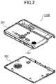
- FIG. 2 is a diagram depicting an example configuration of a chassis of the conference apparatus according to the embodiment.
- the chassis 1100 of the conference device 10 has, for example, a chassis upper cover 201 (first chassis) and a chassis lower cover 202 (second chassis) which can be separated in the thickness direction from each other.
- the sound pickup hole 1131 On the chassis upper cover 201, the sound pickup hole 1131, described as above, is provided.
- a material of the chassis 1100 for example, a hard resin or the like, such as a plastic, is used.
- the chassis 1100 may be separated into not two but three or more pieces.
- FIG. 3 is a perspective view depicting a holding structure for a microphone according to the embodiment.
- a holding structure of the microphone according to the embodiment includes a microphone 301, a microphone rubber 302 (elastic member) arranged around the microphone 301, and a microphone holder 303 (retention member) retaining the microphone 301 and the microphone rubber 302.
- the microphone 301 is a device converting a picked up sound into an electric signal.
- the microphone 301 has a shape of, for example, an approximately cylindrical form, and picks up voice/sound from the front, to output a voice signal converted into an electric signal from the rear surface by a cable or the like.
- the microphone rubber 302 is an elastic member formed of an elastic material such as a silicone rubber or a butyl rubber, for example.
- the microphone rubber 302 includes a holding unit 309 for retaining the microphone 301 and a flange portion (attachment portion) 310 arranged around the holding unit 309.
- FIGs. 4A through 4D are diagrams depicting an example of a microphone rubber according to the embodiment.
- FIG. 4A is a top view of the microphone rubber 302.
- FIG. 4B is a side view
- FIG. 4C is a bottom view.
- FIG. 4D is a cross-sectional view cut along A-A in FIG. 4A .
- the holding unit 309 of the microphone rubber 302 is formed, for example, so as to cover the microphone 301.
- an opening 401 for picking up sound is provided, and on a lower face a hole 402 for drawing out a cable is provided.
- an inner wall of the holding unit 309 is formed, for example, approximately in contact with a periphery of the microphone 301, and retains the microphone 301.
- FIGs. 4A through 4D illustrate a configuration that retains the microphone 301 by the entire inner wall of the holding unit 309.
- the configuration is an example.
- the configuration may be, for example, forming a plurality of projection portions on the inner wall of the holding unit 309 and retaining the microphone 301 by the projection portions or the like.
- the opening 401 is expanded using the elasticity of the microphone rubber 302, and the microphone 301 can be engaged with the holding unit 309 of the microphone rubber 302.
- the flange portion 310 of the microphone rubber 302 is arranged around the holding unit 309, as illustrated in FIGs. 4A through 4D , and is an attachment portion projected from the holding unit 309.
- the elastic member used for the microphone rubber 302 preferably exhibits low transmissibility upon resonance (resonance magnification) occurring. That is, the greater the loss factor of a material is, the higher the vibration insulation effect is. Moreover, a resonance point can be adjusted depending on hardness of the material of the microphone rubber 302. When the hardness of the material is low, the resonance point (resonance frequency) is low, and when the hardness is great, the resonance point is great.
- the resonance point of the microphone rubber 302 is preferably different from frequency of an excitation source (oscillation source).
- the excitation source is a speaker
- the reproduction frequency is, for example, 300 Hz through 12000 Hz, which is a wide bandwidth. Therefore, setting the resonance frequency of the microphone rubber 302 outside the reproduction frequency of the speaker is difficult.
- the resonance frequency of the microphone rubber 302 is preferably less than 300 Hz or greater than 12000 Hz.
- the microphone rubber resonates, in a case of employing a material having a great loss factor, because the resonance magnification is small, and propagation of oscillation from the chassis can be suppressed.
- the microphone holder 303 is a retention member for retaining the flange portion 310 of the microphone rubber 302 that retains the microphone 301 at a predetermined position of the chassis 1100, and thereby retaining the microphone 301 in a floating state.
- the microphone holder 303 is formed of, for example, a material having elasticity, a plastic or the like.
- the microphone holder 303 may hold the flange portion 310 between the chassis 1100 and the microphone holder 303 in a state of being attached to the chassis 1100, and thereby retaining the flange portion 310 at a predetermined position of the chassis 1100.
- the flange portion 310 is projected from the holding unit 309, and the flange portion 310 that is the projected portion may be held between the chassis 1100 and the microphone holder 303, and thereby the flange portion 310 is retained at a predetermined position of the chassis 110.
- the microphone holder 303 is formed so as to cover the microphone rubber 302 on the side surface 304 and on the rear surface 305. Therefore, transmission of noise by a fan or the like inside the chassis 1100 to the microphone 301 is reduced. Moreover, the microphone holder 303 includes an attachment shaft 306, a cable drawing out unit 307, claw portions 308a, 308b, a notch unit 311 for positioning, or the like. Upon assembling, for example, after the microphone 301 is placed in the microphone rubber 302, the microphone rubber 302 is put on the microphone holder 303. Then, the microphone holder 303 is attached to the chassis upper cover 201.
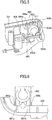
- FIG. 5 is a diagram depicting an example attachment of the microphone holder to the chassis upper cover according to the embodiment.
- the chassis upper cover 201 includes bearing portions 502a, 502b for supporting the attachment shaft 306 of the microphone holder 303, a projection portion 503 for positioning the microphone holder 303, first rib portions 504a, 504b arranged corresponding to the claw portions 308a, 308b, or the like.
- the microphone holder 303 is rotatable around the attachment shaft 306, with respect to the chassis upper cover 201.
- the attachment shaft 306 is engaged with the bearing portions 502a, 502b of the chassis upper cover 201.
- the microphone holder 303 is rotated around the attachment shaft 306 toward the right side wall 1130, and the claw parts 308a, 308b of the microphone holder 303 are locked at the rib portions 504a, 504b.
- the notch 311 for positioning the microphone holder 303 is fitted to the projection portion 503 for positioning the chassis upper cover 201, and thereby enhancing accuracy of attachment position of the microphone 301 and the microphone holder 303. Moreover, in the embodiment, because the microphone holder 303 is attached to the chassis upper cover 201 by the claw portions 308a, 308b, screw clamping becomes unnecessary, and a configuration where attachment and detachment for the microphone 301 within a limited space is easy can be provided.
- a cable harness that outputs sound signals from the microphone 301 can be drawn through the hole for cable drawing 402 of the microphone rubber 302 and the cable drawing unit 307 of the microphone holder 303.
- FIG. 6 is a diagram depicting a relation between the chassis lower cover and the microphone holder according to the embodiment.
- a structure is provided, in which after the microphone holder 303, on which the microphone 301 and the microphone rubber 302 are mounted, is attached to the chassis upper cover 201, as illustrated in FIG. 5 , the chassis lower cover is closed (attached).
- the chassis upper cover 201 may be placed with the opening 401 facing upward so that the chassis lower cover 202 is attached from above, or the chassis upper cover 201 may be attached on the chassis lower cover 202.
- the chassis lower cover 202 is provided with second rib portions 601a, 601b for fixing the microphone holder 303 arranged so as to contact the inside of the claw portions 308a, 308b of the microphone holder 303 when the chassis lower cover 202 is closed. Accordingly, a structure in which when the chassis lower cover 202 is closed, the claw portions 308a, 308b of the microphone holder 303 open outward by the second rib portions 601a, 601b, is provided. Moreover, on upper faces of the second rib portions 601a, 601b of the chassis lower cover 202, for example, inclined surfaces facing outward are provided, as illustrated in FIG. 6 . Accordingly, the second rib portions 601a, 601b smoothly contact the inside of the claw portions 308a, 308b of the microphone holder 303.
- FIGs. 7A and 7B are diagrams for explaining a fixation of the microphone holder by the chassis lower cover according to the embodiment.
- FIG. 7A depicts a state of the claw portion 308b of the microphone holder 303 and the second rib portion 601b of the chassis lower cover 202 before the chassis lower cover 202 is closed (state of FIG. 5 ).
- FIG. 7B depicts a state of the claw portion 308b of the microphone holder 303 and the second rib portion 601b of the chassis lower cover 202 after the chassis lower cover 202 is closed from the state of FIG. 5 .
- the second rib portion 601b of the chassis lower cover 202 contacts the inside (right side in FIG. 7 ) of the claw portion 308b for fixing the microphone holder 303, and presses the claw portion 308b toward the side of the first rib portion 504b of the chassis upper cover 201.
- the claw portions 308a, 308b are pressed against the rib portions 504a, 504b of the chassis upper cover 201, and thereby the microphone holder 303 is fixed to the chassis upper cover 201 (chassis 1100).
- the chassis lower cover 202 is closed, according to elastic force of the claw portions 308a, 308b of the microphone holder 303, the microphone holder 303 is tightly and accurately fixed to the chassis upper cover 201.
- the claw portion 308b of the microphone holder 303 is restored from the state of FIG. 7B to the state of FIG. 7A , and becomes a state where the microphone holder 303 can be detached. Therefore, according to the embodiment, not only attachment of the microphone 301, but also detachment or replacement of the microphone 301 can be performed easily.
- FIG. 8 is a cross-sectional view of a holding structure of the microphone according to the embodiment.
- FIG. 8 is a cross-sectional view of a state where after the microphone 301, the microphone rubber 302 and the microphone holder 303 are attached to the chassis upper cover 201, the chassis lower cover 202 is closed.
- a boss portion is arranged in a circular shape about the sound pickup hole 1131 so as to contact the flange portion of the microphone rubber 302.
- the boss portion 801 arranged in a circular shape is an example, and the boss portion 801 has a shape depending on an attachment portion of the microphone rubber 302 (flange portion 310 or the like).
- the microphone 301 is supported by the holding unit 309 of the microphone rubber 302. Moreover, the microphone rubber 302 is retained at a predetermined position of the chassis 1100 (See FIG. 1 ) by the flange portion 310 of the microphone rubber 302 held between the microphone holder 303 and the boss portion 801 arranged on the chassis upper cover 201 so as to be opposed to the microphone holder 303.
- the flange portion 310 of the microphone rubber 302 is fixed to the chassis 1100 (chassis upper cover 201), but the holding unit 309 is not directly fixed to the chassis 1100. Moreover, a predetermined gap is provided between the holding unit 309 of the microphone rubber 302 and the microphone holder 303 and the chassis 1100, and thereby a floating structure of the microphone 301 is enabled, and propagation of vibration from the chassis 1100 to the microphone 301 is reduced.
- a gap is provided between a portion other than the flange portion 310 of the microphone rubber 302 (holding unit 309 or the like) and the microphone holder 303 and the chassis 1100.
- the portion other than the flange portion 310 of the microphone rubber 302 may have a part that contacts the microphone holder 303 or the chassis 1100, if the portion other than the flange portion 310 of the microphone rubber 302 is substantially in a floating state with respect to the microphone holder 303 and the chassis 1100.
- the rear surface portion 305 of the microphone holder 303 serves as a wall, and reduces noise reaching the microphone 301 from inside the chassis 1100.
- FIG. 9 is a diagram depicting a position of a rib for fixing a holder of the chassis lower cover according to the embodiment.
- the second rib portions for fixing the microphone holder 303 are arranged.
- FIG. 10 is an enlarged view of the rib for fixing holder of the chassis lower cover according to the embodiment. As illustrated in FIG. 10 , in the area 901 of the chassis lower cover 202, the second rib portions 601a, 601b for fixing the microphone holder 303 are provided.
- FIG. 11 is a diagram depicting an example of a rib for fixing a holder of the chassis lower cover according to the embodiment.
- the chassis lower cover 202 is closed with respect to the microphone holder 303 attached to the chassis upper cover 201
- the second rib portions 601a, 601b of the chassis lower cover 202 contact the inside of the claw portions 308a, 308b of the microphone holder 303, respectively.
- the claw portions 308a, 308b of the microphone holder 303 open outward, and the microphone holder 303 is fixed to the chassis upper cover 201 tightly and accurately.
- the chassis lower cover 202 according to the embodiment only has to be provided with the second rib portions 601a, 601b inside thereof, and thereby the microphone holder 303 can be fixed to the chassis 1100 (chassis upper cover 201) without increasing the number of parts or without increasing the cost substantially.
- the flange portion 310 of the microphone rubber 302 according to the embodiment is an example of the attachment portion.
- the microphone rubber 302 illustrated in FIG. 4 is employed.
- the attachment portion of the microphone rubber 302 may have another shape.
- the holding unit 309 of the microphone rubber 302 suppressing effect for propagation of vibration becomes higher as a contact area with the chassis 1100 is reduced.
- a central portion of the sound pickup hole 1131 arranged in the chassis 1100 and a central portion of the microphone 301 accurately coincide with each other.
- the attachment portion of the microphone rubber 302 may have a shape that retains the holding unit 309 at three points so as to satisfy the above-described two conditions.
- the embodiment is described that after the microphone holder 303 is attached to the chassis upper cover 201, the chassis lower cover 202 is attached.
- the embodiment does not restrict the range of the present invention.
- the chassis lower cover 202 has a sound pickup hole 1131, and after the microphone holder 303 is attached to the chassis lower cover 202, the chassis upper cover 201, which is provided with the second rib portions 601a, 601b, is attached.
- FIG. 12 is a diagram depicting an example of a shape of a boss portion according to the embodiment.
- the boss portion 801 is arranged on the inner wall of the chassis upper cover 201, for example, in a circular shape about the sound pickup hole 1131 so as to contact the flange portion 310 of the microphone rubber 302. Accordingly, the boss portion 801, opposed to the microphone holder 303, can retain the flange portion 310 of the microphone rubber 302.
- the boss portion 801 has, for example, a circular shape about the sound pickup hole 1131 is explained.
- the boss portion 801 with a circular shape is an example, and the boss portion 801 may have a shape of, for example, an ellipse, a polygon or the like depending on a shape of the microphone rubber 302.
- FIG. 13 is a diagram depicting an example of a microphone rubber arranged at the boss portion according to the embodiment.
- the shape of the boss portion 801 corresponds to a shape of the flange portion 310 of the microphone rubber 302. Therefore, the boss portion 801 illustrated in FIG. 12 is configured so as to contact the flange portion 310 of the microphone rubber 302 over the entire circumference.
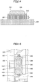
- FIG. 14 is a diagram of the boss portion viewed from a side surface according to the embodiment.
- the boss portion 801 has a predetermined height "h" with respect to the inner wall of the chassis upper cover 201, and is arranged so as to contact the flange portion 310 of the microphone rubber 302.
- FIG. 15 is a cross-sectional view depicting a space anterior to the microphone according to the embodiment.
- the microphone rubber 302 is retained by the microphone holder 303 and the chassis lower cover 202 is closed, spaces (gaps) appear anterior to and posterior to the microphone 301, as illustrated in FIG. 15 .
- spaces anterior to and posterior to the microphone 301 a floating structure for the microphone 301 is enabled.
- the space 1501 appearing anterior to the microphone 301 and space inside the chassis are sealed by the boss portion 801 and the flange portion 30 of the microphone rubber. Therefore, in the embodiment, there is an effect that noise generated inside the chassis (e.g. sound from the cooling fan) and picked up by the microphone 301 is reduced.
- the space 1501 appearing anterior to the microphone 301 and the space inside the chassis are sealed, and thereby the space 1501 has an opening (sound pickup hole 1131).
- resonance Helmholtz resonance
- FIG. 16 is a diagram depicting an example of the frequency characteristic of the microphone according to the embodiment.
- FIG. 16 illustrates an example of the frequency characteristic when the microphone 301 is not incorporated in the chassis.
- the frequency characteristic of the microphone 301 is preferably as flat as possible so that voice sound uttered by a user can be transmitted correctly to a conference apparatus of the communication destination.
- the frequency characteristic 1601 of the microphone 301 preferably falls between a template indicating an upper limit of the frequency characteristic 1602 and a template indicating a lower limit of the frequency characteristic 1603.
- FIG. 17 is a diagram depicting an example of change in the frequency characteristic due to the space anterior to the microphone according to the embodiment.
- FIG. 17 illustrates an example of a case where the microphone 301 is incorporated in the chassis as illustrated in FIG. 15 , and thereby resonance (sympathetic vibration) occurs in the space 1501 anterior to the microphone 301, and a peak appears at around 8 to 10 kHz.
- the frequency characteristic of the microphone 301 does not fall between the template indicating the upper limit 1602 and the template indicating the lower limit 1603.
- a notch is provided in the boss portion 801, and thereby the sealing structure between the space 1501 anterior to the microphone 301 and the space inside the chassis is eliminated and the resonance is prevented.
- FIG. 18 is a diagram depicting an example of a notch in a boss portion according to a first embodiment.
- a part of the boss portion 801 is removed to provide a notch (open portion) 1801.
- the configuration illustrated in FIG. 18 is an example, and a number of notches may be two or more.
- FIG. 19 is a diagram of the boss portion viewed from a side surface according to the first embodiment.
- air can move freely between the space 1501 anterior to the microphone 301 and the space inside the chassis. Because Helmholtz resonance in which air in a space having an opening plays a role as a spring and resonates, by causing air in the space 1501 to move freely, the resonance can be prevented.
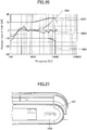
- FIG. 20 is a diagram depicting an example of change in frequency characteristic due to the notch according to the first embodiment.
- the frequency characteristic 2001 in the case where there is not a notch in the boss portion 801
- the frequency characteristic 2002 in the case where there is a notch 1801 in the boss portion 801
- the peak due to the resonance is eliminated.
- the space 1501 anterior to the microphone 301 and the space inside the chassis are not sealed, so the microphone 301 may be easily affected by noise from a cooling fan, a speaker or the like. Therefore, in the embodiment, a partition is preferably provided between the space 1505 anterior to the microphone 301 and the fan, speaker or the like inside the chassis to perform sound insulation.
- noise of the fan may be removed by a noise canceller or the like.
- the boss portion is provided with a notch, and thereby resonance in the space 1501 anterior to the microphone 301 is prevented and an influence on the frequency characteristic of the microphone 301 can be prevented.
- the opening (sound pickup hole 1131) anterior to the microphone 301 is changed, and thereby the resonance (sympathetic vibration) frequency of the space 1501 anterior to the microphone 301 is moved, for example, to the outside of the frequency band used in electronic devices such as the conference apparatus 10.
- the resonance (sympathetic vibration) frequency of the space 1501 anterior to the microphone 301 can be expressed by the following formula (mathematical expression for Helmholtz resonance)
- f corresponds to resonance frequency
- c corresponds to a sound velocity
- S corresponds to an opening area of the opening (sound pickup hole 1131)
- V corresponds to a volume of inside (space 1501)
- L corresponds to a length of the opening (sound pickup hole 1131).
- the resonance frequency f is found to be able to be increased, for example, by increasing the area of the opening of the sound pickup hole 1131.
- FIG. 21 is a diagram depicting an example of a sound pickup hole according to a second embodiment.
- the sound pickup hole 1131 is a through hole arranged approximately at a center of a circumference corresponding to the boss portion 801 and having a predetermined inner diameter (e.g. 1.5 mm). For example, by changing the inner diameter of the sound pickup hole 1131, the resonance frequency of the space 1501 can be changed.
- FIG. 22 is a diagram depicting another example of the sound pickup hole according to the second embodiment.
- the inner diameter of the sound pickup hole 1131 is not changed, but additional sound pickup holes 2201, 2202 are provided, and thereby the opening area S of the opening of the space 1501 is substantially increased.
- the number of the additional sound pickup holes 2201, 2202 is an example, and may be another number.
- the inner diameter of the additional sound pickup holes 2201, 2202 may not be the same as the sound pickup hole 1131.
- FIG. 23 is a diagram depicting a variation of the sound pickup hole according to the second embodiment.
- the inner diameter of the sound pickup hole 1131 is increased (e.g. 2 mm), and moreover, additional sound pickup holes 2201, 2202 are provided, and thereby the change in the resonance frequency becomes greater than the example of FIG. 22 .
- the inner diameter of the additional sound pickup holes 2201, 2202 is the same as the sound pickup hole 1131.
- the inner diameter of the additional sound pickup holes 2201, 2202 may be different from the inner diameter of the sound pickup hole 1131.
- the number of the additional sound pickup holes 2201, 2202 may be another number.
- the explanation is made assuming that the openings of the sound pickup hole 1131 and the additional sound pickup holes 2201, 2202 have circular shapes. But, the shape does not restrict the scope of the invention.
- the openings of the sound pickup hole 1131 and the additional sound pickup holes 2201, 2202 may have a shape of an ellipse, a polygon or the like.
- the explanation is made assuming the inner diameter is changed. However, the area of the openings may be changed by changing sizes other than the inner diameter (e.g. a longitudinal length, a transverse length, or an aspect ratio).
- the resonance frequency of the space 1501 anterior to the microphone 301 is changed, and thereby the influence on the frequency characteristic of the microphone 301 can be reduced.
- the chassis anterior to the microphone 301 is made thinner or the length of the sound pickup hole 1131 is made shorter, and thereby the resonance (sympathetic vibration) frequency of the space 1501 anterior to the microphone 301 is moved to the outside of the frequency band used in electronic devices such as the conference apparatus 10.
- the resonance frequency by the space 1501 is found to be able to be made greater by shortening the length L of the sound pickup hole 1131.
- FIGs. 24A and 24B are diagrams for explaining a difference in a length of a sound pickup hole according to a third embodiment.
- FIG. 24A depicts a state before taking measures.
- the thickness of the chassis anterior to the microphone 301 is assumed to be t1 (e.g. 2 mm).
- FIG. 24B depicts a state after taking measures according to the embodiment.
- the thickness of the chassis anterior to the microphone 301 is assumed to be t2 (e.g. 1.5 mm), which is thinner than the chassis in FIG. 24A .
- the length of the sound pickup hole 1131 in FIG. 24B is less than the length of the sound pickup hole 1131 in FIG. 24A . In this way, by changing the thickness of the chassis anterior to the microphone 301, the resonance frequency of the space 1501 can be changed.
- the thickness of the chassis anterior to the microphone 301 is reduced.
- only a part around the sound pickup hole 1131 may be made thinner.
- the resonance frequency of the space 1501 anterior to the microphone 301 can be changed without increasing the area of the opening of the sound pickup hole 1131 and the number of the sound pickup holes, and the influence on the frequency characteristic of the microphone 301 can be reduced.
- the resonance frequency of the space 1501 is found to be able to be changed also by changing the volume V of the space 1501.
- the volume of the space 1501 can be changed.
- the above-described changes of the area S of the opening of the space 1501, the length L of the opening, and the volume V can be implemented in arbitrary combination.
- the frequency characteristic of the microphone 301 due to the resonance of the space 1501 can be brought close to flat.
- the frequency before adjustment is preferably close to flat.
- the microphone holding structure includes a holding unit 309 formed of an elastic material for holding a microphone 301; and an elastic member (microphone rubber 302) having an attachment portion (flange portion 310) arranged around the holding unit 309.
- the microphone holding structure includes a retention member (microphone holder 303) for retaining the attachment portion (flange portion 310) at a predetermined position (boss portion 801) of a first chassis (chassis upper cover 201).
- the microphone holding structure includes a second chassis (chassis lower cover 202) for fixing the retention member (microphone holder 303) to the first chassis (chassis upper cover 201).
- a floating structure for the microphone 301 is enabled only by the microphone rubber 302, the microphone holder 303 and chassis 1100 (chassis upper cover 201, chassis lower cover 202).
- the microphone holding structure in which a microphone can be easily incorporated into a limited space of an electronic device or the like with a low cost while preventing a vibration from propagating from the chassis to the microphone can be provided.
- the microphone holding structure in which a microphone is attachable/detachable in a limited space of an electronic device or the like with a low cost while preventing a vibration from propagation from the chassis to the microphone can be provided.
- the microphone 301 is sealed on the side surface and the rear surface by the microphone rubber 302 and the microphone holder 303 according to the above-described microphone holding structure, sound pickup of noise occurring inside the chassis, such as a fan, can be reduced.
Landscapes
- Engineering & Computer Science (AREA)
- Signal Processing (AREA)
- Health & Medical Sciences (AREA)
- Otolaryngology (AREA)
- Physics & Mathematics (AREA)
- Acoustics & Sound (AREA)
- Telephone Set Structure (AREA)
- Details Of Audible-Bandwidth Transducers (AREA)
Abstract
Description
- 0001 The disclosures herein generally relate to holding structure of a microphone and an electronic device.
- 0002 A conference system for conducting a remote conference with a remote location via a communication network such as the Internet is popular. In such a conference system, for example, images or voices of participants or the like of the remote conference are acquired by terminal devices for conference, converted into digital data, and sent to a terminal device of a communication destination. The terminal device of the communication destination displays the image of the participant that is received and outputs the voice of the participant. Such processes are performed bi-directionally, and thereby, the participants of the remote conference can conduct a video conference with the remote location in a state near an actual conference.
- 0003 For example, when a speaker and a microphone are installed in a small-sized chassis of a terminal device used in such a conference system, there is a problem that a vibration of the speaker due to the sound output propagates to the chassis of the terminal device, and furthermore the vibration propagates from the chassis to the microphone. When the terminal device has an echo canceller, in a usual case, even if a voice reproduced from a speaker is input into a microphone, according to the function of the echo canceller, an echo component is removed. However, when the microphone picks up a vibration of the chassis, as described above, a distorted reproduction sound from the speaker is input to the microphone. That is, a path for transmitting voice from the speaker to the microphone is non-linear, and an echo may not be removed sufficiently.
- 0004 As a technique for suppressing such propagation of a vibration of the chassis to the microphone, a technique of holding the microphone in a floating state is known. For example, a holding structure for microphone is known, in which a microphone is held in a floating state using a magnetic force to block an environmental vibration or noise (See, for example, Patent document 1). Moreover, an electronic device in which a microphone is elastically supported inside a cabinet, a rear side of the microphone is covered with a back cover formed of a rubber-like elastic body, and the back cover is fixed to the cabinet using a fixation screw is known (See, for example, Patent document 2). Furthermore, an attachment mechanism for microphone having an elastic member for covering a side face of a microphone with an approximately cylindrical shape and a retention member for retaining the microphone by engaging with the elastic member is known (See, for example, Patent document 3).
- 0005 The technique disclosed in Patent document 1 is a floating structure using a magnetic force, and has a problem of low incorporating property and high cost. Moreover, the technique disclosed in Patent document 2 requires screwing from the rear side, and incorporating or replacing a microphone within a limited space of a small electronic device or the like is quite difficult. Moreover, in the technique disclosed in Patent document 3, because a contact area of a microphone and a chassis via an elastic member is great, suppressing the propagation of vibration from a chassis to the microphone is difficult.
- 0006 In this way, in the conventional technique, incorporating a microphone in a limited space of an electronic device or the like, at low cost, while preventing a vibration from propagating from a chassis to the microphone is quite difficult.
- 0007 In view of the above, providing a holding structure for a microphone, in which incorporating the microphone in a limited space of an electronic device or the like at low cost, while preventing a vibration from propagating from a chassis to the microphone is easy, is desirable.
- 0008 According to an embodiment, a holding structure for holding a microphone includes a chassis configured to be separated into at least a first chassis and a second chassis; an elastic member formed of an elastic material and having a holding unit configured to hold the microphone and an attachment portion provided in a periphery of the holding unit; a retention member configured to retain the attachment portion at a predetermined position of the first chassis; and the second chassis configured to fix the retention member to the first chassis, the retention member being fixed to the first chassis by the second chassis in a state where the second chassis is attached to the first chassis.
- 0009 According to at least one embodiment, a holding structure for a microphone is provided, in which incorporating the microphone in a limited space of an electronic device or the like at low cost, while preventing a vibration from propagating from a chassis to the microphone, is easy.
- 0010
- [
FIG. 1 ]
FIG. 1 is an external view depicting a conference apparatus according to an embodiment. - [
FIG. 2 ]
FIG. 2 is a diagram depicting an example configuration of a chassis of the conference apparatus according to the embodiment. - [
FIG. 3 ]
FIG. 3 is a perspective view depicting a holding structure for a microphone according to the embodiment. - [
FIG. 4A ]
FIG. 4A is a diagram depicting an example of a microphone rubber according to the embodiment. - [
FIG. 4B ]
FIG. 4B is a diagram depicting an example of the microphone rubber according to the embodiment. - [
FIG. 4C ]
FIG. 4C is a diagram depicting an example of the microphone rubber according to the embodiment. - [
FIG. 4D ]
FIG. 4D is a diagram depicting an example of the microphone rubber according to the embodiment. - [
FIG. 5 ]
FIG. 5 is a diagram depicting an example attachment of a microphone holder to a chassis upper cover according to the embodiment. - [
FIG. 6 ]
FIG. 6 is a diagram depicting a relation between a chassis lower cover and the microphone holder according to the embodiment. - [
FIG. 7A ]
FIG. 7A is a diagram for explaining a fixation of the microphone holder by the chassis lower cover according to the embodiment. - [
FIG. 7B ]
FIG. 7B is a diagram for explaining the fixation of the microphone holder by the chassis lower cover according to the embodiment. - [
FIG. 8 ]
FIG. 8 is a cross-sectional view of a holding structure of the microphone according to the embodiment. - [
FIG. 9 ]
FIG. 9 is a diagram depicting a position of a rib for fixing holder of the chassis lower cover according to the embodiment. - [
FIG. 10 ]
FIG. 10 is an enlarged view of the position of the rib for fixing holder of the chassis lower cover according to the embodiment. - [
FIG. 11 ]
FIG. 11 is a diagram depicting an example of a rib for fixing holder according to the embodiment. - [
FIG. 12 ]
FIG. 12 is a diagram depicting an example of a shape of a boss portion according to the embodiment. - [
FIG. 13 ]
FIG. 13 is a diagram depicting an example of a microphone rubber arranged at the boss portion according to the embodiment. - [
FIG. 14 ]
FIG. 14 is a diagram of the boss portion viewed from a side surface according to the embodiment. - [
FIG. 15 ]
FIG. 15 is a cross-sectional view depicting a space anterior to the microphone according to the embodiment. - [
FIG. 16 ]
FIG. 16 is a diagram depicting an example of frequency characteristic of the microphone according to the embodiment. - [
FIG. 17 ]
FIG. 17 is a diagram depicting an example of change in the frequency characteristic due to the space anterior to the microphone according to the embodiment. - [
FIG. 18 ]
FIG. 18 is a diagram depicting an example of a notch of a boss portion according to a first embodiment. - [
FIG. 19 ]
FIG. 19 is a diagram of the boss portion viewed from a side surface according to the first embodiment. - [
FIG. 20 ]
FIG. 20 is a diagram depicting an example of change in frequency characteristic due to the notch according to the first embodiment. - [
FIG. 21 ]
FIG. 21 is a diagram depicting an example of a sound pickup hole according to a second embodiment. - [
FIG. 22 ]
FIG. 22 is a diagram depicting another example of the sound pickup hole according to the second embodiment. - [
FIG. 23 ]
FIG. 23 is a diagram depicting a variation of the sound pickup hole according to the second embodiment. - [
FIG. 24A ]
FIG. 24A is a diagram for explaining a difference in a length of a sound pickup hole according to a third embodiment. - [
FIG. 24B ]
FIG. 24B is a diagram for explaining the difference in the length of the sound pickup hole according to the third embodiment. - 0011 In the following, embodiments of the present invention will be described with reference to the accompanying drawings.
- 0012
-
FIG. 1 is an external view depicting a conference apparatus according to an embodiment. Theconference apparatus 10 illustrated inFIG. 1 is an example of electronic devices disclosed in the present application, and is a terminal device used in a remote conference system. The electronic devices disclosed in the present application include various electronic devices provided with a microphone in a chassis, such as a mobile phone apparatus, a telephone apparatus, an intercom apparatus, a picture recorder, and an imaging device, for example. - 0013 In
FIG. 1 , theconference apparatus 10 includes achassis 1100, anarm 1200 and acamera housing 1300. Among them, afront side wall 1110 of thechassis 1100 has an inlet face (not illustrated) including a plurality of inlet holes, and arear side wall 1120 of thechassis 1100 has anexhaust face 1121 on which a plurality of exhaust holes are formed. Accordingly, by driving a cooling fan included in thechassis 1100, air anterior to theconference apparatus 10 can be taken in via the inlet face (not illustrated) and exhausted to the rear of theconference apparatus 10 via theexhaust face 1121. On a right-side wall 1130 of the chassis 1100 asound pickup hole 1131 is formed, and a microphone incorporated in thechassis 1100 is capable of picking up an ambient sound, such as voice or sound. - 0014 An
operation panel 1150 is formed toward the right-side wall 1130 on an upper face of thechassis 1100. Theoperation panel 1150 is provided with a plurality of operation buttons (108a through 108e), apower switch 109, analarm lamp 119, and the like. Moreover, theoperation panel 1150 is also provided with asound output face 1151, which is formed of a plurality of sound output holes for allowing output sound from a built-in speaker 115 to pass through. In addition, anaccommodation portion 1160 serving as a recess for accommodating thearm 1200 and thecamera housing 1300 is formed toward a left-side wall 1140 on the upper face of thechassis 1100. - 0015 A plurality of connection ports (1132a through 1132c) for connecting cables, such as a wired LAN (Local Area Network) or a USB (Universal Serial Bus) are provided on the right-
side wall 1130 of thechassis 1100. In contrast, a connection port (not illustrated) for connecting a cable for a display device is provided toward the left-side wall 1140 of thechassis 1100. - 0016 Next, the
arm 1200 is attached to thechassis 1100 via atorque hinge 1210 and is configured to be rotatable in the vertical direction within a range of a tilt angle θ1 of 135 degrees with respect to thechassis 1100.FIG. 1 indicates a state in which the tilt angle θ1 is 90 degrees. - 0017 The
camera housing 1300 is provided with a built-incamera 1021, and can capture an image of a user, a document, a room, or the like. In addition, thecamera housing 1300 has atorque hinge 1310. Thecamera housing 1300 is attached to thearm 1200 via thetorque hinge 1310. Thecamera housing 1300 is attached to thearm 1200 via thetorque hinge 1310. Moreover, thecamera housing 1300 is configured to be rotatable in the vertical and horizontal directions within a range of a pan angle θ2 of from 180 degrees to +180 degrees and a tilt angle θ3 of from -45 degrees to +45 degrees with respect to thearm 1200, where the state illustrated inFIG. 1 is 0 degrees. - 0018 The above-described
sound pickup hole 1131, the sound output face, the plurality of operation buttons (108a through 108e), thepower switch 109 of the like can be arranged at an arbitrary position on thechassis 1100. Moreover, ranges of motion of the tilt angle θ1, the pan angle θ2, and the tilt angle θ3 are an example. The ranges of motion can be arbitrarily set. - 0019
FIG. 2 is a diagram depicting an example configuration of a chassis of the conference apparatus according to the embodiment. As illustrated inFIG. 2 , thechassis 1100 of theconference device 10 has, for example, a chassis upper cover 201 (first chassis) and a chassis lower cover 202 (second chassis) which can be separated in the thickness direction from each other. On the chassisupper cover 201, thesound pickup hole 1131, described as above, is provided. As a material of thechassis 1100, for example, a hard resin or the like, such as a plastic, is used. In addition, thechassis 1100 may be separated into not two but three or more pieces. - 0020
-
FIG. 3 is a perspective view depicting a holding structure for a microphone according to the embodiment. A holding structure of the microphone according to the embodiment includes amicrophone 301, a microphone rubber 302 (elastic member) arranged around themicrophone 301, and a microphone holder 303 (retention member) retaining themicrophone 301 and themicrophone rubber 302. - 0021 The
microphone 301 is a device converting a picked up sound into an electric signal. Themicrophone 301 has a shape of, for example, an approximately cylindrical form, and picks up voice/sound from the front, to output a voice signal converted into an electric signal from the rear surface by a cable or the like. - 0022 The
microphone rubber 302 is an elastic member formed of an elastic material such as a silicone rubber or a butyl rubber, for example. Themicrophone rubber 302 includes a holdingunit 309 for retaining themicrophone 301 and a flange portion (attachment portion) 310 arranged around the holdingunit 309. - 0023
FIGs. 4A through 4D are diagrams depicting an example of a microphone rubber according to the embodiment.FIG. 4A is a top view of themicrophone rubber 302.FIG. 4B is a side view, andFIG. 4C is a bottom view.FIG. 4D is a cross-sectional view cut along A-A inFIG. 4A . - 0024 The holding
unit 309 of themicrophone rubber 302 is formed, for example, so as to cover themicrophone 301. On an upper face of the holdingunit 309 anopening 401 for picking up sound is provided, and on a lower face ahole 402 for drawing out a cable is provided. Moreover, an inner wall of the holdingunit 309 is formed, for example, approximately in contact with a periphery of themicrophone 301, and retains themicrophone 301.FIGs. 4A through 4D illustrate a configuration that retains themicrophone 301 by the entire inner wall of the holdingunit 309. However, the configuration is an example. The configuration may be, for example, forming a plurality of projection portions on the inner wall of the holdingunit 309 and retaining themicrophone 301 by the projection portions or the like. - 0025 When the
microphone 301 is incorporated into themicrophone rubber 302, theopening 401 is expanded using the elasticity of themicrophone rubber 302, and themicrophone 301 can be engaged with the holdingunit 309 of themicrophone rubber 302. - 0026 The
flange portion 310 of themicrophone rubber 302 is arranged around the holdingunit 309, as illustrated inFIGs. 4A through 4D , and is an attachment portion projected from the holdingunit 309. - 0027 The elastic member used for the
microphone rubber 302 preferably exhibits low transmissibility upon resonance (resonance magnification) occurring. That is, the greater the loss factor of a material is, the higher the vibration insulation effect is. Moreover, a resonance point can be adjusted depending on hardness of the material of themicrophone rubber 302. When the hardness of the material is low, the resonance point (resonance frequency) is low, and when the hardness is great, the resonance point is great. - 0028 The resonance point of the
microphone rubber 302 is preferably different from frequency of an excitation source (oscillation source). For example, in theconference apparatus 10, the excitation source is a speaker, and the reproduction frequency is, for example, 300 Hz through 12000 Hz, which is a wide bandwidth. Therefore, setting the resonance frequency of themicrophone rubber 302 outside the reproduction frequency of the speaker is difficult. However, if possible, the resonance frequency of themicrophone rubber 302 is preferably less than 300 Hz or greater than 12000 Hz. However, even when the microphone rubber resonates, in a case of employing a material having a great loss factor, because the resonance magnification is small, and propagation of oscillation from the chassis can be suppressed. - 0029 Here, returning to
FIG. 3 , the explanation for the holding structure of the microphone will be continued. - 0030 The
microphone holder 303 is a retention member for retaining theflange portion 310 of themicrophone rubber 302 that retains themicrophone 301 at a predetermined position of thechassis 1100, and thereby retaining themicrophone 301 in a floating state. Themicrophone holder 303 is formed of, for example, a material having elasticity, a plastic or the like. Themicrophone holder 303 may hold theflange portion 310 between thechassis 1100 and themicrophone holder 303 in a state of being attached to thechassis 1100, and thereby retaining theflange portion 310 at a predetermined position of thechassis 1100. Theflange portion 310 is projected from the holdingunit 309, and theflange portion 310 that is the projected portion may be held between thechassis 1100 and themicrophone holder 303, and thereby theflange portion 310 is retained at a predetermined position of the chassis 110. - 0031 The
microphone holder 303 is formed so as to cover themicrophone rubber 302 on theside surface 304 and on therear surface 305. Therefore, transmission of noise by a fan or the like inside thechassis 1100 to themicrophone 301 is reduced. Moreover, themicrophone holder 303 includes anattachment shaft 306, a cable drawing outunit 307,claw portions notch unit 311 for positioning, or the like. Upon assembling, for example, after themicrophone 301 is placed in themicrophone rubber 302, themicrophone rubber 302 is put on themicrophone holder 303. Then, themicrophone holder 303 is attached to the chassisupper cover 201. - 0032
FIG. 5 is a diagram depicting an example attachment of the microphone holder to the chassis upper cover according to the embodiment. The chassisupper cover 201 includes bearingportions attachment shaft 306 of themicrophone holder 303, aprojection portion 503 for positioning themicrophone holder 303,first rib portions claw portions - 0033 In
FIG. 5 , themicrophone holder 303 is rotatable around theattachment shaft 306, with respect to the chassisupper cover 201. Upon being attached to the chassisupper cover 201, in a state where themicrophone holder 303 is inclined with respect to theright side wall 1130 of the of the chassis upper cover 201 (SeeFIG. 1 ), theattachment shaft 306 is engaged with the bearingportions upper cover 201. Next, themicrophone holder 303 is rotated around theattachment shaft 306 toward theright side wall 1130, and theclaw parts microphone holder 303 are locked at therib portions notch 311 for positioning themicrophone holder 303 is fitted to theprojection portion 503 for positioning the chassisupper cover 201, and thereby enhancing accuracy of attachment position of themicrophone 301 and themicrophone holder 303. Moreover, in the embodiment, because themicrophone holder 303 is attached to the chassisupper cover 201 by theclaw portions microphone 301 within a limited space is easy can be provided. - 0034 A cable harness that outputs sound signals from the
microphone 301 can be drawn through the hole for cable drawing 402 of themicrophone rubber 302 and thecable drawing unit 307 of themicrophone holder 303. - 0035
FIG. 6 is a diagram depicting a relation between the chassis lower cover and the microphone holder according to the embodiment. In the embodiment, a structure is provided, in which after themicrophone holder 303, on which themicrophone 301 and themicrophone rubber 302 are mounted, is attached to the chassisupper cover 201, as illustrated inFIG. 5 , the chassis lower cover is closed (attached). When the chassislower cover 202 is closed, for example, the chassisupper cover 201 may be placed with theopening 401 facing upward so that the chassislower cover 202 is attached from above, or the chassisupper cover 201 may be attached on the chassislower cover 202. - 0036 Moreover, the chassis
lower cover 202 is provided withsecond rib portions microphone holder 303 arranged so as to contact the inside of theclaw portions microphone holder 303 when the chassislower cover 202 is closed. Accordingly, a structure in which when the chassislower cover 202 is closed, theclaw portions microphone holder 303 open outward by thesecond rib portions second rib portions lower cover 202, for example, inclined surfaces facing outward are provided, as illustrated inFIG. 6 . Accordingly, thesecond rib portions claw portions microphone holder 303. - 0037
FIGs. 7A and 7B are diagrams for explaining a fixation of the microphone holder by the chassis lower cover according to the embodiment.FIG. 7A depicts a state of theclaw portion 308b of themicrophone holder 303 and thesecond rib portion 601b of the chassislower cover 202 before the chassislower cover 202 is closed (state ofFIG. 5 ). Moreover,FIG. 7B depicts a state of theclaw portion 308b of themicrophone holder 303 and thesecond rib portion 601b of the chassislower cover 202 after the chassislower cover 202 is closed from the state ofFIG. 5 . - 0038 When the chassis
lower cover 202 is closed from the state ofFIG. 7B , thesecond rib portion 601b of the chassislower cover 202 contacts the inside (right side inFIG. 7 ) of theclaw portion 308b for fixing themicrophone holder 303, and presses theclaw portion 308b toward the side of thefirst rib portion 504b of the chassisupper cover 201. In this way, theclaw portions rib portions upper cover 201, and thereby themicrophone holder 303 is fixed to the chassis upper cover 201 (chassis 1100). Thus, in the embodiment, when the chassislower cover 202 is closed, according to elastic force of theclaw portions microphone holder 303, themicrophone holder 303 is tightly and accurately fixed to the chassisupper cover 201. - 0039 In the embodiment, when the chassis
lower cover 202 is detached from the chassisupper cover 201, theclaw portion 308b of themicrophone holder 303 is restored from the state ofFIG. 7B to the state ofFIG. 7A , and becomes a state where themicrophone holder 303 can be detached. Therefore, according to the embodiment, not only attachment of themicrophone 301, but also detachment or replacement of themicrophone 301 can be performed easily. - 0040
FIG. 8 is a cross-sectional view of a holding structure of the microphone according to the embodiment.FIG. 8 is a cross-sectional view of a state where after themicrophone 301, themicrophone rubber 302 and themicrophone holder 303 are attached to the chassisupper cover 201, the chassislower cover 202 is closed. - 0041 On the inner wall of the chassis
upper cover 201, for example, a boss portion is arranged in a circular shape about thesound pickup hole 1131 so as to contact the flange portion of themicrophone rubber 302. In addition, theboss portion 801 arranged in a circular shape is an example, and theboss portion 801 has a shape depending on an attachment portion of the microphone rubber 302 (flange portion 310 or the like). - 0042 As illustrated in
FIG. 8 , themicrophone 301 is supported by the holdingunit 309 of themicrophone rubber 302. Moreover, themicrophone rubber 302 is retained at a predetermined position of the chassis 1100 (SeeFIG. 1 ) by theflange portion 310 of themicrophone rubber 302 held between themicrophone holder 303 and theboss portion 801 arranged on the chassisupper cover 201 so as to be opposed to themicrophone holder 303. - 0043 In the embodiment, the
flange portion 310 of themicrophone rubber 302 is fixed to the chassis 1100 (chassis upper cover 201), but the holdingunit 309 is not directly fixed to thechassis 1100. Moreover, a predetermined gap is provided between the holdingunit 309 of themicrophone rubber 302 and themicrophone holder 303 and thechassis 1100, and thereby a floating structure of themicrophone 301 is enabled, and propagation of vibration from thechassis 1100 to themicrophone 301 is reduced. - 0044 In addition, preferably a gap is provided between a portion other than the
flange portion 310 of the microphone rubber 302 (holdingunit 309 or the like) and themicrophone holder 303 and thechassis 1100. However, the portion other than theflange portion 310 of themicrophone rubber 302 may have a part that contacts themicrophone holder 303 or thechassis 1100, if the portion other than theflange portion 310 of themicrophone rubber 302 is substantially in a floating state with respect to themicrophone holder 303 and thechassis 1100. - 0045 Moreover, because on the rear side of the
microphone 301, therear surface portion 305 of themicrophone holder 303 is arranged, therear surface portion 305 serves as a wall, and reduces noise reaching themicrophone 301 from inside thechassis 1100. - 0046
FIG. 9 is a diagram depicting a position of a rib for fixing a holder of the chassis lower cover according to the embodiment. In anarea 901 corresponding to the attachment position of themicrophone holder 303 in the chassisupper cover 201 illustrated inFIG. 6 , the second rib portions for fixing themicrophone holder 303 are arranged. 0047 -
FIG. 10 is an enlarged view of the rib for fixing holder of the chassis lower cover according to the embodiment. As illustrated inFIG. 10 , in thearea 901 of the chassislower cover 202, thesecond rib portions microphone holder 303 are provided. - 0048
FIG. 11 is a diagram depicting an example of a rib for fixing a holder of the chassis lower cover according to the embodiment. As described above, when the chassislower cover 202 is closed with respect to themicrophone holder 303 attached to the chassisupper cover 201, thesecond rib portions lower cover 202 contact the inside of theclaw portions microphone holder 303, respectively. Accordingly, theclaw portions microphone holder 303 open outward, and themicrophone holder 303 is fixed to the chassisupper cover 201 tightly and accurately. - 0049 As illustrated in
FIGs. 9 through 11 , the chassislower cover 202 according to the embodiment only has to be provided with thesecond rib portions microphone holder 303 can be fixed to the chassis 1100 (chassis upper cover 201) without increasing the number of parts or without increasing the cost substantially. - 0050 In addition, the
flange portion 310 of themicrophone rubber 302 according to the embodiment is an example of the attachment portion. In the embodiment, in order to simplify a shape of themicrophone rubber 302, themicrophone rubber 302 illustrated inFIG. 4 is employed. However, the attachment portion of themicrophone rubber 302 may have another shape. - 0051 For example, in the holding
unit 309 of themicrophone rubber 302, suppressing effect for propagation of vibration becomes higher as a contact area with thechassis 1100 is reduced. Moreover, in order to offer a sound pickup performance of themicrophone 301, preferably a central portion of thesound pickup hole 1131 arranged in thechassis 1100 and a central portion of themicrophone 301 accurately coincide with each other. The attachment portion of themicrophone rubber 302, for example, may have a shape that retains the holdingunit 309 at three points so as to satisfy the above-described two conditions. - 0052 Moreover, the embodiment is described that after the
microphone holder 303 is attached to the chassisupper cover 201, the chassislower cover 202 is attached. However, the embodiment does not restrict the range of the present invention. For example, the chassislower cover 202 has asound pickup hole 1131, and after themicrophone holder 303 is attached to the chassislower cover 202, the chassisupper cover 201, which is provided with thesecond rib portions - Next, resonance of a space anterior to the
microphone 301 will be described. - 0054
FIG. 12 is a diagram depicting an example of a shape of a boss portion according to the embodiment. Theboss portion 801 is arranged on the inner wall of the chassisupper cover 201, for example, in a circular shape about thesound pickup hole 1131 so as to contact theflange portion 310 of themicrophone rubber 302. Accordingly, theboss portion 801, opposed to themicrophone holder 303, can retain theflange portion 310 of themicrophone rubber 302. - 0055 In the above description, the case where the
boss portion 801 has, for example, a circular shape about thesound pickup hole 1131 is explained. However, theboss portion 801 with a circular shape is an example, and theboss portion 801 may have a shape of, for example, an ellipse, a polygon or the like depending on a shape of themicrophone rubber 302. - 0056
FIG. 13 is a diagram depicting an example of a microphone rubber arranged at the boss portion according to the embodiment. As illustrated inFIGs. 12, 13 , the shape of theboss portion 801 corresponds to a shape of theflange portion 310 of themicrophone rubber 302. Therefore, theboss portion 801 illustrated inFIG. 12 is configured so as to contact theflange portion 310 of themicrophone rubber 302 over the entire circumference. 0057 -
FIG. 14 is a diagram of the boss portion viewed from a side surface according to the embodiment. As illustrated inFIG. 14 , theboss portion 801 has a predetermined height "h" with respect to the inner wall of the chassisupper cover 201, and is arranged so as to contact theflange portion 310 of themicrophone rubber 302. - 0058
FIG. 15 is a cross-sectional view depicting a space anterior to the microphone according to the embodiment. When themicrophone 301 is attached to themicrophone rubber 302, themicrophone rubber 302 is retained by themicrophone holder 303 and the chassislower cover 202 is closed, spaces (gaps) appear anterior to and posterior to themicrophone 301, as illustrated inFIG. 15 . In the embodiment, according to the spaces anterior to and posterior to themicrophone 301, a floating structure for themicrophone 301 is enabled. - 0059 At this time, the
space 1501 appearing anterior to themicrophone 301 and space inside the chassis are sealed by theboss portion 801 and theflange portion 30 of the microphone rubber. Therefore, in the embodiment, there is an effect that noise generated inside the chassis (e.g. sound from the cooling fan) and picked up by themicrophone 301 is reduced. - 0060 In contrast, the
space 1501 appearing anterior to themicrophone 301 and the space inside the chassis are sealed, and thereby thespace 1501 has an opening (sound pickup hole 1131). In thespace 1501, resonance (Helmholtz resonance) may occur, and affect a frequency characteristic of themicrophone 301. - 0061
FIG. 16 is a diagram depicting an example of the frequency characteristic of the microphone according to the embodiment.FIG. 16 illustrates an example of the frequency characteristic when themicrophone 301 is not incorporated in the chassis. - 0062 In the
conference apparatus 10 according to the embodiment, the frequency characteristic of themicrophone 301 is preferably as flat as possible so that voice sound uttered by a user can be transmitted correctly to a conference apparatus of the communication destination. In the example ofFIG. 16 , thefrequency characteristic 1601 of themicrophone 301 preferably falls between a template indicating an upper limit of the frequency characteristic 1602 and a template indicating a lower limit of the frequency characteristic 1603. - 0063
FIG. 17 is a diagram depicting an example of change in the frequency characteristic due to the space anterior to the microphone according to the embodiment.FIG. 17 illustrates an example of a case where themicrophone 301 is incorporated in the chassis as illustrated inFIG. 15 , and thereby resonance (sympathetic vibration) occurs in thespace 1501 anterior to themicrophone 301, and a peak appears at around 8 to 10 kHz. In the example ofFIG. 17 , due to the resonance in thespace 1501 anterior to themicrophone 301, the frequency characteristic of themicrophone 301 does not fall between the template indicating theupper limit 1602 and the template indicating thelower limit 1603. - 0064 Here, a measure to reduce the influence by the peak to the frequency characteristic of the
microphone 301 will be described. - 0065
- In the embodiment, a notch is provided in the
boss portion 801, and thereby the sealing structure between thespace 1501 anterior to themicrophone 301 and the space inside the chassis is eliminated and the resonance is prevented. 0066 -
FIG. 18 is a diagram depicting an example of a notch in a boss portion according to a first embodiment. In the example ofFIG. 18 , a part of theboss portion 801 is removed to provide a notch (open portion) 1801. The configuration illustrated inFIG. 18 is an example, and a number of notches may be two or more. - 0067
FIG. 19 is a diagram of the boss portion viewed from a side surface according to the first embodiment. According to thenotch 1801, air can move freely between thespace 1501 anterior to themicrophone 301 and the space inside the chassis. Because Helmholtz resonance in which air in a space having an opening plays a role as a spring and resonates, by causing air in thespace 1501 to move freely, the resonance can be prevented. - 0068
FIG. 20 is a diagram depicting an example of change in frequency characteristic due to the notch according to the first embodiment. With respect to the frequency characteristic 2001 in the case where there is not a notch in theboss portion 801, in the frequency characteristic 2002 in the case where there is anotch 1801 in theboss portion 801, the peak due to the resonance is eliminated. - 0069 In the embodiment, the
space 1501 anterior to themicrophone 301 and the space inside the chassis are not sealed, so themicrophone 301 may be easily affected by noise from a cooling fan, a speaker or the like. Therefore, in the embodiment, a partition is preferably provided between the space 1505 anterior to themicrophone 301 and the fan, speaker or the like inside the chassis to perform sound insulation. - 0070 Alternately, noise of the fan may be removed by a noise canceller or the like.
- 0071 As described above, according to the embodiment, the boss portion is provided with a notch, and thereby resonance in the
space 1501 anterior to themicrophone 301 is prevented and an influence on the frequency characteristic of themicrophone 301 can be prevented. - 0072
- In the embodiment, the opening (sound pickup hole 1131) anterior to the
microphone 301 is changed, and thereby the resonance (sympathetic vibration) frequency of thespace 1501 anterior to themicrophone 301 is moved, for example, to the outside of the frequency band used in electronic devices such as theconference apparatus 10. - 0073 The resonance (sympathetic vibration) frequency of the
space 1501 anterior to themicrophone 301 can be expressed by the following formula (mathematical expression for Helmholtz resonance) - 0074

- In the above expression, f corresponds to resonance frequency, c corresponds to a sound velocity, S corresponds to an opening area of the opening (sound pickup hole 1131), V corresponds to a volume of inside (space 1501), and L corresponds to a length of the opening (sound pickup hole 1131).
- 0075 According to the formula, the resonance frequency f is found to be able to be increased, for example, by increasing the area of the opening of the
sound pickup hole 1131. - 0076
FIG. 21 is a diagram depicting an example of a sound pickup hole according to a second embodiment. Thesound pickup hole 1131 is a through hole arranged approximately at a center of a circumference corresponding to theboss portion 801 and having a predetermined inner diameter (e.g. 1.5 mm). For example, by changing the inner diameter of thesound pickup hole 1131, the resonance frequency of thespace 1501 can be changed. - 0077
FIG. 22 is a diagram depicting another example of the sound pickup hole according to the second embodiment. In the example ofFIG. 22 , the inner diameter of thesound pickup hole 1131 is not changed, but additionalsound pickup holes space 1501 is substantially increased. The number of the additionalsound pickup holes sound pickup holes sound pickup hole 1131. - 0078
FIG. 23 is a diagram depicting a variation of the sound pickup hole according to the second embodiment. In the example ofFIG. 23 , the inner diameter of thesound pickup hole 1131 is increased (e.g. 2 mm), and moreover, additionalsound pickup holes FIG. 22 . In addition, in the example ofFIG. 23 , the inner diameter of the additionalsound pickup holes sound pickup hole 1131. However, the inner diameter of the additionalsound pickup holes sound pickup hole 1131. Moreover, the number of the additionalsound pickup holes - 0079 In the above description, the explanation is made assuming that the openings of the
sound pickup hole 1131 and the additionalsound pickup holes sound pickup hole 1131 and the additionalsound pickup holes sound pickup hole 1131 and the additionalsound pickup holes - 0080 As described above, according to the embodiment, by changing the inner diameter of the
sound pickup hole 1131 and/or adding sound pickup holes, the resonance frequency of thespace 1501 anterior to themicrophone 301 is changed, and thereby the influence on the frequency characteristic of themicrophone 301 can be reduced. - 0081 Moreover, in the embodiment, because the state where the
space 1501 anterior to themicrophone 301 and the space inside the chassis are sealed by theboss portion 801 is retained, the influence of the resonance of thespace 1501 can be reduced while maintaining the sound insulation. - 0082
- In the embodiment, for example, the chassis anterior to the
microphone 301 is made thinner or the length of thesound pickup hole 1131 is made shorter, and thereby the resonance (sympathetic vibration) frequency of thespace 1501 anterior to themicrophone 301 is moved to the outside of the frequency band used in electronic devices such as theconference apparatus 10. According to the above-described mathematical expression for Helmholtz resonance, the resonance frequency by thespace 1501 is found to be able to be made greater by shortening the length L of thesound pickup hole 1131. 0083 -
FIGs. 24A and 24B are diagrams for explaining a difference in a length of a sound pickup hole according to a third embodiment.FIG. 24A depicts a state before taking measures. The thickness of the chassis anterior to themicrophone 301 is assumed to be t1 (e.g. 2 mm). Moreover,FIG. 24B depicts a state after taking measures according to the embodiment. The thickness of the chassis anterior to themicrophone 301 is assumed to be t2 (e.g. 1.5 mm), which is thinner than the chassis inFIG. 24A . - 0084 Therefore, the length of the
sound pickup hole 1131 inFIG. 24B is less than the length of thesound pickup hole 1131 inFIG. 24A . In this way, by changing the thickness of the chassis anterior to themicrophone 301, the resonance frequency of thespace 1501 can be changed. - 0085 In the example of
FIGs. 24A and 24B , the thickness of the chassis anterior to themicrophone 301 is reduced. However, it goes without saying that only a part around thesound pickup hole 1131 may be made thinner. - 0086 According to the embodiment, the resonance frequency of the
space 1501 anterior to themicrophone 301 can be changed without increasing the area of the opening of thesound pickup hole 1131 and the number of the sound pickup holes, and the influence on the frequency characteristic of themicrophone 301 can be reduced. - 0087
- According to the above-described mathematical expression for Helmholtz resonance, the resonance frequency of the
space 1501 is found to be able to be changed also by changing the volume V of thespace 1501. For example, by changing the height h of theboss portion 801, illustrated inFIG. 14 , the volume of thespace 1501 can be changed. Specifically, by reducing the height h of theboss portion 801, the volume V of thespace 1501 is reduced, and thereby the resonance frequency of thespace 1501 is made higher. It goes without saying that the above-described changes of the area S of the opening of thespace 1501, the length L of the opening, and the volume V can be implemented in arbitrary combination. - 0088 Moreover, by correcting the change in the frequency characteristic of the
microphone 301 due to the resonance of thespace 1501 by acoustic processing, such as an equalizer, the frequency characteristic can be brought close to flat. However, because adjustment by an equalizer could lead to voice degradation, the frequency before adjustment is preferably close to flat. - 0089
- As described above, the microphone holding structure according to the embodiment includes a holding
unit 309 formed of an elastic material for holding amicrophone 301; and an elastic member (microphone rubber 302) having an attachment portion (flange portion 310) arranged around the holdingunit 309. Moreover, the microphone holding structure includes a retention member (microphone holder 303) for retaining the attachment portion (flange portion 310) at a predetermined position (boss portion 801) of a first chassis (chassis upper cover 201). Furthermore, the microphone holding structure includes a second chassis (chassis lower cover 202) for fixing the retention member (microphone holder 303) to the first chassis (chassis upper cover 201). 0090 - According to the above configuration, a floating structure for the
microphone 301 is enabled only by themicrophone rubber 302, themicrophone holder 303 and chassis 1100 (chassisupper cover 201, chassis lower cover 202). - 0091 Therefore, according to the embodiment, the microphone holding structure in which a microphone can be easily incorporated into a limited space of an electronic device or the like with a low cost while preventing a vibration from propagating from the chassis to the microphone can be provided.
- 0092 Moreover, according to the embodiment, by detaching the chassis
lower cover 202 from thechassis 1100, detachment, replacement or the like of themicrophone 301 becomes easy. Therefore, the microphone holding structure in which a microphone is attachable/detachable in a limited space of an electronic device or the like with a low cost while preventing a vibration from propagation from the chassis to the microphone can be provided. - 0093 Moreover, because the
microphone 301 is sealed on the side surface and the rear surface by themicrophone rubber 302 and themicrophone holder 303 according to the above-described microphone holding structure, sound pickup of noise occurring inside the chassis, such as a fan, can be reduced. - Further, the present invention is not limited to these embodiments, but various variations and modifications may be made without departing from the scope of the present invention.
- 0094 The present application is based on
Japanese Priority Applications No. 2014-033288 filed on February 24, 2014 2014-104108 filed on May 20, 2014 - 0095
- 1100
- chassis
- 201
- chassis upper cover (first chassis)
- 202
- chassis lower cover (second chassis)
- 301
- microphone
- 302
- microphone rubber (elastic member)
- 303
- microphone holder (retention unit)
- 306
- attachment shaft (shaft portion)
- 308a, 308b
- claw portions
- 309
- holding unit
- 310
- flange portion (attachment portion)
- 502a, 502b
- bearing portions
- 503
- projection portion
- 504a, 504b
- first rib portions
- 601a, 601b
- second rib portions
- 801
- boss unit
- 0096
- [PTL 1] Japanese Unexamined Patent Application Publication No. 2004-312094
- [PTL 2] Japanese Unexamined Patent Application Publication No. 2004-304263
- [PTL 3] Japanese Unexamined Patent Application Publication No. 2003-299173
Claims (7)
- A holding structure for holding a microphone, comprising:a chassis configured to be separated into at least a first chassis and a second chassis;an elastic member formed of an elastic material, and including a holding unit configured to hold the microphone and an attachment portion provided in a periphery of the holding unit; anda retention member fixed to the first chassis by the second chassis in a state where the second chassis is attached to the first chassis, configured to retain the attachment portion at a predetermined position on the first chassis.
- The holding structure according to claim 1,
wherein a gap is provided between the holding unit and the chassis and the retention member. - The holding structure according to claim 1 or 2,
wherein the first chassis includes a first rib portion configured to attach the retention member, and a projection portion, and
wherein the retention member includes a claw portion corresponding to the first rib portion and a notch portion corresponding to the projection portion. - The holding structure according to claim 3,
wherein the second chassis includes a second rib portion that contacts the claw portion of the retention member when the second chassis is attached to the first chassis. - The holding structure according to any one of claims 1 to 4,
wherein the retention member includes a shaft portion; and
wherein the first chassis includes a bearing portion configured to support the shaft portion. - The holding structure according to any one of claims 1 to 5,
wherein the first chassis includes a boss portion opposed to the retention member, configured to retain the attachment portion. - An electronic device including the holding structure for holding a microphone according to any one of claims 1 to 6.
Applications Claiming Priority (3)
| Application Number | Priority Date | Filing Date | Title |
|---|---|---|---|
| JP2014033288 | 2014-02-24 | ||
| JP2014104108 | 2014-05-20 | ||
| PCT/JP2015/054670 WO2015125889A1 (en) | 2014-02-24 | 2015-02-19 | Microphone holding structure and electronic device |
Publications (3)
| Publication Number | Publication Date |
|---|---|
| EP3113504A1 true EP3113504A1 (en) | 2017-01-04 |
| EP3113504A4 EP3113504A4 (en) | 2017-03-01 |
| EP3113504B1 EP3113504B1 (en) | 2018-10-31 |
Family
ID=53878386
Family Applications (1)
| Application Number | Title | Priority Date | Filing Date |
|---|---|---|---|
| EP15751749.1A Not-in-force EP3113504B1 (en) | 2014-02-24 | 2015-02-19 | Microphone holding structure and electronic device |
Country Status (7)
| Country | Link |
|---|---|
| US (1) | US9871901B2 (en) |
| EP (1) | EP3113504B1 (en) |
| JP (1) | JP6354832B2 (en) |
| CN (1) | CN106031192A (en) |
| CA (1) | CA2939515A1 (en) |
| SG (1) | SG11201606777VA (en) |
| WO (1) | WO2015125889A1 (en) |
Families Citing this family (7)
| Publication number | Priority date | Publication date | Assignee | Title |
|---|---|---|---|---|
| GB2561021B (en) * | 2017-03-30 | 2019-09-18 | Cirrus Logic Int Semiconductor Ltd | Apparatus and methods for monitoring a microphone |
| USD846524S1 (en) * | 2017-06-03 | 2019-04-23 | Compal Electronics, Inc. | Intelligent conference device |
| JP2019041359A (en) * | 2017-08-29 | 2019-03-14 | オンキヨー株式会社 | Speaker device |
| GB2567018B (en) | 2017-09-29 | 2020-04-01 | Cirrus Logic Int Semiconductor Ltd | Microphone authentication |
| US11769510B2 (en) | 2017-09-29 | 2023-09-26 | Cirrus Logic Inc. | Microphone authentication |
| US20200068292A1 (en) * | 2018-08-21 | 2020-02-27 | Gopro, Inc. | Audio Enhancements In Devices Using Motors |
| US11119532B2 (en) * | 2019-06-28 | 2021-09-14 | Intel Corporation | Methods and apparatus to implement microphones in thin form factor electronic devices |
Family Cites Families (17)
| Publication number | Priority date | Publication date | Assignee | Title |
|---|---|---|---|---|
| JPS58125483U (en) * | 1982-02-19 | 1983-08-26 | 株式会社東芝 | Microphone mounting structure |
| JPS61197789U (en) * | 1985-05-30 | 1986-12-10 | ||
| JPH0434610Y2 (en) * | 1986-06-18 | 1992-08-18 | ||
| US5054079A (en) | 1990-01-25 | 1991-10-01 | Stanton Magnetics, Inc. | Bone conduction microphone with mounting means |
| JPH059059U (en) * | 1991-07-08 | 1993-02-05 | 株式会社田村電機製作所 | Microphone assembly structure in telephone |
| JPH0631293U (en) * | 1992-09-25 | 1994-04-22 | オリンパス光学工業株式会社 | Microphone mounting structure |
| JP2003299173A (en) | 2002-04-04 | 2003-10-17 | Olympus Optical Co Ltd | Microphone fitting mechanism for electronic apparatus |
| JP2004304263A (en) | 2003-03-28 | 2004-10-28 | Sony Corp | Electronic apparatus |
| JP3896546B2 (en) | 2003-04-02 | 2007-03-22 | 株式会社アドニス電機 | Microphone unit holding structure |
| JP4860144B2 (en) * | 2004-12-13 | 2012-01-25 | 日本電気株式会社 | Electronic equipment and microphone holder |
| US7929050B2 (en) * | 2007-06-29 | 2011-04-19 | Epson America, Inc. | Document camera |
| JP2010175588A (en) * | 2009-01-27 | 2010-08-12 | Seiko Epson Corp | Image display system |
| CA2761711A1 (en) * | 2009-05-13 | 2010-11-18 | Einstruction Corporation | Interactive student response and content sharing system |
| JP5754618B2 (en) * | 2011-01-14 | 2015-07-29 | 株式会社リコー | Communication device |
| JP2012235264A (en) * | 2011-04-28 | 2012-11-29 | Ricoh Co Ltd | Conference equipment |
| JP2013157763A (en) | 2012-01-30 | 2013-08-15 | Nikon Corp | Sound recording device |
| CN202889565U (en) | 2012-11-02 | 2013-04-17 | 嘉强电子股份有限公司 | Microphone Capsule Support Device |
-
2015
- 2015-02-19 WO PCT/JP2015/054670 patent/WO2015125889A1/en not_active Ceased
- 2015-02-19 CN CN201580008805.3A patent/CN106031192A/en active Pending
- 2015-02-19 EP EP15751749.1A patent/EP3113504B1/en not_active Not-in-force
- 2015-02-19 JP JP2016504174A patent/JP6354832B2/en not_active Expired - Fee Related
- 2015-02-19 CA CA2939515A patent/CA2939515A1/en not_active Abandoned
- 2015-02-19 SG SG11201606777VA patent/SG11201606777VA/en unknown
-
2016
- 2016-08-10 US US15/233,107 patent/US9871901B2/en not_active Expired - Fee Related
Also Published As
| Publication number | Publication date |
|---|---|
| CN106031192A (en) | 2016-10-12 |
| CA2939515A1 (en) | 2015-08-27 |
| EP3113504A4 (en) | 2017-03-01 |
| JP6354832B2 (en) | 2018-07-11 |
| EP3113504B1 (en) | 2018-10-31 |
| WO2015125889A1 (en) | 2015-08-27 |
| JPWO2015125889A1 (en) | 2017-03-30 |
| US9871901B2 (en) | 2018-01-16 |
| US20160352879A1 (en) | 2016-12-01 |
| SG11201606777VA (en) | 2016-09-29 |
Similar Documents
| Publication | Publication Date | Title |
|---|---|---|
| US9871901B2 (en) | Microphone holding structure and electronic device | |
| EP2702751B1 (en) | Conference device | |
| US10425740B2 (en) | Vibration output apparatus and portable electronic device comprising vibration output apparatus | |
| CN107318072A (en) | Dust-proof screen component, electroacoustic component, housing unit and electronic equipment | |
| US11184693B2 (en) | Dust screen assembly, electroacoustic assembly, housing assembly, and electronic device | |
| KR20160127542A (en) | Mobile terminal | |
| US8260343B2 (en) | Electronic devices including vertically mounted loudspeakers and related assemblies and methods | |
| JP3798799B2 (en) | Video phone equipment | |
| JP2017130783A (en) | Cable holder | |
| CN102196335A (en) | Portable terminal device | |
| US20080247581A1 (en) | Construction of A Completely-In-Canal Hearing Instrument With Receiver Compartment | |
| JP2018148398A (en) | Handsfree call assistant device and handsfree call assistant system | |
| EP1659794A1 (en) | System and method for phone video conferencing | |
| CN206835374U (en) | Dust-proof screen component, electroacoustic component, housing unit and electronic equipment | |
| JP2007028544A (en) | Intercom device | |
| JP6151086B2 (en) | Display device, display system and mounting tab | |
| JP2009111858A (en) | Charger for mobile electronic device | |
| JP2009290561A (en) | Portable electronic apparatus | |
| KR20070078023A (en) | Video display device | |
| KR20160076181A (en) | Display apparatus | |
| JP2014107785A (en) | Portable terminal device | |
| JP2001309007A (en) | Sound transducer | |
| WO2016182155A1 (en) | Vibration output apparatus and portable electronic device comprising vibration output apparatus | |
| JP2006279288A (en) | Portable telephone terminal | |
| JP2007028543A (en) | Intercom device |
Legal Events
| Date | Code | Title | Description |
|---|---|---|---|
| PUAI | Public reference made under article 153(3) epc to a published international application that has entered the european phase |
Free format text: ORIGINAL CODE: 0009012 |
|
| STAA | Information on the status of an ep patent application or granted ep patent |
Free format text: STATUS: REQUEST FOR EXAMINATION WAS MADE |
|
| 17P | Request for examination filed |
Effective date: 20160810 |
|
| AK | Designated contracting states |
Kind code of ref document: A1 Designated state(s): AL AT BE BG CH CY CZ DE DK EE ES FI FR GB GR HR HU IE IS IT LI LT LU LV MC MK MT NL NO PL PT RO RS SE SI SK SM TR |
|
| AX | Request for extension of the european patent |
Extension state: BA ME |
|
| A4 | Supplementary search report drawn up and despatched |
Effective date: 20170126 |
|
| RIC1 | Information provided on ipc code assigned before grant |
Ipc: H04R 1/02 20060101AFI20170120BHEP Ipc: H04M 1/03 20060101ALI20170120BHEP Ipc: H04M 1/19 20060101ALI20170120BHEP Ipc: H04M 1/02 20060101ALI20170120BHEP Ipc: H04M 1/20 20060101ALI20170120BHEP |
|
| DAX | Request for extension of the european patent (deleted) | ||
| STAA | Information on the status of an ep patent application or granted ep patent |
Free format text: STATUS: EXAMINATION IS IN PROGRESS |
|
| 17Q | First examination report despatched |
Effective date: 20171122 |
|
| GRAP | Despatch of communication of intention to grant a patent |
Free format text: ORIGINAL CODE: EPIDOSNIGR1 |
|
| STAA | Information on the status of an ep patent application or granted ep patent |
Free format text: STATUS: GRANT OF PATENT IS INTENDED |
|
| INTG | Intention to grant announced |
Effective date: 20180516 |
|
| GRAS | Grant fee paid |
Free format text: ORIGINAL CODE: EPIDOSNIGR3 |
|
| GRAA | (expected) grant |
Free format text: ORIGINAL CODE: 0009210 |
|
| STAA | Information on the status of an ep patent application or granted ep patent |
Free format text: STATUS: THE PATENT HAS BEEN GRANTED |
|
| AK | Designated contracting states |
Kind code of ref document: B1 Designated state(s): AL AT BE BG CH CY CZ DE DK EE ES FI FR GB GR HR HU IE IS IT LI LT LU LV MC MK MT NL NO PL PT RO RS SE SI SK SM TR |
|
| REG | Reference to a national code |
Ref country code: CH Ref legal event code: EP Ref country code: GB Ref legal event code: FG4D |
|
| REG | Reference to a national code |
Ref country code: AT Ref legal event code: REF Ref document number: 1060830 Country of ref document: AT Kind code of ref document: T Effective date: 20181115 |
|
| REG | Reference to a national code |
Ref country code: IE Ref legal event code: FG4D |
|
| REG | Reference to a national code |
Ref country code: DE Ref legal event code: R096 Ref document number: 602015019145 Country of ref document: DE |
|
| REG | Reference to a national code |
Ref country code: NL Ref legal event code: MP Effective date: 20181031 |
|
| REG | Reference to a national code |
Ref country code: LT Ref legal event code: MG4D |
|
| REG | Reference to a national code |
Ref country code: AT Ref legal event code: MK05 Ref document number: 1060830 Country of ref document: AT Kind code of ref document: T Effective date: 20181031 |
|
| PG25 | Lapsed in a contracting state [announced via postgrant information from national office to epo] |
Ref country code: ES Free format text: LAPSE BECAUSE OF FAILURE TO SUBMIT A TRANSLATION OF THE DESCRIPTION OR TO PAY THE FEE WITHIN THE PRESCRIBED TIME-LIMIT Effective date: 20181031 Ref country code: IS Free format text: LAPSE BECAUSE OF FAILURE TO SUBMIT A TRANSLATION OF THE DESCRIPTION OR TO PAY THE FEE WITHIN THE PRESCRIBED TIME-LIMIT Effective date: 20190228 Ref country code: PL Free format text: LAPSE BECAUSE OF FAILURE TO SUBMIT A TRANSLATION OF THE DESCRIPTION OR TO PAY THE FEE WITHIN THE PRESCRIBED TIME-LIMIT Effective date: 20181031 Ref country code: HR Free format text: LAPSE BECAUSE OF FAILURE TO SUBMIT A TRANSLATION OF THE DESCRIPTION OR TO PAY THE FEE WITHIN THE PRESCRIBED TIME-LIMIT Effective date: 20181031 Ref country code: LV Free format text: LAPSE BECAUSE OF FAILURE TO SUBMIT A TRANSLATION OF THE DESCRIPTION OR TO PAY THE FEE WITHIN THE PRESCRIBED TIME-LIMIT Effective date: 20181031 Ref country code: FI Free format text: LAPSE BECAUSE OF FAILURE TO SUBMIT A TRANSLATION OF THE DESCRIPTION OR TO PAY THE FEE WITHIN THE PRESCRIBED TIME-LIMIT Effective date: 20181031 Ref country code: BG Free format text: LAPSE BECAUSE OF FAILURE TO SUBMIT A TRANSLATION OF THE DESCRIPTION OR TO PAY THE FEE WITHIN THE PRESCRIBED TIME-LIMIT Effective date: 20190131 Ref country code: LT Free format text: LAPSE BECAUSE OF FAILURE TO SUBMIT A TRANSLATION OF THE DESCRIPTION OR TO PAY THE FEE WITHIN THE PRESCRIBED TIME-LIMIT Effective date: 20181031 Ref country code: AT Free format text: LAPSE BECAUSE OF FAILURE TO SUBMIT A TRANSLATION OF THE DESCRIPTION OR TO PAY THE FEE WITHIN THE PRESCRIBED TIME-LIMIT Effective date: 20181031 Ref country code: NO Free format text: LAPSE BECAUSE OF FAILURE TO SUBMIT A TRANSLATION OF THE DESCRIPTION OR TO PAY THE FEE WITHIN THE PRESCRIBED TIME-LIMIT Effective date: 20190131 |
|
| PG25 | Lapsed in a contracting state [announced via postgrant information from national office to epo] |
Ref country code: NL Free format text: LAPSE BECAUSE OF FAILURE TO SUBMIT A TRANSLATION OF THE DESCRIPTION OR TO PAY THE FEE WITHIN THE PRESCRIBED TIME-LIMIT Effective date: 20181031 Ref country code: GR Free format text: LAPSE BECAUSE OF FAILURE TO SUBMIT A TRANSLATION OF THE DESCRIPTION OR TO PAY THE FEE WITHIN THE PRESCRIBED TIME-LIMIT Effective date: 20190201 Ref country code: RS Free format text: LAPSE BECAUSE OF FAILURE TO SUBMIT A TRANSLATION OF THE DESCRIPTION OR TO PAY THE FEE WITHIN THE PRESCRIBED TIME-LIMIT Effective date: 20181031 Ref country code: PT Free format text: LAPSE BECAUSE OF FAILURE TO SUBMIT A TRANSLATION OF THE DESCRIPTION OR TO PAY THE FEE WITHIN THE PRESCRIBED TIME-LIMIT Effective date: 20190301 Ref country code: AL Free format text: LAPSE BECAUSE OF FAILURE TO SUBMIT A TRANSLATION OF THE DESCRIPTION OR TO PAY THE FEE WITHIN THE PRESCRIBED TIME-LIMIT Effective date: 20181031 Ref country code: SE Free format text: LAPSE BECAUSE OF FAILURE TO SUBMIT A TRANSLATION OF THE DESCRIPTION OR TO PAY THE FEE WITHIN THE PRESCRIBED TIME-LIMIT Effective date: 20181031 |
|
| PG25 | Lapsed in a contracting state [announced via postgrant information from national office to epo] |
Ref country code: DK Free format text: LAPSE BECAUSE OF FAILURE TO SUBMIT A TRANSLATION OF THE DESCRIPTION OR TO PAY THE FEE WITHIN THE PRESCRIBED TIME-LIMIT Effective date: 20181031 Ref country code: CZ Free format text: LAPSE BECAUSE OF FAILURE TO SUBMIT A TRANSLATION OF THE DESCRIPTION OR TO PAY THE FEE WITHIN THE PRESCRIBED TIME-LIMIT Effective date: 20181031 Ref country code: IT Free format text: LAPSE BECAUSE OF FAILURE TO SUBMIT A TRANSLATION OF THE DESCRIPTION OR TO PAY THE FEE WITHIN THE PRESCRIBED TIME-LIMIT Effective date: 20181031 |
|
| REG | Reference to a national code |
Ref country code: DE Ref legal event code: R097 Ref document number: 602015019145 Country of ref document: DE |
|
| PG25 | Lapsed in a contracting state [announced via postgrant information from national office to epo] |
Ref country code: RO Free format text: LAPSE BECAUSE OF FAILURE TO SUBMIT A TRANSLATION OF THE DESCRIPTION OR TO PAY THE FEE WITHIN THE PRESCRIBED TIME-LIMIT Effective date: 20181031 Ref country code: SK Free format text: LAPSE BECAUSE OF FAILURE TO SUBMIT A TRANSLATION OF THE DESCRIPTION OR TO PAY THE FEE WITHIN THE PRESCRIBED TIME-LIMIT Effective date: 20181031 Ref country code: SM Free format text: LAPSE BECAUSE OF FAILURE TO SUBMIT A TRANSLATION OF THE DESCRIPTION OR TO PAY THE FEE WITHIN THE PRESCRIBED TIME-LIMIT Effective date: 20181031 Ref country code: EE Free format text: LAPSE BECAUSE OF FAILURE TO SUBMIT A TRANSLATION OF THE DESCRIPTION OR TO PAY THE FEE WITHIN THE PRESCRIBED TIME-LIMIT Effective date: 20181031 |
|
| PLBE | No opposition filed within time limit |
Free format text: ORIGINAL CODE: 0009261 |
|
| STAA | Information on the status of an ep patent application or granted ep patent |
Free format text: STATUS: NO OPPOSITION FILED WITHIN TIME LIMIT |
|
| REG | Reference to a national code |
Ref country code: CH Ref legal event code: PL |
|
| 26N | No opposition filed |
Effective date: 20190801 |
|
| PG25 | Lapsed in a contracting state [announced via postgrant information from national office to epo] |
Ref country code: SI Free format text: LAPSE BECAUSE OF FAILURE TO SUBMIT A TRANSLATION OF THE DESCRIPTION OR TO PAY THE FEE WITHIN THE PRESCRIBED TIME-LIMIT Effective date: 20181031 Ref country code: MC Free format text: LAPSE BECAUSE OF FAILURE TO SUBMIT A TRANSLATION OF THE DESCRIPTION OR TO PAY THE FEE WITHIN THE PRESCRIBED TIME-LIMIT Effective date: 20181031 Ref country code: LU Free format text: LAPSE BECAUSE OF NON-PAYMENT OF DUE FEES Effective date: 20190219 |
|
| REG | Reference to a national code |
Ref country code: BE Ref legal event code: MM Effective date: 20190228 |
|
| REG | Reference to a national code |
Ref country code: IE Ref legal event code: MM4A |
|
| PG25 | Lapsed in a contracting state [announced via postgrant information from national office to epo] |
Ref country code: LI Free format text: LAPSE BECAUSE OF NON-PAYMENT OF DUE FEES Effective date: 20190228 Ref country code: CH Free format text: LAPSE BECAUSE OF NON-PAYMENT OF DUE FEES Effective date: 20190228 |
|
| PG25 | Lapsed in a contracting state [announced via postgrant information from national office to epo] |
Ref country code: IE Free format text: LAPSE BECAUSE OF NON-PAYMENT OF DUE FEES Effective date: 20190219 |
|
| PG25 | Lapsed in a contracting state [announced via postgrant information from national office to epo] |
Ref country code: BE Free format text: LAPSE BECAUSE OF NON-PAYMENT OF DUE FEES Effective date: 20190228 |
|
| PG25 | Lapsed in a contracting state [announced via postgrant information from national office to epo] |
Ref country code: TR Free format text: LAPSE BECAUSE OF FAILURE TO SUBMIT A TRANSLATION OF THE DESCRIPTION OR TO PAY THE FEE WITHIN THE PRESCRIBED TIME-LIMIT Effective date: 20181031 |
|
| PG25 | Lapsed in a contracting state [announced via postgrant information from national office to epo] |
Ref country code: MT Free format text: LAPSE BECAUSE OF NON-PAYMENT OF DUE FEES Effective date: 20190219 |
|
| PGFP | Annual fee paid to national office [announced via postgrant information from national office to epo] |
Ref country code: FR Payment date: 20210226 Year of fee payment: 7 |
|
| PG25 | Lapsed in a contracting state [announced via postgrant information from national office to epo] |
Ref country code: CY Free format text: LAPSE BECAUSE OF FAILURE TO SUBMIT A TRANSLATION OF THE DESCRIPTION OR TO PAY THE FEE WITHIN THE PRESCRIBED TIME-LIMIT Effective date: 20181031 |
|
| PGFP | Annual fee paid to national office [announced via postgrant information from national office to epo] |
Ref country code: DE Payment date: 20210217 Year of fee payment: 7 Ref country code: GB Payment date: 20210224 Year of fee payment: 7 |
|
| PG25 | Lapsed in a contracting state [announced via postgrant information from national office to epo] |
Ref country code: HU Free format text: LAPSE BECAUSE OF FAILURE TO SUBMIT A TRANSLATION OF THE DESCRIPTION OR TO PAY THE FEE WITHIN THE PRESCRIBED TIME-LIMIT; INVALID AB INITIO Effective date: 20150219 |
|
| PG25 | Lapsed in a contracting state [announced via postgrant information from national office to epo] |
Ref country code: MK Free format text: LAPSE BECAUSE OF FAILURE TO SUBMIT A TRANSLATION OF THE DESCRIPTION OR TO PAY THE FEE WITHIN THE PRESCRIBED TIME-LIMIT Effective date: 20181031 |
|
| REG | Reference to a national code |
Ref country code: DE Ref legal event code: R119 Ref document number: 602015019145 Country of ref document: DE |
|
| GBPC | Gb: european patent ceased through non-payment of renewal fee |
Effective date: 20220219 |
|
| PG25 | Lapsed in a contracting state [announced via postgrant information from national office to epo] |
Ref country code: FR Free format text: LAPSE BECAUSE OF NON-PAYMENT OF DUE FEES Effective date: 20220228 |
|
| PG25 | Lapsed in a contracting state [announced via postgrant information from national office to epo] |
Ref country code: GB Free format text: LAPSE BECAUSE OF NON-PAYMENT OF DUE FEES Effective date: 20220219 Ref country code: DE Free format text: LAPSE BECAUSE OF NON-PAYMENT OF DUE FEES Effective date: 20220901 |