EP3113489A1 - Transfer control system, transfer system, transfer control method, and recording medium - Google Patents
Transfer control system, transfer system, transfer control method, and recording medium Download PDFInfo
- Publication number
- EP3113489A1 EP3113489A1 EP15754925.4A EP15754925A EP3113489A1 EP 3113489 A1 EP3113489 A1 EP 3113489A1 EP 15754925 A EP15754925 A EP 15754925A EP 3113489 A1 EP3113489 A1 EP 3113489A1
- Authority
- EP
- European Patent Office
- Prior art keywords
- terminal
- data
- transmission
- unit
- control system
- Prior art date
- Legal status (The legal status is an assumption and is not a legal conclusion. Google has not performed a legal analysis and makes no representation as to the accuracy of the status listed.)
- Withdrawn
Links
- 238000000034 method Methods 0.000 title claims description 45
- 238000012546 transfer Methods 0.000 title description 5
- 230000005540 biological transmission Effects 0.000 claims abstract description 235
- 238000004891 communication Methods 0.000 claims description 68
- 230000001413 cellular effect Effects 0.000 claims description 4
- 238000010295 mobile communication Methods 0.000 claims description 4
- 238000007726 management method Methods 0.000 description 92
- 239000007858 starting material Substances 0.000 description 51
- 238000012545 processing Methods 0.000 description 41
- 230000008569 process Effects 0.000 description 35
- 238000010586 diagram Methods 0.000 description 17
- 238000012423 maintenance Methods 0.000 description 17
- 238000013500 data storage Methods 0.000 description 16
- 230000000007 visual effect Effects 0.000 description 14
- 238000001514 detection method Methods 0.000 description 11
- 230000006870 function Effects 0.000 description 11
- 238000003384 imaging method Methods 0.000 description 5
- 230000000694 effects Effects 0.000 description 4
- 230000004044 response Effects 0.000 description 4
- 230000005236 sound signal Effects 0.000 description 4
- 230000002159 abnormal effect Effects 0.000 description 3
- 230000008859 change Effects 0.000 description 3
- 238000002360 preparation method Methods 0.000 description 3
- 238000012217 deletion Methods 0.000 description 2
- 230000037430 deletion Effects 0.000 description 2
- 238000011161 development Methods 0.000 description 2
- 230000005674 electromagnetic induction Effects 0.000 description 2
- 230000008451 emotion Effects 0.000 description 2
- 238000012986 modification Methods 0.000 description 2
- 230000004048 modification Effects 0.000 description 2
- 238000003825 pressing Methods 0.000 description 2
- 239000007787 solid Substances 0.000 description 2
- 238000000638 solvent extraction Methods 0.000 description 2
- 230000000295 complement effect Effects 0.000 description 1
- 238000001816 cooling Methods 0.000 description 1
- 238000005401 electroluminescence Methods 0.000 description 1
- 238000009434 installation Methods 0.000 description 1
- 230000002452 interceptive effect Effects 0.000 description 1
- 239000004973 liquid crystal related substance Substances 0.000 description 1
- 230000001404 mediated effect Effects 0.000 description 1
- 229910044991 metal oxide Inorganic materials 0.000 description 1
- 150000004706 metal oxides Chemical class 0.000 description 1
- 230000003287 optical effect Effects 0.000 description 1
- 239000004065 semiconductor Substances 0.000 description 1
- 230000007704 transition Effects 0.000 description 1
- 210000000707 wrist Anatomy 0.000 description 1
Images









Classifications
-
- H—ELECTRICITY
- H04—ELECTRIC COMMUNICATION TECHNIQUE
- H04M—TELEPHONIC COMMUNICATION
- H04M3/00—Automatic or semi-automatic exchanges
- H04M3/42—Systems providing special services or facilities to subscribers
- H04M3/56—Arrangements for connecting several subscribers to a common circuit, i.e. affording conference facilities
- H04M3/567—Multimedia conference systems
-
- H—ELECTRICITY
- H04—ELECTRIC COMMUNICATION TECHNIQUE
- H04N—PICTORIAL COMMUNICATION, e.g. TELEVISION
- H04N7/00—Television systems
- H04N7/14—Systems for two-way working
- H04N7/15—Conference systems
- H04N7/152—Multipoint control units therefor
-
- H—ELECTRICITY
- H04—ELECTRIC COMMUNICATION TECHNIQUE
- H04L—TRANSMISSION OF DIGITAL INFORMATION, e.g. TELEGRAPHIC COMMUNICATION
- H04L65/00—Network arrangements, protocols or services for supporting real-time applications in data packet communication
- H04L65/40—Support for services or applications
- H04L65/403—Arrangements for multi-party communication, e.g. for conferences
-
- H—ELECTRICITY
- H04—ELECTRIC COMMUNICATION TECHNIQUE
- H04L—TRANSMISSION OF DIGITAL INFORMATION, e.g. TELEGRAPHIC COMMUNICATION
- H04L65/00—Network arrangements, protocols or services for supporting real-time applications in data packet communication
- H04L65/60—Network streaming of media packets
-
- H—ELECTRICITY
- H04—ELECTRIC COMMUNICATION TECHNIQUE
- H04L—TRANSMISSION OF DIGITAL INFORMATION, e.g. TELEGRAPHIC COMMUNICATION
- H04L65/00—Network arrangements, protocols or services for supporting real-time applications in data packet communication
- H04L65/60—Network streaming of media packets
- H04L65/75—Media network packet handling
- H04L65/765—Media network packet handling intermediate
Definitions
- the present disclosure relates to an invention about transmitting data received from a transmission terminal to another transmission terminal.
- a conference system for a remote conference may be considered (see Patent Document 1).
- a call terminal used by a person concerned who is attending a remote conference on one side converts images of an object and sound in a conference room into digital data, and transmits the data to a call terminal used by a person concerned on the other side via a server (a computer).
- the call terminal used by the person on the other side displays on a display the images from the one side, and outputs the sound from a loudspeaker.
- a conference between remote locations can be held in a state close to an actual conference.
- electronic blackboards have been used for remote communication in companies, educational institutions, administrative agencies, and the like.
- Such an electronic blackboard can display a background image and a UI image (an operational image) on a display, and a user can draw a stroke image of characters, digits, figures, or the like on this background image (see Patent Document 2).
- This stroke image which represents contents drawn by the user by contacting the display with an electronic pen or a hand, is drawn by the electronic blackboard that electronically converts the contents, and generates coordinates data.
- the electronic blackboard can transmit and receive coordinates data and the like with another electronic blackboard or a call terminal described above via a server (a computer). If the electronic blackboard transmits coordinates data to another electronic blackboard via a server (a computer), the other electronic blackboard reproduces the stroke image from the coordinates data, and thus, a stroke image drawn on the electronic blackboard on the one side is displayed on the other electronic blackboard at a remote location. This makes the conference between the remote locations more convenient.
- a second transmission terminal such as a call terminal incapable of reproducing a stroke image cannot reproduce a stroke image from the coordinates data even if having received the coordinates data from a first transmission terminal such as an electronic blackboard via a server (a computer).
- the server (the computer) or the like transmits data of a type that cannot be processed by the second transmission terminal, to the second transmission terminal, a problem arise in that the process of transmission is useless because the second transmission terminal cannot process the data.
- a transmission control system capable of transmitting data received from a first transmission terminal to a second transmission terminal, includes a receiver unit configured to receive identification information to identify the second transmission terminal or a user of the second transmission terminal, the data, and first type information that represents a type of the data, from the first transmission terminal; and a transmission control unit configured to control the received data not to be transmitted to the second transmission terminal in a case where the received first type information is not included in second type information corresponding to the received identification information, the second type information being managed in a management unit configured to have identification information to identify a predetermined transmission terminal or a user of the transmission terminal, associated with the second type information that represents a type of data processible by the predetermined transmission terminal.
- the transmission system may include a communication system that mutually transfers information, emotions, and the like among multiple terminals.
- This communication system is a system for mutually transferring information, emotions, and the like among multiple terminals (a "call terminal” and an “electronic blackboard” in the embodiment are examples) via a communication control system (a "transmission control system” in the embodiment is an example), and a TV (video) conference system or the like may be considered as an example.
- FIG. 1 is an overview of a transmission system 1 according to an embodiment.
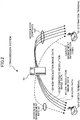
- FIG. 2 is a schematic view illustrating a state of reception and transmission of image data, sound data, and various management information items in the transmission system 1.
- FIG. 3 is a schematic view illustrating picture quality of image data.
- the transmission system 1 illustrated in FIG. 1 is constituted with multiple call terminals (10aa, 10ab, ...), displays (120aa, 120ab, ...) for the call terminals (10aa, 10ab, ...), multiple electronic blackboards (20a, 20b, 20c, 20d), a transmission management system 50, a program providing system 90, and a maintenance system 100.
- an arbitrary one of the multiple call terminals (10aa, 10ab, ...) will be referred to as a "call terminal 10"
- an arbitrary one of the multiple displays (120aa, 120ab, ...) will be referred to as an "display 120”.
- an arbitrary one of the multiple electronic blackboards (20a, 20b, 20c, 20d) will be referred to as an "electronic blackboard 20”.
- the call terminals 10 and the electronic blackboards 20 may be collectively referred to as "transmission terminals" in the embodiment.
- a call terminal 10 being a request source that requests start of communication for a video-conference or the like will be referred to as a "starter terminal”
- a call terminal 10 being a request destination (relay destination) will be referred to as a "destination terminal”.
- This "destination terminal” may be referred to as a "partner terminal”.
- the call terminal 10 can transmit and receive contents data that is of at least one type among image data, sound data, and text data.
- the electronic blackboard 20 can transmit and receive contents data that is of at least one type among image data and coordinates data, which will be described later.
- text data may be data that represents a message used in a chat or the like.
- a session for management information "sei" is established between the starter terminal 80 and the destination terminal 81, to transmit and receive various management information items via the transmission management system 50.
- four sessions are established between the starter terminal 80 and the destination terminal 81, to transmit and receive four types of data, namely, high-resolution image data 82, intermediate-resolution image data 83, low-resolution image data 84, and sound data (audio data) 85, by using H.264/SVC video encoding standards via the transmission control system 50.
- these four sessions are collectively illustrated as sessions for contents "sed”.
- the transmission control system 50 does not necessarily mediate between the starter terminal 80 and the destination terminal 81; the sessions for contents "sed” may be established directly between the starter terminal 80 and the destination terminal 81. Further, such a relationship between the starter terminal 80 and the destination terminal 81 may be applicable not only between a call terminal and a call terminal, but also between a call terminal and an electronic blackboard, between an electronic blackboard and a call terminal, and between an electronic blackboard and an electronic blackboard.
- image data is transmitted between the starter terminal 80 and the destination terminal 81, by using H.264/SVC video encoding standards.
- H.264/SVC is an example of video encoding standards, and other video encoding standards may be used. For example, H.264/AVC, H.265, VP9, and the like may be considered as the other standards.
- intermediate picture-quality image data is relayed, including low-resolution images being base images, and intermediate-resolution images. If the bandwidth of a route is very wide, high picture-quality image data is relayed, including low-resolution images being base images, intermediate-resolution images, and high-resolution images.
- each electronic blackboard 20 illustrated in FIG. 1 is a white board (a copy board) that is used in a company, a school, or the like, with which a user can make drawings by contacting a display 3 with an electronic pen 4 or a hand H, which will be described later, and contents of the drawings are electronically converted to generate stroke array data, which will be described later.
- a white board a copy board
- the transmission control system 50 illustrated in FIG. 1 relays contents data among multiple call terminals 10.
- the transmission control system 50 authenticates a login from a call terminal 10, manages call states of call terminals 10, manages an address list, and the like, in a unified way.
- images in image data may be moving pictures or still pictures, or may be both moving pictures and still pictures.
- routers select optimal paths for image data and audio data. Note that in the following, an arbitrary one of the routers (70a, 70b, 70c, 70d, 70ab, 70cd) will be referred to as a "router 70".
- the program providing system 90 includes an HD (Hard Disk) 204, which will be described later, to store a program for a call terminal to implement various functions on the call terminal 10 (or to have the call terminal 10 function as various functional units), and can transmit the program for a call terminal to the call terminal 10.
- the HD 204 of the program providing system 90 also stores a program for an electronic blackboard to implement various functions on the electronic blackboard 20 (or to have to the electronic blackboard 20 function as various functional units), and can transmit the program for an electronic blackboard to the electronic blackboard 20.
- the HD 204 of the program providing system 90 further stores a program for transmission control to implement various functions on the transmission management system 50 (or to have the transmission management system 50 function as various functional units), and can transmit the program for transmission control to the transmission management system 50.
- the maintenance system 100 is a computer for conservation, management, and maintenance of at least one of the call terminals 10, the transmission control system 50, and the program providing system 90. For example, if the maintenance system 100 is installed domestically, and the call terminals 10, the transmission control system 50, and the program providing system 90 are installed overseas, then, the maintenance system 100 remotely executes conservation, management, and maintenance of at least one of the call terminals 10, the transmission control system 50, and the program providing system 90, via a communication network 2. Also, the maintenance system 100 maintains or manages the product code, manufacturer's serial number, buyer, maintenance checkup, or failure history of at least one of the call terminals 10, the transmission control system 50, and the program providing system 90, without mediated by the communication network 2.
- the call terminals (10aa, 10ab, 10ac, ...), the electronic blackboard 20a, and the router 70a are connected to a LAN 2a to be capable of communicating with each other.
- the call terminals (10ba, 10bb, 10bc, ...), the electronic blackboard 20b, and the router 70b are connected to a LAN 2b to be capable of communicating with each other.
- the LAN 2a and the LAN 2b are connected to be capable of communicating with each other, by a dedicated line 2ab including the router 70ab, and set up in a predetermined region A.
- the region A is an office in Tokyo
- the LAN 2a is set up in a first business department
- the LAN 2b is set up in a second business department.
- the call terminals (10ca, 10cb, 10cc, ...), the electronic blackboard 20c, and the router 70c are connected to a LAN 2c to be capable of communicating with each other.
- the call terminals (10da, 10db, 10dc, ...), the electronic blackboard 20d, and the router 70d are connected to a LAN 2d to be capable of communicating with each other.
- the LAN 2c and the LAN 2d are connected to be capable of communicating with each other, by a dedicated line 2cd including the router 70cd, and set up in a predetermined region B.
- the region B is an office in Osaka
- the LAN 2c is set up in a first development department
- the LAN 2d is set up in a second development department.
- the region A and the region B are connected to the Internet 2i to be capable of communicating with each other via the respective routers (70ab, 70cd).
- the transmission control system 50, the program providing system 90, and the maintenance system 100 are connected with the call terminals 10 and the electronic blackboards 20 via the Internet 2i to be capable of communicating with each other.
- the transmission control system 50, the program providing system 90, and the maintenance system 100 may be set up in the region A or the region B, or may be set up in a region other than these.
- the LAN 2a, LAN 2b, dedicated line 2ab, Internet 2i, dedicated line 2cd, LAN 2c, and LAN 2d constitute the communication network 2 of the embodiment.
- This communication network 2 may include not only a part connected by wire, but also a part connected by wireless communication such as WiFi (Wireless Fidelity) and Bluetooth (trademark).
- sets of four numerals attached below the call terminals 10, the electronic blackboards 20, the transmission control system 50, the routers 70, the program providing system 90, and the maintenance system 100 represent respective IP addresses in the IPv4 format in a simplified manner.
- the IP address of the call terminal 10aa is 1. 2. 1. 3.
- IPv6 may be used instead of IPv4, IPv4 is used to simplify the description.
- the call terminals 10 and the electronic blackboards 20 may be used not only for communication between multiple offices, or communication between different rooms in the same office, but also for communication in the same room, or communication between the outdoors and indoors, or between the outdoors. If the call terminal 10 is used outdoors, communication may be executed wirelessly by a cellular phone communication network or the like.
- FIG. 4 is an external view of the call terminal 10. It is assumed in the following description that X-axis is the longitudinal direction of the call terminal 10, Y-axis is the direction perpendicular to the X-axis on the horizontal plane, and Z-axis is the direction perpendicular to the X-axis and Y-axis (the vertical direction).
- the call terminal 10 includes a chassis 1100, an arm 1200, and a camera housing 1300.
- a front side surface 1110 of the chassis 1100 has multiple air intake holes (not shown), and a rear side surface 1120 of the chassis 1100 has multiple air outlet holes 1121. With these holes, outside air can be taken in by driving a cooling fan built in the chassis 1100, through the air intake holes (not shown), then exhausted through the air outlet holes 1121.
- a right side surface 1130 of the chassis 1100 has a sound pickup hole 1131, through which voices, sounds, noises, and the like are captured by a built-in microphone 114, which will be described later.
- the chassis 1100 has an operation panel 1150 formed on the side closer to the right wall 1130.
- the operation panel 1150 has multiple operation buttons 108a-108e, a power switch 109, an alarm lamp 119, and a sound output hole 1151 through which sounds output from a built-in loudspeaker 115 reaches outside. These parts will be described later.
- a concave shaped housing part 1160 is provided to hold the arm 1200 and the camera housing 1300.
- the right side surface 1130 of the chassis 1100 also has multiple connectors 1132a-1132c to electrically connect cables to an external device connection interface 118, which will be described later.
- the left side surface 1140 of the chassis 1100 has a connector (not shown) to electrically connect a cable 120c for a display 120 to the external device connection interface 118.
- an "operation button 108” will be used when designating an arbitrary one of the operation buttons 108a-108b, and a “connector 1132” will be used when designating an arbitrary one of the connectors 1132a-1132c.
- the arm 1200 is attached to the chassis 1100 via a torque hinge 1210, and is configured to be capable of rotating vertically up to 135 degrees of tilt angle ⁇ 1 relative to the chassis 1100.
- the tilt angle ⁇ 1 is set to 90 degrees.
- the camera housing 1300 has a built-in camera 112 to take an image of a user, a document, or a room, which will be described later.
- the camera housing 1300 also has a torque hinge 1310.
- the camera housing 1300 is attached to the arm 1200 via the torque hinge 1310. Further, the camera housing 1300 is attached to the arm 1200 via the torque hinge 1310, and is configured to be capable of rotating vertically up to ⁇ 180 degrees of pan angle ⁇ 2, or horizontally up to ⁇ 45 degrees of tilt angle ⁇ 3, relative to zero degree corresponding to the angles with respect to the arm 1200 in FIG. 4 .
- FIG. 5 is an external view of the electronic blackboard 20.
- the electronic blackboard 20 is constituted with a leg portion 230 having multiple casters disposed on the lower side, a pillar 240 disposed on the upper side of the leg portion 230, and the display 3 that also serves as the main body of the electronic blackboard, disposed on the upper side of the pillar 240.
- the display 3 that also serves as the main body of the electronic blackboard has a CPU 201 built in, which will be described later.
- FIG. 4 and FIG. 5 are just examples; the call terminal 10 and the electronic blackboard 20 may have other appearances, respectively.
- the transmission control system 50, the program providing system 90, and the maintenance system 100 have the same appearance as a general server or a computer, and description of the appearance is omitted.
- FIG. 6 is a hardware configuration diagram of the call terminal 10.
- the terminal 10 in the embodiment includes a CPU (Central Processing Unit) 101 to control the overall operations of the call terminal 10; a ROM (Read Only Memory) 102 to store programs to drive the CPU 101 such as an IPL (Initial Program Loader); a RAM (Random Access Memory) 103 used as a work area for the CPU 101; a flash memory 104 to store a program for the call terminal and various data items such as image data and audio data; an SSD (Solid State Drive) 105 to control writes/reads of various data items on the flash memory 104 under control of the CPU 101; a media drive 107 to control writes/reads of the data on a recording medium 106 such as a flash memory; operational buttons 108 operated when selecting a destination of the call terminal 10 and the like; the power switch 109 to switch the power of the call terminal 10 on and off; and a network I/F (interface) 111 to transmit data using the communication network 2.
- a CPU Central Processing Unit
- the call terminal 10 also includes the built-in camera 112 to obtain image data by capturing an image of an object under control of the CPU 101; an imaging device I/F 113 to control driving the camera 112; the built-in microphone 114 to input sound; the built-in loudspeaker 115 to output sound; a sound input/output I/F 116 to input/output audio signals with the microphone 114 and the loudspeaker 115 under control of the CPU 101; a display I/F 117 to transfer image data to the external display 120 under control of the CPU 101; the external device connection I/F 118 to connect various external devices at connectors (not illustrated) in FIG. 4 ; the alarm lamp 119 to indicate faults of various functions in the call terminal 10; and a bus line 110 including an address bus, a data bus, and the like to electrically connect the above elements as illustrated in FIG. 6 .
- the display 120 is a unit for displaying image data of an object, operational icons, and the like, constituted with a liquid crystal display or an organic electroluminescence display.
- the display 120 is connected to the display I/F 117 by the cable 120c.
- the cable 120c may be a cable for analog RGB (VGA) signals, may be a cable for component video, or may be a cable for HDMI (trademark) (High-Definition Multimedia Interface) or DVI (Digital Video Interactive).
- the camera 112 includes a solid-state imaging device to convert light into electric charges to electronize an image of an object, in which a CMOS (Complementary Metal Oxide Semiconductor) or CCD (Charge Coupled Device) may be used as the solid-state imaging device.
- CMOS Complementary Metal Oxide Semiconductor
- CCD Charge Coupled Device
- the external device connection I/F 118 may be connected with an external camera, an external microphone, an external loudspeaker, or the like, with a USB (Universal Serial Bus) cable or the like. If an external camera is connected, the external camera is driven under control of the CPU 101, with priority over the built-in camera 112. Similarly, if an external microphone is connected, or if an external loudspeaker is connected, the external microphone or the external loudspeaker is driven under control of the CPU 101, with priority over the built-in microphone 114 or the built-in loudspeaker 115, respectively.
- USB Universal Serial Bus
- the camera 112, the microphone 114, and the loudspeaker 115 are not necessarily built in, but a configuration may be considered in which only an external camera, an external microphone, and an external loudspeaker can be connected.
- the display 120 may be built in the call terminal 10, or instead of the display 120, a projection device such as a projector may be used.
- the recording medium 106 is configured to be easily attached to or detached from the call terminal 10.
- an EEPROM Electrical Erasable and Programmable ROM
- EEPROM Electrical Erasable and Programmable ROM
- FIG. 7 is a hardware configuration diagram of the electronic blackboard 20.
- the electronic blackboard 20 includes a CPU 201 to control the overall operations of the electronic blackboard 20; a ROM 202 to store programs to be used for driving the CPU 201, such as an IPL; a RAM 203 used as a work area for the CPU 201; an SSD 204 to store various data items of a program for the electronic blackboard 20; a network controller 205 to control communication with the communication network 2; and an external memory controller 206 to control communication with a USB memory 5.
- a CPU 201 to control the overall operations of the electronic blackboard 20
- a ROM 202 to store programs to be used for driving the CPU 201, such as an IPL
- a RAM 203 used as a work area for the CPU 201
- an SSD 204 to store various data items of a program for the electronic blackboard 20
- a network controller 205 to control communication with the communication network 2
- an external memory controller 206 to control communication with a USB memory 5.
- the electronic blackboard 20 also includes a capturing device 211 to capture a still picture or a moving picture that is displayed on a display of a note PC 6; a GPU (Graphics Processing Unit) 112 dedicated to processing graphics; and a display controller 213 to control and manage a screen display to output an image output from the GPU 112.
- a capturing device 211 to capture a still picture or a moving picture that is displayed on a display of a note PC 6
- a GPU Graphics Processing Unit
- display controller 213 to control and manage a screen display to output an image output from the GPU 112.
- the electronic blackboard 20 includes a sensor controller 214 to control a process of a touch sensor 215; and the touch sensor 215 to detect a contact by the electronic pen 4 or the user's hand H on the display 3.
- This touch sensor 215 receives coordinates as input by an infrared cut-off method, and detects the coordinates.
- This method of inputting coordinates and detecting coordinates is a method in which two light reception/emission devices (not illustrated) disposed at both ends on the upper side of the display 3, emit multiple infrared rays parallel to the display 3, and receive the light that is reflected by a reflecting member disposed around the display 3, and comes back through the same light path as the light emitted by light reception elements has gone through.
- the touch sensor 215 outputs IDs (Identifications) of the infrared rays that have been emitted by the two light reception/emission devices, and cut off by an object, to the sensor controller 214, and the sensor controller 214 identifies a coordinate position which is a contact position of the object. Note that all IDs described in the following are examples of identification information.
- the touch sensor 215 is not limited to an infrared cut-off method, but various detection units may be used including a touch panel of an electrostatic capacitance type that identifies a contact position by detecting a change of the electrostatic capacitance; a touch panel of a resistance film method to identify a contact position by a voltage change of two resistor films facing each other; and a touch panel of an electromagnetic induction type to identify a contact position by detecting electromagnetic induction generated by a contact object contacting the display part.
- the electronic blackboard 20 also includes an electronic pen controller 216.
- This electronic pen controller 216 communicates with the electronic pen 4, to determine whether there is a touch by the pen point or a touch by the pen tail on the display 3. Note that the electronic pen controller 216 may determine whether there is a touch not only by the pen point or the pen tail, but also by a part of the electronic pen 4 gripped by the user, or another part of the electronic pen.
- the electronic blackboard 20 further includes a bus line 220 including an address bus, a data bus, and the like to electrically connect the CPU 201, the ROM 202, the RAM 203, the SSD 204, the network controller 205, the external memory controller 206, the capturing device 211, the GPU 212, the sensor controller 214, and the electronic pen controller 216 as illustrated in FIG. 2 .
- a bus line 220 including an address bus, a data bus, and the like to electrically connect the CPU 201, the ROM 202, the RAM 203, the SSD 204, the network controller 205, the external memory controller 206, the capturing device 211, the GPU 212, the sensor controller 214, and the electronic pen controller 216 as illustrated in FIG. 2 .
- FIG. 8 is a hardware configuration diagram of the transmission control system 50, the program providing system 90, and the maintenance system 100. Note that in the following, as a representative case, a hardware configuration of the transmission control system 50 will be described.
- the transmission control system 50 includes a CPU 501 to control the overall operations of the transmission control system 50; a ROM 502 that stores a program to be used for driving the CPU 501, such as an IPL; a RAM 503 used as a work area for the CPU 501; an HD 504 to store various data items of a program for transmission control; a HDD (Hard Disk Drive) 505 to write/read various data items on the HD 504 under control of the CPU 501; a media drive 507 to control writes/reads of data on a recording medium 506 such as a flash memory; a display 508 to display various information items such as cursors, menus, windows, characters, and images; a network I/F 509 to transmit data by using the communication network 2; a keyboard 511 providing multiple keys to enter characters, numerals, various commands, etc.; a mouse 512 for various selections and executions, selection of an object, and moving the cursor; a CD-ROM drive 514 to control writes/reads of various data items on
- FIG. 9 is a functional block diagram of the call terminal 10.
- the call terminal 10 has units (functions) including a transceiver unit 11, an operational input reception unit 12, a login request unit 13, an imaging unit 14, a sound input unit 15a, a sound output unit 15b, a display control unit 16, a creation unit 17, a determination unit 18, and an access unit 19, which are implemented by the hardware configuration illustrated in FIG. 6 and execution of a program.
- the call terminal 10 also includes a storage unit 1000 constituted with the flash memory 104 illustrated in FIG. 6 .
- This storage unit 1000 stores destination list frame data that represents a frame part (a part other than a selection area, which will be described later) of a destination list screen, which will be described later, illustrated in FIG. 24 .
- the storage unit 1000 also stores a terminal ID, a password, and the like to identify the call terminal 10 itself.
- image data and sound data received while making a call with a destination terminal are overwritten and stored upon each reception. Among these, an image is displayed on the display 120 by image data yet to be overwritten, and a sound is output from the loudspeaker 115 by sound data yet to be overwritten.
- the storage unit 1000 includes a visual information management DB (Database) 1001 constituted with a visual information management table.
- FIG. 10 is a diagram illustrating a visual information management table.
- operational state information that represents an operational state of each destination candidate, is associated with visual information represented in a destination list displayed on the display 120, to be managed.
- the visual information is represented by, for example, various icons having shapes illustrated in FIG. 10 .
- the visual information items that constitute the visual information management table may be transmitted from the transmission control system 50 when a starter terminal makes a request for login at Step S42, which will be described later, or may be stored in the storage unit 1000 before factory shipment of the starter terminal.
- the operational state takes one of four types of states, online (ready to communicate), online (communicating), online (suspended), and offline.
- the transceiver unit 11 transmits and receives various data items (or information items) with other terminals, devices, and systems, via the communication network 2.
- the operational input reception unit 12 receives various input items or various selections by the user. For example, if the user turns on the power switch 109 illustrated in FIG. 6 , the operational input reception unit 12 illustrated in FIG. 9 receives the power-on operation, and turns on the power source. Also, the operational input reception unit 12 receives input of text data from the user of the call terminal 10.
- the login request unit 13 Upon the reception of the above power-on operation, the login request unit 13 transmits a request for login to request authentication of a login and a request for starting communication from the transceiver unit 11 to the transmission control system 50 via the communication network 2.
- the imaging unit 14 captures an image of an object, and outputs the obtained image data.
- the sound input unit 15a inputs sound data relating to this sound signal.
- the sound output unit 15b output a sound signal relating to sound data to the loudspeaker, to have the sound output from the loudspeaker 115.
- the display control unit 16 controls image data or the like to be output and displayed on the external display 120, or not to be output and displayed.
- the creation unit 17 creates and updates a destination list screen illustrated in FIG. 24 , based on the destination list frame data read out of the storage unit 1000, and destination list content information, which will be described later.
- the determination unit 18 periodically determines whether the call terminal 10 operates normally.
- the access unit 19 executes a process for storing various data items in the storage unit 1000, or reading various data items stored in the storage unit 1000.
- each ID in the embodiment is identification information to uniquely identify a transmission terminal (the call terminal 10 or the electronic blackboard 20), which is represented by languages, characters, symbols, various marks, and the like. Also, the ID may be identification information that is represented by a combination of at least two of the languages, characters, symbols, and various marks.
- FIG. 11 is a functional block diagram of the electronic blackboard 20.
- the electronic blackboard 20 has units (functions) including a video obtainment unit 21, a coordinate detection unit 22, an automatic adjustment unit 23, a touch detection unit 24, an event classification unit 25, an operation processing unit 26, a gesture processing unit 27, a video superimposing unit 28, an image processing unit 30, and a communication control unit 60, which are implemented by the hardware configuration illustrated in FIG. 7 and execution of a program.
- the video obtainment unit 21 obtains an output video of a video output device such as the note PC 6 connected by a cable.
- the video obtainment unit 21 analyzes this image signal to derive the resolution of an image frame, which is a display image formed by the video output device with this image signal, and image information about the update frequency of this image frame, and outputs the derived information to the image obtainment unit 31, which will be described later.
- the coordinate detection unit 22 detects the coordinate position of an event generated by a user on the display 3 (a touch operation by the user's hand H on the display 3 or the like). Also, the coordinate detection unit 22 detects the area of a touched part.
- the automatic adjustment unit 23 is activated when the electronic blackboard 20 is activated, to adjust image processing parameters of a sensor camera of the touch sensor 215 of an optical sensor type so that the touch sensor 215 can output an appropriate value to the coordinate detection unit 22.
- the touch detection unit 24 detects an event generated by the user, such as a pressing (touching) operation on the display 3 by the pen point of the electronic pen 4 or the pen tail of the electronic pen 4.
- the event classification unit 25 classifies the coordinates position of an event detected by the coordinate detection unit 22, and a detection result detected by the touch detection unit 24, into one of events among a stroke drawing, a UI operation, and a gesture operation.
- a stroke drawing, the UI operation, and the gesture operation will be described using FIG. 12 .
- FIG. 12 is a configuration diagram of image layers.
- the "stroke drawing” is an event generated when a stroke image (B), which will be described later, illustrated in FIG. 12 , is displayed on the display 3 by the user who presses the electronic pen 4 on the display 3, moves the electronic pen 4 while keeping the pressing state, and eventually detaches the electronic pen 4 from the display 3.
- a stroke drawing for example, a letter of the alphabet such as "S” or "T” is drawn on the display 3.
- this "stroke drawing” includes not only drawing an image, but also an event of deleting an image that has been drawn already, and editing an image that has been drawn.
- the "UI operation” is an event generated when a UI image (A), which will be described later, illustrated in FIG. 12 , is displayed on the display 3 by the user who presses a predetermined position by the electronic pen 4 or the hand H.
- a UI image A
- the color and the width of a line drawn by the electronic pen 4 are set.
- the "gesture operation” is an event generated when a stroke image (B), which will be described later, illustrated in FIG. 12 , is displayed on the display 3 by the user who touches the display 3 by the hand H, or moves the hand H on the display 3.
- a stroke image B
- the user can enlarge (or reduce) an image, change a display area, or switch a page, by moving the hand H in a state where the hand H is kept touching on the display 3.
- the operation processing unit 26 executes various operations following elements of the UI generated with the event.
- the elements of a UI may include, for example, a button, a list, a check box, and a text box.
- the gesture processing unit 27 executes an operation that corresponds to a gesture operation determined by the event classification unit 25.
- the video superimposing unit 28 displays a video having an image superimposed by the display superimposing unit 36, which will be described later, on a video output device (the display 3 or the like). Also, the video superimposing unit 28 displays a video transmitted from a video output device (the camera 7 or the like), on a video from another video output device (the note PC 6 or the like) by picture-in-picture. Further, the video superimposing unit 28 executes switching for a video displayed on a part of the display 3 by picture-in-picture, to be displayed on the entire screen of the display 3.
- the image processing unit 30 executes a process for superimposing image layers illustrated in FIG. 12 .
- the image processing unit 30 includes an image obtainment unit 31, a stroke processing unit 32, a UI image generation unit 33, a background generation unit 34, a layout management unit 35, a display superimposing unit 36, a page processing unit 37, a file processing unit 40, and a page data storage unit 300.
- the image obtainment unit 31 obtains, as images, frames in a video obtained by the video obtainment unit 21. Such an image corresponds to an output image (C) illustrated in FIG. 12 .
- the stroke processing unit 32 draws an image, deletes a drawn image, or edits a drawn image, based on an event relating to a stroke drawing classified by the event classification unit 25.
- Such an image by a stroke drawing corresponds to a stroke image (B) illustrated in FIG. 12 .
- the UI image generation unit 33 generates a UI (user interface) image set in the electronic blackboard 20 in advance. Such a UI image corresponds to a UI image (A) illustrated in FIG. 12 .
- the background generation unit 34 generates a background image to be displayed on the display 3. Such a background image corresponds to a background image (D) illustrated in FIG. 12 .
- the pattern of a background image may be solid color, grid display, or the like.
- the layout management unit 35 manages layout information that represents a layout of images output from the image obtainment unit 31, the stroke processing unit 32, the UI image generation unit 33, and the background generation unit 34, respectively, for the display superimposing unit 36. This makes it possible for the layout management unit 35 to issue a command to the display superimposing unit 36 about whether to display an output image (C) and a stroke image (B) or not to display, and if to display, positions in an UI image (A) and a background image (D).
- the display superimposing unit 36 superimposes the output image (C) from the image obtainment unit 31, the stroke image (B) from the stroke processing unit 32, the UI image (A) from the UI image generation unit 33, and the background image (D) from the background generation unit 34, following the layout specified by the layout management unit 35.
- the layers are in the sequence of the UI image (A), the stroke image (B), the output image (C), and the background image (D), and the user can see the superimposed images by this sequence.
- the display superimposing unit 36 can switch the superimposing for the image (C) and the image (D) illustrated in FIG. 12 , respectively, so that one of the images (C) and (D) is exclusively superimposed on the image (A) and the image (B). For example, in a state where the image (A), the image (B), and the image (C) are displayed at first, if a cable between the electronic blackboard 20 and a video output device (the note PC 6 or the like) is pulled out, the layout management unit 35 may specify the image (C) as not to be superimposed, and to display the image (D). In this case, the display superimposing unit 36 may execute processes for enlarging the display, reducing the display, and moving the display area.
- the page processing unit 37 aggregates data of the stroke image (B) and data of the output image (C) into single page data, and stores the single page data in the page data storage unit 300. Also, the page processing unit 37 transmits the page data stored in the page data storage unit 300 to the display superimposing unit 36 via the image obtainment unit 31 so that the video superimposing unit 28 can redisplay the page data on the display 3.
- the page processing unit 37 transmits the page data stored in the page data storage unit 300 to the communication control unit 60 via the image obtainment unit 31 so that the communication control unit 60 can transmit the page data (stroke array data and media data) to another electronic blackboard 20 or a call terminal 10. Also, the page processing unit 37 transmits the page data to the stroke processing unit 32, to transition to a state in which the stroke can be re-edited. Further, the page processing unit 37 can delete or copy the page data.
- the page processing unit 37 separates the single page data into stroke array data that represents the stroke image (B), and media data that represents the background image (D).
- data of the output image (C) displayed on the display 3 at the moment when the page processing unit 37 stores the data in the page data storage unit 300 is first stored in the page data storage unit 300, and then, read out as media data that represents the background image (D) when read out from the page data storage unit 300.
- the page processing unit 37 outputs the stroke array data that represents the stroke image (B) to the stroke processing unit 32.
- the page processing unit 37 outputs the media data that represents the background image (D) to the image obtainment unit 31.
- the page data storage unit 300 stores page data as illustrated in FIG. 13.
- FIG. 13 is a schematic view illustrating the page data.
- the page data is data of one page to be displayed on the display 3 (stroke data and image data). Note that since the page data includes a lot of parameter types, here, contents of the page data are separated into FIG. 13 to FIG. 16 for the description.
- the file processing unit 40 detects the abnormal end, and recovers unsaved page data. For example, in case of a normal end, the file processing unit 40 obtains the page data from the page data storage unit 300, and records the page data as a PDF file in a USB 5. However, in case of an abnormal end due to the power down or the like, the page data may remain as recorded in the page data storage unit 300. Therefore, when the power is turned on again, the file processing unit 40 reads the page data from the page data storage unit 300 to recover the data. Also, the file processing unit 40 reads the PDF file from the USB memory 5, and stores each page as page data in the page data storage unit 300.
- the page data includes the page data ID to identify a page; the start time that represents a time when displaying the page has been started; the finish time that represents a time when rewriting the content of the page by a stroke, a gesture, and the like has been finished; the stroke array data ID to identify stroke array data generated by strokes with the electronic pen 4 and the user's hand H; and the media data ID to identify media data, which are associated with each other.
- the stroke array data is data for displaying the stroke image (B) illustrated in FIG. 12 on the display 3.
- the media data is data for displaying the background image (D) illustrated in FIG. 12 on the display 3.
- the drawing is a one-stroke drawing, and hence, the single letter "S” of the alphabet is represented by a single stroke data ID.
- the drawing is a two-stroke drawing, and hence, the single letter "T” of the alphabet is represented by two stroke data IDs.
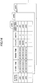
- the stroke array data also includes detailed information as illustrated in FIG. 14.
- FIG. 14 is a schematic view illustrating the stroke array data. As illustrated in FIG. 14 , a chunk of stroke array data is represented by multiple records of stroke data.
- a record of stroke data includes the stroke data ID to identify the record of stroke data; the start time that represents a time when a corresponding stroke has been started to be written; the finish time that represents a time when the stroke writing has been completed; the stroke color; the stroke width; and the coordinate array data ID to identify an array of passing points of the stroke.
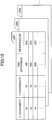
- this coordinate array data ID includes detailed information as illustrated in FIG. 15.
- FIG. 15 is a schematic view illustrating the coordinate array data.
- the coordinate array data includes information about, for each point of a stroke, (X coordinate value, Y coordinate value) of the point on the display 3, the time difference (ms) from the start time of the stroke when passing on this point, and the pen pressure of the electronic pen 4 at this point.
- a collection of points illustrated in FIG. 15 is represented by a record of coordinate array data illustrated in FIG. 14 .
- the drawing is one-stroke drawing that passes through multiple passing points, and the information about these multiple passing points is represented by the coordinate array data.
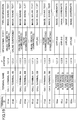
- FIG. 16 is a schematic view illustrating the media data.
- the media data includes the media data ID in the page data illustrated in FIG. 13 ; the data type of the media data; the record of time when the page processing unit 37 has recorded the page data in the page data storage unit 300; the position (X coordinate value, Y coordinate value) and the size (width, height) of an image to be displayed on the display 3; and the data representing content of the media data, which are associated with each other.
- the communication control unit 60 controls the electronic blackboard 20 executing a process for communicating with an external device such as the call terminal 10, the other electronic blackboards 20, the transmission control system 50, the program providing system 90, and the maintenance system 100.
- the communication control unit 60 includes a transceiver unit 61, a login request unit 63, an output superimposing unit 65, a creation unit 67, a determination unit 68, and an access unit 69.
- the communication control unit 60 further includes a storage unit 6000 constituted with the SSD 204 illustrated in FIG. 7 .
- the storage unit 6000 includes a visual information management DB (Database) 6001 constituted with a visual information management table.
- the communication control unit 60 includes a part of the functional configuration of the call terminal 10 illustrated in FIG. 9 .
- the transceiver unit 61, the login request unit 63, the creation unit 67, the determination unit 68, and the access unit 69 of the communication control unit 60 execute substantially the same processes as the transceiver unit 11, the login request unit 13, the creation unit 17, the determination unit 18, and the access unit 19 of the call terminal 10, respectively.
- the storage unit 6000 of the communication control unit 60 plays substantially the same role as the storage unit 1000 of the call terminal 10. Therefore, the description of these units is omitted.
- the output superimposing unit 65 superimposes image data with image data.
- the determination unit 68 periodically determines whether the electronic blackboard 20 operates normally.
- the transmission control system 50 has units (functions) including a transceiver unit 51, an authentication unit 52, a creation unit 53, a determination unit 58, and an access unit 59, which are implemented by the hardware configuration illustrated in FIG. 8 and execution of the program for transmission control.
- the transmission control system 50 includes a storage unit 5000 constituted with the HD 504 illustrated in FIG. 8 .
- This storage unit 5000 stores destination list frame data in a destination list screen illustrated in FIG. 24 (not including the destination list content information such as icons, "01aa", and "call terminal AA" illustrated in FIG. 24 ).
- the stroke array data will be referred to as "coordinates data”
- the media data will be referred to as “image data”.
- the type information managed in the terminal management DB 5002 includes "image” representing that image data can be processed, and "coordinates” representing that coordinates data can be processed.
- the storage unit 5000 includes an authentication management DB 5001 constituted with an authentication management table as illustrated in FIG. 18 .
- this authentication management table relevant information is managed in that for the terminal ID of every transmission terminal managed in the transmission control system 50 (the call terminals 10 and the electronic blackboards 20), a corresponding password is associated.
- the terminal 10aa has a terminal ID "01aa” associated with a password "aaaa”.
- the storage unit 5000 also includes a terminal management DB 5002 constituted with a terminal management table illustrated in FIG. 19 .
- this terminal management table relevant information is managed in that for the terminal ID of each transmission terminal (the call terminals 10 and the electronic blackboards 20), the terminal name of the transmission terminal, the IP address of the transmission terminal, operational state information that represents a current operational state of the transmission terminal, and type information that represents the type of data that can be processed by the transmission terminal are associated with the terminal ID.
- data that can be processed image data, sound data, text data, and coordinates data may be considered.
- reproduction of data may be considered.
- reproduction of image data an image is displayed on the displays 3 and 120.
- reproduction of sound data sound is output from the loudspeaker 115.
- By reproduction of text data content of text is displayed on the display 3.
- coordinates data a stroke image is displayed on the display 3.
- the call terminal 10aa having the terminal ID "01aa” has the terminal name "call terminal AA”; the IP address of this call terminal 10aa is "1.2.1.3”; this call terminal 10aa is in the operational state “online (ready to communicate)", and is capable of processing types of data "image”, “sound”, and "text”.
- each terminal ID is associated with type information that represents types of data processible by the corresponding transmission terminal, but the association is not limited as such; each of the type information items may be associated with the terminal IDs.
- the type information "image” is associated with terminal IDs "01aa”, “01ab”, and so on
- the type information "coordinates” is associated with terminal IDs "02aa”, "02ba”, and so on.
- a table different from the terminal management table illustrated in FIG. 19 may be provided to manage the terminal IDs having the type information associated.
- the storage unit 5000 further includes a destination list management DB 5003 constituted with a destination list management table illustrated in FIG. 20 .
- this destination list management table relevant information is managed in that for the terminal ID of each starter terminal that requests to start communication in a video-conference or the like is associated with terminal IDs of destination candidates that are registered as candidates of destination terminals.
- a record represents that destination candidates to which a starter terminal (a terminal 10aa) having the terminal ID "01aa can request to start communication with the call terminal 10ab having the terminal ID "01ab” the electronic blackboard 20a having the terminal ID "02aa”, and the others.
- the terminal IDs of the destination candidates are updated by addition or deletion in response to a request for the addition or deletion to the transmission control system 50, coming from any starter terminal.
- the storage unit 5000 further includes a session management DB 5004 constituted with a session management table illustrated in FIG. 21 .
- this session management table relevant information is managed in that each session ID to identify a session used for communication among multiple transmission terminals (the call terminals 10 and the electronic blackboards 20) is associated with terminal IDs of transmission terminals that are using the session identified by this session ID.
- a record represents that transmission terminals using a session executed by using a session ID "se1" are the call terminal 10ab having the terminal ID "01ab” and the electronic blackboard 20c having the terminal ID "02ca".
- the transceiver unit 51 transmits and receives various data items (or information items) with other terminals, devices, or systems via the communication network 2.
- the authentication unit 52 authenticates a terminal, by searching in the authentication management DB 5001 in the storage unit 5000, with a terminal ID and a password of the terminal included in a request for login received via the transceiver unit 51 as a search key, and determining whether the same pair of the terminal ID and the password are managed in the authentication management DB 5001.
- the creation unit 53 creates a session ID to be used for communication.
- the determination unit 58 determines whether type information transmitted from a transmission terminal via the transceiver unit 51 is included in type information read out from the terminal management DB 5002 by the access unit 59.
- the access unit 59 executes a process for storing various data items in the storage unit 5000, or reading various data items stored in the storage unit 5000.
- FIG. 22 is a diagram illustrating an overview of the operations or processes in the embodiment.
- FIG. 22 illustrates a case where a starter terminal 80 starts communication with a destination terminal 81, then, a transmission terminal newly participates in the communication (referred to as the "participating terminal"), and the communication is executed among the three transmission terminals.
- the starter terminal 80 is the electronic blackboard 20a
- the destination terminal 81 is the electronic blackboard 20b
- the participating terminal is the call terminal 10aa.
- the transmission control system 50 determines a transmission terminal that can process (reproduce or the like) the contents data among the destination terminal 81 and the participating terminal 86, based on the type information transmitted along with the contents data from the starter terminal 80, to transmit the contents data to the transmission terminal capable of the processing, and not to transmit the data to the transmission terminal incapable of the processing.
- the destination terminal 81 can reproduce both image data and coordinates data, and hence, the transmission control system 50 transmits the image data and the coordinates data to the destination terminal 81.
- the participating terminal 86 can process image data, but cannot process coordinates data, and hence, the transmission control system 50 transmits the image data to the participating terminal 86, but does not transmit the coordinates data.
- FIG. 23 is a sequence chart illustrating a process in a preparation stage for starting transmission and reception of contents data between transmission terminals.
- FIG. 24 is a schematic view of a destination list screen on the starter terminal 80.
- FIG. 25 is a sequence chart illustrating a process that starts with selection of a destination candidate, to be ready to start transmission and reception of contents data.
- FIG. 23 and FIG. 25 illustrate processes for transmitting and receiving various management information items, all by the session for management information "sei" illustrated in FIG. 2 .
- a user of the electronic blackboard 20a turns on the power switch (not illustrated) on the electronic blackboard 20a, to turn the power source on (Step S41).
- the login request unit 63 of the electronic blackboard 20a transmits a request for login from the transceiver unit 61 to the transmission control system 50 via the communication network 2 (Step S42).
- This request for login includes a terminal ID and a password to identify the starter terminal 80 as the electronic blackboard 20a.
- These terminal ID and password are data items that have been read out of the storage unit 6000 by the access unit 69, and have been transmitted to the transceiver unit 61.
- the transmission control system 50 on the reception side can obtain the IP address of the electronic blackboard 20a on the transmission side.
- the request for login is not necessarily started upon the power source having been turned on, but may be transmitted upon input by the user with the electronic pen 4 or the like.
- terminal ID and password have been read out of the storage unit 6000 to be transmitted, obtainment of the terminal ID and password is not limited as such; the terminal ID and password input by the user with the electronic pen 4 or the like may be transmitted. Also, the terminal ID and password read out of a recording medium connected to the electronic blackboard 20a, such as a SIM (Subscriber Identity Module Card) card and an SD card, may be transmitted.
- SIM Subscriber Identity Module Card
- the authentication unit 52 of the transmission control system 50 authenticates the terminal, by using the terminal ID and the password included in the request for login received via the transceiver unit 51 as a search key for searching in the authentication management table in the storage unit 5000 (see FIG. 18 ), and determining whether the same terminal ID and password are managed in the authentication management DB 5001 (Step S43).
- the authentication unit 52 has determined that the terminal has valid use permission.
- the access unit 59 reads out destination list frame data from the storage unit 5000 (Step S44).
- the transceiver unit 51 transmits information about authentication result representing an authentication result obtained by the authentication unit 52, to the starter terminal 80 (the electronic blackboard 20a) that has made the request for login, via the communication network 2 (Step S45). This makes the transceiver unit 61 of the starter terminal 80 (the electronic blackboard 20a) receive the information about authentication result.
- This information about authentication result includes the destination list frame data read out at Step S44.
- the starter terminal 80 (the electronic blackboard 20a) has the transceiver unit 61 make a request for content of the destination list to the transmission control system 50 via the communication network 2 (Step S46). This makes the transceiver unit 51 of the transmission control system 50 receive the request for the content of the destination list.
- This request includes the terminal ID of the starter terminal 80 (the electronic blackboard 20a).
- the access unit 59 of the transmission control system 50 searches in the destination list management table (see FIG. 20 ) by using the terminal ID "02aa" of the starter terminal 80 (the electronic blackboard 20a) received at Step S46 as a search key, to read out terminal IDs of all corresponding destination candidates (Step S47). Further, the access unit 59 searches in the terminal management table (see FIG. 19 ) by using each of the terminal IDs read out at Step S47 as a search key, to read the terminal name and operational state information of the corresponding destination candidate (Step S48).
- the transceiver unit 51 of the transmission control system 50 transmits the destination list content information to the starter terminal 80 (the electronic blackboard 20a) via the communication network 2 (Step S49). This makes the transceiver unit 11 of the starter terminal 80 (the electronic blackboard 20a) receive the destination list content information.
- This destination list content information includes the terminal ID of the destination candidate, and the terminal name and operational state information of the destination candidate read out at Steps S47 and S48, respectively.
- the creation unit 67 of the starter terminal 80 creates a destination list, by using the destination list frame data received at Step S45 and the destination list content information received at Step S49, and outputs the destination list to the image processing unit 30 (Step S50).
- the display superimposing unit 36 of the image processing unit 30 displays a destination list screen illustrated in FIG. 24 on the display 3 via the video superimposing unit 28 (Step S51).
- an icon representing an operational state of the destination candidate, the terminal ID of the destination candidate, and the destination name of the destination candidate are displayed.
- the icon representing an operational state is displayed on the destination list screen as the access unit 19 searches in the visual information management table (see FIG. 10 ) by the operational state information received at Step S49 as a search key, to read the corresponding visual information (the icon).
- the "terminal name" transmitted from the transmission control system 50 at Step S49 is displayed as the "destination name" on the destination list screen as illustrated in FIG. 24 .
- Steps S41 to S51 can be processed in substantially the same way not only on the electronic blackboards 20, but also on the call terminals 10.
- the coordinate detection unit 22 of the starter terminal 80 receives from the user selection of a destination candidate (here an electronic blackboard B) on the destination list screen illustrated in FIG. 24 (Step S101). Then, the transceiver unit 61 of the starter terminal 80 (the electronic blackboard 20a) transmits a request for start that represents a desire to start transmission and reception of contents data, to the transmission control system 50 (Step S102). This makes the transceiver unit 51 of the transmission control system 50 receive the request for start. Also, the request for start includes the terminal ID of the starter terminal 80 (the electronic blackboard 20a), and the terminal ID of the destination terminal 81 (the electronic blackboard 20b).
- the determination unit 58 determines whether the terminal ID of the destination terminal 81 received at Step S102 is managed in the session management table (see FIG. 21 ) (Step S103).
- the creation unit 53 newly creates a session ID (Step S104).
- the access unit 59 additionally stores a new record in the session management table (see FIG. 21 ), in which the session ID created at Step S104, and the terminal ID of the starter terminal 80 and the terminal ID of the destination terminal 81 received at Step S102 are associated with each other (Step S105).
- the session ID "se3" and the terminal IDs "02aa" and "02ba" are associated with each other to be managed.
- the transceiver unit 51 transmits a session start command that includes the session ID created at Step S104 to the starter terminal 80 (the electronic blackboard 20a) (Step S106). This makes the transceiver unit 61 of the starter terminal 80 (the electronic blackboard 20a) receive the session start command.
- the access unit 69 searches in the terminal management table (see FIG. 19 ) by the terminal ID of the destination terminal 81 (the electronic blackboard 20b) transmitted at Step S102 as a search key, to read the corresponding IP address (Step S107). Then, the transceiver unit 51 transmits a session start command that includes the session ID created at Step S104 to the IP address read out at Step S107 (Step S108). This makes the transceiver unit 61 of the destination terminal 81 (the electronic blackboard 20b) receive the session start command.
- the starter terminal 80 (the electronic blackboard 20a) and the destination terminal 81 (the electronic blackboard 20b) establish the communication session with the transmission control system 50, respectively (Steps S109-1 and 2).
- FIG. 26 is a schematic view of a destination list screen on the participating terminal 86.
- the operational input reception unit 12 of the participating terminal 86 receives selection of a destination candidate (here, a call terminal AA) on the destination list screen illustrated in FIG. 26 from a user of the participating terminal 86 (the call terminal 10 ca) (Step S121). Then, the transceiver unit 11 of the participating terminal 86 (the call terminal 10 ca) transmits a request for participation that represents a desire to start transmission and reception of contents data, to the transmission control system 50 (Step S122). This makes the transceiver unit 51 of the transmission control system 50 receive the request for participation.
- the request for participation includes the terminal ID of the participating terminal 86 (the call terminal 10aa), and the terminal ID of the starter terminal 80 (the electronic blackboard 20a). Note that instead of the terminal ID of the starter terminal 80 (the electronic blackboard 20a), the terminal ID of the destination terminal 81 (the electronic blackboard 20b) may be included.
- the transmission control system 50 has the determination unit 58 determines whether the terminal ID of the starter terminal 80 received at Step S122 is managed in the session management table (see FIG. 21 ) (Step S123).
- the terminal ID of the starter terminal 80 has come to be managed at Step S105, a new session ID is not created as has been done at Step S104.
- the transceiver unit 51 transmits a session start command that includes the session ID created at Step S104 to the participating terminal 86 (the call terminal 10aa) (Step S124). This makes the transceiver unit 11 of the participating terminal 86 (the call terminal 10aa) receive the session start command.
- the participating terminal 86 (the call terminal 10aa) establishes a communication session with the transmission control system 50 (Step S125).
- the electronic blackboard 20a comes to have two destination terminals 81 that are the electronic blackboard 20b and the call terminal 10aa. Note that among the destination candidates, transmission terminals that have come to actually execute communication become the destination terminals 81.
- FIG. 27 is a sequence chart illustrating transmission and reception of contents data.
- the transceiver unit 61 of the starter terminal 80 (the electronic blackboard 20a) transmits contents data, type information that represents the type of this contents data (an example of first type information), the terminal ID of the starter terminal 80 as the transmission source, and the session ID created at Step S104, to the transmission control system 50 (Step S201).
- image data is transmitted as the contents data
- "image" is transmitted as the type information.
- the transceiver unit 51 of the transmission control system 50 receive the image data, the type information "image", the terminal ID of the starter terminal 80, and the session ID.
- the transmission control system 50 determines the transmission destination of the received contents data (Step S202).
- Step S202 determines the transmission destination of the received contents data.
- FIG. 28 is a flowchart illustrating a process of determining the transmission destination.
- the access unit 59 searches in the session management table (see FIG. 21 ) by the session ID received at Step S201 as a search key, to read the terminals ID of the destination terminals 81 communicating with the terminal itself (the electronic blackboard 20aa) (Step S301).
- the access unit 59 searches in the terminal management table (see FIG. 19 ) by each of the terminals ID read at Step S301 as a search key, to read corresponding type information (an example of second type information) (Step S302).
- type information that represents "image” and "coordinates” is read as the type information associated with the terminal ID of "02ba" of a first destination terminal 81 (the electronic blackboard 20b).
- the determination unit 58 determines whether the type information received at Step S201 is included in the type information read out at Step S302, to determine whether to transmit the contents data received at Step S201 to the destination terminals 81 (Step S303). In other words, contents data of the type that can be processed for reproduction after received at a destination terminal 81 is transmitted to the destination terminal 81, but contents data of the type that cannot be processed for reproduction after received at the destination terminal 81 is not transmitted to the destination terminal 81.
- Step S303 if the determination unit 58 has determined that the type information received at Step S201 is included in the type information read out at Step S302 (YES at Step S303), the transceiver unit 51 transmits the contents data to the destination terminal 81 (Step S304). On the other hand, at Step S303, if the determination unit 58 has determined that the type information received at Step S201 is not included in the type information read out at Step S302 (NO at Step S303), the transceiver unit 51 does not execute Step S304 (does not transmit the contents data to the destination terminal 81).
- Step S305 determines whether the type information of processible contents data has been read for all destination terminals 81 (Step S305). If the determination unit 58 has determined that the type information of processible contents data has not been read for all destination terminals 81 (NO), the process goes back to Step S302 again. At Step S302 for this time, type information that represents "image”, "sound”, and "text” is read as type information that is associated with the terminal ID of "01aa" of a second destination terminal 81 (the call terminal 10aa). On the other hand, at Step S305, if the determination unit 58 has determined that the type information of processible contents data has been read for all destination terminals 81 (YES), the process ends for determining the transmission destination illustrated in FIG. 28 .
- the transceiver unit 51 of the transmission control system 50 transmits the contents data being image data, and the terminal ID of the starter terminal 80 (the electronic blackboard 20a) as the transmission source, to both the electronic blackboard 20b and the call terminal 10aa (Steps S203-1, 2).
- the transceiver unit 61 of the starter terminal 80 transmits the contents data being coordinates data to the transmission control system 50, and transmits "coordinates" as type information (Step S204), the transmission control system 50 determines the transmission destination similarly as at Step S202 (Step S205).
- the electronic blackboard 20b can reproduce the coordinates data as a stroke image (B)
- the call terminal 10aa cannot reproduce the coordinates data as a stroke image (B). Therefore, the transmission control system 50 transmits the contents data to the electronic blackboard 20b (Step S206), but does not transmit the contents data to the call terminal 10aa.
- the transmission control system 50 determines whether the second transmission terminal can process the contents data, based on the type information. Then, if the second transmission terminal can process the contents data, the transmission control system 50 transmits the contents data to the second transmission terminal; or if the second transmission terminal cannot process the contents data, the transmission control system 50 does not transmit the contents data to the second transmission terminal. Thus, effects are obtained that the transmission control system 50 does not need to execute useless transmission, and congestion of the communication network 2 can be avoided as much as possible.
- transmission control system 50 the program providing system 90, and the maintenance system 100 in the above embodiments may be constituted with a single computer, or may be divided into parts (functional units) to be constituted with multiple computers.
- a program transmitted by the program providing system 90 may be transmitted by partitioning the program into multiple modules, or may be transmitted without partitioning. Further, if the program providing system 90 is constituted with multiple computers, a program may be transmitted from the computers in a state where the program is partitioned into multiple modules.
- the transmission system 1 is applicable to any system as long as the system is a communication system in which transmission terminals can communicate with each other.
- the transmission system 1 is applicable to a TV (video) conference system, a sound conference system, a sound telephone system (including a cellular phone system), a text chat system, a white board share system, and the like.
- the transmission terminal may be a dedicated terminal for the communication system described above, a terminal specific to games, a personal computer, or a mobile communication terminal.
- Such mobile communication terminals include smart phones, cellular phone terminals, tablet-type terminals, wearable computer terminals, robots, and the like.
- wearable computer terminals include devices having communication functions (wrist watches, eyeglasses, dead-up displays, earphones, caps, gloves, shoes, and bags).
- the above programs may be recorded on computer-readable recording media such as CD-ROMs as files having a format installable or executable on a computer, to be distributed.
- the authentication management DB 5001, the terminal management DB 5002, the destination list management DB 5003, and the session management DB 5004 are constituted in the storage unit 5000 in the transmission control system 50, but the DBs are not limited to be constituted as such.
- at least one of the authentication management DB 5001, the terminal management DB 5002, the destination list management DB 5003, and the session management DB 5004 may be constituted in a storage unit of another server (a system) that is separate from the transmission control system 50.
- the access unit 59 of the transmission control system 50 accesses the other server (computer) via the transceiver unit 51, to store and read various information items.
- the terminal ID is used as an example of identification information, but the identification information is not limited as such; as another example of the identification information, a user ID to identify a user may be used.
- the authentication management DB 5001, the terminal management DB 5002, the destination list management DB 5003, and the session management DB 5004 are installed on the transmission control system 50, but the installation is not limited as such.
- at least one of the authentication management DB 5001, the terminal management DB 5002, the destination list management DB 5003, and the session management DB 5004 may be installed on a transmission management system (not illustrated) that can communicate with the transmission control system 50 via the communication network 2.
- the access unit 59 can access the various management DBs installed on the transmission management system via the communication network 2.
Landscapes
- Engineering & Computer Science (AREA)
- Multimedia (AREA)
- Signal Processing (AREA)
- Computer Networks & Wireless Communication (AREA)
- Two-Way Televisions, Distribution Of Moving Picture Or The Like (AREA)
- Telephonic Communication Services (AREA)
- Information Transfer Between Computers (AREA)
Abstract
Description
- The present disclosure relates to an invention about transmitting data received from a transmission terminal to another transmission terminal.
- Communication systems have become popular to communicate with remote locations via communication networks such as the Internet. As an example of such a communication system, a conference system for a remote conference may be considered (see Patent Document 1). In a common conference system, a call terminal used by a person concerned who is attending a remote conference on one side converts images of an object and sound in a conference room into digital data, and transmits the data to a call terminal used by a person concerned on the other side via a server (a computer). Next, the call terminal used by the person on the other side displays on a display the images from the one side, and outputs the sound from a loudspeaker. Thus, a conference between remote locations can be held in a state close to an actual conference.
- Also, electronic blackboards have been used for remote communication in companies, educational institutions, administrative agencies, and the like. Such an electronic blackboard can display a background image and a UI image (an operational image) on a display, and a user can draw a stroke image of characters, digits, figures, or the like on this background image (see Patent Document 2). This stroke image, which represents contents drawn by the user by contacting the display with an electronic pen or a hand, is drawn by the electronic blackboard that electronically converts the contents, and generates coordinates data.
- Further, the electronic blackboard can transmit and receive coordinates data and the like with another electronic blackboard or a call terminal described above via a server (a computer). If the electronic blackboard transmits coordinates data to another electronic blackboard via a server (a computer), the other electronic blackboard reproduces the stroke image from the coordinates data, and thus, a stroke image drawn on the electronic blackboard on the one side is displayed on the other electronic blackboard at a remote location. This makes the conference between the remote locations more convenient.
- However, a second transmission terminal such as a call terminal incapable of reproducing a stroke image cannot reproduce a stroke image from the coordinates data even if having received the coordinates data from a first transmission terminal such as an electronic blackboard via a server (a computer).
- As described above, if the server (the computer) or the like transmits data of a type that cannot be processed by the second transmission terminal, to the second transmission terminal, a problem arise in that the process of transmission is useless because the second transmission terminal cannot process the data.
- According to an embodiment, a transmission control system capable of transmitting data received from a first transmission terminal to a second transmission terminal, includes a receiver unit configured to receive identification information to identify the second transmission terminal or a user of the second transmission terminal, the data, and first type information that represents a type of the data, from the first transmission terminal; and a transmission control unit configured to control the received data not to be transmitted to the second transmission terminal in a case where the received first type information is not included in second type information corresponding to the received identification information, the second type information being managed in a management unit configured to have identification information to identify a predetermined transmission terminal or a user of the transmission terminal, associated with the second type information that represents a type of data processible by the predetermined transmission terminal.
- As described above, according to a transmission control system in the present disclosure, an effect is obtained in that unnecessary transmission can be avoided by controlling data not to be transmitted to the second transmission terminal, based on type information transmitted from the first transmission terminal.
-
-
FIG. 1 is an overview of a transmission system according to an embodiment; -
FIG. 2 is a schematic view illustrating a state of reception and transmission of image data, sound data, and various management information items in a transmission system; -
FIG. 3 is a schematic view illustrating picture quality of image data; -
FIG. 4 is an external view of a call terminal; -
FIG. 5 is an external view of an electronic blackboard; -
FIG. 6 is a hardware configuration diagram of a call terminal; -
FIG. 7 is a hardware configuration diagram of an electronic blackboard; -
FIG. 8 is a hardware configuration diagram of a transmission control system, a program providing system, and a maintenance system; -
FIG. 9 is a functional block diagram of a call terminal; -
FIG. 10 is a diagram illustrating a visual information management table; -
FIG. 11 is a functional block diagram of an electronic blackboard; -
FIG. 12 is a configuration diagram of image layers; -
FIG. 13 is a schematic view illustrating page data; -
FIG. 14 is a schematic view illustrating stroke data; -
FIG. 15 is a schematic view illustrating coordinates array data; -
FIG. 16 is a schematic view illustrating media data; -
FIG. 17 is a functional block diagram of atransmission control system 50; -
FIG. 18 is a schematic view of an authentication management DB; -
FIG. 19 is a schematic view of a terminal management DB; -
FIG. 20 is a schematic view of a destination list management DB; -
FIG. 21 is a schematic view of a session management table; -
FIG. 22 is a diagram illustrating an overview of operations or processes in an embodiment; -
FIG. 23 is a sequence chart illustrating a process in a preparation stage for starting transmission and reception of contents data between transmission terminals; -
FIG. 24 is a schematic view of a destination list screen on a starter terminal; -
FIG. 25 is a sequence chart illustrating a process that starts with selection of a destination candidate, to be ready to start transmission and reception of contents data; -
FIG. 26 is a schematic view of a destination list screen on a participating terminal; -
FIG. 27 is a sequence chart illustrating transmission and reception of contents data; and -
FIG. 28 is a flowchart illustrating a process of determining a transmission destination. - In the following, embodiments will be described with reference to the drawings. Note that the present invention is not limited to the embodiments below, but various modifications and replacements could be made without departing from the scope of the present invention.
- In the following, a transmission system will be described with reference to the drawings according to an embodiment.
- Note that the transmission system may include a communication system that mutually transfers information, emotions, and the like among multiple terminals. This communication system is a system for mutually transferring information, emotions, and the like among multiple terminals (a "call terminal" and an "electronic blackboard" in the embodiment are examples) via a communication control system (a "transmission control system" in the embodiment is an example), and a TV (video) conference system or the like may be considered as an example.
- First, an overall configuration of the embodiment will be described using
FIG. 1 to FIG. 3 .FIG. 1 is an overview of atransmission system 1 according to an embodiment.FIG. 2 is a schematic view illustrating a state of reception and transmission of image data, sound data, and various management information items in thetransmission system 1.FIG. 3 is a schematic view illustrating picture quality of image data. - First, the
transmission system 1 illustrated inFIG. 1 is constituted with multiple call terminals (10aa, 10ab, ...), displays (120aa, 120ab, ...) for the call terminals (10aa, 10ab, ...), multiple electronic blackboards (20a, 20b, 20c, 20d), atransmission management system 50, aprogram providing system 90, and amaintenance system 100. - In the following, an arbitrary one of the multiple call terminals (10aa, 10ab, ...) will be referred to as a "
call terminal 10", and an arbitrary one of the multiple displays (120aa, 120ab, ...) will be referred to as an "display 120". Also, an arbitrary one of the multiple electronic blackboards (20a, 20b, 20c, 20d) will be referred to as an "electronic blackboard 20". Further, thecall terminals 10 and theelectronic blackboards 20 may be collectively referred to as "transmission terminals" in the embodiment. Also, acall terminal 10 being a request source that requests start of communication for a video-conference or the like will be referred to as a "starter terminal", and acall terminal 10 being a request destination (relay destination) will be referred to as a "destination terminal". This "destination terminal" may be referred to as a "partner terminal". - Also, the
call terminal 10 can transmit and receive contents data that is of at least one type among image data, sound data, and text data. Also, theelectronic blackboard 20 can transmit and receive contents data that is of at least one type among image data and coordinates data, which will be described later. Note that text data may be data that represents a message used in a chat or the like. - Next, a method of communication will be described using
FIG. 2 in a case where both a starter terminal and a destination terminal are call terminals. In thetransmission system 1, a session for management information "sei" is established between thestarter terminal 80 and thedestination terminal 81, to transmit and receive various management information items via thetransmission management system 50. Also, four sessions are established between thestarter terminal 80 and thedestination terminal 81, to transmit and receive four types of data, namely, high-resolution image data 82, intermediate-resolution image data 83, low-resolution image data 84, and sound data (audio data) 85, by using H.264/SVC video encoding standards via thetransmission control system 50. Here, these four sessions are collectively illustrated as sessions for contents "sed". Note that although text data or coordinates data may also be transmitted and received in the sessions for contents "sed", the illustration is omitted here. Also, thetransmission control system 50 does not necessarily mediate between thestarter terminal 80 and thedestination terminal 81; the sessions for contents "sed" may be established directly between thestarter terminal 80 and thedestination terminal 81. Further, such a relationship between thestarter terminal 80 and thedestination terminal 81 may be applicable not only between a call terminal and a call terminal, but also between a call terminal and an electronic blackboard, between an electronic blackboard and a call terminal, and between an electronic blackboard and an electronic blackboard. In any of these cases, image data is transmitted between thestarter terminal 80 and thedestination terminal 81, by using H.264/SVC video encoding standards. Also, H.264/SVC is an example of video encoding standards, and other video encoding standards may be used. For example, H.264/AVC, H.265, VP9, and the like may be considered as the other standards. - Here, resolution of image data handled in the embodiment will be described. As illustrated in (c) in
FIG. 3 , there are a low-resolution image with 160-pixel wide and 120-pixel high as illustrated in (a) inFIG. 3 , which is a base image; an intermediate-resolution image with 320-pixel wide and 240-pixel high as illustrated in (b) inFIG. 3 ; and a high-resolution image with 640-pixel wide and 480-pixel high. Among these, if transferred through a narrow-bandwidth route, low-picture-quality image data is relayed, including only low-resolution images being base images. If the bandwidth of a route is relatively wide, intermediate picture-quality image data is relayed, including low-resolution images being base images, and intermediate-resolution images. If the bandwidth of a route is very wide, high picture-quality image data is relayed, including low-resolution images being base images, intermediate-resolution images, and high-resolution images. - Also, each
electronic blackboard 20 illustrated inFIG. 1 is a white board (a copy board) that is used in a company, a school, or the like, with which a user can make drawings by contacting adisplay 3 with anelectronic pen 4 or a hand H, which will be described later, and contents of the drawings are electronically converted to generate stroke array data, which will be described later. - Also, the
transmission control system 50 illustrated inFIG. 1 relays contents data amongmultiple call terminals 10. Thetransmission control system 50 authenticates a login from acall terminal 10, manages call states ofcall terminals 10, manages an address list, and the like, in a unified way. Note that images in image data may be moving pictures or still pictures, or may be both moving pictures and still pictures. - Multiple routers (70a, 70b, 70c, 70d, 70ab, 70cd) select optimal paths for image data and audio data. Note that in the following, an arbitrary one of the routers (70a, 70b, 70c, 70d, 70ab, 70cd) will be referred to as a "
router 70". - The
program providing system 90 includes an HD (Hard Disk) 204, which will be described later, to store a program for a call terminal to implement various functions on the call terminal 10 (or to have thecall terminal 10 function as various functional units), and can transmit the program for a call terminal to thecall terminal 10. TheHD 204 of theprogram providing system 90 also stores a program for an electronic blackboard to implement various functions on the electronic blackboard 20 (or to have to theelectronic blackboard 20 function as various functional units), and can transmit the program for an electronic blackboard to theelectronic blackboard 20. TheHD 204 of theprogram providing system 90 further stores a program for transmission control to implement various functions on the transmission management system 50 (or to have thetransmission management system 50 function as various functional units), and can transmit the program for transmission control to thetransmission management system 50. - The
maintenance system 100 is a computer for conservation, management, and maintenance of at least one of thecall terminals 10, thetransmission control system 50, and theprogram providing system 90. For example, if themaintenance system 100 is installed domestically, and thecall terminals 10, thetransmission control system 50, and theprogram providing system 90 are installed overseas, then, themaintenance system 100 remotely executes conservation, management, and maintenance of at least one of thecall terminals 10, thetransmission control system 50, and theprogram providing system 90, via acommunication network 2. Also, themaintenance system 100 maintains or manages the product code, manufacturer's serial number, buyer, maintenance checkup, or failure history of at least one of thecall terminals 10, thetransmission control system 50, and theprogram providing system 90, without mediated by thecommunication network 2. - Incidentally, the call terminals (10aa, 10ab, 10ac, ...), the
electronic blackboard 20a, and therouter 70a are connected to aLAN 2a to be capable of communicating with each other. The call terminals (10ba, 10bb, 10bc, ...), theelectronic blackboard 20b, and therouter 70b are connected to aLAN 2b to be capable of communicating with each other. Also, theLAN 2a and theLAN 2b are connected to be capable of communicating with each other, by a dedicated line 2ab including the router 70ab, and set up in a predetermined region A. For example, the region A is an office in Tokyo, theLAN 2a is set up in a first business department, and theLAN 2b is set up in a second business department. - On the other hand, the call terminals (10ca, 10cb, 10cc, ...), the
electronic blackboard 20c, and therouter 70c are connected to aLAN 2c to be capable of communicating with each other. The call terminals (10da, 10db, 10dc, ...), theelectronic blackboard 20d, and therouter 70d are connected to aLAN 2d to be capable of communicating with each other. Also, theLAN 2c and theLAN 2d are connected to be capable of communicating with each other, by a dedicated line 2cd including the router 70cd, and set up in a predetermined region B. For example, the region B is an office in Osaka, theLAN 2c is set up in a first development department, and theLAN 2d is set up in a second development department. The region A and the region B are connected to theInternet 2i to be capable of communicating with each other via the respective routers (70ab, 70cd). - Also, the
transmission control system 50, theprogram providing system 90, and themaintenance system 100 are connected with thecall terminals 10 and theelectronic blackboards 20 via theInternet 2i to be capable of communicating with each other. Thetransmission control system 50, theprogram providing system 90, and themaintenance system 100 may be set up in the region A or the region B, or may be set up in a region other than these. - Note that in the embodiment, the
LAN 2a,LAN 2b, dedicated line 2ab,Internet 2i, dedicated line 2cd,LAN 2c, andLAN 2d constitute thecommunication network 2 of the embodiment. Thiscommunication network 2 may include not only a part connected by wire, but also a part connected by wireless communication such as WiFi (Wireless Fidelity) and Bluetooth (trademark). - Also, in
FIG. 1 , sets of four numerals attached below thecall terminals 10, theelectronic blackboards 20, thetransmission control system 50, therouters 70, theprogram providing system 90, and themaintenance system 100 represent respective IP addresses in the IPv4 format in a simplified manner. For example, the IP address of the call terminal 10aa is 1. 2. 1. 3. Also, although IPv6 may be used instead of IPv4, IPv4 is used to simplify the description. - Note that the
call terminals 10 and theelectronic blackboards 20 may be used not only for communication between multiple offices, or communication between different rooms in the same office, but also for communication in the same room, or communication between the outdoors and indoors, or between the outdoors. If thecall terminal 10 is used outdoors, communication may be executed wirelessly by a cellular phone communication network or the like. - Next, a hardware configuration of the embodiment will be described using
FIG. 4 to FIG. 8 .FIG. 4 is an external view of thecall terminal 10. It is assumed in the following description that X-axis is the longitudinal direction of thecall terminal 10, Y-axis is the direction perpendicular to the X-axis on the horizontal plane, and Z-axis is the direction perpendicular to the X-axis and Y-axis (the vertical direction). - As illustrated in
FIG. 4 , thecall terminal 10 includes achassis 1100, anarm 1200, and acamera housing 1300.. Among these, afront side surface 1110 of thechassis 1100 has multiple air intake holes (not shown), and arear side surface 1120 of thechassis 1100 has multiple air outlet holes 1121. With these holes, outside air can be taken in by driving a cooling fan built in thechassis 1100, through the air intake holes (not shown), then exhausted through the air outlet holes 1121. Aright side surface 1130 of thechassis 1100 has asound pickup hole 1131, through which voices, sounds, noises, and the like are captured by a built-inmicrophone 114, which will be described later. - The
chassis 1100 has anoperation panel 1150 formed on the side closer to theright wall 1130. Theoperation panel 1150 hasmultiple operation buttons 108a-108e, apower switch 109, analarm lamp 119, and asound output hole 1151 through which sounds output from a built-inloudspeaker 115 reaches outside. These parts will be described later. On aleft side surface 1140 of thechassis 1100, a concave shapedhousing part 1160 is provided to hold thearm 1200 and thecamera housing 1300. Theright side surface 1130 of thechassis 1100 also hasmultiple connectors 1132a-1132c to electrically connect cables to an externaldevice connection interface 118, which will be described later. On the other hand, theleft side surface 1140 of thechassis 1100 has a connector (not shown) to electrically connect acable 120c for adisplay 120 to the externaldevice connection interface 118. - Note that in the following description, an "
operation button 108" will be used when designating an arbitrary one of theoperation buttons 108a-108b, and a "connector 1132" will be used when designating an arbitrary one of theconnectors 1132a-1132c. - The
arm 1200 is attached to thechassis 1100 via atorque hinge 1210, and is configured to be capable of rotating vertically up to 135 degrees of tilt angle θ1 relative to thechassis 1100. InFIG. 4 , the tilt angle θ1 is set to 90 degrees. - The
camera housing 1300 has a built-incamera 112 to take an image of a user, a document, or a room, which will be described later. Thecamera housing 1300 also has atorque hinge 1310. Thecamera housing 1300 is attached to thearm 1200 via thetorque hinge 1310. Further, thecamera housing 1300 is attached to thearm 1200 via thetorque hinge 1310, and is configured to be capable of rotating vertically up to ±180 degrees of pan angle θ2, or horizontally up to ±45 degrees of tilt angle θ3, relative to zero degree corresponding to the angles with respect to thearm 1200 inFIG. 4 . - Also,
FIG. 5 is an external view of theelectronic blackboard 20. As illustrated inFIG. 5 , theelectronic blackboard 20 is constituted with aleg portion 230 having multiple casters disposed on the lower side, apillar 240 disposed on the upper side of theleg portion 230, and thedisplay 3 that also serves as the main body of the electronic blackboard, disposed on the upper side of thepillar 240. Further, thedisplay 3 that also serves as the main body of the electronic blackboard has aCPU 201 built in, which will be described later. - Note that the external views illustrated in
FIG. 4 andFIG. 5 are just examples; thecall terminal 10 and theelectronic blackboard 20 may have other appearances, respectively. Thetransmission control system 50, theprogram providing system 90, and themaintenance system 100 have the same appearance as a general server or a computer, and description of the appearance is omitted. -
FIG. 6 is a hardware configuration diagram of thecall terminal 10. As illustrated inFIG. 6 , the terminal 10 in the embodiment includes a CPU (Central Processing Unit) 101 to control the overall operations of thecall terminal 10; a ROM (Read Only Memory) 102 to store programs to drive theCPU 101 such as an IPL (Initial Program Loader); a RAM (Random Access Memory) 103 used as a work area for theCPU 101; aflash memory 104 to store a program for the call terminal and various data items such as image data and audio data; an SSD (Solid State Drive) 105 to control writes/reads of various data items on theflash memory 104 under control of theCPU 101; amedia drive 107 to control writes/reads of the data on arecording medium 106 such as a flash memory;operational buttons 108 operated when selecting a destination of thecall terminal 10 and the like; thepower switch 109 to switch the power of thecall terminal 10 on and off; and a network I/F (interface) 111 to transmit data using thecommunication network 2. - The
call terminal 10 also includes the built-incamera 112 to obtain image data by capturing an image of an object under control of theCPU 101; an imaging device I/F 113 to control driving thecamera 112; the built-inmicrophone 114 to input sound; the built-inloudspeaker 115 to output sound; a sound input/output I/F 116 to input/output audio signals with themicrophone 114 and theloudspeaker 115 under control of theCPU 101; a display I/F 117 to transfer image data to theexternal display 120 under control of theCPU 101; the external device connection I/F 118 to connect various external devices at connectors (not illustrated) inFIG. 4 ; thealarm lamp 119 to indicate faults of various functions in thecall terminal 10; and abus line 110 including an address bus, a data bus, and the like to electrically connect the above elements as illustrated inFIG. 6 . - The
display 120 is a unit for displaying image data of an object, operational icons, and the like, constituted with a liquid crystal display or an organic electroluminescence display. Thedisplay 120 is connected to the display I/F 117 by thecable 120c. Thecable 120c may be a cable for analog RGB (VGA) signals, may be a cable for component video, or may be a cable for HDMI (trademark) (High-Definition Multimedia Interface) or DVI (Digital Video Interactive). Thecamera 112 includes a solid-state imaging device to convert light into electric charges to electronize an image of an object, in which a CMOS (Complementary Metal Oxide Semiconductor) or CCD (Charge Coupled Device) may be used as the solid-state imaging device. - The external device connection I/
F 118 may be connected with an external camera, an external microphone, an external loudspeaker, or the like, with a USB (Universal Serial Bus) cable or the like. If an external camera is connected, the external camera is driven under control of theCPU 101, with priority over the built-incamera 112. Similarly, if an external microphone is connected, or if an external loudspeaker is connected, the external microphone or the external loudspeaker is driven under control of theCPU 101, with priority over the built-inmicrophone 114 or the built-inloudspeaker 115, respectively. - Note that the
camera 112, themicrophone 114, and theloudspeaker 115 are not necessarily built in, but a configuration may be considered in which only an external camera, an external microphone, and an external loudspeaker can be connected. Also, thedisplay 120 may be built in thecall terminal 10, or instead of thedisplay 120, a projection device such as a projector may be used. Also, therecording medium 106 is configured to be easily attached to or detached from thecall terminal 10. Also, instead of theflash memory 104, an EEPROM (Electrically Erasable and Programmable ROM) or the like may be used, as long as the element is a memory on which reads/writes of data can be executed under control of theCPU 101. - Next, using
FIG. 7 , a hardware configuration of the electronic blackboard in the embodiment will be described. Note thatFIG. 7 is a hardware configuration diagram of theelectronic blackboard 20. - As illustrated in
FIG. 7 , theelectronic blackboard 20 includes aCPU 201 to control the overall operations of theelectronic blackboard 20; aROM 202 to store programs to be used for driving theCPU 201, such as an IPL; aRAM 203 used as a work area for theCPU 201; anSSD 204 to store various data items of a program for theelectronic blackboard 20; anetwork controller 205 to control communication with thecommunication network 2; and anexternal memory controller 206 to control communication with aUSB memory 5. - The
electronic blackboard 20 also includes acapturing device 211 to capture a still picture or a moving picture that is displayed on a display of anote PC 6; a GPU (Graphics Processing Unit) 112 dedicated to processing graphics; and adisplay controller 213 to control and manage a screen display to output an image output from theGPU 112. - Further, the
electronic blackboard 20 includes asensor controller 214 to control a process of atouch sensor 215; and thetouch sensor 215 to detect a contact by theelectronic pen 4 or the user's hand H on thedisplay 3. Thistouch sensor 215 receives coordinates as input by an infrared cut-off method, and detects the coordinates. This method of inputting coordinates and detecting coordinates is a method in which two light reception/emission devices (not illustrated) disposed at both ends on the upper side of thedisplay 3, emit multiple infrared rays parallel to thedisplay 3, and receive the light that is reflected by a reflecting member disposed around thedisplay 3, and comes back through the same light path as the light emitted by light reception elements has gone through. Thetouch sensor 215 outputs IDs (Identifications) of the infrared rays that have been emitted by the two light reception/emission devices, and cut off by an object, to thesensor controller 214, and thesensor controller 214 identifies a coordinate position which is a contact position of the object. Note that all IDs described in the following are examples of identification information. - The
touch sensor 215 is not limited to an infrared cut-off method, but various detection units may be used including a touch panel of an electrostatic capacitance type that identifies a contact position by detecting a change of the electrostatic capacitance; a touch panel of a resistance film method to identify a contact position by a voltage change of two resistor films facing each other; and a touch panel of an electromagnetic induction type to identify a contact position by detecting electromagnetic induction generated by a contact object contacting the display part. - The
electronic blackboard 20 also includes anelectronic pen controller 216. Thiselectronic pen controller 216 communicates with theelectronic pen 4, to determine whether there is a touch by the pen point or a touch by the pen tail on thedisplay 3. Note that theelectronic pen controller 216 may determine whether there is a touch not only by the pen point or the pen tail, but also by a part of theelectronic pen 4 gripped by the user, or another part of the electronic pen. - The
electronic blackboard 20 further includes abus line 220 including an address bus, a data bus, and the like to electrically connect theCPU 201, theROM 202, theRAM 203, theSSD 204, thenetwork controller 205, theexternal memory controller 206, thecapturing device 211, theGPU 212, thesensor controller 214, and theelectronic pen controller 216 as illustrated inFIG. 2 . - Next, a hardware configuration of the
transmission control system 50, theprogram providing system 90, and themaintenance system 100 will be described usingFIG. 8 according to the embodiment.FIG. 8 is a hardware configuration diagram of thetransmission control system 50, theprogram providing system 90, and themaintenance system 100. Note that in the following, as a representative case, a hardware configuration of thetransmission control system 50 will be described. - The transmission control system 50 includes a CPU 501 to control the overall operations of the transmission control system 50; a ROM 502 that stores a program to be used for driving the CPU 501, such as an IPL; a RAM 503 used as a work area for the CPU 501; an HD 504 to store various data items of a program for transmission control; a HDD (Hard Disk Drive) 505 to write/read various data items on the HD 504 under control of the CPU 501; a media drive 507 to control writes/reads of data on a recording medium 506 such as a flash memory; a display 508 to display various information items such as cursors, menus, windows, characters, and images; a network I/F 509 to transmit data by using the communication network 2; a keyboard 511 providing multiple keys to enter characters, numerals, various commands, etc.; a mouse 512 for various selections and executions, selection of an object, and moving the cursor; a CD-ROM drive 514 to control writes/reads of various data items on a CD-ROM (Compact Disc Read Only Memory) 513, which is an example of a recording medium attached/detached easily; and a bus line 510 including an address bus, a data bus, and the like to electrically connect the above elements.
- Next, functional configurations will be described especially for the
call terminal 10, theelectronic blackboard 20, and thetransmission control system 50 usingFIG. 9 to FIG. 21 . - First, a functional configuration of the
call terminal 10 will be described usingFIG. 9. FIG. 9 is a functional block diagram of thecall terminal 10. - The
call terminal 10 has units (functions) including atransceiver unit 11, an operationalinput reception unit 12, alogin request unit 13, animaging unit 14, asound input unit 15a, asound output unit 15b, adisplay control unit 16, acreation unit 17, adetermination unit 18, and anaccess unit 19, which are implemented by the hardware configuration illustrated inFIG. 6 and execution of a program. - Also, the
call terminal 10 also includes astorage unit 1000 constituted with theflash memory 104 illustrated inFIG. 6 . Thisstorage unit 1000 stores destination list frame data that represents a frame part (a part other than a selection area, which will be described later) of a destination list screen, which will be described later, illustrated inFIG. 24 . Thestorage unit 1000 also stores a terminal ID, a password, and the like to identify thecall terminal 10 itself. In thisstorage unit 1000, image data and sound data received while making a call with a destination terminal are overwritten and stored upon each reception. Among these, an image is displayed on thedisplay 120 by image data yet to be overwritten, and a sound is output from theloudspeaker 115 by sound data yet to be overwritten. Further, thestorage unit 1000 includes a visual information management DB (Database) 1001 constituted with a visual information management table. -
FIG. 10 is a diagram illustrating a visual information management table. In the visual information management table, operational state information that represents an operational state of each destination candidate, is associated with visual information represented in a destination list displayed on thedisplay 120, to be managed. Note that among destination candidates, a transmission terminal that has actually come to execute communication is the destination terminal described above. Also, the visual information is represented by, for example, various icons having shapes illustrated inFIG. 10 . The visual information items that constitute the visual information management table may be transmitted from thetransmission control system 50 when a starter terminal makes a request for login at Step S42, which will be described later, or may be stored in thestorage unit 1000 before factory shipment of the starter terminal. For example, the operational state takes one of four types of states, online (ready to communicate), online (communicating), online (suspended), and offline. - Referring back to
FIG. 9 , thetransceiver unit 11 transmits and receives various data items (or information items) with other terminals, devices, and systems, via thecommunication network 2. - The operational
input reception unit 12 receives various input items or various selections by the user. For example, if the user turns on thepower switch 109 illustrated inFIG. 6 , the operationalinput reception unit 12 illustrated inFIG. 9 receives the power-on operation, and turns on the power source. Also, the operationalinput reception unit 12 receives input of text data from the user of thecall terminal 10. - Upon the reception of the above power-on operation, the
login request unit 13 transmits a request for login to request authentication of a login and a request for starting communication from thetransceiver unit 11 to thetransmission control system 50 via thecommunication network 2. - The
imaging unit 14 captures an image of an object, and outputs the obtained image data. - After sound of the user has been converted to a sound signal by the
microphone 114, thesound input unit 15a inputs sound data relating to this sound signal. Thesound output unit 15b output a sound signal relating to sound data to the loudspeaker, to have the sound output from theloudspeaker 115. - The
display control unit 16 controls image data or the like to be output and displayed on theexternal display 120, or not to be output and displayed. - The
creation unit 17 creates and updates a destination list screen illustrated inFIG. 24 , based on the destination list frame data read out of thestorage unit 1000, and destination list content information, which will be described later. - The
determination unit 18 periodically determines whether thecall terminal 10 operates normally. - Also, the
access unit 19 executes a process for storing various data items in thestorage unit 1000, or reading various data items stored in thestorage unit 1000. - Note that each ID in the embodiment is identification information to uniquely identify a transmission terminal (the
call terminal 10 or the electronic blackboard 20), which is represented by languages, characters, symbols, various marks, and the like. Also, the ID may be identification information that is represented by a combination of at least two of the languages, characters, symbols, and various marks. - Next, a functional configuration of the
electronic blackboard 20 will be described usingFIG. 11 to FIG. 16 .FIG. 11 is a functional block diagram of theelectronic blackboard 20. - The
electronic blackboard 20 has units (functions) including avideo obtainment unit 21, a coordinatedetection unit 22, anautomatic adjustment unit 23, atouch detection unit 24, anevent classification unit 25, anoperation processing unit 26, agesture processing unit 27, avideo superimposing unit 28, animage processing unit 30, and acommunication control unit 60, which are implemented by the hardware configuration illustrated inFIG. 7 and execution of a program. - Among these, the
video obtainment unit 21 obtains an output video of a video output device such as thenote PC 6 connected by a cable. In response to receiving an image signal from the video output device, thevideo obtainment unit 21 analyzes this image signal to derive the resolution of an image frame, which is a display image formed by the video output device with this image signal, and image information about the update frequency of this image frame, and outputs the derived information to theimage obtainment unit 31, which will be described later. - The coordinate
detection unit 22 detects the coordinate position of an event generated by a user on the display 3 (a touch operation by the user's hand H on thedisplay 3 or the like). Also, the coordinatedetection unit 22 detects the area of a touched part. - The
automatic adjustment unit 23 is activated when theelectronic blackboard 20 is activated, to adjust image processing parameters of a sensor camera of thetouch sensor 215 of an optical sensor type so that thetouch sensor 215 can output an appropriate value to the coordinatedetection unit 22. - The
touch detection unit 24 detects an event generated by the user, such as a pressing (touching) operation on thedisplay 3 by the pen point of theelectronic pen 4 or the pen tail of theelectronic pen 4. - The
event classification unit 25 classifies the coordinates position of an event detected by the coordinatedetection unit 22, and a detection result detected by thetouch detection unit 24, into one of events among a stroke drawing, a UI operation, and a gesture operation. Here, the stroke drawing, the UI operation, and the gesture operation will be described usingFIG. 12 . Note thatFIG. 12 is a configuration diagram of image layers. - First, the "stroke drawing" is an event generated when a stroke image (B), which will be described later, illustrated in
FIG. 12 , is displayed on thedisplay 3 by the user who presses theelectronic pen 4 on thedisplay 3, moves theelectronic pen 4 while keeping the pressing state, and eventually detaches theelectronic pen 4 from thedisplay 3. By this stroke drawing, for example, a letter of the alphabet such as "S" or "T" is drawn on thedisplay 3. Note that this "stroke drawing" includes not only drawing an image, but also an event of deleting an image that has been drawn already, and editing an image that has been drawn. - The "UI operation" is an event generated when a UI image (A), which will be described later, illustrated in
FIG. 12 , is displayed on thedisplay 3 by the user who presses a predetermined position by theelectronic pen 4 or the hand H. By this UI operation, for example, the color and the width of a line drawn by theelectronic pen 4 are set. - The "gesture operation" is an event generated when a stroke image (B), which will be described later, illustrated in
FIG. 12 , is displayed on thedisplay 3 by the user who touches thedisplay 3 by the hand H, or moves the hand H on thedisplay 3. By this gesture operation, for example, the user can enlarge (or reduce) an image, change a display area, or switch a page, by moving the hand H in a state where the hand H is kept touching on thedisplay 3. - Next, referring back to
FIG. 11 , for a UI operation determined by theevent classification unit 25, theoperation processing unit 26 executes various operations following elements of the UI generated with the event. The elements of a UI may include, for example, a button, a list, a check box, and a text box. - The
gesture processing unit 27 executes an operation that corresponds to a gesture operation determined by theevent classification unit 25. - The
video superimposing unit 28 displays a video having an image superimposed by thedisplay superimposing unit 36, which will be described later, on a video output device (thedisplay 3 or the like). Also, thevideo superimposing unit 28 displays a video transmitted from a video output device (thecamera 7 or the like), on a video from another video output device (thenote PC 6 or the like) by picture-in-picture. Further, thevideo superimposing unit 28 executes switching for a video displayed on a part of thedisplay 3 by picture-in-picture, to be displayed on the entire screen of thedisplay 3. - (Functional configuration of image processing unit)
- Next, a functional configuration of the
image processing unit 30 will be described in detail. Theimage processing unit 30 executes a process for superimposing image layers illustrated inFIG. 12 . - Therefore, the
image processing unit 30 includes animage obtainment unit 31, astroke processing unit 32, a UI image generation unit 33, abackground generation unit 34, alayout management unit 35, adisplay superimposing unit 36, apage processing unit 37, afile processing unit 40, and a pagedata storage unit 300. - Among these, the
image obtainment unit 31 obtains, as images, frames in a video obtained by thevideo obtainment unit 21. Such an image corresponds to an output image (C) illustrated inFIG. 12 . - The
stroke processing unit 32 draws an image, deletes a drawn image, or edits a drawn image, based on an event relating to a stroke drawing classified by theevent classification unit 25. Such an image by a stroke drawing corresponds to a stroke image (B) illustrated inFIG. 12 . - The UI image generation unit 33 generates a UI (user interface) image set in the
electronic blackboard 20 in advance. Such a UI image corresponds to a UI image (A) illustrated inFIG. 12 . - The
background generation unit 34 generates a background image to be displayed on thedisplay 3. Such a background image corresponds to a background image (D) illustrated inFIG. 12 . The pattern of a background image may be solid color, grid display, or the like. - The
layout management unit 35 manages layout information that represents a layout of images output from theimage obtainment unit 31, thestroke processing unit 32, the UI image generation unit 33, and thebackground generation unit 34, respectively, for thedisplay superimposing unit 36. This makes it possible for thelayout management unit 35 to issue a command to thedisplay superimposing unit 36 about whether to display an output image (C) and a stroke image (B) or not to display, and if to display, positions in an UI image (A) and a background image (D). - The
display superimposing unit 36 superimposes the output image (C) from theimage obtainment unit 31, the stroke image (B) from thestroke processing unit 32, the UI image (A) from the UI image generation unit 33, and the background image (D) from thebackground generation unit 34, following the layout specified by thelayout management unit 35. Thus, as illustrated inFIG. 12 , the layers are in the sequence of the UI image (A), the stroke image (B), the output image (C), and the background image (D), and the user can see the superimposed images by this sequence. - Also, the
display superimposing unit 36 can switch the superimposing for the image (C) and the image (D) illustrated inFIG. 12 , respectively, so that one of the images (C) and (D) is exclusively superimposed on the image (A) and the image (B). For example, in a state where the image (A), the image (B), and the image (C) are displayed at first, if a cable between theelectronic blackboard 20 and a video output device (thenote PC 6 or the like) is pulled out, thelayout management unit 35 may specify the image (C) as not to be superimposed, and to display the image (D). In this case, thedisplay superimposing unit 36 may execute processes for enlarging the display, reducing the display, and moving the display area. - The
page processing unit 37 aggregates data of the stroke image (B) and data of the output image (C) into single page data, and stores the single page data in the pagedata storage unit 300. Also, thepage processing unit 37 transmits the page data stored in the pagedata storage unit 300 to thedisplay superimposing unit 36 via theimage obtainment unit 31 so that thevideo superimposing unit 28 can redisplay the page data on thedisplay 3. - Further, the
page processing unit 37 transmits the page data stored in the pagedata storage unit 300 to thecommunication control unit 60 via theimage obtainment unit 31 so that thecommunication control unit 60 can transmit the page data (stroke array data and media data) to anotherelectronic blackboard 20 or acall terminal 10. Also, thepage processing unit 37 transmits the page data to thestroke processing unit 32, to transition to a state in which the stroke can be re-edited. Further, thepage processing unit 37 can delete or copy the page data. - Also, when reading the page data from the page
data storage unit 300, thepage processing unit 37 separates the single page data into stroke array data that represents the stroke image (B), and media data that represents the background image (D). In other words, data of the output image (C) displayed on thedisplay 3 at the moment when thepage processing unit 37 stores the data in the pagedata storage unit 300, is first stored in the pagedata storage unit 300, and then, read out as media data that represents the background image (D) when read out from the pagedata storage unit 300. Then, among items of the page data read from the pagedata storage unit 300, thepage processing unit 37 outputs the stroke array data that represents the stroke image (B) to thestroke processing unit 32. Also, among the items of the page data read from the pagedata storage unit 300, thepage processing unit 37 outputs the media data that represents the background image (D) to theimage obtainment unit 31. - The page
data storage unit 300 stores page data as illustrated inFIG. 13. FIG. 13 is a schematic view illustrating the page data. The page data is data of one page to be displayed on the display 3 (stroke data and image data). Note that since the page data includes a lot of parameter types, here, contents of the page data are separated intoFIG. 13 to FIG. 16 for the description. - Referring back to
FIG. 11 , if theelectronic blackboard 20 has been terminated with an abnormal end, then, thefile processing unit 40 detects the abnormal end, and recovers unsaved page data. For example, in case of a normal end, thefile processing unit 40 obtains the page data from the pagedata storage unit 300, and records the page data as a PDF file in aUSB 5. However, in case of an abnormal end due to the power down or the like, the page data may remain as recorded in the pagedata storage unit 300. Therefore, when the power is turned on again, thefile processing unit 40 reads the page data from the pagedata storage unit 300 to recover the data. Also, thefile processing unit 40 reads the PDF file from theUSB memory 5, and stores each page as page data in the pagedata storage unit 300. - Here, the page data will be described in detail. As illustrated in
FIG. 13 , the page data includes the page data ID to identify a page; the start time that represents a time when displaying the page has been started; the finish time that represents a time when rewriting the content of the page by a stroke, a gesture, and the like has been finished; the stroke array data ID to identify stroke array data generated by strokes with theelectronic pen 4 and the user's hand H; and the media data ID to identify media data, which are associated with each other. The stroke array data is data for displaying the stroke image (B) illustrated inFIG. 12 on thedisplay 3. The media data is data for displaying the background image (D) illustrated inFIG. 12 on thedisplay 3. - By the page data as such, for example, if the user draws a letter "S" of the alphabet by the
electronic pen 4, the drawing is a one-stroke drawing, and hence, the single letter "S" of the alphabet is represented by a single stroke data ID. On the other hand, if the user draws a letter "T" of the alphabet by theelectronic pen 4, the drawing is a two-stroke drawing, and hence, the single letter "T" of the alphabet is represented by two stroke data IDs. - The stroke array data also includes detailed information as illustrated in
FIG. 14. FIG. 14 is a schematic view illustrating the stroke array data. As illustrated inFIG. 14 , a chunk of stroke array data is represented by multiple records of stroke data. A record of stroke data includes the stroke data ID to identify the record of stroke data; the start time that represents a time when a corresponding stroke has been started to be written; the finish time that represents a time when the stroke writing has been completed; the stroke color; the stroke width; and the coordinate array data ID to identify an array of passing points of the stroke. - Further, this coordinate array data ID includes detailed information as illustrated in
FIG. 15. FIG. 15 is a schematic view illustrating the coordinate array data. As illustrated inFIG. 15 , the coordinate array data includes information about, for each point of a stroke, (X coordinate value, Y coordinate value) of the point on thedisplay 3, the time difference (ms) from the start time of the stroke when passing on this point, and the pen pressure of theelectronic pen 4 at this point. In other words, a collection of points illustrated inFIG. 15 is represented by a record of coordinate array data illustrated inFIG. 14 . For example, if the user draws a letter "S" of the alphabet by theelectronic pen 4, the drawing is one-stroke drawing that passes through multiple passing points, and the information about these multiple passing points is represented by the coordinate array data. - Also, the media data among the items of the page data illustrated in
FIG. 13 includes detailed information as illustrated inFIG. 16. FIG. 16 is a schematic view illustrating the media data. As illustrated inFIG. 16 , the media data includes the media data ID in the page data illustrated inFIG. 13 ; the data type of the media data; the record of time when thepage processing unit 37 has recorded the page data in the pagedata storage unit 300; the position (X coordinate value, Y coordinate value) and the size (width, height) of an image to be displayed on thedisplay 3; and the data representing content of the media data, which are associated with each other. Among these, the position of an image to be displayed on thedisplay 3 by the page data represents the position of the upper left end of the image displayed by the page data, relative to the coordinates of the upper left end of thedisplay 3 represented by (X coordinate value, Y coordinate value)=(0, 0). - Referring back to
FIG. 11 , next, a functional configuration of thecommunication control unit 60 will be described in detail. Thecommunication control unit 60 controls theelectronic blackboard 20 executing a process for communicating with an external device such as thecall terminal 10, the otherelectronic blackboards 20, thetransmission control system 50, theprogram providing system 90, and themaintenance system 100. - Therefore, the
communication control unit 60 includes atransceiver unit 61, alogin request unit 63, anoutput superimposing unit 65, acreation unit 67, adetermination unit 68, and anaccess unit 69. Thecommunication control unit 60 further includes astorage unit 6000 constituted with theSSD 204 illustrated inFIG. 7 . Thestorage unit 6000 includes a visual information management DB (Database) 6001 constituted with a visual information management table. - Also, the
communication control unit 60 includes a part of the functional configuration of thecall terminal 10 illustrated inFIG. 9 . Specifically, thetransceiver unit 61, thelogin request unit 63, thecreation unit 67, thedetermination unit 68, and theaccess unit 69 of thecommunication control unit 60 execute substantially the same processes as thetransceiver unit 11, thelogin request unit 13, thecreation unit 17, thedetermination unit 18, and theaccess unit 19 of thecall terminal 10, respectively. Also, thestorage unit 6000 of thecommunication control unit 60 plays substantially the same role as thestorage unit 1000 of thecall terminal 10. Therefore, the description of these units is omitted. - The
output superimposing unit 65 superimposes image data with image data. - The
determination unit 68 periodically determines whether theelectronic blackboard 20 operates normally. - Next, using
FIG. 17 to FIG. 21 , a functional configuration of thetransmission control system 50 will be described. Thetransmission control system 50 has units (functions) including atransceiver unit 51, anauthentication unit 52, acreation unit 53, adetermination unit 58, and anaccess unit 59, which are implemented by the hardware configuration illustrated inFIG. 8 and execution of the program for transmission control. - Also, the
transmission control system 50 includes astorage unit 5000 constituted with theHD 504 illustrated inFIG. 8 . Thisstorage unit 5000 stores destination list frame data in a destination list screen illustrated inFIG. 24 (not including the destination list content information such as icons, "01aa", and "call terminal AA" illustrated inFIG. 24 ). - Note that to simplify the description in the following, the stroke array data will be referred to as "coordinates data", and the media data will be referred to as "image data". Further, the type information managed in the
terminal management DB 5002 includes "image" representing that image data can be processed, and "coordinates" representing that coordinates data can be processed. - The
storage unit 5000 includes anauthentication management DB 5001 constituted with an authentication management table as illustrated inFIG. 18 . In this authentication management table, relevant information is managed in that for the terminal ID of every transmission terminal managed in the transmission control system 50 (thecall terminals 10 and the electronic blackboards 20), a corresponding password is associated. For example, in the authentication management table illustrated inFIG. 18 , the terminal 10aa has a terminal ID "01aa" associated with a password "aaaa". - The
storage unit 5000 also includes aterminal management DB 5002 constituted with a terminal management table illustrated inFIG. 19 . In this terminal management table, relevant information is managed in that for the terminal ID of each transmission terminal (thecall terminals 10 and the electronic blackboards 20), the terminal name of the transmission terminal, the IP address of the transmission terminal, operational state information that represents a current operational state of the transmission terminal, and type information that represents the type of data that can be processed by the transmission terminal are associated with the terminal ID. As examples of data that can be processed, image data, sound data, text data, and coordinates data may be considered. Also, as an example of content of processing, reproduction of data may be considered. By reproduction of image data, an image is displayed on thedisplays loudspeaker 115. By reproduction of text data, content of text is displayed on thedisplay 3. By reproduction of coordinates data, a stroke image is displayed on thedisplay 3. - For example, in the terminal management table illustrated in
FIG. 19 , the call terminal 10aa having the terminal ID "01aa" has the terminal name "call terminal AA"; the IP address of this call terminal 10aa is "1.2.1.3"; this call terminal 10aa is in the operational state "online (ready to communicate)", and is capable of processing types of data "image", "sound", and "text". - Note that in the relevant information illustrated in
FIG. 19 , each terminal ID is associated with type information that represents types of data processible by the corresponding transmission terminal, but the association is not limited as such; each of the type information items may be associated with the terminal IDs. In this case, for example, the type information "image" is associated with terminal IDs "01aa", "01ab", and so on, and the type information "coordinates" is associated with terminal IDs "02aa", "02ba", and so on. However, in this case, a table different from the terminal management table illustrated inFIG. 19 may be provided to manage the terminal IDs having the type information associated. - The
storage unit 5000 further includes a destinationlist management DB 5003 constituted with a destination list management table illustrated inFIG. 20 . In this destination list management table, relevant information is managed in that for the terminal ID of each starter terminal that requests to start communication in a video-conference or the like is associated with terminal IDs of destination candidates that are registered as candidates of destination terminals. - For example, in the destination list management table illustrated in
FIG. 20 , a record represents that destination candidates to which a starter terminal (a terminal 10aa) having the terminal ID "01aa can request to start communication with the call terminal 10ab having the terminal ID "01ab" theelectronic blackboard 20a having the terminal ID "02aa", and the others. Note that the terminal IDs of the destination candidates are updated by addition or deletion in response to a request for the addition or deletion to thetransmission control system 50, coming from any starter terminal. - The
storage unit 5000 further includes asession management DB 5004 constituted with a session management table illustrated inFIG. 21 . In this session management table, relevant information is managed in that each session ID to identify a session used for communication among multiple transmission terminals (thecall terminals 10 and the electronic blackboards 20) is associated with terminal IDs of transmission terminals that are using the session identified by this session ID. For example, in the session management table illustrated inFIG. 21 , a record represents that transmission terminals using a session executed by using a session ID "se1" are the call terminal 10ab having the terminal ID "01ab" and theelectronic blackboard 20c having the terminal ID "02ca". - Next, a functional configuration of the
transmission control system 50 will be described usingFIG. 17 . - The
transceiver unit 51 transmits and receives various data items (or information items) with other terminals, devices, or systems via thecommunication network 2. - The
authentication unit 52 authenticates a terminal, by searching in theauthentication management DB 5001 in thestorage unit 5000, with a terminal ID and a password of the terminal included in a request for login received via thetransceiver unit 51 as a search key, and determining whether the same pair of the terminal ID and the password are managed in theauthentication management DB 5001. - The
creation unit 53 creates a session ID to be used for communication. Thedetermination unit 58 determines whether type information transmitted from a transmission terminal via thetransceiver unit 51 is included in type information read out from theterminal management DB 5002 by theaccess unit 59. - The
access unit 59 executes a process for storing various data items in thestorage unit 5000, or reading various data items stored in thestorage unit 5000. - Next, operations and processes of the embodiment will be described using
FIG. 22 to FIG. 28 . Note that first, an overview of the operations and processes of the embodiment will be described usingFIG. 22. FIG. 22 is a diagram illustrating an overview of the operations or processes in the embodiment. -
FIG. 22 illustrates a case where astarter terminal 80 starts communication with adestination terminal 81, then, a transmission terminal newly participates in the communication (referred to as the "participating terminal"), and the communication is executed among the three transmission terminals. Here, the case is illustrated in which thestarter terminal 80 is theelectronic blackboard 20a, thedestination terminal 81 is theelectronic blackboard 20b, and the participating terminal is the call terminal 10aa. - For example, if the
starter terminal 80 transmits contents data to thedestination terminal 81 and the participatingterminal 86 via thetransmission control system 50, thetransmission control system 50 determines a transmission terminal that can process (reproduce or the like) the contents data among thedestination terminal 81 and the participatingterminal 86, based on the type information transmitted along with the contents data from thestarter terminal 80, to transmit the contents data to the transmission terminal capable of the processing, and not to transmit the data to the transmission terminal incapable of the processing. Here, thedestination terminal 81 can reproduce both image data and coordinates data, and hence, thetransmission control system 50 transmits the image data and the coordinates data to thedestination terminal 81. On the other hand, the participatingterminal 86 can process image data, but cannot process coordinates data, and hence, thetransmission control system 50 transmits the image data to the participatingterminal 86, but does not transmit the coordinates data. - In the following, the operations or the processes of the embodiment will be described specifically, using
FIG. 23 to FIG. 28 .FIG. 23 is a sequence chart illustrating a process in a preparation stage for starting transmission and reception of contents data between transmission terminals.FIG. 24 is a schematic view of a destination list screen on thestarter terminal 80.FIG. 25 is a sequence chart illustrating a process that starts with selection of a destination candidate, to be ready to start transmission and reception of contents data. - Here, a process for transmitting and receiving management information items in a preparation stage before starting transmission and reception of contents data between the transmission terminal (the
electronic blackboard 20a) as thestarter terminal 80, and the transmission terminal (theelectronic blackboard 20b) as thedestination terminal 81 will be described. Note thatFIG. 23 andFIG. 25 illustrate processes for transmitting and receiving various management information items, all by the session for management information "sei" illustrated inFIG. 2 . - First, a user of the
electronic blackboard 20a turns on the power switch (not illustrated) on theelectronic blackboard 20a, to turn the power source on (Step S41). Then, upon the power source having been turned on, thelogin request unit 63 of theelectronic blackboard 20a transmits a request for login from thetransceiver unit 61 to thetransmission control system 50 via the communication network 2 (Step S42). This makes thetransceiver unit 51 of thetransmission control system 50 receive the request for login. This request for login includes a terminal ID and a password to identify thestarter terminal 80 as theelectronic blackboard 20a. These terminal ID and password are data items that have been read out of thestorage unit 6000 by theaccess unit 69, and have been transmitted to thetransceiver unit 61. - Note that when the request for login is transmitted from the
electronic blackboard 20a to thetransmission control system 50, thetransmission control system 50 on the reception side can obtain the IP address of theelectronic blackboard 20a on the transmission side. Also, the request for login is not necessarily started upon the power source having been turned on, but may be transmitted upon input by the user with theelectronic pen 4 or the like. - Further, although the terminal ID and password have been read out of the
storage unit 6000 to be transmitted, obtainment of the terminal ID and password is not limited as such; the terminal ID and password input by the user with theelectronic pen 4 or the like may be transmitted. Also, the terminal ID and password read out of a recording medium connected to theelectronic blackboard 20a, such as a SIM (Subscriber Identity Module Card) card and an SD card, may be transmitted. - Next, the
authentication unit 52 of thetransmission control system 50 authenticates the terminal, by using the terminal ID and the password included in the request for login received via thetransceiver unit 51 as a search key for searching in the authentication management table in the storage unit 5000 (seeFIG. 18 ), and determining whether the same terminal ID and password are managed in the authentication management DB 5001 (Step S43). In the embodiment, a case will be described where theauthentication unit 52 has determined that the terminal has valid use permission. - If the
authentication unit 52 has determined that the same terminal ID and the same password are managed, and hence, the request for login has come from thestarter terminal 80 having valid use permission, theaccess unit 59 reads out destination list frame data from the storage unit 5000 (Step S44). - The
transceiver unit 51 transmits information about authentication result representing an authentication result obtained by theauthentication unit 52, to the starter terminal 80 (theelectronic blackboard 20a) that has made the request for login, via the communication network 2 (Step S45). This makes thetransceiver unit 61 of the starter terminal 80 (theelectronic blackboard 20a) receive the information about authentication result. This information about authentication result includes the destination list frame data read out at Step S44. - Next, in response to receiving the information about authentication result indicating the authentication result of determination that the terminal has valid use permission, the starter terminal 80 (the
electronic blackboard 20a) has thetransceiver unit 61 make a request for content of the destination list to thetransmission control system 50 via the communication network 2 (Step S46). This makes thetransceiver unit 51 of thetransmission control system 50 receive the request for the content of the destination list. This request includes the terminal ID of the starter terminal 80 (theelectronic blackboard 20a). - Next, the
access unit 59 of thetransmission control system 50 searches in the destination list management table (seeFIG. 20 ) by using the terminal ID "02aa" of the starter terminal 80 (theelectronic blackboard 20a) received at Step S46 as a search key, to read out terminal IDs of all corresponding destination candidates (Step S47). Further, theaccess unit 59 searches in the terminal management table (seeFIG. 19 ) by using each of the terminal IDs read out at Step S47 as a search key, to read the terminal name and operational state information of the corresponding destination candidate (Step S48). - Next, the
transceiver unit 51 of thetransmission control system 50 transmits the destination list content information to the starter terminal 80 (theelectronic blackboard 20a) via the communication network 2 (Step S49). This makes thetransceiver unit 11 of the starter terminal 80 (theelectronic blackboard 20a) receive the destination list content information. This destination list content information includes the terminal ID of the destination candidate, and the terminal name and operational state information of the destination candidate read out at Steps S47 and S48, respectively. - Next, the
creation unit 67 of the starter terminal 80 (theelectronic blackboard 20a) creates a destination list, by using the destination list frame data received at Step S45 and the destination list content information received at Step S49, and outputs the destination list to the image processing unit 30 (Step S50). Then, thedisplay superimposing unit 36 of theimage processing unit 30 displays a destination list screen illustrated inFIG. 24 on thedisplay 3 via the video superimposing unit 28 (Step S51). - On this destination list screen, for each of the destination candidates, an icon representing an operational state of the destination candidate, the terminal ID of the destination candidate, and the destination name of the destination candidate are displayed. Among these, the icon representing an operational state is displayed on the destination list screen as the
access unit 19 searches in the visual information management table (seeFIG. 10 ) by the operational state information received at Step S49 as a search key, to read the corresponding visual information (the icon). Note that the "terminal name" transmitted from thetransmission control system 50 at Step S49 is displayed as the "destination name" on the destination list screen as illustrated inFIG. 24 . - Note that Steps S41 to S51 can be processed in substantially the same way not only on the
electronic blackboards 20, but also on thecall terminals 10. - Next, using
FIG. 25 , a process will be described that is executed after communication has been started between the transmission terminal (theelectronic blackboard 20a) as thestarter terminal 80 and the transmission terminal (theelectronic blackboard 20b) as thedestination terminal 81, to eventually have the transmission terminal (the call terminal 10aa) as the participatingterminal 86 participate in the communication. - First, the coordinate
detection unit 22 of the starter terminal 80 (theelectronic blackboard 20a) receives from the user selection of a destination candidate (here an electronic blackboard B) on the destination list screen illustrated inFIG. 24 (Step S101). Then, thetransceiver unit 61 of the starter terminal 80 (theelectronic blackboard 20a) transmits a request for start that represents a desire to start transmission and reception of contents data, to the transmission control system 50 (Step S102). This makes thetransceiver unit 51 of thetransmission control system 50 receive the request for start. Also, the request for start includes the terminal ID of the starter terminal 80 (theelectronic blackboard 20a), and the terminal ID of the destination terminal 81 (theelectronic blackboard 20b). - Next, the
determination unit 58 determines whether the terminal ID of thedestination terminal 81 received at Step S102 is managed in the session management table (seeFIG. 21 ) (Step S103). Here, a case will be described where the terminal ID of thedestination terminal 81 is not managed. In the case that the terminal ID of thedestination terminal 81 is not managed, thecreation unit 53 newly creates a session ID (Step S104). Then, theaccess unit 59 additionally stores a new record in the session management table (seeFIG. 21 ), in which the session ID created at Step S104, and the terminal ID of thestarter terminal 80 and the terminal ID of thedestination terminal 81 received at Step S102 are associated with each other (Step S105). Here, as illustrated inFIG. 21 , by adding the new record, the session ID "se3" and the terminal IDs "02aa" and "02ba" are associated with each other to be managed. - Next, the
transceiver unit 51 transmits a session start command that includes the session ID created at Step S104 to the starter terminal 80 (theelectronic blackboard 20a) (Step S106). This makes thetransceiver unit 61 of the starter terminal 80 (theelectronic blackboard 20a) receive the session start command. - Next, the
access unit 69 searches in the terminal management table (seeFIG. 19 ) by the terminal ID of the destination terminal 81 (theelectronic blackboard 20b) transmitted at Step S102 as a search key, to read the corresponding IP address (Step S107). Then, thetransceiver unit 51 transmits a session start command that includes the session ID created at Step S104 to the IP address read out at Step S107 (Step S108). This makes thetransceiver unit 61 of the destination terminal 81 (theelectronic blackboard 20b) receive the session start command. - By these steps, the starter terminal 80 (the
electronic blackboard 20a) and the destination terminal 81 (theelectronic blackboard 20b) establish the communication session with thetransmission control system 50, respectively (Steps S109-1 and 2). - Next, a process will be described in which the participating terminal 86 (the call terminal 10aa) participates in the communication between the starter terminal 80 (the
electronic blackboard 20a) and the destination terminal 81 (theelectronic blackboard 20b). Note thatFIG. 26 is a schematic view of a destination list screen on the participatingterminal 86. - First, the operational
input reception unit 12 of the participating terminal 86 (thecall terminal 10 ca) receives selection of a destination candidate (here, a call terminal AA) on the destination list screen illustrated inFIG. 26 from a user of the participating terminal 86 (thecall terminal 10 ca) (Step S121). Then, thetransceiver unit 11 of the participating terminal 86 (thecall terminal 10 ca) transmits a request for participation that represents a desire to start transmission and reception of contents data, to the transmission control system 50 (Step S122). This makes thetransceiver unit 51 of thetransmission control system 50 receive the request for participation. Here, the request for participation includes the terminal ID of the participating terminal 86 (the call terminal 10aa), and the terminal ID of the starter terminal 80 (theelectronic blackboard 20a). Note that instead of the terminal ID of the starter terminal 80 (theelectronic blackboard 20a), the terminal ID of the destination terminal 81 (theelectronic blackboard 20b) may be included. - Next, similar to Step S103, the
transmission control system 50 has thedetermination unit 58 determines whether the terminal ID of thestarter terminal 80 received at Step S122 is managed in the session management table (seeFIG. 21 ) (Step S123). Here, since the terminal ID of thestarter terminal 80 has come to be managed at Step S105, a new session ID is not created as has been done at Step S104. - Next, the
transceiver unit 51 transmits a session start command that includes the session ID created at Step S104 to the participating terminal 86 (the call terminal 10aa) (Step S124). This makes thetransceiver unit 11 of the participating terminal 86 (the call terminal 10aa) receive the session start command. - By these steps, the participating terminal 86 (the call terminal 10aa) establishes a communication session with the transmission control system 50 (Step S125). This makes it possible for the starter terminal 80 (the
electronic blackboard 20a), the destination terminal 81 (theelectronic blackboard 20b), and the participating terminal 86 (the call terminal 10aa) to communicate with each other via thetransmission control system 50. Thus, theelectronic blackboard 20a comes to have twodestination terminals 81 that are theelectronic blackboard 20b and the call terminal 10aa. Note that among the destination candidates, transmission terminals that have come to actually execute communication become thedestination terminals 81. - Next, using
FIG. 27 andFIG. 28 , a case will be described in which thestarter terminal 80 transmits contents data to thedestination terminal 81 and the participatingterminal 86 via thetransmission control system 50 by using the communication session established at Steps S109-1, 2, and Step S125.FIG. 27 is a sequence chart illustrating transmission and reception of contents data. - First, the
transceiver unit 61 of the starter terminal 80 (theelectronic blackboard 20a) transmits contents data, type information that represents the type of this contents data (an example of first type information), the terminal ID of thestarter terminal 80 as the transmission source, and the session ID created at Step S104, to the transmission control system 50 (Step S201). Here, image data is transmitted as the contents data, and "image" is transmitted as the type information. This makes thetransceiver unit 51 of thetransmission control system 50 receive the image data, the type information "image", the terminal ID of thestarter terminal 80, and the session ID. - Next, the
transmission control system 50 determines the transmission destination of the received contents data (Step S202). Here, usingFIG. 28 , a process for determining the transmission destination will be described. Note thatFIG. 28 is a flowchart illustrating a process of determining the transmission destination. - As illustrated in
FIG. 28 , theaccess unit 59 searches in the session management table (seeFIG. 21 ) by the session ID received at Step S201 as a search key, to read the terminals ID of thedestination terminals 81 communicating with the terminal itself (the electronic blackboard 20aa) (Step S301). - Next, the
access unit 59 searches in the terminal management table (seeFIG. 19 ) by each of the terminals ID read at Step S301 as a search key, to read corresponding type information (an example of second type information) (Step S302). Here, type information that represents "image" and "coordinates" is read as the type information associated with the terminal ID of "02ba" of a first destination terminal 81 (theelectronic blackboard 20b). - Next, the
determination unit 58 determines whether the type information received at Step S201 is included in the type information read out at Step S302, to determine whether to transmit the contents data received at Step S201 to the destination terminals 81 (Step S303). In other words, contents data of the type that can be processed for reproduction after received at adestination terminal 81 is transmitted to thedestination terminal 81, but contents data of the type that cannot be processed for reproduction after received at thedestination terminal 81 is not transmitted to thedestination terminal 81. - Next, at Step S303, if the
determination unit 58 has determined that the type information received at Step S201 is included in the type information read out at Step S302 (YES at Step S303), thetransceiver unit 51 transmits the contents data to the destination terminal 81 (Step S304). On the other hand, at Step S303, if thedetermination unit 58 has determined that the type information received at Step S201 is not included in the type information read out at Step S302 (NO at Step S303), thetransceiver unit 51 does not execute Step S304 (does not transmit the contents data to the destination terminal 81). - Next, the
determination unit 58 determines whether the type information of processible contents data has been read for all destination terminals 81 (Step S305). If thedetermination unit 58 has determined that the type information of processible contents data has not been read for all destination terminals 81 (NO), the process goes back to Step S302 again. At Step S302 for this time, type information that represents "image", "sound", and "text" is read as type information that is associated with the terminal ID of "01aa" of a second destination terminal 81 (the call terminal 10aa). On the other hand, at Step S305, if thedetermination unit 58 has determined that the type information of processible contents data has been read for all destination terminals 81 (YES), the process ends for determining the transmission destination illustrated inFIG. 28 . - Next, referring back to
FIG. 27 , since theelectronic blackboard 20b and the call terminal 10aa can process image data for reproduction, thetransceiver unit 51 of thetransmission control system 50 transmits the contents data being image data, and the terminal ID of the starter terminal 80 (theelectronic blackboard 20a) as the transmission source, to both theelectronic blackboard 20b and the call terminal 10aa (Steps S203-1, 2). This makes thetransceiver unit 61 of theelectronic blackboard 20b and thetransceiver unit 11 of the call terminal 10aa receive the contents data being image data and the terminal ID of the starter terminal 80 (theelectronic blackboard 20a) as the transmission source. - Next, the
transceiver unit 61 of the starter terminal 80 (theelectronic blackboard 20a) transmits the contents data being coordinates data to thetransmission control system 50, and transmits "coordinates" as type information (Step S204), thetransmission control system 50 determines the transmission destination similarly as at Step S202 (Step S205). In this case, theelectronic blackboard 20b can reproduce the coordinates data as a stroke image (B), whereas the call terminal 10aa cannot reproduce the coordinates data as a stroke image (B). Therefore, thetransmission control system 50 transmits the contents data to theelectronic blackboard 20b (Step S206), but does not transmit the contents data to the call terminal 10aa. - As described above, according to the
transmission system 1 of the embodiment, when a first transmission terminal transmits contents data to a second transmission terminal via thetransmission control system 50, the first transmission terminal transmits not only the contents data, but also the type information that represents the type of the contents data. In response to this, thetransmission control system 50 determines whether the second transmission terminal can process the contents data, based on the type information. Then, if the second transmission terminal can process the contents data, thetransmission control system 50 transmits the contents data to the second transmission terminal; or if the second transmission terminal cannot process the contents data, thetransmission control system 50 does not transmit the contents data to the second transmission terminal. Thus, effects are obtained that thetransmission control system 50 does not need to execute useless transmission, and congestion of thecommunication network 2 can be avoided as much as possible. - Note that the
transmission control system 50, theprogram providing system 90, and themaintenance system 100 in the above embodiments may be constituted with a single computer, or may be divided into parts (functional units) to be constituted with multiple computers. - Also, if the
program providing system 90 is constituted with a single computer, a program transmitted by theprogram providing system 90 may be transmitted by partitioning the program into multiple modules, or may be transmitted without partitioning. Further, if theprogram providing system 90 is constituted with multiple computers, a program may be transmitted from the computers in a state where the program is partitioned into multiple modules. - Further, the
transmission system 1 is applicable to any system as long as the system is a communication system in which transmission terminals can communicate with each other. For example, thetransmission system 1 is applicable to a TV (video) conference system, a sound conference system, a sound telephone system (including a cellular phone system), a text chat system, a white board share system, and the like. Also, the transmission terminal may be a dedicated terminal for the communication system described above, a terminal specific to games, a personal computer, or a mobile communication terminal. Such mobile communication terminals include smart phones, cellular phone terminals, tablet-type terminals, wearable computer terminals, robots, and the like. Further, such wearable computer terminals include devices having communication functions (wrist watches, eyeglasses, dead-up displays, earphones, caps, gloves, shoes, and bags). - Also, the above programs may be recorded on computer-readable recording media such as CD-ROMs as files having a format installable or executable on a computer, to be distributed.
- Further, in the above embodiments, as illustrated in
FIG. 17 , theauthentication management DB 5001, theterminal management DB 5002, the destinationlist management DB 5003, and thesession management DB 5004 are constituted in thestorage unit 5000 in thetransmission control system 50, but the DBs are not limited to be constituted as such. For example, at least one of theauthentication management DB 5001, theterminal management DB 5002, the destinationlist management DB 5003, and thesession management DB 5004 may be constituted in a storage unit of another server (a system) that is separate from thetransmission control system 50. In this case, theaccess unit 59 of thetransmission control system 50 accesses the other server (computer) via thetransceiver unit 51, to store and read various information items. - Also, in the above embodiments, the terminal ID is used as an example of identification information, but the identification information is not limited as such; as another example of the identification information, a user ID to identify a user may be used.
- Further, in the above embodiments, the
authentication management DB 5001, theterminal management DB 5002, the destinationlist management DB 5003, and thesession management DB 5004 are installed on thetransmission control system 50, but the installation is not limited as such. For example, at least one of theauthentication management DB 5001, theterminal management DB 5002, the destinationlist management DB 5003, and thesession management DB 5004 may be installed on a transmission management system (not illustrated) that can communicate with thetransmission control system 50 via thecommunication network 2. In this case, theaccess unit 59 can access the various management DBs installed on the transmission management system via thecommunication network 2. - So far, preferable embodiments and application examples of the present invention have been described in detail. Note that the present invention is not limited to the above specific embodiments and application examples, but various modifications and changes can be made within the scope of the present invention described in the claims.
- The present application claims priority to Japanese Patent Application No.
2014-038656, filed on February 28, 2014 -
- 1 transmission system
- 10 call terminal
- 16 display control unit (an example of a display control unit)
- 20 electronic blackboard
- 36 display superimposing unit (an example of a display control unit)
- 50 transmission control system
- 51 transceiver unit (an example of a transmission control unit, and an example of a receiver unit)
- 52 authentication unit
- 53 creation unit (an example of a creation unit)
- 58 determination unit (an example of a determination unit)
- 59 access unit (an example of an access unit)
- 60 communication control unit
- 61 transceiver unit
- 63 login request unit
- 65 output superimposing unit
- 67 creation unit
- 68 the determination unit
- 69 access unit
- 5000 storage unit
- 5001 authentication management DB
- 5002 terminal management DB (an example of a management unit)
- 5003 destination list management DB
- 6000 storage unit
-
- [Patent Document 1] Japanese Unexamined Patent Application Publication No.
2012-075073 - [Patent Document 2] Japanese Unexamined Patent Application Publication No.
2013-131204
Claims (13)
- A transmission control system capable of transmitting data received from a first transmission terminal to a second transmission terminal, the transmission control system comprising:a receiver unit configured to receive identification information to identify the second transmission terminal or a user of the second transmission terminal, the data, and first type information that represents a type of the data, from the first transmission terminal;a transmission control unit configured to control the received data not to be transmitted to the second transmission terminal in a case where the received first type information is not included in second type information corresponding to the received identification information, the second type information being managed in a management unit configured to have identification information to identify a predetermined transmission terminal or a user of the transmission terminal, associated with the second type information that represents a type of data processible by the predetermined transmission terminal.
- The transmission control system according to claim 1, wherein in a case where the received first type information is included in the second type information corresponding to the received identification information in the management unit, the transmission control unit transmits the received data to the second transmission terminal.
- The transmission control system according to claim 1 or 2, further comprising:an access unit configured to be capable of accessing the management unit.
- The transmission control system according to claim 3, wherein the access unit searches in the management unit, based on the identification information received by the receiver unit, to read the corresponding second type information.
- The transmission control system according to claim 4, further comprising:a determination unit configured to determine whether the first type information received by the receiver unit is included in the second type information read out by the access unit,wherein the transmission control unit does not transmit the received data to the second transmission terminal, in a case where the determination unit has determined that the first type information is not included in the second type information.
- The transmission control system according to any one of claims 1 to 5, wherein the management unit is installed on the transmission control system.
- The transmission control system according to any one of claims 3 to 5, the management unit is installed on a transmission management system that is capable of communicating with the transmission control system via a communication network,
wherein the access unit is configured to be capable of accessing the management unit on the transmission management system via the communication network. - The transmission control system according to any one of claims 1 to 7, wherein the first or second type information is information representing that the data is image data, sound data, coordinates data, or text data.
- The transmission control system according to any one of claims 1 to 8, wherein the transmission terminal is a video-conference terminal, an electronic blackboard, a projector, a car navigation terminal, or a mobile communication terminal.
- The transmission control system according to claim 9, wherein the mobile communication terminal is a smart phone, a cellular phone terminal, a tablet-type terminal, a wearable computer terminal, or a robot.
- A transmission system, comprising:the transmission control system according to any one of claims 1 to 10; andthe transmission terminal according to claim 9 or 10.
- A method of transmission control executed by a transmission control system capable of transmitting data received from a first transmission terminal to a second transmission terminal, the method comprising:receiving identification information to identify the second transmission terminal or a user of the second transmission terminal, the data, and first type information that represents a type of the data, from the first transmission terminal;accessing a management unit configured to have identification information to identify a predetermined transmission terminal or a user of the transmission terminal, associated with second type information that represents a type of data processible by the predetermined transmission terminal, to be managed, wherein the accessing searches in the management unit, based on the identification information received by the receiving, to read out the second type information corresponding to the received identification information;determining whether the first type information received by the receiving is included in the second type information read out by the accessing; andcontrolling the data received by the receiving, not to be transmitted to the second transmission terminal, in a case where the determining has determined that the received first type information is not included in the second type information.
- A non-transitory computer-readable recording medium having a program stored therein for causing a computer to execute the method according to claim 12.
Applications Claiming Priority (2)
| Application Number | Priority Date | Filing Date | Title |
|---|---|---|---|
| JP2014038656 | 2014-02-28 | ||
| PCT/JP2015/054666 WO2015129550A1 (en) | 2014-02-28 | 2015-02-19 | Transfer control system, transfer system, transfer control method, and recording medium |
Publications (2)
| Publication Number | Publication Date |
|---|---|
| EP3113489A1 true EP3113489A1 (en) | 2017-01-04 |
| EP3113489A4 EP3113489A4 (en) | 2017-04-26 |
Family
ID=54008871
Family Applications (1)
| Application Number | Title | Priority Date | Filing Date |
|---|---|---|---|
| EP15754925.4A Withdrawn EP3113489A4 (en) | 2014-02-28 | 2015-02-19 | Transfer control system, transfer system, transfer control method, and recording medium |
Country Status (5)
| Country | Link |
|---|---|
| US (1) | US10264131B2 (en) |
| EP (1) | EP3113489A4 (en) |
| JP (1) | JP6361728B2 (en) |
| CN (1) | CN106165405A (en) |
| WO (1) | WO2015129550A1 (en) |
Families Citing this family (4)
| Publication number | Priority date | Publication date | Assignee | Title |
|---|---|---|---|---|
| EP3113489A4 (en) * | 2014-02-28 | 2017-04-26 | Ricoh Company, Ltd. | Transfer control system, transfer system, transfer control method, and recording medium |
| JP6417787B2 (en) | 2014-08-22 | 2018-11-07 | 株式会社リコー | Display device, transmission system, and transmission method |
| CN107734056A (en) * | 2017-11-07 | 2018-02-23 | 北京仿真中心 | A kind of online collaboration drawing board based on NodeJS technologies |
| JP7373712B2 (en) * | 2019-08-19 | 2023-11-06 | 株式会社リコー | Communication terminals, communication systems, data sharing methods and programs |
Family Cites Families (40)
| Publication number | Priority date | Publication date | Assignee | Title |
|---|---|---|---|---|
| JPH08509310A (en) * | 1993-04-13 | 1996-10-01 | インテル コーポレイシヨン | System for collaborative operation with computer support |
| JP3181167B2 (en) * | 1994-03-18 | 2001-07-03 | 富士通株式会社 | Connection / disconnection method in cascade configuration of multipoint conference system |
| US7159233B2 (en) * | 2000-01-28 | 2007-01-02 | Sedna Patent Services, Llc | Method and apparatus for preprocessing and postprocessing content in an interactive information distribution system |
| US7159235B2 (en) * | 2000-01-28 | 2007-01-02 | Sedna Patent Services, Llc | Method and apparatus for content distribution via non-homogeneous access networks |
| JP2002007296A (en) | 2000-06-22 | 2002-01-11 | Ntt Communications Kk | Communication control method and system, and storage medium storing communication control program |
| GB2370188A (en) * | 2000-11-01 | 2002-06-19 | Orange Personal Comm Serv Ltd | Mixed-media telecommunication call set-up |
| US20020126201A1 (en) * | 2001-03-08 | 2002-09-12 | Star-Bak Communication Inc. | Systems and methods for connecting video conferencing to a distributed network |
| JP4017101B2 (en) * | 2002-03-19 | 2007-12-05 | 株式会社リコー | Electronic conference system |
| JP2003309584A (en) | 2002-04-12 | 2003-10-31 | Sumitomo Electric Ind Ltd | In-vehicle gateway device and vehicle |
| US6950119B2 (en) * | 2002-04-15 | 2005-09-27 | Sumitomo Electric Industries, Ltd. | Videoconference system, terminal equipment included therein and data delivery method |
| JP4241053B2 (en) * | 2003-01-14 | 2009-03-18 | 株式会社日立製作所 | Communication system and terminal device thereof |
| JP4329358B2 (en) * | 2003-02-24 | 2009-09-09 | 富士通株式会社 | Stream delivery method and stream delivery system |
| US7715412B2 (en) * | 2003-12-09 | 2010-05-11 | At&T Corp. | Decomposed H.323 network border element for use in a voice-over-internet protocol network |
| JP2005189994A (en) | 2003-12-24 | 2005-07-14 | Olympus Corp | Medical information processing system |
| US8533609B2 (en) * | 2004-01-21 | 2013-09-10 | Intel Corporation | Event scheduling |
| JP2006129167A (en) * | 2004-10-29 | 2006-05-18 | Orion Denki Kk | Digital broadcasting receiver and electronic apparatus with common audio visual circuit board |
| US7830409B2 (en) * | 2005-03-25 | 2010-11-09 | Cherng-Daw Hwang | Split screen video in a multimedia communication system |
| JP2009522830A (en) * | 2005-12-28 | 2009-06-11 | ヴァントリックス コーポレーション | Multi-user real-time transcoding system and method for multimedia sessions |
| JP4127566B2 (en) * | 2007-08-10 | 2008-07-30 | 株式会社リコー | Electronic conference system |
| CN101803357A (en) * | 2007-09-17 | 2010-08-11 | 朗讯科技公司 | Method, apparatus and system for multimedia communication |
| JP5036527B2 (en) * | 2007-12-27 | 2012-09-26 | パナソニック株式会社 | Connection apparatus and connection method |
| US8421840B2 (en) * | 2008-06-09 | 2013-04-16 | Vidyo, Inc. | System and method for improved view layout management in scalable video and audio communication systems |
| NO332210B1 (en) * | 2009-03-23 | 2012-07-30 | Cisco Systems Int Sarl | Interface unit between video conferencing codec and interactive whiteboard |
| CN102082944B (en) * | 2009-11-30 | 2016-03-09 | 华为终端有限公司 | A kind ofly comprise the long-range conference control method, the Apparatus and system that present meeting-place |
| JP5655499B2 (en) | 2009-12-25 | 2015-01-21 | 株式会社リコー | Transmission management system, transmission system, transmission management program, program providing system, and maintenance system |
| WO2011078411A1 (en) | 2009-12-25 | 2011-06-30 | Ricoh Company, Limited | Transmission management system, transmission system, computer program product, program providing system, and maintenance system |
| JP5793869B2 (en) * | 2010-03-05 | 2015-10-14 | 株式会社リコー | Transmission management system, transmission management method, and transmission management program |
| KR20130106357A (en) * | 2010-09-06 | 2013-09-27 | 푸나이덴끼 가부시끼가이샤 | Multi-user communication system, method and device |
| US9084079B2 (en) * | 2010-11-19 | 2015-07-14 | Qualcomm Incorporated | Selectively formatting media during a group communication session |
| US8774168B2 (en) * | 2011-04-14 | 2014-07-08 | Skype | Communication system and method |
| JP5810779B2 (en) * | 2011-09-16 | 2015-11-11 | 株式会社リコー | Screen sharing system, screen sharing terminal, electronic blackboard system and program |
| JP6069898B2 (en) | 2011-11-25 | 2017-02-01 | 株式会社リコー | Image processing apparatus, image processing system, method, and program |
| JP5327917B2 (en) * | 2012-02-27 | 2013-10-30 | Necインフロンティア株式会社 | Electronic conference system, bandwidth management method, and bandwidth management program |
| JP5835018B2 (en) | 2012-03-02 | 2015-12-24 | コニカミノルタ株式会社 | Conference system and contact method |
| JP2013207465A (en) * | 2012-03-28 | 2013-10-07 | Brother Ind Ltd | Conference system, terminal device and conference method |
| US8830296B1 (en) * | 2012-06-26 | 2014-09-09 | Google Inc. | Endpoint device-specific stream control for multimedia conferencing |
| JP6019920B2 (en) * | 2012-08-17 | 2016-11-02 | 株式会社リコー | Management system and program |
| US9769216B2 (en) * | 2012-11-30 | 2017-09-19 | Mitel Networks Corporation | Collaboration handoff |
| JP6343897B2 (en) | 2013-09-30 | 2018-06-20 | 株式会社リコー | Transmission terminal, transmission method, and program |
| EP3113489A4 (en) * | 2014-02-28 | 2017-04-26 | Ricoh Company, Ltd. | Transfer control system, transfer system, transfer control method, and recording medium |
-
2015
- 2015-02-19 EP EP15754925.4A patent/EP3113489A4/en not_active Withdrawn
- 2015-02-19 WO PCT/JP2015/054666 patent/WO2015129550A1/en not_active Ceased
- 2015-02-19 CN CN201580016434.3A patent/CN106165405A/en active Pending
- 2015-02-19 JP JP2016505169A patent/JP6361728B2/en not_active Expired - Fee Related
-
2016
- 2016-08-24 US US15/245,876 patent/US10264131B2/en active Active
Also Published As
| Publication number | Publication date |
|---|---|
| US20160366281A1 (en) | 2016-12-15 |
| JP6361728B2 (en) | 2018-07-25 |
| US10264131B2 (en) | 2019-04-16 |
| WO2015129550A1 (en) | 2015-09-03 |
| JPWO2015129550A1 (en) | 2017-03-30 |
| EP3113489A4 (en) | 2017-04-26 |
| CN106165405A (en) | 2016-11-23 |
Similar Documents
| Publication | Publication Date | Title |
|---|---|---|
| JP6369101B2 (en) | Transmission terminal, program, image display method, transmission system | |
| JP6343897B2 (en) | Transmission terminal, transmission method, and program | |
| JP2020127220A (en) | Transmission terminal, transmission method and program for transmission | |
| JP6379521B2 (en) | Transmission terminal, transmission system, transmission method and program | |
| JP6798288B2 (en) | Communication terminals, communication systems, video output methods, and programs | |
| CA2831023C (en) | Transmission management system, transmission system, program, program supply system, and maintenance system | |
| CN105453556A (en) | Transmission terminal, transmission system, display method and program | |
| US20150341435A1 (en) | Communication system, transfer control device, and communication method | |
| JP2017142610A (en) | Server apparatus, transmission system, and program | |
| JP6194632B2 (en) | Program, setting information utilization system, information processing apparatus | |
| US10264131B2 (en) | Transmission control system, transmission system, and method of transmission control | |
| JP2023026478A (en) | Information processing device, program, method, system | |
| JP6260201B2 (en) | Transmission terminal, transmission method, and program | |
| WO2015119216A1 (en) | Information terminal, system, control method, and recording medium | |
| JP6314539B2 (en) | Transmission terminal, transmission system, transmission method and program | |
| US10175928B2 (en) | Image management system, communication terminal, communication system, image management method and recording medium | |
| JP2016067001A (en) | Transmission management system, transmission system, management method, and program | |
| JP6492460B2 (en) | Transmission terminal, transmission method, and program | |
| JP2016195389A (en) | Communication management system, communication system, communication management method, and program | |
| JP2016067003A (en) | Transmission terminal, transmission system, display method, and program | |
| JP2016134902A (en) | Transmission management system, communication method, and program | |
| JP2015177479A (en) | Management system, program, maintenance system, program providing system, and management method | |
| JP2016071880A (en) | Transmission management system, transmission system, transmission management method, and program | |
| JP2016195388A (en) | Communication terminal, communication system, communication method, and program |
Legal Events
| Date | Code | Title | Description |
|---|---|---|---|
| PUAI | Public reference made under article 153(3) epc to a published international application that has entered the european phase |
Free format text: ORIGINAL CODE: 0009012 |
|
| 17P | Request for examination filed |
Effective date: 20160811 |
|
| AK | Designated contracting states |
Kind code of ref document: A1 Designated state(s): AL AT BE BG CH CY CZ DE DK EE ES FI FR GB GR HR HU IE IS IT LI LT LU LV MC MK MT NL NO PL PT RO RS SE SI SK SM TR |
|
| AX | Request for extension of the european patent |
Extension state: BA ME |
|
| A4 | Supplementary search report drawn up and despatched |
Effective date: 20170327 |
|
| RIC1 | Information provided on ipc code assigned before grant |
Ipc: H04N 7/15 20060101AFI20170321BHEP Ipc: H04M 3/56 20060101ALI20170321BHEP Ipc: G06F 13/00 20060101ALI20170321BHEP Ipc: H04L 29/06 20060101ALI20170321BHEP |
|
| DAX | Request for extension of the european patent (deleted) | ||
| STAA | Information on the status of an ep patent application or granted ep patent |
Free format text: STATUS: THE APPLICATION IS DEEMED TO BE WITHDRAWN |
|
| 18D | Application deemed to be withdrawn |
Effective date: 20200901 |