EP3113033A1 - Stimulation therapy system, in particular of the vagus nerve, by implementing a state transition model - Google Patents
Stimulation therapy system, in particular of the vagus nerve, by implementing a state transition model Download PDFInfo
- Publication number
- EP3113033A1 EP3113033A1 EP16173737.4A EP16173737A EP3113033A1 EP 3113033 A1 EP3113033 A1 EP 3113033A1 EP 16173737 A EP16173737 A EP 16173737A EP 3113033 A1 EP3113033 A1 EP 3113033A1
- Authority
- EP
- European Patent Office
- Prior art keywords
- state
- stimulation
- transition
- physiological
- parameters
- Prior art date
- Legal status (The legal status is an assumption and is not a legal conclusion. Google has not performed a legal analysis and makes no representation as to the accuracy of the status listed.)
- Granted
Links
- 230000007704 transition Effects 0.000 title claims abstract description 191
- 230000000638 stimulation Effects 0.000 title claims abstract description 99
- 210000001186 vagus nerve Anatomy 0.000 title abstract description 11
- 238000002560 therapeutic procedure Methods 0.000 title description 9
- 239000011159 matrix material Substances 0.000 claims abstract description 24
- 230000004044 response Effects 0.000 claims abstract description 24
- 230000008859 change Effects 0.000 claims abstract description 13
- 230000000694 effects Effects 0.000 claims description 44
- 230000000747 cardiac effect Effects 0.000 claims description 19
- 210000002216 heart Anatomy 0.000 claims description 15
- 238000012545 processing Methods 0.000 claims description 8
- 230000001133 acceleration Effects 0.000 claims description 5
- 210000003403 autonomic nervous system Anatomy 0.000 claims description 5
- 230000036772 blood pressure Effects 0.000 claims description 5
- 210000005036 nerve Anatomy 0.000 claims description 5
- 230000002159 abnormal effect Effects 0.000 claims description 4
- 230000037081 physical activity Effects 0.000 claims description 4
- 230000033764 rhythmic process Effects 0.000 claims description 4
- 238000011282 treatment Methods 0.000 claims description 4
- 230000003387 muscular Effects 0.000 claims description 3
- 230000036387 respiratory rate Effects 0.000 claims description 3
- 210000003205 muscle Anatomy 0.000 claims description 2
- 230000000241 respiratory effect Effects 0.000 claims description 2
- 230000004962 physiological condition Effects 0.000 claims 2
- 230000007383 nerve stimulation Effects 0.000 abstract description 7
- 239000000523 sample Substances 0.000 abstract description 4
- 238000004422 calculation algorithm Methods 0.000 description 53
- 230000013016 learning Effects 0.000 description 26
- 238000013459 approach Methods 0.000 description 22
- 238000004458 analytical method Methods 0.000 description 15
- 230000003044 adaptive effect Effects 0.000 description 13
- 230000002123 temporal effect Effects 0.000 description 11
- 241000897276 Termes Species 0.000 description 8
- 230000006870 function Effects 0.000 description 8
- 230000007774 longterm Effects 0.000 description 8
- 238000000034 method Methods 0.000 description 8
- 241001080024 Telles Species 0.000 description 7
- 230000004927 fusion Effects 0.000 description 7
- 210000004027 cell Anatomy 0.000 description 6
- 230000006978 adaptation Effects 0.000 description 5
- 230000002411 adverse Effects 0.000 description 5
- 230000008901 benefit Effects 0.000 description 4
- 230000007170 pathology Effects 0.000 description 4
- 230000008569 process Effects 0.000 description 4
- 230000001225 therapeutic effect Effects 0.000 description 4
- 238000012546 transfer Methods 0.000 description 4
- 206010011224 Cough Diseases 0.000 description 3
- 230000006399 behavior Effects 0.000 description 3
- 238000004364 calculation method Methods 0.000 description 3
- 238000001514 detection method Methods 0.000 description 3
- 238000002513 implantation Methods 0.000 description 3
- 238000012544 monitoring process Methods 0.000 description 3
- 206010016654 Fibrosis Diseases 0.000 description 2
- 208000002193 Pain Diseases 0.000 description 2
- 230000009471 action Effects 0.000 description 2
- 206010003119 arrhythmia Diseases 0.000 description 2
- 238000013194 cardioversion Methods 0.000 description 2
- 238000004891 communication Methods 0.000 description 2
- 230000001609 comparable effect Effects 0.000 description 2
- 230000008602 contraction Effects 0.000 description 2
- 230000008878 coupling Effects 0.000 description 2
- 238000010168 coupling process Methods 0.000 description 2
- 238000005859 coupling reaction Methods 0.000 description 2
- 238000010586 diagram Methods 0.000 description 2
- 229940082150 encore Drugs 0.000 description 2
- 238000012886 linear function Methods 0.000 description 2
- 238000005259 measurement Methods 0.000 description 2
- 230000007246 mechanism Effects 0.000 description 2
- 230000004048 modification Effects 0.000 description 2
- 238000012986 modification Methods 0.000 description 2
- 230000001105 regulatory effect Effects 0.000 description 2
- 230000001932 seasonal effect Effects 0.000 description 2
- 230000004936 stimulating effect Effects 0.000 description 2
- YOEWQQVKRJEPAE-UHFFFAOYSA-L succinylcholine chloride (anhydrous) Chemical compound [Cl-].[Cl-].C[N+](C)(C)CCOC(=O)CCC(=O)OCC[N+](C)(C)C YOEWQQVKRJEPAE-UHFFFAOYSA-L 0.000 description 2
- 230000002791 sympathovagal effect Effects 0.000 description 2
- 208000030090 Acute Disease Diseases 0.000 description 1
- 208000031968 Cadaver Diseases 0.000 description 1
- 208000017667 Chronic Disease Diseases 0.000 description 1
- 206010061818 Disease progression Diseases 0.000 description 1
- 206010052804 Drug tolerance Diseases 0.000 description 1
- LFQSCWFLJHTTHZ-UHFFFAOYSA-N Ethanol Chemical compound CCO LFQSCWFLJHTTHZ-UHFFFAOYSA-N 0.000 description 1
- 206010019280 Heart failures Diseases 0.000 description 1
- 206010028980 Neoplasm Diseases 0.000 description 1
- 238000012331 Postoperative analysis Methods 0.000 description 1
- 240000008042 Zea mays Species 0.000 description 1
- 230000004913 activation Effects 0.000 description 1
- 230000001154 acute effect Effects 0.000 description 1
- 230000004075 alteration Effects 0.000 description 1
- 238000010171 animal model Methods 0.000 description 1
- 230000006793 arrhythmia Effects 0.000 description 1
- 230000001174 ascending effect Effects 0.000 description 1
- 210000000467 autonomic pathway Anatomy 0.000 description 1
- 201000011510 cancer Diseases 0.000 description 1
- 230000001413 cellular effect Effects 0.000 description 1
- 238000006243 chemical reaction Methods 0.000 description 1
- 230000001684 chronic effect Effects 0.000 description 1
- 230000002060 circadian Effects 0.000 description 1
- 230000002354 daily effect Effects 0.000 description 1
- 230000006866 deterioration Effects 0.000 description 1
- 230000037213 diet Effects 0.000 description 1
- 235000005911 diet Nutrition 0.000 description 1
- 230000005750 disease progression Effects 0.000 description 1
- 239000012636 effector Substances 0.000 description 1
- 238000005265 energy consumption Methods 0.000 description 1
- 230000003203 everyday effect Effects 0.000 description 1
- 230000004761 fibrosis Effects 0.000 description 1
- 230000026781 habituation Effects 0.000 description 1
- 230000000004 hemodynamic effect Effects 0.000 description 1
- 239000007943 implant Substances 0.000 description 1
- 230000006872 improvement Effects 0.000 description 1
- 206010022000 influenza Diseases 0.000 description 1
- 238000007620 mathematical function Methods 0.000 description 1
- 238000012806 monitoring device Methods 0.000 description 1
- 208000010125 myocardial infarction Diseases 0.000 description 1
- 210000004237 neck muscle Anatomy 0.000 description 1
- 230000001537 neural effect Effects 0.000 description 1
- 230000000926 neurological effect Effects 0.000 description 1
- 238000005457 optimization Methods 0.000 description 1
- 210000000056 organ Anatomy 0.000 description 1
- 230000008520 organization Effects 0.000 description 1
- 230000010355 oscillation Effects 0.000 description 1
- 230000001766 physiological effect Effects 0.000 description 1
- 230000035479 physiological effects, processes and functions Effects 0.000 description 1
- 230000008288 physiological mechanism Effects 0.000 description 1
- 230000035790 physiological processes and functions Effects 0.000 description 1
- 235000012830 plain croissants Nutrition 0.000 description 1
- 229920001042 poly(δ-valerolactone) Polymers 0.000 description 1
- 230000002980 postoperative effect Effects 0.000 description 1
- 230000000750 progressive effect Effects 0.000 description 1
- 238000007670 refining Methods 0.000 description 1
- 238000007634 remodeling Methods 0.000 description 1
- 230000008521 reorganization Effects 0.000 description 1
- 230000035945 sensitivity Effects 0.000 description 1
- 230000000391 smoking effect Effects 0.000 description 1
- 230000001360 synchronised effect Effects 0.000 description 1
- 238000012360 testing method Methods 0.000 description 1
- 230000007384 vagal nerve stimulation Effects 0.000 description 1
- 238000009423 ventilation Methods 0.000 description 1
- 230000002861 ventricular Effects 0.000 description 1
Images


Classifications
-
- A—HUMAN NECESSITIES
- A61—MEDICAL OR VETERINARY SCIENCE; HYGIENE
- A61N—ELECTROTHERAPY; MAGNETOTHERAPY; RADIATION THERAPY; ULTRASOUND THERAPY
- A61N1/00—Electrotherapy; Circuits therefor
- A61N1/02—Details
- A61N1/04—Electrodes
- A61N1/05—Electrodes for implantation or insertion into the body, e.g. heart electrode
- A61N1/0551—Spinal or peripheral nerve electrodes
-
- A—HUMAN NECESSITIES
- A61—MEDICAL OR VETERINARY SCIENCE; HYGIENE
- A61N—ELECTROTHERAPY; MAGNETOTHERAPY; RADIATION THERAPY; ULTRASOUND THERAPY
- A61N1/00—Electrotherapy; Circuits therefor
- A61N1/18—Applying electric currents by contact electrodes
- A61N1/32—Applying electric currents by contact electrodes alternating or intermittent currents
- A61N1/36—Applying electric currents by contact electrodes alternating or intermittent currents for stimulation
- A61N1/3605—Implantable neurostimulators for stimulating central or peripheral nerve system
- A61N1/36053—Implantable neurostimulators for stimulating central or peripheral nerve system adapted for vagal stimulation
-
- A—HUMAN NECESSITIES
- A61—MEDICAL OR VETERINARY SCIENCE; HYGIENE
- A61N—ELECTROTHERAPY; MAGNETOTHERAPY; RADIATION THERAPY; ULTRASOUND THERAPY
- A61N1/00—Electrotherapy; Circuits therefor
- A61N1/18—Applying electric currents by contact electrodes
- A61N1/32—Applying electric currents by contact electrodes alternating or intermittent currents
- A61N1/36—Applying electric currents by contact electrodes alternating or intermittent currents for stimulation
- A61N1/3605—Implantable neurostimulators for stimulating central or peripheral nerve system
- A61N1/36125—Details of circuitry or electric components
-
- A—HUMAN NECESSITIES
- A61—MEDICAL OR VETERINARY SCIENCE; HYGIENE
- A61N—ELECTROTHERAPY; MAGNETOTHERAPY; RADIATION THERAPY; ULTRASOUND THERAPY
- A61N1/00—Electrotherapy; Circuits therefor
- A61N1/18—Applying electric currents by contact electrodes
- A61N1/32—Applying electric currents by contact electrodes alternating or intermittent currents
- A61N1/36—Applying electric currents by contact electrodes alternating or intermittent currents for stimulation
- A61N1/3605—Implantable neurostimulators for stimulating central or peripheral nerve system
- A61N1/36128—Control systems
- A61N1/36135—Control systems using physiological parameters
- A61N1/36139—Control systems using physiological parameters with automatic adjustment
-
- G—PHYSICS
- G16—INFORMATION AND COMMUNICATION TECHNOLOGY [ICT] SPECIALLY ADAPTED FOR SPECIFIC APPLICATION FIELDS
- G16H—HEALTHCARE INFORMATICS, i.e. INFORMATION AND COMMUNICATION TECHNOLOGY [ICT] SPECIALLY ADAPTED FOR THE HANDLING OR PROCESSING OF MEDICAL OR HEALTHCARE DATA
- G16H20/00—ICT specially adapted for therapies or health-improving plans, e.g. for handling prescriptions, for steering therapy or for monitoring patient compliance
- G16H20/30—ICT specially adapted for therapies or health-improving plans, e.g. for handling prescriptions, for steering therapy or for monitoring patient compliance relating to physical therapies or activities, e.g. physiotherapy, acupressure or exercising
-
- G—PHYSICS
- G16—INFORMATION AND COMMUNICATION TECHNOLOGY [ICT] SPECIALLY ADAPTED FOR SPECIFIC APPLICATION FIELDS
- G16H—HEALTHCARE INFORMATICS, i.e. INFORMATION AND COMMUNICATION TECHNOLOGY [ICT] SPECIALLY ADAPTED FOR THE HANDLING OR PROCESSING OF MEDICAL OR HEALTHCARE DATA
- G16H20/00—ICT specially adapted for therapies or health-improving plans, e.g. for handling prescriptions, for steering therapy or for monitoring patient compliance
- G16H20/40—ICT specially adapted for therapies or health-improving plans, e.g. for handling prescriptions, for steering therapy or for monitoring patient compliance relating to mechanical, radiation or invasive therapies, e.g. surgery, laser therapy, dialysis or acupuncture
-
- G—PHYSICS
- G16—INFORMATION AND COMMUNICATION TECHNOLOGY [ICT] SPECIALLY ADAPTED FOR SPECIFIC APPLICATION FIELDS
- G16H—HEALTHCARE INFORMATICS, i.e. INFORMATION AND COMMUNICATION TECHNOLOGY [ICT] SPECIALLY ADAPTED FOR THE HANDLING OR PROCESSING OF MEDICAL OR HEALTHCARE DATA
- G16H50/00—ICT specially adapted for medical diagnosis, medical simulation or medical data mining; ICT specially adapted for detecting, monitoring or modelling epidemics or pandemics
- G16H50/20—ICT specially adapted for medical diagnosis, medical simulation or medical data mining; ICT specially adapted for detecting, monitoring or modelling epidemics or pandemics for computer-aided diagnosis, e.g. based on medical expert systems
-
- G—PHYSICS
- G16—INFORMATION AND COMMUNICATION TECHNOLOGY [ICT] SPECIALLY ADAPTED FOR SPECIFIC APPLICATION FIELDS
- G16H—HEALTHCARE INFORMATICS, i.e. INFORMATION AND COMMUNICATION TECHNOLOGY [ICT] SPECIALLY ADAPTED FOR THE HANDLING OR PROCESSING OF MEDICAL OR HEALTHCARE DATA
- G16H50/00—ICT specially adapted for medical diagnosis, medical simulation or medical data mining; ICT specially adapted for detecting, monitoring or modelling epidemics or pandemics
- G16H50/50—ICT specially adapted for medical diagnosis, medical simulation or medical data mining; ICT specially adapted for detecting, monitoring or modelling epidemics or pandemics for simulation or modelling of medical disorders
Definitions
- the invention generally relates to devices for applying stimulation to organs for therapeutic purposes.
- a stimulation therapy is generally intended to maximize the therapeutic effects, while minimizing the side effects, as well as the energy consumption in the case where the stimulation is implemented in an autonomous implantable device .
- This stimulation must at the same time take into account the dynamics of the pathology resulting for example from an alteration of the autonomic nervous system (ANS, Autonomic Nervous System ), a cardiac remodeling or the ANS, as well as the response to therapy (habituation, modification of the electrode-vagus nerve coupling in the case of vagus nerve stimulation (VNS, Vagus Nerve Stimulation ).
- ANS Autonomic Nervous System
- VNS Vagus Nerve Stimulation
- the first approach has two major limitations: i) it is difficult to define optimal rules for a given patient and ii) these rules are based on the definition of thresholds, which can vary according to inter-and intra-patient variability.
- the main limitations of the second approach are i) the computational complexity necessary to implement the control devices, and ii) the large number of data needed to adjust the parameters of the control device.
- the present invention aims to overcome these limitations of the state of the art and to propose a stimulation control which requires only limited calculation means, while being extremely flexible and able to very precisely adjust the stimulation to the situation. physical and / or physiological observed.
- the state transition model is of deterministic type, the transition matrices being known at the initialization of the system.
- the physiological and physical level may be determined in particular from one of the following physiological or physical variables: heart rate, sinus rhythm variability, blood pressure, cardiac contractility, physical activity, temperature, movement, respiratory rate, or any combination of these variables.
- the method of the invention is implemented by mainly software means, by means of appropriate algorithms executed by a microcontroller or a digital signal processor.
- a microcontroller or a digital signal processor For the sake of clarity, the various treatments applied will be decomposed and schematized by a number of distinct functional blocks presented in the form of interconnected circuits, but this representation is however only illustrative, these circuits comprising common elements. and corresponding in practice to a plurality of functions globally executed by the same software.
- FIG. Figure 2 One aspect of the invention resides in a particular closed loop control system, shown in FIG. Figure 2 .
- the closed-loop control system 22 receives as input the signals delivered by the physiological or physical sensors of the assembly 21, possibly after a pretreatment, notably comprising ECG signals acquired from an external device, EGM signals provided by a cardiac probe of an implantable device, a pressure, a global acceleration G, an endocardial acceleration EA, ENG signals.
- a pretreatment notably comprising ECG signals acquired from an external device, EGM signals provided by a cardiac probe of an implantable device, a pressure, a global acceleration G, an endocardial acceleration EA, ENG signals.
- the system 22 also comprises a signal processing unit 221, a storage unit 223, an event detection unit 224, a unit 225 for calculating the level of the physical and / or physiological variables PVL, an interface 226 between the system state transition control 227 and other modules of the apparatus, such as the memory module 26 of the Figure 1 and which allows, among other things, to obtain the target value of the physiological variable ( PVLcible ) of the memory 26, and one or more state transition control devices 227 operatively connected at 230 to the neuronal stimulation unit 28 via a parameter fusion module 229, as described below.
- a signal processing unit 221 a storage unit 223, an event detection unit 224, a unit 225 for calculating the level of the physical and / or physiological variables PVL
- an interface 226 between the system state transition control 227 and other modules of the apparatus, such as the memory module 26 of the Figure 1 and which allows, among other things, to obtain the target value of the physiological variable ( PVLcible ) of the memory 26, and one or more state transition control devices 2
- Each state transition controller 227 comprises two interconnected elements, namely i) a state transition model 2271, containing all states of the state transition controller and their interconnections, and ii) a 2272 calculator implement one or more state transition algorithms.
- the parameter fusion module 229 is capable of determining the final parameters of neurostimulation as will be described hereinafter.
- the control device 227 operates in a closed-loop configuration: a current physiological and physiological variable, hereinafter " PVLcurrent ", is measured and pretreated by 225.
- the interface 226 contains the information of a value target for this same physiological variable ( PVLcible ).
- This PVLcible value can be fixed or dynamic.
- a fixed PVL target can be set by default in the device or, modified and defined by the expert and stored in the memory 26.
- a dynamic PVLcible is defined when its value is a function of a measured variable. In this case, the PVLcible will change over time.
- the calculation of the function underlying this dynamic definition of the PVLcible is carried out in the module 226.
- the function used to obtain a dynamic PVL target can be any type of mathematical function or a set of rules. logical.
- the state transition control device 227 will now be described.
- Its state transition model 2271 is composed of a set of N + 1 states denoted S0 to SN, where each state corresponds to a set of stimulation parameters and a set of responses or characteristic effects denoted RS.
- N is composed of m parameters of stimulation of the vagus nerve, noted P m, n .
- the parameters P m, n can represent any parameter of such a stimulation, for example the number of pulses, the amplitude of the pulses, the width of the pulses, their frequency, the stimulation delay in case of synchronous neurostimulation. a physiological event (such as cardiac activity), pulse duty cycle, pulse synchronism, etc.
- one of the states can be configured to stop the neurostimulation. This condition can be used in all situations where stimulation is not needed, including when adverse events (typically cough, pain, arrhythmia ...) are detected.
- Each state of the state transition model is connected to itself, and can be connected to any other state Sk.
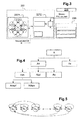
- a particular example, illustrated on the Figure 3 is the case of a completely connected state transition model, namely, where each state can pass to any other state.
- connection matrix for a fully connected architecture is shown in Table 1 below. ⁇ u> Table 1 ⁇ / u> state 0 1 2 ... N k S0 1 1 1 1 1 1 S1 1 1 1 1 1 S2 1 1 1 1 1 . . 1 1 1 1 1 . SN 1 1 1 1 1 1
- a value 0 in a cell of the matrix has the effect of prohibiting a direct transition between two states. This can be used as a means of security by prohibiting transitions between specific pacing configurations. For example, in the case of vagus nerve stimulation (VNS), a too abrupt change in the injected current can cause undesirable effects, and such a change can be avoided by setting the corresponding cell (s) to a value of zero. the connection matrix.
- VNS vagus nerve stimulation
- the state transition calculator is dedicated to the determination of optimal transitions between states, so as to lead to an optimization of the configuration of the neurostimulation parameters by minimizing the error between the PVLcurrent and PVLcible.
- Transitions between states are defined at specific times that are called here "events”. These events may be regular in time (for example, every minute), or synchronously distributed to a physiological activity (for example at each heartbeat), depending on a given situation (for example when the patient is asleep) , with low HRV heart rate variability) or any combination of such situations.
- the state transition calculator 2272 determines the most appropriate state transition, applying a state transition algorithm based on a transition matrix T as we will now see.
- This table shows the state S0 which corresponds to the immediate stopping of the neurostimulation under certain conditions, for example during the occurrence of undesirable events (typically cough, pain, cardiac arrhythmia, etc.). It is a priority condition (denoted by Cond P) which leads to this state, where the neurostimulation parameters are brought to 0.
- Cond P a priority condition which leads to this state, where the neurostimulation parameters are brought to 0.
- the condition P has priority over all the others.
- transition matrix for the deterministic algorithm is composed of a set of conditions that can be implemented as rules.
- the invention also makes it possible to process transitions probabilistically.
- an example of a stochastic type transition matrix T may be the following: ⁇ u> Table 3 ⁇ / u> Event t + 1 state S1 S2 S3 ... S N-2 S N-1 S N S1 at 1.1 a 1,2 at 1.3 at 1, ... a 1, N-2 a 1, N-1 a 1, N S2 a 2.1 at 2.2 a 2,3 at 2, ... a 2, N-2 a 2, N-1 a 2, N S3 at 3.1 3.2 3.3 at 3, ... a 3, N-2 a 3, N-1 a 3, N t ...
- the Figure 4 shows the hierarchy between a number of examples of transition algorithms A which will be described later, with a stochastic algorithm As , a deterministic algorithm Ad , and in the latter category a sequential transition algorithm Ads , which can be of Adspf or Adpv variable pitch type, an algorithm based on the Abd dichotomy, and an optimal algorithm Ao .
- Table 4 gives an example of a connection matrix C for a sequential type state transition algorithm with a paused stop state: ⁇ u> Table 4 ⁇ / u> state 0 1 2 3 4 ... N-1 NOT S0 1 1 0 0 0 0 0 0 0 0 S1 1 1 1 0 0 0 0 0 S2 1 1 1 1 0 0 0 0 S3 1 0 1 1 1 0 0 0 0 S4 1 0 0 1 1 1 0 0 . 1 . - - - - - - - . S N-1 1 0 0 0 0 1 1 1 S N 1 0 0 0 0 0 1 1 1
- each state of the state transition model is connected to S0, to itself and to its adjacent states, as shown in FIG. Figure 5 .
- the state S0 corresponds to an immediate stop of the neurostimulation in the case of undesirable events, as previously described.
- states of the state transition model are categorized according to the effect they cause on the physiological variable (s) to be regulated.
- the states S0 to S4 given above by way of example (2) are an example of states categorized with respect to the regulation of the RR interval and the temporal variation (first derivative) of the cardiac pressure.
- step of 1 corresponds to the transition from a state i to an immediately adjacent state.
- the counter allows an update of the status of all events, for example every 5 heart cycles.
- FIG. 7 An example of how this algorithm should operate to regulate the instantaneous RR interval of a patient is illustrated on the Figure 7 .
- the target value of the RR interval is set at 498 ms and the d value is set at 5 cardiac cycles.
- the result of applying the algorithm is shown on the Figure 8 .
- the box 95 determines the value of the step.
- the larger the value of e then the greater the step value.
- the smaller the e value the smaller the step value.
- the step value may result from the application of a non-linear function to the value of the error e (for example of the sigmoid type) ; in other embodiments, the step value may result from the application of a linear function to the value of the error e limited to the minimum and maximum limits of the step.
- the state transition calculator 2272 operates according to a dichotomous principle, as illustrated in FIG. Figure 10 .
- the state transition calculator 2272 uses an expected response value RS previously stored in the state transition model 2271 (it will be recalled here that in the various embodiments, each state of the transition model status 601 contains the expected answer (s) for the state parameters, see list (1) above).
- the state transition calculator 2272 searches for the expected minimum RS response for which the next condition of the controller error PVLcible PVLcourant > thresholdCL (tested at box 105) is completed and where thresholdCL is defined by an expert.
- a state S0 can be used for security conditions.
- connection matrix C as shown in Table 1 can be used with the deterministic and sequential step- change algorithm Adspv, with the deterministic transition algorithm based on dichotomous Abd and with the optimal deterministic transition algorithm Ao.
- a stochastic approach according to this embodiment aims to address some of the uncertainty related to this complexity by applying a transition probability to a given state.
- probabilistic graphs may be used to calculate the state transition to be selected from the state transition model.
- weights are then probabilities, namely real numbers between 0 and 1, and that a probabilistic graph shows the possible states of the system and the transition probabilities from one state to another (weight of the arcs).
- the Figure 11a is an example of a second-order (two-state) probabilistic graph.
- the Figure 11b is an example of a probabilistic graph of order three.
- the Figure 11c shows an example of a non-probabilistic graph, since the sum of the weights of arcs starting from the state S1 is equal to 0.9 and not to 1.
- a Markov matrix is used to determine the optimal transitions to reach the target level of the physiological variable, as described in Table 3, where a i, j represents the probability of a transition of one state to another in the state transition model.
- a state S0 can be provided for safe conditions.
- the probabilities a i, j are calculated during a learning phase, using algorithms of a Hidden Markov Model (HMM).
- HMM Hidden Markov Model
- the Baum-Welch algorithm forward-backward ) makes it possible to estimate the set of parameters of the state transition model (here a HMM) iteratively, to from a learning database.
- the Viterbi algorithm calculates the sequence of states that will most probably correspond, while the forward algorithm calculates the probability of a particular sequence of observations. observations.
- the target value of the RR interval is set to 500ms.
- HMM state transition model
- the transitions are a function of the probabilities associated with the transition matrix T.
- the states may vary in a probabilistic manner, even if the target physiological value remains constant. This probabilistic behavior may be particularly important in physiological or clinical applications because the underlying processes are complex and therefore have natural variability that can be represented by a random process.
- Neurostimulation therapy is then adapted to follow these variations with different temporal resolutions.
- Time multiresolution is provided in this embodiment, as shown in FIG. Figure 13 by providing a plurality of state transition control devices, respectively 227 1 , 227 2 ... 227 K , each device operating with a different temporal resolution and with state transition model parameters and different algorithms, such as than previously defined.
- control system is composed of two state transition control devices 227 1 and 227 2 , one providing regulation of a physiological variable in the short term (denoted PV1), and the other providing regulation.
- a long-term physiological variable denoted PV2
- VNS vagal nerve stimulation
- the effect of a given VNS stimulation may change over time, as shown in Figure 14 .
- M0 represents the effect of the VNS stimulation on the PV1 variable during implantation
- M3 represents the effect of the VNS on the PV1 variable three months after implantation
- M6 represents the effect of the stimulation.
- VNS on variable PV1 six months after implantation.
- the three curves illustrated on the Figure 14 were obtained with the same five successive VNS stimulation parameter configurations.
- a first control device is used to regulate the variable PV1
- the second control device estimates the effect of the stimulation on the variable PV1 and compensates for the variations of this effect on the time scale M0, M3, M6.
- the Figure 15 shows an example of how the control system can be implemented, the control devices 227 1 , and 227 2 delivering instructions O1 and 02 which are merged at the level of the fusion module 229 to determine the current state to which to make a transition.
- this merge consists of a multiplication.
- the Figure 16a shows in the upper part the response of variable PV1 when using a single control device.
- the Figure 16b shows in the upper part the response of variable PV1 when using two control devices.
- the different curves correspond to different moments (in months, days, years or other) to which a PVLcible value of the physiological variable PV1 is established.
- the output of the control device 227 1 leads to stimulation parameters of similar values to reach the target, due to the compensation provided by the second control device 227 2 .
- the two-controller approach provides better accuracy and lower convergence times, while using a simpler state transition model (lower number of states).
- a particular case of multi-controller control is the case where one or more probabilistic state transition models are used to improve accuracy around a PVL-target value area and one or more transition models. Deterministic states are used to improve the speed of convergence (the time needed to reach the target).
- each control device will have a different probabilistic or deterministic model and the fusion module 229 will define the final stimulation parameters.
- VNS therapy ie different pacing parameters and therefore different states of the state transition model
- This learning phase can take a long time, and in some cases it is not possible to implement it.
- a generalized VNS pacing pattern in the form of a general state table
- a general state table derived from the analysis of a database of a population similar to that of the treated patient is used.
- this general state table can be used as an initial state table, and a patient specific learning phase can be performed to improve the accuracy of the control system.
- This embodiment is advantageously based on a closed loop approach incorporating patient-specific properties.
- state transition control device In order to implement the state transition control device (s), it is first necessary to identify the main parameters of the associated state transition model from population data, or in a patient-specific manner.
- control device architecture and the state transition model parameters are defined (step 171) by implementing a learning phase 172 which can be based on a population ( step 173) or patient-specific (step 174).
- each state transition control device is characterized by defining the number of states of the model and by the desired interstate connections (as defined in the matrix C). These definitions are based on a needs analysis. Once this structure is defined, the parameters of the state transition algorithm (mainly the stimulation parameter set P Mk, Nk, k and the values reached RS Qk, Nk, k for each state, as well as the matrix of transitions T, must be determined.
- the parameters of the state transition algorithm mainly the stimulation parameter set P Mk, Nk, k and the values reached RS Qk, Nk, k for each state, as well as the matrix of transitions T.
- the learning phase consists of stimulating the patient (or several patients) with a set of stimulation parameters and analyzing the values reached with physiological variables with these sets of parameters. From these observations, an analysis is carried out in order to define the structure and the parameters of each state transition model and in particular the C and T matrices. Moreover, this learning phase makes it possible to detect parameters which provoke side effects, to exclude them from the state transition model.
- a population-based learning phase is illustrated in Figure 18. This approach is based on the analysis of a database of a population, typically characteristic of the targeted pathology, including records of physiological variables. interest, for different patients, and with different stimulation parameters for each patient.
- the Figure 18 illustrates the complete organization chart of this population-based learning phase.
- FIG. 19 The block diagram of a patient-specific learning phase is illustrated on the Figure 19 .
- this patient-specific learning procedure can be applied in an intraoperative or post-operative setting, typically during control visits.
- the patient is stimulated using a set of pacing parameters, with a scan of the parameter values, and the effect on the PVL variables (or on a main variable involved) is measured.
- the settings. P Mk, Nk, k and the values reached RS Qk, Nk, k for each state (constituting the set Sn k, k), as well as the matrix T, are obtained by analyzing these data.
- each control device at the beginning of a therapy may be non-optimal at a later time, because the physiological and physical state of the patient is constantly changing due to various predictable factors such as as circadian and seasonal rhythms, or unpredictable as changes in the environment (temperature, sociality %), chronic or acute diseases (seasonal flu, cancer, heart failure %), behavior (diet, activity, alcohol consumption, smoking %), adverse events.
- the evolution of the patient's pathology may require regular updating of the main parameters of the state transition model.
- This updating of the parameters of the control device can also be implemented depending on the activity of the patient (exercise, sleep ).
- this adaptive approach it is possible to avoid or reduce medical visits and to deliver the optimal therapy permanently.
- the implantable device will achieve the actual effect on the patient using the physiologic level-level calculator 225. This effect is supposed to be close to the expected value RS1.
- the Figure 25 illustrates in detail the architecture of this adaptive configuration.
- the PV value measurements delivered by the unit 21 are used to calculate different levels of PVL physiological values using the PVL level calculator 225 (for example and without limitation the interval RR, maximum peaks of blood pressure variation noted (dP / dt) max , physical activity).
- These variables are introduced into the proposed control system, composed of one or more state transition control devices, here two devices 227 1 and 227 2 .
- Each state transition control device generates a set of possible parameters depending on the PVL level received from the computer.
- An activity sensor module 251 detects the activity of the patient during the day, for example by qualifying it on different levels of "rest”, “on”, “sleep", “power”. This activity information is used by a parameter reconfiguration module 252 implementing a dedicated reconfiguration algorithm and the parameter fusion management module 229 to adapt the state transition model and the processing. to the activity of the patient.
- the parameter merge management module selects the optimal set of VNS pacing parameters from a set of possible sets of parameters to achieve short-term and long-term physiological targets. It can be decided that in certain levels of patient activity, the VNS is not delivered (state S0), for example during "sleep".
- An analysis module 253 and the parameter reconfiguration module receive the current state CS (defining the current parameter set) and the level of the PVL physiological variable obtained with this state, and determine whether the state transition model must be reconfigured or not.
- an advantageous characteristic of this adaptive approach is that the analysis module and the parameter reconfiguration module are able to detect the parameter configurations (states) causing side effects. If a condition causes side effects (this effect can be detected as previously by the available sensors), then the parameter reconfiguration module rejects this state (makes it unavailable), or modifies the values of the VNS parameters of this state.
- the parameter reconfiguration module 252 adapts the state transition model if necessary, according to approaches as will be described hereinafter.
- Another application of this adaptive approach may include the activation of preprogrammed VNS pacing protocols, resulting in an update of the expected responses for each state (RS Qk, Nk, k ), either on a regular basis over time, or the occurrence of any specified event, as will be described later.
- the Figure 26 shows the flowchart of the proposed adaptive approach.
- an estimation of the remote parameters is carried out in an external system 270 comprising the parameter reconfiguration module 252 and the analysis module 253, as illustrated in FIG. Figure 27 .
- This estimate is based on a scan of the parameters and an analysis of its effects, as described above. This estimate can be made per-or post-operatively during a follow-up session, using a remote analysis module.
- an adaptive estimation of the parameters is carried out in an integrated manner, that is to say that the updating of the RS values and the reorganization of the transition matrix T are carried out within the implantable device itself, which implies that the analysis module 253 and the reconfiguration module 252 are embedded in the implantable device.
- the implantable device is here self-adaptive and autonomously realizes learning of typical values.
- the adaptive parameter estimation feature is a refinement of the state transition control system described in the foregoing, whether implemented on a deterministic, stochastic basis or on a set of control devices combining deterministic and stochastic approaches.
- the adaptation of the state transition model can be performed at different temporal resolutions such as, but not limited to, n times a day, n times a week, n times a month, n times a year, on a programmed basis by the practitioner with a corresponding follow-up.
- the adaptation of the state transition model can be carried out with different temporal resolutions such as, in a nonlimiting manner, n times per hour, n times per day, daily, once a week, once a month, once a year.
- the embodiment of the Figure 28 can be used to adapt control devices dedicated to the regulation of physiological variables in the short term (eg RR interval, peaks of blood pressure variation (dP / dt) max , physical activity) and to the regulation of long-term variable physiological variables (eg HR heart rate, HRV heart rate variability).
- physiological variables in the short term eg RR interval, peaks of blood pressure variation (dP / dt) max , physical activity
- dP / dt peaks of blood pressure variation
- HR heart rate HRV heart rate variability
- the embodiment of the Figure 27 can be used to adapt the state transition control devices dedicated to the regulation of physiological variables in the long term.
Abstract
Ce système comprend un dispositif de stimulation (28) tel qu'une sonde de stimulation du nerf vague, et des moyens de commande du dispositif de stimulation selon un jeu de paramètres de stimulation. Une mémoire contient un modèle de transition d'état (2272), avec pour chaque état un jeu défini de paramètres de stimulation et au moins une réponse attendue lors de l'application d'une stimulation avec ces paramètres. Une matrice détermine des règles de transition entre états basées sur des niveaux physiologiques mesurés par rapport à des niveaux cibles. Un dispositif de commande de transition d'état (2271) détermine de façon organisée dans le temps des éventuelles transitions entre états en fonction de l'application des règles sur les niveaux physiologiques obtenus en réponse à l'application de la stimulation avec les paramètres de l'état courant, une transition d'un état courant vers un nouvel état provoquant un change-ment correspondant dans le jeu de paramètres utilisé pour la stimulation.The system includes a stimulation device (28) such as a vagus nerve stimulation probe, and control means of the stimulation device according to a set of stimulation parameters. A memory contains a state transition model (2272), with for each state a defined set of pacing parameters and at least one expected response when applying pacing with these parameters. A matrix determines transition rules between states based on physiological levels measured against target levels. A state transition controller (2271) determines in an organized manner over time any transitions between states based on the application of the rules on the physiological levels obtained in response to the application of the stimulation with the parameters of the state. the current state, a transition from a current state to a new state causing a corresponding change in the set of parameters used for the stimulation.
Description
L'invention concerne d'une façon générale les dispositifs destinés à appliquer sur des organes une stimulation à des fins thérapeutiques.The invention generally relates to devices for applying stimulation to organs for therapeutic purposes.
Elle est notamment applicable aux "
Quelle que soit la pathologie à traiter, une thérapie de stimulation vise en général à maximiser les effets thérapeutiques, tout en minimisant les effets secondaires, ainsi que la consommation d'énergie dans le cas où la stimulation est mise en oeuvre dans un dispositif implantable autonome.Whatever the pathology to be treated, a stimulation therapy is generally intended to maximize the therapeutic effects, while minimizing the side effects, as well as the energy consumption in the case where the stimulation is implemented in an autonomous implantable device .
Cette stimulation doit en même temps tenir compte de la dynamique de la pathologie résultant par exemple d'une altération du système nerveux autonome (ANS, Autonomic Nervous System), d'un remodelage cardiaque ou de l'ANS, ainsi que de la réponse à la thérapie (habituation, modification du couplage électrode-nerf vague dans le cas de la stimulation du nerf vague (VNS, Vagus Nerve Stimulation).This stimulation must at the same time take into account the dynamics of the pathology resulting for example from an alteration of the autonomic nervous system (ANS, Autonomic Nervous System ), a cardiac remodeling or the ANS, as well as the response to therapy (habituation, modification of the electrode-vagus nerve coupling in the case of vagus nerve stimulation (VNS, Vagus Nerve Stimulation ).
Ainsi l'application d'une stimulation optimale est un problème complexe, imparfaitement traité à l'heure actuelle bien que représentant l'une des priorités les plus hautes dans les progrès de la neurostimulation.Thus the application of optimal stimulation is a complex problem, imperfectly treated at the present time, although it represents one of the highest priorities in the progress of neurostimulation.
Il existe à l'heure actuelle des approches de commande de la stimulation en boucle fermée, qui peuvent être classées en deux familles :
- 1) les approches à base de règles, telles que celles décrites dans les
US 7 783 349 B2US 7 509 166 B2US 2012/245656 A1 WO 2011/137029 A - 2) les approches à base d'une fonction de transfert linéaire ou non linéaire des variables de contrôle, telles que celles décrites par exemple dans le
EP 1 102 607 A1
- 1) rule-based approaches, such as those described in
US 7,783,349 B2 US 7,509,166 B2 US 2012/245656 A1 WO 2011/137029 A - 2) the approaches based on a linear or non-linear transfer function of the control variables, such as those described for example in the
EP 1 102 607 A1
La première approche a deux limites majeures : i) il est difficile de définir des règles optimales pour un patient donné et ii) ces règles reposent sur la définition de seuils, qui peuvent varier en fonction de la variabilité inter-et intra-patient.The first approach has two major limitations: i) it is difficult to define optimal rules for a given patient and ii) these rules are based on the definition of thresholds, which can vary according to inter-and intra-patient variability.
Les principales limites de la deuxième approche sont quant à elles i) la complexité de calcul nécessaire pour mettre en oeuvre les dispositifs de commande, et ii) le grand nombre de données nécessaires pour ajuster les paramètres du dispositif de commande.The main limitations of the second approach are i) the computational complexity necessary to implement the control devices, and ii) the large number of data needed to adjust the parameters of the control device.
Il existe par ailleurs d'autres méthodes pour estimer un ensemble de règles spécifiques aux patients [1,2], d'inférer des ajustements inter- ou intra-patients [3], et pour réduire la complexité des calculs à effectuer dans le dispositif de commande [4, 5]. Ces approches restent toutefois théoriques et difficiles à mettre en oeuvre et à intégrer dans les dispositifs implantables actifs, dotés d'une puissance de traitement numérique limitée. Les références pertinentes sont :
- [1]
A. Aarabi, and H. Bin, "Seizure prediction in intracranial EEG: A patient-specific rule-based approach", Engineering in Medicine and Biology Society, EMBC, 2011 Annual International Conference of the IEEE, 2566 - 2569, Boston, MA - [2]
I. Capel, M. Rigla, G. García-Sáez, A. Rodríguez-Herrero, B. Pons, D. Subías, F. García-García, M. Gallach, M. Aguilar, C. Pérez-Gandía, E. J. Gômez, A. Caixàs, and M. E. Hernando, "Artificial Pancraas Using a Personalized Rule-Based Controller Achieves Overnight Normoglycemia in Patients with Type 1 Diabetes", Diabetes Technol Ther., Vol. 16(3): 172-179 (2014 - [3]
F. Porée, A. Kachenoura, G. Carrault, R. D. Molin, P. Mabo, and A. I. Hernàndez, "Surface Electrocardiogram Reconstruction From Intra-cardiac Electrograms Using a Dynamic Time Delay Artificial Neural Network", Biomedical Engineering, IEEE Transactions on, Vol. 60, 106-114, (2013 - [4]
H. M. Romero Ugalde, J.-C. Carmona, V. M. Alvarado and J. Reyes-Reyes, "Neural Network Design and Model Reduction Approach for Black Box Non Linear System Identification with Reduced Number of Parameters", Neurocomputing, Vol. 101, 170-180 (2013 - [5]
M. Löhning, M. Reble, J. Hasenauer, S. Yu, F. Allgöwer, "Model predictive control using reduced order models: Guaranteed stability for constrained linear systems", Journal of Process Control, Vol. 24 (11), 1647-1659, (2014
- [1]
A. Aarabi, and H. Bin, "Seizure prediction in intracranial EEG: A patient-specific rule-based approach," EMBC, International Conference of the IEEE, 2566 - 2569, Boston, MA - [2]
I. Capel, M. Rigla, G. García-Sáez, A. Rodríguez-Herrero, B. Pons, D. Subías, F. García-García, M. Gallach, M. Aguilar, C. Pérez-Gandía, EJ Gomez A. Caixas, and ME Hernando, "Artificial Pancraas Using a Personalized Rule-Based Controller Achieves Overnight Normoglycemia in Patients with Type 1 Diabetes," Diabetes Technol Ther., Vol. 16 (3): 172-179 (2014) - [3]
F. Poree, A. Kachenoura, Carrault G., Molin RD, Mabo P., and Al Hernandez, "Surface Electrocardiogram Reconstruction From Intra-cardiac Electrograms Using a Dynamic Time Delay Artificial Neural Network," Biomedical Engineering, IEEE Transactions on, Vol. . 60, 106-114, (2013 - [4]
HM Romero Ugalde, J.-C. Carmona, VM Alvarado and J. Reyes-Reyes, "Neural Network Design and Model Reduction Approach for Black Box Non Linear System Identification with Reduced Number of Parameters", Neurocomputing, Vol. 101, 170-180 (2013) - [5]
M. Löhning, M. Reble, J. Hasenauer, Yu Yu, F. Allgöwer, "Guaranteed stability for Constrained linear systems ", Journal of Process Control, Vol 24 (11), 1647-1659, (2014)
Enfin, une autre limitation majeure des approches existantes concerne la constante de temps de la commande en boucle fermée, qui est généralement figée sur une unique échelle de temps prédéfinie (par exemple à chaque battement cardiaque, chaque minute, chaque jour, etc.), en particulier dans le cas où les variables commandées sont les résultats des processus qui s'entremêlent sur différentes échelles temporelles, comme en physiologie.Finally, another major limitation of the existing approaches concerns the time constant of the closed-loop control, which is usually fixed on a single predefined time scale (for example at each heartbeat, every minute, every day, etc.). especially in the case where the ordered variables are the results of the processes which intermingle on different temporal scales, as in physiology.
La présente invention vise à pallier ces limitations de l'état de la technique et à proposer une commande de stimulation qui ne nécessite que des moyens de calcul limités, tout en étant extrêmement souple et apte à ajuster de façon très fine la stimulation à la situation physique et/ou physiologique observée.The present invention aims to overcome these limitations of the state of the art and to propose a stimulation control which requires only limited calculation means, while being extremely flexible and able to very precisely adjust the stimulation to the situation. physical and / or physiological observed.
Plus précisément, l'invention propose à cet effet un système de traitement par stimulation, comprenant :
- un dispositif de stimulation tel qu'un générateur d'impulsions connecté à une ou plusieurs électrodes aptes à être placées sur ou à proximité d'un nerf du système nerveux autonome ;
- au moins un capteur de signaux physiologiques et/ou physiques et des unités de traitement de ces signaux, capables de fournir au moins un niveau physiologique/physique courant ; et
- des moyens de commande du dispositif de stimulation selon un jeu de paramètres de stimulation.
- a stimulation device such as a pulse generator connected to one or more electrodes adapted to be placed on or near a nerve of the autonomic nervous system;
- at least one physiological and / or physical signal sensor and processing units for these signals, capable of providing at least one current physiological / physical level; and
- control means of the stimulation device according to a set of stimulation parameters.
De façon caractéristique de l'invention, ce système comprend au moins un module de contrôle comportant :
- un modèle de transition d'états, ledit modèle comprenant une matrice de transition et une matrice de connexion, les états dudit modèle étant caractérisés chacun par un jeu de valeurs des paramètres de stimulation, associé à au moins une réponse physiologique/physique attendue lors de l'application d'une stimulation avec ces paramètres ; et
- un dispositif de commande de transition d'états déterminant de façon organisée les transitions d'un état courant vers un nouvel état, provoquant un changement correspondant du jeu de valeurs des paramètres utilisés pour la stimulation, d'un jeu de paramètres courant (Pi) vers un nouveau jeu de paramètres.
- a state transition model, said model comprising a transition matrix and a connection matrix, the states of said model being each characterized by a set of values of the stimulation parameters, associated with at least one physiological / physical response expected during the application of stimulation with these parameters; and
- a state transition control device that organically determines the transitions from a current state to a new state, causing a corresponding change in the parameter value set used for pacing, from a current parameter set (Pi) to a new set of parameters.
Dans une première forme de mise en oeuvre, le modèle de transition d'états est de type déterministe, les matrices de transition étant connues à l'initialisation du système.In a first embodiment, the state transition model is of deterministic type, the transition matrices being known at the initialization of the system.
Selon diverses caractéristiques subsidiaires avantageuses :
- le dispositif de commande est apte à détecter une situation physique et/ou physiologique anormale et à réaliser une transition vers un état d'absence de stimulation en réponse à cette détection ;
- le dispositif de commande est apte à déterminer d'éventuelles transitions entre états de façon régulière et prédéterminée dans le temps ;
- le dispositif de commande est apte à déterminer d'éventuelles transitions entre états en réponse à la survenue d'un ou plusieurs évènements prédéterminés ;
- le modèle de transition déterministe est séquentiel, les différents états étant ordonnés selon l'effet qu'ils provoquent sur le patient, une transition à partir d'un état ne pouvant être effectuée qu'avec un pas donné, fixe ou variable, vers un état d'ordre supérieur, vers un état d'ordre inférieur, ou vers le même état ;
- le modèle de transition déterministe est à base de dichotomie entre états de niveau minimal et de niveau maximal ;
- le modèle de transition déterministe est optimisé, le dispositif de commande déterminant l'état contenant la réponse la plus basse pour laquelle la différence entre le niveau physiologique mesuré et le niveau physiologique cible est inférieure à un seuil donné ;
- the control device is adapted to detect an abnormal physical and / or physiological situation and to make a transition to a state of absence of stimulation in response to this detection;
- the control device is able to determine possible transitions between states regularly and predetermined in time;
- the control device is able to determine possible transitions between states in response to the occurrence of one or more predetermined events;
- the deterministic transition model is sequential, the different states being ordered according to the effect they cause on the patient, a transition from a state can only be performed with a given step, fixed or variable, to a state of higher order, to a state of inferior order, or to the same state;
- the deterministic transition model is based on a dichotomy between states of minimal level and maximum level;
- the deterministic transition model is optimized, the control device determining the state containing the lowest response for which the difference between the measured physiological level and the target physiological level is below a given threshold;
Dans une seconde forme de mise en oeuvre, la ou les matrices mémorisées correspondent à un modèle de transition stochastique, chaque cellule contenant une valeur de probabilité de transition d'un état initial vers un nouvel état, et la somme des valeurs de probabilités des transitions possibles à partir d'un état donné vers tout nouvel état étant égale à 1. Selon diverses caractéristiques subsidiaires avantageuses :
- le modèle de transition d'état est un Modèle de Markov Caché (Hidden Markov Model) ;
- le dispositif de commande est apte à détecter une situation physique et/ou physiologique anormale et à réaliser une transition vers un état d'absence de stimulation en réponse à cette détection.
- the state transition model is a Hidden Markov Model ;
- the control device is adapted to detect an abnormal physical and / or physiological situation and to make a transition to a state of absence of stimulation in response to this detection.
Le niveau physiologique et physique peut être notamment déterminé à partir de l'une des variables physiologiques ou physiques suivantes : fréquence cardiaque, variabilité du rythme sinusal, pression artérielle, contractilité cardiaque, activité physique, température, mouvements, fréquence respiratoire, ou toute combinaison de ces variables.The physiological and physical level may be determined in particular from one of the following physiological or physical variables: heart rate, sinus rhythm variability, blood pressure, cardiac contractility, physical activity, temperature, movement, respiratory rate, or any combination of these variables.
On va maintenant décrire un exemple de mise en oeuvre de la présente invention, en référence aux dessins annexés où les mêmes références désignent d'une Figure à l'autre des éléments identiques ou fonctionnellement semblables.
- La
Figure 1 illustre schématiquement l'architecture d'un système de stimulation à boucle fermée auquel s'applique l'invention. - La
Figure 2 représente plus en détail l'architecture du système de commande à transition d'état selon l'invention. - La
Figure 3 illustre encore plus en détail ce système et un modèle particulier de transition d'état. - La
Figure 4 illustre différents algorithmes pouvant être mis en oeuvre dans un dispositif de commande de transition d'état. - La
Figure 5 illustre graphiquement un mode particulier de transition entre états. - La
Figure 6 illustre l'architecture d'un dispositif de commande de transition d'état déterministe et séquentiel à pas fixe. - La
Figure 7 illustre les changements d'état courant en réponse à l'action de ce dispositif de commande. - La
Figure 8 illustre un autre mode de changement d'état courant et l'allure correspondante d'un niveau physiologique réel par rapport à un niveau physiologique cible. - La
Figure 9 illustre l'architecture d'un dispositif de commande de transition d'état déterministe et séquentiel à pas variable. - La
Figure 10 illustre l'architecture d'un dispositif de commande de transition d'état déterministe à base dichotomique. - La
Figure 10bis illustre l'architecture d'un dispositif de commande de transition d'état déterministe optimisé. - La
Figure 11 illustre des transitions entre états contrôlées par un modèle de transition stochastique. - La
Figure 12 représente l'évolution des états et l'évolution du niveau physiologique réel par rapport à un niveau physiologique cible avec ce modèle stochastique. - La
Figure 13 illustre l'architecture d'un dispositif de commande de transition d'état à résolutions temporelles multiples. - La
Figure 14 illustre différentes réponses à une même stimulation en réponse à des évolutions physiologiques de long terme, à des instants espacés également sur le long terme. - La
Figure 15 illustre une combinaison (ou fusion) de consignes de transition d'état délivrées par deux dispositifs de commande de transition d'état différents d'un même système. - La
Figure 16 illustre comparativement les comportements des réponses à des changements d'états respectivement avec un seul dispositif de commande de transition d'état sur le court terme et avec deux dispositifs de commande de transition d'état respectivement sur le court terme et sur le long terme. - La
Figure 17 illustre différentes possibilités d'un mécanisme d'apprentissage pour un dispositif de commande à transition d'état. - La
Figure 18 est un organigramme d'une approche d'apprentissage basée sur une population de patients. - La
Figure 19 est un organigramme simplifié d'un mécanisme d'apprentissage spécifique à un patient. - La
Figure 20 est un organigramme simplifié illustrant la combinaison d'un apprentissage basé sur une population de patients et d'un apprentissage spécifique à un patient. - La
Figure 21 est un organigramme détaillé de cette combinaison. - La
Figure 22 illustre les paramètres de stimulation pour un ensemble d'états. - La
Figure 23 est un graphe montrant l'évolution dans le temps d'un niveau physiologique et les transitions d'états correspondantes. - La
Figure 24 représente des écarts de niveau physiologique, représentant l'effet de la stimulation en utilisant les paramètres associés à chaque état, respectivement avant et après un tri d'états par rapport à l'effet obtenu. - La
Figure 25 illustre l'architecture d'un système de commande à transition d'état adaptatif. - La
Figure 26 est un organigramme d'une telle commande adaptative. - La
Figure 27 illustre l'implémentation de l'architecture de laFigure 25 dans le cadre d'une estimation de paramètres déportée. - La
Figure 28 illustre l'implémentation de l'architecture de laFigure 25 dans le cadre d'une estimation de paramètres intégrée.
- The
Figure 1 schematically illustrates the architecture of a closed loop stimulation system to which the invention applies. - The
Figure 2 shows in greater detail the architecture of the state transition control system according to the invention. - The
Figure 3 further illustrates this system and a particular state transition model. - The
Figure 4 illustrates different algorithms that can be implemented in a state transition control device. - The
Figure 5 Graphically illustrates a particular mode of transition between states. - The
Figure 6 illustrates the architecture of a deterministic and sequential state transition control device with fixed pitch. - The
Figure 7 illustrates the current state changes in response to the action of this controller. - The
Figure 8 illustrates another mode of current state change and the corresponding pace of a real physiological level with respect to a target physiological level. - The
Figure 9 illustrates the architecture of a deterministic and sequential variable pitch state control device. - The
Figure 10 illustrates the architecture of a dichotomous deterministic state transition control device. - The
Figure 10bis illustrates the architecture of an optimized deterministic state transition control device. - The
Figure 11 illustrates transitions between states controlled by a stochastic transition model. - The
Figure 12 represents the evolution of states and the evolution of the actual physiological level with respect to a target physiological level with this stochastic model. - The
Figure 13 illustrates the architecture of a state transition control device with multiple temporal resolutions. - The
Figure 14 illustrates different responses to the same stimulation in response to long-term physiological changes, at times spaced also in the long term. - The
Figure 15 illustrates a combination (or merge) of state transition instructions issued by two different state transition control devices of the same system. - The
Figure 16 comparatively illustrates the behavior of responses to state changes respectively with a single short-term state transition controller and with two short-term and long-term state transition control devices. - The
Figure 17 illustrates different possibilities of a learning mechanism for a state transition controller. - The
Figure 18 is a flowchart of a learning approach based on a patient population. - The
Figure 19 is a simplified flowchart of a patient-specific learning mechanism. - The
Figure 20 is a simplified flowchart illustrating the combination of learning based on a patient population and patient-specific learning. - The
Figure 21 is a detailed flowchart of this combination. - The
Figure 22 illustrates the pacing parameters for a set of states. - The
Figure 23 is a graph showing the evolution over time of a physiological level and the transitions of corresponding states. - The
Figure 24 represents physiological level deviations, representing the effect of the stimulation using the parameters associated with each state, respectively before and after a sorting of states with respect to the effect obtained. - The
Figure 25 illustrates the architecture of an adaptive state transition control system. - The
Figure 26 is a flow chart of such adaptive control. - The
Figure 27 illustrates the implementation of the architecture of theFigure 25 as part of a remote parameter estimation. - The
Figure 28 illustrates the implementation of the architecture of theFigure 25 as part of an integrated parameter estimation.
On va maintenant décrire un exemple de réalisation du dispositif de l'invention.An embodiment of the device of the invention will now be described.
Le procédé de l'invention est mis en oeuvre par des moyens principalement logiciels, au moyen d'algorithmes appropriés exécutés par un micro-contrôleur ou un processeur numérique de signal. Pour la clarté de l'exposé, les divers traitements appliqués seront décomposés et schématisés par un certain nombre de blocs fonctionnels distincts présentés sous forme de circuits interconnectés, mais cette représentation n'a toutefois qu'un caractère illustratif, ces circuits comprenant des éléments communs et correspondant en pratique à une pluralité de fonctions globalement exécutées par un même logiciel.The method of the invention is implemented by mainly software means, by means of appropriate algorithms executed by a microcontroller or a digital signal processor. For the sake of clarity, the various treatments applied will be decomposed and schematized by a number of distinct functional blocks presented in the form of interconnected circuits, but this representation is however only illustrative, these circuits comprising common elements. and corresponding in practice to a plurality of functions globally executed by the same software.
On notera à titre liminaire que dans la mesure du possible, les mêmes signes de référence sont utilisés d'une figure à l'autre pour désigner les mêmes éléments.It should be noted that, as far as possible, the same reference signs are used from one figure to another to designate the same elements.
En référence tout d'abord à la
Le dispositif est divisé en trois sous-systèmes principaux :
- i) un générateur d'impulsions implantable
ou externe 20 comprenant les éléments suivants :- un module de traitement de données sous forme d'un microcontrôleur ou microprocesseur 27, apte à communiquer avec d'autres modules du dispositif pour recevoir ou envoyer des données et des commandes de contrôle ;
un module 21 composé d'un ensemble de capteurs et de moyens de traitement de données, apte à enregistrer, à stocker et à traiter les données provenant des capteurs ; ces moyens de traitement comprennent de façon non limitative des amplificateurs, des convertisseurs analogique-numérique, des filtres, des compresseurs de données, des fonctions de transfert ;- un module de commande en boucle fermée 22 destiné à fournir de façon dynamique et auto-adaptative les paramètres d'une stimulation optimale, en fonction d'un ensemble de valeurs cibles pour le ou chaque niveau de variable physiologique ou physique, ci-après "PVL" (Physical/Physiological Variable Level). On décrira ce système dans la suite en référence à la
Figure 2 ; - un module de mémoire 26 apte à stocker les paramètres de fonctionnement des différents modules 21 (acquisition des signaux des capteurs et traitement des données), 22 (calcul PVL), 27, 28 (stimulateur), notamment les valeurs cibles des PVL souhaitées, ci-après "PVLcible", pour le fonctionnement de la boucle de contrôle, les données calculées au niveau des différents modules, et des données pour le suivi clinique, sur des échelles de temps différentes ;
- un ou plusieurs capteurs internes 29, par exemple un accéléromètre et/ou un capteur de température ;
- un dispositif de
stimulation 28 appliquant une stimulation à unestructure physiologique 12, ici le corps humain ; dans les exemples décrits ci-dessous, le dispositif 28 est un module électronique de stimulation du nerf vague ; - un module de télémétrie 30 apte à communiquer avec un dispositif externe tel qu'un programmateur 50 ou un dispositif de surveillance à distance à
domicile 40, ainsi qu'avec un autre dispositif implanté 70, par exemple une sonde autonome, un défibrillateur à cardioversion implantable (ICD) ou un dispositif thérapeutique de resynchronisation cardiaque (CRT).
- ii)
un ensemble 11 de capteurs implantés mesurant différents signaux physiologiques et physiques s1 ... sn de lastructure 12, en particulier au moins un paramètre parmi les suivants (liste non limitative) : ventilation-minute, accélération endocardiaque (EA), pression, électrogramme endocavitaire (EGM), électroneurogramme (ENG). Ces signaux sont enregistréspar le module 21 et transformés en variables physiologiques ou physiques (PVL) telles que (liste non limitative) la fréquence cardiaque (HR), la contractilité ventriculaire, la fréquence respiratoire, la densité d'électroneurogramme, la variabilité de la fréquence cardiaque (HRV, Heart Rate Variability). Ces données peuvent être stockées dans la mémoire 26 pour permettre une analyse sur différentes échelles de temps ; ainsi des moyennes des paramètres physiologiques ou physiques sur des durées prédéterminées (par exemple 1 minute, 24 heures et une semaine, respectivement) peuvent être calculées ; en particulier, la fréquence cardiaque moyenne est calculée sur les dernières 24 h (variable dite "meanHR24") ; - iii) au moins l'un parmi les dispositifs externes suivants :
un programmateur 50 fonctionnant sous le contrôle du médecin 80 (ou tout autre personnel médical autorisé) et apte à interroger le générateur d'impulsions 20 et transférer des données dudit générateur d'impulsions vers la mémoire du programmateur, apte également à transférer des données de réglage du programmateur vers le générateur d'impulsions 20, et apte en outre à afficher des rapports sur écran, dans des fichiers, une base de données ou sur imprimante ;- le système de surveillance à distance à
domicile 40 apte à recevoir du générateur d'impulsions 20 certaines données et/ou des alertes à envoyer au médecin via un système de communication utilisant par exemple le réseau téléphonique cellulaire et les stockant dans une base de données.
- iv)
un effecteur 60, par exemple une sonde de stimulation du nerf vague, reliant le module destimulation 28 à la structure physiologique à stimuler 12.
- i) an implantable or
external pulse generator 20 comprising the following elements:- a data processing module in the form of a microcontroller or
microprocessor 27, able to communicate with other modules of the device for receiving or sending data and control commands; - a
module 21 composed of a set of sensors and data processing means, able to record, store and process the data from the sensors; these processing means include but are not limited to amplifiers, analog-to-digital converters, filters, data compressors, transfer functions; - a closed-
loop control module 22 for dynamically and self-adaptively providing the parameters of optimal stimulation, as a function of a set of target values for the or each level of physiological or physical variable, hereinafter " PVL "( Physical / Physiological Variable Level ). This system will be described later with reference to theFigure 2 ; - a
memory module 26 able to store the operating parameters of the various modules 21 (acquisition of the signals of the sensors and data processing), 22 (PVL calculation), 27, 28 (stimulator), in particular the target values of the desired PVLs, ci -after " PVLcible ", for the operation of the control loop, the data calculated at the level of the different modules, and data for clinical monitoring, on different time scales; - one or more
internal sensors 29, for example an accelerometer and / or a temperature sensor; - a
stimulation device 28 applying stimulation to aphysiological structure 12, here the human body; in the examples described below, thedevice 28 is an electronic module for stimulating the vagus nerve; - a
telemetry module 30 capable of communicating with an external device such as aprogrammer 50 or a homeremote monitoring device 40, as well as with another implanteddevice 70, for example an autonomous probe, an implantable cardioversion defibrillator (ICD) or a therapeutic cardiac resynchronization device (CRT).
- a data processing module in the form of a microcontroller or
- ii) a
set 11 of implanted sensors measuring different physiological and physical signals s 1 ... s n of thestructure 12, in particular at least one of the following parameters (non-limiting list): minute ventilation, endocardial acceleration (EA) , pressure, endocavitary electrogram (EGM), electronogram (ENG). These signals are recorded by themodule 21 and transformed into physiological or physical variables (PVL) such as (non-limiting list) the heart rate (HR), ventricular contractility, respiratory rate, electronogram density, the variability of the Heart Rate Variability (HRV). These data can be stored in thememory 26 to allow analysis on different time scales; thus averages of the physiological or physical parameters over predetermined times (for example 1 minute, 24 hours and one week, respectively) can be calculated; in particular, the average heart rate is calculated over the last 24 hours (so-called "meanHR24"variable); - iii) at least one of the following external devices:
- a
programmer 50 operating under the control of the physician 80 (or any other authorized medical personnel) and able to interrogate thepulse generator 20 and transfer data from said pulse generator to the timer memory, which can also transfer data from setting the programmer to thepulse generator 20, and further able to display reports on screen, in files, a database or on a printer; - the home
remote monitoring system 40 adapted to receive from thepulse generator 20 certain data and / or alerts to be sent to the doctor via a communication system using for example the cellular telephone network and storing them in a database.
- a
- iv) an
effector 60, for example a vagus nerve stimulation probe, connecting thestimulation module 28 to the physiological structure to be stimulated 12.
Un aspect de l'invention réside dans un système de commande à boucle fermée particulier, représenté sur la
En référence à cette même figure, le système de commande à boucle fermée 22 reçoit en entrée les signaux délivrés par les capteurs physiologiques ou physiques de l'ensemble 21, le cas échéant après un prétraitement, comprenant notamment des signaux ECG acquis à partir d'un dispositif externe, des signaux d'EGM fournis par une sonde cardiaque d'un dispositif implantable, une pression, une accélération globale G, une accélération endocardiaque EA, des signaux d'ENG.With reference to this same figure, the closed-
Le système 22 comprend également une unité de traitement de signaux 221, une unité de mémorisation 223, une unité de détection d'évènements 224, une unité 225 de calcul du niveau des variables physiques et/ou physiologiques PVL, une interface 226 entre le système de contrôle de transition d'état 227 et d'autres modules de l'appareil, tels que le module de mémoire 26 de la
Chaque contrôleur de transition d'état 227 comprend deux éléments interconnectés, à savoir i) un modèle de transitions d'état 2271, contenant tous les états du dispositif de commande de transition d'état et leurs interconnexions, et ii) un calculateur 2272 mettant en oeuvre un ou plusieurs algorithmes de transition d'état.Each
Le module 229 de fusion de paramètres est apte à déterminer les paramètres finaux de neurostimulation comme on va le décrire dans la suite.The
Le dispositif de commande 227 selon l'invention opère dans une configuration à boucle fermée : une variable physiologique et physique courante, ci-après "PVLcourant", est mesurée et prétraitée par 225. L'interface 226 contient l'information d'une valeur cible pour cette même variable physiologique (PVLcible). Cette valeur PVLcible peut-être fixe ou dynamique. Une PVLcible fixe peut être définie par défaut dans le dispositif ou encore, modifiée et définie par l'expert et enregistrée dans la mémoire 26. Par exemple, dans le contrôle de l'intervalle RR, l'expert peut définir une PVL-cible = 500 ms (fixe) dans la mémoire 26. Une PVLcible dynamique est définie lorsque sa valeur est fonction d'une variable mesurée. Dans ce cas, la PVLcible changera au cours du temps. Par exemple, toujours dans le cas du contrôle de l'intervalle RR, l'expert peut définir une PVLcible dynamique comme un pourcentage du RR mesuré (i.e. PVLcible = 10%*PVLcourant). Le calcul de la fonction sous-jacente à cette définition dynamique de la PVLcible est réalisé dans le module 226. Enfin, il est important de souligner que la fonction utilisée pour obtenir une PVLcible dynamique peut être tout type de fonction mathématique ou un ensemble de règles logiques.The
Une fois PVLcible définie, une erreur est calculée en 227 entre PVLcourant et PVLcible. Enfin, sur la base de cette erreur, l'algorithme de commande détermine une transition d'états et l'état ainsi obtenu permet de définir les paramètres de neurostimulation.Once PVLcible is defined, an error is calculated in 227 between PVLcurrent and PVLcible. Finally, on the basis of this error, the control algorithm determines a state transition and the state thus obtained makes it possible to define the neurostimulation parameters.
On va maintenant décrire le dispositif de commande de transition d'état 227.The state
Son modèle de transition d'état 2271 est composé d'un ensemble de N+1 états notés S0 à SN, où chaque état correspond à un ensemble de paramètres de stimulation et un ensemble de réponses ou effets caractéristiques notées RS.Its
Un exemple de modèle de transition d'état est le suivant : 
On va considérer ci-dessous un exemple où l'état Sn est composé des paramètres suivants :
- comme paramètres de stimulation, l'amplitude, la fréquence et la largeur des impulsions de stimulation ;
- comme effets caractéristiques, la durée de l'intervalle RR de l'électrocardiogramme et la variation temporelle (dérivée première) de la pression cardiaque.
- as stimulation parameters, the amplitude, the frequency and the width of the stimulation pulses;
- as characteristic effects, the duration of the RR interval of the electrocardiogram and the temporal variation (first derivative) of the cardiac pressure.
Les cinq états du modèle sont dans cet exemple les suivants : 
Dans chaque modèle, l'un des états (état S0) peut être configuré pour arrêter la neurostimulation. Cet état peut être utilisé dans toutes les situations où la stimulation n'est pas nécessaire, y compris dans le cas où des évènements indésirables (typiquement toux, douleur, arythmie...) sont détectés.In each model, one of the states (state S0) can be configured to stop the neurostimulation. This condition can be used in all situations where stimulation is not needed, including when adverse events (typically cough, pain, arrhythmia ...) are detected.
Chacun des états du modèle de transition d'état est connecté à lui-même, et peut être connecté à tout autre état Sk.Each state of the state transition model is connected to itself, and can be connected to any other state Sk.
Un exemple particulier, illustré sur la
Ces connexions entre états, qui gouvernent les transitions entre états, sont ici définies dans une matrice de connexion. La matrice de connexion pour une architecture complètement connectée est illustrée dans le Tableau 1 ci-dessous.
Toutes les cellules de la matrice sont ici à la valeur 1, signifiant que tous les états peuvent être connectés les uns aux autres.All cells of the matrix are here at the
La présence d'une valeur 0 dans une cellule de la matrice a pour effet d'interdire une transition directe entre deux états. Ceci peut être utilisé comme moyen de sécurité en interdisant des transitions entre des configurations de stimulation spécifiques. Par exemple, dans le cas de la stimulation du nerf vague (VNS), un changement trop brutal dans le courant injecté peut provoquer des effets indésirables, et un tel changement peut être évité en fixant à une valeur de zéro la ou les cellules correspondantes de la matrice de connexion.The presence of a
Le calculateur de transition d'état est dédié à la détermination de transitions optimales entre états, de façon à conduire à une optimisation de la configuration des paramètres de neurostimulation par minimisation de l'erreur entre le PVLcourant et PVLcible. The state transition calculator is dedicated to the determination of optimal transitions between states, so as to lead to an optimization of the configuration of the neurostimulation parameters by minimizing the error between the PVLcurrent and PVLcible.
Les transitions entre états sont définies à des instants spécifiques que l'on dénomme ici "évènements". Ces évènements peuvent être réguliers dans le temps (par exemple, à chaque minute), ou répartis de façon synchrone à une activité physiologique (par exemple à chaque battement cardiaque), en fonction d'une situation donnée (par exemple lorsque le patient est endormi, avec une faible variabilité du rythme cardiaque HRV) ou toute combinaison de telles situations. À chaque évènement, le calculateur de transition d'état 2272 détermine la transition d'état la mieux appropriée, en appliquant un algorithme de transition d'état basé sur une matrice de transition T comme on va maintenant le voir.Transitions between states are defined at specific times that are called here "events". These events may be regular in time (for example, every minute), or synchronously distributed to a physiological activity (for example at each heartbeat), depending on a given situation (for example when the patient is asleep) , with low HRV heart rate variability) or any combination of such situations. At each event, the
Un exemple de matrice de transition T pour un algorithme de transition séquentiel et déterministe est donné dans le Tableau 2 ci-dessous.
On observe dans ce tableau l'état S0 qui correspond à l'arrêt immédiat de la neurostimulation dans certaines conditions, par exemple lors de la survenance d'évènements indésirables (typiquement la toux, une douleur, une arythmie cardiaque...). C'est une condition de priorité (notée Cond P) qui conduit à cet état, où les paramètres de neurostimulation sont amenés à 0. La condition P est prioritaire sur toutes les autres.This table shows the state S0 which corresponds to the immediate stopping of the neurostimulation under certain conditions, for example during the occurrence of undesirable events (typically cough, pain, cardiac arrhythmia, etc.). It is a priority condition (denoted by Cond P) which leads to this state, where the neurostimulation parameters are brought to 0. The condition P has priority over all the others.
Outre cette condition prioritaire, différents types de conditions peuvent être appliquées. Un exemple simplifié de ces conditions est le suivant : 
Ces conditions sont données à titre d'exemple illustratif et simplifié.These conditions are given by way of illustrative and simplified example.
L'homme du métier comprendra que les conditions peuvent être complexes, en mettant en jeu des combinaisons de valeurs cibles et des opérateurs logiques ou fonctionnels entre variables mesurées.Those skilled in the art will understand that conditions can be complex, involving combinations of target values and logical or functional operators between measured variables.
Il est à noter que la matrice de transition pour l'algorithme déterministe est composée d'un ensemble de conditions qui peuvent être mises en oeuvre en tant que règles. L'invention permet aussi de traiter les transitions de façon probabiliste. Dans ce cas, un exemple de matrice de transition T de type stochastique peut être le suivant :

La
On donne dans le Tableau 4 ci-dessous un exemple de matrice de connexion C pour un algorithme de transition d'état de type séquentiel avec un état d'arrêt de stimulation :
On comprend à partir de ce tableau que chaque état du modèle de transition d'état est connecté à S0, à lui-même et à ses états adjacents, comme illustré sur la
L'état S0 correspond à un arrêt immédiat de la neurostimulation dans le cas d'évènements indésirables, comme décrit précédemment.The state S0 corresponds to an immediate stop of the neurostimulation in the case of undesirable events, as previously described.
Dans l'un des modes de réalisation, les états du modèle de transition d'état sont catégorisés en fonction de l'effet qu'ils provoquent sur la ou les variables physiologiques à réguler. Les états S0 à S4 donnés plus haut à titre d'exemple (2) sont un exemple d'états catégorisés vis-à-vis de la régulation de l'intervalle RR et de la variation temporelle (dérivée première) de la pression cardiaque.In one embodiment, states of the state transition model are categorized according to the effect they cause on the physiological variable (s) to be regulated. The states S0 to S4 given above by way of example (2) are an example of states categorized with respect to the regulation of the RR interval and the temporal variation (first derivative) of the cardiac pressure.
Un exemple d'algorithme de transition d'état déterministe et séquentiel avec pas fixe Adspf est illustré sur la
Le compteur (CT) permet une remise à jour de l'état tous les d évènements, par exemple tous les 5 cycles cardiaques.The counter (CT) allows an update of the status of all events, for example every 5 heart cycles.
Un exemple de la façon dont cet algorithme doit opérer pour réguler l'intervalle RR instantané d'un patient est illustré sur la
Cette même Figure montre que l'état courant (CS) augmente tous les 5 battements jusqu'à ce que la valeur observée de l'intervalle RR soit supérieure à la valeur cible (CS11). Ensuite, l'état courant CS oscille entre les valeurs CS11 et CS10. La période d'oscillation est de 5 battements.This same figure shows that the current state (CS) increases every 5 beats until the observed value of the RR interval is greater than the target value (CS 11 ). Then, the current state CS oscillates between the values CS 11 and CS 10 . The oscillation period is 5 beats.
Dans un enregistrement préclinique réel, le résultat de l'application de l'algorithme est montré sur la
Les avantages de l'algorithme Adspf sont que la valeur cible peut être atteinte avec une bonne précision et que l'algorithme de transition est simple.The advantages of the Adspf algorithm are that the target value can be reached with good accuracy and that the transition algorithm is simple.
Une version plus sophistiquée de l'algorithme déterministe séquentiel Ads est illustrée sur la
Avec cet algorithme, si la condition du dispositif de commande est satisfaite (par exemple si la valeur PVLcourant est inférieure à la valeur de PVLcible, boite 91), alors l'algorithme exécute (boite 92) CS=CS+pas.With this algorithm, if the condition of the control device is satisfied (for example if the PVLcurrent value is lower than the value of PVLcible, box 91), then the algorithm executes (box 92) CS = CS + step.
Dans le cas contraire, l'algorithme exécute (boite 93) CS=CS-pas. Dans ce cas, la valeur de pas, qui est mise à jour à chaque évènement, dépend de l'amplitude de l'erreur, soit : ![]()
![]()
La boite 95 détermine la valeur du pas. En général, plus la valeur de e est grande, alors plus la valeur de pas est importante. Inversement, plus la valeur de e est petite plus la valeur de pas est petite. Dans certains modes de réalisation, la valeur de pas peut résulter de l'application d'une fonction non linéaire sur la valeur de l'erreur e (par exemple de type sigmoïde) ; dans d'autres modes de réalisation, la valeur de pas peut résulter de l'application d'une fonction linéaire sur la valeur de l'erreur e bornée aux limites mini et maxi du pas.The
Des avantages de cette implémentation sont que l'objectif est en général atteint avec précision, et qu'il est plus rapide que les algorithmes décrits plus haut.Advantages of this implementation are that the objective is usually achieved precisely, and is faster than the algorithms described above.
On va maintenant décrite un mode de réalisation avec algorithme de transition déterministe basé sur la dichotomie Abd. Dans ce cas, le calculateur de transition d'état 2272 opère selon un principe dichotomique, comme illustré sur la
Sur cette figure, deux registres CSmax et CSmin sont initialisés avec CSmax = N et CSmin = 0. Et l'état courant CS est initialisé à la valeur CS = (CSmax-CSmin)/2 (boite 101). Lorsque le système de commande est mis en route, le dispositif de stimulation délivre la stimulation. Ensuite, la nouvelle valeur de PVLcourant, qui a déjà été affectée par la stimulation, est calculée à partir des signaux relevés. Si la condition du dispositif de commande est satisfaite (par exemple si la valeur mesurée (PVLcourant) est inférieure à la valeur de PVLcible, boite 102), alors la variable CSmin est mise à jour, à savoir CSmin = CS, et l'état courant CS est calculé avec CS = CSmin+(CSmax-CSmin)/2 (boite 103). Sinon, la variable CSmax est mise à jour, à savoir CSmax = CS, et l'état courant est calculé avec CS = CSmin+(CSmax-CSmin)/2 (boite 104).In this figure, two registers CSmax and CSmin are initialized with CSmax = N and CSmin = 0. And the current state CS is initialized to the value CS = (CSmax-CSmin) / 2 (box 101). When the control system is turned on, the stimulation device delivers the stimulation. Then, the new value of PVLcurrent, which has already been affected by the stimulation, is calculated from the signals collected. If the condition of the control device is satisfied (for example if the measured value ( PVLcurrent ) is lower than the value of PVLcible, box 102), then the variable CSmin is updated, namely CSmin = CS, and the state CS current is calculated with CS = CSmin + (CSmax-CSmin) / 2 (box 103). Otherwise, the variable CSmax is updated, namely CSmax = CS, and the current state is calculated with CS = CSmin + (CSmax-CSmin) / 2 (box 104).
Dans l'algorithme illustré sur la
Les avantages d'un tel algorithme à base dichotomique sont l'atteinte de l'objectif avec précision, et, en général, avec une plus grande rapidité que les algorithmes décrits plus haut.The advantages of such a dichotomous algorithm are the achievement of the objective with precision, and, in general, with greater speed than the algorithms described above.
On va maintenant décrire en référence à la
Dans cette approche, lorsqu'une valeur PVLcible est définie, le calculateur de transition d'état 2272 recherche la réponse attendue RS minimale pour laquelle la condition suivante du dispositif de commande ![]()
![]()
Dans l'affirmative, cela signifie que l'état courant CS est l'état contenant cette valeur de RS.If so, this means that the current state CS is the state containing this value of RS.
Par exemple, supposons que l'on utilise ici le modèle de transition d'état à 4 états actifs figurant dans la liste (2) plus haut, à savoir : 
Supposons maintenant que l'on s'intéresse à la régulation de l'intervalle RR sur une valeur cible de 440 ms. L'algorithme de transition va alors choisir comme état courant S2, car cet état S2 est la valeur la plus basse qui remplisse la condition : ![]()
![]()
Comme décrit précédemment un état S0 peut être utilisé pour des conditions de sécurité.As previously described a state S0 can be used for security conditions.
Un avantage de cet algorithme est que l'objectif est généralement atteint avec précision, et de façon plus rapide qu'avec les algorithmes précédemment exposés.An advantage of this algorithm is that the objective is usually achieved accurately, and more quickly than with the previously discussed algorithms.
On notera ici que la matrice de connexion C telle que montrée dans le tableau 1 peut être utilisée avec l'algorithme de transition déterministe et séquentiel à pas variable Adspv, avec l'algorithme de transition déterministe à base dichotomique Abd et avec l'algorithme de transition déterministe optimal Ao.It will be noted here that the connection matrix C as shown in Table 1 can be used with the deterministic and sequential step- change algorithm Adspv, with the deterministic transition algorithm based on dichotomous Abd and with the optimal deterministic transition algorithm Ao.
On va maintenant décrire un exemple de réalisation utilisant un algorithme de transition stochastique As.We will now describe an embodiment using an Ace stochastic transition algorithm.
Alors que l'approche déterministe optimale décrite ci-dessus est basée sur l'hypothèse qu'une configuration de stimulation donnée Pi génèrera toujours l'exacte réponse attendue RSi, ceci n'est en réalité jamais vrai en physiologie du fait de la complexité de ces systèmes.While the optimal deterministic approach described above is based on the assumption that a given stimulation pattern Pi will always generate the exact expected response RSi, this is never really true in physiology because of the complexity of these systems.
Une approche stochastique selon ce mode de réalisation vise à traiter une partie de l'incertitude liée à cette complexité en appliquant une probabilité de transition à un état donné.A stochastic approach according to this embodiment aims to address some of the uncertainty related to this complexity by applying a transition probability to a given state.
Dans tous les modes de réalisation du calculateur de transition d'état 2272 opérant selon des lois probabilistes, des graphes probabilistes peuvent être utilisés pour calculer la transition d'état à sélectionner à partir du modèle de transition d'état.In all embodiments of the
Un graphe probabiliste est un graphe orienté et pondéré pour lequel :
- il existe au moins un arc d'un état vers un autre ou vers lui-même.
- la somme des poids des arcs partant du même état est égale à 1 (équations 4).
- there is at least one arc from one state to another or to itself.
- the sum of the weights of the arcs starting from the same state is equal to 1 (equations 4).
On notera que les poids sont alors des probabilités, à savoir des nombres réels compris entre 0 et 1 et qu'un graphe probabiliste montre les états possibles du système et les probabilités de transition d'un état à un autre (poids des arcs).It should be noted that the weights are then probabilities, namely real numbers between 0 and 1, and that a probabilistic graph shows the possible states of the system and the transition probabilities from one state to another (weight of the arcs).
La
Dans un mode de réalisation, une matrice de Markov est utilisée pour déterminer les transitions optimales permettant d'atteindre le niveau cible de la variable physiologique, tel que décrit dans le tableau 3, où ai,j représente la probabilité d'une transition d'un état vers un autre dans le modèle de transition d'état.In one embodiment, a Markov matrix is used to determine the optimal transitions to reach the target level of the physiological variable, as described in Table 3, where a i, j represents the probability of a transition of one state to another in the state transition model.
Comme décrit précédemment, un état S0 peut être prévu pour des conditions de mise en sécurité.As previously described, a state S0 can be provided for safe conditions.
Dans un mode de réalisation, les probabilités ai,j sont calculées pendant une phase d'apprentissage, via des algorithmes d'un modèle de Markov caché (HMM, Hidden Markov Model). Par exemple, après avoir fixé le nombre d'états, l'algorithme de Baum-Welch (forward-backward) permet d'estimer l'ensemble de paramètres du modèle de transition d'états (ici un HMM) de façon itérative, à partir d'une base de données d'apprentissage.In one embodiment, the probabilities a i, j are calculated during a learning phase, using algorithms of a Hidden Markov Model (HMM). For example, after having fixed the number of states, the Baum-Welch algorithm ( forward-backward ) makes it possible to estimate the set of parameters of the state transition model (here a HMM) iteratively, to from a learning database.
D'autres algorithmes, comme le Iterated Conditional Estimator peuvent être également utilisés. Une fois ces paramètres identifiés, à partir d'une séquence d'observations, l'algorithme de Viterbi calcule la séquence d'états qui sera le plus probablement correspondante, tandis que l'algorithme forward calcule la probabilité d'une séquence particulière d'observations.Other algorithms, such as the Iterated Conditional Estimator can also be used. Once these parameters have been identified, based on a sequence of observations, the Viterbi algorithm calculates the sequence of states that will most probably correspond, while the forward algorithm calculates the probability of a particular sequence of observations. observations.
Un exemple de diagramme de l'effet de cet algorithme de transition est illustré sur la
Un modèle de transition d'état (HMM) à N états, avec N = 10, est utilisé.A state transition model (HMM) with N states, with N = 10, is used.
On observe que l'algorithme de transition conduit à des états CS = S3, puis CS = S2, puis amène directement à l'état CS = S5, qui ici, en fonction des conditions, est à même de mieux conduire le niveau de la variable physiologique vers sa valeur cible.It is observed that the transition algorithm leads to states CS = S3, then CS = S2, then leads directly to the state CS = S5, which here, depending on the conditions, is able to better conduct the level of the physiological variable towards its target value.
On comprend que dans cet exemple, il n'y a pas de règles particulières comme dans les algorithmes déterministes. Dans cet exemple, les transitions sont fonction des probabilités associées à la matrice de transition T.It is understood that in this example, there are no particular rules as in the deterministic algorithms. In this example, the transitions are a function of the probabilities associated with the transition matrix T.
On observe en outre que les états peuvent varier d'une manière probabiliste, même si la valeur physiologique cible reste constante. Ce comportement probabiliste peut être particulièrement important dans des applications physiologiques ou cliniques du fait que les processus sous-jacents sont complexes et présentent donc une variabilité naturelle qui peut être représentée par un processus aléatoire.It is further observed that the states may vary in a probabilistic manner, even if the target physiological value remains constant. This probabilistic behavior may be particularly important in physiological or clinical applications because the underlying processes are complex and therefore have natural variability that can be represented by a random process.
On va maintenant décrire une forme de réalisation avec commande à boucle fermée à résolution temporelle variable.An embodiment with closed-loop control with variable temporal resolution will now be described.
On sait qu'un dispositif de neurostimulation adaptatif doit être capable d'adapter le traitement à la fois à des variables susceptibles de changer rapidement (échelle de temps de la seconde ou de la minute) et à des variables susceptibles de changer lentement (échelle de temps du jour, du mois, de l'année). Dans cette forme de réalisation, on utilise par exemple deux échelles de temps :
- les variables physiologiques à changement rapide sont souvent des variables régulées à court terme par le système nerveux autonome, telles que la fréquence cardiaque, la pression artérielle, la contractilité. Elles sont liées à l'évolution de l'activité du patient ou à une aggravation aigüe de l'état du patient (comme l'infarctus du myocarde) ; d'autres variables de court terme sont liées à la survenue d'évènements indésirables (toux, contraction des muscles du cou, etc.). Ces variables nécessitent une réaction immédiate, telle qu'une interruption de la neurostimulation ;
- les variables physiologiques à changement lent ou dynamique de long terme sont liées :
- à des mécanismes physiologiques lents, correspondant à une amélioration ou à une dégradation de l'état du patient, telle que la modification de la performance hémodynamique cardiaque, résultant en des changements de gain des voies autonomes; ils peuvent être évalués notamment par le rythme cardiaque moyen, l'évolution de la variabilité du rythme cardiaque HRV, ou un changement de l'équilibre sympathovagal (SVB), mais aussi par l'activité moyenne du patient entre autres par la mesure par un accéléromètre ;
- à des phénomènes électromécaniques, comme l'évolution du couplage entre électrode et nerf du fait d'une fibrose évolutive, généralement après la mise en place de l'électrode de stimulation.
- fast-changing physiological variables are often short-term variables controlled by the autonomic nervous system, such as heart rate, blood pressure, contractility. They are related to the evolution of the patient's activity or to an acute worsening of the patient's condition (such as myocardial infarction); other short-term variables are related to the occurrence of adverse events (coughing, contraction of the neck muscles, etc.). These variables require an immediate reaction, such as an interruption of neurostimulation;
- slow-changing or long-term dynamic physiological variables are linked:
- slow physiological mechanisms, corresponding to an improvement or deterioration of the patient's condition, such as the change in cardiac hemodynamic performance, resulting in gain changes of the autonomic pathways; they can be evaluated in particular by the average heart rate, the evolution of the variability of the HRV heart rate, or a change of the sympathovagal balance (SVB), but also by the average activity of the patient among others by the measurement by a accelerometer;
- to electromechanical phenomena, such as the evolution of the coupling between electrode and nerve due to progressive fibrosis, generally after placement of the stimulation electrode.
La thérapie par neurostimulation est alors adaptée pour suivre ces variations à résolutions temporelles différentes.Neurostimulation therapy is then adapted to follow these variations with different temporal resolutions.
La multirésolution temporelle est assurée dans cette forme de réalisation, comme représenté sur la
Pour illustrer cette particularité, on va décrire ici une version du système de commande intégrant K dispositifs de commande de transition d'état, avec ici K = 2.To illustrate this feature, we will describe here a version of the control system incorporating K state transition control devices, here with K = 2.
Ainsi le système de contrôle est composé de deux dispositifs de commande de transition d'état 2271 et 2272, l'un assurant une régulation d'une variable physiologique sur le court terme (notée PV1), et l'autre assurant une régulation d'une variable physiologique sur le long terme (notée PV2), et les changements dans cette variable PV2 affectant l'effet d'une stimulation du nerf vague (VNS) sur la variable PV1.Thus, the control system is composed of two state
Dans de telles circonstances, l'effet d'une stimulation VNS donnée peut changer dans le temps, comme illustré sur la
Dans cet exemple, un premier dispositif de commande est utilisé pour réguler la variable PV1, tandis que le second dispositif de commande estime l'effet de la stimulation sur la variable PV1 et compense les variations de cet effet sur l'échelle de temps M0, M3, M6.In this example, a first control device is used to regulate the variable PV1, while the second control device estimates the effect of the stimulation on the variable PV1 and compensates for the variations of this effect on the time scale M0, M3, M6.
La
La
On observe en bas de la
Au contraire, et comme illustré en bas de la
Un cas particulier de contrôle à plusieurs dispositifs de commande est le cas où un ou plusieurs modèles de transition d'états probabilistes sont utilisés pour améliorer la précision autour d'une zone de valeurs de la PVL-cible et un ou plusieurs modèles de transition d'états déterministes sont utilisés pour améliorer la rapidité de convergence (temps nécessaire pour atteindre la cible). Dans ce cas, chaque dispositif de contrôle aura un modèle probabiliste ou déterministe différent et le module de fusion 229 définira les paramètres définitifs de stimulation.A particular case of multi-controller control is the case where one or more probabilistic state transition models are used to improve accuracy around a PVL-target value area and one or more transition models. Deterministic states are used to improve the speed of convergence (the time needed to reach the target). In this case, each control device will have a different probabilistic or deterministic model and the
On va maintenant décrire des algorithmes avec phase d'apprentissage.We will now describe algorithms with learning phase.
Il est bien connu dans le domaine de la stimulation du nerf vague que différents patients répondent différemment à la même configuration de stimulation VNS. Par conséquent, une thérapie VNS (à savoir les différents paramètres de stimulation et donc, différents états possibles du modèle de transition d'état) est ici adaptée durant une phase d'apprentissage spécifique au patient. Cette phase d'apprentissage peut prendre beaucoup de temps, et dans certains cas, il n'est pas possible de la mettre en oeuvre. Dans de tels cas, on utilise une configuration de stimulation VNS généralisée (sous forme d'une table d'états générale) dérivée de l'analyse d'une base de données d'une population similaire à celle du patient traité.It is well known in the field of vagus nerve stimulation that different patients respond differently to the same VNS stimulation pattern. Therefore, a VNS therapy (ie different pacing parameters and therefore different states of the state transition model) is here adapted during a patient-specific learning phase. This learning phase can take a long time, and in some cases it is not possible to implement it. In such cases, a generalized VNS pacing pattern (in the form of a general state table) derived from the analysis of a database of a population similar to that of the treated patient is used.
Dans un mode de réalisation plus sophistiqué, cette table d'états générale peut être utilisée comme table d'états initiale, et une phase d'apprentissage spécifique au patient peut être réalisée de façon à améliorer la précision du système de commande.In a more sophisticated embodiment, this general state table can be used as an initial state table, and a patient specific learning phase can be performed to improve the accuracy of the control system.
Cette forme de réalisation se base avantageusement sur une approche à boucle fermée intégrant des propriétés spécifiques au patient.This embodiment is advantageously based on a closed loop approach incorporating patient-specific properties.
Afin de mettre en oeuvre le ou les dispositifs de commande de transition d'état, il est tout d'abord nécessaire d'identifier les paramètres principaux du modèle de transition d'état associé à partir de données de population, ou d'une manière spécifique au patient.In order to implement the state transition control device (s), it is first necessary to identify the main parameters of the associated state transition model from population data, or in a patient-specific manner.
En référence à la
La structure de chaque dispositif de commande de transition d'état est caractérisée par la définition du nombre d'états du modèle et par les connexions inter-états souhaitées (telles que définies dans la matrice C). Ces définitions sont fixées à partir d'une analyse des besoins. Une fois cette structure définie, les paramètres de l'algorithme de transition d'état (principalement le jeu de paramètres de stimulation PMk,Nk,k et les valeurs atteintes RSQk,Nk,k pour chaque état, ainsi que la matrice de transitions T, doivent être déterminés.The structure of each state transition control device is characterized by defining the number of states of the model and by the desired interstate connections (as defined in the matrix C). These definitions are based on a needs analysis. Once this structure is defined, the parameters of the state transition algorithm (mainly the stimulation parameter set P Mk, Nk, k and the values reached RS Qk, Nk, k for each state, as well as the matrix of transitions T, must be determined.
D'une façon générale, la phase d'apprentissage consiste à stimuler le patient (ou plusieurs patients) avec un ensemble de paramètres de stimulation et à analyser les valeurs atteintes de variables physiologiques avec ces jeux de paramètres. A partir de ces observations, une analyse est réalisée afin de définir la structure et les paramètres de chaque modèle de transition d'état et en particulier les matrices C et T. De plus, cette phase d'apprentissage permet de détecter des paramètres qui provoquent des effets secondaires, de manière à les exclure du modèle de transition d'état.In a general way, the learning phase consists of stimulating the patient (or several patients) with a set of stimulation parameters and analyzing the values reached with physiological variables with these sets of parameters. From these observations, an analysis is carried out in order to define the structure and the parameters of each state transition model and in particular the C and T matrices. Moreover, this learning phase makes it possible to detect parameters which provoke side effects, to exclude them from the state transition model.
Une phase d'apprentissage basée sur la population est illustrée sur la Figure 18. Cette approche est basée sur l'analyse d'une base de données d'une population, typiquement caractéristique de la pathologie visée, comprenant des enregistrements des variables physiologiques d'intérêt, pour différents patients, et avec différents paramètres de stimulation pour chaque patient. Les paramètres PMk,Nk,k et les valeurs atteintes RSQk,Nk,k pour chaque état (constituant l'ensemble Snk,k), ainsi que la matrice T, sont obtenus par des analyses de sensibilité sur les données disponibles.A population-based learning phase is illustrated in Figure 18. This approach is based on the analysis of a database of a population, typically characteristic of the targeted pathology, including records of physiological variables. interest, for different patients, and with different stimulation parameters for each patient. The parameters P Mk, Nk, k and the values reached RS Qk, Nk, k for each state (constituting the set Sn k , k), as well as the matrix T, are obtained by sensitivity analyzes on the available data.
La
Comme indiqué plus haut, les paramètres qui sont susceptibles de provoquer des effets indésirables ne sont pas utilisés dans le modèle de transition d'état (cf. test d'effets indésirables de la
Le schéma-bloc d'une phase d'apprentissage spécifique au patient est illustré sur la
Ici encore, les paramètres qui sont susceptibles de provoquer des effets indésirables ne sont pas utilisés dans le modèle de transition d'état.Again, parameters that are likely to cause adverse effects are not used in the state transition model.
Il est possible de combiner les approches mentionnées ci-dessus (i) en commençant par une définition de paramètres basée sur la population et (ii) en affinant ces paramètres lors d'une session d'analyse per- et/ou post-opératoire, comme illustré sur la
Un programme complet de cette procédure d'apprentissage combiné est illustré sur la
On notera que ces approches d'apprentissage peuvent être mises en oeuvre pour chaque dispositif de commande de transition d'état K, lors d'un agencement avec plusieurs dispositifs de commande.It should be noted that these learning approaches can be implemented for each state transition control device K, when arranged with several control devices.
Une fois cette phase d'apprentissage achevée, tous les paramètres sont stockés dans la mémoire 223 du dispositif de stimulation et l'algorithme de commande, de type déterministe, stochastique ou combiné comme décrit plus haut, peut commencer à opérer sur la base de ces paramètres.Once this learning phase has been completed, all the parameters are stored in the
On va maintenant décrire un exemple de phase d'apprentissage appliquée sur un modèle animal :
- 1) initialisation (
Figure 22 ) : le modèle de transition d'état est initialisé avec des paramètres de stimulation provenant de l'analyse d'une base de données de population ; sur cetteFigure 22 , la première colonne indique le nombre N d'impulsions de stimulation du nerf vague VNS, la deuxième colonne indique la période des impulsions en ms, et la troisième colonne indique l'amplitude des impulsions (sous la forme du courant d'impulsions exprimé en mA) ; - 2) apprentissage (
Figure 23 ) : le nerf vague est stimulé en utilisant chaque jeu de paramètres VNS du modèle de transition d'état initialisé ; dans le même temps, la valeur attendue de PVL (RSQk,Nk,k) correspondant à chaque jeu de paramètres VNS (PMk,Nk,k) est associée à l'état correspondant ; dans cet exemple particulier, chaque configuration de stimulation VNSest appliquée pendant 15 secondes et la valeur moyenne de l'intervalle RR (RRstim) est calculée à partir des cinq derniers battements ; une période de repos (absence de stimulation pendant ici 45 secondes), permet à l'intervalle RR de revenir à la ligne de base (RRrest) ; les variations de l'intervalle RR, notées ΔRR, sont calculées à partir de l'équation suivante : où:
- 3) tri des paramètres : après l'apprentissage, les paramètres de la stimulation VNS sont triés dans l'ordre croissant, en fonction des valeurs de ΔRR (voir
Figure 24 : partir de gauche avant tri, partie de droite après tri). Il est important de souligner ici qu'une étape de fusion d'états peut être réalisé à ce stade. Par exemple, si deux états consécutifs (après tri) provoquent des effets comparables (états 15 et 16,figure 24b , on peut retenir l'un seul de ces états et réduire ainsi le nombre d'états global du modèle de transition.
- 1) Initialization (
Figure 22 ): the state transition model is initialized with pacing parameters from the analysis of a population database; on thisFigure 22 , the first column indicates the number N of vagus nerve stimulation pulses VNS, the second column indicates the pulse period in ms, and the third column indicates the amplitude of the pulses (in the form of the pulse current expressed in mA); - 2) learning (
Figure 23 ): the vagus nerve is stimulated using each set of VNS parameters of the initialized state transition model; at the same time, the expected value of PVL (RS Qk, Nk, k ) corresponding to each set of VNS parameters (P Mk, Nk, k ) is associated with the corresponding state; in this particular example, each VNS pacing pattern is applied for 15 seconds and the average value of the RR (RR stim ) interval is calculated from the last five beats; a rest period (no stimulation for 45 seconds here), allows the RR interval to return to the baseline (RR rest ); the variations of the RR interval, denoted ΔRR, are calculated from the following equation: where: - 3) sorting of the parameters: after learning, the parameters of the VNS stimulation are sorted in ascending order, according to the values of ΔRR (see
Figure 24 : from left before sorting, right part after sorting). It is important to emphasize here that a state merge step can be performed at this stage. For example, if two consecutive states (after sorting) produce comparable effects (states 15 and 16,figure 24b we can retain only one of these states and thus reduce the global number of states of the transition model.
On notera que les phases d'apprentissage et de tri sont nécessaires afin d'assurer le bon fonctionnement de l'algorithme de transition d'état déterministe et séquentiel, étant donné qu'un tel algorithme est basé sur le principe selon lequel l'effet mesuré de chaque état courant (CS) de stimulation est d'autant plus grand que le niveau de stimulation de l'état courant en question est important.It should be noted that the learning and sorting phases are necessary in order to ensure the proper functioning of the deterministic and sequential state transition algorithm, since such an algorithm is based on the principle that the measured effect of each current state (CS) stimulation is even greater than the stimulation level of the current state in question is important.
On va maintenant décrire un système de stimulation adaptatif, réalisant une mise à jour des paramètres du système de commande au cours du temps.An adaptive stimulation system will now be described, updating the parameters of the control system over time.
On comprend que les paramètres définis pour chaque dispositif de commande au début d'une thérapie peuvent s'avérer non optimaux à un moment ultérieur, du fait que l'état physiologique et physique du patient est en constante évolution en raison de différents facteurs prévisibles tels que les rythmes circadien et saisonnier, ou imprévisibles comme les modifications de l'environnement (température, socialité...), les maladies chroniques ou aigües (grippe saisonnière, cancer, insuffisance cardiaque...), le comportement (alimentation, activité, consommation d'alcool, tabagisme...), les évènements indésirables.It is understood that the parameters defined for each control device at the beginning of a therapy may be non-optimal at a later time, because the physiological and physical state of the patient is constantly changing due to various predictable factors such as as circadian and seasonal rhythms, or unpredictable as changes in the environment (temperature, sociality ...), chronic or acute diseases (seasonal flu, cancer, heart failure ...), behavior (diet, activity, alcohol consumption, smoking ...), adverse events.
Afin de fournir la thérapie optimale, l'évolution de la pathologie du patient peut nécessiter de mettre à jour régulièrement les principaux paramètres du modèle de transition d'état. C'est ce que permet l'approche d'estimation adaptative des paramètres proposée ici, qui peut en outre être appliquée à différentes résolutions temporelles, par exemple tous les jours, une fois par semaine, une fois par mois, etc. Cette mise à jour des paramètres du dispositif de commande peut aussi être mise en oeuvre en fonction de l'activité du patient (exercice, sommeil...). Ainsi, en implémentant cette approche adaptative, il est possible d'éviter ou de réduire les visites médicales et de délivrer de façon permanente la thérapie optimale.In order to provide the optimal therapy, the evolution of the patient's pathology may require regular updating of the main parameters of the state transition model. This is done by the adaptive parameter estimation approach proposed here, which can be applied to different temporal resolutions, for example every day, once a week, once a month, and so on. This updating of the parameters of the control device can also be implemented depending on the activity of the patient (exercise, sleep ...). Thus, by implementing this adaptive approach, it is possible to avoid or reduce medical visits and to deliver the optimal therapy permanently.
En effet, chaque fois que le patient est stimulé avec un ensemble de paramètres donné, le dispositif implantable va obtenir l'effet réel sur le patient en utilisant le calculateur 225 de niveau de la variable physiologique. Cet effet est censé être proche de la valeur attendue RS1.Indeed, whenever the patient is stimulated with a given set of parameters, the implantable device will achieve the actual effect on the patient using the physiologic level-
Toutefois, en raison de la variabilité intra-patient, de la progression d'une pathologie et de l'effet de la thérapie, ces valeurs peuvent devenir significativement différentes. Et lorsque la différence entre ces valeurs devient supérieure à un seuil noté PVL_THRES, il peut être décidé (i) d'enregistrer cet évènement comme élément d'analyse du système et (ii) d'activer un algorithme d'adaptation qui va mettre à jour les paramètres du dispositif de commande.However, because of intra-patient variability, disease progression, and the effect of therapy, these values can become significantly different. And when the difference between these values becomes greater than a threshold noted PVL_THRES, it can be decided (i) to record this event as element of analysis of the system and (ii) to activate an adaptation algorithm that will update the parameters of the control device.
La
Chaque dispositif de commande de transition d'état génère un jeu de paramètres possibles fonction du niveau PVL reçu du calculateur. Un module de capteurs d'activité 251 détecte l'activité du patient pendant la journée, par exemple en la qualifiant sur différents niveaux "repos", "marche", "sommeil", "alimentation". Ces informations d'activité sont utilisées par un module de reconfiguration des paramètres 252 mettant en oeuvre un algorithme de reconfiguration dédié et par le module 229 de gestion de la fusion de paramètres, afin d'adapter le modèle de transition d'état et le traitement à l'activité du patient.Each state transition control device generates a set of possible parameters depending on the PVL level received from the computer. An
Le module de gestion de la fusion des paramètres sélectionne le jeu optimal de paramètres de stimulation VNS à partir d'une série de jeux possibles de paramètres afin d'atteindre les cibles physiologiques à court terme et à long terme. Il peut être décidé que dans certains niveaux d'activité du patient, la VNS n'est pas délivrée (état S0), par exemple durant le "sommeil".The parameter merge management module selects the optimal set of VNS pacing parameters from a set of possible sets of parameters to achieve short-term and long-term physiological targets. It can be decided that in certain levels of patient activity, the VNS is not delivered (state S0), for example during "sleep".
Le patient est alors stimulé avec ce jeu de paramètres. Un module d'analyse 253 et le module de reconfiguration des paramètres reçoivent l'état courant CS (définissant le jeu de paramètres courant) et le niveau de la variable physiologique PVL obtenu avec cet état, et déterminent si le modèle de transition d'état doit être reconfiguré ou non.The patient is then stimulated with this set of parameters. An
Une caractéristique avantageuse de cette approche adaptative réside en ce que le module d'analyse et le module de reconfiguration de paramètres sont aptes à détecter les configurations de paramètres (états) provoquant des effets secondaires. Si un état provoque des effets secondaires (cet effet pouvant être détecté comme précédemment par les capteurs disponibles), alors le module de reconfiguration des paramètres rejette cet état (le rend indisponible), ou modifie les valeurs des paramètres VNS de cet état.An advantageous characteristic of this adaptive approach is that the analysis module and the parameter reconfiguration module are able to detect the parameter configurations (states) causing side effects. If a condition causes side effects (this effect can be detected as previously by the available sensors), then the parameter reconfiguration module rejects this state (makes it unavailable), or modifies the values of the VNS parameters of this state.
Le module de reconfiguration de paramètres 252 adapte le modèle de transition d'état si nécessaire, selon des approches telles qu'on va les décrire dans la suite.The
Une autre application de cette approche adaptative peut inclure l'activation de protocoles de stimulation VNS préprogrammés, aboutissant à une mise à jour des réponses attendues pour chaque état (RSQk,Nk,k), soit de façon régulière dans le temps, soit à la survenance de tout évènement spécifié, comme on va le décrire dans la suite. La
On va maintenant décrire différentes formes de réalisation de cette approche adaptative.Various embodiments of this adaptive approach will now be described.
On rappellera tout d'abord que l'adaptation du modèle de transition d'état est avantageusement réalisée avec différentes résolutions temporelles.It will be recalled first of all that the adaptation of the state transition model is advantageously carried out with different temporal resolutions.
Dans une première forme de réalisation, on réalise une estimation des paramètres déportée dans un système externe 270 comprenant le module de reconfiguration de paramètres 252 et le module d'analyse 253, comme illustré sur la
Dans une deuxième forme de réalisation, illustrée sur la
Ainsi le dispositif implantable est ici auto-adaptatif et réalise de façon autonome un apprentissage des valeurs typiques.Thus the implantable device is here self-adaptive and autonomously realizes learning of typical values.
En résumé, la fonctionnalité d'estimation adaptative des paramètres est un raffinement du système de commande à transition d'état décrit dans ce qui précède, qu'il soit mis en oeuvre sur une base, déterministe, stochastique ou sur un ensemble de dispositifs de contrôle combinant approches déterministe et stochastique.In summary, the adaptive parameter estimation feature is a refinement of the state transition control system described in the foregoing, whether implemented on a deterministic, stochastic basis or on a set of control devices combining deterministic and stochastic approaches.
Dans le cas d'une adaptation selon plusieurs résolutions temporelles déportée, avec le mode de réalisation de la
Dans le cas de la forme de réalisation intégrée correspondant à la Figure 28, l'adaptation du modèle de transition d'état peut être réalisée avec différentes résolutions temporelles telles que, de façon non limitative, n fois par heure, n fois par jour, quotidiennement, une fois par semaine, une fois par mois, une fois par an.In the case of the integrated embodiment corresponding to FIG. 28, the adaptation of the state transition model can be carried out with different temporal resolutions such as, in a nonlimiting manner, n times per hour, n times per day, daily, once a week, once a month, once a year.
En ce sens, la forme de réalisation de la
En outre, le mode de réalisation de la
Claims (15)
les états (Si) dudit modèle étant caractérisés chacun par un jeu de valeurs des paramètres de stimulation (Pi), associé à au moins une réponse physiologique/physique attendue (RSi) lors de l'application d'une stimulation avec ces paramètres ; et
the states (Si) of said model being each characterized by a set of values of the stimulation parameters (Pi), associated with at least one expected physiological / physical response (RSi) when applying stimulation with these parameters; and
Applications Claiming Priority (1)
| Application Number | Priority Date | Filing Date | Title |
|---|---|---|---|
| FR1556045 | 2015-06-29 |
Publications (2)
| Publication Number | Publication Date |
|---|---|
| EP3113033A1 true EP3113033A1 (en) | 2017-01-04 |
| EP3113033B1 EP3113033B1 (en) | 2019-01-09 |
Family
ID=54329691
Family Applications (1)
| Application Number | Title | Priority Date | Filing Date |
|---|---|---|---|
| EP16173737.4A Active EP3113033B1 (en) | 2015-06-29 | 2016-06-09 | Stimulation therapy system, in particular of the vagus nerve, by implementing a state transition model |
Country Status (2)
| Country | Link |
|---|---|
| US (1) | US10092756B2 (en) |
| EP (1) | EP3113033B1 (en) |
Families Citing this family (4)
| Publication number | Priority date | Publication date | Assignee | Title |
|---|---|---|---|---|
| JP6952699B2 (en) | 2016-01-21 | 2021-10-20 | カラ ヘルス, インコーポレイテッドCala Health, Inc. | Systems, methods and devices for peripheral nerve regulation to treat diseases associated with overactive bladder |
| EP3740274A4 (en) | 2018-01-17 | 2021-10-27 | Cala Health, Inc. | Systems and methods for treating inflammatory bowel disease through peripheral nerve stimulation |
| JP2021526394A (en) * | 2018-06-14 | 2021-10-07 | メドトロニック,インコーポレイテッド | Delivery of cardiac pacing therapy for cardiac remodeling |
| US11890468B1 (en) * | 2019-10-03 | 2024-02-06 | Cala Health, Inc. | Neurostimulation systems with event pattern detection and classification |
Citations (12)
| Publication number | Priority date | Publication date | Assignee | Title |
|---|---|---|---|---|
| EP1102607A2 (en) | 1998-08-05 | 2001-05-30 | Daniel J. Dilorenzo | Apparatus and method for closed-loop intracranial stimulation for optimal control of neurological disease |
| US20050240242A1 (en) * | 1998-08-05 | 2005-10-27 | Dilorenzo Daniel J | Closed-loop feedback-driven neuromodulation |
| US20060293720A1 (en) * | 1998-08-05 | 2006-12-28 | Dilorenzo Daniel J | Closed-loop feedback-driven neuromodulation |
| US7509166B2 (en) | 2003-12-24 | 2009-03-24 | Cardiac Pacemakers, Inc. | Automatic baroreflex modulation responsive to adverse event |
| US20090326624A1 (en) * | 2008-06-27 | 2009-12-31 | Medtronic, Inc. | Multi-mode switched capacitor dc-dc voltage converter |
| US7783349B2 (en) | 2006-04-10 | 2010-08-24 | Cardiac Pacemakers, Inc. | System and method for closed-loop neural stimulation |
| US20100241020A1 (en) * | 2009-02-05 | 2010-09-23 | Yissum Research Development Company Of The Hebrew University Of Jerusalem | Real-time methods and systems for mapping a target region in the brain during surgery |
| WO2011137029A1 (en) | 2010-04-28 | 2011-11-03 | Cyberonics, Inc. | Delivering scheduled and unscheduled therapy without detriment to battery life or accuracy of longevity predictions |
| US20120245656A1 (en) | 2006-08-29 | 2012-09-27 | Brockway Marina V | Controlled titration of neurostimulation therapy |
| US20130274625A1 (en) * | 2011-01-06 | 2013-10-17 | The Johns Hopkins University | Seizure detection device and systems |
| US20130317580A1 (en) * | 2005-11-10 | 2013-11-28 | ElectroCore, LLC | Vagal nerve stimulation to avert or treat stroke or transient ischemic attack |
| US20140288620A1 (en) * | 1998-08-05 | 2014-09-25 | Daniel John DiLorenzo | Closed-loop vagus nerve stimulation |
Family Cites Families (15)
| Publication number | Priority date | Publication date | Assignee | Title |
|---|---|---|---|---|
| JPS63500845A (en) | 1985-03-27 | 1988-03-31 | シ−メンス−エレマ アクチエボラク | Physiological sensor for automatic pacing interval adjustment of cardiac pacemakers |
| US7242984B2 (en) | 1998-08-05 | 2007-07-10 | Neurovista Corporation | Apparatus and method for closed-loop intracranial stimulation for optimal control of neurological disease |
| US7706871B2 (en) | 2003-05-06 | 2010-04-27 | Nellcor Puritan Bennett Llc | System and method of prediction of response to neurological treatment using the electroencephalogram |
| IL155955A0 (en) * | 2003-05-15 | 2003-12-23 | Widemed Ltd | Adaptive prediction of changes of physiological/pathological states using processing of biomedical signal |
| US7463927B1 (en) | 2004-09-02 | 2008-12-09 | Intelligent Neurostimulation Microsystems, Llc | Self-adaptive system for the automatic detection of discomfort and the automatic generation of SCS therapies for chronic pain control |
| US8374696B2 (en) | 2005-09-14 | 2013-02-12 | University Of Florida Research Foundation, Inc. | Closed-loop micro-control system for predicting and preventing epileptic seizures |
| FR2908624A1 (en) | 2006-06-09 | 2008-05-23 | Univ Rennes I Etablissement Pu | INTEGRATED SELF ADAPTIVE DEVICE FOR MONITORING AND STIMULATING BASED ON PHYSIOLOGICAL SIGNALS, FOR EXAMPLE BASED ON CARDIAC FREQUENCY, CORRESPONDING COMPUTER PROGRAM AND PROGRAM |
| US8103341B2 (en) | 2006-08-25 | 2012-01-24 | Cardiac Pacemakers, Inc. | System for abating neural stimulation side effects |
| ES2683997T3 (en) | 2009-02-10 | 2018-10-01 | Nevro Corporation | System for administering neural therapy correlated with the patient's condition |
| EP2411090B1 (en) | 2009-03-22 | 2015-08-19 | Sorin CRM SAS | Optimal deep brain stimulation therapy with q learning |
| US9789313B2 (en) | 2011-02-23 | 2017-10-17 | John D. LIPANI | System and methods for diagnosis and treatment of discogenic lower back pain |
| US20140057232A1 (en) | 2011-04-04 | 2014-02-27 | Daniel Z. Wetmore | Apparatus, system, and method for modulating consolidation of memory during sleep |
| US9238142B2 (en) | 2012-09-10 | 2016-01-19 | Great Lakes Neurotechnologies Inc. | Movement disorder therapy system and methods of tuning remotely, intelligently and/or automatically |
| US11083402B2 (en) | 2013-06-04 | 2021-08-10 | Medtronic, Inc. | Patient state determination based on one or more spectral characteristics of a bioelectrical brain signal |
| US9079039B2 (en) | 2013-07-02 | 2015-07-14 | Medtronic, Inc. | State machine framework for programming closed-loop algorithms that control the delivery of therapy to a patient by an implantable medical device |
-
2016
- 2016-06-09 EP EP16173737.4A patent/EP3113033B1/en active Active
- 2016-06-28 US US15/195,746 patent/US10092756B2/en active Active
Patent Citations (12)
| Publication number | Priority date | Publication date | Assignee | Title |
|---|---|---|---|---|
| EP1102607A2 (en) | 1998-08-05 | 2001-05-30 | Daniel J. Dilorenzo | Apparatus and method for closed-loop intracranial stimulation for optimal control of neurological disease |
| US20050240242A1 (en) * | 1998-08-05 | 2005-10-27 | Dilorenzo Daniel J | Closed-loop feedback-driven neuromodulation |
| US20060293720A1 (en) * | 1998-08-05 | 2006-12-28 | Dilorenzo Daniel J | Closed-loop feedback-driven neuromodulation |
| US20140288620A1 (en) * | 1998-08-05 | 2014-09-25 | Daniel John DiLorenzo | Closed-loop vagus nerve stimulation |
| US7509166B2 (en) | 2003-12-24 | 2009-03-24 | Cardiac Pacemakers, Inc. | Automatic baroreflex modulation responsive to adverse event |
| US20130317580A1 (en) * | 2005-11-10 | 2013-11-28 | ElectroCore, LLC | Vagal nerve stimulation to avert or treat stroke or transient ischemic attack |
| US7783349B2 (en) | 2006-04-10 | 2010-08-24 | Cardiac Pacemakers, Inc. | System and method for closed-loop neural stimulation |
| US20120245656A1 (en) | 2006-08-29 | 2012-09-27 | Brockway Marina V | Controlled titration of neurostimulation therapy |
| US20090326624A1 (en) * | 2008-06-27 | 2009-12-31 | Medtronic, Inc. | Multi-mode switched capacitor dc-dc voltage converter |
| US20100241020A1 (en) * | 2009-02-05 | 2010-09-23 | Yissum Research Development Company Of The Hebrew University Of Jerusalem | Real-time methods and systems for mapping a target region in the brain during surgery |
| WO2011137029A1 (en) | 2010-04-28 | 2011-11-03 | Cyberonics, Inc. | Delivering scheduled and unscheduled therapy without detriment to battery life or accuracy of longevity predictions |
| US20130274625A1 (en) * | 2011-01-06 | 2013-10-17 | The Johns Hopkins University | Seizure detection device and systems |
Non-Patent Citations (5)
| Title |
|---|
| A. AARABI; H. BIN: "Seizure prediction in intracranial EEG: A patient-specific rule-based approach", ENGINEERING IN MÉCÈNE AND BI-OLOGY SOCIETY, EMBC, 2011 ANNUAL INTERNATIONAL CONFERENCE OF THE IEEÉ, 2011, pages 2566 - 2569 |
| CAPEL, M. RIGLA; G. GARCIA-SÀEZ; A. RODRIGUEZ-HERRERO; B. PONS; D. SUBIAS; F. GARCIA-GARCIA; M. GALLACH; M. AGUILAR; C. PÉREZ-GA: "Artificial Pancreas Using a Personalized Rule-Based Controller Achieves Overnight Normoglycemia in Patients with Type 1 Diabetes", DIABETES TECHNOL THER., vol. 16, no. 3, 2014, pages 172 - 179 |
| F. PORÉE; A. KACHENOURA; G. CARRAULT; R. D. MOLIN; P. MABO; A. . HERNÀNDEZ: "Surface Electrocardiogram Reconstruction From Intra-cardiac Electrograms Using a Dynamic Time Delay Artificial Neural Network", BIOMEDICAL ENGINEERING, IEEE TRANSACTIONS, vol. 60, 2013, pages 106 - 114 |
| H. M. ROMERO UGALDE; J.-C. CARMONA; V. M. ALVARADO; J. REYES-REYES: "Neural Network Design and Model Reduction Approach for Black Box Non Linear System Identification with Reduced Number of Parameters", NEUROCOMPUTING, vol. 101, 2013, pages 170 - 180 |
| M. LÔHNING; M. REBLE; J. HASENAUER; S. YU; F. ALLGÔWER: "Model pre-dictive control using reduced order models: Guaranteed stability for constrained linear systems", JOURNAL OF PROCESS CONTROL, vol. 24, no. 11, 2014, pages 1647 - 1659 |
Also Published As
| Publication number | Publication date |
|---|---|
| US10092756B2 (en) | 2018-10-09 |
| US20160375249A1 (en) | 2016-12-29 |
| EP3113033B1 (en) | 2019-01-09 |
Similar Documents
| Publication | Publication Date | Title |
|---|---|---|
| US11679268B2 (en) | Multi-tier prediction of cardiac tachyarrythmia | |
| EP3400056B1 (en) | Obtaining high-resolution information from an implantable medical device | |
| EP3113033B1 (en) | Stimulation therapy system, in particular of the vagus nerve, by implementing a state transition model | |
| AU2021201181B2 (en) | System and method for neurostimulation | |
| EP1902750B1 (en) | Method of reconstructing a surface electrocardiogram from an intracardiac electrogram | |
| EP2233069B1 (en) | Active medical device including non-linear filtering means for reconstructing a surface electrocardiogram from an intracardiac electrogram | |
| WO2007117813A2 (en) | Method and apparatus for arrhythmia episode classification | |
| EP3965647A1 (en) | Data preparation for artificial intelligence-based cardiac arrhythmia detection | |
| EP2499971B1 (en) | Device for adaptive processing of an endocardial acceleration signal | |
| EP3111991B1 (en) | Stimulation therapy system, in particular for vagus nerve stimulation, by implementing a state transition model that is self-adaptable in accordance with physical or physiological levels | |
| US20200352522A1 (en) | Personalization of artificial intelligence models for analysis of cardiac rhythms | |
| WO2022018529A1 (en) | Diagnosis or treatment via vestibular and cochlear measures | |
| EP2926863B1 (en) | Use of an implantable cardiac generator for myocardial stimulation, defibrillation and/or resynchronisation as a vagus nerve stimulation (VNS) generator | |
| EP3111990B1 (en) | Stimulation therapy system, in particular for vagus nerve stimulation, by implementing a state transition model with prior learning | |
| EP2769668B1 (en) | System for the adaptive diagnosis of chronic heart failure using classifying means and a boolean decision tree | |
| EP2896428B1 (en) | Neural network assembly for evaluating and adapting an anti-tachycardia therapy by an implantable defibrillator | |
| EP3111992B1 (en) | Stimulation therapy system, in particular for vagus nerve stimulation, by implementing a state transition model operating at multiple space or time resolutions | |
| EP2684515B1 (en) | Active medical device comprising means for monitoring the condition of a patient suffering from a risk of heart failure | |
| WO2023215663A1 (en) | Systems and methods for detecting lead movement | |
| WO2024050307A1 (en) | Electrocardiogram-based left ventricular dysfunction and ejection fraction monitoring | |
| WO2023203437A1 (en) | High-resolution diagnostic data system for patient recovery after heart failure intervention | |
| CN117377432A (en) | Dynamic and modular cardiac event detection | |
| WO2023122083A1 (en) | Closed-loop feature optimization of biological signals | |
| WO2022018531A1 (en) | Vestibular clinical support system functionality |
Legal Events
| Date | Code | Title | Description |
|---|---|---|---|
| PUAI | Public reference made under article 153(3) epc to a published international application that has entered the european phase |
Free format text: ORIGINAL CODE: 0009012 |
|
| STAA | Information on the status of an ep patent application or granted ep patent |
Free format text: STATUS: THE APPLICATION HAS BEEN PUBLISHED |
|
| AK | Designated contracting states |
Kind code of ref document: A1 Designated state(s): AL AT BE BG CH CY CZ DE DK EE ES FI FR GB GR HR HU IE IS IT LI LT LU LV MC MK MT NL NO PL PT RO RS SE SI SK SM TR |
|
| AX | Request for extension of the european patent |
Extension state: BA ME |
|
| STAA | Information on the status of an ep patent application or granted ep patent |
Free format text: STATUS: REQUEST FOR EXAMINATION WAS MADE |
|
| 17P | Request for examination filed |
Effective date: 20170704 |
|
| RBV | Designated contracting states (corrected) |
Designated state(s): AL AT BE BG CH CY CZ DE DK EE ES FI FR GB GR HR HU IE IS IT LI LT LU LV MC MK MT NL NO PL PT RO RS SE SI SK SM TR |
|
| REG | Reference to a national code |
Ref country code: DE Ref legal event code: R079 Ref document number: 602016009122 Country of ref document: DE Free format text: PREVIOUS MAIN CLASS: G06F0017160000 Ipc: A61N0001360000 |
|
| GRAP | Despatch of communication of intention to grant a patent |
Free format text: ORIGINAL CODE: EPIDOSNIGR1 |
|
| STAA | Information on the status of an ep patent application or granted ep patent |
Free format text: STATUS: GRANT OF PATENT IS INTENDED |
|
| RIC1 | Information provided on ipc code assigned before grant |
Ipc: G06F 17/16 20060101ALI20180803BHEP Ipc: G06F 19/00 20110101ALI20180803BHEP Ipc: A61N 1/05 20060101ALI20180803BHEP Ipc: A61N 1/36 20060101AFI20180803BHEP |
|
| INTG | Intention to grant announced |
Effective date: 20180831 |
|
| GRAS | Grant fee paid |
Free format text: ORIGINAL CODE: EPIDOSNIGR3 |
|
| GRAA | (expected) grant |
Free format text: ORIGINAL CODE: 0009210 |
|
| STAA | Information on the status of an ep patent application or granted ep patent |
Free format text: STATUS: THE PATENT HAS BEEN GRANTED |
|
| AK | Designated contracting states |
Kind code of ref document: B1 Designated state(s): AL AT BE BG CH CY CZ DE DK EE ES FI FR GB GR HR HU IE IS IT LI LT LU LV MC MK MT NL NO PL PT RO RS SE SI SK SM TR |
|
| REG | Reference to a national code |
Ref country code: GB Ref legal event code: FG4D Free format text: NOT ENGLISH |
|
| REG | Reference to a national code |
Ref country code: CH Ref legal event code: EP Ref country code: AT Ref legal event code: REF Ref document number: 1086568 Country of ref document: AT Kind code of ref document: T Effective date: 20190115 |
|
| REG | Reference to a national code |
Ref country code: DE Ref legal event code: R096 Ref document number: 602016009122 Country of ref document: DE |
|
| REG | Reference to a national code |
Ref country code: IE Ref legal event code: FG4D Free format text: LANGUAGE OF EP DOCUMENT: FRENCH |
|
| REG | Reference to a national code |
Ref country code: NL Ref legal event code: MP Effective date: 20190109 |
|
| REG | Reference to a national code |
Ref country code: LT Ref legal event code: MG4D |
|
| PG25 | Lapsed in a contracting state [announced via postgrant information from national office to epo] |
Ref country code: NL Free format text: LAPSE BECAUSE OF FAILURE TO SUBMIT A TRANSLATION OF THE DESCRIPTION OR TO PAY THE FEE WITHIN THE PRESCRIBED TIME-LIMIT Effective date: 20190109 |
|
| REG | Reference to a national code |
Ref country code: AT Ref legal event code: MK05 Ref document number: 1086568 Country of ref document: AT Kind code of ref document: T Effective date: 20190109 |
|
| PG25 | Lapsed in a contracting state [announced via postgrant information from national office to epo] |
Ref country code: ES Free format text: LAPSE BECAUSE OF FAILURE TO SUBMIT A TRANSLATION OF THE DESCRIPTION OR TO PAY THE FEE WITHIN THE PRESCRIBED TIME-LIMIT Effective date: 20190109 Ref country code: PT Free format text: LAPSE BECAUSE OF FAILURE TO SUBMIT A TRANSLATION OF THE DESCRIPTION OR TO PAY THE FEE WITHIN THE PRESCRIBED TIME-LIMIT Effective date: 20190509 Ref country code: SE Free format text: LAPSE BECAUSE OF FAILURE TO SUBMIT A TRANSLATION OF THE DESCRIPTION OR TO PAY THE FEE WITHIN THE PRESCRIBED TIME-LIMIT Effective date: 20190109 Ref country code: PL Free format text: LAPSE BECAUSE OF FAILURE TO SUBMIT A TRANSLATION OF THE DESCRIPTION OR TO PAY THE FEE WITHIN THE PRESCRIBED TIME-LIMIT Effective date: 20190109 Ref country code: NO Free format text: LAPSE BECAUSE OF FAILURE TO SUBMIT A TRANSLATION OF THE DESCRIPTION OR TO PAY THE FEE WITHIN THE PRESCRIBED TIME-LIMIT Effective date: 20190409 Ref country code: LT Free format text: LAPSE BECAUSE OF FAILURE TO SUBMIT A TRANSLATION OF THE DESCRIPTION OR TO PAY THE FEE WITHIN THE PRESCRIBED TIME-LIMIT Effective date: 20190109 Ref country code: FI Free format text: LAPSE BECAUSE OF FAILURE TO SUBMIT A TRANSLATION OF THE DESCRIPTION OR TO PAY THE FEE WITHIN THE PRESCRIBED TIME-LIMIT Effective date: 20190109 |
|
| PG25 | Lapsed in a contracting state [announced via postgrant information from national office to epo] |
Ref country code: BG Free format text: LAPSE BECAUSE OF FAILURE TO SUBMIT A TRANSLATION OF THE DESCRIPTION OR TO PAY THE FEE WITHIN THE PRESCRIBED TIME-LIMIT Effective date: 20190409 Ref country code: RS Free format text: LAPSE BECAUSE OF FAILURE TO SUBMIT A TRANSLATION OF THE DESCRIPTION OR TO PAY THE FEE WITHIN THE PRESCRIBED TIME-LIMIT Effective date: 20190109 Ref country code: GR Free format text: LAPSE BECAUSE OF FAILURE TO SUBMIT A TRANSLATION OF THE DESCRIPTION OR TO PAY THE FEE WITHIN THE PRESCRIBED TIME-LIMIT Effective date: 20190410 Ref country code: LV Free format text: LAPSE BECAUSE OF FAILURE TO SUBMIT A TRANSLATION OF THE DESCRIPTION OR TO PAY THE FEE WITHIN THE PRESCRIBED TIME-LIMIT Effective date: 20190109 Ref country code: IS Free format text: LAPSE BECAUSE OF FAILURE TO SUBMIT A TRANSLATION OF THE DESCRIPTION OR TO PAY THE FEE WITHIN THE PRESCRIBED TIME-LIMIT Effective date: 20190509 Ref country code: HR Free format text: LAPSE BECAUSE OF FAILURE TO SUBMIT A TRANSLATION OF THE DESCRIPTION OR TO PAY THE FEE WITHIN THE PRESCRIBED TIME-LIMIT Effective date: 20190109 |
|
| REG | Reference to a national code |
Ref country code: DE Ref legal event code: R097 Ref document number: 602016009122 Country of ref document: DE |
|
| PG25 | Lapsed in a contracting state [announced via postgrant information from national office to epo] |
Ref country code: SK Free format text: LAPSE BECAUSE OF FAILURE TO SUBMIT A TRANSLATION OF THE DESCRIPTION OR TO PAY THE FEE WITHIN THE PRESCRIBED TIME-LIMIT Effective date: 20190109 Ref country code: AL Free format text: LAPSE BECAUSE OF FAILURE TO SUBMIT A TRANSLATION OF THE DESCRIPTION OR TO PAY THE FEE WITHIN THE PRESCRIBED TIME-LIMIT Effective date: 20190109 Ref country code: DK Free format text: LAPSE BECAUSE OF FAILURE TO SUBMIT A TRANSLATION OF THE DESCRIPTION OR TO PAY THE FEE WITHIN THE PRESCRIBED TIME-LIMIT Effective date: 20190109 Ref country code: AT Free format text: LAPSE BECAUSE OF FAILURE TO SUBMIT A TRANSLATION OF THE DESCRIPTION OR TO PAY THE FEE WITHIN THE PRESCRIBED TIME-LIMIT Effective date: 20190109 Ref country code: EE Free format text: LAPSE BECAUSE OF FAILURE TO SUBMIT A TRANSLATION OF THE DESCRIPTION OR TO PAY THE FEE WITHIN THE PRESCRIBED TIME-LIMIT Effective date: 20190109 Ref country code: CZ Free format text: LAPSE BECAUSE OF FAILURE TO SUBMIT A TRANSLATION OF THE DESCRIPTION OR TO PAY THE FEE WITHIN THE PRESCRIBED TIME-LIMIT Effective date: 20190109 Ref country code: RO Free format text: LAPSE BECAUSE OF FAILURE TO SUBMIT A TRANSLATION OF THE DESCRIPTION OR TO PAY THE FEE WITHIN THE PRESCRIBED TIME-LIMIT Effective date: 20190109 |
|
| PLBE | No opposition filed within time limit |
Free format text: ORIGINAL CODE: 0009261 |
|
| STAA | Information on the status of an ep patent application or granted ep patent |
Free format text: STATUS: NO OPPOSITION FILED WITHIN TIME LIMIT |
|
| 26N | No opposition filed |
Effective date: 20191010 |
|
| PG25 | Lapsed in a contracting state [announced via postgrant information from national office to epo] |
Ref country code: MC Free format text: LAPSE BECAUSE OF FAILURE TO SUBMIT A TRANSLATION OF THE DESCRIPTION OR TO PAY THE FEE WITHIN THE PRESCRIBED TIME-LIMIT Effective date: 20190109 |
|
| REG | Reference to a national code |
Ref country code: CH Ref legal event code: PL |
|
| PG25 | Lapsed in a contracting state [announced via postgrant information from national office to epo] |
Ref country code: SI Free format text: LAPSE BECAUSE OF FAILURE TO SUBMIT A TRANSLATION OF THE DESCRIPTION OR TO PAY THE FEE WITHIN THE PRESCRIBED TIME-LIMIT Effective date: 20190109 |
|
| REG | Reference to a national code |
Ref country code: BE Ref legal event code: MM Effective date: 20190630 |
|
| PG25 | Lapsed in a contracting state [announced via postgrant information from national office to epo] |
Ref country code: TR Free format text: LAPSE BECAUSE OF FAILURE TO SUBMIT A TRANSLATION OF THE DESCRIPTION OR TO PAY THE FEE WITHIN THE PRESCRIBED TIME-LIMIT Effective date: 20190109 |
|
| PG25 | Lapsed in a contracting state [announced via postgrant information from national office to epo] |
Ref country code: IE Free format text: LAPSE BECAUSE OF NON-PAYMENT OF DUE FEES Effective date: 20190609 |
|
| PG25 | Lapsed in a contracting state [announced via postgrant information from national office to epo] |
Ref country code: LI Free format text: LAPSE BECAUSE OF NON-PAYMENT OF DUE FEES Effective date: 20190630 Ref country code: CH Free format text: LAPSE BECAUSE OF NON-PAYMENT OF DUE FEES Effective date: 20190630 Ref country code: LU Free format text: LAPSE BECAUSE OF NON-PAYMENT OF DUE FEES Effective date: 20190609 Ref country code: BE Free format text: LAPSE BECAUSE OF NON-PAYMENT OF DUE FEES Effective date: 20190630 |
|
| PG25 | Lapsed in a contracting state [announced via postgrant information from national office to epo] |
Ref country code: CY Free format text: LAPSE BECAUSE OF FAILURE TO SUBMIT A TRANSLATION OF THE DESCRIPTION OR TO PAY THE FEE WITHIN THE PRESCRIBED TIME-LIMIT Effective date: 20190109 |
|
| PG25 | Lapsed in a contracting state [announced via postgrant information from national office to epo] |
Ref country code: SM Free format text: LAPSE BECAUSE OF FAILURE TO SUBMIT A TRANSLATION OF THE DESCRIPTION OR TO PAY THE FEE WITHIN THE PRESCRIBED TIME-LIMIT Effective date: 20190109 |
|
| PG25 | Lapsed in a contracting state [announced via postgrant information from national office to epo] |
Ref country code: HU Free format text: LAPSE BECAUSE OF FAILURE TO SUBMIT A TRANSLATION OF THE DESCRIPTION OR TO PAY THE FEE WITHIN THE PRESCRIBED TIME-LIMIT; INVALID AB INITIO Effective date: 20160609 Ref country code: MT Free format text: LAPSE BECAUSE OF FAILURE TO SUBMIT A TRANSLATION OF THE DESCRIPTION OR TO PAY THE FEE WITHIN THE PRESCRIBED TIME-LIMIT Effective date: 20190109 |
|
| REG | Reference to a national code |
Ref country code: DE Ref legal event code: R082 Ref document number: 602016009122 Country of ref document: DE Representative=s name: PAGE, WHITE & FARRER GERMANY LLP, DE |
|
| PG25 | Lapsed in a contracting state [announced via postgrant information from national office to epo] |
Ref country code: MK Free format text: LAPSE BECAUSE OF FAILURE TO SUBMIT A TRANSLATION OF THE DESCRIPTION OR TO PAY THE FEE WITHIN THE PRESCRIBED TIME-LIMIT Effective date: 20190109 |
|
| P01 | Opt-out of the competence of the unified patent court (upc) registered |
Effective date: 20230527 |
|
| PGFP | Annual fee paid to national office [announced via postgrant information from national office to epo] |
Ref country code: IT Payment date: 20230608 Year of fee payment: 8 Ref country code: FR Payment date: 20230622 Year of fee payment: 8 Ref country code: DE Payment date: 20230613 Year of fee payment: 8 |
|
| PGFP | Annual fee paid to national office [announced via postgrant information from national office to epo] |
Ref country code: GB Payment date: 20230620 Year of fee payment: 8 |
|
| REG | Reference to a national code |
Ref country code: GB Ref legal event code: 732E Free format text: REGISTERED BETWEEN 20231019 AND 20231025 |
|
| REG | Reference to a national code |
Ref country code: DE Ref legal event code: R081 Ref document number: 602016009122 Country of ref document: DE Owner name: UNIVERSITE DE RENNES, FR Free format text: FORMER OWNERS: INSERM - INSTITUT NATIONAL DE LA SANTE ET DE LA RECHERCHE MEDICALE, PARIS, FR; SORIN CRM SAS, CLAMART, FR; UNIVERSITE DE RENNES 1, RENNES, FR Ref country code: DE Ref legal event code: R081 Ref document number: 602016009122 Country of ref document: DE Owner name: SORIN CRM SAS, FR Free format text: FORMER OWNERS: INSERM - INSTITUT NATIONAL DE LA SANTE ET DE LA RECHERCHE MEDICALE, PARIS, FR; SORIN CRM SAS, CLAMART, FR; UNIVERSITE DE RENNES 1, RENNES, FR Ref country code: DE Ref legal event code: R081 Ref document number: 602016009122 Country of ref document: DE Owner name: INSERM - INSTITUT NATIONAL DE LA SANTE ET DE L, FR Free format text: FORMER OWNERS: INSERM - INSTITUT NATIONAL DE LA SANTE ET DE LA RECHERCHE MEDICALE, PARIS, FR; SORIN CRM SAS, CLAMART, FR; UNIVERSITE DE RENNES 1, RENNES, FR |