EP3112972B1 - Smart-home-vorrichtung mit selbstqualifizierung für abwesenheitsfunktion - Google Patents
Smart-home-vorrichtung mit selbstqualifizierung für abwesenheitsfunktion Download PDFInfo
- Publication number
- EP3112972B1 EP3112972B1 EP16174943.7A EP16174943A EP3112972B1 EP 3112972 B1 EP3112972 B1 EP 3112972B1 EP 16174943 A EP16174943 A EP 16174943A EP 3112972 B1 EP3112972 B1 EP 3112972B1
- Authority
- EP
- European Patent Office
- Prior art keywords
- occupancy
- control unit
- away
- sensor
- thermostat
- Prior art date
- Legal status (The legal status is an assumption and is not a legal conclusion. Google has not performed a legal analysis and makes no representation as to the accuracy of the status listed.)
- Active
Links
Images





Classifications
-
- G—PHYSICS
- G05—CONTROLLING; REGULATING
- G05D—SYSTEMS FOR CONTROLLING OR REGULATING NON-ELECTRIC VARIABLES
- G05D23/00—Control of temperature
- G05D23/19—Control of temperature characterised by the use of electric means
- G05D23/1902—Control of temperature characterised by the use of electric means characterised by the use of a variable reference value
- G05D23/1904—Control of temperature characterised by the use of electric means characterised by the use of a variable reference value variable in time
-
- G—PHYSICS
- G05—CONTROLLING; REGULATING
- G05D—SYSTEMS FOR CONTROLLING OR REGULATING NON-ELECTRIC VARIABLES
- G05D23/00—Control of temperature
-
- F—MECHANICAL ENGINEERING; LIGHTING; HEATING; WEAPONS; BLASTING
- F24—HEATING; RANGES; VENTILATING
- F24F—AIR-CONDITIONING; AIR-HUMIDIFICATION; VENTILATION; USE OF AIR CURRENTS FOR SCREENING
- F24F11/00—Control or safety arrangements
- F24F11/30—Control or safety arrangements for purposes related to the operation of the system, e.g. for safety or monitoring
-
- F—MECHANICAL ENGINEERING; LIGHTING; HEATING; WEAPONS; BLASTING
- F24—HEATING; RANGES; VENTILATING
- F24F—AIR-CONDITIONING; AIR-HUMIDIFICATION; VENTILATION; USE OF AIR CURRENTS FOR SCREENING
- F24F11/00—Control or safety arrangements
- F24F11/30—Control or safety arrangements for purposes related to the operation of the system, e.g. for safety or monitoring
- F24F11/46—Improving electric energy efficiency or saving
-
- F—MECHANICAL ENGINEERING; LIGHTING; HEATING; WEAPONS; BLASTING
- F24—HEATING; RANGES; VENTILATING
- F24F—AIR-CONDITIONING; AIR-HUMIDIFICATION; VENTILATION; USE OF AIR CURRENTS FOR SCREENING
- F24F11/00—Control or safety arrangements
- F24F11/50—Control or safety arrangements characterised by user interfaces or communication
- F24F11/52—Indication arrangements, e.g. displays
- F24F11/523—Indication arrangements, e.g. displays for displaying temperature data
-
- F—MECHANICAL ENGINEERING; LIGHTING; HEATING; WEAPONS; BLASTING
- F24—HEATING; RANGES; VENTILATING
- F24F—AIR-CONDITIONING; AIR-HUMIDIFICATION; VENTILATION; USE OF AIR CURRENTS FOR SCREENING
- F24F11/00—Control or safety arrangements
- F24F11/50—Control or safety arrangements characterised by user interfaces or communication
- F24F11/56—Remote control
- F24F11/58—Remote control using Internet communication
-
- F—MECHANICAL ENGINEERING; LIGHTING; HEATING; WEAPONS; BLASTING
- F24—HEATING; RANGES; VENTILATING
- F24F—AIR-CONDITIONING; AIR-HUMIDIFICATION; VENTILATION; USE OF AIR CURRENTS FOR SCREENING
- F24F11/00—Control or safety arrangements
- F24F11/62—Control or safety arrangements characterised by the type of control or by internal processing, e.g. using fuzzy logic, adaptive control or estimation of values
- F24F11/63—Electronic processing
-
- F—MECHANICAL ENGINEERING; LIGHTING; HEATING; WEAPONS; BLASTING
- F24—HEATING; RANGES; VENTILATING
- F24F—AIR-CONDITIONING; AIR-HUMIDIFICATION; VENTILATION; USE OF AIR CURRENTS FOR SCREENING
- F24F2110/00—Control inputs relating to air properties
- F24F2110/10—Temperature
-
- F—MECHANICAL ENGINEERING; LIGHTING; HEATING; WEAPONS; BLASTING
- F24—HEATING; RANGES; VENTILATING
- F24F—AIR-CONDITIONING; AIR-HUMIDIFICATION; VENTILATION; USE OF AIR CURRENTS FOR SCREENING
- F24F2120/00—Control inputs relating to users or occupants
-
- F—MECHANICAL ENGINEERING; LIGHTING; HEATING; WEAPONS; BLASTING
- F24—HEATING; RANGES; VENTILATING
- F24F—AIR-CONDITIONING; AIR-HUMIDIFICATION; VENTILATION; USE OF AIR CURRENTS FOR SCREENING
- F24F2120/00—Control inputs relating to users or occupants
- F24F2120/10—Occupancy
Definitions
- This patent specification relates to systems and methods for the monitoring and control of energy-consuming systems or other resource-consuming systems. More particularly, this patent specification relates to control units that govern the operation of energy-consuming systems, household devices, or other resource-consuming systems, including methods for activating electronic displays for thermostats that govern the operation of heating, ventilation, and air conditioning (HVAC) systems.
- HVAC heating, ventilation, and air conditioning
- HVAC heating, ventilation, and air conditioning
- thermostats have become more prevalent in recent years in view of Energy Star (US) and TCO (Europe) standards, and which have progressed considerably in the number of different settings for an HVAC system that can be individually manipulated. Some programmable thermostats have standard default programs built in. Additionally, users are able to adjust the manufacturer defaults to optimize their own energy usage. Ideally, a schedule is used that accurately reflects the usual behavior of the occupants in terms of sleeping, waking and periods of non-occupancy. Due to difficulty in programming many thermostats, however, may schedules do not accurately reflect the usual behavior of the occupants. For example, the schedule may not account for some usual periods of non-occupancy. Additionally, even when a suitable schedule is programmed into the thermostat, inevitably there are departures from usual behavior. The user can manually set back the thermostat when leaving the house and then resume the schedule upon returning, but many users never or very seldom perform these tasks. Thus an opportunity for energy and cost savings exist if a thermostat can automatically set back the setpoint temperature during time of non-occupancy.
- CA 2,208,008 describes a multi-function energy management system having a micro controller provided with predetermined operating programs.
- the system may operate selective heating, ventilation and air conditioning devices according to the occupancy of a room to provide a maximum saving in energy consumption.
- US 2010/0207759 describes the commissioning procedure of a lighting system using an occupancy sensor.
- U.S. Patent Application Publication No. 2010/0019051 A1 discusses overriding of nonoccupancy status in a thermostat device based upon analysis or recent patterns of occupancy.
- the publication discusses a "safety time,” for example during the nighttime hours in a hotel or motel room, during which requirements to maintain a condition of occupancy are relaxed based on pattern recognition analysis.
- a "hysteresis" period of typically less than a few minutes can be built into the motion sensor to establish occupancy for some period after any motion is detected or signaled.
- An increased hysteresis period can be used during safety times such as during the evening and night hours.
- the focus is mainly on reliably detecting when occupants return from an absence.
- the present invention provides a control unit according to claim 1 and a method according to claim 8.
- thermostats according to one or more of the preferred embodiments are applicable for a wide variety of enclosures having one or more HVAC systems including, without limitation, duplexes, townhomes, multi-unit apartment buildings, hotels, retail stores, office buildings, and industrial buildings.
- VSCU units versatile sensing and control units
- a VSCU may also be referred to herein simply as a "control unit.”
- control unit The term "thermostat” is used herein below to represent a particular type of control unit that is particularly applicable for HVAC control in an enclosure.
- thermostat and “control unit” may be seen as generally interchangeable for the contexts of HVAC control of an enclosure, it is within the scope of the present teachings for each of the embodiments herein to be applied to control units having control functionality over measurable characteristics other than temperature (e.g., pressure, flow rate, height, position, velocity, acceleration, capacity, power, loudness, brightness) for any of a variety of different control systems involving the governance of one or more measurable characteristics of one or more physical systems, and/or the governance of other energy or resource consuming systems such as water usage systems, air usage systems, systems involving the usage of other natural resources, and systems involving the usage of various other forms of energy.
- measurable characteristics other than temperature e.g., pressure, flow rate, height, position, velocity, acceleration, capacity, power, loudness, brightness
- FIGS. 1-5 and the descriptions in relation thereto provide exemplary embodiments of thermostat hardware and/or software that can be used to implement the specific embodiments of the appended claims.
- This thermostat hardware and/or software is not meant to be limiting, and is presented to provide an enabling disclosure.
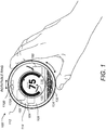
- FIG. 1 illustrates a perspective view of a thermostat 100, according to one embodiment.
- the thermostat 100 can be controlled by at least two types of user input, the first being a rotation of the outer ring 112, and the second being an inward push on an outer cap 108 until an audible and/or tactile "click" occurs.
- these two types of user inputs may be referred to as "manipulating" the thermostat.
- manipulating the thermostat may also include pressing keys on a keypad, voice recognition commands, and/or any other type of input that can be used to change or adjust settings on the thermostat 100.
- the outer cap 108 can comprise an assembly that includes the outer ring 112, a cover 114, an electronic display 116, and a metallic portion 124.
- Each of these elements, or the combination of these elements may be referred to as a "housing" for the thermostat 100.
- each of these elements, or the combination of these elements may also form a user interface.
- the user interface may specifically include the electronic display 116.
- the user interface 116 may be said to operate in an active display mode.
- the active display mode may include providing a backlight for the electronic display 116.
- the active display mode may increase the intensity and/or light output of the electronic display 116 such that a user can easily see displayed settings of the thermostat 100, such as a current temperature, a setpoint temperature, an HVAC function, and/or the like.
- the active display mode may be contrasted with an inactive display mode (not shown).
- the inactive display mode can disable a backlight, reduce the amount of information displayed, lessen the intensity of the display, and/or altogether turn off the electronic display 116, depending on the embodiment.
- the active display mode and the inactive display mode of the electronic display 116 may also or instead be characterized by the relative power usage of each mode.
- the active display mode may generally require substantially more electrical power than the inactive display mode.
- different operating modes of the electronic display 116 may instead be characterized completely by their power usage.
- the different operating modes of the electronic display 116 may be referred to as a first mode and a second mode, where the user interface requires more power when operating in the first mode than when operating in the second mode.
- the electronic display 116 may comprise a dot-matrix layout (individually addressable) such that arbitrary shapes can be generated, rather than being a segmented layout. According to some embodiments, a combination of dot-matrix layout and segmented layout is employed. According to some embodiments, electronic display 116 may be a backlit color liquid crystal display (LCD). An example of information displayed on the electronic display 116 is illustrated in FIG. 1 , and includes central numerals 120 that are representative of a current setpoint temperature. According to some embodiments, metallic portion 124 can have a number of slot-like openings so as to facilitate the use of a sensors 130, such as a passive infrared motion sensor (PIR), mounted beneath the slot-like openings.
- PIR passive infrared motion sensor
- the thermostat 100 can include additional components, such as a processing system 160, display driver 164, and a wireless communications system 166.
- the processing system 160 can adapted or configured to cause the display driver 164 to cause the electronic display 116 to display information to the user.
- the processing system 160 can also be configured to receive user input via the rotatable ring 112.
- These additional components, including the processing system 160, can be enclosed within the housing, as displayed in FIG. 1 . These additional components are described in further detail herein below.
- the processing system 160 is capable of carrying out the governance of the thermostat's operation.
- processing system 160 can be further programmed and/or configured to maintain and update a thermodynamic model for the enclosure in which the HVAC system is installed.
- the wireless communications system 166 can be used to communicate with devices such as personal computers, remote servers, handheld devices, smart phones, and/or other thermostats or HVAC system components. These communications can be peer-to-peer communications, communications through one or more servers located on a private network, or and/or communications through a cloud-based service.
- occupancy information can be a used in generating an effective and efficient scheduled program.
- an active proximity sensor 170A can be provided to detect an approaching user by infrared light reflection
- an ambient light sensor 170B can be provided to sense visible light.
- the proximity sensor 170A can be used in conjunction with a plurality of other sensors to detect proximity in the range of about one meter so that the thermostat 100 can initiate "waking up" when the user is approaching the thermostat and prior to the user touching the thermostat.
- proximity sensing is useful for enhancing the user experience by being “ready” for interaction as soon as, or very soon after the user is ready to interact with the thermostat. Further, the wake-up-on-proximity functionality also allows for energy savings within the thermostat by “sleeping" when no user interaction is taking place or about to take place.
- sensors that may be used, as well as the operation of the "wake up” function are described in much greater detail throughout the remainder of this disclosure.
- the thermostat can be physically and/or functionally divided into at least two different units. Throughout this disclosure, these two units can be referred to as a head unit and a backplate.
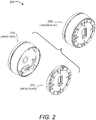
- FIG. 2 illustrates an exploded perspective view 200 of a thermostat 208 having a head unit 210 and a backplate 212, according to one embodiment. Physically, this arrangement may be advantageous during an installation process.
- the backplate 212 can first be attached to a wall, and the HVAC wires can be attached to a plurality of HVAC connectors on the backplate 212.
- the head unit 210 can be connected to the backplate 212 in order to complete the installation of the thermostat 208.
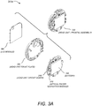
- FIG. 3A illustrates an exploded perspective view 300a of a head unit 330 with respect to its primary components, according to one embodiment.
- the head unit 330 may include an electronic display 360.
- the electronic display 360 may comprise an LCD module.
- the head unit 330 may include a mounting assembly 350 used to secure the primary components in a completely assembled head unit 330.
- the head unit 330 may further include a circuit board 340 that can be used to integrate various electronic components described further below.
- the circuit board 340 of the head unit 330 can include a manipulation sensor 342 to detect user manipulations of the thermostat.
- the manipulation sensor 342 may comprise an optical finger navigation module as illustrated in FIG. 3A .
- a rechargeable battery 344 may also be included in the assembly of the head unit 330.
- rechargeable battery 344 can be a Lithium-Ion battery, which may have a nominal voltage of 3.7 volts and a nominal capacity of 560 mAh.
- FIG. 3B illustrates an exploded perspective view 300b of a backplate 332 with respect to its primary components, according to one embodiment.
- the backplate 332 may include a frame 310 that can be used to mount, protect, or house a backplate circuit board 320.
- the backplate circuit board 320 may be used to mount electronic components, including one or more processing functions, and/or one or more HVAC wire connectors 322.
- the one or more HVAC wire connectors 322 may include integrated wire insertion sensing circuitry configured to determine whether or not a wire is mechanically and/or electrically connected to each of the one or more HVAC wire connectors 322.
- two relatively large capacitors 324 are a part of power stealing circuitry that can be mounted to the backplate circuit board 320. The power stealing circuitry is discussed further herein below.
- FIG. 4A illustrates a simplified functional block diagram 400a for a head unit, according to one embodiment.
- the functions embodied by block diagram 400a are largely self-explanatory, and may be implemented using one or more processing functions.
- the term "processing function" may refer to any combination of hardware and/or software.
- a processing function may include a microprocessor, a microcontroller, distributed processors, a lookup table, digital logic, logical/arithmetic functions implemented in analog circuitry, and/or the like.
- a processing function may also be referred to as a processing system, a processing circuit, or simply a circuit.
- a processing function on the head unit may be implemented by an ARM processor.
- the head unit processing function may interface with the electronic display 402, an audio system 404, and a manipulation sensor 406 as a part of a user interface 408.
- the head unit processing function may also facilitate wireless communications 410 by interfacing with various wireless modules, such as a Wi-Fi module 412 and/or a ZigBee module 414.
- the head unit processing function may be configured to control the core thermostat operations 416, such as operating the HVAC system.
- the head unit processing function may further be configured to determine or sense occupancy 418 of a physical location, and to determine building characteristics 420 that can be used to determine time-to-temperature characteristics.
- the processing function on the head unit may also be configured to learn and manage operational schedules 422, such as diurnal heat and cooling schedules.
- a power management module 462 may be used to interface with a corresponding power management module on the back plate, the rechargeable battery, and a power control circuit 464 on the back plate.
- the head unit processing function may include and/or be communicatively coupled to one or more memories.
- the one or more memories may include one or more sets of instructions that cause the processing function to operate as described above.
- the one or more memories may also include a sensor history and global state objects 424.
- the one or more memories may be integrated with the processing function, such as a flash memory or RAM memory available on many commercial microprocessors.
- the head unit processing function may also be configured to interface with a cloud management system 426, and may also operate to conserve energy wherever appropriate 428.
- An interface 432 to a backplate processing function 430 may also be included, and may be implemented using a hardware connector.
- FIG. 4B illustrates a simplified functional block diagram for a backplate, according to one embodiment.
- the backplate processing function can communicate with the head unit processing function 438.
- the backplate processing function can include wire insertion sensing 440 that is coupled to external circuitry 442 configured to provide signals based on different wire connection states.
- the backplate processing function may be configured to manage the HVAC switch actuation 444 by driving power FET circuitry 446 to control the HVAC system.
- the backplate processing function may also include a sensor polling interface 448 to interface with a plurality of sensors.
- the plurality of sensors may include a temperature sensor, a humidity sensor, a PIR sensor, a proximity sensor, an ambient light sensor, and or other sensors not specifically listed. This list is not meant to be exhaustive. Other types of sensors may be used depending on the particular embodiment and application, such as sound sensors, flame sensors, smoke detectors, and/or the like.
- the sensor polling interface 448 may be communicatively coupled to a sensor reading memory 450.
- the sensor reading memory 450 can store sensor readings and may be located internally or externally to a microcontroller or microprocessor.
- the backplate processing function can include a power management unit 460 that is used to control various digital and/or analog components integrated with the backplate and used to manage the power system of the thermostat.
- the power management system of this particular embodiment can include a bootstrap regulator 462, a power stealing circuit 464, a buck converter 466, and/or a battery controller 468.
- FIG. 5 illustrates a simplified circuit diagram 500 of a system for managing the power consumed by a thermostat, according to one embodiment.
- the powering circuitry 510 comprises a full-wave bridge rectifier 520, a storage and waveform-smoothing bridge output capacitor 522 (which can be, for example, on the order of 30 microfarads), a buck regulator circuit 524, a power-and-battery (PAB) regulation circuit 528, and a rechargeable lithium-ion battery 530.
- the powering circuitry 510 can be configured and adapted to have the characteristics and functionality described herein below. Description of further details of the powering circuitry 510 and associated components can be found elsewhere in the instant disclosure and/or in the commonly assigned U.S. 13/034,678 , supra, and U.S. 13/267,871 , supra.
- the powering circuitry 510 when there is a "C" wire presented upon installation, the powering circuitry 510 operates as a relatively high-powered, rechargeable-battery-assisted AC-to-DC converting power supply. When there is not a "C” wire presented, the powering circuitry 510 operates as a power-stealing, rechargeable-battery-assisted AC-to-DC converting power supply.
- the powering circuitry 510 generally serves to provide the voltage Vcc MAIN that is used by the various electrical components of the thermostat, which in one embodiment can be about 4.0 volts.
- the powering circuitry 510 may also be configured to "steal" power from one of the other HVAC wires in the absence of a "C” wire.
- active power stealing refers to the power stealing that is performed during periods in which there is no active call in place based on the lead from which power is being stolen.
- active power stealing refers to the power stealing that is performed when there is no active cooling call in place.
- active power stealing refers to the power stealing that is performed during periods in which there is an active call in place based on the lead from which power is being stolen.
- active power stealing refers to the power stealing that is performed when there is an active cooling call in place.
- power can be stolen from a selected one of the available call relay wires. While a complete description of the power stealing circuitry 510 can be found in the commonly assigned applications that have been previously incorporated herein by reference, the following brief explanation is sufficient for purposes of this disclosure.
- Some components in the thermostat may consume more instantaneous power than can be provided by power stealing alone.
- the power supplied by power stealing can be supplemented with the rechargeable battery 530.
- the thermostat when the thermostat is engaged in operations, such as when the electronic display is in an active display mode, power may be supplied by both power stealing and the rechargeable battery 530.
- some embodiments optimize the amount of time that the head unit processing function and the electronic display are operating in an active mode. In other words, it may be advantageous in some embodiments to keep the head unit processing function in a sleep mode or low power mode and to keep the electronic display in an inactive display mode as long as possible without affecting the user experience.
- the backplate processing function 508 can be configured to monitor the environmental sensors in a low-power mode, and then wake the head unit processing function 532 (AM3703) when needed to control the HVAC system, etc.
- the backplate processing function 508 can be used to monitor sensors used to detect the closeness of a user, and wake the head unit processing system 532 and/or the electronic display when it is determined that a user intends to interface with the thermostat.
- thermostat embodiments depicted and described in relation to FIGS. 1-5 are merely exemplary and not meant to be limiting. Many other hardware and/or software configurations may be used to implement a thermostat and the various functions described herein below. These embodiments should be seen as an exemplary platform in which the following embodiments can be implemented to provide an enabling disclosure. Of course, the following methods, systems, and/or software program products could also be implemented using different types of thermostats, different hardware, and/or different software.
- devices can be used to control various aspects of the homes environment, including air temperature, humidity, fan speed, music, television, appliances, and/or the like.
- Many embodiments of the present invention enable these devices to be configured to operate in one mode when the home is occupied and to operate in a second mode when the home is unoccupied.
- devices can be configured to activate user interfaces, maintain certain levels of temperature and/or humidity, provide predetermined volume levels, and detect user movements for recording and determining user profiles.
- devices can be configured to turn off user interfaces, conserve power by altering normal levels of temperature and humidity, turn off appliances, and otherwise reduce the power usage of the home when no one is there.
- embodiments described herein provide methods and systems designed to enable an away-state feature that automatically changes the operating mode of a control device when it is determined that an enclosure in which the control device is installed is no longer occupied.
- occupancy sensors may include any sensor configured to determine whether an enclosure is physically occupied.
- an occupancy sensor may include a Passive Infrared sensor (PIR).
- PIR Passive Infrared sensor
- an occupancy sensor may include a sensor configured to emit electromagnetic radiation and to receive reflections of electromagnetic radiation.
- an occupancy sensor may include a near-range PIR.
- Other examples of occupancy sensors may include microphones, CCD cameras, magnetic switches, microwave systems, and/or the like.
- An enclosure occupancy state can be continuously and automatically sensed using the occupancy sensors, the currently sensed state being classified as occupied (or "home” or “activity sensed”) or unoccupied (or “away” or “inactive”). If the currently sensed occupancy state has been "inactive" for a predetermined minimum interval, termed herein an away-state confidence window (ASCW), then an away-state mode of operation can be triggered in which an actual operating setpoint is changed to a predetermined energy saving away-state value, regardless of a setpoint value indicated by the normal control settings and/or schedule.
- the purpose of the away-state mode of operation is to avoid unnecessarily using energy when there are no occupants present to actually experience or enjoy the comfort of the enclosure.
- the away-state value may comprise a temperature, and may be set, by way of example, to a default predetermined value of 62 degrees for winter periods (or outside temperatures that would call for heating) and 84 degrees for summer periods (or outside temperatures that would call for cooling). Specific details of the away-state feature can also be found in U.S. Provisional Application No. 61/627,996 filed October 21, 2011 .
- the away-state confidence window corresponds to a time interval of sensed nonoccupancy after which a reasonably reliable operating assumption can be made, with a reasonable degree of statistical accuracy, that there are indeed no occupants in the enclosure.
- a predetermined period in the range of 90-180 minutes can be a suitable period for the ASCW to accommodate for common situations such as quiet book reading, working in the yard, short naps, etc. in which there is no sensed movement or related indication for the occupancy sensors to detect.
- the effectiveness of the away-state feature may in part depend upon how reliably the control unit can determine whether or not the enclosure is occupied. In one sense, this reliability may depend in part on the reliability of the occupancy sensors to detect a physical presence within a responsive area of the occupancy sensors. In another sense, this reliability may also depend in part on where the control unit has been placed in the enclosure, as well as the living patterns of the inhabitants. For example, a control unit may be placed in an area of an enclosure where is not easy for the occupancy sensors to detect whether someone is in the home or not, such as in a closet, a rarely-used hallway, a basement, or even in a high-traffic location that is obscured by other household objects.
- control unit itself to determine whether it is located in one of these non-ideal areas of an enclosure. It may also be difficult rely on deliberate user inputs (i.e. user-entered location information) to make this determination, as users may enter this data incorrectly if at all.
- a control unit may make a determination as to a level of "sensor confidence" before it relies on the occupancy sensors to enable the away-state feature.
- some embodiments herein may not enable the away-state feature upon installation. Instead, these embodiments may evaluate sensor responses during a trial period in order to establish a level of sensor confidence. If the level of sensor confidence is sufficient, and exceeds a predetermined threshold, the away-state feature can be enabled. Otherwise, to avoid creating an uncomfortable environment within an occupied enclosure, the away-state feature can remain disabled until such a level of sensor confidence is established.
- sensor confidence can be established by monitoring the readings from one or more occupancy sensors, and determining whether they have detected a threshold level of occupancy events. Simply, if the occupancy sensors detect a physical presence within their responsive areas during a large portion of the operating time, it can be assumed that the control unit is disposed at a location within the enclosure that can reliably detect whether the enclosure is occupied or not. In this case, a high level of sensor confidence can be assumed, such that the occupancy sensors can be relied upon to determine when the away-state feature should be activated.
- the occupancy sensors only detect a physical presence within their responsive areas during a relatively small portion of the operating time, it can be assumed that the control unit is disposed at a location within the enclosure that cannot reliably detect whether the enclosure is occupied or not. In this case, only a low level of sensor confidence can be assumed, and thus the occupancy sensors may not necessarily be relied upon to determine when the away-state feature should be activated. In one embodiment, the away-state feature will not be enabled unless a requisite level of sensor confidence is established.
- the away-state feature can be used to determine when a home is unoccupied, and in response, to activate an automated setpoint temperature setback mode where a predetermined setpoint temperature is set on the thermostat. For example, for an unoccupied home in the summertime, the setpoint temperature may be higher than the setpoint temperature would otherwise be in an occupied home. Likewise, for an unoccupied home in the wintertime, the setpoint temperature may be lower than the setpoint temperature would otherwise be in an occupied home. It will be understood that various permutations of these conditions may apply depending on the climate and user preferences.
- the thermostat determines whether it can, or cannot, reliably go into an away-state mode to save energy, i.e., whether it has "sensor confidence" for its occupancy sensor measurements.
- the away-state feature is disabled for a predetermined period such as 7 days after device startup (i.e., initial installation or factory reset).
- the occupancy sensor activity can be tracked by discrete sequential "time buckets" of activity, such as 5-minute buckets, where a bucket is either empty (if no occupancy event is sensed in that interval) or full (if one or more occupancy events is sensed in that interval).
- the predetermined threshold can be empirically determined for a particular model, version, or setting of the thermostat. In one example, it has been found that 3.5% is a suitable threshold, i.e., if there are 30 or more full buckets for the three-day sample, then “sensor confidence" is established, although this will vary for different devices, models, and settings.
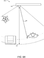
- FIG. 6A illustrates an overhead view 600a of an area monitored by a thermostat 602, according to one embodiment.
- the area monitored by the thermostat 602 may comprise a room within a building, a hallway, an open living area, and/or the like.
- the temperature sensors of thermostat 602 may be configured to detect the ambient temperature of the area being monitored.
- various sensors of the thermostat 602 may have different responsive areas.
- an occupancy sensor may include a responsive area 604 denoted by the set of dashed lines.
- the term "responsive area" may include an area in which a phenomenon that a sensor is configured to detect will generate a response by the sensor.
- a motion detector associated with responsive area 604 could detect motion within the responsive area 604 of an object meeting the specifications of the motion detector. It should be noted that some objects may not meet the specifications of the motion detector, such as stationary objects, objects that do not emit a sufficient level of infrared radiation, or smaller objects such as pets.
- Merely generating a response from a sensor may not be sufficient to infer that a physical presence is detected.
- the actual response generated by a sensor when an event occurs within its associated responsive area will in many cases be dependent on the intensity of the event or the distance of the event from the thermostat. For example, if an event occurs along the periphery of the associated responsive area, the response of the sensor may be small. However, if an event occurs closer to the thermostat, the response of the sensor may be larger. Therefore, some embodiments may determine a threshold for a sensor response in order to qualify as a physical presence.
- a threshold can correspond to a voltage/current output, a digital readout, the frequency, or other similar electrical output of a sensor.
- the threshold may correspond to a certain distance, such as distance 608 for an event having a known intensity. For example, a user approaching the thermostat 602 with a PIR sensor associated with responsive area 604 could trip a threshold when coming within distance 608 of the thermostat 602. Larger persons or persons moving rapidly may trip the threshold nearer or farther than distance 608 at the same threshold. It should be noted, that in one embodiment, no threshold need be used, and any activity registered by the occupancy sensor may be sufficient to infer a physical presence.
- FIG. 6A shows an example of a thermostat 602 that is installed in a location where a high level of sensor confidence may be established. This may correspond to a living room, a kitchen, or a busy hallway.
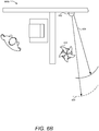
- FIG. 6B illustrates an overhead view 600b of another area monitored by thermostat.
- the thermostat 602 is installed in a location that may not see enough user traffic to establish a high level of user confidence.
- the responsive area 604 of the occupancy sensor may be targeted in a direction that will not capture the physical presence of occupants of the home very often.
- obstacles, such as a plant 610 may it secure the view of the thermostat 602.
- the thermostat 602 may be installed in an enclosure inside the home, such as a closet or nook. Any or all of these factors may reduce the level of sensor confidence such that the away-state feature should not be enabled.
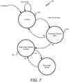
- FIG. 7 illustrates a state diagram 700 for determining whether sufficient sensor confidence can be established for enabling and away-state feature, according to one embodiment.
- a trial period can be used to train the thermostat.
- occupancy sensor readings may be recorded and evaluated.
- the occupancy sensor readings can be analyzed to determine whether a threshold criterion has been met, and if so, the away-state feature can be enabled.
- the operations in state diagram 700 begin when the thermostat is installed, reset, or otherwise caused to default to a set of factory settings. At this point, the thermostat may enter into a training state 702. The thermostat may stay in the training state 702 throughout the trial period. While in the training state 702, the thermostat may record any and all measurements provided by one or more occupancy sensors. In one embodiment, the occupancy sensor measurements can be time stamped and/or recorded based on a portion of the trial period in which they occurred.
- the thermostat may enter an evaluation state 704 where it can be determined whether a threshold criterion has been met.
- the thermostat can use the comparison to the threshold criterion to establish whether sufficiently true indications of occupancy conditions were sensed by the occupancy sensors during the trial period.
- the thermostat can analyze all of the occupancy sensor responses that were recorded during the trial period, and can then determine whether there were enough occupancy sensor responses to characterize the responses as true indications of occupancy.
- too few occupancy sensor responses may indicate that the thermostat is not truly sensing the occupancy of the enclosure because it may be assumed that if placed in a better location the thermostat would receive more occupancy sensor responses.
- sufficient occupancy sensor responses may be characterized as a true indication that the thermostat can correctly determine the occupancy of the enclosure.
- the thermostat can move into an enabled state 706 where the away-state feature is enabled. Afterwards, when the thermostat detects that the enclosure is no longer occupied, the thermostat may enter into and away-state mode of operation 708. This determination may be made by a processing system based on readings acquired by the occupancy sensors, and the away-state mode of operation may include an automated setback temperature setback mode. In one embodiment, the away-state feature may be enabled throughout the remaining service period of the thermostat, or until it is installed in a new location, reset, or loses power.
- thermostat can disable the away-state feature. For example, after the away-state feature is enabled, the thermostat can return to the training state 702 if long periods of non-occupancy are detected. After the trial period ends again, the thermostat could again determine whether the threshold criterion is met and whether the away-state feature should be disabled or continue to be enabled. In some embodiments, the training period may be re-entered and repeated in perpetuity throughout the life of the thermostat.
- the trial period may be repeated only a few times after installation.
- users may interact with thermostat more than usual in the weeks following installation in order to make sure that it is working properly, or to fine tune the user-adjustable features. Therefore, occupancy sensor readings during the weeks immediately following installation may not be truly indicative of the real level of sensor confidence throughout the lifetime of the thermostat.
- the trial period may be repeated one or more times after installation. For example, the trial period may be repeated one, two, three, four, five or, six times, and so forth, depending upon the embodiment in particular installation characteristics.
- the thermostat may return to the training state 702 and repeat the trial period.
- the trial period can be repeated by clearing a memory storing the occupancy sensor readings and starting over.
- the trial period may be considered a sliding window, wherein the oldest sensor readings may be removed and replaced by newer sensor readings as they are obtained. For example, an entire day's worth of the oldest sensor readings could be removed and replaced by the current day's sensor readings.
- the length of the trial period may also be adjusted in this embodiment such that one week's worth of sensor measurements are evaluated at the end of each day after a least one week of sensor measurements are obtained.
- the trial period lasting one week is merely exemplary, and the trial period may also last one day, ten days, one month, two weeks, and so forth. If at the end of any successful trial period the threshold criterion is determined to be met, the thermostat can transition into the enabled state 706 and the away-state feature may be enabled.
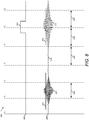
- FIG. 8 illustrates a graph 800 of various sensors responses during a trial period, according to one embodiment.
- graph 800 illustrates how a trial period may be divided into a plurality of time windows, or "time buckets.” Instead of storing an indication every time an occupancy sensor detects a physical presence, a single indication of whether a physical presence was detected can be stored for each time window. This may simplify calculations, reduce the amount of memory required, and/or make it easier to correlate sensor measurements with other events.
- the timeline in FIG. 8 illustrates at least a portion of a trial period. This portion of the trial period can be divided up into various time windows, such as windows 824, 826, 828, and 830.
- each of the time windows is approximately 5 minutes long.
- each of the time windows can be between 3 and 7 minutes, approximately 10 minutes, 1 minute, and so forth.
- each of the time windows may have a uniform length, while in other embodiments each of the time windows may have different lengths.
- FIG. 8 also illustrates a number of sensor responses.
- Response 806 may correspond to an occupancy sensor, such as a PIR sensor or an active proximity sensor.
- Response 806 illustrates a number of distinct response types that correspond to whether or not a physical presence is detected within the sensor's responsive area.
- Section 817 of response 806 illustrates a response characteristic of a physical presence detected within the responsive area of the occupancy sensor.
- section 822 illustrates another response characteristic of a physical presence having a somewhat longer duration than the response of section 817.
- Section 816 of response 806 illustrates a response characteristic of an occupancy sensor that does not detect a physical presence within its responsive area.
- Occupancy sensor responses indicative of a physical presence may be confined to a single time window or may span several time windows.
- a threshold may be used, such as threshold 834 to determine whether a sensor response is sufficient to indicate a physical presence.
- any time window recording a sensor response that satisfies the threshold may be recorded in the time window during which occupancy was sensed.
- section 817 would record an occupancy response during time window 824.
- Section 822 would record an occupancy response during both time window 828 and time window 830.
- thermostats may include so-called "learning thermostats" that learn user behaviors such that actual interactions or minimized after an initial period of acclamation. Therefore, occupancy may need to be detected during conditions where users rarely interact with the thermostat.
- the trial period for determining whether the away-state feature can be enabled takes place shortly after installation, many of the physical presence events sensed by the occupancy sensors may correspond to interactions with the thermostat before it learns user behavior, and thus may not be truly indicative of the level of sensor confidence needed to correctly determine occupancy.
- one embodiment may use various interaction sensors to determine when a user interacts with the thermostat.
- the responses of these interaction sensors can be correlated with the responses of the occupancy sensors in order to eliminate the occupancy sensor responses that coincide with interactions.
- Interaction sensors may include near-range PIR sensors, near-range active proximity sensors, sound sensors, light sensors, and/or the like.
- an interaction sensor includes sensors configured to detect a physical manipulation of a user interface of the thermostat. These sensors may be referred to herein as "manipulation sensors.”
- response 802 may represent the output of a manipulation sensor, such as an optical sensor coupled to a rotatable ring disposed around an outer perimeter of the thermostat housing.
- the optical sensor may provide an output whenever a rotation of the outer ring takes place, or when the user otherwise manipulates the user interface.
- response 802 includes section 820 representing a physical manipulation of the thermostat. Note that section 820 of response 802 coincides with section 822 of response 806 from the occupancy sensor. Therefore, section 822 of response 806 can be excluded by some embodiments from the readings recorded during the trial period. In contrast, there is no corresponding manipulation event for section 817 of response 806, and thus time window 820 may record a record physical presence event.
- manipulation events may not precisely coincide with physical presence events as detected by these two types of sensors.
- physical presence events may be disregarded that occurred within the same time window.
- physical presence events may be disregarded that occurred within one, two, or three time windows of the manipulation event.
- the recorded sensor responses can be analyzed.
- the sensor response for each time window may be stored within a data structure.
- Generating a metric characterizing the occupancy during the time period may comprise determining the percentage of time windows during which at least one physical presence was detected compared to the number of time windows during which no physical presence was detected. From this, a percentage of occupancy may be obtained. This metric may be referred to as an "occupancy level" and may represent the percentage of time windows during which physical presences were detected.
- Some embodiments may also store metrics that differentiate between weekends and weekdays. Some embodiments may also store metrics that represents physical presence events detected during the same time window during each day.
- FIG. 9 illustrates a graph 900 depicting one method of storing occupancy sensor measurements, according to one embodiment.
- response 902 response 906, as well as sections 916, 920, and 922 are similar to those shown in FIG. 8 .
- Response 908 can represent how the various responses are stored in a data structure within a memory.
- time windows 924, 926, 928, and 930 may represent time windows that occur daily.
- time window 924 may represent 9:00 AM through 9:05 AM during each weekday.
- the value stored in the memory location for time window 924 can be adjusted.
- the value stored in the memory location for each time window represents the percentage of days during the time period that a physical presence event was detected during the time window.
- the value 910 stored for time window 924 can represent 100% if response 906 occurs in the first day of the trial period. Notice also that values 912 and 914 represent 0% because section 922 of response 906 corresponds with a manipulation event.
- FIG. 10 illustrates a graph 1000 depicting storage of occupancy sensor measurements during the trial period, according to one embodiment.
- Trace 1002 represents the value stored for each time window during the previous days of the trial period. In this example, a physical presence event occurred during time window 1026 during every previous day during the trial period. Similarly, a physical presence event occurred during time window 1030 during a proximally 50% of the previous days during the trial period.
- Trace 1004 represents sensor responses during a current day of the trial period. In this example, a physical presence event was detected during time windows 1014, 1016, and 1018. Note that other physical presence events may have occurred during other time windows, such as time window 1032; however these physical presence events may have been excluded because of other sensor responses, such as responses from manipulation sensors.
- Trace 1006 represents the value stored for each time window after the current day's physical presence events have been recorded.
- trace 1006 is the result of applying trace 1004 to trace 1002.
- the value stored for time window 1026 remains at 100%.
- physical presence event 1016 was detected on the current day, and thus the value stored for time window 1028 changes from 0% to 33%. It can be inferred from this calculation that the values represented by trace 1002 represent the cumulative effects of two previous days. Therefore value 1022 of 33% represents two previous days without physical presence events combined with the physical presence event of the current day.
- physical presence event 1018 can be added to the 50% value previously stored for time window 1030 to generate a new value of 66%.
- Time window 1032 does not show a physical presence event on the current day or on any previous days. Therefore, the value for time window 1032 remains at 0%.
- each time window may represent a bucket of time that reoccurs throughout the trial period. Although 24 hours has been used as the reoccurrence period, it will be clear in light of this disclosure that any other period could also be used. Some embodiments may store measurements according to every hour, or according to every 12 hour cycle. Other embodiments may store measurements that repeat weekly.
- the thermostat may again enter the training mode and begin a new trial period.
- the memory locations for each time window may be reset to zero.
- the values currently stored in the memory locations for each time window may be retained, and the percentage may continue to be adjusted over the new trial period.
- Other embodiments may discount the value of previously stored in the memory locations such that it is weighed less than new values acquired during the new trial period.
- the value stored for each time window represents sensor measurements obtained during time intervals that repeat daily
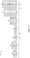
- FIG. 11 illustrates a representation of occupancy levels for each day in one week, according to one embodiment.
- occupancy levels 1106, 1108, 1110, 1112, 1114, 1116, and 1118 have been generated for each day by combining the occupancy levels for each time window occurring for that day. This may be done by simply adding the time intervals during a day in which a physical presence was detected and comparing it to the number of time intervals during the day in which no physical presence was detected.
- the occupancy levels for each day can be combined.
- a total weekday occupancy level 1102 can be generated by combining the occupancy levels from each weekday.
- a total weekend occupancy level 1104 can be generated by combining the occupancy levels from Saturday and Sunday.
- the weekday occupancy level 1102 can be combined with the weekend occupancy level 1104 by combining the two statistics proportionally.
- the weekday occupancy level 1102 can be multiplied by 5/7 and the weekend occupancy level 1104 can be multiplied by 2/7 and added together to generate a final occupancy level.
- a single data structure may be used for a single set of time windows during weekdays, and a single data structure may be used for a single set of time windows during weekends.
- These the weekday time windows can be combined to generate a weekday occupancy level
- the weekend time windows can be combined to generate a weekend occupancy level.
- the weekend occupancy level can be combined with the weekday occupancy level as described above to generate a final occupancy level.
- different time windows can be combined using different weights.
- a morning occupancy level can be generated and combined with an evening occupancy level.
- a mealtime occupancy level can be generated and combined with a non-mealtime occupancy level.
- These different time windows can be combined using different weights. For example, a mealtime occupancy level may be weighted more heavily than a non-mealtime occupancy level when combined. It will be understood in light of this disclosure that many other types of combinations and repeating sequences of time windows may be used.
- FIG. 12 illustrates a flowchart 1200 of a method for determining whether an away-state feature should be enabled, according to one embodiment.
- the method may include installing or resetting the thermostat (1201). A reset may be manually initiated by a user, or may be remotely instructed by a control server.
- the method may also include recording sensor readings (1202).
- the sensor readings may be from occupancy sensor(s) that are disposed within the housing of the thermostat and configured to detect physical presences of users within a responsive area of the occupancy sensor(s).
- the occupancy sensor may be in operative communication with a processing system.
- the occupancy sensor(s) may comprise a PIR sensor.
- a processing system may be disposed within the housing and coupled to a user interface.
- the processing system may be configured to be in operative communication with one or more temperature sensors for determining an ambient air temperature, and in operative communication with one or more input devices including the user interface for determining a setpoint temperature value, and in still further operative communication with a heating, ventilation, and air conditioning (HVAC) system to control the HVAC system based at least in part on a comparison of a measured ambient temperature and the setpoint temperature value.
- HVAC heating, ventilation, and air conditioning
- the sensor readings may be acquired during a trial period.
- the trial period begins upon installation and/or reset of the thermostat.
- the trial period may be in any interval of time, including between five and eight days, as well as one week.
- the acquired sensor readings may, in one embodiment, be stored according to a plurality of time windows.
- the trial period may be divided into the plurality of time windows, wherein each of the readings from the occupancy sensors are stored in a corresponding one of the plurality of time windows during which the reading occurs.
- sensor readings may be excluded that also correspond with manipulation or an inferred intent to interact with or view the thermostat.
- the method may also include determining the end of the trial period (1204). At the end of the trial period, an occupancy level may be computed for the trial period based on the stored sensor readings, or the stored indications of how often the occupancy sensor(s) detected physical presences of users during the trial period. In one embodiment, stored indications that correspond to a weekday can be treated differently when computing the occupancy level than a subset of the stored indications that corresponds to a weekend.
- the processing system may comprise a head unit processor and a backplate processor as described above.
- the backplate processor may receive, store, and manage the occupancy sensor(s) readings.
- the readings may be sent to the head unit processor at the end of the trial period in order to generate an occupancy level and to determine whether the occupancy level satisfies the threshold criterion.
- the backplate processor may perform all of these functions without waking the head unit processor.
- the method may additionally include determining whether a threshold criterion is satisfied (1206).
- the thermostat enters into an away-state mode of operation upon a determination by the processing system based upon readings acquired by the occupancy sensor(s) that an away-stay criterion indicative of a non-occupancy condition for an enclosure in which the thermostat has been installed has been satisfied.
- the away-mode of operation may include an automated setpoint temperature setback mode.
- the threshold criterion may be designed to establish whether the thermostat is placed in a location in the enclosure where occupancy information is readily sensed by the occupancy sensor(s) of the thermostat. In one embodiment, the threshold criterion represents an occupancy level of between approximately 0.02 and 0.10. In another embodiment, the threshold criterion represents an occupancy level of approximately 0.035.
- Determining whether the threshold criterion is satisfied may include comparing the occupancy level for the trial period to the threshold criterion. In another embodiment, this determination may comprise comparing information derived from the trial period readings to the threshold criterion to establish whether sufficiently true indications of occupancy conditions were sensed by the occupancy sensor(s) during the trial period.
- the method may further include enabling the away-state feature of the thermostat if it is determined that the sufficiently true indications of occupancy conditions were sensed during the trial period (1208).
- the processing system can be further configured to determine whether to activate the away-state feature after a second trial period.
- the second trial period may be instituted in response to a failure to satisfy the threshold criterion.
- the second trial period may be instituted after a determination that the sufficiently true indications of occupancy conditions were not sensed during the first trial period. If is determined that the away-state feature should not be enabled, then method may again begin recording new occupancy sensor readings during a new trial period (1210).
- the trial period may be divided into repeating time windows and stored in memory locations that are later combined according to various methods disclosed herein to compute an occupancy level.
- Other similar features may be incorporated into the method above.
- FIG. 12 provides particular methods of determining whether an away-state feature should be enabled according to various embodiments of the present invention. Other sequences of steps may also be performed according to alternative embodiments. For example, alternative embodiments of the present invention may perform the steps outlined above in a different order. Moreover, the individual steps illustrated in FIG. 12 may include multiple sub-steps that may be performed in various sequences as appropriate to the individual step. Furthermore, additional steps may be added or removed depending on the particular applications. One of ordinary skill in the art would recognize many variations, modifications, and alternatives.
- a device which in some particularly advantageous embodiments is a thermostat
- its related user interfaces and related methods and systems that facilitate a user-friendly, enjoyable, pleasant experience during the crucial "first contact” period and equally crucial first couple of days and/or weeks thereafter in that (a) the user is not bothered with the need to decide whether to allow (activate) or to not allow (not activate) the automatic away-state functionality when they are setting up the device, while at the same time (b) the device will not trigger into the automatic away-state unless it determines itself to be "qualified” to make that decision, thereby avoiding (or substantially lessening the likelihood) of a case in which the device triggers into the auto-away state (e.g., turning down the setpoint temperature during wintertime) while the user is actually still occupying the premises.
- the auto-away state e.g., turning down the setpoint temperature during wintertime
Landscapes
- Engineering & Computer Science (AREA)
- Chemical & Material Sciences (AREA)
- Combustion & Propulsion (AREA)
- Mechanical Engineering (AREA)
- General Engineering & Computer Science (AREA)
- Human Computer Interaction (AREA)
- Signal Processing (AREA)
- Physics & Mathematics (AREA)
- Fuzzy Systems (AREA)
- Mathematical Physics (AREA)
- General Physics & Mathematics (AREA)
- Automation & Control Theory (AREA)
- Air Conditioning Control Device (AREA)
- Selective Calling Equipment (AREA)
Claims (15)
- Steuereinheit (100; 208; 602) zur Steuerung des Betriebs von zumindest einem Smart-Home-System, umfassend:zumindest ein Gehäuse;zumindest ein Verarbeitungssystem (160), das innerhalb des zumindest einen Gehäuses angeordnet ist, wobei das zumindest eine Verarbeitungssystem so konfiguriert ist, dass es in operativer Kommunikation mit einer Benutzerschnittstelle (408) ist; undzumindest einen Anwesenheitssensor in operativer Kommunikation mit dem zumindest einen Verarbeitungssystem;wobei das zumindest eine Verarbeitungssystem ferner konfiguriert ist, automatisch zu ermitteln, ob eine Abwesenheitszustandsfunktion für das Gebäude, in dem das Smart-Home-System installiert ist, aktiviert werden soll, dadurch gekennzeichnet, dass das zumindest eine Verarbeitungssystem konfiguriert ist, die Ermittlung durchzuführen durch:Empfangen von Messwerten von dem zumindest einen Anwesenheitssensor während eines Versuchszeitraums;Vergleichen von Informationen, die aus den Messwerten abgeleitet wurden, mit zumindest einem Schwellenwertkriterium, um festzustellen, ob hinreichend deutliche Hinweise auf Anwesenheitsbedingungen von dem zumindest einen Anwesenheitssensor während des Versuchszeitraums erfasst wurden; undAktivieren der Abwesenheitszustandsfunktion der Steuereinheit nur dann, wenn ermittelt wird, dass die hinreichend deutlichen Hinweise auf Anwesenheitsbedingungen während des Versuchszeitraums erfasst wurden.
- Steuereinheit nach Anspruch 1, wobei die Abwesenheitszustandsfunktion die Steuereinheit veranlasst, in einen Abwesenheitszustands-Betriebsmodus einzutreten, wenn das zumindest eine Verarbeitungssystem basierend auf den von dem zumindest einen Anwesenheitssensor erfassten Messwerten ermittelt, dass ein Abwesenheitszustandskriterium, das eine Nicht-Anwesenheitsbedingung für das Gebäude, in dem die Steuereinheit installiert wurde, angibt, erfüllt wurde.
- Steuereinheit nach Anspruch 2, wobei das zumindest eine Verarbeitungssystem so konfiguriert ist, dass es sich zum Ermitteln einer Umgebungslufttemperatur in operativer Kommunikation mit einem oder mehreren Temperatursensoren befindet, zum Ermitteln eines Temperatursollwerts in operativer Kommunikation mit einem oder mehreren Eingabegeräten, die die Benutzerschnittstelle beinhalten, befindet, und weiterhin in operativer Kommunikation mit einem Heizungs-, Lüftungs- und Klimatisierungssystem (HLK-System) befindet, um das HLK-System zumindest teilweise basierend auf einem Vergleich von einer gemessenen Umgebungstemperatur und dem Temperatursollwert zu steuern.
- Steuereinheit nach Anspruch 1, wobei der zumindest eine Anwesenheitssensor einen passiven Infrarotsensor (PIR-Sensor) umfasst.
- Steuereinheit nach Anspruch 1, wobei das Schwellenwertkriterium verwendet wird, um festzustellen, ob die Steuereinheit an einem Standort in dem Gebäude platziert ist, an dem Anwesenheitsinformationen leicht von dem zumindest einen Anwesenheitssensor der Steuereinheit erfasst werden können.
- Steuereinheit nach Anspruch 1, wobei das definierte Zeitintervall automatisch mit der Installation der Steuereinheit innerhalb des Gebäudes beginnt.
- Steuereinheit nach Anspruch 1, wobei der Versuchszeitraum etwa zwischen 5 und 8 Tage umfasst.
- Verfahren zum Befähigen einer Steuereinheit (100; 208 ; 602) für ein Smart-Home-System, eine Abwesenheitszustandsfunktion zu aktivieren, das Verfahren umfassend:Empfangen von Messwerten von zumindest einem Anwesenheitssensor während eines definierten Versuchszeitraums, wobei die Steuereinheit Folgendes umfasst:zumindest ein Gehäuse;zumindest ein Verarbeitungssystem (160), das innerhalb des zumindest einen Gehäuses angeordnet und so konfiguriert ist, dass es in operativer Kommunikation mit einer Benutzerschnittstelle (408) ist; undwobei der zumindest eine Anwesenheitssensor in operativer Kommunikation mit dem zumindest einen Verarbeitungssystem steht, dadurch gekennzeichnet, dass das Verfahren ferner die folgenden Schritte umfasst:Vergleichen, unter Nutzung des zumindest einen Verarbeitungssystems der Steuereinheit, von Informationen, die aus den Messwerten abgeleitet wurden, mit zumindest einem Schwellenwertkriterium, um zu ermitteln, ob von dem zumindest einen Anwesenheitssensor während des Versuchszeitraums hinreichend deutliche Hinweise auf Anwesenheitsbedingungen erfasst wurden; undAktivieren, unter Nutzung des zumindest einen Verarbeitungssystems der Steuereinheit, einer Abwesenheitszustandsfunktion der Steuereinheit, wenn ermittelt wird, dass die hinreichend deutlichen Hinweise auf Anwesenheitsbedingungen während des Versuchszeitraums erfasst wurden.
- Verfahren nach Anspruch 8, wobei die Abwesenheitszustandsfunktion die Steuereinheit veranlasst, in einen Abwesenheitszustands-Betriebsmodus einzutreten, wenn das zumindest eine Verarbeitungssystem basierend auf den von dem zumindest einen Anwesenheitssensor erfassten Messwerten ermittelt, dass ein Abwesenheitskriterium, das eine Nicht-Anwesenheitsbedingung für das Gebäude, in dem die Steuereinheit installiert wurde, angibt, erfüllt wurde.
- Verfahren nach Anspruch 9, wobei das zumindest eine Verarbeitungssystem so konfiguriert ist, dass es sich zum Ermitteln einer Umgebungslufttemperatur in operativer Kommunikation mit einem oder mehreren Temperatursensoren befindet, zum Ermitteln eines Temperatursollwerts in operativer Kommunikation mit einem oder mehreren Eingabegeräten, die die Benutzerschnittstelle beinhalten, befindet, und weiterhin in operativer Kommunikation mit einem Heizungs-, Lüftungs- und Klimatisierungssystem (HLK-System) befindet, um das HLK-System zumindest teilweise basierend auf einem Vergleich von einer gemessenen Umgebungstemperatur und dem Temperatursollwert zu steuern.
- Verfahren nach Anspruch 8, wobei der zumindest eine Anwesenheitssensor einen passiven Infrarotsensor (PIR-Sensor) umfasst.
- Verfahren nach Anspruch 8, wobei das Schwellenwertkriterium verwendet wird, um festzustellen, ob die Steuereinheit an einem Standort in dem Gebäude platziert ist, an dem Anwesenheitsinformationen leicht von dem zumindest einen Anwesenheitssensor der Steuereinheit erfasst werden können.
- Verfahren nach Anspruch 8, wobei der Versuchszeitraum automatisch mit der Installation der Steuereinheit innerhalb des Gebäudes beginnt.
- Verfahren nach Anspruch 8, wobei der Versuchszeitraum etwa zwischen 5 und 8 Tage umfasst.
- Verfahren nach Anspruch 8, ferner umfassend das Empfangen einer Eingabe über die Benutzerschnittstelle, um die Abwesenheitszustandsfunktion zu deaktivieren, nachdem das Verarbeitungssystem die Abwesenheitszustandsfunktion der Steuereinheit zuvor aktiviert hat.
Applications Claiming Priority (5)
| Application Number | Priority Date | Filing Date | Title |
|---|---|---|---|
| US201161627996P | 2011-10-21 | 2011-10-21 | |
| US201161550345P | 2011-10-21 | 2011-10-21 | |
| US13/279,151 US8950686B2 (en) | 2010-11-19 | 2011-10-21 | Control unit with automatic setback capability |
| PCT/US2012/058206 WO2013058968A1 (en) | 2011-10-21 | 2012-09-30 | Smart-home device that self-qualifies for away-state functionality |
| EP12841861.3A EP2769277B1 (de) | 2011-10-21 | 2012-09-30 | Smart-home-gerät mit selbstqualifizierung für funktion im abwesenheitszustand |
Related Parent Applications (1)
| Application Number | Title | Priority Date | Filing Date |
|---|---|---|---|
| EP12841861.3A Division EP2769277B1 (de) | 2011-10-21 | 2012-09-30 | Smart-home-gerät mit selbstqualifizierung für funktion im abwesenheitszustand |
Publications (2)
| Publication Number | Publication Date |
|---|---|
| EP3112972A1 EP3112972A1 (de) | 2017-01-04 |
| EP3112972B1 true EP3112972B1 (de) | 2021-05-26 |
Family
ID=57201791
Family Applications (1)
| Application Number | Title | Priority Date | Filing Date |
|---|---|---|---|
| EP16174943.7A Active EP3112972B1 (de) | 2011-10-21 | 2012-09-30 | Smart-home-vorrichtung mit selbstqualifizierung für abwesenheitsfunktion |
Country Status (2)
| Country | Link |
|---|---|
| EP (1) | EP3112972B1 (de) |
| CN (1) | CN106054958B (de) |
Families Citing this family (1)
| Publication number | Priority date | Publication date | Assignee | Title |
|---|---|---|---|---|
| CN111399392B (zh) * | 2020-04-02 | 2022-02-01 | 深圳创维-Rgb电子有限公司 | 基于智慧屏的智能家居交互控制方法、装置和智慧屏 |
Family Cites Families (9)
| Publication number | Priority date | Publication date | Assignee | Title |
|---|---|---|---|---|
| US5986357A (en) * | 1997-02-04 | 1999-11-16 | Mytech Corporation | Occupancy sensor and method of operating same |
| CA2202008C (en) * | 1997-04-07 | 2000-02-08 | Hugues Demilleville | Energy management system |
| EP1489719A3 (de) * | 2003-06-20 | 2007-05-02 | Matsushita Electric Industrial Co., Ltd. | Energievewaltungssystem, Energieverwaltungsverfahren und Einheit zur Verfügungsstellung von Informationen über energiesparende empfohlene Einrichtung |
| US7918406B2 (en) | 2008-07-22 | 2011-04-05 | Howard Rosen | Override of nonoccupancy status in a thermostat device based upon analysis of recent patterns of occupancy |
| US8199010B2 (en) * | 2009-02-13 | 2012-06-12 | Lutron Electronics Co., Inc. | Method and apparatus for configuring a wireless sensor |
| US9049756B2 (en) * | 2009-04-09 | 2015-06-02 | Koninklijke Philips N.V. | Intelligent lighting control system and network comprising multiple-channel photo sensor |
| US20110006887A1 (en) * | 2009-07-13 | 2011-01-13 | Kmc Controls, Inc. | Programmable Communicating Thermostat And System |
| US8510255B2 (en) | 2010-09-14 | 2013-08-13 | Nest Labs, Inc. | Occupancy pattern detection, estimation and prediction |
| US9104211B2 (en) | 2010-11-19 | 2015-08-11 | Google Inc. | Temperature controller with model-based time to target calculation and display |
-
2012
- 2012-09-30 CN CN201610515219.4A patent/CN106054958B/zh active Active
- 2012-09-30 EP EP16174943.7A patent/EP3112972B1/de active Active
Non-Patent Citations (1)
| Title |
|---|
| None * |
Also Published As
| Publication number | Publication date |
|---|---|
| EP3112972A1 (de) | 2017-01-04 |
| CN106054958A (zh) | 2016-10-26 |
| CN106054958B (zh) | 2019-07-12 |
Similar Documents
| Publication | Publication Date | Title |
|---|---|---|
| US10274914B2 (en) | Smart-home device that self-qualifies for away-state functionality | |
| EP2769277B1 (de) | Smart-home-gerät mit selbstqualifizierung für funktion im abwesenheitszustand | |
| US8532827B2 (en) | Prospective determination of processor wake-up conditions in energy buffered HVAC control unit | |
| CA2885868C (en) | Radiant heating controls and methods for an environmental control system | |
| US8630742B1 (en) | Preconditioning controls and methods for an environmental control system | |
| US10012407B2 (en) | Heating controls and methods for an environmental control system | |
| CA2885867C (en) | Preconditioning controls and methods for an environmental control system | |
| CN103229119A (zh) | 具有自动回调能力的控制单元 | |
| EP3112972B1 (de) | Smart-home-vorrichtung mit selbstqualifizierung für abwesenheitsfunktion |
Legal Events
| Date | Code | Title | Description |
|---|---|---|---|
| PUAI | Public reference made under article 153(3) epc to a published international application that has entered the european phase |
Free format text: ORIGINAL CODE: 0009012 |
|
| STAA | Information on the status of an ep patent application or granted ep patent |
Free format text: STATUS: THE APPLICATION HAS BEEN PUBLISHED |
|
| AC | Divisional application: reference to earlier application |
Ref document number: 2769277 Country of ref document: EP Kind code of ref document: P |
|
| AK | Designated contracting states |
Kind code of ref document: A1 Designated state(s): AL AT BE BG CH CY CZ DE DK EE ES FI FR GB GR HR HU IE IS IT LI LT LU LV MC MK MT NL NO PL PT RO RS SE SI SK SM TR |
|
| STAA | Information on the status of an ep patent application or granted ep patent |
Free format text: STATUS: REQUEST FOR EXAMINATION WAS MADE |
|
| 17P | Request for examination filed |
Effective date: 20170619 |
|
| RBV | Designated contracting states (corrected) |
Designated state(s): AL AT BE BG CH CY CZ DE DK EE ES FI FR GB GR HR HU IE IS IT LI LT LU LV MC MK MT NL NO PL PT RO RS SE SI SK SM TR |
|
| RIN1 | Information on inventor provided before grant (corrected) |
Inventor name: FISHER, EVAN J. Inventor name: MATSUOKA, YOKY |
|
| RAP1 | Party data changed (applicant data changed or rights of an application transferred) |
Owner name: GOOGLE LLC |
|
| STAA | Information on the status of an ep patent application or granted ep patent |
Free format text: STATUS: EXAMINATION IS IN PROGRESS |
|
| 17Q | First examination report despatched |
Effective date: 20180131 |
|
| GRAP | Despatch of communication of intention to grant a patent |
Free format text: ORIGINAL CODE: EPIDOSNIGR1 |
|
| STAA | Information on the status of an ep patent application or granted ep patent |
Free format text: STATUS: GRANT OF PATENT IS INTENDED |
|
| RIC1 | Information provided on ipc code assigned before grant |
Ipc: F24F 11/30 20180101ALI20201123BHEP Ipc: G05D 23/19 20060101AFI20201123BHEP |
|
| RIN1 | Information on inventor provided before grant (corrected) |
Inventor name: FISHER, EVAN J. Inventor name: MATSUOKA, YOKY |
|
| INTG | Intention to grant announced |
Effective date: 20201214 |
|
| GRAS | Grant fee paid |
Free format text: ORIGINAL CODE: EPIDOSNIGR3 |
|
| GRAA | (expected) grant |
Free format text: ORIGINAL CODE: 0009210 |
|
| STAA | Information on the status of an ep patent application or granted ep patent |
Free format text: STATUS: THE PATENT HAS BEEN GRANTED |
|
| AC | Divisional application: reference to earlier application |
Ref document number: 2769277 Country of ref document: EP Kind code of ref document: P |
|
| AK | Designated contracting states |
Kind code of ref document: B1 Designated state(s): AL AT BE BG CH CY CZ DE DK EE ES FI FR GB GR HR HU IE IS IT LI LT LU LV MC MK MT NL NO PL PT RO RS SE SI SK SM TR |
|
| REG | Reference to a national code |
Ref country code: GB Ref legal event code: FG4D |
|
| REG | Reference to a national code |
Ref country code: CH Ref legal event code: EP |
|
| REG | Reference to a national code |
Ref country code: DE Ref legal event code: R096 Ref document number: 602012075710 Country of ref document: DE |
|
| REG | Reference to a national code |
Ref country code: AT Ref legal event code: REF Ref document number: 1396860 Country of ref document: AT Kind code of ref document: T Effective date: 20210615 |
|
| REG | Reference to a national code |
Ref country code: IE Ref legal event code: FG4D |
|
| REG | Reference to a national code |
Ref country code: NL Ref legal event code: FP |
|
| REG | Reference to a national code |
Ref country code: LT Ref legal event code: MG9D |
|
| REG | Reference to a national code |
Ref country code: AT Ref legal event code: MK05 Ref document number: 1396860 Country of ref document: AT Kind code of ref document: T Effective date: 20210526 |
|
| PG25 | Lapsed in a contracting state [announced via postgrant information from national office to epo] |
Ref country code: HR Free format text: LAPSE BECAUSE OF FAILURE TO SUBMIT A TRANSLATION OF THE DESCRIPTION OR TO PAY THE FEE WITHIN THE PRESCRIBED TIME-LIMIT Effective date: 20210526 Ref country code: BG Free format text: LAPSE BECAUSE OF FAILURE TO SUBMIT A TRANSLATION OF THE DESCRIPTION OR TO PAY THE FEE WITHIN THE PRESCRIBED TIME-LIMIT Effective date: 20210826 Ref country code: AT Free format text: LAPSE BECAUSE OF FAILURE TO SUBMIT A TRANSLATION OF THE DESCRIPTION OR TO PAY THE FEE WITHIN THE PRESCRIBED TIME-LIMIT Effective date: 20210526 Ref country code: FI Free format text: LAPSE BECAUSE OF FAILURE TO SUBMIT A TRANSLATION OF THE DESCRIPTION OR TO PAY THE FEE WITHIN THE PRESCRIBED TIME-LIMIT Effective date: 20210526 Ref country code: LT Free format text: LAPSE BECAUSE OF FAILURE TO SUBMIT A TRANSLATION OF THE DESCRIPTION OR TO PAY THE FEE WITHIN THE PRESCRIBED TIME-LIMIT Effective date: 20210526 |
|
| PG25 | Lapsed in a contracting state [announced via postgrant information from national office to epo] |
Ref country code: SE Free format text: LAPSE BECAUSE OF FAILURE TO SUBMIT A TRANSLATION OF THE DESCRIPTION OR TO PAY THE FEE WITHIN THE PRESCRIBED TIME-LIMIT Effective date: 20210526 Ref country code: RS Free format text: LAPSE BECAUSE OF FAILURE TO SUBMIT A TRANSLATION OF THE DESCRIPTION OR TO PAY THE FEE WITHIN THE PRESCRIBED TIME-LIMIT Effective date: 20210526 Ref country code: PL Free format text: LAPSE BECAUSE OF FAILURE TO SUBMIT A TRANSLATION OF THE DESCRIPTION OR TO PAY THE FEE WITHIN THE PRESCRIBED TIME-LIMIT Effective date: 20210526 Ref country code: NO Free format text: LAPSE BECAUSE OF FAILURE TO SUBMIT A TRANSLATION OF THE DESCRIPTION OR TO PAY THE FEE WITHIN THE PRESCRIBED TIME-LIMIT Effective date: 20210826 Ref country code: PT Free format text: LAPSE BECAUSE OF FAILURE TO SUBMIT A TRANSLATION OF THE DESCRIPTION OR TO PAY THE FEE WITHIN THE PRESCRIBED TIME-LIMIT Effective date: 20210927 Ref country code: LV Free format text: LAPSE BECAUSE OF FAILURE TO SUBMIT A TRANSLATION OF THE DESCRIPTION OR TO PAY THE FEE WITHIN THE PRESCRIBED TIME-LIMIT Effective date: 20210526 Ref country code: IS Free format text: LAPSE BECAUSE OF FAILURE TO SUBMIT A TRANSLATION OF THE DESCRIPTION OR TO PAY THE FEE WITHIN THE PRESCRIBED TIME-LIMIT Effective date: 20210926 Ref country code: GR Free format text: LAPSE BECAUSE OF FAILURE TO SUBMIT A TRANSLATION OF THE DESCRIPTION OR TO PAY THE FEE WITHIN THE PRESCRIBED TIME-LIMIT Effective date: 20210827 |
|
| PG25 | Lapsed in a contracting state [announced via postgrant information from national office to epo] |
Ref country code: ES Free format text: LAPSE BECAUSE OF FAILURE TO SUBMIT A TRANSLATION OF THE DESCRIPTION OR TO PAY THE FEE WITHIN THE PRESCRIBED TIME-LIMIT Effective date: 20210526 Ref country code: RO Free format text: LAPSE BECAUSE OF FAILURE TO SUBMIT A TRANSLATION OF THE DESCRIPTION OR TO PAY THE FEE WITHIN THE PRESCRIBED TIME-LIMIT Effective date: 20210526 Ref country code: SM Free format text: LAPSE BECAUSE OF FAILURE TO SUBMIT A TRANSLATION OF THE DESCRIPTION OR TO PAY THE FEE WITHIN THE PRESCRIBED TIME-LIMIT Effective date: 20210526 Ref country code: SK Free format text: LAPSE BECAUSE OF FAILURE TO SUBMIT A TRANSLATION OF THE DESCRIPTION OR TO PAY THE FEE WITHIN THE PRESCRIBED TIME-LIMIT Effective date: 20210526 Ref country code: CZ Free format text: LAPSE BECAUSE OF FAILURE TO SUBMIT A TRANSLATION OF THE DESCRIPTION OR TO PAY THE FEE WITHIN THE PRESCRIBED TIME-LIMIT Effective date: 20210526 Ref country code: DK Free format text: LAPSE BECAUSE OF FAILURE TO SUBMIT A TRANSLATION OF THE DESCRIPTION OR TO PAY THE FEE WITHIN THE PRESCRIBED TIME-LIMIT Effective date: 20210526 Ref country code: EE Free format text: LAPSE BECAUSE OF FAILURE TO SUBMIT A TRANSLATION OF THE DESCRIPTION OR TO PAY THE FEE WITHIN THE PRESCRIBED TIME-LIMIT Effective date: 20210526 |
|
| REG | Reference to a national code |
Ref country code: DE Ref legal event code: R097 Ref document number: 602012075710 Country of ref document: DE |
|
| PLBE | No opposition filed within time limit |
Free format text: ORIGINAL CODE: 0009261 |
|
| STAA | Information on the status of an ep patent application or granted ep patent |
Free format text: STATUS: NO OPPOSITION FILED WITHIN TIME LIMIT |
|
| REG | Reference to a national code |
Ref country code: CH Ref legal event code: PL |
|
| 26N | No opposition filed |
Effective date: 20220301 |
|
| REG | Reference to a national code |
Ref country code: BE Ref legal event code: MM Effective date: 20210930 |
|
| PG25 | Lapsed in a contracting state [announced via postgrant information from national office to epo] |
Ref country code: IS Free format text: LAPSE BECAUSE OF FAILURE TO SUBMIT A TRANSLATION OF THE DESCRIPTION OR TO PAY THE FEE WITHIN THE PRESCRIBED TIME-LIMIT Effective date: 20210926 Ref country code: MC Free format text: LAPSE BECAUSE OF FAILURE TO SUBMIT A TRANSLATION OF THE DESCRIPTION OR TO PAY THE FEE WITHIN THE PRESCRIBED TIME-LIMIT Effective date: 20210526 Ref country code: AL Free format text: LAPSE BECAUSE OF FAILURE TO SUBMIT A TRANSLATION OF THE DESCRIPTION OR TO PAY THE FEE WITHIN THE PRESCRIBED TIME-LIMIT Effective date: 20210526 |
|
| PG25 | Lapsed in a contracting state [announced via postgrant information from national office to epo] |
Ref country code: LU Free format text: LAPSE BECAUSE OF NON-PAYMENT OF DUE FEES Effective date: 20210930 Ref country code: IT Free format text: LAPSE BECAUSE OF FAILURE TO SUBMIT A TRANSLATION OF THE DESCRIPTION OR TO PAY THE FEE WITHIN THE PRESCRIBED TIME-LIMIT Effective date: 20210526 Ref country code: BE Free format text: LAPSE BECAUSE OF NON-PAYMENT OF DUE FEES Effective date: 20210930 Ref country code: IE Free format text: LAPSE BECAUSE OF NON-PAYMENT OF DUE FEES Effective date: 20210930 |
|
| PG25 | Lapsed in a contracting state [announced via postgrant information from national office to epo] |
Ref country code: LI Free format text: LAPSE BECAUSE OF NON-PAYMENT OF DUE FEES Effective date: 20210930 Ref country code: CH Free format text: LAPSE BECAUSE OF NON-PAYMENT OF DUE FEES Effective date: 20210930 |
|
| PG25 | Lapsed in a contracting state [announced via postgrant information from national office to epo] |
Ref country code: HU Free format text: LAPSE BECAUSE OF FAILURE TO SUBMIT A TRANSLATION OF THE DESCRIPTION OR TO PAY THE FEE WITHIN THE PRESCRIBED TIME-LIMIT; INVALID AB INITIO Effective date: 20120930 Ref country code: CY Free format text: LAPSE BECAUSE OF FAILURE TO SUBMIT A TRANSLATION OF THE DESCRIPTION OR TO PAY THE FEE WITHIN THE PRESCRIBED TIME-LIMIT Effective date: 20210526 |
|
| P01 | Opt-out of the competence of the unified patent court (upc) registered |
Effective date: 20230506 |
|
| PG25 | Lapsed in a contracting state [announced via postgrant information from national office to epo] |
Ref country code: MK Free format text: LAPSE BECAUSE OF FAILURE TO SUBMIT A TRANSLATION OF THE DESCRIPTION OR TO PAY THE FEE WITHIN THE PRESCRIBED TIME-LIMIT Effective date: 20210526 |
|
| PG25 | Lapsed in a contracting state [announced via postgrant information from national office to epo] |
Ref country code: TR Free format text: LAPSE BECAUSE OF FAILURE TO SUBMIT A TRANSLATION OF THE DESCRIPTION OR TO PAY THE FEE WITHIN THE PRESCRIBED TIME-LIMIT Effective date: 20210526 |
|
| PG25 | Lapsed in a contracting state [announced via postgrant information from national office to epo] |
Ref country code: MT Free format text: LAPSE BECAUSE OF FAILURE TO SUBMIT A TRANSLATION OF THE DESCRIPTION OR TO PAY THE FEE WITHIN THE PRESCRIBED TIME-LIMIT Effective date: 20210526 |
|
| PGFP | Annual fee paid to national office [announced via postgrant information from national office to epo] |
Ref country code: DE Payment date: 20250929 Year of fee payment: 14 |
|
| PGFP | Annual fee paid to national office [announced via postgrant information from national office to epo] |
Ref country code: NL Payment date: 20250926 Year of fee payment: 14 |
|
| PGFP | Annual fee paid to national office [announced via postgrant information from national office to epo] |
Ref country code: GB Payment date: 20250929 Year of fee payment: 14 |
|
| PGFP | Annual fee paid to national office [announced via postgrant information from national office to epo] |
Ref country code: FR Payment date: 20250925 Year of fee payment: 14 |