EP3112968A1 - Autonomous platform car - Google Patents
Autonomous platform car Download PDFInfo
- Publication number
- EP3112968A1 EP3112968A1 EP15754460.2A EP15754460A EP3112968A1 EP 3112968 A1 EP3112968 A1 EP 3112968A1 EP 15754460 A EP15754460 A EP 15754460A EP 3112968 A1 EP3112968 A1 EP 3112968A1
- Authority
- EP
- European Patent Office
- Prior art keywords
- travel
- travel route
- speed
- traveling
- unit
- Prior art date
- Legal status (The legal status is an assumption and is not a legal conclusion. Google has not performed a legal analysis and makes no representation as to the accuracy of the status listed.)
- Granted
Links
Images









Classifications
-
- G—PHYSICS
- G05—CONTROLLING; REGULATING
- G05D—SYSTEMS FOR CONTROLLING OR REGULATING NON-ELECTRIC VARIABLES
- G05D1/00—Control of position, course, altitude or attitude of land, water, air or space vehicles, e.g. using automatic pilots
- G05D1/02—Control of position or course in two dimensions
- G05D1/021—Control of position or course in two dimensions specially adapted to land vehicles
- G05D1/0268—Control of position or course in two dimensions specially adapted to land vehicles using internal positioning means
- G05D1/0274—Control of position or course in two dimensions specially adapted to land vehicles using internal positioning means using mapping information stored in a memory device
-
- G—PHYSICS
- G05—CONTROLLING; REGULATING
- G05D—SYSTEMS FOR CONTROLLING OR REGULATING NON-ELECTRIC VARIABLES
- G05D1/00—Control of position, course, altitude or attitude of land, water, air or space vehicles, e.g. using automatic pilots
- G05D1/0011—Control of position, course, altitude or attitude of land, water, air or space vehicles, e.g. using automatic pilots associated with a remote control arrangement
- G05D1/0016—Control of position, course, altitude or attitude of land, water, air or space vehicles, e.g. using automatic pilots associated with a remote control arrangement characterised by the operator's input device
-
- G—PHYSICS
- G05—CONTROLLING; REGULATING
- G05D—SYSTEMS FOR CONTROLLING OR REGULATING NON-ELECTRIC VARIABLES
- G05D1/00—Control of position, course, altitude or attitude of land, water, air or space vehicles, e.g. using automatic pilots
- G05D1/0088—Control of position, course, altitude or attitude of land, water, air or space vehicles, e.g. using automatic pilots characterized by the autonomous decision making process, e.g. artificial intelligence, predefined behaviours
-
- G—PHYSICS
- G05—CONTROLLING; REGULATING
- G05D—SYSTEMS FOR CONTROLLING OR REGULATING NON-ELECTRIC VARIABLES
- G05D1/00—Control of position, course, altitude or attitude of land, water, air or space vehicles, e.g. using automatic pilots
- G05D1/02—Control of position or course in two dimensions
- G05D1/021—Control of position or course in two dimensions specially adapted to land vehicles
- G05D1/0212—Control of position or course in two dimensions specially adapted to land vehicles with means for defining a desired trajectory
- G05D1/0221—Control of position or course in two dimensions specially adapted to land vehicles with means for defining a desired trajectory involving a learning process
-
- G—PHYSICS
- G05—CONTROLLING; REGULATING
- G05D—SYSTEMS FOR CONTROLLING OR REGULATING NON-ELECTRIC VARIABLES
- G05D1/00—Control of position, course, altitude or attitude of land, water, air or space vehicles, e.g. using automatic pilots
- G05D1/02—Control of position or course in two dimensions
- G05D1/021—Control of position or course in two dimensions specially adapted to land vehicles
- G05D1/0212—Control of position or course in two dimensions specially adapted to land vehicles with means for defining a desired trajectory
- G05D1/0223—Control of position or course in two dimensions specially adapted to land vehicles with means for defining a desired trajectory involving speed control of the vehicle
-
- G—PHYSICS
- G05—CONTROLLING; REGULATING
- G05D—SYSTEMS FOR CONTROLLING OR REGULATING NON-ELECTRIC VARIABLES
- G05D1/00—Control of position, course, altitude or attitude of land, water, air or space vehicles, e.g. using automatic pilots
- G05D1/02—Control of position or course in two dimensions
- G05D1/021—Control of position or course in two dimensions specially adapted to land vehicles
- G05D1/0231—Control of position or course in two dimensions specially adapted to land vehicles using optical position detecting means
- G05D1/0238—Control of position or course in two dimensions specially adapted to land vehicles using optical position detecting means using obstacle or wall sensors
- G05D1/024—Control of position or course in two dimensions specially adapted to land vehicles using optical position detecting means using obstacle or wall sensors in combination with a laser
Definitions
- the present invention relates to an autonomous travel vehicle that autonomously travels while reproducing a specified travel route.
- Patent Citation 1 discloses a cleaning robot.
- the cleaning robot includes a casing equipped with the following means: travel drive means for traveling on a floor surface, position detection means for detecting a position of the casing on the floor surface, cleaning means for cleaning the floor surface, operation receiving means for receiving operation inputs for the travel drive means and the cleaning means, storage means for storing a travel route based on positions detected by the position detection means in association with received content of the operation receiving means, and control means for reading stored content stored in the storage means so as to control the travel drive means and the cleaning means based on the stored content.
- Patent Citation 2 discloses a plurality of moving bodies that move in a file. Each of the moving bodies is taught about track data chronologically indicating time points and positions of the moving body at the time points, and the time points and the positions at the time points are stored. In this way, the moving body can move such that the moving body exists at a position indicated in the track data at a time point indicated in the track data.
- An autonomous travel vehicle includes a platform portion, a traveling unit, a storage unit, an arrival position prediction unit, a corrected speed calculation unit, and a reproduction travel command calculation unit.
- the traveling unit controls the platform portion to travel in accordance with a travel control command.
- the storage unit stores travel route data.
- the travel route data includes a plurality of subgoal points set on a planned travel route, associated arrival times at which the autonomous travel vehicle reaches each of the plurality of subgoal points, and associated traveling speeds of the platform portion, respectively, at the plurality of subgoal points.
- the arrival position prediction unit predicts a predicted arrival position of the platform portion based on the traveling speed and the arrival time when the reproduction travel mode is executed.
- the reproduction travel mode is a travel mode in which the autonomous travel vehicle autonomously travels along the travel route based on the travel route data.
- the corrected speed calculation unit calculates the corrected traveling speed based on a predicted traveling distance and a required traveling distance, when the reproduction travel mode is executed.
- the predicted traveling distance is a distance between a current position of the platform portion and the predicted arrival position.
- the required traveling distance is a traveling distance necessary to reach an arrival target subgoal point.
- the arrival target subgoal point is a subgoal point corresponding to a target point to be reached by the platform portion.
- the corrected traveling speed is a corrected speed of the traveling speed.
- the reproduction travel command calculation unit calculates a reproduction travel control command based on the corrected traveling speed as the travel control command, when the reproduction travel mode is executed.
- the arrival position prediction unit first predicts the predicted arrival position.
- the corrected speed calculation unit calculates the predicted traveling distance from the predicted arrival position and the current position.
- the corrected speed calculation unit calculates the required traveling distance necessary to reach the arrival target subgoal point.
- the corrected speed calculation unit calculates the corrected traveling speed based on the predicted traveling distance and the required traveling distance.
- the reproduction travel command calculation unit calculates the reproduction travel control command based on the corrected traveling speed, so as to set the reproduction travel control command as the travel control command.
- the traveling unit controls the platform portion to travel based on the travel control command calculated based on the corrected traveling speed (the reproduction travel control command).
- the travel route data includes not only the plurality of subgoal points set on the travel route but also the associated arrival times when the subgoal points are respectively reached and the associated traveling speeds respectively at the subgoal points. In this way, the autonomous travel vehicle can reproduce and travel the travel route while reproducing operations having a concept of time.
- the (arrival) traveling speed stored in the travel route data is corrected based on the predicted traveling distance and the required traveling distance, when the reproduction travel mode is executed. In this way, even if the travel route data has an error due to a measurement error, the error of the travel route data can be corrected in accordance with the actual traveling. As a result, the autonomous travel vehicle can travel while assuredly reproducing the travel route.
- the required traveling distance may be a distance between the current position and the arrival target subgoal point.
- the deviation can be reduced before reaching the next target point (the arrival target subgoal point).
- the autonomous travel vehicle may further include an elapsed autonomous travel time counting unit.
- the elapsed autonomous travel time counting unit counts elapsed autonomous travel time from a start of the reproduction travel mode.
- the required traveling distance may be a distance between a current subgoal point and the arrival target subgoal point.
- the current subgoal point is a subgoal point associated with an arrival time corresponding to the elapsed autonomous travel time.
- the autonomous travel vehicle can travel while assuredly reproducing the taught travel route.
- the traveling unit may be comprised of a pair of main wheels disposed to face each other on the left and right sides in the travel direction of the platform portion.
- the pair of main wheels may be capable of rotating independently of each other.
- each of a first traveling speed and a second traveling speed, being speeds of the pair of main wheels include a parallel speed component and a turning speed component.
- the parallel speed component is a speed that determines a center speed of the platform portion (the autonomous travel vehicle).
- the turning speed component is a speed that determines turning of the platform portion (the autonomous travel vehicle).
- the corrected speed calculation unit calculates a corrected parallel speed component and a corrected turning speed component as the corrected traveling speed.
- the corrected parallel speed component is a corrected speed of the parallel speed component.
- the corrected turning speed component is a corrected speed of the turning speed component.
- the corrected speed calculation unit may further calculate the corrected parallel speed component including a travel route correction speed component based on a travel route error.
- the travel route error indicates a deviation between the travel route and the platform portion.
- the travel route correction speed component is a correction speed to join the travel route.
- the autonomous travel vehicle can turn and join the travel route based on the travel route error.
- the autonomous travel vehicle can autonomously join the travel route.
- the travel route error may be a distance between a virtual travel route and the current position.
- the virtual travel route is a travel route expressed by a straight line connecting the current subgoal point and the arrival target subgoal point. In this way, the travel route correction speed component can be calculated by a simpler calculation.
- the arrival position prediction unit may further predict a straight arrival prediction point.
- the straight arrival prediction point is a position of the platform portion that is predicted to be reached by traveling straight from the current position.
- the travel route error may be a distance between the virtual travel route and the straight arrival prediction point. In this way, if the autonomous travel vehicle is at a position deviating from the travel route, the autonomous travel vehicle can join the travel route in a quicker manner.
- the corrected parallel speed component may be divided into a first parallel speed component and a second parallel speed component at a predetermined ratio.
- the travel route correction speed component may be calculated by using the second parallel speed component. In this way, the travel route correction speed component can be calculated without the first traveling speed and/or the second traveling speed being the maximum speed or higher or being the minimum speed or lower.
- a first travel route correction speed component may be calculated as the product of the second parallel speed component and a first constant.
- the first constant is determined by a function that monotonically increases within a range of 0 to 1 along with an increase of the travel route error.
- the first travel route correction speed component is the travel route correction speed component for the first traveling speed.
- the second travel route correction speed component may be calculated as the product of the second parallel speed component and a second constant.
- the second constant is determined by a difference between 1 and the first constant.
- the second travel route correction speed component is the travel route correction speed component for the second traveling speed.
- the autonomous travel vehicle is at a position deviating from the travel route, and if the autonomous travel vehicle autonomously joins the travel route, it is possible to determine the turning for joining the travel route based on the travel route error and on which side of the travel route the platform portion (the autonomous travel vehicle) exists.
- the travel route data may further store direction angles in association respectively with a plurality of subgoal points.
- the direction angle is an angle indicating a direction of the platform portion at each of the plurality of subgoal points.
- the arrival position prediction unit may further predict a predicted direction angle.
- the predicted direction angle is an angle indicating a direction at the predicted arrival position.
- the corrected speed calculation unit may calculate the corrected turning speed component based on a target direction angle change and a predicted direction angle change.
- the target direction angle change is an direction angle change necessary to turn to an arrival target direction angle.
- the arrival target direction angle is a direction angle associated with the arrival target subgoal point.
- the predicted direction angle change is a difference between the predicted direction angle and a current direction angle.
- the current direction angle is a direction angle indicating a direction of the platform portion at the current position.
- the travel route data may further store travel curvature radii in association respectively with the subgoal points.
- the travel curvature radius is a curvature radius for the platform portion (the autonomous travel vehicle) when it is to pass each of the subgoal points.
- the turning speed component may be calculated based on the traveling speed corresponding to the parallel speed component and the travel curvature radius.
- the autonomous travel vehicle may further include an elapsed teaching time counting unit, and a taught data generating unit.
- the elapsed teaching time counting unit counts an elapsed teaching time when a manual operation teaching mode is executed.
- the manual operation teaching mode is a travel mode in which the travel route is taught via an operation of an operator.
- the elapsed teaching time is a time from start of the manual operation teaching mode.
- the taught data generating unit When the manual operation teaching mode is executed, the taught data generating unit generates the travel route data.
- the travel route data includes the taught subgoal points and the associated elapsed teaching times when the taught subgoal points are obtained. In this way, the taught travel route by the operation of the operator can be stored in the travel route data so as to contain a concept of time.
- the autonomous travel vehicle can assuredly reproduce and travel the planned travel route even if the travel route data has an error.
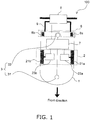
- Fig. 1 is a diagram illustrating an overall structure of the autonomous travel vehicle 100.
- the autonomous travel vehicle 100 of this embodiment illustrated in Fig. 1 is an autonomous travel vehicle in which an operation by an operator is taught to the autonomous travel vehicle 100, so that the autonomous travel vehicle 100 reproduces the operation taught by the operator (including a taught travel route and an operation having a concept of time).
- the autonomous travel vehicle 100 includes a platform portion 1, a traveling unit 2, a detection unit 3, an operation portion 5, and a control unit 7.
- the platform portion 1 constitutes a main body of the autonomous travel vehicle 100.
- the traveling unit 2 is provided to the platform portion 1.
- the traveling unit 2 travels in accordance with a travel control command (described later) so that the platform portion 1 travels.
- the detection unit 3 detects an obstacle (a traveling obstacle) and a wall and the like on the travel route, so as to output position information of an obstacle, a wall, and the like to the control unit 7.
- the operation portion 5 is fixed to the upper rear side of the platform portion 1 via an attachment member 9.
- the operation portion 5 is operated by an operator when the operator teaches a travel route by operating the autonomous travel vehicle 100 (when a manual operation teaching mode is executed).
- the operation using the operation portion 5 is output to the control unit 7, and as a result, when the manual operation teaching mode is executed, the autonomous travel vehicle 100 is controlled based on the operation of the operation portion 5 by the operator.
- various settings of the autonomous travel vehicle 100 can be made.
- the control unit 7 is electrically connected to motors 23a and 23b of the traveling unit 2 (described later), so as to supply a drive power to control the motors.
- the control unit 7 can input signals from the detection unit 3 and obtains the position information of an obstacle, a wall, and the like based on the signal.
- control unit 7 obtains a position of the autonomous travel vehicle 100 on a movement plane (a travel environment) based on the position information of an obstacle, a wall, and the like.
- control unit 7 may detect a traveling obstacle that is on the travel route or may (is predicted to) enter the travel route so as to hinder the traveling, based on the signal obtained from the detection unit 3.
- the detailed structures of the traveling unit 2, the detection unit 3, the operation portion 5, and the control unit 7 of the autonomous travel vehicle 100 will be described later.
- the autonomous travel vehicle 100 further includes an auxiliary wheel unit 8.
- the auxiliary wheel unit 8 includes two auxiliary wheels 8a and 8b.
- the two auxiliary wheels 8a and 8b are attached to the rear bottom part of the platform portion 1 in a manner capable of independently rotating. With the auxiliary wheel unit 8, the autonomous travel vehicle 100 can stably and smoothly travel.
- the traveling unit 2 of this embodiment illustrated in Fig. 1 is a traveling unit called an "opposed two-wheel differential type" traveling unit. Accordingly, the traveling unit 2 includes a pair of main wheels 21a and 21b and two motors 23a and 23b.
- the main wheels 21a and 21b are disposed on the bottom part substantially in the middle of the platform portion 1, so as to face each other on the left and right sides of the platform portion 1 in the travel direction.
- main wheels 21a and 21b are connected to output rotation shafts of the motors 23a and 23b, respectively, whose rotation speed can be controlled independently of each other by the control unit 7. Accordingly, the main wheels 21a and 21b can rotate at arbitrary rotation speed independently of each other.
- an electric motor such as a servo motor and/or a brushless motor can be used, for example, as the motors 23a and 23b.
- the traveling unit 2 can change (turn) the travel direction of the platform portion 1 (the autonomous travel vehicle 100) by differentiating between the rotation speed of the main wheel 21a and the rotation speed of the main wheel 21b.
- the platform portion 1 can travel straight.
- the detection unit 3 includes a front detector 31 and a rear detector 33.
- the front detector 31 detects an obstacle, a wall, and the like in front of the autonomous travel vehicle 100.
- the rear detector 33 detects an obstacle, a wall, and the like behind the autonomous travel vehicle 100.
- each of the front detector 31 and the rear detector 33 outputs a signal including information about a distance between the autonomous travel vehicle 100 and the obstacle, the wall, or the like and a direction of the obstacle, the wall, or the like viewed from the autonomous travel vehicle 100.
- the detection unit 3 can output relative position information of the obstacle, the wall, or the like viewed from the autonomous travel vehicle 100 to the control unit 7.
- a laser range finder (LRF) or the like having a detection range of at least 180 degrees and a detection distance of at least 4 meters can be used, for example, as the front detector 31 and the rear detector 33 of the detection unit 3.
- Fig. 2 is a diagram illustrating a structure of the operation portion 5.
- the operation portion 5 includes operation handles 51a and 51b, a setting unit 53, a display unit 55, an interface 57, and a casing 59.
- the operation handles 51a and 51b are attached respectively to the left and right of the casing 59 in a rotatable manner. Rotation amounts (operation amounts) and rotation directions of the operation handles 51 a and 51b are converted into electric signals by the interface 57 and are input to the control unit 7.
- the operation handle 51a is an input interface that instructs a traveling speed in the traveling direction
- the operation handle 51b is an input interface that instructs a steering angle.
- the setting unit 53 switches the travel mode of the autonomous travel vehicle 100 to either a reproduction travel mode or the manual operation teaching mode.
- the travel mode set by the setting unit 53 is output to a switching unit 77 of the control unit 7 ( Fig. 3 ) via the interface 57.
- the setting unit 53 may be capable of making other various settings of the autonomous travel vehicle 100.
- the setting unit 53 can be comprised of, for example, switches and/or a keyboard that make various settings of the travel mode and the like of the autonomous travel vehicle 100.
- the setting unit 53 may be comprised of a touch panel and may be formed integrally with the display unit 55.
- the display unit 55 reads and displays information such as various settings of the autonomous travel vehicle 100 from the control unit 7 via the interface 57.
- a display such as a liquid crystal display can be used.
- the setting unit 53 and the display unit 55 are integrally formed as described above, a display having a touch panel function can be used as the display unit 55 (and the setting unit 53).
- the interface 57 converts the rotation amounts and the rotation directions of the operation handles 51a and 51b, switch and/or key inputs of the setting unit 53, and the like into electric signals and outputs the electric signals to the control unit 7.
- the interface 57 reads information about the autonomous travel vehicle 100 from the control unit 7 in accordance with an operator's instruction or the like, and outputs the information to the display unit 55.
- a microcomputer board can be used as the interface 57.
- the microcomputer board includes, for example, a signal converter that converts the rotation amounts and the rotation directions of the operation handles 51a and 51b and a set state of the setting unit 53 into electric signals, a display unit driving circuitry that displays information on the display unit 55, and a communication interface for transmitting and receiving signals to and from the control unit 7.
- Fig. 3 is a diagram illustrating an overall structure of the control unit.
- control unit 7 can be realized using a microcomputer system or the like, which includes a central processing unit (CPU), a storage device comprised of a hard disk drive, a read only memory (ROM), a random access memory (RAM), a storage medium reading device, and the like, and an interface that performs signal conversions.
- CPU central processing unit
- storage device comprised of a hard disk drive
- ROM read only memory
- RAM random access memory
- storage medium reading device and the like
- interface that performs signal conversions.
- a portion or all of the functions of individual units of the control unit 7 described below may be realized in a program. Further, the program may be stored in the storage device of the microcomputer board. Alternatively, a part or a all of functions of individual units of the control unit 7 may be realized using a custom IC or the like.
- the control unit 7 includes a taught data generating unit 71, a position estimating unit 72, a storage unit 73, an elapsed time counting unit 74, a motor driving unit 75, an obstacle information obtaining unit 76, and the switching unit 77.
- the taught data generating unit 71 obtains information about positions every predetermined time, the positions that the autonomous travel vehicle 100 passes when the operator operates the autonomous travel vehicle 100 using the operation portion 5, when the manual operation teaching mode is executed. Then, the taught data generating unit 71 converts the information about positions into coordinate values on a coordinate system expressing the movement plane on which the autonomous travel vehicle 100 travels (hereinafter referred to as a movement coordinate system). Further, the taught data generating unit 71 stores, in the storage unit 73 (described later), the information about positions after the coordinate conversion and the elapsed teaching times when the information about positions are obtained, in association with each other.
- the information about positions described above indicates target points to be passed set on the planned travel route. Accordingly, the information about positions described above is referred to as "subgoal points”.
- the taught data generating unit 71 continues to obtain the subgoal point from a travel start position of the autonomous travel vehicle 100 until the operator stops the autonomous travel vehicle 100 (until the end of the manual operation teaching mode or until reaching a travel end position).
- the taught data generating unit 71 can store, in the storage unit 73, an aggregate of a plurality of the subgoal points (taught subgoal points) on the (planned) travel route passed by an operation by the operator.
- the plurality of the subgoal points (taught subgoal points) are obtained from the travel start position to the travel end position.
- the taught data generating unit 71 can also store an aggregate of associated elapsed teaching times (arrival times (described later)) when the plurality of subgoal points (the taught subgoal points) are obtained.
- the travel route of the autonomous travel vehicle 100 taught via the operation of the operator can be stored in the storage unit 73.
- the data, which stores the aggregate of the subgoal points obtained by the taught data generating unit 71 and the aggregate of the elapsed teaching times associated respectively with the plurality of subgoal points is referred to as "travel route data”.
- the elapsed teaching time associated with each of the plurality of subgoal points is referred to as an "arrival time".
- the storage unit 73 stores travel route data 500 as illustrated in Fig. 3 .
- the details of the travel route data 500 are illustrated in Figs. 11B and 11C (as described later).
- the travel route data 500 stores the arrival times when the autonomous travel vehicle 100 reaches the (taught) subgoal points in association with the subgoal points, an operation having a concept of time such as stopping for a constant time can be stored in the travel route data 500. Further, due to the fact that the autonomous travel vehicle 100 assuredly reproduces and travels the travel route data 500 when the reproduction travel mode is executed, the travel route indicated in the travel route data 500 can be assuredly reproduced while the operation having a concept of time can be assuredly reproduced.
- the taught data generating unit 71 obtains the subgoal point, it further obtains a speed of the autonomous travel vehicle 100 (traveling speed) at the subgoal point, and the traveling speed and the subgoal point are stored in association with each other in the storage unit 73.
- the travel route data 500 may be comprised of an aggregate of the subgoal points, an aggregate of the arrival times, and an aggregate of the traveling speeds.
- the travel route data 500 stores the traveling speeds respectively at the subgoal points in association respectively with the subgoal points
- the manual operation teaching mode is executed, the actual speeds of the autonomous travel vehicle 100 when the travel route is taught can be stored as the travel route data 500.
- it is possible to reproduce a travel such as traveling slowly in a certain section between subgoal points (or in a certain period of time).
- the traveling speed as a speed of the autonomous travel vehicle 100 at the taught subgoal point is calculated based on an operation travel control command (described later) calculated from the rotation amounts and/or the rotation directions of the operation portion 5, for example.
- the traveling speed can also be calculated from the rotation amounts per unit time of the motors 23a and 23b or the main wheels 21a and 21b. Further, it is possible to calculate the traveling speed from a variation per unit time of the position of the autonomous travel vehicle 100 estimated by the position estimating unit 72 (described later).
- the taught data generating unit 71 obtains the subgoal point, it obtains and stores in the storage unit 73 information about a direction of the platform portion 1 (the autonomous travel vehicle 100) at the subgoal point.
- the travel route data 500 stores information about directions of the platform portion 1 (the autonomous travel vehicle 100) in association respectively with the subgoal points.
- an operation of the platform portion 1 (the autonomous travel vehicle 100) with change of the direction of the autonomous travel vehicle 100 can be stored in the travel route data 500.
- the direction of the autonomous travel vehicle 100 is defined, for example, as a direction angle ⁇ illustrated in Fig. 4 , which is an angle between a reference axis extending from a center C of the platform portion 1 (the autonomous travel vehicle 100) to the front of the platform portion 1 and an x axis of a movement coordinate system.
- the direction angle ⁇ increases in a counterclockwise direction in Fig. 4.
- Fig. 4 is a diagram illustrating the definition of the direction angle of the platform portion (the autonomous travel vehicle).
- a curvature radius (travel curvature radius p) when the platform portion 1 (the autonomous travel vehicle 100) passes the subgoal point is stored in association with the subgoal point. In this way, when the reproduction travel mode is executed, it is not necessary to calculate the travel curvature radius p.
- the travel curvature radius p when passing the subgoal point is calculated, for example, as a radius of a circle formed of the subgoal point for which the travel curvature radius p should be calculated and other (three or more) subgoal points apart from the subgoal point by a predetermined distance.
- the appropriate travel curvature radius p in which the noise component is reduced can be obtained.
- the position estimating unit 72 estimates a position of the platform portion 1 (the autonomous travel vehicle 100) in the travel environment (on the movement plane) at each predetermined time.
- the position estimating unit 72 can, for example, estimate the position of the autonomous travel vehicle 100 on the movement plane using a simultaneous localization and mapping (SLAM) method or the like.
- SLAM simultaneous localization and mapping
- the position estimating unit 72 converts the relative position information of the obstacle, the wall, or the like viewed from the autonomous travel vehicle 100 obtained by the detection unit 3 into coordinate values on the movement coordinate system. Further, the position estimating unit 72 generates map information on the movement plane around the autonomous travel vehicle 100 (referred to as a local map), based on the position information of an obstacle, a wall, and the like detected by the front detector 31 and the rear detector 33 of the detection unit 3.
- the position estimating unit 72 stores map information of the movement plane (referred to as an environment map) in the storage unit 73. Then, the position estimating unit 72 compares the environment map with the local map so as to estimate a position on the movement plane at which the autonomous travel vehicle 100 exists.
- map information of the movement plane referred to as an environment map
- the position estimating unit 72 can also estimate the position of the autonomous travel vehicle 100 based on the rotation speeds of the motors 23a and 23b (dead reckoning). Accordingly, each of output rotation shafts of the motors 23a and 23b is provided with a device that measures the rotation speed of the output rotation shaft. In this embodiment, encoders 231a and 231b ( Fig. 6 ) are attached to the output rotation shafts of the motors 23a and 23b, respectively.
- the position estimating unit 72 can complement the results of the these position estimations with each other. As a result, more accurate position estimation can be made compared with the position estimation based on only the detection unit 3 or only the rotation speeds of the motors 23a and 23b.
- the storage unit 73 corresponds to a storage device of the microcomputer system (or a part of a storage area of the storage device).
- the storage unit 73 stores information such as various settings of the autonomous travel vehicle 100, the travel route data 500, and position information of an obstacle (traveling obstacle), a wall, and the like.
- the storage unit 73 may store the software if a part or the entirety of functions of the individual units of the control unit 7 are realized by software.
- the elapsed time counting unit 74 counts various elapsed times used in the autonomous travel vehicle 100.
- the elapsed time there are an elapsed autonomous travel time (described later) and an elapsed teaching time.
- the elapsed autonomous travel time is a time counted during the execution of the reproduction travel mode of the autonomous travel vehicle 100, and is an elapsed time from start of the reproduction travel mode (from a time point when the execution of the reproduction travel mode is started).
- the elapsed teaching time is a time counted during the execution of the manual operation teaching mode of the autonomous travel vehicle 100, and is an (elapsed) time from start of the manual operation teaching mode (from a time point when the execution of the manual operation teaching mode is started).
- the motor driving unit 75 is connected to the motors 23a and 23b and supplies drive current to the motors 23a and 23b so as to control the motors.
- the motor driving unit 75 is connected to the operation portion 5 in a manner capable of transmitting and receiving signals.
- the motor driving unit 75 When the manual operation teaching mode is executed, the motor driving unit 75 generates the operation travel control command based on the rotation amounts and/or the rotation directions of the operation handles 51a and 51b of the operation portion 5. Further, the motor driving unit 75 controls the motors 23a and 23b by using the operation travel control command as the travel control command.
- the motor driving unit 75 when the reproduction travel mode is executed, the motor driving unit 75 generates the reproduction travel control command based on the travel route data 500 stored in the storage unit 73. Further, the motor driving unit 75 controls the motors 23a and 23b by using the reproduction travel control command as the travel control command.
- the motor driving unit 75 calculates a speed (corrected traveling speed) by correcting the traveling speed based on the traveling speed (the taught speed) stored in the travel route data 500. Further, the motor driving unit 75 calculates the reproduction travel control command based on the corrected traveling speed and outputs the calculated reproduction travel control command to the motors 23a and 23b as the travel control command.
- the platform portion 1 (the autonomous travel vehicle 100) can travel while assuredly reproducing the taught travel route.
- the detailed structure and operation of the motor driving unit 75 will be described later.
- the obstacle information obtaining unit 76 is connected to the front detector 31 and the rear detector 33 of the detection unit 3 in a manner capable of transmitting and receiving signals.
- the obstacle information obtaining unit 76 obtains position information of an obstacle, a wall, and the like based on the signals output from the front detector 31 and the rear detector 33. Further, the obstacle information obtaining unit 76 stores the position information of an obstacle, a wall, and the like in the storage unit 73 as necessary.
- the obstacle information obtaining unit 76 may output the position information of an obstacle, a wall, and the like to the position estimating unit 72. Then, the position estimating unit 72 may convert the position information of an obstacle, a wall, and the like into coordinate values on the movement coordinate system, and the position information of an obstacle, a wall, and the like may be stored in the storage unit 73.
- the switching unit 77 switches and sets the travel mode of the autonomous travel vehicle 100 to either the reproduction travel mode or the manual operation teaching mode based on a set state of the travel mode (the reproduction travel mode or the manual operation teaching mode) of the setting unit 53 of the operation portion 5. Further, each unit of the control unit 7 can refer to the travel mode set by the switching unit 77 as necessary.
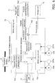
- Fig. 5 is a diagram illustrating a structure of the elapsed time counting unit.
- the elapsed time counting unit 74 includes an elapsed autonomous travel time counting unit 741, and an elapsed teaching time counting unit 743.
- the elapsed autonomous travel time counting unit 741 counts the elapsed autonomous travel time when the reproduction travel mode is executed.
- the elapsed autonomous travel time is an elapsed time from start of the reproduction travel mode.
- the elapsed autonomous travel time counting unit 741 accumulates a unit elapsed time at each control timing, which is described later, so as to count the elapsed autonomous travel time.
- the unit elapsed time determines the progress speed of the elapsed autonomous travel time.
- the unit elapsed time may be a constant value, or a length thereof may be adjustable in accordance with a predetermined condition.
- a control period of the motors 23a and 23b in the motor driving unit 75 can be used for the unit elapsed time.
- a clock period of the computer system constituting the control unit 7 or a time point used in the computer system as the unit time.
- the unit elapsed time may be defined as the product of an arbitrary variable and the control period, the clock period, or the time described above. The value of the arbitrary variable may be adjusted in this case.
- the elapsed teaching time counting unit 743 counts the elapsed teaching time when the manual operation teaching mode is executed.
- the elapsed teaching time counting unit 743 accumulates a predetermined unit time from start of the manual operation teaching mode, for example, so as to count the elapsed teaching time.
- a control period of the motors 23a and 23b in the motor driving unit 75 for example can be used.
- Fig. 6 is a diagram illustrating a structure of the motor driving unit.
- the motor driving unit 75 includes a drive switching unit 751, a reproduction travel command unit 753, a motor control unit 755, and an operation drive control command calculation unit 757.
- the drive switching unit 751 has three terminals d, e and f.
- the drive switching unit 751 refers to a state of the switching unit 77, and connects the terminal d with the terminal e if the manual operation teaching mode is selected in the switching unit 77. On the other hand, the drive switching unit 751 connects the terminal e with the terminal f if the reproduction travel mode is selected.
- the drive switching unit 751 can output the operation travel control command to the motor control unit 755 when the manual operation teaching mode is executed. It can also output the reproduction travel control command (described later) calculated by the reproduction travel command unit 753 (described later) to the motor control unit 755 when the reproduction travel mode is executed.
- the reproduction travel command unit 753 can refer to the travel route data 500 stored in the storage unit 73.
- the reproduction travel command unit 753 can refer to the elapsed autonomous travel time from the elapsed autonomous travel time counting unit 741. Further, the reproduction travel command unit 753 is connected to the terminal f of the drive switching unit 751.
- the reproduction travel command unit 753 calculates the reproduction travel control command based on the elapsed autonomous travel time and the data stored in the travel route data 500. In this way, the reproduction travel command unit 753 can output the reproduction travel control command to the terminal f of the drive switching unit 751.
- the reproduction travel command unit 753 calculates the reproduction travel control command, it calculates the corrected traveling speed based on the traveling speed (taught speed) stored in the travel route data 500. In other words, the reproduction travel command unit 753 sequentially corrects the traveling speeds stored in the travel route data 500 so as to sequentially calculate the new traveling speeds (corrected traveling speeds).
- the platform portion 1 (the autonomous travel vehicle 100) can travel while assuredly reproducing the taught travel route.
- the details of a structure of the reproduction travel command unit 753 is described later.
- the motor control unit 755 can input, via the drive switching unit 751 (from the terminal e), the operation travel control command (described later) when the manual operation teaching mode is executed. On the other hand, it can input the reproduction travel control command when the reproduction travel mode is executed, via the drive switching unit 751 (from the terminal e).
- the motors 23a and 23b are electrically connected to the motor control unit 755.
- the motor control unit 755 controls the motors 23a and 23b based on the operation travel control command (namely, using the operation travel control command as the travel control command) when the manual operation teaching mode is executed.
- the motor control unit 755 controls the motors 23a and 23b based on the reproduction travel control command (namely, using the reproduction travel control command as the travel control command) when the reproduction travel mode is executed.
- the motor control unit 755 controls the motors 23a and 23b, it monitors the rotation speeds and the rotation amounts of the motors 23a and 23b measured by the encoders 231a and 231b. Further, the motor control unit 755 controls the motors 23a and 23b by feeding back the rotation speeds and the rotation amounts of the motors 23a and 23b (as a feedback control).
- a motor control device or the like that utilizes a feedback control theory can be used as the motor control unit 755.
- the operation travel control command calculation unit 757 can input the rotation amounts and/or the rotation directions of the operation handles 51a and 51 b of the operation portion 5, so as to calculate the operation travel control command based on the rotation amounts and/or the rotation directions. In addition, the operation travel control command calculation unit 757 outputs the operation travel control command to the terminal d of the drive switching unit 751 when the manual operation teaching mode is executed.
- the operation travel control command calculation unit 757 outputs the operation travel control command to the taught data generating unit 71 when the manual operation teaching mode is executed.
- the operation travel control command is obtained by digitizing the rotation amounts and/or the rotation directions of the operation handles 51a and 51b.
- the operation travel control command can be a value corresponding to a ratio to the maximum rotation amount of the operation handle 51a or 51 b with a positive or negative sign determined by the rotation direction of the operation handle 51a or 51b.
- the motor control unit 755 can determine the rotation speed of the motor 23a or 23b by multiplying the value indicated in the operation travel control command by the maximum rotation speed of the motor 23a or 23b determined in advance in the motor control unit 755.
- Fig. 7 is a diagram illustrating a structure of the reproduction travel command unit.
- the reproduction travel command unit 753 includes an arrival position prediction unit 7531, a corrected speed calculation unit 7533, and a reproduction travel command calculation unit 7535.
- the arrival position prediction unit 7531 predicts a position to which the platform portion 1 is predicted to move in a predetermined time when the reproduction travel mode is executed. In this embodiment, the arrival position prediction unit 7531 predicts the predicted arrival position, the predicted direction angle, and a straight arrival prediction point.
- the predicted arrival position is a position predicted based on the traveling speed and the arrival time stored in the travel route data 500.
- the predicted arrival position indicates a position that the platform portion 1 (the autonomous travel vehicle 100) is predicted to reach when using the traveling speed and the arrival time stored in the travel route data 500 that may contain a measurement error.
- the predicted direction angle is an angle indicating a direction at the predicted arrival position, which is predicted based on the traveling speed and the arrival time stored in the travel route data 500.
- the predicted direction angle indicates an angle that predicts which direction the platform portion 1 faces at the predicted arrival position when the travel route data 500 may have a measurement error and as well as the platform portion 1 turns using the traveling speed and the arrival time stored in the travel route data 500 (namely, posture).
- the straight arrival prediction point is a point (position) that the platform portion 1 (the autonomous travel vehicle 100) is predicted to reach when it travels straight from the current position.
- the straight arrival prediction point is used for evaluating whether or not the platform portion 1 (the autonomous travel vehicle 100) will cross the travel route when it deviates from the travel route and travels straight without changing its direction.
- the straight arrival prediction point is determined to be a position that is a predetermined distance away from the center C (described later) of the platform portion 1 (the autonomous travel vehicle 100) in the travel direction.
- the corrected speed calculation unit 7533 sequentially corrects the traveling speeds stored in the travel route data 500 so as to calculate the corrected traveling speed.
- the corrected speed calculation unit 7533 performed two types of traveling speed corrections: (i) the traveling speed correction based on the predicted traveling distance and a required traveling distance; and (ii) the traveling speed correction to join the travel route.
- the corrected speed calculation unit 7533 performs the traveling speed correction based on the predicted traveling distance, which is a distance between the current position of the platform portion 1 (the autonomous travel vehicle 100) and the predicted arrival position predicted by the arrival position prediction unit 7531, and a distance (required traveling distance), which is required to reach an arrival target subgoal point that corresponds to the target point to be reached by the platform portion 1 (the autonomous travel vehicle 100).
- the corrected speed calculation unit 7533 performs the traveling speed correction by calculating a corrected parallel speed component (described later) that includes a travel route correction speed component (described later), based on a travel route error between the planned travel route and the platform portion 1 (the autonomous travel vehicle 100), and a parallel speed component V C , which is described later.
- the travel route correction speed component is a speed component that causes the platform portion 1 to turn towards the direction to approach the travel route.
- the corrected speed calculation unit 7533 first performs the traveling speed correction based on the predicted traveling distance and the required traveling distance, and then performs the traveling speed correction to join the travel route on the corrected traveling speed. In this way, even if the platform portion 1 (the autonomous travel vehicle 100) is at a position deviating from the travel route, it can join the travel route and reach the target point to be reached (the arrival target subgoal point).
- the reproduction travel command calculation unit 7535 calculates the reproduction travel control command as the travel control command, when the reproduction travel mode is executed. In this embodiment, the reproduction travel command calculation unit 7535 calculates the reproduction travel control command (the travel control command) based on the traveling speed corrected by the corrected speed calculation unit 7533 (the corrected traveling speed).
- the corrected speed calculation unit 7533 can correct the error of the travel route data 500 in accordance with the actual travel.
- the reproduction travel command calculation unit 7535 can calculate the reproduction travel control command (travel control command) that enables the autonomous travel vehicle 100 to travel while assuredly reproducing the original taught travel route.
- a travel principle of the autonomous travel vehicle 100 (the platform portion 1) including the opposed two-wheel differential type traveling unit 2 is described.
- a center C of the platform portion 1 (the autonomous travel vehicle 100) and a distance between the main wheel 21a and the main wheel 21b (a vehicle width 2d) are defined in the platform portion 1 (the autonomous travel vehicle 100).
- a distance between the center C and the main wheel 21a or 21b is defined as d.
- Fig. 8 is a diagram illustrating the definitions of the center of the platform portion (the autonomous travel vehicle) and the vehicle width.
- Fig. 9 is a diagram illustrating a turning of the platform portion (the autonomous travel vehicle).
- the center C of the platform portion 1 (the autonomous travel vehicle 100) turns with the curvature radius ⁇ .
- an outer main wheel in the turning (the main wheel 21a in the case of turning illustrated in Fig. 9 ) turns with a curvature radius p+d
- an inner main wheel in the turning (the main wheel 21b) turns with a curvature radius p-d.
- the platform portion 1 (the autonomous travel vehicle 100) moves from the subgoal point P i to the subgoal point P i+1 , the center C moves by a distance ⁇ , the outer main wheel 21a moves by a distance ( ⁇ +d) ⁇ , and the inner main wheel 21b moves by a distance ( ⁇ -d) ⁇ .
- the movement distance ( ⁇ +d) ⁇ of the outer main wheel 21 a is different from the movement distance ( ⁇ -d) ⁇ of the inner main wheel 21b. In this way, by differentiating between movement distances (traveling speeds) of the pair of main wheels 21a and 21b, the platform portion 1 (the autonomous travel vehicle 100) equipped with the opposed two-wheel differential type traveling unit 2 can turn.
- the movement distance ⁇ of the center C can be defined as a center speed V C
- the movement distance ( ⁇ +d) ⁇ of the main wheel 21a can be defined as a first traveling speed V 1
- the movement distance ( ⁇ -d) ⁇ of the main wheel 21b can be defined as a second traveling speed V 2 .
- the first traveling speed V 1 and the second traveling speed V 2 have a common speed component ⁇ and a speed component d ⁇ . Further, the first traveling speed V 1 and the second traveling speed V 2 are obtained by adding or subtracting the speed component d ⁇ to or from the speed component ⁇ . Further, whether to add or subtract d ⁇ to or from ⁇ to obtain the first traveling speed V 1 or the second traveling speed V 2 depends on a turning direction (turning left or right) of the platform portion 1 (the autonomous travel vehicle 100).
- the speed component ⁇ of the two speed components is the same as the speed V C of the center C.
- the speed component ⁇ is a speed that determines the speed of the center C (the center speed), and hence it is referred to as the "parallel speed component V C ".
- the speed component d ⁇ is a speed causing a traveling speed difference between the first traveling speed V 1 and the second traveling speed V 2 so that the platform portion 1 can turn, and hence it is referred to as a "turning speed component V R ".
- the turning speed component V R expressed as d ⁇ can be expressed using (d/ ⁇ )V C , the parallel speed component V C , and a turning radius (curvature radius) ⁇ .
- the travel route data 500 stores a traveling speed corresponding to the parallel speed component V C
- the turning speed component V R can be calculated from the traveling speed and the turning radius (curvature radius) ⁇ stored in the travel route data 500.
- the travel route data 500 stores the travel curvature radii ( ⁇ 1 , ⁇ 2 , ...) (described later) when the platform portion 1 (the autonomous travel vehicle 100) passes the subgoal points, in association with the subgoal points.
- the travel curvature radius (turning radius) ⁇ at each subgoal point may be calculated from the subgoal points stored in the travel route data 500 using the method described later.
- Fig. 10A is a flowchart illustrating an operation of the autonomous travel vehicle.
- the operator operates the operation portion 5 so that the autonomous travel vehicle 100 travels and that the travel route is taught to the autonomous travel vehicle 100, and then taught travel route is reproduced when the reproduction travel mode is executed.
- the taught data generating unit 71 first obtains the travel route data 500 of the travel route that the autonomous travel vehicle 100 passes when the operator operates the autonomous travel vehicle 100, and stores the travel route data 500 in the storage unit 73 (Step S1).
- Step S1 A method of acquiring the travel route data 500 in Step S1 will be described later in detail.
- the travel mode of the autonomous travel vehicle 100 is switched to the reproduction travel mode by the setting unit 53 or the like. Further, the autonomous travel vehicle 100 autonomously travels while reproducing the travel route based on the travel route data 500 (Step S2).
- the corrected speed calculation unit 7533 sequentially corrects the traveling speeds stored in the travel route data 500 (namely, calculates the corrected traveling speeds). Further, the reproduction travel command calculation unit 7535 calculates the reproduction travel control command based on the corrected traveling speed (the corrected traveling speed).
- the traveling speeds stored in the travel route data 500 are sequentially corrected, and the travel control command (the reproduction travel control command) is calculated based on the corrected traveling speeds (the corrected traveling speeds).
- the travel control command (the reproduction travel control command) is calculated based on the corrected traveling speeds (the corrected traveling speeds).
- Fig. 10B is a flowchart illustrating a method of obtaining the travel route data.
- the travel mode of the autonomous travel vehicle 100 is set to the manual operation teaching mode (Step S11). Switching of the travel mode to the manual operation teaching mode is made, for example by the operator operating the setting unit 53 of the operation portion 5.
- the switching unit 77 of the control unit 7 is informed that the travel mode has changed to the manual operation teaching mode. Then, the switching unit 77 instructs the drive switching unit 751 of the motor driving unit 75 to connect the terminal d with the terminal e in the drive switching unit 751. In this way, the operation travel control command, which is calculated based on the rotation amounts and the rotation directions of the operation handles 51a and 51 b of the operation portion 5, is input to the motor control unit 755.
- the operator can manually operate the autonomous travel vehicle 100 by adjusting the rotation amounts and the rotation directions of the operation handles 51 a and 51b.
- the elapsed teaching time counting unit 743 starts counting the elapsed teaching time.
- the elapsed teaching time counting unit 743 accumulates the control period of the motors 23a and 23b as the unit time from start of the manual operation teaching mode so as to count the elapsed teaching time.
- counting of the elapsed teaching time may be started by an arbitrary starting instruction by the operator.
- the operator uses the operation portion 5 to manually operate the autonomous travel vehicle 100.
- the taught data generating unit 71 obtains positions on the movement plane that the autonomous travel vehicle 100 passes via the operation of the operator as the taught subgoal points every predetermined time (Step S12).
- the taught data generating unit 71 instructs the position estimating unit 72 to estimate a current position (coordinates of the subgoal point) of the autonomous travel vehicle 100 on the movement coordinate system. Further, the position estimating unit 72 responds to the instruction and outputs the position (subgoal point) expressed by coordinate values as the taught subgoal point to the taught data generating unit 71.
- the taught data generating unit 71 when the taught data generating unit 71 obtains the taught subgoal point, it obtains information about a current direction (direction angle ⁇ ) of the autonomous travel vehicle 100 (the platform portion 1) at the taught subgoal point (Step S13).
- the current direction angle ⁇ can be estimated by map matching between the environment map and the local map performed by the position estimating unit 72.
- the taught data generating unit 71 After obtaining the taught subgoal point and the direction angle at the taught subgoal point, the taught data generating unit 71 obtains the elapsed teaching time when the taught subgoal point is obtained, from the elapsed teaching time counting unit 743 (Step S 14).
- the taught data generating unit 71 obtains the speed of the autonomous travel vehicle 100 (traveling speed) when passing the obtained subgoal point, as the taught speed (Step S 15).
- the taught data generating unit 71 receives from the operation travel control command calculation unit 757 the operation travel control command calculated from the rotation amounts and the rotation directions of the operation portion 5 by the operation by an operator, and calculated by the operation drive control command calculation unit 757. Then, the taught data generating unit 71 obtains the received operation travel control command as the taught speed.
- the taught data generating unit 71 may calculate the taught speed from the rotation amounts per unit time of the motors 23a and 23b or the main wheels 21a and 21b. Further, the taught data generating unit 71 may calculate the taught speed from a change of the position of the autonomous travel vehicle 100 per unit time, which is estimated by the position estimating unit 72. Thus, through an appropriate method, the taught data generating unit 71 can obtain the taught speed.
- the parallel speed component V C corresponding to the center speed V C of the platform portion 1 (the autonomous travel vehicle 100) equipped with the opposed two-wheel differential type traveling unit 2 is stored in the travel route data 500. Accordingly, the taught data generating unit 71 calculates a taught parallel speed component from the taught speed (corresponding to the rotation speed of the main wheels 21a and 21b) by the method described above in the description of the travel principle of the traveling unit 2.
- the travel route data 500 is not limited to store the taught parallel speed component, but may store the first traveling speed V 1 (described later) and the second traveling speed V 2 (described later) as taught speeds.
- the first traveling speed V 1 refers to the rotation speed of the main wheel 21a.
- the second traveling speed V 2 refers to the rotation speed of the main wheel 21b.
- Step S12 to S 15 By executing Steps S12 to S 15, the taught subgoal point, the elapsed teaching time when the taught subgoal point is obtained, the taught parallel speed component when the taught subgoal point is obtained, and the direction angle at the taught subgoal point are obtained.
- the taught data generating unit 71 associates the taught subgoal point, the elapsed teaching time, the taught parallel speed component, and the direction angle with each other, so as to generate a travel route data unit 500-k as illustrated in Fig. 11A (Step S16).
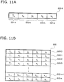
- Fig. 11A is a diagram illustrating an example of the travel route data unit.
- execution order of Steps S12 to S15 may be appropriately changed.
- the travel route data unit 500-k illustrated in Fig. 11A is a travel route data unit generated with respect to the k-th obtained taught subgoal point.
- the travel route data unit 500-k includes an arrival time storage area 501-k, a subgoal point storage area 503-k, a direction angle storage area 505-k, and a taught speed storage area 507-k.
- the arrival time storage area 501-k, the subgoal point storage area 503-k, the direction angle storage area 505-k, and the taught speed storage area 507-k are linked in the lateral direction of the paper plane.
- the arrival time storage area 501-k of the travel route data unit 500-k stores the elapsed teaching time when the k-th taught subgoal point is obtained, as an arrival time (T k ).
- the subgoal point storage area 503-k stores coordinate values (x k , y k ) of the k-th obtained taught subgoal point.
- the direction angle storage area 505-k stores a direction angle ( ⁇ k ) of the k-th obtained taught subgoal point.
- the taught speed storage area 507-k stores a taught speed (the taught parallel speed component) (v k ) at the k-th taught subgoal point (x k , y k ).
- the taught data generating unit 71 After generating the travel route data unit 500-k, the taught data generating unit 71 stores the travel route data unit 500-k in the storage unit 73 (Step S 17).
- the travel route data unit 500-k When the travel route data unit 500-k is stored in the storage unit 73, if some travel route data units are already stored in the storage unit 73 so that the travel route data 500 ( Fig. 11B ) is formed, the travel route data unit 500-k generated this time is added to the end of the stored travel route data 500.
- the taught data generating unit 71 After storing the travel route data unit 500-k in the storage unit 73, the taught data generating unit 71 checks whether or not the teaching of the travel route by the operator's manual operation is finished before the next taught subgoal point is obtained (Step S18).
- the determination whether or not the teaching of the travel route is finished it is possible, for example, to provide the operation portion 5 with a switch (not shown) that informs the taught data generating unit 71 that the teaching of the travel route is finished. This allows the operator to be able to operate the switch to inform that the teaching of the travel route is finished.
- the taught data generating unit 71 may determine that the teaching of the travel route is finished when it is detected for a preset constant time that the rotation amounts of the operation handles 51 a and 51b are zero (indicating no operation). Alternatively, it is possible to determine whether or not the teaching of the travel route is finished by other methods that detect that the operator has finished the operation of the autonomous travel vehicle 100.
- Step S18 When it is determined that the teaching of the travel route by the operator's manual operation is finished ("Yes" in Step S18), the taught data generating unit 71 proceeds to Step S19.
- Step S18 if it is determined that the teaching of the travel route by the operator's manual operation continues ("No" in Step S18), the process returns to Step S12, so as to continue the generation and storing of the travel route data unit 500-k.
- the taught data generating unit 71 can continue generating and storing the travel route data unit 500-k as long as the teaching of the travel route continues (namely, as long as the manual operation teaching mode is executed).
- Fig. 11B is a diagram illustrating an example of the travel route data.
- n+1 travel route data units 500-0, 500-1, 500-2, 500-3, ..., 500-n-1, and 500-n are linked to stack from up to down on the paper plane in the execution order.
- the taught data generating unit 71 can generate the travel route data 500 as illustrated in Fig. 11B , which stores the subgoal points, the arrival times when the subgoal points are obtained, and the traveling speeds at the subgoal points, in association with each other.
- the taught data generating unit 71 calculates the travel curvature radii ⁇ when the platform portion 1 (the autonomous travel vehicle 100) passes the subgoal points, and the calculated travel curvature radii are stored in the travel route data 500 by associating with the subgoal points (Step S 19).
- the travel curvature radius ⁇ can be calculated as a radius of a circle formed of three subgoal points including, for example, a first target subgoal point for which the travel curvature radius ⁇ is calculated, a second target subgoal point that is apart from the first target subgoal point by a predetermined distance and is stored before the first target subgoal point, and a third target subgoal point that is apart from the first target subgoal point by a predetermined distance and is stored after the first target subgoal point.
- the travel curvature radius ⁇ can be calculated by a simple calculation.
- predetermined distance it is preferred to select an appropriate value as the "predetermined distance" when selecting the subgoal point for calculating the travel curvature radius ⁇ . It is because if the predetermined distance is too small, the influence of the measurement error of the subgoal point cannot be sufficiently reduced.
- the travel curvature radius ⁇ may be unable to sufficiently express the travel route indicated in the travel route data 500.
- the travel curvature radius ⁇ is regarded to be infinite (namely, it is regraded that a partial travel route at the first taught subgoal point is a straight line).
- the taught data generating unit 71 sequentially calculates the travel curvature radii for all the subgoal points stored in the travel route data 500 by the calculation method described above, and stores the travel curvature radii ( ⁇ 0 , ⁇ 1 , ... ⁇ n ) at respective subgoal points in the travel route data unit 500-0, ... 500-n, respectively.
- the travel route data 500 as illustrated in Fig. 11C is eventually generated.
- Fig. 11C is a diagram illustrating the travel route data storing the travel curvature radii.
- Fig. 11D is a diagram illustrating the travel route data unit including the travel curvature radius storage area.
- Steps S11 to S18 illustrated in Fig. 10B it is possible to store the taught travel route having a concept of time in the travel route data 500 via the operation of the operator.
- Step S2 of the flowchart illustrated in Fig. 10A is described.
- the travel mode is switched to the reproduction travel mode.
- the travel mode can be switched to the reproduction travel mode by an operation of the setting unit 53.
- the autonomous travel vehicle 100 reproduces and travels the travel route, while reproducing the taught operation based on the travel route data 500 (execution of the reproduction travel mode).
- the corrected speed calculation unit 7533 of the reproduction travel command unit 753 sequentially corrects the traveling speeds stored in the travel route data 500 so as to calculate the corrected traveling speeds by the method described later.
- the reproduction travel command calculation unit 7535 calculates the reproduction travel control command based on the corrected traveling speed. After calculating the reproduction travel control command, the reproduction travel command unit 753 outputs the calculated reproduction travel control command as the travel control command to the motor control unit 755 via the drive switching unit 751.
- the autonomous travel vehicle 100 can travel while assuredly reproducing the taught travel route.
- traveling speed correction when the reproduction travel mode is executed is described.
- either or both of two traveling speed corrections are performed, which include (i) traveling speed correction based on the predicted traveling distance and the required traveling distance, and (ii) traveling speed correction to join the travel route.
- the parallel speed component V C and the turning speed component V R described above are corrected in the traveling speed correction described below. Then, by using a corrected parallel speed component V C ' as the corrected parallel speed component V C and a corrected turning speed component V R ' as the corrected turning speed component V R , the corrected traveling speed for the first traveling speed V 1 and the corrected traveling speed for the second traveling speed V 2 are calculated.
- the travel route data 500 stores the parallel speed component V C and the travel curvature radius ⁇ . Accordingly, the turning speed component V R is calculated from the relationship described above by using the parallel speed component V C and the travel curvature radius ⁇ .
- the traveling speed correction based on the predicted traveling distance and the required traveling distance is described.
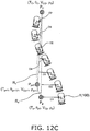
- the correction based on the predicted traveling distance and the required traveling distance there are a case where a distance between the subgoal points (the current subgoal point P p and the arrival target subgoal point P O ) stored in the travel route data 500 is defined as the required traveling distance as illustrated in Fig. 12A , and a case where a distance between a current position P of the platform portion 1 and the target point to be reached (corresponding to the arrival target subgoal point P O ) is defined as the required traveling distance as illustrated in Fig. 12B .
- Fig. 12A is a diagram schematically illustrating the traveling speed correction when the required traveling distance is defined as the distance between the current subgoal point and the arrival target subgoal point.
- Fig. 12B is a diagram schematically illustrating the traveling speed correction when the required traveling distance is defined as the distance between the current position and the arrival target subgoal point.
- the traveling speed correction when the distance between the subgoal points stored in the travel route data 500 is defined as the required traveling distance is described with reference to Fig. 12A .
- the example illustrated in Fig. 12A is the case where the current position P of the platform portion 1 (the autonomous travel vehicle 100) is a position corresponding to one of the subgoal points stored in the travel route data 500 (the current subgoal point P p (described later)).
- the corrected speed calculation unit 7533 first determines the current subgoal point that is a subgoal point corresponding to the current position P of the platform portion 1.
- the corrected speed calculation unit 7533 sets the current subgoal point P p to the subgoal point associated with the arrival time when the current elapsed autonomous travel time becomes the time point corresponding to the arrival time stored in the travel route data 500.
- an appropriate current subgoal point can be selected.
- the arrival position prediction unit 7531 reads the current traveling speed (a current parallel speed component V Cp ) associated with the current subgoal point P p from the travel route data 500. Then, the arrival position prediction unit 7531 calculates a current turning speed component V Rp using the read current parallel speed component V Cp and a current travel curvature radius ⁇ p associated with the current subgoal point.
- the arrival position prediction unit 7531 calculates the first traveling speed V 1 and the second traveling speed V 2 using the current parallel speed component V Cp and the current turning speed component V Rp . In addition, the arrival position prediction unit 7531 reads from the travel route data 500 a next arrival time To which is the time at which the platform portion 1 reaches the target point.
- a position corresponding to the subgoal point stored in a travel route data unit 500-(p+1) next to a travel route data unit 500-p storing the current subgoal point P p is the target point of the platform portion 1.
- the subgoal point stored in the next travel route data unit 500-(p+1) is the arrival target subgoal point P O .
- the next arrival time T O is the arrival time stored in the travel route data unit 500-(p+1).
- the arrival position prediction unit 7531 uses the calculated first traveling speed V 1 and second traveling speed V 2 to predict a predicted arrival position P O ' that is predicted to be reached by the platform portion 1 in a time between a current arrival time T p (corresponding to the elapsed autonomous travel time) associated with the current subgoal point P p and the next arrival time To, and a predicted direction angle ⁇ O ' indicating a direction of the platform portion 1 at the predicted arrival position P O '.
- the corrected speed calculation unit 7533 calculates a required traveling distance L r as a distance between the current subgoal point P p and the arrival target subgoal point P O . In addition, the corrected speed calculation unit 7533 calculates a predicted traveling distance L e as a distance between the current position P of the platform portion 1 and the predicted arrival position P O '.
- the corrected speed calculation unit 7533 calculates a target direction angle change ⁇ as a difference between an arrival target direction angle ⁇ O associated with the arrival target subgoal point P O and a first current direction angle ⁇ p1 associated with the current subgoal point P p .
- the corrected speed calculation unit 7533 calculates a difference between the predicted direction angle ⁇ O ' and a second current direction angle ⁇ P2 indicating the current direction of the platform portion 1 as a predicted direction angle change ⁇ e .
- the corrected speed calculation unit 7533 calculates the corrected parallel speed component V C ' that is corrected such that the current parallel speed component V Cp is increased. On the other hand, if the predicted traveling distance L e is larger than the required traveling distance L r , the corrected speed calculation unit 7533 calculates the corrected parallel speed component V C ' that is corrected such that the current parallel speed component V Cp is decreased.
- the corrected speed calculation unit 7533 calculates the product of the current parallel speed component V Cp and a ratio (first ratio) between the required traveling distance L r and the predicted traveling distance L e as the corrected parallel speed component V C ' that is a corrected speed of the parallel speed component.
- the corrected speed calculation unit 7533 calculates the corrected turning speed component V R ' that is corrected such that the current turning speed component V Rp is increased. On the other hand, if the predicted direction angle change ⁇ e is larger than the target direction angle change ⁇ , the corrected speed calculation unit 7533 calculates the corrected turning speed component V R ' that is corrected such that the current turning speed component V Rp is decreased.
- the corrected speed calculation unit 7533 calculates the product of the current turning speed component V Rp and a ratio (second ratio) between the target direction angle change ⁇ and the predicted direction angle change ⁇ e as the corrected turning speed component V R '.
- the corrected parallel speed component V C ' is calculated based on the predicted traveling distance L e and the required traveling distance L r , even if the travel route data 500 has an error generated by a measurement error, the error of the travel route data 500 can be corrected in accordance with the actual travel.
- the autonomous travel vehicle 100 can travel while assuredly reproducing the taught travel route.
- the corrected turning speed component V R ' is calculated based on the target direction angle change ⁇ and the predicted direction angle change ⁇ e , even if the travel route data 500 has an error generated by a measurement error, the error of the travel route data 500 can be corrected in accordance with the actual travel. As a result, when the autonomous travel vehicle 100 travels along the travel route while changing its direction, it can travel while assuredly reproducing the taught travel route and the direction.
- Fig. 13A is a diagram illustrating an example of the reproduction travel locus when the traveling speed correction is performed by using the distance between the current subgoal point and the arrival target point subgoal point as the required traveling distance.
- the autonomous travel vehicle 100 of this embodiment can travel while assuredly reproducing the taught travel route and the taught direction of the platform portion 1 (the autonomous travel vehicle 100).
- Fig. 12A illustrates an example in which the second current direction angle ⁇ P2 indicating a direction of the platform portion 1 at the current position corresponds to the first current direction angle ⁇ p1 associated with the current subgoal point P p , but the traveling speed correction described above can be performed in the same manner even if the first current direction angle ⁇ p1 is different from the second current direction angle ⁇ P2 .
- the traveling speed correction in the case where the distance between the current position P of the platform portion 1 and the target point to be reached is the required traveling distance L r .
- the traveling speed correction in the case where the platform portion 1 travels without changing its direction (namely, travels straight).
- the correction described below can also be performed in the case where the platform portion 1 turns.
- the traveling speed correction in the case where the distance between the current position P of the platform portion 1 and the target point to be reached is the required traveling distance L r is different from the traveling speed correction described above only in the point that the required traveling distance L r is the distance between the current position P of the platform portion 1 and the target point to be reached, and a basic concept of other part is the same as the traveling speed correction described above.
- the corrected speed calculation unit 7533 first determines the current position P of the platform portion 1 and the target point to be reached. The corrected speed calculation unit 7533 determines the current position P of the platform portion 1 based on the information about positions output from the position estimating unit 72.
- the corrected speed calculation unit 7533 sets the subgoal point stored in the travel route data unit 500-(p+1) next to the travel route data unit storing the arrival time corresponding to the current elapsed autonomous travel time (the travel route data unit 500-p in the example illustrated in Fig. 12B ) as the target point to be reached (the arrival target subgoal point P O ).
- the corrected speed calculation unit 7533 calculates the required traveling distance L r as the distance between the current position P of the platform portion 1 and the arrival target subgoal point P O .
- the corrected speed calculation unit 7533 calculates the product of the current parallel speed component V Cp stored in the travel route data unit 500-p and a ratio (third ratio) between the required traveling distance L r and the predicted traveling distance L e as the corrected parallel speed component V C '.
- the corrected speed calculation unit 7533 defines a distance between the predicted arrival position P O ' and the arrival target subgoal point P O as Diff (positive value), and sets the value obtained by adding or subtracting the Diff to or from the predicted traveling distance L e as the required traveling distance L r .
- the corrected speed calculation unit 7533 adds Diff if the predicted arrival position P O ' is before the arrival target subgoal point P O in the travel direction, while it subtracts Diff if the predicted arrival position P O ' is ahead the arrival target subgoal point P O .
- the corrected speed calculation unit 7533 can calculate the corrected parallel speed component V C ' so as to increase the traveling speed stored in the travel route data 500 (the current parallel speed component V Cp ).
- the corrected speed calculation unit 7533 can calculate the corrected parallel speed component V C ' so as to decrease the traveling speed stored in the travel route data 500 (the current parallel speed component V Cp ).
- the correction of the turning speed component V R is performed in the same manner as the correction described above in the speed correction in the case where the distance between the subgoal points is the required traveling distance.
- Fig. 13B is a diagram illustrating an example of the reproduction travel locus when the traveling speed correction is performed using the distance between the current position and the arrival target subgoal point as the required traveling distance.
- the corrected speed calculation unit 7533 performs the speed correction by setting Diff to zero.
- the angle between the line segment PP O' and the line segment P p P O becomes a predetermined value or larger means that the platform portion 1 (the autonomous travel vehicle 100) further deviates from the travel route if it autonomously travels at the corrected speed.
- the traveling speed correction based on the required traveling distance L r and the predicted traveling distance L e , based on a condition such as the current position P of the platform portion 1, a traveling state of the platform portion 1 (the autonomous travel vehicle 100), or the like.
- the traveling speed correction such that the platform portion 1 (the autonomous travel vehicle 100) can join the travel route when the reproduction travel mode is executed and if the platform portion 1 (the autonomous travel vehicle 100) deviates from the planned travel route.
- the traveling speed correction to join the travel route is performed based on a travel route error D (described later) indicating a deviation between the platform portion 1 (the autonomous travel vehicle 100) and the travel route.
- a travel route error D (described later) indicating a deviation between the platform portion 1 (the autonomous travel vehicle 100) and the travel route.
- FIG. 12C is a diagram schematically illustrating the traveling speed correction in the case where the travel route error is the distance between the virtual travel route and the current position P of the platform portion 1.
- Fig. 12D is a diagram schematically illustrating the traveling speed correction in the case where the travel route error is the distance between the virtual travel route and the straight arrival prediction point. The cases are respectively described below.
- the traveling speed correction to join the travel route in the case where the travel route error D is the distance between the virtual travel route R V and the current position P of the platform portion 1 is described with reference to Fig. 12C .
- the corrected speed calculation unit 7533 first calculates the corrected parallel speed component V C' and the corrected turning speed component V R' using the above-described traveling speed correction method based on the predicted traveling distance L e and the required traveling distance L r .
- the distance between the current position P of the platform portion 1 and a subgoal point P p+1 associated with a next arrival time T p+1 is used as the required traveling distance L r .
- a difference between the direction angle ⁇ p+1 associated with the subgoal point P p+1 and the second current direction angle ⁇ P2 indicating the current direction of the platform portion 1 is used as the target direction angle change ⁇ .
- the corrected speed calculation unit 7533 calculates the corrected parallel speed component V C ' and the corrected turning speed component V R ' using the current subgoal point P p as the next subgoal point P p+1 and using a current parallel speed component V Cp+1 by the method described above.
- the current subgoal point is switched from the subgoal point P p to the subgoal point P p+1 when the current position of the platform portion 1 becomes a position P2.
- a predetermined ratio an appropriate ratio is selected so that the autonomous travel vehicle 100 can travel forward or backward at a sufficient traveling speed and can quickly join the travel route.
- the travel route correction speed component can be calculated without making the first traveling speed V 1 and/or the second traveling speed V 2 a maximum speed or higher, or a minimum speed or lower.
- the corrected speed calculation unit 7533 calculates a first travel route correction speed component V C21 ' and a second travel route correction speed component V C22 ' as corrected speeds joining the travel route respectively for the first traveling speed V 1 and the second traveling speed V 2 based on the travel route error D.
- the corrected speed calculation unit 7533 first calculates the travel route error D.
- the travel route error D is supposed to be the distance between the virtual travel route R V and the current position P of the platform portion 1 (estimated from the information about positions in the position estimating unit 72).
- the virtual travel route R V is supposed to be a travel route expressed by a straight line connecting the current subgoal point P p and the arrival target subgoal point P O apart from the current subgoal point P p by a predetermined distance (the arrival target subgoal point P O is not limited to the next subgoal point P p+1 as illustrated in Fig. 12C ).
- the travel route correction speed components (the first travel route correction speed component V C21 ' and the second travel route correction speed component V C22 ') can be calculated by a simpler calculation.
- the corrected speed calculation unit 7533 sets the travel route error D as a negative value if the autonomous travel vehicle 100 exists on the right side of the travel route, while it sets the travel route error D as a positive value if the autonomous travel vehicle 100 exists on the left side of the travel route.
- the corrected speed calculation unit 7533 sets the travel route error D as a positive value if the autonomous travel vehicle 100 exists on the right side of the travel route, while it sets the travel route error D as a negative value if the autonomous travel vehicle 100 exists on the left side of the travel route.
- the corrected speed calculation unit 7533 uses the second parallel speed component V C2 so as to calculate the first travel route correction speed component V C21 ' and the second travel route correction speed component V C22 '. Specifically, the corrected speed calculation unit 7533 calculates the first travel route correction speed component V C21 ' as the product of the second parallel speed component V C2 and a first constant K 1 .
- the first constant K 1 has a value determined by a function that monotonically increases in a range from 0 to 1 along with an increase of travel route errors D1, D2, and so on.
- a function expressed by the graph illustrated in Fig. 14 can be used as the function described above, for example.
- Fig. 14 illustrates a graph of an example of the function that determines the first constant.
- a value of the function illustrated in Fig. 14 becomes 0.5 when the travel route error D is zero, and it does not become smaller than zero or larger than one over the entire range of the travel route error D.
- the function that determines the first constant K 1 is not limited to the one comprised of two parabolas as illustrated in Fig. 14 .
- the function that determines the first constant K 1 may be a function expressing a straight line increasing monotonically along with an increase of the travel route error D (a straight line having a positive gradient with respect to the travel route error D).
- the function may be a cubic function of the travel route error D.
- the function can be appropriately determined depending on a turning degree given to the platform portion 1 (the autonomous travel vehicle 100) with respect to a value of the travel route error D.
- the second travel route correction speed component V C22' is calculated as the product of the second parallel speed component V C2 and a second constant K 2 .
- the corrected speed calculation unit 7533 calculates the travel route error D using the straight line connecting the next subgoal point P p+1 and the arrival target subgoal point P O as the new virtual travel route R V .
- the corrected speed calculation unit 7533 calculates the first traveling speed V 1 and the second traveling speed V 2 , by using a corrected parallel speed component V C " including the first travel route correction speed component V C21 ' or the second travel route correction speed component V C22' and the corrected turning speed component V R '.
- the corrected speed calculation unit 7533 calculates the first traveling speed V 1 and the second traveling speed V 2 including the first travel route correction speed component V C21 ' or the second travel route correction speed component V C22 ', and hence the first traveling speed V 1 and the second traveling speed V 2 further includes a speed difference corresponding to the difference between the first travel route correction speed component V C21 ' and the second travel route correction speed component V C22 '.
- the platform portion 1 (the autonomous travel vehicle 100) is further driven to turn to join the travel route based on a value of the travel route error D.
- the travel route error D has a negative value (e.g., when the platform portion 1 is traveling forward and exists on the right side of the travel route), as to a relationship between the first travel route correction speed component V C21 ' and the second travel route correction speed component V C22 ', the first travel route correction speed component V C21' becomes smaller than the second travel route correction speed component V C22 ', It is because in this case, the first constant becomes smaller than 0.5 (as a result, the second constant becomes larger than 0.5). As a result, the platform portion 1 turns left (counterclockwise) in the travel direction (forward direction) (clockwise when traveling backward).
- the travel route error D has a positive value (e.g., when the platform portion 1 is traveling forward and exists on the left side of the travel route), as to a relationship between the first travel route correction speed component V C21' and the second travel route correction speed component V C22 ', the first travel route correction speed component V C21 ' is larger than the second travel route correction speed component V C22 ', It is because in this case, the first constant becomes larger than 0.5 (as a result, the second constant becomes smaller than 0.5). As a result, the platform portion 1 turns right (clockwise) in the travel direction (forward direction) (counterclockwise when traveling backward).
- the speed difference between the first travel route correction speed component V C21 ' and the second travel route correction speed component V C22' becomes smaller as the travel route errors D1, D2, ... become closer to zero. It is because when the travel route error D becomes close to zero, both the first constant and the second constant become close to 0.5.
- a turning amount of the autonomous travel vehicle 100 given by the difference between the first travel route correction speed component V C21' and the second travel route correction speed component V C22' becomes small (the curvature radius of the turning travel becomes large), and the turning amount becomes zero when the autonomous travel vehicle 100 has joined the travel route.
- the corrected speed calculation unit 7533 can determine the turning to join the travel route based on the travel route error D and on which side of the travel route the platform portion 1 (the autonomous travel vehicle 100) exists (positive or negative of the travel route error D).
- the autonomous travel vehicle 100 can approach the travel route again. In this way, the autonomous travel vehicle 100 can gradually join the travel route.
- the traveling speed correction to join the travel route illustrated in Fig. 12D is the same as the above-described traveling speed correction to join the travel route except that the travel route error is the distance between the straight arrival prediction point P' (described later) and the virtual travel route R V .
- the straight arrival prediction point P' is a point indicating a position that the platform portion 1 is predicted to reach when it travels straight while maintaining the current direction (direction angle) for a predetermined time.
- the straight arrival prediction point P' is predicted as a point apart from the center C of the platform portion 1 in the travel direction of the platform portion 1 by a predetermined distance L P ', when the autonomous travel vehicle 100 travels forward, as illustrated in Fig. 12D .
- the straight arrival prediction point P' is predicted as a point apart from the center C of the platform portion 1 in the backward travel direction of the platform portion 1 by a predetermined distance L P '.
- the arrival position prediction unit 7531 predicts that the platform portion 1 crosses the travel route and moves to the left side of the travel route if the platform portion 1 travels straight forward maintaining the direction at the position P3 when the platform portion 1 becomes close to the travel route and exists at the position P3.
- the corrected speed calculation unit 7533 calculates the first travel route correction speed component V C21' and the second travel route correction speed component V C22 ', such that a magnitude relationship between the first travel route correction speed component V C21 ' and the second travel route correction speed component V C22' after the position P3 is reversed from the magnitude relationship before the position P3 (at the positions P1 and P2).
- the platform portion 1 existing on the right side of the travel route is driven to turn right so as to travel along the travel route.
- the platform portion 1 (the autonomous travel vehicle 100) can join the travel route more quickly than a case where the distance between the virtual travel route R V and the current position P of the platform portion 1 is used. This is because of the following reason.
- Fig. 13C is a diagram illustrating an example of the reproduction travel route in the case where the travel route error is the distance between the virtual travel route and the current position of the platform portion.
- the platform portion 1 (the autonomous travel vehicle 100) meanders with respect to the travel route so as to gradually approach the travel route. As a result, it takes time for the platform portion 1 to join the travel route.
- the platform portion 1 (the autonomous travel vehicle 100) is driven to turn so as to travel along the travel route before crossing the travel route when the platform portion 1 (the autonomous travel vehicle 100) becomes close to the travel route by a certain degree.
- Fig. 13D is a diagram illustrating an example of the reproduction travel locus when correcting the traveling speed using the distance between the virtual travel route and the straight arrival prediction point as the travel route error.
- Fig. 15A is a diagram illustrating the reproduction travel locus in the example of the reproduction travel without correcting the traveling speed.
- the autonomous travel vehicle 100 travels on the positions deviating from the travel route as the reproduction of the travel route proceeds.
- Fig. 15B illustrates the reproduction travel locus of Comparative Example 2, in which the autonomous travel vehicle 100 of the first embodiment does not perform the traveling speed correction to join the travel route based on the travel route error.
- Fig. 15B is a diagram illustrating the reproduction travel locus in the example in which the traveling speed correction to join the travel route based on the travel route error is not performed.
- the production travel locus of Comparative Example 2 illustrated in Fig. 15B is a reproduction travel locus in a case where the position of the platform portion 1 (the autonomous travel vehicle 100) at start of the reproduction travel mode deviates from the travel route, and the traveling speed correction to join the travel route is not performed.
- the autonomous travel vehicle 100 executes the reproduction travel while maintaining an error between a position of the platform portion 1 (the autonomous travel vehicle 100) at start of the reproduction travel mode and the travel route (particularly in the first half of the travel route). Also in this case, it cannot be said that the autonomous travel vehicle 100 travels assuredly along the taught travel route.
- the autonomous travel vehicle 100 includes the platform portion 1 (an example of the platform portion), the traveling unit 2 (an example of the traveling unit), the storage unit 73 (an example of the storage unit), the arrival position prediction unit 7531 (an example of the arrival position prediction unit), the corrected speed calculation unit 7533 (an example of the corrected speed calculation unit), and the reproduction travel command calculation unit 7535 (an example of the reproduction travel command calculation unit).
- the traveling unit 2 controls the platform portion 1 to travel in accordance with the travel control command.
- the storage unit 73 stores the travel route data 500 (an example of the travel route data).
- the travel route data 500 stores the plurality of subgoal points (an example of the subgoal points) set on the planned travel route, the arrival times (an example of the arrival times) at which the plurality of subgoal points are respectively reached, and the traveling speed (an example of the traveling speed) of the platform portion 1 at the plurality of subgoal points in association with each other.
- the arrival position prediction unit 7531 predicts the predicted arrival position P O ' (an example of the predicted arrival position) of the platform portion 1 based on the traveling speed and the arrival time when the reproduction mode (an example of the reproduction mode) is executed.
- the reproduction mode is a travel mode of traveling autonomously along the travel route based on the travel route data 500.
- the corrected speed calculation unit 7533 calculates the corrected traveling speed (an example of the corrected traveling speed) based on the predicted traveling distance L e (an example of the predicted traveling distance) and the required traveling distance L r (an example of the required traveling distance), when the reproduction mode is executed.
- the predicted traveling distance L e is a distance between the current position P of the platform portion 1 (an example of the current position) and the predicted arrival position P O ' (an example of the predicted arrival position).
- the required traveling distance L r is a traveling distance necessary to reach the arrival target subgoal point P O (an example of the arrival target subgoal point).
- the arrival target subgoal point P O is a subgoal point corresponding to a target point to be reached by the platform portion 1.
- the corrected traveling speed is a corrected speed of the traveling speed.
- the reproduction travel command calculation unit 7535 calculates the reproduction travel control command based on the corrected traveling speed (an example of the reproduction travel control command) as the travel control command when the reproduction mode is executed.
- the arrival position prediction unit 7531 first predicts the predicted arrival position P O '.
- the corrected speed calculation unit 7533 calculates the predicted traveling distance L e from the predicted arrival position P O ' and the current position P.
- the corrected speed calculation unit 7533 calculates the required traveling distance L r necessary to reach the arrival target subgoal point P O .
- the corrected speed calculation unit 7533 calculates the corrected traveling speed based on the predicted traveling distance L e and the required traveling distance L r .
- the reproduction travel command calculation unit 7535 calculates the reproduction travel control command based on the corrected traveling speed, and the reproduction travel control command is used as the travel control command. Further, the traveling unit 2 enables the platform portion 1 to travel based on the reproduction travel control command calculated based on the corrected traveling speed.
- the travel route data 500 stores not only the plurality of subgoal points set on the travel route but also the associated arrival times when reaching the subgoal points and the associated traveling speeds at the subgoal points. In this way, the autonomous travel vehicle 100 reproduces the operation having a concept of time and executes the reproduction travel along the travel route.
- the traveling speed stored in the travel route data 500 is corrected based on the predicted traveling distance and the required traveling distance. In this way, even if the travel route data 500 has a measurement error, the error of the travel route data 500 can be corrected in accordance with the actual traveling. As a result, the autonomous travel vehicle 100 can travel while assuredly reproducing the travel route.
- the required traveling distance L r is the distance between the current position P and the arrival target subgoal point P O .
- the deviation can be reduced before reaching the next target point (the arrival target subgoal point).
- the autonomous travel vehicle 100 further includes the elapsed autonomous travel time counting unit 741 (an example of the elapsed autonomous travel time counting unit).
- the elapsed autonomous travel time counting unit 741 counts the elapsed autonomous travel time from a start of the reproduction mode (an example of the elapsed autonomous travel time).
- the required traveling distance is a distance between the current subgoal point P p (an example of the current subgoal point) and the arrival target subgoal point P O .
- the current subgoal point P p is a subgoal point associated with the arrival time corresponding to the elapsed autonomous travel time.
- the traveling unit 2 may be comprised of a pair of main wheels 21a and 21b (an example of the main wheels) disposed to face each other on the left and right sides in the travel direction of the platform portion 1.
- the pair of main wheels 21 a and 21b can rotate independently of each other.
- each of the first traveling speed V 1 (an example of the first traveling speed) and the second traveling speed V 2 (an example of the second traveling speed), being speeds of the pair of main wheels 21a and 21b includes the parallel speed component V C (an example of the parallel speed component) and the turning speed component V R (an example of the turning speed component).
- the parallel speed component V C is a speed that determines a center speed of the platform portion 1 (the autonomous travel vehicle 100).
- the turning speed component V R is a speed that determines the turning of the platform portion 1 (the autonomous travel vehicle 100).
- the corrected speed calculation unit 7533 calculates the corrected parallel speed component V C ' (an example of the corrected parallel speed component) and the corrected turning speed component V R ' (an example of the corrected turning speed component) as the corrected traveling speed.
- the corrected parallel speed component V C ' is a corrected speed of the parallel speed component V C .
- the corrected turning speed component V R ' is a corrected speed of the turning speed component V R .
- the corrected speed calculation unit 7533 further calculates the corrected parallel speed component V C " (an example of the corrected parallel speed component including the travel route correction speed component) including the travel route correction speed components V C21' and V C22' (an example of the travel route correction speed components) based on the travel route error D (an example of the travel route error).
- the travel route error D indicates a deviation between the travel route and the platform portion 1.
- the travel route correction speed components V C21' and V C22 ' are correction speeds to join the travel route.
- the autonomous travel vehicle 100 can be driven to turn and join the travel route based on the travel route error D. As a result, the autonomous travel vehicle 100 can autonomously join the travel route.
- the travel route error D is a distance between the virtual travel route R V (an example of the virtual travel route) and the current position P.
- the virtual travel route R V is a travel route expressed by a straight line connecting the current subgoal point P p and the arrival target subgoal point P O . In this way, the travel route correction speed components V C21 ' and V C22 ' can be calculated by a simpler calculation.
- the arrival position prediction unit 7531 further predicts the straight arrival prediction points P1', P2', P3', and P4' (an example of the straight arrival prediction points).
- the straight arrival prediction points P1', P2', P3', and P4' are positions of the platform portion 1 that are predicted to be reached when traveling straight from the current position P.
- the travel route error D is a distance between the virtual travel route R V and the straight arrival prediction point P1', P2', P3', or P4'. In this way, if the autonomous travel vehicle 100 exists at a position deviating from the travel route, it can join the travel route more rapidly.
- the corrected parallel speed component V C ' is divided into the first parallel speed component V C1 (an example of the first parallel speed component) and the second parallel speed component V C2 (an example of the second parallel speed component) at a predetermined ratio.
- the travel route correction speed components V C21 ' and V C22' are calculated by using the second parallel speed component V C2 .
- the travel route correction speed components V C21' and V C22 ' can be calculated without the first traveling speed V 1 and/or the second traveling speed V 2 being the maximum speed or higher or being the minimum speed or lower.
- the first travel route correction speed component V C21' (an example of the first travel route correction speed component) is calculated as the product of the second parallel speed component V C2 and the first constant K 1 (an example of the first constant).
- the first constant K 1 is determined by the function that monotonically increases in a range from 0 to 1 along with an increase of the travel route error D.
- the first travel route correction speed component V C21' is a travel route correction speed component for the first traveling speed V 1 .
- the second travel route correction speed component V C22 ' (an example of the second travel route correction speed component) is calculated as the product of the second parallel speed component V C2 and the second constant K 2 (an example of the second constant).
- the second constant K 2 is determined by a difference between 1 and the first constant K 1 .
- the second travel route correction speed component V C22 ' is a travel route correction speed component for the second traveling speed V 2 .
- the autonomous travel vehicle 100 exists at a position deviating from the travel route and when the autonomous travel vehicle 100 autonomously join the travel route, it is possible to determine the turning for joining the travel route based on the travel route error D and on which side of the travel route the platform portion 1 (the autonomous travel vehicle 100) exists.
- the travel route data 500 further stores the direction angles ⁇ (an example of the direction angles) in association respectively with the plurality of subgoal points.
- the direction angle ⁇ is an angle indicating a direction of the platform portion 1 at each of the plurality of subgoal points. In this way, an operation of the platform portion 1 (the autonomous travel vehicle 100) in which the direction changes can be stored in the travel route data 500.
- the arrival position prediction unit 7531 further predicts the predicted direction angle ⁇ O ' (an example of the predicted direction angle).
- the predicted direction angle ⁇ O ' is an angle indicating the direction at the predicted arrival position P O '.
- the corrected speed calculation unit 7533 calculates the corrected turning speed component V R ' based on the target direction angle change ⁇ (an example of the target direction angle change) and the predicted direction angle change ⁇ e (an example of the predicted direction angle change).
- the target direction angle change ⁇ is a direction angle change necessary for turning to the arrival target direction angle ⁇ O (an example of the arrival target direction angle).
- the arrival target direction angle ⁇ O is a direction angle associated with the arrival target subgoal point P O .
- the predicted direction angle change ⁇ e is the difference between the predicted direction angle ⁇ O ' and the second current direction angle ⁇ P2 (an example of the current direction angle).
- the second current direction angle ⁇ P2 is an angle indicating the direction of the platform portion 1 at the current position.
- the autonomous travel vehicle 100 can travel while faithfully reproducing the taught travel route and the direction also when it travels along the travel route while changing the direction.
- the travel route data 500 further stores the travel curvature radii ⁇ (an example of the travel curvature radii) in association respectively with the subgoal points.
- the travel curvature radius ⁇ is a curvature radius when the platform portion 1 (the autonomous travel vehicle 100) passes each of the subgoal points.
- the turning speed component V R is calculated based on traveling speed V C corresponding to the parallel speed component V C and the travel curvature radius ⁇ .
- the autonomous travel vehicle 100 further includes the elapsed teaching time counting unit 743 (an example of the elapsed teaching time counting unit) and the taught data generating unit 71 (an example of the taught data generating unit).
- the elapsed teaching time counting unit 743 counts the elapsed teaching time (an example of the elapsed teaching time) when the manual operation teaching mode (an example of the manual operation teaching mode) is executed.
- the manual operation teaching mode is a travel mode for teaching the travel route via the operation of the operator.
- the elapsed teaching time is a time from start of the manual operation teaching mode.
- the traveling unit 2 is an opposed two-wheel differential type traveling unit comprised of a pair of main wheels 21a and 21b capable of rotating independently of each other.
- the traveling unit 2 is not limited to the opposed two-wheel differential type traveling unit.
- the traveling unit 2 may be a traveling unit having an omni wheel.
- the travel route data 500 stores the direction angles ⁇ . Without limiting to this, however, if the autonomous travel vehicle does not need to reproduce the directions, the travel route data 500 may not store the direction angles ⁇ .
- the travel route data 500 stores the traveling speeds. Without limiting to this, however, the travel route data 500 may not store the traveling speeds. In this case, the traveling speed can be calculated by using the (plurality of) subgoal points and the arrival times associated with the subgoal points stored in the travel route data 500. Further, if the directions of the platform portion 1 (the autonomous travel vehicle 100) are considered, the traveling speed (the parallel speed component and the turning speed component) can be calculated by further using the direction angle ⁇ stored in the travel route data 500.
- the present invention can be widely applied to autonomous travel vehicles that autonomously travel while reproducing a specified travel route.
Landscapes
- Engineering & Computer Science (AREA)
- Physics & Mathematics (AREA)
- Radar, Positioning & Navigation (AREA)
- Aviation & Aerospace Engineering (AREA)
- Remote Sensing (AREA)
- General Physics & Mathematics (AREA)
- Automation & Control Theory (AREA)
- Mathematical Physics (AREA)
- Computing Systems (AREA)
- Theoretical Computer Science (AREA)
- Optics & Photonics (AREA)
- Electromagnetism (AREA)
- Business, Economics & Management (AREA)
- Health & Medical Sciences (AREA)
- Artificial Intelligence (AREA)
- Evolutionary Computation (AREA)
- Game Theory and Decision Science (AREA)
- Medical Informatics (AREA)
- Control Of Position, Course, Altitude, Or Attitude Of Moving Bodies (AREA)
Abstract
Description
- The present invention relates to an autonomous travel vehicle that autonomously travels while reproducing a specified travel route.
- There has been known travel vehicles and robots that autonomously travel while reproducing a travel route taught by an operator. For instance, Patent Citation 1 discloses a cleaning robot. The cleaning robot includes a casing equipped with the following means: travel drive means for traveling on a floor surface, position detection means for detecting a position of the casing on the floor surface, cleaning means for cleaning the floor surface, operation receiving means for receiving operation inputs for the travel drive means and the cleaning means, storage means for storing a travel route based on positions detected by the position detection means in association with received content of the operation receiving means, and control means for reading stored content stored in the storage means so as to control the travel drive means and the cleaning means based on the stored content.
- In addition, Patent Citation 2 discloses a plurality of moving bodies that move in a file. Each of the moving bodies is taught about track data chronologically indicating time points and positions of the moving body at the time points, and the time points and the positions at the time points are stored. In this way, the moving body can move such that the moving body exists at a position indicated in the track data at a time point indicated in the track data.
-
- Patent Citation 1:
JP-A-8-326025 - Patent Citation 2:
JP-A-2004-362022 - However, due to a measurement error of position detection means or the like as well as slipping, there may be errors between the stored position information as well as the time point associated with the position information and actual position information as well as an actual time point. In this case, when the robot or the moving body autonomously travels, a position of the robot or the moving body at the stored time point may deviate from the position stored in the storage means. As a result, a work or the like having a concept of time cannot be assuredly reproduced. In other words, the taught travel route cannot be assuredly reproduced.
- It is an object of the present invention to provide an autonomous travel vehicle that assuredly reproduces and travels a planned travel route even if the travel route data has an error.
- A plurality of embodiments are described below as means for solving the problem. These embodiments can be arbitrarily combined as necessary.
- An autonomous travel vehicle according to one aspect of the present invention includes a platform portion, a traveling unit, a storage unit, an arrival position prediction unit, a corrected speed calculation unit, and a reproduction travel command calculation unit. The traveling unit controls the platform portion to travel in accordance with a travel control command. The storage unit stores travel route data. The travel route data includes a plurality of subgoal points set on a planned travel route, associated arrival times at which the autonomous travel vehicle reaches each of the plurality of subgoal points, and associated traveling speeds of the platform portion, respectively, at the plurality of subgoal points. The arrival position prediction unit predicts a predicted arrival position of the platform portion based on the traveling speed and the arrival time when the reproduction travel mode is executed. The reproduction travel mode is a travel mode in which the autonomous travel vehicle autonomously travels along the travel route based on the travel route data.
- The corrected speed calculation unit calculates the corrected traveling speed based on a predicted traveling distance and a required traveling distance, when the reproduction travel mode is executed. The predicted traveling distance is a distance between a current position of the platform portion and the predicted arrival position. The required traveling distance is a traveling distance necessary to reach an arrival target subgoal point. The arrival target subgoal point is a subgoal point corresponding to a target point to be reached by the platform portion. The corrected traveling speed is a corrected speed of the traveling speed. The reproduction travel command calculation unit calculates a reproduction travel control command based on the corrected traveling speed as the travel control command, when the reproduction travel mode is executed.
- In the autonomous travel vehicle described above, when the autonomous travel vehicle autonomously travels based on the travel route data (when the reproduction travel mode is executed), the arrival position prediction unit first predicts the predicted arrival position. Next, the corrected speed calculation unit calculates the predicted traveling distance from the predicted arrival position and the current position. In addition, the corrected speed calculation unit calculates the required traveling distance necessary to reach the arrival target subgoal point. Then, the corrected speed calculation unit calculates the corrected traveling speed based on the predicted traveling distance and the required traveling distance. Further, the reproduction travel command calculation unit calculates the reproduction travel control command based on the corrected traveling speed, so as to set the reproduction travel control command as the travel control command. Further, the traveling unit controls the platform portion to travel based on the travel control command calculated based on the corrected traveling speed (the reproduction travel control command).
- In the autonomous travel vehicle described above, the travel route data includes not only the plurality of subgoal points set on the travel route but also the associated arrival times when the subgoal points are respectively reached and the associated traveling speeds respectively at the subgoal points. In this way, the autonomous travel vehicle can reproduce and travel the travel route while reproducing operations having a concept of time.
- In addition, in the autonomous travel vehicle described above, the (arrival) traveling speed stored in the travel route data is corrected based on the predicted traveling distance and the required traveling distance, when the reproduction travel mode is executed. In this way, even if the travel route data has an error due to a measurement error, the error of the travel route data can be corrected in accordance with the actual traveling. As a result, the autonomous travel vehicle can travel while assuredly reproducing the travel route.
- The required traveling distance may be a distance between the current position and the arrival target subgoal point.
- In this case, even if the current position deviates from the subgoal point corresponding to the current position stored in the travel route data, and/or if the predicted arrival position deviates from a position corresponding to the arrival target subgoal point, the deviation can be reduced before reaching the next target point (the arrival target subgoal point).
- The autonomous travel vehicle may further include an elapsed autonomous travel time counting unit. The elapsed autonomous travel time counting unit counts elapsed autonomous travel time from a start of the reproduction travel mode.
- In this case, the required traveling distance may be a distance between a current subgoal point and the arrival target subgoal point. The current subgoal point is a subgoal point associated with an arrival time corresponding to the elapsed autonomous travel time.
- In this way, even if the subgoal point, the arrival time, and the traveling speed stored in the travel route data do not appropriately correspond to each other, the autonomous travel vehicle can travel while assuredly reproducing the taught travel route.
- The traveling unit may be comprised of a pair of main wheels disposed to face each other on the left and right sides in the travel direction of the platform portion. In this case, the pair of main wheels may be capable of rotating independently of each other. In addition, each of a first traveling speed and a second traveling speed, being speeds of the pair of main wheels, include a parallel speed component and a turning speed component. The parallel speed component is a speed that determines a center speed of the platform portion (the autonomous travel vehicle). The turning speed component is a speed that determines turning of the platform portion (the autonomous travel vehicle).
- Further, in this case, the corrected speed calculation unit calculates a corrected parallel speed component and a corrected turning speed component as the corrected traveling speed. The corrected parallel speed component is a corrected speed of the parallel speed component. In addition, the corrected turning speed component is a corrected speed of the turning speed component.
- The corrected speed calculation unit may further calculate the corrected parallel speed component including a travel route correction speed component based on a travel route error. The travel route error indicates a deviation between the travel route and the platform portion. The travel route correction speed component is a correction speed to join the travel route.
- In this way, if the autonomous travel vehicle is at a position deviating from the travel route, the autonomous travel vehicle can turn and join the travel route based on the travel route error. As a result, the autonomous travel vehicle can autonomously join the travel route.
- The travel route error may be a distance between a virtual travel route and the current position. The virtual travel route is a travel route expressed by a straight line connecting the current subgoal point and the arrival target subgoal point. In this way, the travel route correction speed component can be calculated by a simpler calculation.
- The arrival position prediction unit may further predict a straight arrival prediction point. The straight arrival prediction point is a position of the platform portion that is predicted to be reached by traveling straight from the current position.
- In this case, the travel route error may be a distance between the virtual travel route and the straight arrival prediction point. In this way, if the autonomous travel vehicle is at a position deviating from the travel route, the autonomous travel vehicle can join the travel route in a quicker manner.
- The corrected parallel speed component may be divided into a first parallel speed component and a second parallel speed component at a predetermined ratio. In this case, the travel route correction speed component may be calculated by using the second parallel speed component. In this way, the travel route correction speed component can be calculated without the first traveling speed and/or the second traveling speed being the maximum speed or higher or being the minimum speed or lower.
- A first travel route correction speed component may be calculated as the product of the second parallel speed component and a first constant. In this case, the first constant is determined by a function that monotonically increases within a range of 0 to 1 along with an increase of the travel route error. In addition, the first travel route correction speed component is the travel route correction speed component for the first traveling speed.
- The second travel route correction speed component may be calculated as the product of the second parallel speed component and a second constant. In this case, the second constant is determined by a difference between 1 and the first constant. In addition, the second travel route correction speed component is the travel route correction speed component for the second traveling speed.
- In this way, if the autonomous travel vehicle is at a position deviating from the travel route, and if the autonomous travel vehicle autonomously joins the travel route, it is possible to determine the turning for joining the travel route based on the travel route error and on which side of the travel route the platform portion (the autonomous travel vehicle) exists.
- The travel route data may further store direction angles in association respectively with a plurality of subgoal points. The direction angle is an angle indicating a direction of the platform portion at each of the plurality of subgoal points. In this way, an operation of the platform portion (the autonomous travel vehicle) that causes a change of the direction can be stored in the travel route data.
- The arrival position prediction unit may further predict a predicted direction angle. The predicted direction angle is an angle indicating a direction at the predicted arrival position.
- In this case, the corrected speed calculation unit may calculate the corrected turning speed component based on a target direction angle change and a predicted direction angle change. The target direction angle change is an direction angle change necessary to turn to an arrival target direction angle. The arrival target direction angle is a direction angle associated with the arrival target subgoal point. The predicted direction angle change is a difference between the predicted direction angle and a current direction angle. The current direction angle is a direction angle indicating a direction of the platform portion at the current position.
- In this way, when the autonomous travel vehicle travels along the travel route while changing its direction, it can assuredly reproduce and travel the travel route while assuredly reproducing its direction.
- The travel route data may further store travel curvature radii in association respectively with the subgoal points. The travel curvature radius is a curvature radius for the platform portion (the autonomous travel vehicle) when it is to pass each of the subgoal points. In this case, the turning speed component may be calculated based on the traveling speed corresponding to the parallel speed component and the travel curvature radius.
- In this way, when the reproduction travel mode is executed, it is not necessary to calculate the travel curvature radius.
- The autonomous travel vehicle may further include an elapsed teaching time counting unit, and a taught data generating unit. The elapsed teaching time counting unit counts an elapsed teaching time when a manual operation teaching mode is executed. The manual operation teaching mode is a travel mode in which the travel route is taught via an operation of an operator. The elapsed teaching time is a time from start of the manual operation teaching mode.
- When the manual operation teaching mode is executed, the taught data generating unit generates the travel route data. The travel route data includes the taught subgoal points and the associated elapsed teaching times when the taught subgoal points are obtained. In this way, the taught travel route by the operation of the operator can be stored in the travel route data so as to contain a concept of time.
- The autonomous travel vehicle can assuredly reproduce and travel the planned travel route even if the travel route data has an error.
-
-
Fig. 1 is a diagram illustrating an overall structure of an autonomous travel vehicle. -
Fig. 2 is a diagram illustrating a structure of an operation portion. -
Fig. 3 is a diagram illustrating an overall structure of a control unit. -
Fig. 4 is a diagram illustrating a definition of a direction angle of a platform portion (an autonomous travel vehicle). -
Fig. 5 is a diagram illustrating a structure of an elapsed time counting unit. -
Fig. 6 is a diagram illustrating a structure of a motor driving unit. -
Fig. 7 is a diagram illustrating a structure of a reproduction travel command unit. -
Fig. 8 is a diagram illustrating definitions of a center and a vehicle width of the platform portion (the autonomous travel vehicle). -
Fig. 9 is a diagram illustrating a turning travel of the platform portion (the autonomous travel vehicle). -
Fig. 10A is a flowchart illustrating an operation of the autonomous travel vehicle. -
Fig. 10B is a flowchart illustrating a method of acquiring travel route data. -
Fig. 11A is a diagram illustrating an example of a travel route data unit. -
Fig. 11B is a diagram illustrating an example of the travel route data. -
Fig. 11C is a diagram illustrating travel route data storing a travel curvature radius. -
Fig. 11D is a diagram illustrating the travel route data unit including a travel curvature radius storage area. -
Fig. 12A is a diagram schematically illustrating traveling speed correction when a required traveling distance is defined as a distance between a current subgoal point and an arrival target subgoal point. -
Fig. 12B is a diagram schematically illustrating traveling speed correction when the required traveling distance is defined as a distance between a current position and the arrival target subgoal point. -
Fig. 12C is a diagram schematically illustrating traveling speed correction when a travel route error is a distance between a virtual travel route and the current position of the platform portion. -
Fig. 12D is a diagram schematically illustrating traveling speed correction when the travel route error is a distance between the virtual travel route and a straight arrival prediction point. -
Fig. 13A is a diagram illustrating an example of a reproduction travel locus when the traveling speed correction is performed using a distance between the current subgoal point and the arrival target subgoal point as the required traveling distance. -
Fig. 13B is a diagram illustrating an example of the reproduction travel locus when the traveling speed correction is performed using a distance between the current position and the arrival target subgoal point as the required traveling distance. -
Fig. 13C is a diagram illustrating an example of the reproduction travel route when the travel route error is a distance between the virtual travel route and the current position of the platform portion. -
Fig. 13D is a diagram illustrating an example of the reproduction travel locus when the traveling speed is corrected using a distance between the virtual travel route and the straight arrival prediction point as the travel route error. -
Fig. 14 is a diagram illustrating a graph of an example of a function that determines a first constant. -
Fig. 15A is a diagram illustrating the reproduction travel locus in an example of executing the reproduction travel without correcting the traveling speed. -
Fig. 15B is a diagram illustrating the reproduction travel locus in an example, which does not perform the traveling speed correction to join the travel route based on the travel route error. - First, an overall structure of an
autonomous travel vehicle 100 according to this embodiment is described with reference toFig. 1. Fig. 1 is a diagram illustrating an overall structure of theautonomous travel vehicle 100. Theautonomous travel vehicle 100 of this embodiment illustrated inFig. 1 is an autonomous travel vehicle in which an operation by an operator is taught to theautonomous travel vehicle 100, so that theautonomous travel vehicle 100 reproduces the operation taught by the operator (including a taught travel route and an operation having a concept of time). Theautonomous travel vehicle 100 includes aplatform portion 1, a travelingunit 2, adetection unit 3, anoperation portion 5, and acontrol unit 7. - The
platform portion 1 constitutes a main body of theautonomous travel vehicle 100. The travelingunit 2 is provided to theplatform portion 1. The travelingunit 2 travels in accordance with a travel control command (described later) so that theplatform portion 1 travels. Thedetection unit 3 detects an obstacle (a traveling obstacle) and a wall and the like on the travel route, so as to output position information of an obstacle, a wall, and the like to thecontrol unit 7. - The
operation portion 5 is fixed to the upper rear side of theplatform portion 1 via anattachment member 9. Theoperation portion 5 is operated by an operator when the operator teaches a travel route by operating the autonomous travel vehicle 100 (when a manual operation teaching mode is executed). The operation using theoperation portion 5 is output to thecontrol unit 7, and as a result, when the manual operation teaching mode is executed, theautonomous travel vehicle 100 is controlled based on the operation of theoperation portion 5 by the operator. In addition, with theoperation portion 5, various settings of theautonomous travel vehicle 100 can be made. - The
control unit 7 is electrically connected tomotors control unit 7 can input signals from thedetection unit 3 and obtains the position information of an obstacle, a wall, and the like based on the signal. - Further, the
control unit 7 obtains a position of theautonomous travel vehicle 100 on a movement plane (a travel environment) based on the position information of an obstacle, a wall, and the like. In addition, thecontrol unit 7 may detect a traveling obstacle that is on the travel route or may (is predicted to) enter the travel route so as to hinder the traveling, based on the signal obtained from thedetection unit 3. - The detailed structures of the traveling
unit 2, thedetection unit 3, theoperation portion 5, and thecontrol unit 7 of theautonomous travel vehicle 100 will be described later. - The
autonomous travel vehicle 100 further includes anauxiliary wheel unit 8. Theauxiliary wheel unit 8 includes twoauxiliary wheels auxiliary wheels platform portion 1 in a manner capable of independently rotating. With theauxiliary wheel unit 8, theautonomous travel vehicle 100 can stably and smoothly travel. - Next, a structure of the traveling
unit 2 is described in detail with reference toFig. 1 . The travelingunit 2 of this embodiment illustrated inFig. 1 is a traveling unit called an "opposed two-wheel differential type" traveling unit. Accordingly, the travelingunit 2 includes a pair ofmain wheels motors main wheels platform portion 1, so as to face each other on the left and right sides of theplatform portion 1 in the travel direction. - In addition, the
main wheels motors control unit 7. Accordingly, themain wheels - Note that an electric motor such as a servo motor and/or a brushless motor can be used, for example, as the
motors - With the structure described above, the traveling
unit 2 can change (turn) the travel direction of the platform portion 1 (the autonomous travel vehicle 100) by differentiating between the rotation speed of themain wheel 21a and the rotation speed of themain wheel 21b. In addition, by setting the same rotation speed for themain wheel 21 a and themain wheel 21b, theplatform portion 1 can travel straight. - Next, a structure of the
detection unit 3 is described with reference toFig. 1 . Thedetection unit 3 includes afront detector 31 and arear detector 33. Thefront detector 31 detects an obstacle, a wall, and the like in front of theautonomous travel vehicle 100. Therear detector 33 detects an obstacle, a wall, and the like behind theautonomous travel vehicle 100. In addition, each of thefront detector 31 and therear detector 33 outputs a signal including information about a distance between theautonomous travel vehicle 100 and the obstacle, the wall, or the like and a direction of the obstacle, the wall, or the like viewed from theautonomous travel vehicle 100. In this way, thedetection unit 3 can output relative position information of the obstacle, the wall, or the like viewed from theautonomous travel vehicle 100 to thecontrol unit 7. - A laser range finder (LRF) or the like having a detection range of at least 180 degrees and a detection distance of at least 4 meters can be used, for example, as the
front detector 31 and therear detector 33 of thedetection unit 3. - Next, a structure of the
operation portion 5 is described with reference toFig. 2. Fig. 2 is a diagram illustrating a structure of theoperation portion 5. Theoperation portion 5 includes operation handles 51a and 51b, asetting unit 53, adisplay unit 55, aninterface 57, and acasing 59. - The operation handles 51a and 51b are attached respectively to the left and right of the
casing 59 in a rotatable manner. Rotation amounts (operation amounts) and rotation directions of the operation handles 51 a and 51b are converted into electric signals by theinterface 57 and are input to thecontrol unit 7. - In addition, it is acceptable that the
operation handle 51a is an input interface that instructs a traveling speed in the traveling direction, and theoperation handle 51b is an input interface that instructs a steering angle. In this way, when the manual operation teaching mode is executed, the operator operates the operation handles 51a and 51 b so as to control theautonomous travel vehicle 100 to travel along a desired travel route. - The setting
unit 53 switches the travel mode of theautonomous travel vehicle 100 to either a reproduction travel mode or the manual operation teaching mode. The travel mode set by the settingunit 53 is output to aswitching unit 77 of the control unit 7 (Fig. 3 ) via theinterface 57. In addition, the settingunit 53 may be capable of making other various settings of theautonomous travel vehicle 100. - The setting
unit 53 can be comprised of, for example, switches and/or a keyboard that make various settings of the travel mode and the like of theautonomous travel vehicle 100. Alternatively, the settingunit 53 may be comprised of a touch panel and may be formed integrally with thedisplay unit 55. - The
display unit 55 reads and displays information such as various settings of theautonomous travel vehicle 100 from thecontrol unit 7 via theinterface 57. As thedisplay unit 55, a display such as a liquid crystal display can be used. In addition, if thesetting unit 53 and thedisplay unit 55 are integrally formed as described above, a display having a touch panel function can be used as the display unit 55 (and the setting unit 53). - The
interface 57 converts the rotation amounts and the rotation directions of the operation handles 51a and 51b, switch and/or key inputs of thesetting unit 53, and the like into electric signals and outputs the electric signals to thecontrol unit 7. In addition, theinterface 57 reads information about theautonomous travel vehicle 100 from thecontrol unit 7 in accordance with an operator's instruction or the like, and outputs the information to thedisplay unit 55. - Accordingly, a microcomputer board can be used as the
interface 57. The microcomputer board includes, for example, a signal converter that converts the rotation amounts and the rotation directions of the operation handles 51a and 51b and a set state of thesetting unit 53 into electric signals, a display unit driving circuitry that displays information on thedisplay unit 55, and a communication interface for transmitting and receiving signals to and from thecontrol unit 7. - Next, an overall structure of the
control unit 7 is described with reference toFig. 3. Fig. 3 is a diagram illustrating an overall structure of the control unit. - Note that the
control unit 7 can be realized using a microcomputer system or the like, which includes a central processing unit (CPU), a storage device comprised of a hard disk drive, a read only memory (ROM), a random access memory (RAM), a storage medium reading device, and the like, and an interface that performs signal conversions. - In addition, a portion or all of the functions of individual units of the
control unit 7 described below may be realized in a program. Further, the program may be stored in the storage device of the microcomputer board. Alternatively, a part or a all of functions of individual units of thecontrol unit 7 may be realized using a custom IC or the like. - The
control unit 7 includes a taughtdata generating unit 71, aposition estimating unit 72, astorage unit 73, an elapsedtime counting unit 74, amotor driving unit 75, an obstacleinformation obtaining unit 76, and the switchingunit 77. - The taught
data generating unit 71 obtains information about positions every predetermined time, the positions that theautonomous travel vehicle 100 passes when the operator operates theautonomous travel vehicle 100 using theoperation portion 5, when the manual operation teaching mode is executed. Then, the taughtdata generating unit 71 converts the information about positions into coordinate values on a coordinate system expressing the movement plane on which theautonomous travel vehicle 100 travels (hereinafter referred to as a movement coordinate system). Further, the taughtdata generating unit 71 stores, in the storage unit 73 (described later), the information about positions after the coordinate conversion and the elapsed teaching times when the information about positions are obtained, in association with each other. - Here, the information about positions described above indicates target points to be passed set on the planned travel route. Accordingly, the information about positions described above is referred to as "subgoal points".
- In addition, when the manual operation teaching mode is executed, the taught
data generating unit 71 continues to obtain the subgoal point from a travel start position of theautonomous travel vehicle 100 until the operator stops the autonomous travel vehicle 100 (until the end of the manual operation teaching mode or until reaching a travel end position). As a result, the taughtdata generating unit 71 can store, in thestorage unit 73, an aggregate of a plurality of the subgoal points (taught subgoal points) on the (planned) travel route passed by an operation by the operator. The plurality of the subgoal points (taught subgoal points) are obtained from the travel start position to the travel end position. The taughtdata generating unit 71 can also store an aggregate of associated elapsed teaching times (arrival times (described later)) when the plurality of subgoal points (the taught subgoal points) are obtained. - In this way, by obtaining and storing, as a set of coordinate values (the subgoal points), the positions that the
autonomous travel vehicle 100 passes via an operation of an operator when the manual operation teaching mode is executed, the travel route of theautonomous travel vehicle 100 taught via the operation of the operator can be stored in thestorage unit 73. Accordingly, the data, which stores the aggregate of the subgoal points obtained by the taughtdata generating unit 71 and the aggregate of the elapsed teaching times associated respectively with the plurality of subgoal points, is referred to as "travel route data". In addition, the elapsed teaching time associated with each of the plurality of subgoal points is referred to as an "arrival time". - Note that the
storage unit 73 stores travelroute data 500 as illustrated inFig. 3 . The details of thetravel route data 500 are illustrated inFigs. 11B and11C (as described later). - Due to the fact that the
travel route data 500 stores the arrival times when theautonomous travel vehicle 100 reaches the (taught) subgoal points in association with the subgoal points, an operation having a concept of time such as stopping for a constant time can be stored in thetravel route data 500. Further, due to the fact that theautonomous travel vehicle 100 assuredly reproduces and travels thetravel route data 500 when the reproduction travel mode is executed, the travel route indicated in thetravel route data 500 can be assuredly reproduced while the operation having a concept of time can be assuredly reproduced. - In addition, when the taught
data generating unit 71 obtains the subgoal point, it further obtains a speed of the autonomous travel vehicle 100 (traveling speed) at the subgoal point, and the traveling speed and the subgoal point are stored in association with each other in thestorage unit 73. In this case, thetravel route data 500 may be comprised of an aggregate of the subgoal points, an aggregate of the arrival times, and an aggregate of the traveling speeds. - In this way, because the
travel route data 500 stores the traveling speeds respectively at the subgoal points in association respectively with the subgoal points, when the manual operation teaching mode is executed, the actual speeds of theautonomous travel vehicle 100 when the travel route is taught can be stored as thetravel route data 500. As a result, it is possible to reproduce a travel such as traveling slowly in a certain section between subgoal points (or in a certain period of time). - Note that the traveling speed as a speed of the
autonomous travel vehicle 100 at the taught subgoal point is calculated based on an operation travel control command (described later) calculated from the rotation amounts and/or the rotation directions of theoperation portion 5, for example. Alternatively, the traveling speed can also be calculated from the rotation amounts per unit time of themotors main wheels autonomous travel vehicle 100 estimated by the position estimating unit 72 (described later). - Further, when the taught
data generating unit 71 obtains the subgoal point, it obtains and stores in thestorage unit 73 information about a direction of the platform portion 1 (the autonomous travel vehicle 100) at the subgoal point. In this case, thetravel route data 500 stores information about directions of the platform portion 1 (the autonomous travel vehicle 100) in association respectively with the subgoal points. - In this way, an operation of the platform portion 1 (the autonomous travel vehicle 100) with change of the direction of the
autonomous travel vehicle 100 can be stored in thetravel route data 500. - Here, the direction of the
autonomous travel vehicle 100 is defined, for example, as a direction angle θ illustrated inFig. 4 , which is an angle between a reference axis extending from a center C of the platform portion 1 (the autonomous travel vehicle 100) to the front of theplatform portion 1 and an x axis of a movement coordinate system. In addition, in this embodiment, the direction angle θ increases in a counterclockwise direction inFig. 4. Fig. 4 is a diagram illustrating the definition of the direction angle of the platform portion (the autonomous travel vehicle). - In addition, when the taught
data generating unit 71 obtains the subgoal point, a curvature radius (travel curvature radius p) when the platform portion 1 (the autonomous travel vehicle 100) passes the subgoal point is stored in association with the subgoal point. In this way, when the reproduction travel mode is executed, it is not necessary to calculate the travel curvature radius p. - As described later, the travel curvature radius p when passing the subgoal point is calculated, for example, as a radius of a circle formed of the subgoal point for which the travel curvature radius p should be calculated and other (three or more) subgoal points apart from the subgoal point by a predetermined distance.
- By selecting the subgoal points apart from the subgoal point by a predetermined distance as the other subgoal points, even if the measured (estimated) position when the subgoal point is obtained has an error (noise component), the appropriate travel curvature radius p in which the noise component is reduced can be obtained.
- The
position estimating unit 72 estimates a position of the platform portion 1 (the autonomous travel vehicle 100) in the travel environment (on the movement plane) at each predetermined time. Theposition estimating unit 72 can, for example, estimate the position of theautonomous travel vehicle 100 on the movement plane using a simultaneous localization and mapping (SLAM) method or the like. - In addition, the
position estimating unit 72 converts the relative position information of the obstacle, the wall, or the like viewed from theautonomous travel vehicle 100 obtained by thedetection unit 3 into coordinate values on the movement coordinate system. Further, theposition estimating unit 72 generates map information on the movement plane around the autonomous travel vehicle 100 (referred to as a local map), based on the position information of an obstacle, a wall, and the like detected by thefront detector 31 and therear detector 33 of thedetection unit 3. - Further, the
position estimating unit 72 stores map information of the movement plane (referred to as an environment map) in thestorage unit 73. Then, theposition estimating unit 72 compares the environment map with the local map so as to estimate a position on the movement plane at which theautonomous travel vehicle 100 exists. - In addition, the
position estimating unit 72 can also estimate the position of theautonomous travel vehicle 100 based on the rotation speeds of themotors motors Fig. 6 ) are attached to the output rotation shafts of themotors - With the structure described above, by combining the position estimation using the signal obtained from the
detection unit 3 with the position estimation based on the rotation speeds of themotors position estimating unit 72 can complement the results of the these position estimations with each other. As a result, more accurate position estimation can be made compared with the position estimation based on only thedetection unit 3 or only the rotation speeds of themotors - In the case where the
control unit 7 is realized by a microcomputer system, thestorage unit 73 corresponds to a storage device of the microcomputer system (or a part of a storage area of the storage device). Thestorage unit 73 stores information such as various settings of theautonomous travel vehicle 100, thetravel route data 500, and position information of an obstacle (traveling obstacle), a wall, and the like. In addition, if a part or the entirety of functions of the individual units of thecontrol unit 7 are realized by software, thestorage unit 73 may store the software. - The elapsed
time counting unit 74 counts various elapsed times used in theautonomous travel vehicle 100. In this embodiment, as the elapsed time, there are an elapsed autonomous travel time (described later) and an elapsed teaching time. The elapsed autonomous travel time is a time counted during the execution of the reproduction travel mode of theautonomous travel vehicle 100, and is an elapsed time from start of the reproduction travel mode (from a time point when the execution of the reproduction travel mode is started). On the other hand, the elapsed teaching time is a time counted during the execution of the manual operation teaching mode of theautonomous travel vehicle 100, and is an (elapsed) time from start of the manual operation teaching mode (from a time point when the execution of the manual operation teaching mode is started). - The detailed structure and operation of the elapsed
time counting unit 74 will be described later. - The
motor driving unit 75 is connected to themotors motors - The
motor driving unit 75 is connected to theoperation portion 5 in a manner capable of transmitting and receiving signals. When the manual operation teaching mode is executed, themotor driving unit 75 generates the operation travel control command based on the rotation amounts and/or the rotation directions of the operation handles 51a and 51b of theoperation portion 5. Further, themotor driving unit 75 controls themotors - On the other hand, when the reproduction travel mode is executed, the
motor driving unit 75 generates the reproduction travel control command based on thetravel route data 500 stored in thestorage unit 73. Further, themotor driving unit 75 controls themotors - In addition, when the reproduction travel mode is executed, the
motor driving unit 75 calculates a speed (corrected traveling speed) by correcting the traveling speed based on the traveling speed (the taught speed) stored in thetravel route data 500. Further, themotor driving unit 75 calculates the reproduction travel control command based on the corrected traveling speed and outputs the calculated reproduction travel control command to themotors - In this way, the platform portion 1 (the autonomous travel vehicle 100) can travel while assuredly reproducing the taught travel route. The detailed structure and operation of the
motor driving unit 75 will be described later. - The obstacle
information obtaining unit 76 is connected to thefront detector 31 and therear detector 33 of thedetection unit 3 in a manner capable of transmitting and receiving signals. The obstacleinformation obtaining unit 76 obtains position information of an obstacle, a wall, and the like based on the signals output from thefront detector 31 and therear detector 33. Further, the obstacleinformation obtaining unit 76 stores the position information of an obstacle, a wall, and the like in thestorage unit 73 as necessary. In this case, the obstacleinformation obtaining unit 76 may output the position information of an obstacle, a wall, and the like to theposition estimating unit 72. Then, theposition estimating unit 72 may convert the position information of an obstacle, a wall, and the like into coordinate values on the movement coordinate system, and the position information of an obstacle, a wall, and the like may be stored in thestorage unit 73. - The switching
unit 77 switches and sets the travel mode of theautonomous travel vehicle 100 to either the reproduction travel mode or the manual operation teaching mode based on a set state of the travel mode (the reproduction travel mode or the manual operation teaching mode) of thesetting unit 53 of theoperation portion 5. Further, each unit of thecontrol unit 7 can refer to the travel mode set by the switchingunit 77 as necessary. - Next, a structure of the elapsed
time counting unit 74 is described with reference toFig. 5. Fig. 5 is a diagram illustrating a structure of the elapsed time counting unit. The elapsedtime counting unit 74 includes an elapsed autonomous traveltime counting unit 741, and an elapsed teachingtime counting unit 743. - The elapsed autonomous travel
time counting unit 741 counts the elapsed autonomous travel time when the reproduction travel mode is executed. The elapsed autonomous travel time is an elapsed time from start of the reproduction travel mode. - In this embodiment, the elapsed autonomous travel
time counting unit 741 accumulates a unit elapsed time at each control timing, which is described later, so as to count the elapsed autonomous travel time. The unit elapsed time determines the progress speed of the elapsed autonomous travel time. Note that the unit elapsed time may be a constant value, or a length thereof may be adjustable in accordance with a predetermined condition. - As an example, a control period of the
motors motor driving unit 75 can be used for the unit elapsed time. Alternatively, it is possible to use a clock period of the computer system constituting thecontrol unit 7 or a time point used in the computer system as the unit time. If a length of the unit elapsed time is adjustable, for example, the unit elapsed time may be defined as the product of an arbitrary variable and the control period, the clock period, or the time described above. The value of the arbitrary variable may be adjusted in this case. - The elapsed teaching
time counting unit 743 counts the elapsed teaching time when the manual operation teaching mode is executed. The elapsed teachingtime counting unit 743 accumulates a predetermined unit time from start of the manual operation teaching mode, for example, so as to count the elapsed teaching time. As for the predetermined unit time, a control period of themotors motor driving unit 75, for example can be used. Alternatively, it is possible to use a clock period of the computer system constituting thecontrol unit 7 or a time used in the computer system as the unit time. - Next, a structure of the
motor driving unit 75 is described with reference toFig. 6. Fig. 6 is a diagram illustrating a structure of the motor driving unit. - The
motor driving unit 75 includes adrive switching unit 751, a reproductiontravel command unit 753, amotor control unit 755, and an operation drive controlcommand calculation unit 757. - The
drive switching unit 751 has three terminals d, e and f. Thedrive switching unit 751 refers to a state of the switchingunit 77, and connects the terminal d with the terminal e if the manual operation teaching mode is selected in theswitching unit 77. On the other hand, thedrive switching unit 751 connects the terminal e with the terminal f if the reproduction travel mode is selected. - As a result, the
drive switching unit 751 can output the operation travel control command to themotor control unit 755 when the manual operation teaching mode is executed. It can also output the reproduction travel control command (described later) calculated by the reproduction travel command unit 753 (described later) to themotor control unit 755 when the reproduction travel mode is executed. - The reproduction
travel command unit 753 can refer to thetravel route data 500 stored in thestorage unit 73. In addition, the reproductiontravel command unit 753 can refer to the elapsed autonomous travel time from the elapsed autonomous traveltime counting unit 741. Further, the reproductiontravel command unit 753 is connected to the terminal f of thedrive switching unit 751. - In this way, when the reproduction travel mode is executed, the reproduction
travel command unit 753 calculates the reproduction travel control command based on the elapsed autonomous travel time and the data stored in thetravel route data 500. In this way, the reproductiontravel command unit 753 can output the reproduction travel control command to the terminal f of thedrive switching unit 751. - In addition, when the reproduction
travel command unit 753 calculates the reproduction travel control command, it calculates the corrected traveling speed based on the traveling speed (taught speed) stored in thetravel route data 500. In other words, the reproductiontravel command unit 753 sequentially corrects the traveling speeds stored in thetravel route data 500 so as to sequentially calculate the new traveling speeds (corrected traveling speeds). - In this way, even if the
travel route data 500 has an error due to a measurement error, the error of thetravel route data 500 can be corrected in accordance with the actual travel. As a result, the platform portion 1 (the autonomous travel vehicle 100) can travel while assuredly reproducing the taught travel route. The details of a structure of the reproductiontravel command unit 753 is described later. - The
motor control unit 755 can input, via the drive switching unit 751 (from the terminal e), the operation travel control command (described later) when the manual operation teaching mode is executed. On the other hand, it can input the reproduction travel control command when the reproduction travel mode is executed, via the drive switching unit 751 (from the terminal e). In addition, themotors motor control unit 755. - Accordingly, the
motor control unit 755 controls themotors motors - In addition, when the
motor control unit 755 controls themotors motors encoders motor control unit 755 controls themotors motors - Accordingly, a motor control device or the like that utilizes a feedback control theory can be used as the
motor control unit 755. - The operation travel control
command calculation unit 757 can input the rotation amounts and/or the rotation directions of the operation handles 51a and 51 b of theoperation portion 5, so as to calculate the operation travel control command based on the rotation amounts and/or the rotation directions. In addition, the operation travel controlcommand calculation unit 757 outputs the operation travel control command to the terminal d of thedrive switching unit 751 when the manual operation teaching mode is executed. - Further, the operation travel control
command calculation unit 757 outputs the operation travel control command to the taughtdata generating unit 71 when the manual operation teaching mode is executed. - In this embodiment, the operation travel control command is obtained by digitizing the rotation amounts and/or the rotation directions of the operation handles 51a and 51b. For instance, the operation travel control command can be a value corresponding to a ratio to the maximum rotation amount of the
operation handle operation handle - In this case, the
motor control unit 755 can determine the rotation speed of themotor motor motor control unit 755. - Next, a structure of the reproduction
travel command unit 753 is described with reference toFig. 7. Fig. 7 is a diagram illustrating a structure of the reproduction travel command unit. - The reproduction
travel command unit 753 includes an arrivalposition prediction unit 7531, a correctedspeed calculation unit 7533, and a reproduction travelcommand calculation unit 7535. - The arrival
position prediction unit 7531 predicts a position to which theplatform portion 1 is predicted to move in a predetermined time when the reproduction travel mode is executed. In this embodiment, the arrivalposition prediction unit 7531 predicts the predicted arrival position, the predicted direction angle, and a straight arrival prediction point. - The predicted arrival position is a position predicted based on the traveling speed and the arrival time stored in the
travel route data 500. In other words, the predicted arrival position indicates a position that the platform portion 1 (the autonomous travel vehicle 100) is predicted to reach when using the traveling speed and the arrival time stored in thetravel route data 500 that may contain a measurement error. - The predicted direction angle is an angle indicating a direction at the predicted arrival position, which is predicted based on the traveling speed and the arrival time stored in the
travel route data 500. In other words, the predicted direction angle indicates an angle that predicts which direction theplatform portion 1 faces at the predicted arrival position when thetravel route data 500 may have a measurement error and as well as theplatform portion 1 turns using the traveling speed and the arrival time stored in the travel route data 500 (namely, posture). - The straight arrival prediction point is a point (position) that the platform portion 1 (the autonomous travel vehicle 100) is predicted to reach when it travels straight from the current position. The straight arrival prediction point is used for evaluating whether or not the platform portion 1 (the autonomous travel vehicle 100) will cross the travel route when it deviates from the travel route and travels straight without changing its direction. In this embodiment, the straight arrival prediction point is determined to be a position that is a predetermined distance away from the center C (described later) of the platform portion 1 (the autonomous travel vehicle 100) in the travel direction.
- When the reproduction travel mode is executed, the corrected
speed calculation unit 7533 sequentially corrects the traveling speeds stored in thetravel route data 500 so as to calculate the corrected traveling speed. In this embodiment, the correctedspeed calculation unit 7533 performed two types of traveling speed corrections: (i) the traveling speed correction based on the predicted traveling distance and a required traveling distance; and (ii) the traveling speed correction to join the travel route. - In the traveling speed correction based on the predicted traveling distance and the required traveling distance, the corrected
speed calculation unit 7533 performs the traveling speed correction based on the predicted traveling distance, which is a distance between the current position of the platform portion 1 (the autonomous travel vehicle 100) and the predicted arrival position predicted by the arrivalposition prediction unit 7531, and a distance (required traveling distance), which is required to reach an arrival target subgoal point that corresponds to the target point to be reached by the platform portion 1 (the autonomous travel vehicle 100). - On the other hand, in the traveling speed correction to join the travel route, the corrected
speed calculation unit 7533 performs the traveling speed correction by calculating a corrected parallel speed component (described later) that includes a travel route correction speed component (described later), based on a travel route error between the planned travel route and the platform portion 1 (the autonomous travel vehicle 100), and a parallel speed component VC, which is described later. Here, the travel route correction speed component is a speed component that causes theplatform portion 1 to turn towards the direction to approach the travel route. - Note that, in this embodiment, the corrected
speed calculation unit 7533 first performs the traveling speed correction based on the predicted traveling distance and the required traveling distance, and then performs the traveling speed correction to join the travel route on the corrected traveling speed. In this way, even if the platform portion 1 (the autonomous travel vehicle 100) is at a position deviating from the travel route, it can join the travel route and reach the target point to be reached (the arrival target subgoal point). - A method of the traveling speed correction in the corrected
speed calculation unit 7533 will be described later in detail. - The reproduction travel
command calculation unit 7535 calculates the reproduction travel control command as the travel control command, when the reproduction travel mode is executed. In this embodiment, the reproduction travelcommand calculation unit 7535 calculates the reproduction travel control command (the travel control command) based on the traveling speed corrected by the corrected speed calculation unit 7533 (the corrected traveling speed). - In this way, even if the
travel route data 500 has an error generated by a measurement error, the correctedspeed calculation unit 7533 can correct the error of thetravel route data 500 in accordance with the actual travel. As a result, even if thetravel route data 500 has the error, the reproduction travelcommand calculation unit 7535 can calculate the reproduction travel control command (travel control command) that enables theautonomous travel vehicle 100 to travel while assuredly reproducing the original taught travel route. - Next, an operation of the
autonomous travel vehicle 100 according to this embodiment is described. First, a travel principle of the autonomous travel vehicle 100 (the platform portion 1) including the opposed two-wheel differentialtype traveling unit 2 is described. Here, as illustrated inFig. 8 , in the platform portion 1 (the autonomous travel vehicle 100), a center C of the platform portion 1 (the autonomous travel vehicle 100) and a distance between themain wheel 21a and themain wheel 21b (avehicle width 2d) are defined. In this case, a distance between the center C and themain wheel Fig. 8 is a diagram illustrating the definitions of the center of the platform portion (the autonomous travel vehicle) and the vehicle width. - Here, the travel principle is described with an example of a case illustrated in
Fig. 9 , in which the platform portion 1 (the autonomous travel vehicle 100) turns by an angle Θ (in radian, hereinafter angles used in this embodiment are radian angles) with a curvature radius (radius) ρ from a subgoal point Pi to a subgoal point Pi+1.Fig. 9 is a diagram illustrating a turning of the platform portion (the autonomous travel vehicle). - In the turning illustrated in
Fig. 9 , the center C of the platform portion 1 (the autonomous travel vehicle 100) turns with the curvature radius ρ. In this case, an outer main wheel in the turning (themain wheel 21a in the case of turning illustrated inFig. 9 ) turns with a curvature radius p+d, and an inner main wheel in the turning (themain wheel 21b) turns with a curvature radius p-d. - As a result, when the platform portion 1 (the autonomous travel vehicle 100) moves from the subgoal point Pi to the subgoal point Pi+1, the center C moves by a distance ρΘ, the outer
main wheel 21a moves by a distance (ρ+d)Θ, and the innermain wheel 21b moves by a distance (ρ-d)Θ. As understood from the expressions described above, the movement distance (ρ+d)Θ of the outermain wheel 21 a is different from the movement distance (ρ-d)Θ of the innermain wheel 21b. In this way, by differentiating between movement distances (traveling speeds) of the pair ofmain wheels type traveling unit 2 can turn. - Supposing that the platform portion 1 (the autonomous travel vehicle 100) travels from the subgoal point Pi to the subgoal point Pi+1 per a unit time, the movement distance ρΘ of the center C can be defined as a center speed VC, the movement distance (ρ+d)Θ of the
main wheel 21a can be defined as a first traveling speed V1, and the movement distance (ρ-d)Θ of themain wheel 21b can be defined as a second traveling speed V2. - In addition, as understood from the expressions described above, the first traveling speed V1 and the second traveling speed V2 have a common speed component ρΘ and a speed component dΘ. Further, the first traveling speed V1 and the second traveling speed V2 are obtained by adding or subtracting the speed component dΘ to or from the speed component ρΘ. Further, whether to add or subtract dΘ to or from ρΘ to obtain the first traveling speed V1 or the second traveling speed V2 depends on a turning direction (turning left or right) of the platform portion 1 (the autonomous travel vehicle 100).
- The speed component ρΘ of the two speed components is the same as the speed VC of the center C. In other words, the speed component ρΘ is a speed that determines the speed of the center C (the center speed), and hence it is referred to as the "parallel speed component VC".
- On the other hand, the speed component dΘ is a speed causing a traveling speed difference between the first traveling speed V1 and the second traveling speed V2 so that the
platform portion 1 can turn, and hence it is referred to as a "turning speed component VR". - In addition, the turning speed component VR expressed as dΘ can be expressed using (d/ρ)VC, the parallel speed component VC, and a turning radius (curvature radius) ρ. In other words, if the
travel route data 500 stores a traveling speed corresponding to the parallel speed component VC, the turning speed component VR can be calculated from the traveling speed and the turning radius (curvature radius) ρ stored in thetravel route data 500. - Accordingly, in this embodiment, the
travel route data 500 stores the travel curvature radii (ρ1, ρ2, ...) (described later) when the platform portion 1 (the autonomous travel vehicle 100) passes the subgoal points, in association with the subgoal points. - Further, if the travel curvature radius ρ is not stored in the
travel route data 500, for example, the travel curvature radius (turning radius) ρ at each subgoal point may be calculated from the subgoal points stored in thetravel route data 500 using the method described later. - Next, an operation of the
autonomous travel vehicle 100 of this embodiment is described with reference toFig. 10A. Fig. 10A is a flowchart illustrating an operation of the autonomous travel vehicle. In this embodiment, there is described an example in which the operator operates theoperation portion 5 so that theautonomous travel vehicle 100 travels and that the travel route is taught to theautonomous travel vehicle 100, and then taught travel route is reproduced when the reproduction travel mode is executed. - In the
autonomous travel vehicle 100, the taughtdata generating unit 71 first obtains thetravel route data 500 of the travel route that theautonomous travel vehicle 100 passes when the operator operates theautonomous travel vehicle 100, and stores thetravel route data 500 in the storage unit 73 (Step S1). - A method of acquiring the
travel route data 500 in Step S1 will be described later in detail. - After the
travel route data 500 is obtained, in order that theautonomous travel vehicle 100 executes the autonomous travel, the travel mode of theautonomous travel vehicle 100 is switched to the reproduction travel mode by the settingunit 53 or the like. Further, theautonomous travel vehicle 100 autonomously travels while reproducing the travel route based on the travel route data 500 (Step S2). - When the
autonomous travel vehicle 100 autonomously travels while reproducing the travel route based on thetravel route data 500, the correctedspeed calculation unit 7533 sequentially corrects the traveling speeds stored in the travel route data 500 (namely, calculates the corrected traveling speeds). Further, the reproduction travelcommand calculation unit 7535 calculates the reproduction travel control command based on the corrected traveling speed (the corrected traveling speed). - In this way, the traveling speeds stored in the
travel route data 500 are sequentially corrected, and the travel control command (the reproduction travel control command) is calculated based on the corrected traveling speeds (the corrected traveling speeds). Thus, even if the data stored in thetravel route data 500 has an error, it is possible to travel while assuredly reproducing the travel route. - Next, a method of obtaining the
travel route data 500 in Step S1 ofFig. 10A is described with reference toFig. 10B. Fig. 10B is a flowchart illustrating a method of obtaining the travel route data. - When starting obtaining the
travel route data 500, the travel mode of theautonomous travel vehicle 100 is set to the manual operation teaching mode (Step S11). Switching of the travel mode to the manual operation teaching mode is made, for example by the operator operating thesetting unit 53 of theoperation portion 5. - When the travel mode is switched to the manual operation teaching mode by the setting
unit 53, the switchingunit 77 of thecontrol unit 7 is informed that the travel mode has changed to the manual operation teaching mode. Then, the switchingunit 77 instructs thedrive switching unit 751 of themotor driving unit 75 to connect the terminal d with the terminal e in thedrive switching unit 751. In this way, the operation travel control command, which is calculated based on the rotation amounts and the rotation directions of the operation handles 51a and 51 b of theoperation portion 5, is input to themotor control unit 755. - In this way, the operator can manually operate the
autonomous travel vehicle 100 by adjusting the rotation amounts and the rotation directions of the operation handles 51 a and 51b. - In addition, at the timing when the travel mode is set to the manual operation teaching mode, the elapsed teaching
time counting unit 743 starts counting the elapsed teaching time. In this embodiment, the elapsed teachingtime counting unit 743 accumulates the control period of themotors - After the travel mode is set to the manual operation teaching mode, the operator uses the
operation portion 5 to manually operate theautonomous travel vehicle 100. During the manual operation by the operator, the taughtdata generating unit 71 obtains positions on the movement plane that theautonomous travel vehicle 100 passes via the operation of the operator as the taught subgoal points every predetermined time (Step S12). - When obtaining the subgoal point, the taught
data generating unit 71 instructs theposition estimating unit 72 to estimate a current position (coordinates of the subgoal point) of theautonomous travel vehicle 100 on the movement coordinate system. Further, theposition estimating unit 72 responds to the instruction and outputs the position (subgoal point) expressed by coordinate values as the taught subgoal point to the taughtdata generating unit 71. - In addition, in this embodiment, when the taught
data generating unit 71 obtains the taught subgoal point, it obtains information about a current direction (direction angle θ) of the autonomous travel vehicle 100 (the platform portion 1) at the taught subgoal point (Step S13). The current direction angle θ can be estimated by map matching between the environment map and the local map performed by theposition estimating unit 72. - After obtaining the taught subgoal point and the direction angle at the taught subgoal point, the taught
data generating unit 71 obtains the elapsed teaching time when the taught subgoal point is obtained, from the elapsed teaching time counting unit 743 (Step S 14). - Further, the taught
data generating unit 71 obtains the speed of the autonomous travel vehicle 100 (traveling speed) when passing the obtained subgoal point, as the taught speed (Step S 15). - In this case, the taught
data generating unit 71 receives from the operation travel controlcommand calculation unit 757 the operation travel control command calculated from the rotation amounts and the rotation directions of theoperation portion 5 by the operation by an operator, and calculated by the operation drive controlcommand calculation unit 757. Then, the taughtdata generating unit 71 obtains the received operation travel control command as the taught speed. - Alternatively, the taught
data generating unit 71 may calculate the taught speed from the rotation amounts per unit time of themotors main wheels data generating unit 71 may calculate the taught speed from a change of the position of theautonomous travel vehicle 100 per unit time, which is estimated by theposition estimating unit 72. Thus, through an appropriate method, the taughtdata generating unit 71 can obtain the taught speed. - In this embodiment, the parallel speed component VC corresponding to the center speed VC of the platform portion 1 (the autonomous travel vehicle 100) equipped with the opposed two-wheel differential
type traveling unit 2 is stored in thetravel route data 500. Accordingly, the taughtdata generating unit 71 calculates a taught parallel speed component from the taught speed (corresponding to the rotation speed of themain wheels unit 2. - Note that, the
travel route data 500 is not limited to store the taught parallel speed component, but may store the first traveling speed V1 (described later) and the second traveling speed V2 (described later) as taught speeds. The first traveling speed V1 refers to the rotation speed of themain wheel 21a. The second traveling speed V2 refers to the rotation speed of themain wheel 21b. - By executing Steps S12 to S 15, the taught subgoal point, the elapsed teaching time when the taught subgoal point is obtained, the taught parallel speed component when the taught subgoal point is obtained, and the direction angle at the taught subgoal point are obtained. Afterwards, the taught
data generating unit 71 associates the taught subgoal point, the elapsed teaching time, the taught parallel speed component, and the direction angle with each other, so as to generate a travel route data unit 500-k as illustrated inFig. 11A (Step S16).Fig. 11A is a diagram illustrating an example of the travel route data unit. In addition, execution order of Steps S12 to S15 may be appropriately changed. - The travel route data unit 500-k illustrated in
Fig. 11A is a travel route data unit generated with respect to the k-th obtained taught subgoal point. As illustrated inFig. 11A , the travel route data unit 500-k includes an arrival time storage area 501-k, a subgoal point storage area 503-k, a direction angle storage area 505-k, and a taught speed storage area 507-k. In this travel route data unit 500-k, the arrival time storage area 501-k, the subgoal point storage area 503-k, the direction angle storage area 505-k, and the taught speed storage area 507-k are linked in the lateral direction of the paper plane. - The arrival time storage area 501-k of the travel route data unit 500-k stores the elapsed teaching time when the k-th taught subgoal point is obtained, as an arrival time (Tk). The subgoal point storage area 503-k stores coordinate values (xk, yk) of the k-th obtained taught subgoal point. The direction angle storage area 505-k stores a direction angle (θk) of the k-th obtained taught subgoal point. Further, the taught speed storage area 507-k stores a taught speed (the taught parallel speed component) (vk) at the k-th taught subgoal point (xk, yk).
- After generating the travel route data unit 500-k, the taught
data generating unit 71 stores the travel route data unit 500-k in the storage unit 73 (Step S 17). - When the travel route data unit 500-k is stored in the
storage unit 73, if some travel route data units are already stored in thestorage unit 73 so that the travel route data 500 (Fig. 11B ) is formed, the travel route data unit 500-k generated this time is added to the end of the storedtravel route data 500. - After storing the travel route data unit 500-k in the
storage unit 73, the taughtdata generating unit 71 checks whether or not the teaching of the travel route by the operator's manual operation is finished before the next taught subgoal point is obtained (Step S18). Here, as to the determination whether or not the teaching of the travel route is finished, it is possible, for example, to provide theoperation portion 5 with a switch (not shown) that informs the taughtdata generating unit 71 that the teaching of the travel route is finished. This allows the operator to be able to operate the switch to inform that the teaching of the travel route is finished. - Alternatively, the taught
data generating unit 71 may determine that the teaching of the travel route is finished when it is detected for a preset constant time that the rotation amounts of the operation handles 51 a and 51b are zero (indicating no operation). Alternatively, it is possible to determine whether or not the teaching of the travel route is finished by other methods that detect that the operator has finished the operation of theautonomous travel vehicle 100. - When it is determined that the teaching of the travel route by the operator's manual operation is finished ("Yes" in Step S18), the taught
data generating unit 71 proceeds to Step S19. - On the other hand, if it is determined that the teaching of the travel route by the operator's manual operation continues ("No" in Step S18), the process returns to Step S12, so as to continue the generation and storing of the travel route data unit 500-k. In this way, the taught
data generating unit 71 can continue generating and storing the travel route data unit 500-k as long as the teaching of the travel route continues (namely, as long as the manual operation teaching mode is executed). - For instance, if the generation and storing of the travel route data unit 500-k continue until n taught subgoal point are obtained, the
travel route data 500 as illustrated inFig. 11B is obtained.Fig. 11B is a diagram illustrating an example of the travel route data. - In the
travel route data 500 illustrated inFig. 11B , n+1 travel route data units 500-0, 500-1, 500-2, 500-3, ..., 500-n-1, and 500-n are linked to stack from up to down on the paper plane in the execution order. - In this way, by executing Steps S11 to S18 described above, the taught
data generating unit 71 can generate thetravel route data 500 as illustrated inFig. 11B , which stores the subgoal points, the arrival times when the subgoal points are obtained, and the traveling speeds at the subgoal points, in association with each other. - After generating the
travel route data 500 as illustrated inFig. 11B , the taughtdata generating unit 71 calculates the travel curvature radii ρ when the platform portion 1 (the autonomous travel vehicle 100) passes the subgoal points, and the calculated travel curvature radii are stored in thetravel route data 500 by associating with the subgoal points (Step S 19). - The travel curvature radius ρ can be calculated as a radius of a circle formed of three subgoal points including, for example, a first target subgoal point for which the travel curvature radius ρ is calculated, a second target subgoal point that is apart from the first target subgoal point by a predetermined distance and is stored before the first target subgoal point, and a third target subgoal point that is apart from the first target subgoal point by a predetermined distance and is stored after the first target subgoal point. In this way, the travel curvature radius ρ can be calculated by a simple calculation.
- In addition, by using another target subgoal point apart from the first target subgoal point by a predetermined distance for calculating the travel curvature radius ρ, even if the subgoal point stored in the
travel route data 500 has a measurement error (noise component), it is possible to calculate the appropriate travel curvature radius ρ in which influence of the measurement error (noise component) is reduced. - Note that it is preferred to select an appropriate value as the "predetermined distance" when selecting the subgoal point for calculating the travel curvature radius ρ. It is because if the predetermined distance is too small, the influence of the measurement error of the subgoal point cannot be sufficiently reduced.
- On the other hand, if the predetermined distance is too large, the travel curvature radius ρ may be unable to sufficiently express the travel route indicated in the
travel route data 500. - Further, in the method of calculating the travel curvature radius ρ described above, at the first taught subgoal point for which the second taught subgoal point or the third taught subgoal point cannot be selected (namely, if the first taught subgoal point is close to a start point of the travel route or is close to an end point of the travel route), the travel curvature radius ρ is regarded to be infinite (namely, it is regraded that a partial travel route at the first taught subgoal point is a straight line).
- The taught
data generating unit 71 sequentially calculates the travel curvature radii for all the subgoal points stored in thetravel route data 500 by the calculation method described above, and stores the travel curvature radii (ρ0, ρ1, ... ρn) at respective subgoal points in the travel route data unit 500-0, ... 500-n, respectively. As a result, thetravel route data 500 as illustrated inFig. 11C is eventually generated.Fig. 11C is a diagram illustrating the travel route data storing the travel curvature radii. - As a result of generation of the
travel route data 500 as illustrated inFig. 11C , the travel route data unit 500-k (k = 0, 1, ... n) further includes a travel curvature radius storage area 509-k that stores the travel curvature radius (ρk) as illustrated inFig. 11D. Fig. 11D is a diagram illustrating the travel route data unit including the travel curvature radius storage area. - By executing the Steps S11 to S18 illustrated in
Fig. 10B , it is possible to store the taught travel route having a concept of time in thetravel route data 500 via the operation of the operator. - In addition, by calculating the travel curvature radius ρ in advance to store in the
travel route data 500 in Step S19, it is not necessary to calculate the travel curvature radius ρ when the reproduction travel mode is executed. - Next, the reproduction travel by the
autonomous travel vehicle 100 in Step S2 of the flowchart illustrated inFig. 10A is described. - First, in order to cause the
autonomous travel vehicle 100 to reproduce and travel the travel route based on the generatedtravel route data 500, the travel mode is switched to the reproduction travel mode. The travel mode can be switched to the reproduction travel mode by an operation of thesetting unit 53. - When the travel mode is switched to the reproduction travel mode, the
autonomous travel vehicle 100 reproduces and travels the travel route, while reproducing the taught operation based on the travel route data 500 (execution of the reproduction travel mode). When the reproduction travel mode is executed, the correctedspeed calculation unit 7533 of the reproductiontravel command unit 753 sequentially corrects the traveling speeds stored in thetravel route data 500 so as to calculate the corrected traveling speeds by the method described later. - Next, the reproduction travel
command calculation unit 7535 calculates the reproduction travel control command based on the corrected traveling speed. After calculating the reproduction travel control command, the reproductiontravel command unit 753 outputs the calculated reproduction travel control command as the travel control command to themotor control unit 755 via thedrive switching unit 751. - As a result, even if each data stored in the
travel route data 500 has an error, theautonomous travel vehicle 100 can travel while assuredly reproducing the taught travel route. - Next, the traveling speed correction when the reproduction travel mode is executed is described. In this embodiment, either or both of two traveling speed corrections are performed, which include (i) traveling speed correction based on the predicted traveling distance and the required traveling distance, and (ii) traveling speed correction to join the travel route.
- Note that, in the
autonomous travel vehicle 100 of this embodiment including the opposed two-wheel differentialtype traveling unit 2, the parallel speed component VC and the turning speed component VR described above are corrected in the traveling speed correction described below. Then, by using a corrected parallel speed component VC' as the corrected parallel speed component VC and a corrected turning speed component VR' as the corrected turning speed component VR, the corrected traveling speed for the first traveling speed V1 and the corrected traveling speed for the second traveling speed V2 are calculated. - In addition, as illustrated in
Fig. 11C , in this embodiment, thetravel route data 500 stores the parallel speed component VC and the travel curvature radius ρ. Accordingly, the turning speed component VR is calculated from the relationship described above by using the parallel speed component VC and the travel curvature radius ρ. - First, the traveling speed correction based on the predicted traveling distance and the required traveling distance is described. In this embodiment, as the correction based on the predicted traveling distance and the required traveling distance, there are a case where a distance between the subgoal points (the current subgoal point Pp and the arrival target subgoal point PO) stored in the
travel route data 500 is defined as the required traveling distance as illustrated inFig. 12A , and a case where a distance between a current position P of theplatform portion 1 and the target point to be reached (corresponding to the arrival target subgoal point PO) is defined as the required traveling distance as illustrated inFig. 12B . -
Fig. 12A is a diagram schematically illustrating the traveling speed correction when the required traveling distance is defined as the distance between the current subgoal point and the arrival target subgoal point.Fig. 12B is a diagram schematically illustrating the traveling speed correction when the required traveling distance is defined as the distance between the current position and the arrival target subgoal point. Each of the traveling speed corrections is described below. - First, the traveling speed correction when the distance between the subgoal points stored in the
travel route data 500 is defined as the required traveling distance is described with reference toFig. 12A . The example illustrated inFig. 12A is the case where the current position P of the platform portion 1 (the autonomous travel vehicle 100) is a position corresponding to one of the subgoal points stored in the travel route data 500 (the current subgoal point Pp (described later)). - The corrected
speed calculation unit 7533 first determines the current subgoal point that is a subgoal point corresponding to the current position P of theplatform portion 1. The correctedspeed calculation unit 7533 sets the current subgoal point Pp to the subgoal point associated with the arrival time when the current elapsed autonomous travel time becomes the time point corresponding to the arrival time stored in thetravel route data 500. - In this way, even if the
autonomous travel vehicle 100 detects an obstacle or the like so that the platform portion 1 (the autonomous travel vehicle 100) stops or decelerates, for example, an appropriate current subgoal point can be selected. - Next, the arrival
position prediction unit 7531 reads the current traveling speed (a current parallel speed component VCp) associated with the current subgoal point Pp from thetravel route data 500. Then, the arrivalposition prediction unit 7531 calculates a current turning speed component VRp using the read current parallel speed component VCp and a current travel curvature radius ρp associated with the current subgoal point. - After that, the arrival
position prediction unit 7531 calculates the first traveling speed V1 and the second traveling speed V2 using the current parallel speed component VCp and the current turning speed component VRp. In addition, the arrivalposition prediction unit 7531 reads from the travel route data 500 a next arrival time To which is the time at which theplatform portion 1 reaches the target point. - In this embodiment, a position corresponding to the subgoal point stored in a travel route data unit 500-(p+1) next to a travel route data unit 500-p storing the current subgoal point Pp is the target point of the
platform portion 1. In other words, the subgoal point stored in the next travel route data unit 500-(p+1) is the arrival target subgoal point PO. Accordingly, the next arrival time TO is the arrival time stored in the travel route data unit 500-(p+1). - Next, the arrival
position prediction unit 7531 uses the calculated first traveling speed V1 and second traveling speed V2 to predict a predicted arrival position PO' that is predicted to be reached by theplatform portion 1 in a time between a current arrival time Tp (corresponding to the elapsed autonomous travel time) associated with the current subgoal point Pp and the next arrival time To, and a predicted direction angle θO' indicating a direction of theplatform portion 1 at the predicted arrival position PO'. - After the arrival
position prediction unit 7531 predicts the predicted arrival position PO' and the predicted direction angle θO', the correctedspeed calculation unit 7533 calculates a required traveling distance Lr as a distance between the current subgoal point Pp and the arrival target subgoal point PO. In addition, the correctedspeed calculation unit 7533 calculates a predicted traveling distance Le as a distance between the current position P of theplatform portion 1 and the predicted arrival position PO'. - On the other hand, the corrected
speed calculation unit 7533 calculates a target direction angle change Δθ as a difference between an arrival target direction angle θO associated with the arrival target subgoal point PO and a first current direction angle θp1 associated with the current subgoal point Pp. In addition, the correctedspeed calculation unit 7533 calculates a difference between the predicted direction angle θO' and a second current direction angle θP2 indicating the current direction of theplatform portion 1 as a predicted direction angle change Δθe. - After the required traveling distance Lr and the predicted traveling distance Le are calculated, if the predicted traveling distance Le is smaller than the required traveling distance Lr, the corrected
speed calculation unit 7533 calculates the corrected parallel speed component VC' that is corrected such that the current parallel speed component VCp is increased. On the other hand, if the predicted traveling distance Le is larger than the required traveling distance Lr, the correctedspeed calculation unit 7533 calculates the corrected parallel speed component VC' that is corrected such that the current parallel speed component VCp is decreased. - In this embodiment, the corrected
speed calculation unit 7533 calculates the product of the current parallel speed component VCp and a ratio (first ratio) between the required traveling distance Lr and the predicted traveling distance Le as the corrected parallel speed component VC' that is a corrected speed of the parallel speed component. - In addition, after the target direction angle change Δθ and the predicted direction angle change Δθe are calculated, if the predicted direction angle change Δθe is smaller than the target direction angle change Δθ, the corrected
speed calculation unit 7533 calculates the corrected turning speed component VR' that is corrected such that the current turning speed component VRp is increased. On the other hand, if the predicted direction angle change Δθe is larger than the target direction angle change Δθ, the correctedspeed calculation unit 7533 calculates the corrected turning speed component VR' that is corrected such that the current turning speed component VRp is decreased. - In this embodiment, the corrected
speed calculation unit 7533 calculates the product of the current turning speed component VRp and a ratio (second ratio) between the target direction angle change Δθ and the predicted direction angle change Δθe as the corrected turning speed component VR'. - As described above, because the corrected parallel speed component VC' is calculated based on the predicted traveling distance Le and the required traveling distance Lr, even if the
travel route data 500 has an error generated by a measurement error, the error of thetravel route data 500 can be corrected in accordance with the actual travel. - In addition, because the required traveling distance Lr is the distance between the current subgoal point Pp stored in the
travel route data 500 and the arrival target subgoal point PO, even if the subgoal point, the arrival time, and the traveling speed stored in thetravel route data 500 do not appropriately corresponded to each other, theautonomous travel vehicle 100 can travel while assuredly reproducing the taught travel route. - In addition, because the corrected turning speed component VR' is calculated based on the target direction angle change Δθ and the predicted direction angle change Δθe, even if the
travel route data 500 has an error generated by a measurement error, the error of thetravel route data 500 can be corrected in accordance with the actual travel. As a result, when theautonomous travel vehicle 100 travels along the travel route while changing its direction, it can travel while assuredly reproducing the taught travel route and the direction. - Comparing with the locus in the Comparative Example 1 described later (the reproduction travel locus (
Fig. 15A )), in which theautonomous travel vehicle 100 executes the reproduction travel without correcting the traveling speed, it is understood fromFig. 13A that the traveling speed correction described above enables theautonomous travel vehicle 100 to pass the subgoal points in thetravel route data 500 more assuredly (i.e., to travel while more assuredly reproducing the taught travel route).Fig. 13A is a diagram illustrating an example of the reproduction travel locus when the traveling speed correction is performed by using the distance between the current subgoal point and the arrival target point subgoal point as the required traveling distance. - By correcting the traveling speed as described above, even if the travel route cannot be reproduced when the
travel route data 500 is used without any corrections because thetravel route data 500 has an error, theautonomous travel vehicle 100 of this embodiment can travel while assuredly reproducing the taught travel route and the taught direction of the platform portion 1 (the autonomous travel vehicle 100). - Note that
Fig. 12A illustrates an example in which the second current direction angle θP2 indicating a direction of theplatform portion 1 at the current position corresponds to the first current direction angle θp1 associated with the current subgoal point Pp, but the traveling speed correction described above can be performed in the same manner even if the first current direction angle θp1 is different from the second current direction angle θP2. - Next, with reference to
Fig. 12B , there is described the traveling speed correction in the case where the distance between the current position P of theplatform portion 1 and the target point to be reached is the required traveling distance Lr. In the example illustrated inFig. 12B , there is described the traveling speed correction in the case where theplatform portion 1 travels without changing its direction (namely, travels straight). However, without limiting to this, the correction described below can also be performed in the case where theplatform portion 1 turns. - The traveling speed correction in the case where the distance between the current position P of the
platform portion 1 and the target point to be reached is the required traveling distance Lr is different from the traveling speed correction described above only in the point that the required traveling distance Lr is the distance between the current position P of theplatform portion 1 and the target point to be reached, and a basic concept of other part is the same as the traveling speed correction described above. - The corrected
speed calculation unit 7533 first determines the current position P of theplatform portion 1 and the target point to be reached. The correctedspeed calculation unit 7533 determines the current position P of theplatform portion 1 based on the information about positions output from theposition estimating unit 72. - In addition, the corrected
speed calculation unit 7533 sets the subgoal point stored in the travel route data unit 500-(p+1) next to the travel route data unit storing the arrival time corresponding to the current elapsed autonomous travel time (the travel route data unit 500-p in the example illustrated inFig. 12B ) as the target point to be reached (the arrival target subgoal point PO). - Next, the corrected
speed calculation unit 7533 calculates the required traveling distance Lr as the distance between the current position P of theplatform portion 1 and the arrival target subgoal point PO. - Then, the corrected
speed calculation unit 7533 calculates the product of the current parallel speed component VCp stored in the travel route data unit 500-p and a ratio (third ratio) between the required traveling distance Lr and the predicted traveling distance Le as the corrected parallel speed component VC'. - In this embodiment, the corrected
speed calculation unit 7533 defines a distance between the predicted arrival position PO' and the arrival target subgoal point PO as Diff (positive value), and sets the value obtained by adding or subtracting the Diff to or from the predicted traveling distance Le as the required traveling distance Lr. - In the case described above, the corrected
speed calculation unit 7533 adds Diff if the predicted arrival position PO' is before the arrival target subgoal point PO in the travel direction, while it subtracts Diff if the predicted arrival position PO' is ahead the arrival target subgoal point PO. - In this way, if it is predicted that the predicted arrival position PO' is before the arrival target subgoal point PO in the travel direction as a result of traveling of the platform portion 1 (the autonomous travel vehicle 100) from the current position P at the traveling speed stored in the
travel route data 500, the correctedspeed calculation unit 7533 can calculate the corrected parallel speed component VC' so as to increase the traveling speed stored in the travel route data 500 (the current parallel speed component VCp). - On the other hand, if it is predicted that the predicted arrival position PO' is ahead the arrival target subgoal point PO (namely, the
platform portion 1 has passed the arrival target subgoal point PO), the correctedspeed calculation unit 7533 can calculate the corrected parallel speed component VC' so as to decrease the traveling speed stored in the travel route data 500 (the current parallel speed component VCp). - Further, the correction of the turning speed component VR is performed in the same manner as the correction described above in the speed correction in the case where the distance between the subgoal points is the required traveling distance.
- In this way, as illustrated in
Fig. 12B , even if the current position P of the platform portion 1 (the autonomous travel vehicle 100) deviates from a position corresponding to the current subgoal point Pp, and/or if the predicted arrival position PO' deviates from a position corresponding to the arrival target subgoal point PO, the deviation can be reduced before reaching the next target point (the arrival target subgoal point PO). - As a result, as illustrated in
Fig. 13B , error is not accumulated during traveling of the platform portion 1 (the autonomous travel vehicle 100). In other words, theautonomous travel vehicle 100 can travel with little error from the subgoal point also in a second half of the traveling. In this way, the platform portion 1 (the autonomous travel vehicle 100) can travel while assuredly reproducing the taught travel route.Fig. 13B is a diagram illustrating an example of the reproduction travel locus when the traveling speed correction is performed using the distance between the current position and the arrival target subgoal point as the required traveling distance. - Note that if the current position P of the
platform portion 1 deviate from the current subgoal point Pp, and if an angle between a line segment PPO' connecting the current position P and the predicted arrival position PO' and a line segment PpPO connecting the current subgoal point Pp and the arrival target subgoal point PO becomes a predetermined value or larger, the correctedspeed calculation unit 7533 performs the speed correction by setting Diff to zero. - It is because the fact that the angle between the line segment PPO' and the line segment PpPO becomes a predetermined value or larger means that the platform portion 1 (the autonomous travel vehicle 100) further deviates from the travel route if it autonomously travels at the corrected speed.
- Note that it is possible to select one of the above-mentioned two correction methods as the traveling speed correction based on the required traveling distance Lr and the predicted traveling distance Le, based on a condition such as the current position P of the
platform portion 1, a traveling state of the platform portion 1 (the autonomous travel vehicle 100), or the like. - Next, there is described the traveling speed correction such that the platform portion 1 (the autonomous travel vehicle 100) can join the travel route when the reproduction travel mode is executed and if the platform portion 1 (the autonomous travel vehicle 100) deviates from the planned travel route.
- In this embodiment, the traveling speed correction to join the travel route is performed based on a travel route error D (described later) indicating a deviation between the platform portion 1 (the autonomous travel vehicle 100) and the travel route. In this embodiment, there are two cases: one is a case in which a distance between a virtual travel route RV (described later) and the platform portion 1 (the autonomous travel vehicle 100) is used as the travel route error D as illustrated in
Fig. 12C ; and the other is a case in which a distance between the virtual travel route RV and a straight arrival prediction point P' (described later) is used as the travel route error D as illustrated inFig. 12D .Fig. 12C is a diagram schematically illustrating the traveling speed correction in the case where the travel route error is the distance between the virtual travel route and the current position P of theplatform portion 1.Fig. 12D is a diagram schematically illustrating the traveling speed correction in the case where the travel route error is the distance between the virtual travel route and the straight arrival prediction point. The cases are respectively described below. - First, the traveling speed correction to join the travel route in the case where the travel route error D is the distance between the virtual travel route RV and the current position P of the
platform portion 1 is described with reference toFig. 12C . - Note that, when performing the traveling speed correction to join the travel route, the corrected
speed calculation unit 7533 first calculates the corrected parallel speed component VC' and the corrected turning speed component VR' using the above-described traveling speed correction method based on the predicted traveling distance Le and the required traveling distance Lr. - Specifically, the distance between the current position P of the
platform portion 1 and a subgoal point Pp+1 associated with a next arrival time Tp+1 is used as the required traveling distance Lr. In addition, a difference between the direction angle θp+1 associated with the subgoal point Pp+1 and the second current direction angle θP2 indicating the current direction of theplatform portion 1 is used as the target direction angle change Δθ. - Then, when the elapsed autonomous travel time becomes a time point corresponding to the next arrival time Tp+1, the corrected
speed calculation unit 7533 calculates the corrected parallel speed component VC' and the corrected turning speed component VR' using the current subgoal point Pp as the next subgoal point Pp+1and using a current parallel speed component VCp+1 by the method described above. - For instance, in the case illustrated in
Fig. 12C , the current subgoal point is switched from the subgoal point Pp to the subgoal point Pp+1 when the current position of theplatform portion 1 becomes a position P2. - In this way, every time the elapsed autonomous travel time becomes the time point corresponding to the arrival time, it is possible to approach the subgoal point associated with the arrival time as nearly as possible so as to join the travel route.
- Next, the corrected
speed calculation unit 7533 divides the corrected parallel speed component VC' into a first parallel speed component VC1 and a second parallel speed component VC2 at a predetermined ratio (namely, VC' = VC1+VC2). As the predetermined ratio, an appropriate ratio is selected so that theautonomous travel vehicle 100 can travel forward or backward at a sufficient traveling speed and can quickly join the travel route. - In this way, the travel route correction speed component can be calculated without making the first traveling speed V1 and/or the second traveling speed V2 a maximum speed or higher, or a minimum speed or lower.
- Next, the corrected
speed calculation unit 7533 calculates a first travel route correction speed component VC21' and a second travel route correction speed component VC22' as corrected speeds joining the travel route respectively for the first traveling speed V1 and the second traveling speed V2 based on the travel route error D. - Specifically, the corrected
speed calculation unit 7533 first calculates the travel route error D. Here, the travel route error D is supposed to be the distance between the virtual travel route RV and the current position P of the platform portion 1 (estimated from the information about positions in the position estimating unit 72). In addition, in this embodiment, the virtual travel route RV is supposed to be a travel route expressed by a straight line connecting the current subgoal point Pp and the arrival target subgoal point PO apart from the current subgoal point Pp by a predetermined distance (the arrival target subgoal point PO is not limited to the next subgoal point Pp+1as illustrated inFig. 12C ). - Because the virtual travel route RV is the straight line, the travel route correction speed components (the first travel route correction speed component VC21' and the second travel route correction speed component VC22') can be calculated by a simpler calculation.
- Then, when the
autonomous travel vehicle 100 is traveling forward, the correctedspeed calculation unit 7533 sets the travel route error D as a negative value if theautonomous travel vehicle 100 exists on the right side of the travel route, while it sets the travel route error D as a positive value if theautonomous travel vehicle 100 exists on the left side of the travel route. - On the other hand, when the
autonomous travel vehicle 100 is traveling backward, the correctedspeed calculation unit 7533 sets the travel route error D as a positive value if theautonomous travel vehicle 100 exists on the right side of the travel route, while it sets the travel route error D as a negative value if theautonomous travel vehicle 100 exists on the left side of the travel route. - After calculating the travel route error D, the corrected
speed calculation unit 7533 uses the second parallel speed component VC2 so as to calculate the first travel route correction speed component VC21' and the second travel route correction speed component VC22'. Specifically, the correctedspeed calculation unit 7533 calculates the first travel route correction speed component VC21' as the product of the second parallel speed component VC2 and a first constant K1. Here, the first constant K1 has a value determined by a function that monotonically increases in a range from 0 to 1 along with an increase of travel route errors D1, D2, and so on. - A function expressed by the graph illustrated in
Fig. 14 can be used as the function described above, for example.Fig. 14 illustrates a graph of an example of the function that determines the first constant. A value of the function illustrated inFig. 14 becomes 0.5 when the travel route error D is zero, and it does not become smaller than zero or larger than one over the entire range of the travel route error D. In addition, the function illustrated inFig. 14 is an upward convex parabola when the travel route error D has a negative value (when theautonomous travel vehicle 100 exists on the right side of the travel route in this embodiment), while it is a downward convex parabola when the travel route error D has a positive value (when theautonomous travel vehicle 100 exists on the left side of the travel route in this embodiment) (the function that determines the first constant increases monotonically). - The function that determines the first constant K1 is not limited to the one comprised of two parabolas as illustrated in
Fig. 14 . For instance, the function that determines the first constant K1 may be a function expressing a straight line increasing monotonically along with an increase of the travel route error D (a straight line having a positive gradient with respect to the travel route error D). Alternatively, the function may be a cubic function of the travel route error D. The function can be appropriately determined depending on a turning degree given to the platform portion 1 (the autonomous travel vehicle 100) with respect to a value of the travel route error D. - On the other hand, the second travel route correction speed component VC22' is calculated as the product of the second parallel speed component VC2 and a second constant K2. Here, the second constant K2 has a value determined by the difference between one and the first constant K1 (namely, K2 = 1-K1).
- Further, after the current subgoal point is switched from the subgoal point Pp to the next subgoal point Pp+1 (the current position of the
platform portion 1 becomes a position P3 and later in the case illustrated inFig. 12C ), the correctedspeed calculation unit 7533 calculates the travel route error D using the straight line connecting the next subgoal point Pp+1and the arrival target subgoal point PO as the new virtual travel route RV. - After calculating the first travel route correction speed component VC21' and the second travel route correction speed component VC22', the corrected
speed calculation unit 7533 calculates the first traveling speed V1 and the second traveling speed V2, by using a corrected parallel speed component VC" including the first travel route correction speed component VC21' or the second travel route correction speed component VC22' and the corrected turning speed component VR'. - As described above, the corrected
speed calculation unit 7533 calculates the first traveling speed V1 and the second traveling speed V2 including the first travel route correction speed component VC21' or the second travel route correction speed component VC22', and hence the first traveling speed V1 and the second traveling speed V2 further includes a speed difference corresponding to the difference between the first travel route correction speed component VC21' and the second travel route correction speed component VC22'. - With the speed difference described above, in addition to the turning due to the corrected turning speed component VR', the platform portion 1 (the autonomous travel vehicle 100) is further driven to turn to join the travel route based on a value of the travel route error D.
- In other words, when the travel route error D has a negative value (e.g., when the
platform portion 1 is traveling forward and exists on the right side of the travel route), as to a relationship between the first travel route correction speed component VC21' and the second travel route correction speed component VC22', the first travel route correction speed component VC21' becomes smaller than the second travel route correction speed component VC22', It is because in this case, the first constant becomes smaller than 0.5 (as a result, the second constant becomes larger than 0.5). As a result, theplatform portion 1 turns left (counterclockwise) in the travel direction (forward direction) (clockwise when traveling backward). - On the other hand, if the travel route error D has a positive value (e.g., when the
platform portion 1 is traveling forward and exists on the left side of the travel route), as to a relationship between the first travel route correction speed component VC21' and the second travel route correction speed component VC22', the first travel route correction speed component VC21' is larger than the second travel route correction speed component VC22', It is because in this case, the first constant becomes larger than 0.5 (as a result, the second constant becomes smaller than 0.5). As a result, theplatform portion 1 turns right (clockwise) in the travel direction (forward direction) (counterclockwise when traveling backward). - In addition, the speed difference between the first travel route correction speed component VC21' and the second travel route correction speed component VC22' becomes smaller as the travel route errors D1, D2, ... become closer to zero. It is because when the travel route error D becomes close to zero, both the first constant and the second constant become close to 0.5.
- Accordingly, when the
autonomous travel vehicle 100 becomes close to the original travel route, a turning amount of theautonomous travel vehicle 100 given by the difference between the first travel route correction speed component VC21' and the second travel route correction speed component VC22' becomes small (the curvature radius of the turning travel becomes large), and the turning amount becomes zero when theautonomous travel vehicle 100 has joined the travel route. - By determining the first constant and the second constant as described above, when the autonomous travel vehicle exists at a position deviating from the travel route and the autonomous travel vehicle autonomously joins the travel route, the corrected
speed calculation unit 7533 can determine the turning to join the travel route based on the travel route error D and on which side of the travel route the platform portion 1 (the autonomous travel vehicle 100) exists (positive or negative of the travel route error D). - As a result, even if the
autonomous travel vehicle 100 crosses the original travel route and overtravels to the opposite direction as illustrated inFig. 12C after approaching the original travel route, theautonomous travel vehicle 100 can approach the travel route again. In this way, theautonomous travel vehicle 100 can gradually join the travel route. - Next, with reference to
Fig. 12D , there is described the traveling speed correction to join the travel route in the case where the travel route error is the distance between the straight arrival prediction point P' and the virtual travel route RV. - The traveling speed correction to join the travel route illustrated in
Fig. 12D is the same as the above-described traveling speed correction to join the travel route except that the travel route error is the distance between the straight arrival prediction point P' (described later) and the virtual travel route RV. - The straight arrival prediction point P' is a point indicating a position that the
platform portion 1 is predicted to reach when it travels straight while maintaining the current direction (direction angle) for a predetermined time. In this embodiment, the straight arrival prediction point P' is predicted as a point apart from the center C of theplatform portion 1 in the travel direction of theplatform portion 1 by a predetermined distance LP', when theautonomous travel vehicle 100 travels forward, as illustrated inFig. 12D . - On the other hand, when the
autonomous travel vehicle 100 travels backward, the straight arrival prediction point P' is predicted as a point apart from the center C of theplatform portion 1 in the backward travel direction of theplatform portion 1 by a predetermined distance LP'. - When using a distance between the straight arrival prediction point P' and the straight line connecting the current subgoal point Pp and the arrival target subgoal point PO as the travel route error D, as illustrated in
Fig. 12D , when the current position of theplatform portion 1 becomes the position P3, theplatform portion 1 exists on the right side of the travel route, while a straight arrival prediction point P3' exists on the left side of the travel route. - In other words, when the platform portion 1 (the autonomous travel vehicle 100) travels forward, for example, the arrival
position prediction unit 7531 predicts that theplatform portion 1 crosses the travel route and moves to the left side of the travel route if theplatform portion 1 travels straight forward maintaining the direction at the position P3 when theplatform portion 1 becomes close to the travel route and exists at the position P3. - In this case, the corrected
speed calculation unit 7533 calculates the first travel route correction speed component VC21' and the second travel route correction speed component VC22', such that a magnitude relationship between the first travel route correction speed component VC21' and the second travel route correction speed component VC22' after the position P3 is reversed from the magnitude relationship before the position P3 (at the positions P1 and P2). - As a result, after the position P3, the
platform portion 1 existing on the right side of the travel route is driven to turn right so as to travel along the travel route. - Accordingly, when the distance between the virtual travel route RV and the straight arrival prediction point P' is used as the travel route error D, the platform portion 1 (the autonomous travel vehicle 100) can join the travel route more quickly than a case where the distance between the virtual travel route RV and the current position P of the
platform portion 1 is used. This is because of the following reason. - In the case where the distance between the virtual travel route RV and the current position P of the
platform portion 1 is used as the travel route error D, the magnitude relationship between the first travel route correction speed component VC21' and the second travel route correction speed component VC22' is reversed when theplatform portion 1 crosses the travel route and reaches the side opposite to the side of the travel route on which it existed. Accordingly, as illustrated inFig. 13C , theautonomous travel vehicle 100 crosses the travel route and then starts traveling in parallel to the travel route.Fig. 13C is a diagram illustrating an example of the reproduction travel route in the case where the travel route error is the distance between the virtual travel route and the current position of the platform portion. - In addition, there is also a case where the platform portion 1 (the autonomous travel vehicle 100) meanders with respect to the travel route so as to gradually approach the travel route. As a result, it takes time for the
platform portion 1 to join the travel route. - On the other hand, in the case where the distance between the virtual travel route RV and the straight arrival prediction point P' is used as the travel route error D, the platform portion 1 (the autonomous travel vehicle 100) is driven to turn so as to travel along the travel route before crossing the travel route when the platform portion 1 (the autonomous travel vehicle 100) becomes close to the travel route by a certain degree.
- In this way, the platform portion 1 (the autonomous travel vehicle 100) hardly meanders with respect to the travel route (or the meandering disappears more quickly). As a result, as illustrated in
Fig. 13D , the platform portion 1 (the autonomous travel vehicle 100) can quickly join the travel route without crossing the travel route or without meandering.Fig. 13D is a diagram illustrating an example of the reproduction travel locus when correcting the traveling speed using the distance between the virtual travel route and the straight arrival prediction point as the travel route error. - Here, in order to show an effect of the generation of the reproduction travel control command based on the corrected traveling speed obtained by correcting the traveling speed stored in the
travel route data 500, the reproduction travel locus of Comparative Example 1 is illustrated inFig. 15A , in which theautonomous travel vehicle 100 of the first embodiment executes the reproduction travel without correcting the traveling speed stored in thetravel route data 500 when the reproduction travel mode is executed.Fig. 15A is a diagram illustrating the reproduction travel locus in the example of the reproduction travel without correcting the traveling speed. - As illustrated in
Fig. 15A , if the reproduction travel control command is calculated by using the traveling speed stored in thetravel route data 500 without correcting the same, theautonomous travel vehicle 100 travels on the positions deviating from the travel route as the reproduction of the travel route proceeds. - Next,
Fig. 15B illustrates the reproduction travel locus of Comparative Example 2, in which theautonomous travel vehicle 100 of the first embodiment does not perform the traveling speed correction to join the travel route based on the travel route error.Fig. 15B is a diagram illustrating the reproduction travel locus in the example in which the traveling speed correction to join the travel route based on the travel route error is not performed. - The production travel locus of Comparative Example 2 illustrated in
Fig. 15B is a reproduction travel locus in a case where the position of the platform portion 1 (the autonomous travel vehicle 100) at start of the reproduction travel mode deviates from the travel route, and the traveling speed correction to join the travel route is not performed. - As illustrated in
Fig. 15B , if the position of the platform portion 1 (the autonomous travel vehicle 100) at start of the reproduction travel mode deviates from the travel route, and if the reproduction travel is performed without the traveling speed correction to join the travel route, theautonomous travel vehicle 100 executes the reproduction travel while maintaining an error between a position of the platform portion 1 (the autonomous travel vehicle 100) at start of the reproduction travel mode and the travel route (particularly in the first half of the travel route). Also in this case, it cannot be said that theautonomous travel vehicle 100 travels assuredly along the taught travel route. - An effect of the first embodiment can be described as follows.
- The autonomous travel vehicle 100 (an example of the autonomous travel vehicle) includes the platform portion 1 (an example of the platform portion), the traveling unit 2 (an example of the traveling unit), the storage unit 73 (an example of the storage unit), the arrival position prediction unit 7531 (an example of the arrival position prediction unit), the corrected speed calculation unit 7533 (an example of the corrected speed calculation unit), and the reproduction travel command calculation unit 7535 (an example of the reproduction travel command calculation unit). The traveling
unit 2 controls theplatform portion 1 to travel in accordance with the travel control command. Thestorage unit 73 stores the travel route data 500 (an example of the travel route data). Thetravel route data 500 stores the plurality of subgoal points (an example of the subgoal points) set on the planned travel route, the arrival times (an example of the arrival times) at which the plurality of subgoal points are respectively reached, and the traveling speed (an example of the traveling speed) of theplatform portion 1 at the plurality of subgoal points in association with each other. The arrivalposition prediction unit 7531 predicts the predicted arrival position PO' (an example of the predicted arrival position) of theplatform portion 1 based on the traveling speed and the arrival time when the reproduction mode (an example of the reproduction mode) is executed. The reproduction mode is a travel mode of traveling autonomously along the travel route based on thetravel route data 500. - The corrected
speed calculation unit 7533 calculates the corrected traveling speed (an example of the corrected traveling speed) based on the predicted traveling distance Le (an example of the predicted traveling distance) and the required traveling distance Lr (an example of the required traveling distance), when the reproduction mode is executed. The predicted traveling distance Le is a distance between the current position P of the platform portion 1 (an example of the current position) and the predicted arrival position PO' (an example of the predicted arrival position). The required traveling distance Lr is a traveling distance necessary to reach the arrival target subgoal point PO (an example of the arrival target subgoal point). The arrival target subgoal point PO is a subgoal point corresponding to a target point to be reached by theplatform portion 1. The corrected traveling speed is a corrected speed of the traveling speed. The reproduction travelcommand calculation unit 7535 calculates the reproduction travel control command based on the corrected traveling speed (an example of the reproduction travel control command) as the travel control command when the reproduction mode is executed. - In the
autonomous travel vehicle 100, when theautonomous travel vehicle 100 autonomously travels based on the travel route data 500 (when the reproduction mode is executed), the arrivalposition prediction unit 7531 first predicts the predicted arrival position PO'. Next, the correctedspeed calculation unit 7533 calculates the predicted traveling distance Le from the predicted arrival position PO' and the current position P. In addition, the correctedspeed calculation unit 7533 calculates the required traveling distance Lr necessary to reach the arrival target subgoal point PO. Then, the correctedspeed calculation unit 7533 calculates the corrected traveling speed based on the predicted traveling distance Le and the required traveling distance Lr. Further, the reproduction travelcommand calculation unit 7535 calculates the reproduction travel control command based on the corrected traveling speed, and the reproduction travel control command is used as the travel control command. Further, the travelingunit 2 enables theplatform portion 1 to travel based on the reproduction travel control command calculated based on the corrected traveling speed. - In the
autonomous travel vehicle 100, thetravel route data 500 stores not only the plurality of subgoal points set on the travel route but also the associated arrival times when reaching the subgoal points and the associated traveling speeds at the subgoal points. In this way, theautonomous travel vehicle 100 reproduces the operation having a concept of time and executes the reproduction travel along the travel route. - In addition, in the
autonomous travel vehicle 100, when the reproduction mode is executed, the traveling speed stored in thetravel route data 500 is corrected based on the predicted traveling distance and the required traveling distance. In this way, even if thetravel route data 500 has a measurement error, the error of thetravel route data 500 can be corrected in accordance with the actual traveling. As a result, theautonomous travel vehicle 100 can travel while assuredly reproducing the travel route. - The required traveling distance Lr is the distance between the current position P and the arrival target subgoal point PO.
- In this way, even if the current position P deviating from the subgoal point corresponding to the current position stored in the travel route data 500 (the current subgoal point Pp), and/or, if the predicted arrival position PO' deviating from the position corresponding to the arrival target subgoal point PO, the deviation can be reduced before reaching the next target point (the arrival target subgoal point).
- The
autonomous travel vehicle 100 further includes the elapsed autonomous travel time counting unit 741 (an example of the elapsed autonomous travel time counting unit). The elapsed autonomous traveltime counting unit 741 counts the elapsed autonomous travel time from a start of the reproduction mode (an example of the elapsed autonomous travel time). - In this case, the required traveling distance is a distance between the current subgoal point Pp (an example of the current subgoal point) and the arrival target subgoal point PO. The current subgoal point Pp is a subgoal point associated with the arrival time corresponding to the elapsed autonomous travel time.
- In this way, even if the subgoal point stored in the
travel route data 500, the arrival time, and the traveling speed do not appropriately corresponded to each other, it is possible to travel while assuredly reproducing the taught travel route. - The traveling
unit 2 may be comprised of a pair ofmain wheels platform portion 1. In this case, the pair ofmain wheels main wheels - Further, in this case, the corrected
speed calculation unit 7533 calculates the corrected parallel speed component VC' (an example of the corrected parallel speed component) and the corrected turning speed component VR' (an example of the corrected turning speed component) as the corrected traveling speed. The corrected parallel speed component VC' is a corrected speed of the parallel speed component VC. In addition, the corrected turning speed component VR' is a corrected speed of the turning speed component VR. - The corrected
speed calculation unit 7533 further calculates the corrected parallel speed component VC" (an example of the corrected parallel speed component including the travel route correction speed component) including the travel route correction speed components VC21' and VC22' (an example of the travel route correction speed components) based on the travel route error D (an example of the travel route error). The travel route error D indicates a deviation between the travel route and theplatform portion 1. The travel route correction speed components VC21' and VC22' are correction speeds to join the travel route. - In this way, even if the
autonomous travel vehicle 100 exists at a position deviating from the travel route, theautonomous travel vehicle 100 can be driven to turn and join the travel route based on the travel route error D. As a result, theautonomous travel vehicle 100 can autonomously join the travel route. - The travel route error D is a distance between the virtual travel route RV (an example of the virtual travel route) and the current position P. The virtual travel route RV is a travel route expressed by a straight line connecting the current subgoal point Pp and the arrival target subgoal point PO. In this way, the travel route correction speed components VC21' and VC22' can be calculated by a simpler calculation.
- The arrival
position prediction unit 7531 further predicts the straight arrival prediction points P1', P2', P3', and P4' (an example of the straight arrival prediction points). The straight arrival prediction points P1', P2', P3', and P4' are positions of theplatform portion 1 that are predicted to be reached when traveling straight from the current position P. - In this case, the travel route error D is a distance between the virtual travel route RV and the straight arrival prediction point P1', P2', P3', or P4'. In this way, if the
autonomous travel vehicle 100 exists at a position deviating from the travel route, it can join the travel route more rapidly. - The corrected parallel speed component VC' is divided into the first parallel speed component VC1 (an example of the first parallel speed component) and the second parallel speed component VC2 (an example of the second parallel speed component) at a predetermined ratio. In this case, the travel route correction speed components VC21' and VC22' are calculated by using the second parallel speed component VC2. In this way, the travel route correction speed components VC21' and VC22' can be calculated without the first traveling speed V1 and/or the second traveling speed V2 being the maximum speed or higher or being the minimum speed or lower.
- The first travel route correction speed component VC21' (an example of the first travel route correction speed component) is calculated as the product of the second parallel speed component VC2 and the first constant K1 (an example of the first constant). In this case, the first constant K1 is determined by the function that monotonically increases in a range from 0 to 1 along with an increase of the travel route error D. In addition, the first travel route correction speed component VC21' is a travel route correction speed component for the first traveling speed V1.
- On the other hand, the second travel route correction speed component VC22' (an example of the second travel route correction speed component) is calculated as the product of the second parallel speed component VC2 and the second constant K2 (an example of the second constant). In this case, the second constant K2 is determined by a difference between 1 and the first constant K1. In addition, the second travel route correction speed component VC22' is a travel route correction speed component for the second traveling speed V2.
- In this way, if the
autonomous travel vehicle 100 exists at a position deviating from the travel route and when theautonomous travel vehicle 100 autonomously join the travel route, it is possible to determine the turning for joining the travel route based on the travel route error D and on which side of the travel route the platform portion 1 (the autonomous travel vehicle 100) exists. - The
travel route data 500 further stores the direction angles θ (an example of the direction angles) in association respectively with the plurality of subgoal points. The direction angle θ is an angle indicating a direction of theplatform portion 1 at each of the plurality of subgoal points. In this way, an operation of the platform portion 1 (the autonomous travel vehicle 100) in which the direction changes can be stored in thetravel route data 500. - The arrival
position prediction unit 7531 further predicts the predicted direction angle θO' (an example of the predicted direction angle). The predicted direction angle θO' is an angle indicating the direction at the predicted arrival position PO'. - In this case, the corrected
speed calculation unit 7533 calculates the corrected turning speed component VR' based on the target direction angle change Δθ (an example of the target direction angle change) and the predicted direction angle change Δθe (an example of the predicted direction angle change). - The target direction angle change Δθ is a direction angle change necessary for turning to the arrival target direction angle θO (an example of the arrival target direction angle). The arrival target direction angle θO is a direction angle associated with the arrival target subgoal point PO. The predicted direction angle change Δθe is the difference between the predicted direction angle θO' and the second current direction angle θP2 (an example of the current direction angle). The second current direction angle θP2 is an angle indicating the direction of the
platform portion 1 at the current position. - In this way, the
autonomous travel vehicle 100 can travel while faithfully reproducing the taught travel route and the direction also when it travels along the travel route while changing the direction. - The
travel route data 500 further stores the travel curvature radii ρ (an example of the travel curvature radii) in association respectively with the subgoal points. The travel curvature radius ρ is a curvature radius when the platform portion 1 (the autonomous travel vehicle 100) passes each of the subgoal points. In this case, the turning speed component VR is calculated based on traveling speed VC corresponding to the parallel speed component VC and the travel curvature radius ρ. - In this way, when the reproduction mode is executed, it is not necessary to calculate the travel curvature radius ρ.
- The
autonomous travel vehicle 100 further includes the elapsed teaching time counting unit 743 (an example of the elapsed teaching time counting unit) and the taught data generating unit 71 (an example of the taught data generating unit). The elapsed teachingtime counting unit 743 counts the elapsed teaching time (an example of the elapsed teaching time) when the manual operation teaching mode (an example of the manual operation teaching mode) is executed. The manual operation teaching mode is a travel mode for teaching the travel route via the operation of the operator. The elapsed teaching time is a time from start of the manual operation teaching mode. - The taught
data generating unit 71 generates thetravel route data 500 storing the taught subgoal points (xk, yk) (k = 1,2, ...) (an example of the taught subgoal points) and the elapsed teaching times Tk (k = 1, 2, ...) (an example of the elapsed teaching time) when the taught subgoal points (xk, yk) are obtained in association with each other, when the manual operation teaching mode is executed. In this way, the travel route taught via the operation of the operator having a concept of time can be stored in thetravel route data 500. - Although the embodiment of the present invention is described above, the present invention is not limited to the embodiment described above but various modifications can be made within the scope of the invention without deviating from the spirit thereof. In particular, a plurality of embodiments and variations described in this specification can be arbitrarily combined as necessary.
- In the
autonomous travel vehicle 100 of the first embodiment described above, the travelingunit 2 is an opposed two-wheel differential type traveling unit comprised of a pair ofmain wheels unit 2 is not limited to the opposed two-wheel differential type traveling unit. For instance, the travelingunit 2 may be a traveling unit having an omni wheel. - In the
autonomous travel vehicle 100 of the first embodiment described above, thetravel route data 500 stores the direction angles θ. Without limiting to this, however, if the autonomous travel vehicle does not need to reproduce the directions, thetravel route data 500 may not store the direction angles θ. - In the first embodiment described above, the
travel route data 500 stores the traveling speeds. Without limiting to this, however, thetravel route data 500 may not store the traveling speeds. In this case, the traveling speed can be calculated by using the (plurality of) subgoal points and the arrival times associated with the subgoal points stored in thetravel route data 500. Further, if the directions of the platform portion 1 (the autonomous travel vehicle 100) are considered, the traveling speed (the parallel speed component and the turning speed component) can be calculated by further using the direction angle θ stored in thetravel route data 500. - The present invention can be widely applied to autonomous travel vehicles that autonomously travel while reproducing a specified travel route.
-
- 100
- autonomous travel vehicle
- 1
- platform portion
- 2
- traveling unit
- 21 a, 21 b
- main wheels
- 23a, 23b
- motors
- 231a, 231b
- encoders
- 3
- detection unit
- 31
- front detector
- 33
- rear detector
- 5
- operation portion
- 51a, 51b
- operation handles
- 53
- setting unit
- 55
- display unit
- 57
- interface
- 59
- casing
- 7
- control unit
- 71
- taught data generating unit
- 72
- position estimating unit
- 73
- storage unit
- 74
- elapsed time counting unit
- 741
- elapsed autonomous travel time counting unit
- 743
- elapsed teaching time counting unit
- 75
- motor driving unit
- 751
- drive switching unit
- 753
- reproduction travel command unit
- 7531
- arrival position prediction unit
- 7533
- corrected speed calculation unit
- 7535
- reproduction travel command calculation unit
- 755
- motor control unit
- 757
- operation drive control command calculation unit
- 76
- obstacle information obtaining unit
- 77
- switching unit
- 8
- auxiliary wheel unit
- 8a, 8b
- auxiliary wheels
- 9
- attachment member
- 500
- travel route data
- 500-k
- travel route data unit
- 501-k
- arrival time storage area
- 503-k
- subgoal point storage area
- 505-k
- direction angle storage area
- 507-k
- taught speed storage area
- 509-k
- travel curvature radius storage area
- d
- half of vehicle width
- C
- center
- D, D1, D2, D3, D4,...
- travel route errors
- K1
- first constant
- K2
- second constant
- LP'
- predetermined distance
- Le
- predicted traveling distance
- Lr
- required traveling distance
- P
- current position
- P', P1', P2', P3',...
- straight arrival prediction points
- PO
- arrival target subgoal point
- PO'
- predicted arrival position
- Pi
- subgoal point
- Pp
- current subgoal point
- To
- next arrival time
- Tp
- arrival time
- V1
- first traveling speed
- V2
- second traveling speed
- VC
- center speed, parallel speed component
- VC', VC"
- corrected parallel speed components
- VC1
- first parallel speed component
- VC2
- second parallel speed component
- VC21'
- first travel route correction speed component
- VC22'
- second travel route correction speed component
- VCp
- current parallel speed component
- VR
- turning speed component
- VR'
- corrected turning speed component
- VRp
- current turning speed component
- d, e, f
- terminals
- Δθ
- target direction angle change
- Δθe
- predicted direction angle change
- θ
- direction angle
- θO
- arrival target direction angle
- θO'
- predicted direction angle
- θP2
- second current direction angle
- θp1
- first current direction angle
- ρ
- travel curvature radius
- ρp
- current travel curvature radius
Claims (13)
- An autonomous travel vehicle comprising:a platform portion;a traveling unit configured to control the platform portion to travel in accordance with a travel control command;a storage unit configured to store travel route data storing a plurality of subgoal points set on a planned travel route, arrival times at which the autonomous travel vehicle reaches each of the plurality of subgoal, and traveling speeds of the platform portion respectively at the plurality of subgoal points in association with each other;an arrival position prediction unit configured to predict a predicted arrival position of the platform portion based on a traveling speed and an arrival time, when the reproduction travel mode is executed to autonomously travel along the travel route based on the travel route data;a corrected speed calculation unit configured to calculate a corrected traveling speed, which is a corrected speed of the traveling speed, based on a predicted traveling distance and a required traveling distance, when the reproduction travel mode is executed, the predicted traveling distance being a distance between a current position of the platform portion and the predicted arrival position, the required traveling distance being a distance that is necessary for the platform portion to reach an arrival target subgoal point corresponding to a target point to be reached; anda reproduction travel command calculation unit configured to calculate a reproduction travel control command based on the corrected traveling speed as the travel control command, when the reproduction travel mode is executed.
- The autonomous travel vehicle according to claim 1, wherein the required traveling distance is a distance between the current position of the platform portion and the arrival target subgoal point.
- The autonomous travel vehicle according to claim 1 or 2, further comprising an elapsed autonomous travel time counting unit configured to count an elapsed autonomous travel time from a start of the reproduction travel mode, whereinthe required traveling distance is a distance between a current subgoal point associated with the arrival time corresponding to the elapsed autonomous travel time and the arrival target subgoal point.
- The autonomous travel vehicle according to any one of claims 1 to 3, whereinthe traveling unit is comprised of a pair of main wheels disposed to face each other on left and right sides in a travel direction of the platform portion, the main wheels being capable of rotating independently of each other,each of a first traveling speed and a second traveling speed includes a parallel speed component that determines a center speed of the platform portion and a turning speed component that determines turning of the platform portion, the first traveling speed and the second traveling speed being speeds of the pair of main wheels, andthe corrected speed calculation unit calculates a corrected parallel speed component that is a corrected speed of the parallel speed component and a corrected turning speed component that is a corrected speed of the turning speed component, as the corrected traveling speed.
- The autonomous travel vehicle according to claim 4, wherein the corrected speed calculation unit further calculates the corrected parallel speed component including a travel route correction speed component that is a correction speed to join the travel route based on a travel route error indicating a deviation between the travel route and the platform portion.
- The autonomous travel vehicle according to claim 5, wherein the travel route error is a distance between the current position and a virtual travel route connecting a current subgoal point corresponding to the current position and the arrival target subgoal point.
- The autonomous travel vehicle according to claim 5, whereinthe arrival position prediction unit further predicts a straight arrival prediction point that is reached by traveling straight from the current position, andthe travel route error is a distance between the straight arrival prediction point and a virtual travel route expressed by a straight line that connects a current subgoal point corresponding to the current position and the arrival target subgoal point.
- The autonomous travel vehicle according to any one of claims 5 to 7, wherein the corrected parallel speed component is divided into a first parallel speed component and a second parallel speed component at a predetermined ratio, and the travel route correction speed component is calculated by using the second parallel speed component.
- The autonomous travel vehicle according to claim 8, whereina first travel route correction speed component that is the travel route correction speed component for the first traveling speed is calculated as the product of the second parallel speed component and a first constant determined by a function that monotonically increases in a range from 0 to 1 along with an increase of the travel route error, anda second travel route correction speed component that is the travel route correction speed component for the second traveling speed is calculated as the product of the second parallel speed component and a second constant determined by a difference between 1 and the first constant.
- The autonomous travel vehicle according to any one of claims 4 to 9, wherein the travel route data further stores direction angles indicating directions of the platform portion respectively at the plurality of subgoal points, in association with the plurality of subgoal points.
- The autonomous travel vehicle according to claim 10, whereinthe arrival position prediction unit further predicts a predicted direction angle indicating a direction at the predicted arrival position, andthe corrected speed calculation unit calculates the corrected turning speed component based on a target direction angle change and a predicted direction angle change, the target direction angle change being a change of an angle that is necessary to turn to an arrival target direction angle associated with the arrival target subgoal point, the predicted direction angle change being a difference between the predicted direction angle and a current direction angle indicating a direction of the platform portion at the current position.
- The autonomous travel vehicle according to any one of claims 4 to 11, whereinthe travel route data further stores travel curvature radii when the platform portion respectively passes the subgoal points, in association respectively with the subgoal points, andthe turning speed component is calculated based on the traveling speed corresponding to the parallel speed component and a travel curvature radius.
- The autonomous travel vehicle according to any one of claims 1 to 12 further comprising:an elapsed teaching time counting unit configured to count an elapsed teaching time when a manual operation teaching mode is executed to teach the travel route data via an operation of an operator, the elapsed teaching time being a time from start of the manual operation teaching mode; anda taught data generating unit configured to generate the travel route data storing taught subgoal points on the travel route through the operation of the operator and elapsed teaching times when the taught subgoal points are obtained, in association with each other, when the manual operation teaching mode is executed.
Applications Claiming Priority (2)
| Application Number | Priority Date | Filing Date | Title |
|---|---|---|---|
| JP2014033983A JP6340824B2 (en) | 2014-02-25 | 2014-02-25 | Autonomous vehicle |
| PCT/JP2015/053330 WO2015129425A1 (en) | 2014-02-25 | 2015-02-06 | Autonomous platform car |
Publications (3)
| Publication Number | Publication Date |
|---|---|
| EP3112968A1 true EP3112968A1 (en) | 2017-01-04 |
| EP3112968A4 EP3112968A4 (en) | 2017-11-01 |
| EP3112968B1 EP3112968B1 (en) | 2018-12-19 |
Family
ID=54008751
Family Applications (1)
| Application Number | Title | Priority Date | Filing Date |
|---|---|---|---|
| EP15754460.2A Active EP3112968B1 (en) | 2014-02-25 | 2015-02-06 | Autonomous travel vehicle |
Country Status (5)
| Country | Link |
|---|---|
| US (1) | US9898009B2 (en) |
| EP (1) | EP3112968B1 (en) |
| JP (1) | JP6340824B2 (en) |
| DK (1) | DK3112968T3 (en) |
| WO (1) | WO2015129425A1 (en) |
Cited By (3)
| Publication number | Priority date | Publication date | Assignee | Title |
|---|---|---|---|---|
| WO2019002918A1 (en) * | 2017-06-29 | 2019-01-03 | Simec S.R.L. | Method and system for controlling and moving an automated guided vehicle (agv) |
| TWI738475B (en) * | 2020-08-24 | 2021-09-01 | 安捷科股份有限公司 | Vehicle forward and reverse detecting system and method with automatic learning correction mechanism |
| US11892852B2 (en) | 2019-08-29 | 2024-02-06 | Sony Group Corporation | Information processing apparatus and information processing method |
Families Citing this family (30)
| Publication number | Priority date | Publication date | Assignee | Title |
|---|---|---|---|---|
| JP6263970B2 (en) * | 2013-11-11 | 2018-01-24 | 村田機械株式会社 | Data structure of autonomous traveling vehicle and planned traveling route data |
| JP6340812B2 (en) * | 2014-02-18 | 2018-06-13 | 村田機械株式会社 | Autonomous vehicle |
| JP6340824B2 (en) * | 2014-02-25 | 2018-06-13 | 村田機械株式会社 | Autonomous vehicle |
| JP6304894B2 (en) * | 2015-10-28 | 2018-04-04 | 本田技研工業株式会社 | Vehicle control device, vehicle control method, and vehicle control program |
| WO2017173553A1 (en) * | 2016-04-08 | 2017-10-12 | A&K Robotics Inc. | Autoscrubber convertible between manual and autonomous operation |
| CN109070887B (en) * | 2016-05-16 | 2021-08-24 | 本田技研工业株式会社 | Vehicle control system, vehicle control method, and storage medium |
| DE102016212009A1 (en) * | 2016-07-01 | 2018-01-04 | Ford Global Technologies, Llc | Method for operating a self-propelled motor vehicle and autonomous driving unit for a self-propelled motor vehicle |
| CN106940561B (en) * | 2017-02-20 | 2020-11-24 | 上海大学 | A mobile robot control system for container loading and unloading |
| CA3027627C (en) | 2017-07-13 | 2021-08-10 | Beijing Didi Infinity Technology And Development Co., Ltd. | Systems and methods for trajectory determination |
| JP7006187B2 (en) * | 2017-11-28 | 2022-01-24 | トヨタ自動車株式会社 | Mobiles, vehicle allocation systems, servers, and mobile vehicle allocation methods |
| DE102018111509A1 (en) * | 2018-05-14 | 2019-11-14 | Hako Gmbh | Method for determining a route for a floor cleaning machine |
| JP7106419B2 (en) * | 2018-10-04 | 2022-07-26 | 株式会社クボタ | work vehicle |
| KR102127916B1 (en) * | 2018-10-16 | 2020-06-29 | 한국철도기술연구원 | Autonomous collaboration based train control method |
| CN109189079B (en) * | 2018-11-05 | 2021-07-23 | 南京理工大学 | Navigation control method of mobile robot based on GPS positioning |
| JP7014133B2 (en) * | 2018-11-09 | 2022-02-01 | オムロン株式会社 | Information gathering system, information gathering method, self-propelled robot, information processing device and program |
| KR102049760B1 (en) * | 2018-11-21 | 2019-11-28 | 한국항공대학교산학협력단 | Apparatus and method of managing autonomous traveling vehicle and computer program |
| JP7205206B2 (en) * | 2018-12-13 | 2023-01-17 | 株式会社豊田自動織機 | Travel control device and method |
| CN111413957B (en) | 2018-12-18 | 2021-11-02 | 北京航迹科技有限公司 | System and method for determining driving action in autonomous driving |
| KR102303716B1 (en) * | 2019-01-30 | 2021-09-23 | 한국자동차연구원 | Method for autonomous cooperative driving based on vehicle-road infrastructure information fusion and apparatus for the same |
| US11560153B2 (en) | 2019-03-07 | 2023-01-24 | 6 River Systems, Llc | Systems and methods for collision avoidance by autonomous vehicles |
| US11294387B2 (en) | 2019-06-17 | 2022-04-05 | Toyota Research Institute, Inc. | Systems and methods for training a vehicle to autonomously drive a route |
| KR102697526B1 (en) | 2019-06-18 | 2024-08-22 | 가부시키가이샤 아이에이치아이 | Driving path generation device and control device |
| US11851844B2 (en) * | 2020-01-21 | 2023-12-26 | Caterpillar Inc. | Implement travel prediction for a work machine |
| WO2022075082A1 (en) * | 2020-10-09 | 2022-04-14 | ソニーグループ株式会社 | Autonomous mobile device, control method and program |
| WO2022091367A1 (en) * | 2020-10-30 | 2022-05-05 | 日本電気株式会社 | Moving-body path calculation device |
| US20230409037A1 (en) * | 2020-11-03 | 2023-12-21 | Hachidori Robotics Private Limited | System and method for navigating an autonomous entity through a navigation space in real time |
| TWI828330B (en) * | 2022-09-23 | 2024-01-01 | 優式機器人股份有限公司 | Movement control method and system for an automated guided apparatus |
| WO2025017826A1 (en) * | 2023-07-18 | 2025-01-23 | Musashi AI株式会社 | Travel control device, moving body, travel control method, and computer program |
| CN117452955B (en) * | 2023-12-22 | 2024-04-02 | 珠海格力电器股份有限公司 | Control method, control device and cleaning system of cleaning equipment |
| DE102024115448A1 (en) * | 2024-06-04 | 2025-12-04 | Jungheinrich Aktiengesellschaft | Methods for approaching a target position by an autonomous mobile robot and autonomous mobile robots |
Family Cites Families (20)
| Publication number | Priority date | Publication date | Assignee | Title |
|---|---|---|---|---|
| JPH02120908A (en) * | 1988-10-31 | 1990-05-08 | Mazda Motor Corp | Route guiding device for mobile vehicle |
| JPH08326025A (en) | 1995-05-31 | 1996-12-10 | Tokico Ltd | Cleaning robot |
| JPH09292919A (en) * | 1996-04-25 | 1997-11-11 | Yamaha Motor Co Ltd | Travel control device for self-driving vehicles |
| JP3943534B2 (en) * | 1998-11-20 | 2007-07-11 | 富士通株式会社 | Time adjustment device during movement using script for guidance, time adjustment method during movement using script for guidance, and recording medium for time adjustment program during movement |
| JP4433618B2 (en) | 2001-01-30 | 2010-03-17 | 日本電気株式会社 | Robot control apparatus, robot control method, and robot |
| JP2004362022A (en) | 2003-06-02 | 2004-12-24 | Toyota Motor Corp | Moving body |
| JP4878160B2 (en) * | 2006-01-04 | 2012-02-15 | クラリオン株式会社 | Traffic information display method and navigation system |
| JP4467533B2 (en) * | 2006-03-16 | 2010-05-26 | 富士通株式会社 | Folding line following mobile robot and control method of broken line following mobile robot |
| JP2008217296A (en) * | 2007-03-02 | 2008-09-18 | Masahiro Watanabe | Nonstop intersection traffic control method |
| US8244469B2 (en) * | 2008-03-16 | 2012-08-14 | Irobot Corporation | Collaborative engagement for target identification and tracking |
| US8229716B2 (en) * | 2010-01-05 | 2012-07-24 | The United States Of America As Represented By The Secretary Of The Navy | Fast tracking methods and systems for air traffic modeling using a Monotonic Lagrangian Grid |
| US8892251B1 (en) * | 2010-01-06 | 2014-11-18 | Irobot Corporation | System and method for autonomous mopping of a floor surface |
| JP5560979B2 (en) * | 2010-07-13 | 2014-07-30 | 村田機械株式会社 | Autonomous mobile |
| WO2013071150A1 (en) * | 2011-11-11 | 2013-05-16 | Bar Code Specialties, Inc. (Dba Bcs Solutions) | Robotic inventory systems |
| US9392746B2 (en) * | 2012-02-10 | 2016-07-19 | Deere & Company | Artificial intelligence for detecting and filling void areas of agricultural commodity containers |
| US20130278441A1 (en) * | 2012-04-24 | 2013-10-24 | Zetta Research and Development, LLC - ForC Series | Vehicle proxying |
| JP5956233B2 (en) * | 2012-04-25 | 2016-07-27 | Jmuディフェンスシステムズ株式会社 | Route holding control device and ship |
| US9255989B2 (en) * | 2012-07-24 | 2016-02-09 | Toyota Motor Engineering & Manufacturing North America, Inc. | Tracking on-road vehicles with sensors of different modalities |
| US9958272B2 (en) * | 2012-08-10 | 2018-05-01 | Telogis, Inc. | Real-time computation of vehicle service routes |
| JP6340824B2 (en) * | 2014-02-25 | 2018-06-13 | 村田機械株式会社 | Autonomous vehicle |
-
2014
- 2014-02-25 JP JP2014033983A patent/JP6340824B2/en active Active
-
2015
- 2015-02-06 WO PCT/JP2015/053330 patent/WO2015129425A1/en not_active Ceased
- 2015-02-06 DK DK15754460.2T patent/DK3112968T3/en active
- 2015-02-06 EP EP15754460.2A patent/EP3112968B1/en active Active
- 2015-02-06 US US15/119,792 patent/US9898009B2/en active Active
Cited By (3)
| Publication number | Priority date | Publication date | Assignee | Title |
|---|---|---|---|---|
| WO2019002918A1 (en) * | 2017-06-29 | 2019-01-03 | Simec S.R.L. | Method and system for controlling and moving an automated guided vehicle (agv) |
| US11892852B2 (en) | 2019-08-29 | 2024-02-06 | Sony Group Corporation | Information processing apparatus and information processing method |
| TWI738475B (en) * | 2020-08-24 | 2021-09-01 | 安捷科股份有限公司 | Vehicle forward and reverse detecting system and method with automatic learning correction mechanism |
Also Published As
| Publication number | Publication date |
|---|---|
| WO2015129425A1 (en) | 2015-09-03 |
| EP3112968A4 (en) | 2017-11-01 |
| DK3112968T3 (en) | 2019-03-25 |
| JP2015158844A (en) | 2015-09-03 |
| JP6340824B2 (en) | 2018-06-13 |
| EP3112968B1 (en) | 2018-12-19 |
| US20170060137A1 (en) | 2017-03-02 |
| US9898009B2 (en) | 2018-02-20 |
Similar Documents
| Publication | Publication Date | Title |
|---|---|---|
| EP3112968B1 (en) | Autonomous travel vehicle | |
| EP3070563B1 (en) | Autonomous wheeled platform, data structure for planned-movement-path data, and movement reproduction method | |
| US9846434B2 (en) | Autonomous travel vehicle and reproduction travel method | |
| EP3047782B1 (en) | Autonomously traveling floor washer, cleaning schedule data structure, storage medium, method for creating cleaning schedule, and program | |
| Oliveira et al. | Trajectory generation using sharpness continuous dubins-like paths with applications in control of heavy-duty vehicles | |
| CN105752154A (en) | Vehicle Steering Control System and Method | |
| JP6402436B2 (en) | Autonomous traveling vehicle, planned traveling route data processing method, and program | |
| Winter et al. | Experimental investigation of online path planning for electric vehicles | |
| López-Nicolás et al. | Visual control of vehicles using two-view geometry | |
| Kumagai et al. | Achievement of recognition guided teleoperation driving system for humanoid robots with vehicle path estimation | |
| Wan Zakaria et al. | Motion Planning of Differential Drive Mobile Robot Using Circular Arc. | |
| Chen et al. | UAV tracking with a monocular camera | |
| Das et al. | Path tracking and control for parallel parking | |
| Schitz et al. | Corridor-based motion planning for teleoperated driving tasks | |
| Stephan et al. | Performance Analysis of LEGO Mindstorm EV3 Robot with PID Controller for Trajectory Tracking Application | |
| Miah et al. | Universal dynamic tracking control law for mobile robot trajectory tracking | |
| Avanzini et al. | On-line reference trajectory generation for manually convoying a platoon of automatic urban vehicles | |
| Sviatov et al. | Approach of trajectory generation based on waypoint information for a highly automated vehicle | |
| Schaub et al. | Direct homography control for vision-based platooning | |
| Mohammadpour et al. | An Investigation into the Energy-Efficient Motion of Autonomous Wheeled Mobile Robots. Energies 2021, 14, 3517 | |
| Lens et al. | Efficient path interpolation and speed profile computation for nonholonomic mobile robots | |
| Kachhawah et al. | Propelled and steered converter dolly for improved shunting of semitrailers at goods terminals | |
| Delgado et al. | Optimization of a Pure Pursuit Controller by PSO for Tracking Trajectories on Complex Closed Tracks | |
| Nitulescu | Controlling a mobile robot along planned trajectories | |
| Ma et al. | A Hierarchical Approach for Tractor-trailer Motion Planning Using Graph Search and Reinforcement Learning |
Legal Events
| Date | Code | Title | Description |
|---|---|---|---|
| PUAI | Public reference made under article 153(3) epc to a published international application that has entered the european phase |
Free format text: ORIGINAL CODE: 0009012 |
|
| STAA | Information on the status of an ep patent application or granted ep patent |
Free format text: STATUS: REQUEST FOR EXAMINATION WAS MADE |
|
| 17P | Request for examination filed |
Effective date: 20160824 |
|
| AK | Designated contracting states |
Kind code of ref document: A1 Designated state(s): AL AT BE BG CH CY CZ DE DK EE ES FI FR GB GR HR HU IE IS IT LI LT LU LV MC MK MT NL NO PL PT RO RS SE SI SK SM TR |
|
| AX | Request for extension of the european patent |
Extension state: BA ME |
|
| DAX | Request for extension of the european patent (deleted) | ||
| A4 | Supplementary search report drawn up and despatched |
Effective date: 20171005 |
|
| RIC1 | Information provided on ipc code assigned before grant |
Ipc: G05D 1/00 20060101ALI20170928BHEP Ipc: G05D 1/02 20060101AFI20170928BHEP |
|
| GRAP | Despatch of communication of intention to grant a patent |
Free format text: ORIGINAL CODE: EPIDOSNIGR1 |
|
| STAA | Information on the status of an ep patent application or granted ep patent |
Free format text: STATUS: GRANT OF PATENT IS INTENDED |
|
| INTG | Intention to grant announced |
Effective date: 20180629 |
|
| GRAS | Grant fee paid |
Free format text: ORIGINAL CODE: EPIDOSNIGR3 |
|
| GRAA | (expected) grant |
Free format text: ORIGINAL CODE: 0009210 |
|
| STAA | Information on the status of an ep patent application or granted ep patent |
Free format text: STATUS: THE PATENT HAS BEEN GRANTED |
|
| AK | Designated contracting states |
Kind code of ref document: B1 Designated state(s): AL AT BE BG CH CY CZ DE DK EE ES FI FR GB GR HR HU IE IS IT LI LT LU LV MC MK MT NL NO PL PT RO RS SE SI SK SM TR |
|
| REG | Reference to a national code |
Ref country code: GB Ref legal event code: FG4D |
|
| REG | Reference to a national code |
Ref country code: CH Ref legal event code: EP |
|
| REG | Reference to a national code |
Ref country code: IE Ref legal event code: FG4D |
|
| REG | Reference to a national code |
Ref country code: DE Ref legal event code: R096 Ref document number: 602015021917 Country of ref document: DE |
|
| REG | Reference to a national code |
Ref country code: AT Ref legal event code: REF Ref document number: 1079351 Country of ref document: AT Kind code of ref document: T Effective date: 20190115 |
|
| REG | Reference to a national code |
Ref country code: DK Ref legal event code: T3 Effective date: 20190318 |
|
| REG | Reference to a national code |
Ref country code: NL Ref legal event code: MP Effective date: 20181219 |
|
| PG25 | Lapsed in a contracting state [announced via postgrant information from national office to epo] |
Ref country code: FI Free format text: LAPSE BECAUSE OF FAILURE TO SUBMIT A TRANSLATION OF THE DESCRIPTION OR TO PAY THE FEE WITHIN THE PRESCRIBED TIME-LIMIT Effective date: 20181219 Ref country code: HR Free format text: LAPSE BECAUSE OF FAILURE TO SUBMIT A TRANSLATION OF THE DESCRIPTION OR TO PAY THE FEE WITHIN THE PRESCRIBED TIME-LIMIT Effective date: 20181219 Ref country code: BG Free format text: LAPSE BECAUSE OF FAILURE TO SUBMIT A TRANSLATION OF THE DESCRIPTION OR TO PAY THE FEE WITHIN THE PRESCRIBED TIME-LIMIT Effective date: 20190319 Ref country code: LT Free format text: LAPSE BECAUSE OF FAILURE TO SUBMIT A TRANSLATION OF THE DESCRIPTION OR TO PAY THE FEE WITHIN THE PRESCRIBED TIME-LIMIT Effective date: 20181219 Ref country code: NO Free format text: LAPSE BECAUSE OF FAILURE TO SUBMIT A TRANSLATION OF THE DESCRIPTION OR TO PAY THE FEE WITHIN THE PRESCRIBED TIME-LIMIT Effective date: 20190319 Ref country code: LV Free format text: LAPSE BECAUSE OF FAILURE TO SUBMIT A TRANSLATION OF THE DESCRIPTION OR TO PAY THE FEE WITHIN THE PRESCRIBED TIME-LIMIT Effective date: 20181219 |
|
| REG | Reference to a national code |
Ref country code: LT Ref legal event code: MG4D |
|
| REG | Reference to a national code |
Ref country code: AT Ref legal event code: MK05 Ref document number: 1079351 Country of ref document: AT Kind code of ref document: T Effective date: 20181219 |
|
| PG25 | Lapsed in a contracting state [announced via postgrant information from national office to epo] |
Ref country code: GR Free format text: LAPSE BECAUSE OF FAILURE TO SUBMIT A TRANSLATION OF THE DESCRIPTION OR TO PAY THE FEE WITHIN THE PRESCRIBED TIME-LIMIT Effective date: 20190320 Ref country code: SE Free format text: LAPSE BECAUSE OF FAILURE TO SUBMIT A TRANSLATION OF THE DESCRIPTION OR TO PAY THE FEE WITHIN THE PRESCRIBED TIME-LIMIT Effective date: 20181219 Ref country code: AL Free format text: LAPSE BECAUSE OF FAILURE TO SUBMIT A TRANSLATION OF THE DESCRIPTION OR TO PAY THE FEE WITHIN THE PRESCRIBED TIME-LIMIT Effective date: 20181219 Ref country code: RS Free format text: LAPSE BECAUSE OF FAILURE TO SUBMIT A TRANSLATION OF THE DESCRIPTION OR TO PAY THE FEE WITHIN THE PRESCRIBED TIME-LIMIT Effective date: 20181219 |
|
| PG25 | Lapsed in a contracting state [announced via postgrant information from national office to epo] |
Ref country code: NL Free format text: LAPSE BECAUSE OF FAILURE TO SUBMIT A TRANSLATION OF THE DESCRIPTION OR TO PAY THE FEE WITHIN THE PRESCRIBED TIME-LIMIT Effective date: 20181219 |
|
| PG25 | Lapsed in a contracting state [announced via postgrant information from national office to epo] |
Ref country code: PL Free format text: LAPSE BECAUSE OF FAILURE TO SUBMIT A TRANSLATION OF THE DESCRIPTION OR TO PAY THE FEE WITHIN THE PRESCRIBED TIME-LIMIT Effective date: 20181219 Ref country code: ES Free format text: LAPSE BECAUSE OF FAILURE TO SUBMIT A TRANSLATION OF THE DESCRIPTION OR TO PAY THE FEE WITHIN THE PRESCRIBED TIME-LIMIT Effective date: 20181219 Ref country code: CZ Free format text: LAPSE BECAUSE OF FAILURE TO SUBMIT A TRANSLATION OF THE DESCRIPTION OR TO PAY THE FEE WITHIN THE PRESCRIBED TIME-LIMIT Effective date: 20181219 Ref country code: PT Free format text: LAPSE BECAUSE OF FAILURE TO SUBMIT A TRANSLATION OF THE DESCRIPTION OR TO PAY THE FEE WITHIN THE PRESCRIBED TIME-LIMIT Effective date: 20190419 |
|
| PG25 | Lapsed in a contracting state [announced via postgrant information from national office to epo] |
Ref country code: IS Free format text: LAPSE BECAUSE OF FAILURE TO SUBMIT A TRANSLATION OF THE DESCRIPTION OR TO PAY THE FEE WITHIN THE PRESCRIBED TIME-LIMIT Effective date: 20190419 Ref country code: RO Free format text: LAPSE BECAUSE OF FAILURE TO SUBMIT A TRANSLATION OF THE DESCRIPTION OR TO PAY THE FEE WITHIN THE PRESCRIBED TIME-LIMIT Effective date: 20181219 Ref country code: SM Free format text: LAPSE BECAUSE OF FAILURE TO SUBMIT A TRANSLATION OF THE DESCRIPTION OR TO PAY THE FEE WITHIN THE PRESCRIBED TIME-LIMIT Effective date: 20181219 Ref country code: EE Free format text: LAPSE BECAUSE OF FAILURE TO SUBMIT A TRANSLATION OF THE DESCRIPTION OR TO PAY THE FEE WITHIN THE PRESCRIBED TIME-LIMIT Effective date: 20181219 Ref country code: SK Free format text: LAPSE BECAUSE OF FAILURE TO SUBMIT A TRANSLATION OF THE DESCRIPTION OR TO PAY THE FEE WITHIN THE PRESCRIBED TIME-LIMIT Effective date: 20181219 |
|
| REG | Reference to a national code |
Ref country code: DE Ref legal event code: R097 Ref document number: 602015021917 Country of ref document: DE |
|
| REG | Reference to a national code |
Ref country code: CH Ref legal event code: PL |
|
| PLBE | No opposition filed within time limit |
Free format text: ORIGINAL CODE: 0009261 |
|
| STAA | Information on the status of an ep patent application or granted ep patent |
Free format text: STATUS: NO OPPOSITION FILED WITHIN TIME LIMIT |
|
| PG25 | Lapsed in a contracting state [announced via postgrant information from national office to epo] |
Ref country code: AT Free format text: LAPSE BECAUSE OF FAILURE TO SUBMIT A TRANSLATION OF THE DESCRIPTION OR TO PAY THE FEE WITHIN THE PRESCRIBED TIME-LIMIT Effective date: 20181219 Ref country code: LU Free format text: LAPSE BECAUSE OF NON-PAYMENT OF DUE FEES Effective date: 20190206 Ref country code: MC Free format text: LAPSE BECAUSE OF FAILURE TO SUBMIT A TRANSLATION OF THE DESCRIPTION OR TO PAY THE FEE WITHIN THE PRESCRIBED TIME-LIMIT Effective date: 20181219 |
|
| REG | Reference to a national code |
Ref country code: BE Ref legal event code: MM Effective date: 20190228 |
|
| 26N | No opposition filed |
Effective date: 20190920 |
|
| GBPC | Gb: european patent ceased through non-payment of renewal fee |
Effective date: 20190319 |
|
| REG | Reference to a national code |
Ref country code: IE Ref legal event code: MM4A |
|
| PG25 | Lapsed in a contracting state [announced via postgrant information from national office to epo] |
Ref country code: CH Free format text: LAPSE BECAUSE OF NON-PAYMENT OF DUE FEES Effective date: 20190228 Ref country code: LI Free format text: LAPSE BECAUSE OF NON-PAYMENT OF DUE FEES Effective date: 20190228 |
|
| PG25 | Lapsed in a contracting state [announced via postgrant information from national office to epo] |
Ref country code: IE Free format text: LAPSE BECAUSE OF NON-PAYMENT OF DUE FEES Effective date: 20190206 Ref country code: GB Free format text: LAPSE BECAUSE OF NON-PAYMENT OF DUE FEES Effective date: 20190319 |
|
| PG25 | Lapsed in a contracting state [announced via postgrant information from national office to epo] |
Ref country code: SI Free format text: LAPSE BECAUSE OF FAILURE TO SUBMIT A TRANSLATION OF THE DESCRIPTION OR TO PAY THE FEE WITHIN THE PRESCRIBED TIME-LIMIT Effective date: 20181219 Ref country code: FR Free format text: LAPSE BECAUSE OF NON-PAYMENT OF DUE FEES Effective date: 20190219 Ref country code: BE Free format text: LAPSE BECAUSE OF NON-PAYMENT OF DUE FEES Effective date: 20190228 |
|
| PG25 | Lapsed in a contracting state [announced via postgrant information from national office to epo] |
Ref country code: TR Free format text: LAPSE BECAUSE OF FAILURE TO SUBMIT A TRANSLATION OF THE DESCRIPTION OR TO PAY THE FEE WITHIN THE PRESCRIBED TIME-LIMIT Effective date: 20181219 |
|
| PGFP | Annual fee paid to national office [announced via postgrant information from national office to epo] |
Ref country code: DK Payment date: 20200224 Year of fee payment: 6 |
|
| PG25 | Lapsed in a contracting state [announced via postgrant information from national office to epo] |
Ref country code: MT Free format text: LAPSE BECAUSE OF NON-PAYMENT OF DUE FEES Effective date: 20190206 |
|
| PG25 | Lapsed in a contracting state [announced via postgrant information from national office to epo] |
Ref country code: CY Free format text: LAPSE BECAUSE OF FAILURE TO SUBMIT A TRANSLATION OF THE DESCRIPTION OR TO PAY THE FEE WITHIN THE PRESCRIBED TIME-LIMIT Effective date: 20181219 |
|
| PG25 | Lapsed in a contracting state [announced via postgrant information from national office to epo] |
Ref country code: HU Free format text: LAPSE BECAUSE OF FAILURE TO SUBMIT A TRANSLATION OF THE DESCRIPTION OR TO PAY THE FEE WITHIN THE PRESCRIBED TIME-LIMIT; INVALID AB INITIO Effective date: 20150206 |
|
| REG | Reference to a national code |
Ref country code: DK Ref legal event code: EBP Effective date: 20210228 |
|
| PG25 | Lapsed in a contracting state [announced via postgrant information from national office to epo] |
Ref country code: DK Free format text: LAPSE BECAUSE OF NON-PAYMENT OF DUE FEES Effective date: 20210228 |
|
| PG25 | Lapsed in a contracting state [announced via postgrant information from national office to epo] |
Ref country code: MK Free format text: LAPSE BECAUSE OF FAILURE TO SUBMIT A TRANSLATION OF THE DESCRIPTION OR TO PAY THE FEE WITHIN THE PRESCRIBED TIME-LIMIT Effective date: 20181219 |
|
| REG | Reference to a national code |
Ref country code: DE Ref legal event code: R079 Ref document number: 602015021917 Country of ref document: DE Free format text: PREVIOUS MAIN CLASS: G05D0001020000 Ipc: G05D0001430000 |
|
| PGFP | Annual fee paid to national office [announced via postgrant information from national office to epo] |
Ref country code: DE Payment date: 20260121 Year of fee payment: 12 |
|
| PGFP | Annual fee paid to national office [announced via postgrant information from national office to epo] |
Ref country code: IT Payment date: 20260121 Year of fee payment: 12 |