EP3112892A1 - A method and apparatus for transmitter geo-location in mobile platforms - Google Patents
A method and apparatus for transmitter geo-location in mobile platforms Download PDFInfo
- Publication number
- EP3112892A1 EP3112892A1 EP16171423.3A EP16171423A EP3112892A1 EP 3112892 A1 EP3112892 A1 EP 3112892A1 EP 16171423 A EP16171423 A EP 16171423A EP 3112892 A1 EP3112892 A1 EP 3112892A1
- Authority
- EP
- European Patent Office
- Prior art keywords
- antenna array
- signals
- recited
- phase
- received
- Prior art date
- Legal status (The legal status is an assumption and is not a legal conclusion. Google has not performed a legal analysis and makes no representation as to the accuracy of the status listed.)
- Withdrawn
Links
Images


Classifications
-
- H—ELECTRICITY
- H04—ELECTRIC COMMUNICATION TECHNIQUE
- H04W—WIRELESS COMMUNICATION NETWORKS
- H04W4/00—Services specially adapted for wireless communication networks; Facilities therefor
- H04W4/02—Services making use of location information
- H04W4/029—Location-based management or tracking services
-
- G—PHYSICS
- G01—MEASURING; TESTING
- G01S—RADIO DIRECTION-FINDING; RADIO NAVIGATION; DETERMINING DISTANCE OR VELOCITY BY USE OF RADIO WAVES; LOCATING OR PRESENCE-DETECTING BY USE OF THE REFLECTION OR RERADIATION OF RADIO WAVES; ANALOGOUS ARRANGEMENTS USING OTHER WAVES
- G01S5/00—Position-fixing by co-ordinating two or more direction or position line determinations; Position-fixing by co-ordinating two or more distance determinations
- G01S5/02—Position-fixing by co-ordinating two or more direction or position line determinations; Position-fixing by co-ordinating two or more distance determinations using radio waves
-
- H—ELECTRICITY
- H04—ELECTRIC COMMUNICATION TECHNIQUE
- H04W—WIRELESS COMMUNICATION NETWORKS
- H04W4/00—Services specially adapted for wireless communication networks; Facilities therefor
- H04W4/02—Services making use of location information
-
- G—PHYSICS
- G01—MEASURING; TESTING
- G01S—RADIO DIRECTION-FINDING; RADIO NAVIGATION; DETERMINING DISTANCE OR VELOCITY BY USE OF RADIO WAVES; LOCATING OR PRESENCE-DETECTING BY USE OF THE REFLECTION OR RERADIATION OF RADIO WAVES; ANALOGOUS ARRANGEMENTS USING OTHER WAVES
- G01S3/00—Direction-finders for determining the direction from which infrasonic, sonic, ultrasonic or electromagnetic waves, or particle emission, not having a directional significance, are being received
- G01S3/02—Direction-finders for determining the direction from which infrasonic, sonic, ultrasonic or electromagnetic waves, or particle emission, not having a directional significance, are being received using radio waves
- G01S3/14—Systems for determining direction or deviation from predetermined direction
- G01S3/46—Systems for determining direction or deviation from predetermined direction using antennas spaced apart and measuring phase or time difference between signals therefrom, i.e. path-difference systems
-
- G—PHYSICS
- G01—MEASURING; TESTING
- G01S—RADIO DIRECTION-FINDING; RADIO NAVIGATION; DETERMINING DISTANCE OR VELOCITY BY USE OF RADIO WAVES; LOCATING OR PRESENCE-DETECTING BY USE OF THE REFLECTION OR RERADIATION OF RADIO WAVES; ANALOGOUS ARRANGEMENTS USING OTHER WAVES
- G01S3/00—Direction-finders for determining the direction from which infrasonic, sonic, ultrasonic or electromagnetic waves, or particle emission, not having a directional significance, are being received
- G01S3/02—Direction-finders for determining the direction from which infrasonic, sonic, ultrasonic or electromagnetic waves, or particle emission, not having a directional significance, are being received using radio waves
- G01S3/74—Multi-channel systems specially adapted for direction-finding, i.e. having a single antenna system capable of giving simultaneous indications of the directions of different signals
Definitions
- An increasing number of wireless communication standards as applied to a portable device and a trend towards ever smaller, slimmer and lighter portable devices may cause design challenges for antennas or antennae (hereinafter referred to as antennas in this document).
- Antennas represent a category of components that may fundamentally differ from other components in the portable device.
- the antenna may be configured to efficiently radiate in free space, whereas the other components are more or less isolated from their surroundings.
- Antennas operating at millimeter wave (mm-wave) frequencies - for high data rate short range links - are expected to gain popularity.
- One example of such system is called wireless WiGig, which operates at 60GHz frequency band and utilizes a waveguide structure for transmission or reception of radio frequency (RF) signals at this operating frequency.
- RF radio frequency
- Current antenna designs to estimate a wireless transmitter position may require inefficient use of multiple analog-to-digital (A/D) samplers in all antenna channels of an antenna array (i.e., one A/D sampler per antenna channel). As such, there is a need to improve estimation accuracy, especially when weaker transmission signals are involved during transmitter position estimation.
- A/D analog-to-digital
- Described herein are architectures, platforms and methods for a direct estimation of a transmitter's position based upon raw radio frequency (RF) signals that are received by a portable device.
- the direct estimation may be based upon the raw RF signals received by at least one antenna array within the portable device platform.
- a mathematical operation such as a maximum-likelihood estimation (MLE) algorithm, which utilizes collected snapshots from the received raw RF signals as variables, is implemented to perform the direct estimation.
- MLE maximum-likelihood estimation
- AOA angle-of-arrival
- the RF signals are received through antenna(s) or elements of different antenna arrays within a portable device platform.
- the received RF signal is phase shifted.
- the phase shifting is taken from a row of a Hadamard matrix.
- a combination step is implemented to gather and combine the phase shifted received RF signals into one received RF signal.
- the received RF signal is thereafter converted into a baseband signal output and the baseband signal output is transformed into digital baseband signal by a single A/D converter per antenna array.
- snapshots of the digital baseband signal from each antenna array are taken and the multiple snapshots for all antenna arrays are gathered to obtain "N" snapshots.
- the MLE algorithm utilizes the "N" snapshots to generate a final transmitter position.
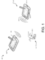
- Fig. 1 is an example arrangement 100 of portable devices as described in present implementations herein.
- the portable devices may utilize antenna arrays with mm-wave waveguide structures to implement a line-of-sight (LOS) wireless communication at WiGig frequency band (i.e., 60GHz).
- the antenna arrays may be utilized further to facilitate position estimation (e.g., azimuth and/or elevation) of a transmitting antenna or device.
- the arrangement 100 illustrates a portable device 102 with multiple antenna arrays 104-2, 104-4 and 104-6; and another portable device 106 with a single antenna array 108.
- the arrangement 100 further illustrates an access point (AP) 110 with antenna arrays 112-2 and 112-4.
- AP access point
- the portable device 102 may include, but is not limited to, a tablet computer, a netbook, a notebook computer, a laptop computer, mobile phone, a cellular phone, a smartphone, a personal digital assistant, a multimedia playback device, a digital music player, a digital video player, a navigational device, a digital camera, and the like.
- the portable device 102 or 104 is considered as a mm-wave portable device due to its feature or capability to operate at WiGig operating frequencies.
- the portable device 102 for example, utilizes the antenna array 104-2 in a LOS wireless communication with the other portable device 106 or the AP 110.
- the portable device 102 utilizes the antenna arrays 104-2 and 104-4 in receiving RF signals from the AP 110.
- each antenna array 104 may be located at an open-end of the mm-wave waveguide structure.
- the antenna arrays 104 are of known orientation to the portable device 102.
- the antenna array 104-2 is optimally disposed on at least one edge and of a certain distance (i.e., equal or less than half wavelength) with respect to the other antenna array 104-4 within the portable device platform.
- the known orientation of the antenna arrays 104 may be utilized in the mathematical operation during the direct estimation of a transmitter position such as the position of the transmitting AP 110 or portable device 106.
- the portable device 102 detects and receives RF signals from the AP 110 and/or the portable device 106.
- the orientation of the antenna arrays 104 may be picked up by a gyro sensor (not shown) within the portable device 102 and the orientation is utilized as a reference variable in the mathematical operation to calculate and distinguish the estimated position of the transmitting AP 110 and/or the portable device 106.
- example arrangement 100 illustrates in a limited manner basic components of mm-wave wireless communications between the portable devices 102 and 106, other components such as battery, one or more processors, SIM card, etc. were not described in order to simplify the embodiments described herein.
- Fig. 2 illustrates an example receiver circuitry 200 that is configured to implement direct estimation of a particular transmitter position.
- the receiver circuitry 200 forms part of the portable device 102 platform and configured to estimate the position of the transmitting AP 110.
- the transmitting AP 110 transmits the RF signals that are received by the portable device 102.
- the RF signals are received through a first antenna array 104-2; phase shifted using Hadamard matrix principle; down-converted into baseband signals; and converted into digital baseband signals with the use of a single A/D converter per antenna array. Thereafter, a mathematical operation is performed to obtain a model of the received RF signal, which includes a first set of "n" snapshots of the received digital baseband signals in the first antenna array 104-2.
- a similar operation is performed for the RF signals received through the second antenna array 104-4 to obtain a second set of "n" snapshots, which is the model of the received digital baseband signals through the second antenna array 104-4.
- a mathematical operation such as the MLE algorithm is performed to calculate the estimated position of the transmitting AP 110.
- the receiver circuitry 200 includes a separate signal processing operation for the first antenna array 104-2, and the second antenna array 104-4.
- the RF signals from the transmitting AP 110 are assumed to be received, but not limited to, by the antenna arrays 104-2 and 104-4.
- the mathematical operations described herein may directly facilitate the estimated position (e.g., horizontal (x), vertical (y), and/or angular (z) orientations) of the transmitting AP 110.
- the RF signals may be detected and received through antennas 202-2, 202-4, ...202-m where "m” may denote the number of elements or antenna in the antenna array 104-2.
- band pass filters (BPFs) 204 and low-noise amplifiers (LNAs) 206 may filter and amplify, respectively, the received RF signals for each antennas 202-2, 202-4.. 202-m.
- each amplified (and filtered) RF signal from the corresponding LNAs 206 is phase shifted by a phase-shifter component 208, which combines the amplified RF signal from each LNA 206 with a phase-shifting or weighting vector 210 to generate phase-shifted (amplified) RF signal.
- W l,m variable is the phase-shifting or weighting vector 210; the " ⁇ " denotes Kronecker matrix product; and " e m " variable is a M x 1 vector whose m th entry is 1 and its remaining entries are 0s.
- a first combiner component 212-2 is configured to combine all phase shifted RF signal outputs from the "m" elements/branch (i.e., antennas 202-2, 202-4, .. 202-m) of the first antenna array 104-2 to generate a combined phase shifted RF signal output. Thereafter, the combined phase shifted RF signal output is down-converted by a converter component 214 into baseband signals.
- the converter component 214 is configured to mix the combined phase shifted RF signal output from the first combiner component 212-2 with a down-converting signal from a local oscillator (LO) 216.
- LO local oscillator
- the LO 216 that supplies the down-converting signal to the converter component 214-2 may be different from the LO that supplies another down-converting signal to another converter component 214-4 as shown by dotted lines.
- the antenna arrays 104-2 and 104-4 as described herein may not necessarily be synchronized to perform the direct estimation of the transmitter position.
- the direct estimation of the transmitter position may be implemented by a single antenna array such as the antenna array 104-2 or antenna array 104-4.
- a magnitude-phase (I/Q) component 218-2 is configured to process in-phase (I) and quadrature (Q) components of the baseband signal before converting the I/Q components into digital baseband signals.
- a single A/D converter component 220. i.e., per antenna array is configured to convert the analog I/Q baseband signal into digital I/Q baseband signals.
- a second combiner component 222-2 may be configured to generate a model of the RF signals received through the antenna array 104-2.
- the model may include, for example, a first set of "n" snapshots of the received RF signal from the first antenna array 104-2. In this example, it is assumed that complex gain of channel paths remains constant and does not change between snapshots.
- an n th snapshot may be defined as: W l ⁇ w l , 1 T w l , 2 T ⁇ w l , M T , y l , n ⁇ y l , 1 n y l , 2 n ⁇ y l , M n , n l , n ⁇ n l , 1 n n l , 2 n ⁇ n l , M n
- the variables " w l " is a phase-shift/weighting vector for all possible phase shifts
- variable " y l,n " is a model of the received signal for all antenna/elements of the antenna array
- the variable "n l,n " is additive Gaussian noise.
- variable " a l (p) " is a receiving array steering vector with function "p" (i.e., position); and the variable " ⁇ l " is an unknown complex gain associated with a first channel tap that is observed by the "l"th array.
- the antenna arrays are co-located, the complex attenuation coefficients are assumed to be correlated.
- the operation and/or process described above for the antenna array 104-2 may be implemented similarly to the second antenna array 104-4.
- the RF signals received through the second antenna array 104-4 may undergo processing at BPFs 228, LNAs 230, phase shifting components 232, a first combiner 212-4, a converter component 214-4, an I/Q component 218, a single A/D 220-4, and finally, in matrix form, a second set of "n" snapshot is derived from an output of a second combiner 222-4.
- the maximization of Eq. 11 may be achieved via 2-dimensional grid search.
- ⁇ and ⁇ the relationship between the angle (i.e., ⁇ and ⁇ ) and position may be defined by Eq. 12 below.
- the maximization of Eq. 16 may be achieved via 3-dimensional grid search over ⁇ x , y, z ⁇ coordinates range.
- a position estimator component 224 may be configured to implement the mathematical algorithm as described above.
- the position estimator may be further implemented as a firmware, software, hardware, or a combination thereof.
- the mathematical algorithm may facilitate an output 226, which is the estimated actual position of the transmitting AP 110.
- Fig. 3 shows an example process chart 300 illustrating an example method for a direct estimation of a transmitter position by a portable device.
- the direct estimation may be based upon the received raw signals from the transmitter and with the use of mathematical operations that may not require an initial estimation of AOA, which is typically used as a basis for estimating the transmitter position.
- AOA initial estimation of AOA
- the order in which the method is described is not intended to be construed as a limitation, and any number of the described method blocks can be combined in any order to implement the method, or alternate method. Additionally, individual blocks may be deleted from the method without departing from the spirit and scope of the subject matter described herein.
- the method may be implemented in any suitable hardware, software, firmware, or a combination thereof, without departing from the scope of the invention.
- receiving RF signals by at least one antenna array is performed.
- a portable device e.g., portable device 102 detects and receives mm-wave wireless signals or RF signals through antenna arrays 104.
- the portable device 102 may include unsynchronized two or more antenna arrays 104 to receive the RF signals.
- the unsynchronized two or more antenna arrays 104 may be connected to different LOs within the portable device 102.
- the estimation of transmitter position as described herein may utilize a single antenna array 104, or multiple antenna arrays 104.
- phase-shifting of the RF signal at each antenna of the at least one antenna array is performed.
- a Hadamard matrix algorithm may facilitate the phase shift for each received RF signal on each antenna of the at least one antenna array 104.
- the phase shifts are of + ⁇ or - ⁇ (i.e., ⁇ 1) phase shifts and are taken from rows of a Hadamard matrix.
- the first combiner component 212-2 may combine phase shifted RF signal from different antenna/elements of the antenna array 104-2. Thereafter, the combined phase shifted RF signals are transformed into baseband signals by converter component 214.
- converting baseband signals into digital signals is performed. For example, a single A/D for each antenna array 104 is utilized to perform analog to digital conversion of the baseband signal, which is derived from the combined phase shifted RF signal output of the first combiner component 212-2.
- performing a mathematical operation to estimate a transmitter position based upon the combined phase shifted RF signals For example, given N snapshots that are collected from each antenna array 104, the cost function is derived to generate the estimated position of the transmitter.
Landscapes
- Engineering & Computer Science (AREA)
- Physics & Mathematics (AREA)
- General Physics & Mathematics (AREA)
- Radar, Positioning & Navigation (AREA)
- Remote Sensing (AREA)
- Computer Networks & Wireless Communication (AREA)
- Signal Processing (AREA)
- Variable-Direction Aerials And Aerial Arrays (AREA)
- Radio Transmission System (AREA)
Abstract
Described herein are architectures, platforms and methods for implementing a direct estimation of a transmitter's position based upon raw radio frequency (RF) signals that are received by a portable device. A mathematical operation such as a maximum-likelihood estimation (MLE) algorithm, which utilizes collected snapshots from the received raw RF signals as variables, is implemented to perform direct estimation.
Description
- An increasing number of wireless communication standards as applied to a portable device and a trend towards ever smaller, slimmer and lighter portable devices may cause design challenges for antennas or antennae (hereinafter referred to as antennas in this document). Antennas represent a category of components that may fundamentally differ from other components in the portable device. For example, the antenna may be configured to efficiently radiate in free space, whereas the other components are more or less isolated from their surroundings.
- Antennas operating at millimeter wave (mm-wave) frequencies - for high data rate short range links - are expected to gain popularity. One example of such system is called wireless WiGig, which operates at 60GHz frequency band and utilizes a waveguide structure for transmission or reception of radio frequency (RF) signals at this operating frequency. Current antenna designs to estimate a wireless transmitter position may require inefficient use of multiple analog-to-digital (A/D) samplers in all antenna channels of an antenna array (i.e., one A/D sampler per antenna channel). As such, there is a need to improve estimation accuracy, especially when weaker transmission signals are involved during transmitter position estimation.
- The detailed description is described with reference to accompanying figures. In the figures, the left-most digit(s) of a reference number identifies the figure in which the reference number first appears. The same numbers are used throughout the drawings to reference like features and components.
-
Fig. 1 is an example arrangement of millimeter-wave (mm-wave) portable devices during a mm-wave wireless communications as described in present implementations herein. -
Fig. 2 is an example receiver circuitry configured to implement direct estimation of a particular transmitter position as described in present implementations herein. -
Fig. 3 is an example process chart illustrating an example method for implementing a direct estimation of a transmitter position by a portable device. - Described herein are architectures, platforms and methods for a direct estimation of a transmitter's position based upon raw radio frequency (RF) signals that are received by a portable device. For example, the direct estimation may be based upon the raw RF signals received by at least one antenna array within the portable device platform. In this example, a mathematical operation such as a maximum-likelihood estimation (MLE) algorithm, which utilizes collected snapshots from the received raw RF signals as variables, is implemented to perform the direct estimation. In such a case, a typical requirement of initially estimating and using an angle-of-arrival (AOA) as a basis for a subsequent estimation of the transmitter position is bypassed.
- As an example implementation described herein, the RF signals are received through antenna(s) or elements of different antenna arrays within a portable device platform. For each antenna in the antenna array, the received RF signal is phase shifted. For example, the phase shifting is taken from a row of a Hadamard matrix.
- With the phase shifted received RF signals at each antenna of the antenna arrays, a combination step is implemented to gather and combine the phase shifted received RF signals into one received RF signal. The received RF signal is thereafter converted into a baseband signal output and the baseband signal output is transformed into digital baseband signal by a single A/D converter per antenna array.
- Subsequently therein, snapshots of the digital baseband signal from each antenna array are taken and the multiple snapshots for all antenna arrays are gathered to obtain "N" snapshots. As described herein, the MLE algorithm utilizes the "N" snapshots to generate a final transmitter position.
-
Fig. 1 is anexample arrangement 100 of portable devices as described in present implementations herein. The portable devices, for example, may utilize antenna arrays with mm-wave waveguide structures to implement a line-of-sight (LOS) wireless communication at WiGig frequency band (i.e., 60GHz). In this example, the antenna arrays may be utilized further to facilitate position estimation (e.g., azimuth and/or elevation) of a transmitting antenna or device. - As shown, the
arrangement 100 illustrates aportable device 102 with multiple antenna arrays 104-2, 104-4 and 104-6; and anotherportable device 106 with asingle antenna array 108. Thearrangement 100 further illustrates an access point (AP) 110 with antenna arrays 112-2 and 112-4. - The
portable device 102 may include, but is not limited to, a tablet computer, a netbook, a notebook computer, a laptop computer, mobile phone, a cellular phone, a smartphone, a personal digital assistant, a multimedia playback device, a digital music player, a digital video player, a navigational device, a digital camera, and the like. - The
portable device 102 or 104 is considered as a mm-wave portable device due to its feature or capability to operate at WiGig operating frequencies. Theportable device 102, for example, utilizes the antenna array 104-2 in a LOS wireless communication with the otherportable device 106 or the AP 110. In another example, theportable device 102 utilizes the antenna arrays 104-2 and 104-4 in receiving RF signals from theAP 110. In these examples, each antenna array 104 may be located at an open-end of the mm-wave waveguide structure. - As described herein, the antenna arrays 104 are of known orientation to the
portable device 102. For example, the antenna array 104-2 is optimally disposed on at least one edge and of a certain distance (i.e., equal or less than half wavelength) with respect to the other antenna array 104-4 within the portable device platform. In this example, the known orientation of the antenna arrays 104 may be utilized in the mathematical operation during the direct estimation of a transmitter position such as the position of the transmittingAP 110 orportable device 106. - For example, the
portable device 102 detects and receives RF signals from theAP 110 and/or theportable device 106. In this example, the orientation of the antenna arrays 104 may be picked up by a gyro sensor (not shown) within theportable device 102 and the orientation is utilized as a reference variable in the mathematical operation to calculate and distinguish the estimated position of the transmittingAP 110 and/or theportable device 106. - Although the
example arrangement 100 illustrates in a limited manner basic components of mm-wave wireless communications between theportable devices -
Fig. 2 illustrates anexample receiver circuitry 200 that is configured to implement direct estimation of a particular transmitter position. Thereceiver circuitry 200, for example, forms part of theportable device 102 platform and configured to estimate the position of the transmittingAP 110. In this example, the transmittingAP 110 transmits the RF signals that are received by theportable device 102. - As a general overview of
Fig. 2 , the RF signals, for example, are received through a first antenna array 104-2; phase shifted using Hadamard matrix principle; down-converted into baseband signals; and converted into digital baseband signals with the use of a single A/D converter per antenna array. Thereafter, a mathematical operation is performed to obtain a model of the received RF signal, which includes a first set of "n" snapshots of the received digital baseband signals in the first antenna array 104-2. - A similar operation (as discussed in the foregoing) is performed for the RF signals received through the second antenna array 104-4 to obtain a second set of "n" snapshots, which is the model of the received digital baseband signals through the second antenna array 104-4. After gathering all of the obtained "n" snapshots from each antenna arrays 104 to obtain a total "N" snapshots, a mathematical operation such as the MLE algorithm is performed to calculate the estimated position of the transmitting
AP 110. - With continuing reference to
Fig. 2 , thereceiver circuitry 200 includes a separate signal processing operation for the first antenna array 104-2, and the second antenna array 104-4. For purposes of illustration, the RF signals from the transmittingAP 110 are assumed to be received, but not limited to, by the antenna arrays 104-2 and 104-4. Based from the received RF signals, the mathematical operations described herein may directly facilitate the estimated position (e.g., horizontal (x), vertical (y), and/or angular (z) orientations) of the transmittingAP 110. - For the antenna array 104-2, the RF signals may be detected and received through antennas 202-2, 202-4, ...202-m where "m" may denote the number of elements or antenna in the antenna array 104-2. With the received RF signals at each of the antennas 202-2, 202-4, ...202-m, band pass filters (BPFs) 204 and low-noise amplifiers (LNAs) 206 may filter and amplify, respectively, the received RF signals for each antennas 202-2, 202-4.. 202-m. Thereafter, each amplified (and filtered) RF signal from the
corresponding LNAs 206 is phase shifted by a phase-shifter component 208, which combines the amplified RF signal from eachLNA 206 with a phase-shifting orweighting vector 210 to generate phase-shifted (amplified) RF signal. - As described herein, the phase-shifting or
weighting vector 210 may include Hadamard matrix entries (i.e., +- 1) defined as:


- where "Wℓ,m" variable is the phase-shifting or
weighting vector 210; the " ⊗" denotes Kronecker matrix product; and "e m" variable is aM x 1 vector whose mth entry is 1 and its remaining entries are 0s. - With the phase shifted RF signal output from each phase-shifting or
weighting vector 210, a first combiner component 212-2 is configured to combine all phase shifted RF signal outputs from the "m" elements/branch (i.e., antennas 202-2, 202-4, .. 202-m) of the first antenna array 104-2 to generate a combined phase shifted RF signal output. Thereafter, the combined phase shifted RF signal output is down-converted by a converter component 214 into baseband signals. For example, the converter component 214 is configured to mix the combined phase shifted RF signal output from the first combiner component 212-2 with a down-converting signal from a local oscillator (LO) 216. - In an implementation, the
LO 216 that supplies the down-converting signal to the converter component 214-2 may be different from the LO that supplies another down-converting signal to another converter component 214-4 as shown by dotted lines. In such a case, the antenna arrays 104-2 and 104-4 as described herein may not necessarily be synchronized to perform the direct estimation of the transmitter position. Furthermore, the direct estimation of the transmitter position may be implemented by a single antenna array such as the antenna array 104-2 or antenna array 104-4. - After obtaining the baseband signal output from the converter component 214, a magnitude-phase (I/Q) component 218-2 is configured to process in-phase (I) and quadrature (Q) components of the baseband signal before converting the I/Q components into digital baseband signals. For example, a single A/D converter component 220. (i.e., per antenna array) is configured to convert the analog I/Q baseband signal into digital I/Q baseband signals.
- As described in present implementations herein, a second combiner component 222-2 may be configured to generate a model of the RF signals received through the antenna array 104-2. The model may include, for example, a first set of "n" snapshots of the received RF signal from the first antenna array 104-2. In this example, it is assumed that complex gain of channel paths remains constant and does not change between snapshots.
- Concatenating all training field samples into a vector, an nth snapshot may be defined as:

- In another form such as in matrix form, the nth antenna array snapshot is given by:

- where the variable " aℓ(p) " is a receiving array steering vector with function "p" (i.e., position); and the variable " βℓ " is an unknown complex gain associated with a first channel tap that is observed by the "ℓ"th array. In this case, since the antenna arrays are co-located, the complex attenuation coefficients are assumed to be correlated.
- The operation and/or process described above for the antenna array 104-2 may be implemented similarly to the second antenna array 104-4. As shown, the RF signals received through the second antenna array 104-4 may undergo processing at
BPFs 228,LNAs 230,phase shifting components 232, a first combiner 212-4, a converter component 214-4, an I/Q component 218, a single A/D 220-4, and finally, in matrix form, a second set of "n" snapshot is derived from an output of a second combiner 222-4. - After gathering all "n" snapshots from the antenna arrays 104-2 and 104-4 to obtain "N" snapshots, the MLE in the presence of Gaussian additive noise is derived. That is, given N snapshots collected from each array, the following cost function is written as:

- Where the following is defined:

where 1 N is a N × 1 vector of 1s. - Using Eq. 3, the cost function Q(p) may be further recast as:

- Using the Kronecker operator properties, the least squares estimate of "βℓ" is given by,

- Since the variable "Wℓ" is a Hadamard matrix, it is noted that

- Furthermore, ∥a ℓ∥2 = 1, therefore it is derived:

- Furthermore still, it is denoted that Πã(ã H ã)-1ã H . and after substituting Eq. (7) back into Eq. 2, it is derived:


- Since ỹ H ỹ is free of θℓ and φℓ, minimizing Eq. 8 is equivalent to maximizing the following cost function:

where Tr{.} denotes the matrix trace operator, and Ṙ is the sample covariance matrix given by:
- As described herein, the MLE of θ and φ may be stated as:


- Furthermore, the maximization of Eq. 11 may be achieved via 2-dimensional grid search.
- With regard to the MLE of p, the relationship between the angle (i.e., θ and φ) and position may be defined by Eq. 12 below.

- Referring back to Eq. (2) to Eq. (7) above, the following is denoted by


- After substituting Eq. 7 back to Eq. 2, the following is derived:

- Since


where Tr{.} denotes the matrix trace operator, an R̂ is the sample covariance matrix given by:
- The MLE of p may be stated as:

- Where
a ℓ (p)Wℓaℓ. As opposed to the maximization of Eq. 11 above where a 2-dimensional grid search is utilized, the maximization of Eq. 16 may be achieved via 3-dimensional grid search over {x, y, z} coordinates range.
- With continuing reference to
Fig. 2 , aposition estimator component 224 may be configured to implement the mathematical algorithm as described above. The position estimator may be further implemented as a firmware, software, hardware, or a combination thereof. The mathematical algorithm may facilitate anoutput 226, which is the estimated actual position of the transmittingAP 110. -
Fig. 3 shows anexample process chart 300 illustrating an example method for a direct estimation of a transmitter position by a portable device. For example, the direct estimation may be based upon the received raw signals from the transmitter and with the use of mathematical operations that may not require an initial estimation of AOA, which is typically used as a basis for estimating the transmitter position. The order in which the method is described is not intended to be construed as a limitation, and any number of the described method blocks can be combined in any order to implement the method, or alternate method. Additionally, individual blocks may be deleted from the method without departing from the spirit and scope of the subject matter described herein. Furthermore, the method may be implemented in any suitable hardware, software, firmware, or a combination thereof, without departing from the scope of the invention. - At
block 302, receiving RF signals by at least one antenna array is performed. For example, a portable device (e.g., portable device 102) detects and receives mm-wave wireless signals or RF signals through antenna arrays 104. - As described herein, the
portable device 102 may include unsynchronized two or more antenna arrays 104 to receive the RF signals. For example, the unsynchronized two or more antenna arrays 104 may be connected to different LOs within theportable device 102. In this example, the estimation of transmitter position as described herein may utilize a single antenna array 104, or multiple antenna arrays 104. - At
block 304, phase-shifting of the RF signal at each antenna of the at least one antenna array is performed. For example, a Hadamard matrix algorithm may facilitate the phase shift for each received RF signal on each antenna of the at least one antenna array 104. The phase shifts are of +π or -π (i.e., ±1) phase shifts and are taken from rows of a Hadamard matrix. - At
block 306, combining the phase shifted RF signals is performed. For example, the first combiner component 212-2 may combine phase shifted RF signal from different antenna/elements of the antenna array 104-2. Thereafter, the combined phase shifted RF signals are transformed into baseband signals by converter component 214. - At
block 308, converting baseband signals into digital signals is performed. For example, a single A/D for each antenna array 104 is utilized to perform analog to digital conversion of the baseband signal, which is derived from the combined phase shifted RF signal output of the first combiner component 212-2. - At
block 310, performing a mathematical operation to estimate a transmitter position based upon the combined phase shifted RF signals. For example, given N snapshots that are collected from each antenna array 104, the cost function is derived to generate the estimated position of the transmitter. - The following examples pertain to further embodiments:
- Example 1 is a method of estimating a transmitter position, the method comprising: receiving radio frequency (RF) signals by at least one antenna array; phase shifting the received RF signal at each element of the least one antenna array; combining the phase shifted RF signals and transforming the combined phase shifted RF signals into baseband signals; converting the baseband signals into digital baseband signals; and generating snapshots of the received digital baseband signals with a maximum likelihood estimation (MLE) operation to generate an estimated transmitter position.
- In example 2, the method as recited in example 1, wherein the phase shifting of the received of the RF signals comprises generating phase shifts from a row of a Hadamard matrix.
- In example 3, the method as recited in example 1, wherein the converting into digital baseband signals comprises using a single analog to digital (A/D) converter per antenna array.
- In example 4, the method as recited in example 1, wherein the generating snapshots comprises generating separate snapshots per antenna array, and gathering the separate snapshots for all antenna arrays.
- In example 5, the method as recited in example 1 further comprising filtering and amplifying the received RF signals prior to the phase shifting.
- In example 6, the method as recited in example 1, wherein the converting into digital baseband signals comprises using different local oscillators per antenna array.
- In example 7, the method as recited in example 6, wherein the antenna array is synchronized separate from any other antenna array.
- In example 8, the method as recited in example 1, wherein the MLE is operation is based on a Gaussian additive noise.
- In example 9, the method as recited in example any of examples 1 to 8, wherein the estimated position comprises an azimuth and an elevation of the transmitter position.
- Example 10 is a device comprising: at least one antenna array configured to receive radio frequency (RF) signals; a phase-shifter component configured to each element of the at least one antenna array, the phase-shifter component is configured to shift phase of the received RF signal at each element of the least one antenna array; a first combiner component configured to combine the phase shifted RF signals; a converter component configured to transform the combined phase shifted RF signals into baseband signals; an analog to digital (A/D) converter component configured to convert the baseband signals into digital baseband signals; anda position estimator component configured to generate snapshots of the received digital baseband signals, with a maximum likelihood estimation (MLE) operation to generate an estimated transmitter position.
- In example 11, the device as recited in example 10, wherein the phase-shifter component is configured to generate phase shifts from a row of a Hadamard matrix.
- In example 12, the device as recited in example 10, wherein the converter component comprises a single analog to digital (A/D) converter per antenna array.
- In example 13, the device as recited in example 10 further comprising a local oscillator configured to supply a down-converting signal to the converter component.
- In example 14, the device as recited in example 13, wherein the antenna array is synchronized separate from any other antenna array.
- In example 15, the device as recited in example any of examples 10 to 14, wherein the position estimator component is configured to calculate the MLE based on a Gaussian additive noise.
- Example 16 is a receiver circuit comprising: at least one antenna array with multiple elements configured to receive radio frequency (RF) signals on each element; a phase-shifter component at each element of the at least one antenna array, the phase-shifter component configured to shift phase of the received RF signal at each element of the least one antenna array; a first combiner component configured to combine the phase shifted RF signals from each element of the at least one antenna array; a converter component configured to transform the combined phase shifted RF signals into baseband signals; an analog to digital (A/D) converter component configured to convert the baseband signals into digital baseband signals; and a position estimator component configured to perform a maximum likelihood estimation (MLE) operation on the received digital baseband signals to generate an estimated transmitter position.
- In example 17, the receiver circuitry as recited in example 16, wherein the phase-shifter component is configured to generate phase shifts from a row of a Hadamard matrix.
- In example 18, the receiver circuitry as recited in example 16 further comprising a local oscillator configured to supply a down-converting signal to the converter component.
- In example 19, the receiver circuitry as recited in example 16 wherein the position estimator component is configured to calculate the MLE based on a Gaussian additive noise.
- In example 20, the receiver circuitry as recited in example any of examples 16 to 19, wherein the converter component comprises a single analog to digital (A/D) converter per antenna array.
Claims (15)
- A method of estimating a transmitter position, the method comprising:receiving radio frequency (RF) signals by at least one antenna array;phase shifting the received RF signal at each element of the least one antenna array;combining the phase shifted RF signals and transforming the combined phase shifted RF signals into baseband signals;converting the baseband signals into digital baseband signals; andgenerating snapshots of the received digital baseband signals with a maximum likelihood estimation (MLE) operation to generate an estimated transmitter position.
- The method as recited in claim 1, wherein the phase shifting of the received of the RF signals comprises generating phase shifts from a row of a Hadamard matrix.
- The method as recited in claim 1, wherein the converting into digital baseband signals comprises using a single analog to digital (A/D) converter per antenna array.
- The method as recited in claim 1, wherein the generating snapshots comprises generating separate snapshots per antenna array, and gathering the separate snapshots for all antenna arrays.
- The method as recited in claim 1 further comprising filtering and amplifying the received RF signals prior to the phase shifting.
- The method as recited in claim 1, wherein the converting into digital baseband signals comprises using different local oscillators per antenna array.
- The method as recited in claim 6, wherein the antenna array is synchronized separate from any other antenna array.
- The method as recited in claim 1, wherein the MLE is operation is based on a Gaussian additive noise.
- The method as recited in claims 1, wherein the estimated position comprises an azimuth and an elevation of the transmitter position.
- A device comprising:at least one antenna array configured to receive radio frequency (RF) signals;a phase-shifter component configured to each element of the at least one antenna array, the phase-shifter component is configured to shift phase of the received RF signal at each element of the least one antenna array;a first combiner component configured to combine the phase shifted RF signals;a converter component configured to transform the combined phase shifted RF signals into baseband signals;an analog to digital (A/D) converter component configured to convert the baseband signals into digital baseband signals; anda position estimator component configured to generate snapshots of the received digital baseband signals, with a maximum likelihood estimation (MLE) operation to generate an estimated transmitter position.
- The device as recited in claim 10, wherein the phase-shifter component is configured to generate phase shifts from a row of a Hadamard matrix.
- The device as recited in claim 10, wherein the converter component comprises a single analog to digital (A/D) converter per antenna array.
- The device as recited in claim 10 further comprising a local oscillator configured to supply a down-converting signal to the converter component.
- The device as recited in claim 13, wherein the antenna array is synchronized separate from any other antenna array.
- The device as recited in claims 13, wherein the position estimator component is configured to calculate the MLE based on a Gaussian additive noise.
Applications Claiming Priority (1)
| Application Number | Priority Date | Filing Date | Title |
|---|---|---|---|
| US14/754,683 US9872136B2 (en) | 2015-06-29 | 2015-06-29 | Method and apparatus for transmitter geo-location in mobile platforms |
Publications (1)
| Publication Number | Publication Date |
|---|---|
| EP3112892A1 true EP3112892A1 (en) | 2017-01-04 |
Family
ID=56087145
Family Applications (1)
| Application Number | Title | Priority Date | Filing Date |
|---|---|---|---|
| EP16171423.3A Withdrawn EP3112892A1 (en) | 2015-06-29 | 2016-05-25 | A method and apparatus for transmitter geo-location in mobile platforms |
Country Status (3)
| Country | Link |
|---|---|
| US (1) | US9872136B2 (en) |
| EP (1) | EP3112892A1 (en) |
| CN (1) | CN106291458B (en) |
Families Citing this family (1)
| Publication number | Priority date | Publication date | Assignee | Title |
|---|---|---|---|---|
| JP7581992B2 (en) * | 2021-03-16 | 2024-11-13 | 富士通株式会社 | Analysis programs, analysis methods, computers and machine learning programs |
Citations (2)
| Publication number | Priority date | Publication date | Assignee | Title |
|---|---|---|---|---|
| US7477192B1 (en) * | 2007-02-22 | 2009-01-13 | L-3 Communications Titan Corporation | Direction finding system and method |
| US20130169471A1 (en) * | 2011-12-28 | 2013-07-04 | Hrl Laboratories, Llc | Coded aperture beam analysis method and apparatus |
Family Cites Families (14)
| Publication number | Priority date | Publication date | Assignee | Title |
|---|---|---|---|---|
| US4578678A (en) * | 1983-11-14 | 1986-03-25 | The United States Of America As Represented By The United States National Aeronautics And Space Administration | High dynamic global positioning system receiver |
| US6615024B1 (en) * | 1998-05-01 | 2003-09-02 | Arraycomm, Inc. | Method and apparatus for determining signatures for calibrating a communication station having an antenna array |
| FI20010079A7 (en) * | 2001-01-12 | 2002-07-13 | Nokia Corp | Positioning method and radio system |
| KR100434336B1 (en) * | 2002-02-21 | 2004-06-04 | 이노에이스(주) | Broadband radio relay apparatus using interference signal rejection of mobile telecommunication system |
| CN1170450C (en) * | 2002-09-13 | 2004-10-06 | 大唐移动通信设备有限公司 | Real-time Calibration Method for Smart Antenna Array |
| US7873326B2 (en) * | 2006-07-11 | 2011-01-18 | Mojix, Inc. | RFID beam forming system |
| US8577305B1 (en) * | 2007-09-21 | 2013-11-05 | Marvell International Ltd. | Circuits and methods for generating oscillating signals |
| US8334809B2 (en) * | 2008-10-22 | 2012-12-18 | Raytheon Company | Active electronically scanned array antenna for satellite communications |
| US8824526B2 (en) * | 2010-02-18 | 2014-09-02 | Intel Mobile Communications GmbH | Apparatus and method for antenna diversity reception |
| SG189297A1 (en) * | 2010-10-21 | 2013-05-31 | Locata Corp | Method and apparatus for forming a remote beam |
| US9535151B2 (en) * | 2011-12-28 | 2017-01-03 | Hrl Laboratories, Llc | Coded aperture beam analysis method and apparatus |
| KR20130127347A (en) * | 2012-05-10 | 2013-11-22 | 삼성전자주식회사 | Method and apparatus for communication on analog and digital hybrid beam-forming |
| US9088330B2 (en) * | 2013-04-24 | 2015-07-21 | Cubic Corporation | Distributed local oscillator generation and synchronization |
| KR101488298B1 (en) * | 2013-11-06 | 2015-01-30 | (주)에어포인트 | Radio repeating apparatus and system, and method thereof |
-
2015
- 2015-06-29 US US14/754,683 patent/US9872136B2/en not_active Expired - Fee Related
-
2016
- 2016-05-25 EP EP16171423.3A patent/EP3112892A1/en not_active Withdrawn
- 2016-06-01 CN CN201610383946.XA patent/CN106291458B/en not_active Expired - Fee Related
Patent Citations (2)
| Publication number | Priority date | Publication date | Assignee | Title |
|---|---|---|---|---|
| US7477192B1 (en) * | 2007-02-22 | 2009-01-13 | L-3 Communications Titan Corporation | Direction finding system and method |
| US20130169471A1 (en) * | 2011-12-28 | 2013-07-04 | Hrl Laboratories, Llc | Coded aperture beam analysis method and apparatus |
Non-Patent Citations (2)
| Title |
|---|
| P. STOICA ET AL: "Maximum likelihood methods for direction-of-arrival estimation", IEEE TRANSACTIONS ON ACOUSTICS, SPEECH AND SIGNAL PROCESSING., vol. 38, no. 7, 6 August 2002 (2002-08-06), USA, pages 1132 - 1143, XP055311055, ISSN: 0096-3518, DOI: 10.1109/29.57542 * |
| XIAOJING HUANG ET AL: "Wideband AoA Estimation and Beamforming with Hybrid Antenna Array", GLOBAL TELECOMMUNICATIONS CONFERENCE (GLOBECOM 2011), 2011 IEEE, IEEE, 5 December 2011 (2011-12-05), pages 1 - 6, XP032118784, ISBN: 978-1-4244-9266-4, DOI: 10.1109/GLOCOM.2011.6133583 * |
Also Published As
| Publication number | Publication date |
|---|---|
| CN106291458A (en) | 2017-01-04 |
| CN106291458B (en) | 2019-05-21 |
| US9872136B2 (en) | 2018-01-16 |
| US20160381498A1 (en) | 2016-12-29 |
Similar Documents
| Publication | Publication Date | Title |
|---|---|---|
| US10620297B2 (en) | Radar methods and apparatus using in phased array communication systems | |
| EP3114782B1 (en) | Analog built-in self test transceiver | |
| JP6685623B2 (en) | Efficient sparse channel estimation based on compressed sensing | |
| US8712356B2 (en) | Apparatus and method for phase synchronization in radio frequency transmitters | |
| US10969457B2 (en) | Receiver-system | |
| US10116396B1 (en) | Millimeter-wave sourceless receiver | |
| Georgiadis et al. | Microwave and millimeter wave circuits and systems: emerging design, technologies and applications | |
| US7885688B2 (en) | Methods and systems for signal selection | |
| US10958295B2 (en) | Complex domain beamforming system and methods relating thereto | |
| Kumar et al. | Improved real time GPS RF data capturing for GNSS SDR applications | |
| EP3112892A1 (en) | A method and apparatus for transmitter geo-location in mobile platforms | |
| US8154451B2 (en) | Adaptive use of polarization as a means of increased wireless channel capacity | |
| RU2631422C1 (en) | Correlation-phase direction-finder | |
| US20060119514A1 (en) | Radio signal direction finder | |
| KR100996430B1 (en) | Frequency hopping signal collection device and method using azimuth information | |
| EP3465952B1 (en) | Method and apparatus for antenna array calibration using on-board receiver | |
| CN210323343U (en) | Ultrashort wave binary channels broadband direction finding system | |
| KR101498615B1 (en) | Apparatus and method for estimating direction of relaying radio signal | |
| US12451916B2 (en) | Transmitting or receiving circularly polarized signals by linearly polarized antennas | |
| Pulipati et al. | Real-time FPGA-Based multi-beam directional sensing of 2.4 GHz ISM RF sources | |
| Park et al. | Implementation and performance analysis of Multi-GNSS signal collection system using single USRP | |
| US20190011568A1 (en) | Device for combining multiple satellite navigation signals, and signal processing device comprising same | |
| Adane et al. | Dual-tracking multi-constellation GNSS front-end for high-performance receiver applications | |
| KR20220064219A (en) | Estimation device of radar direction of arrival based on time division analog to digital converter, and method thereof | |
| JP2013186074A (en) | Receiver |
Legal Events
| Date | Code | Title | Description |
|---|---|---|---|
| PUAI | Public reference made under article 153(3) epc to a published international application that has entered the european phase |
Free format text: ORIGINAL CODE: 0009012 |
|
| 17P | Request for examination filed |
Effective date: 20160525 |
|
| AK | Designated contracting states |
Kind code of ref document: A1 Designated state(s): AL AT BE BG CH CY CZ DE DK EE ES FI FR GB GR HR HU IE IS IT LI LT LU LV MC MK MT NL NO PL PT RO RS SE SI SK SM TR |
|
| AX | Request for extension of the european patent |
Extension state: BA ME |
|
| STAA | Information on the status of an ep patent application or granted ep patent |
Free format text: STATUS: THE APPLICATION HAS BEEN WITHDRAWN |
|
| 18W | Application withdrawn |
Effective date: 20200311 |