EP3112877A1 - Surface current estimation device, surface current estimation system, ocean model estimation device, and risk determination device - Google Patents
Surface current estimation device, surface current estimation system, ocean model estimation device, and risk determination device Download PDFInfo
- Publication number
- EP3112877A1 EP3112877A1 EP15754998.1A EP15754998A EP3112877A1 EP 3112877 A1 EP3112877 A1 EP 3112877A1 EP 15754998 A EP15754998 A EP 15754998A EP 3112877 A1 EP3112877 A1 EP 3112877A1
- Authority
- EP
- European Patent Office
- Prior art keywords
- surface current
- ship
- velocity vector
- estimator
- velocity
- Prior art date
- Legal status (The legal status is an assumption and is not a legal conclusion. Google has not performed a legal analysis and makes no representation as to the accuracy of the status listed.)
- Granted
Links
Images









Classifications
-
- G—PHYSICS
- G01—MEASURING; TESTING
- G01P—MEASURING LINEAR OR ANGULAR SPEED, ACCELERATION, DECELERATION, OR SHOCK; INDICATING PRESENCE, ABSENCE, OR DIRECTION, OF MOVEMENT
- G01P5/00—Measuring speed of fluids, e.g. of air stream; Measuring speed of bodies relative to fluids, e.g. of ship, of aircraft
-
- B—PERFORMING OPERATIONS; TRANSPORTING
- B63—SHIPS OR OTHER WATERBORNE VESSELS; RELATED EQUIPMENT
- B63B—SHIPS OR OTHER WATERBORNE VESSELS; EQUIPMENT FOR SHIPPING
- B63B79/00—Monitoring properties or operating parameters of vessels in operation
- B63B79/10—Monitoring properties or operating parameters of vessels in operation using sensors, e.g. pressure sensors, strain gauges or accelerometers
- B63B79/15—Monitoring properties or operating parameters of vessels in operation using sensors, e.g. pressure sensors, strain gauges or accelerometers for monitoring environmental variables, e.g. wave height or weather data
-
- B—PERFORMING OPERATIONS; TRANSPORTING
- B63—SHIPS OR OTHER WATERBORNE VESSELS; RELATED EQUIPMENT
- B63B—SHIPS OR OTHER WATERBORNE VESSELS; EQUIPMENT FOR SHIPPING
- B63B49/00—Arrangements of nautical instruments or navigational aids
Definitions
- This disclosure relates to a surface current estimating device and a surface current estimating system, which estimate a velocity of a surface current, and to an ocean model estimating apparatus and a dangerousness determining apparatus, which use the device and system, the surface current being a current of sea water in a surface zone of ocean.
- Patent Document 1 As a method of estimating a velocity of a surface current that is a tidal current in a surface zone of ocean, a method disclosed in Patent Document 1 is known, for example. Specifically, in Patent Document 1, a surface current velocity (a velocity of a surface current) is obtained by applying Fourier transform on reception signals obtained by an ocean radar.
- Patent Document 1 JP1999-237477A
- This disclosure is made in view of the above problems and aims to easily calculate a velocity of a surface current.
- the ground velocity is a velocity over a ground surface
- the log velocity is a velocity over water (sea).
- a log velocity estimating device estimates a log velocity vector of a ship at a target location where the ship is located on the sea.
- the log velocity estimating device includes an estimator configured to receive an input of values of information at the target location, and estimate and output, as the log velocity vector of the ship, a value corresponding to one of conditions, the information being a rotational speed of a propeller of the ship and information of a wind direction and a wind speed which causes an influence on the ship, each of the conditions defined by a combination of the received values.
- an acoustic speed log is used in a case of measuring a log velocity of a first ship.
- a large-scale installation work such as forming a hole in a bottom of the first ship, is required to install the speed log on the first ship.
- the log velocity estimating device for solving the above problems and aims to easily estimate a log velocity vector without requiring the large-scale installation work on the ship.
- the log velocity of the ship can be obtained based on the rotational speed of the propeller of the ship and the information of the wind direction and the wind speed which can be obtained comparatively easily.
- the log velocity vector can easily be estimated without requiring the large-scale installation work on the ship.
- the estimator may be configured using a neural network.
- the estimator which outputs the log velocity vector can suitably be configured.
- the log velocity estimating device may further include a propeller speed detector configured to detect the rotational speed of the propeller, and a vane anemometer equipped in the ship.
- the estimator may receive the rotational speed of the propeller detected by the propeller speed detector, and the information of the wind direction and the wind speed measured by the vane anemometer. Since many of general ships are equipped with such a propeller speed detector and a vane anemometer, by using them, the log velocity vector can be estimated without equipping the ship with an additional instrument to detect the log velocity vector.
- a velocity of a surface current can easily be calculated.
- a surface current estimating device 1 is described with reference to the drawings.
- the surface current estimating device 1 according to this embodiment of this disclosure is equipped in a first ship (ship).
- the surface current estimating device 1 estimates a direction and magnitude of a surface current at a position of the first ship, in other words, a velocity vector of the surface current at the first ship position.
- the surface current estimating device 1 automatically obtains particular parameters (in this embodiment, a rotational speed of a propeller of the first ship, a true wind speed in a bow direction, and a true wind speed in a starboard direction) at every particular timing, and calculates a surface current velocity (surface current velocity vector) at the first ship position for every condition defined by a combination of values of the respective parameters.
- the surface current of this embodiment is a current within a depth range that is about a range from a sea surface to a bottom of the first ship.
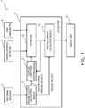
- Fig. 1 is a block diagram illustrating a configuration of the surface current estimating device 1 according to this embodiment of this disclosure.
- the surface current estimating device 1 includes a GPS signal receiver 2, a propeller speed detector 3, a vane anemometer 4, a calculator 10, and a display unit 5.
- the GPS signal receiver 2 is provided as a GNSS signal receiver configured to receive GPS signals as navigation signals (GNSS signals) which are transmitted from navigation satellites (not illustrated).
- the GPS signal receiver 2 includes a GPS antenna, for example.
- the GPS signals received by the GPS signal receiver 2 i.e., positional information of the first ship
- the GPS signals received by the GPS signal receiver 2 is notified to the calculator 10 along with a received time point of the GPS signals.
- the GPS signal receiver 2 is used as the GNSS signal receiver; however, without limiting to this, a receiver used in another GNSS system may be used.
- GNSS is an abbreviation of Global Navigation Satellite Systems. This GNSS is a collective name for "GPS” administrated by the United States of America, “GALILEO” administrated by the European Union, “GLONASS” administrated by Russia, etc.
- the propeller speed detector 3 detects a rotational speed per unit time of the propeller configured to produce a thrust of the first ship, and includes a sensor capable of detecting a rotational speed, for example. The rotational speed detected by the propeller speed detector 3 is notified to the calculator 10.
- the vane anemometer 4 measures, as information of a wind direction and speed, the true wind speed in the bow direction and the true wind speed in the starboard direction.
- the vane anemometer 4 is disposed in the first ship where the surface current estimating device 1 according to this embodiment is equipped, at a location with no obstacle in its surrounding which blocks a wind.
- the true wind speed in the bow direction and the true wind speed in the starboard direction measured by the vane anemometer 4 are notified to the calculator 10.
- the calculator 10 estimates a surface current at the first ship position (target location) at every particular timing, based on the various information notified by the GPS signal receiver 2, the propeller speed detector 3, and the vane anemometer 4.
- the calculator 10 includes a ground velocity calculating module 11, an estimator 12, a surface current calculating module 13, and a coupling coefficient updating module 14.
- the ground velocity calculating module 11 calculates a ground velocity (ground velocity vector) of the first ship based on the positional information of the first ship and the acquired time point of the first ship positional information, which are notified from the GPS signal receiver 2. Specifically, the ground velocity calculating module 11 calculates the ground velocity of the first ship based on first ship positions of at least two timings and acquired time points of the positional information of the respective first ship positions. The ground velocity calculating module 11 notifies the ground speed calculated as above, to the surface current calculating module 13 and the coupling coefficient updating module 14.
- the estimator 12 is configured to estimate a log velocity of the first ship.
- the estimator 12 receives the rotational speed of the propeller of the first ship, which is detected by the propeller speed detector 3, and the true wind speed in the bow direction and the true wind speed in the starboard direction, which are measured by the vane anemometer.
- the estimator 12 outputs to the surface current calculating module 13 a value corresponding to a condition defined by a combination of these input values (a condition defined by a combination of a certain rotational speed, a certain true wind speed in the bow direction, and a certain true wind speed in the starboard direction) as the log velocity (log velocity vector, which is a log velocity in the bow direction and a log velocity in the starboard direction in this embodiment).
- Fig. 2 is a schematic view illustrating one example of a configuration of the estimator 12.
- the estimator 12 is configured using a commonly-known neural network.
- the estimator 12 includes a plurality of input units U IN_1 , U IN_2 and U IN_3 structuring an input layer, a plurality of middle units U MID_1 , U MID_2 and U MID_3 structuring a hidden layer, and a plurality of output units U OUT_1 and U OUT_2 structuring an output layer.
- the configuration of the estimator 12 illustrated in Fig. 2 is merely an example, and the number of units in each layer, the number of hidden layers are not limited to those illustrated in Fig. 2 .
- each of those input values is multiplied by a coupling coefficient W I,M and outputted to the middle units U MID_1 , U MID_2 and U MID_3 of the hidden layer.
- Each of the middle units U MID_1 , U MID_2 and U MID_3 of the hidden layer adds up the inputted values to obtain a total, multiplies by a coupling coefficient W M,O a value obtained based on the total value, and outputs it to the output units U OUT_1 and U OUT_2 .
- Each of the output units U OUT_1 and U OUT_2 adds up the inputted values to obtain a total, and outputs, as an output value, a value obtained based on the total value, to the surface current calculating module 13 and the coupling coefficient updating module 14.
- the values inputted into the estimator 12 are not necessarily the values of the parameter themselves, such as the rotational speed of the propeller, etc., and they may be numerical values which are in a one-to-one relationship with those parameters, respectively (e.g., a voltage value which changes in proportion to the rotational speed), etc.
- a suitable initial value is set for each coupling coefficient W.
- the coupling coefficient W is updated by the coupling coefficient updating module 14 as needed.
- the coupling coefficient W is updated by the coupling coefficient updating module 14 to reduce an error of each output value from the estimator 12 with respect to the ground velocity (teaching signal) calculated by the ground velocity calculating module 11.
- the output value from the estimator 12 although described later in detail, is converged to the log velocity of the first ship every time the coupling coefficient W is updated.
- the surface current calculating module 13 calculates a surface current velocity (surface current velocity vector) that is a velocity of a surface current, based on the output values as the log velocity outputted from the estimator 12 and the ground velocity calculated by the ground velocity calculating module 11. Specifically, the surface current calculating module 13 calculates the surface current velocity by subtracting the log velocity from the ground velocity.
- Fig. 3 is a vector diagram illustrating a relationship among the ground velocity vector V G , the log velocity vector V W , and the surface current velocity vector V T .
- the ground velocity V G is a velocity over a ground surface
- the log velocity V W is a velocity over a water surface (sea surface).
- the surface current is a water current in a surface zone of the sea. Therefore, the relationship among the ground velocity vector V G , the log velocity vector V W , and the surface current velocity vector V T can be expressed as illustrated in Fig. 3 .
- the surface current calculating module 13 subtracts the log velocity V W from the ground velocity V G as described above to calculate the surface current velocity V T .
- the coupling coefficient updating module 14 updates each coupling coefficient W of the estimator 12 to reduce the error of each output value from the estimator 12 with respect to the ground velocity (teaching signal) calculated by the ground velocity calculating module 11.
- the coupling coefficient updating module 14 updates the coupling coefficient W by using a backpropagation method, for example.
- the display unit 5 displays the direction and magnitude of the surface current calculated by the surface current calculating module 13. Thus, a user can learn the velocity of the surface current at the first ship position.
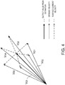
- Fig. 4 is a view illustrating how each output value from the estimator 12 converges to the log velocity every time the coupling coefficient W of the estimator 12 is updated.
- each coupling coefficient W stored in the estimator 12 is updated by the coupling coefficient updating module 14 to reduce the error of the output value, which is outputted from the estimator 12 as needed, with respect to the ground velocity as the teaching signal calculated as needed.
- the surface current varies in magnitude and direction depending on a marine area, time, a meteorological condition, etc.
- the ground velocity is considered to contain components of surface current velocities of various magnitudes and directions. Therefore, by averaging these components (averaging V G1 to V G6 in the case of Fig. 4 ), the surface current velocity components cancel out each other and the log velocity component remain.
- the coupling coefficient W of the estimator 12 is updated to reduce the error of the output value of the estimator 12 with respect to the ground velocity, an influence of the surface current velocity components contained in the ground velocity gradually becomes smaller; therefore, the output value of the estimator 12 converges to the log velocity.
- the output value from the estimator 12 can be estimated as the log velocity.
- the rotational speed is detected by the propeller speed detector 3, and the true wind speed in the bow direction and the true wind speed in the starboard direction are measured by the vane anemometer 4, and these information are outputted to the estimator 12 as needed.
- the estimator 12 generates the output value based on these information by using the coupling coefficient W updated as needed during travel of the first ship.
- the propeller speed detector 3, the vane anemometer 4, and the estimator 12 of this embodiment constitute a log velocity estimating device configured to estimate the log velocity.
- this log velocity estimating device may include the GPS signal receiver 2, the ground velocity calculating module 11, and the coupling coefficient updating module 14. By displaying on the display unit 5 the log velocity estimated by this log velocity estimating device (the output value of the estimator 12), the log velocity can even be notified to the user.
- the propeller speed detector, the vane anemometer, and the estimator of respective modifications described below may also be used as a log velocity estimating device configured to estimate a log velocity.
- the surface current is calculated based on the ground velocity calculated by the ground velocity calculating module 11 and the log velocity estimated by the estimator 12.
- the surface current near the sea surface which causes a comparatively large influence on a movement of the ship can be estimated comparatively easily.
- the velocity of the surface current can easily be calculated.
- the estimator 12 is configured by using the neural network.
- the estimator 12 capable of outputting the log velocity can suitably be configured.
- the estimator 12 is updated to reduce the error of each output value of the estimator 12 with respect to the ground velocity calculated by the ground velocity calculating module 11.
- the estimator 12 provided with the learning function can be configured. Additionally, with the surface current estimating device 1, since a large amount of data required for estimating an accurate log velocity can be accumulated during the travel, a work of preparing learning data (data of a ground velocity under a certain condition) in advance can be omitted.
- the estimator 12 since the estimator 12 is updated using the real-time data acquired while traveling, for example, a local surface current at the first ship position, which cannot be obtained from tidal current information distributed from an official organization, can be obtained.
- the estimator 12 since the estimator 12 is updated using the real-time data described above, the estimator 12 is updated according to a condition of the ship (aged deterioration, fouling etc.) at a current time point. Thus, regardless of the ship condition, the surface current can accurately be estimated.
- the coupling coefficient W stored in the estimator 12 is updated to reduce the error of the output value of the estimator 12 with respect to the ground velocity calculated by the ground velocity calculating module 11.
- the estimator 12 can suitably be updated.
- the surface current estimating device 1 by subtracting the log velocity from the ground velocity, the surface current velocity is calculated.
- the surface current velocity can be calculated more easily.
- the ground velocity can accurately be calculated. Additionally, since many of general ships are equipped with a GPS antenna, the ground velocity can be calculated without introducing an additional device etc.
- the estimator 12 estimates the log velocity in a condition defined by a combination of the respective values of the rotational speed of the propeller of the ship, the true wind speed in the bow direction, and the true wind speed in the starboard direction, which are the parameters which cause a great influence on the log velocity of the ship.
- the log velocity can efficiently be estimated. Additionally, since these parameters can be measured comparatively easily, the log velocity can easily be estimated.
- the rotational speed of the propeller, the true wind speed in the bow direction, and the true wind speed in the starboard direction are detected by the propeller speed detector 3 and the vane anemometer 4 equipped in the first ship. Since many of general ships are equipped with such a detector 3 and a vane anemometer 4, the surface current velocity can be estimated without equipping an additional sensor etc.
- the surface current estimating device 1 is equipped in the first ship.
- the surface current velocity near the first ship can be estimated.
- the surface current estimating device 1a outputs, as a log velocity, an output value by an estimator 12a of which a coupling coefficient W is determined based on many learning data acquired in advance (data of a ground velocity under a certain condition). Also with such a configuration, similar to the above embodiment, the surface current can easily be calculated.
- Fig. 7 is a view illustrating in detail the estimator 12b illustrated in Fig. 6 .
- the memory 15 stores a matrix table as illustrated in Fig. 7 .
- This table stores ground velocities calculated under respective conditions (corresponding to respective cells of the table). Each condition is defined by a combination of a value of a wind direction and speed (X1, X2, X3, ...) and a value of a rotational speed of a propeller (R1, R2, R3, ).
- a single value of a ground velocity is indicated with a single circular mark.
- the memory 15 stores, for example, five values of ground velocity calculated when the value of the wind direction and speed is X1 and the value of the rotational speed is R1.
- the estimator 12b receives the rotational speed detected by the propeller speed detector 3 (e.g., R2) and the wind direction and speed measured by the vane anemometer 4 (e.g., X3), the estimator 12b calculates an average value of the ground velocities contained in the cell where the rotational speed is R2 and the wind direction and speed is X3 (eleven values in the case of Fig. 7 ). Further, the estimator 12b outputs the average value as an output value.
- the propeller speed detector 3 e.g., R2
- the vane anemometer 4 e.g., X3
- the updating module 16 updates the table stored in the memory 15, by using a ground velocity calculated at a timing at which a rotational speed and a wind direction and speed inputted into the estimator 12b are detected. Specifically, the ground velocity calculated at a particular rotational speed (e.g., R3) and a particular wind direction and speed (e.g., X2) is added to a cell defined by R3 and X2. By performing this operation as needed, learning data is accumulated even while traveling, and a log velocity can be estimated more accurately. In other words, the estimator 12b according to this modification also has a learning function. As a result, a surface current velocity can be calculated more accurately.
- a particular rotational speed e.g., R3
- a particular wind direction and speed e.g., X2
- a surface current estimating device lc which does not have the learning function (see Fig. 8 ) can be configured.
- a plurality of leaning data acquired in advance (each data corresponds to a single circular mark in Fig. 7 ) needs to be stored in the memory 15.
- the parameters which are inputted into the estimator 12d may include information of a wave, a roll angle of the ship, a pitch angle of the ship, an amount of heave of the ship, information of a hydrographic condition, information of a meteorological phenomenon, positional information, etc.
- the parameters which are inputted into the estimator 12d may include information of a wave, a roll angle of the ship, a pitch angle of the ship, an amount of heave of the ship, information of a hydrographic condition, information of a meteorological phenomenon, positional information, etc.
- An estimator 12e is configured using a neural network and such that a coupling coefficient is updated as needed by so-called supervised learning.
- a coupling coefficient is updated as needed by so-called supervised learning.
- an error between an output value from the estimator 12e and a teaching signal (ground velocity) is calculated.
- the surface current estimating device 1e updates the coupling coefficient W while propagating the error as a learning signal, from a unit on an output layer side to a unit on an input layer side.
- a correction amount of the coupling coefficient is given by the following Equation 1.
- ⁇ W i , j n , n ⁇ 1 t ⁇ ⁇ i n X j n ⁇ 1 + ⁇ W i , j n , n ⁇ 1 t ⁇ 1
- Equation 1 ⁇ W i,j n,n-1 (t) is a correction amount on a weight of coupling between a unit j of an (n-1)th layer and a unit i of an n-th layer, ⁇ is a learning coefficient, ⁇ i n is a learning signal to be returned back to each unit of the (n-1)th layer from the unit i of the n-th layer, X j n-1 is an output value of the unit j of the (n-1)th layer, ⁇ is a stabilizing coefficient, ⁇ W i,j n,n-1 (t-1) is a previous correction amount.
- the (n-1)th layer is one layer on the input side of the n-th layer.
- Fig. 11 is a block diagram illustrating a configuration of the learning coefficient setting processor 20.
- the learning coefficient setting processor 20 sets the learning coefficient in Equation 1 as needed.
- the learning coefficient setting processor 20 has a memory 21, an SOM updating module 22, a counting module 23, a learning coefficient calculating module 24, and a learning coefficient setting module 25.
- Fig. 12 is a view schematically illustrating a table stored in the memory 21, and a self-organizing map SOM stored in association with each cell of the table.
- the memory 21 stores a table sectioned for every particular propeller rotational speed and every particular wind speed and direction in a grid pattern.
- Each cell of this table stores a corresponding self-organizing map SOM.
- Each self-organizing map SOM of this modification is a two-dimensional SOM formed with an nxn number of units.
- Each unit stores a reference vector of the same dimension as that of an input vector. In an initial state (a state where the learning is not performed), a suitable reference vector is set into the unit.
- the SOM updating module 22 updates the SOM according to the input vector (a vector formed based on a rotational speed of a propeller, a wind direction and speed, a ground velocity, etc. which are inputted at every particular timing). Specifically, the SOM updating module 22 updates as below, the SOM stored in the cell including the inputted rotational speed and the inputted wind direction and speed.
- the input vector a vector formed based on a rotational speed of a propeller, a wind direction and speed, a ground velocity, etc. which are inputted at every particular timing.
- the SOM updating module 22 updates a reference vector stored in the winner unit and reference vectors stored in units around the winner unit, based on the following Equation 2.
- m i t + 1 m i t + h i t x t ⁇ m i t
- m i is the reference vector
- x(t) is the input vector
- h i is a neighborhood function expressed by c ⁇ exp(-dis 2 / ⁇ 2 ).
- c is a learning rate coefficient
- dis lx-m c l.
- m c is a reference vector that minimizes a Euclidean distance from x(t).
- the SOM updating module 22 updates as needed the self-organizing map SOM by the input vector inputted as needed, by using the Equation 2 described above.
- the counting module 23 counts the number of units having a reference vector of which difference (Euclidean distance) from the input vector becomes a certain threshold or below.
- the learning coefficient calculating module 24 calculates an inverse of the value counted by the counting module 23, to be the learning coefficient. Specifically, when the count value is high (when the number of similar input data is large), the learning coefficient becomes low, and when the count value is low (when the number of similar input data is small), the learning coefficient becomes high.
- the learning coefficient setting module 25 notifies to the estimator 12e the value calculated by the learning coefficient calculating module 24, and sets it to be the learning coefficient ⁇ in Equation 1.
- the estimator 12e updates the coupling coefficient based on Equation 1 by using the learning coefficient ⁇ , and then calculates a log velocity vector based on the updated coupling coefficient.
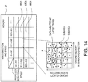
- Fig. 14 is a view illustrating a table stored in the memory 27, and learning data stored in association with each cell (each area) of the table.
- the memory 27 stores a table sectioned for every particular propeller rotational speed and every particular wind speed and direction in a grid pattern.
- the learning data stored in each area is mapped corresponding to the ground velocity of each learning data.
- each learning data is mapped corresponding to the ground velocity.
- the learning coefficient calculating module 28 sets, as the learning coefficient, a value that is obtained by normalizing an inverse of a value calculated by dividing the number of learning data (four in the case of Fig. 14 ) stored in a subarea which includes learning data inputted at a latest timing, by the number of learning data stored in a subarea with a largest number of learning data (ten in a subarea A in the case of Fig. 14 ) among all the subareas of the area having the subarea which includes the learning data inputted at the latest timing.
- the learning coefficient setting module 29 notifies to an estimator the learning coefficient set by the learning coefficient calculating module 28 and sets it to be the learning coefficient ⁇ in Equation 1. Also with such a configuration, the learning coefficient can suitably be set.
- the second ship information receiver 17 receives positional information of a second ship traveling on the sea, information of a surface current velocity at a location of the second ship, etc. from the second ship.
- the second ship information receiver 17 includes an antenna, for example.
- the second ship information receiver 17 receives, from the second ship as needed, surface current velocity information at each location which the second ship traveling on the sea has passed.
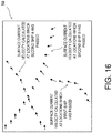
- Fig. 16 is a view illustrating one example of a distribution view of surface current velocities in a wide area, displayed in a display unit 5a of this modification.
- the display unit 5a of this modification displays surface current velocities calculated at locations which second ships have passed in a particular marine area.
- the direction of the arrow displayed on the display screen indicates a direction of the surface current
- the size of the arrow indicates a velocity of the surface current.
- the surface current estimating device 1f As above, according to the surface current estimating device 1f according to this modification, not only the surface current velocity near the first ship position, but also surface current velocities at locations which the first ship has not passed can be obtained. Further, by obtaining the wide area surface current distribution as above, a surface current at a location which is expected that the first ship will pass can be obtained, and the surface current can be utilized as effective information for estimating a time of arrival to a target location and calculating a fuel consumption.
- a second ship information receiver 17a acquires a rotational speed of a propeller, wind direction and speed information, positional information, etc. of the second ship as needed. Further, the second ship calculating module 18 calculates a surface current velocity at a location which the second ship has passed, based on these information. The thus calculated surface current velocity vector at the location which the second ship has passed is displayed on the display unit 5a along with a surface current velocity vector at a location which the first ship has passed (see Fig. 16 ).
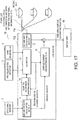
- the transmitter 19a transmits various data detected by the GPS signal receiver 2, the propeller speed detector 3, and the vane anemometer 4, to the data center 30 via antennas.
- a surface current velocity is calculated similarly to the case of the above embodiment.
- the calculator 10h calculates surface current velocities at respective locations which the first ship has passed, and stores them in a database unit 31.
- the receiver 19b receives the surface current velocity data stored in the database unit 31. This data is displayed on a display unit 5.
- a calculator with a comparatively high calculation load can be provided at a different location from the first ship.
- the surface current velocity at the first ship position can be estimated.
- Fig. 20 is a schematic view illustrating complement of the learning data. Since a ship has a substantially laterally symmetrical shape, wind force characteristics (a traveling speed of the ship caused by the wind direction and speed) are estimated to be laterally symmetric. Specifically, for example, between a case where a ship traveling under a certain condition receives a wind from the port quarter at an angle of 45 degrees and a case where the ship receives a wind from the starboard quarter at an angle of 45 degrees (wind speeds are the same), the traveling directions are estimated to be laterally symmetric. Therefore, with reference to Fig.
- the data may be complemented as follows based on the learning data. Specifically, as learning data for when the propeller rotational speed and the wind speed are the same as the learning data of the above case and the wind direction is on the starboard quarter at an angle of 45 degrees, a laterally inverted vector V' G may be complemented.
- a laterally inverted vector V' G may be complemented.
- the ocean model estimating apparatus 35 includes, in addition to the surface current estimating device described above, a second estimator 36 and a coupling coefficient updating module 37.
- the second estimator 36 is configured using a neural network. Further, the second estimator 36 is configured to output, as an output value, a surface current velocity according to inputted positional information and the hydrographic condition and meteorological phenomenon information.
- the hydrographic condition include a height of tide, atmospheric pressure, and a seawater temperature.
- the coupling coefficient updating module 37 compares the surface current velocity calculated by the surface current calculating module 13 with the output value estimated by the second estimator 36, and updates a coupling coefficient of the second estimator 36 to reduce an error therebetween.
- the location-specific surface current velocity according to the hydrographic condition and the meteorological phenomenon can be obtained. Further, by calculating the location-specific surface current velocity at each location on the sea and accumulating them as data, for example, an ocean model for over the world can be structured.
- the dangerousness determining apparatus 40 includes, in addition to the surface current estimating device described above, a spectral resolution module 41 and a dangerousness determining module 42.
- the ground velocity calculating module 11 calculates a ground velocity in three axial directions (directions in a horizontal plane and a vertical direction), and the estimator 12 calculates a log velocity in the three axial directions.
- the surface current calculating module 13 calculates a surface current velocity containing a wave component.
- the spectral resolution module 41 resolves the surface current velocity containing the wave component, which is calculated by the surface current calculating module 13, into a DC component (direct current component) and an AC component (alternate current component).
- the spectral resolution module 41 outputs these components to the dangerousness determining module 42.
- the dangerousness determining module 42 determines the respective output values from the spectral resolution module 41 comprehensively to determine the dangerousness of the wave relative to the first ship. Specifically, for example, the dangerousness determining module 42 determines that the dangerousness is low if values of the DC and AC components are comparatively low, and determines that the dangerousness is high if the values of the DC and AC components are comparatively high. The determination result is outputted to a display unit 5b.
- a dangerousness of a wave relative to the first ship can be obtained based on a sea surface condition obtained using the GPS signal receiver 2 etc. which are equipped in a general ship.
- the dangerousness may be determined by further referring to roll (sway in left-and-right directions with respect to front-and-rear directions of the ship), pitch (sway in the front-and-rear directions with respect to the left-and-right directions of the ship), etc.
Landscapes
- Engineering & Computer Science (AREA)
- Aviation & Aerospace Engineering (AREA)
- Physics & Mathematics (AREA)
- General Physics & Mathematics (AREA)
- Life Sciences & Earth Sciences (AREA)
- Atmospheric Sciences (AREA)
- Environmental & Geological Engineering (AREA)
- Chemical & Material Sciences (AREA)
- Combustion & Propulsion (AREA)
- Mechanical Engineering (AREA)
- Ocean & Marine Engineering (AREA)
- Indicating Or Recording The Presence, Absence, Or Direction Of Movement (AREA)
Abstract
Description
- This disclosure relates to a surface current estimating device and a surface current estimating system, which estimate a velocity of a surface current, and to an ocean model estimating apparatus and a dangerousness determining apparatus, which use the device and system, the surface current being a current of sea water in a surface zone of ocean.
- Conventionally, as a method of estimating a velocity of a surface current that is a tidal current in a surface zone of ocean, a method disclosed in
Patent Document 1 is known, for example. Specifically, inPatent Document 1, a surface current velocity (a velocity of a surface current) is obtained by applying Fourier transform on reception signals obtained by an ocean radar. - Further, as another method of estimating the velocity of the surface current, it is generally known to use instruments, such as an ultrasonic current meter.
- Patent Document 1:
JP1999-237477A - Meanwhile, with the method disclosed in
Patent Document 1, a calculation load for obtaining a spatial distribution of a tidal current is comparatively high and the calculation of the surface current requires comparatively long time. - Whereas, when measuring the surface current with the ultrasonic current meter, a current of a layer below the ultrasonic current meter which is in a state attached to a bottom of a ship is measured. In other words, a current of a shallow layer which causes comparatively large influence on a movement of the ship (a section from a sea surface to the bottom of the ship) cannot be measured.
- This disclosure is made in view of the above problems and aims to easily calculate a velocity of a surface current.
-
- (1) For solving the above problems, a surface current estimating device according to one aspect of this disclosure estimates a surface current velocity vector that is a velocity vector of a surface current at a target location where a ship is located on the sea. The surface current estimating device includes a ground velocity calculating module configured to calculate a ground velocity vector of the ship at the target location, an estimator configured to receive an input of one or more values of at least one parameter at the target location, and estimate and output, as a log velocity vector of the ship, a value corresponding to one of conditions, the at least one parameter causing an influence on the log velocity vector of the ship, each of the conditions defined by a combination of the received values, and a surface current calculating module configured to calculate the surface current velocity vector of the target location, based on the output value as the log velocity vector estimated by the estimator and the ground velocity vector calculated by the ground velocity calculating module.
- Here, the ground velocity is a velocity over a ground surface, and the log velocity is a velocity over water (sea).
- (2) The estimator may be configured either using a neural network or to output, as the output value, an average value of ground velocity vectors calculated by the ground velocity calculating module to correspond to the one of the conditions.
- (3) The surface current estimating device may further include an updating module configured to compare the output value from the estimator with the ground velocity vector calculated by the ground velocity calculating module, and update the estimator to reduce an error between the output value and the ground velocity vector.
- (4) Further, the estimator may be configured using a neural network and may have at least one input unit configured to receive a value corresponding to one of the at least one parameter and an output unit configured to output the output value that is the log velocity vector. A value to be outputted from the input unit of the neural network may be multiplied by a coupling coefficient and then transmitted to the output unit. The updating module may compare the output value with the ground velocity vector that is a teaching signal, and update the coupling coefficient to reduce an error between the output value and the teaching signal.
- (5) The surface current calculating module may calculate the surface current velocity vector by subtracting the log velocity vector estimated by the estimator from the ground velocity vector calculated by the ground velocity calculating module.
- (6) The surface current estimating device may further include a GNSS signal receiver equipped in the ship and configured to receive GNSS signals. The ground velocity calculating module may calculate the ground velocity vector based on the GNSS signals received by the GNSS signal receiver and time points at which the GNSS signals are received.
- (7) The at least one parameter may include one of a rotational speed of a propeller of the ship, information of a wind direction and a wind speed, a rudder angle of the ship, a draft of the ship, information of a wave, a roll angle of the ship, a pitch angle of the ship, an amount of heave of the ship, information of a hydrographic condition, information of a meteorological phenomenon, and positional information.
- (8) Moreover, the surface current estimating device may further include a propeller speed detector configured to detect the rotational speed of the propeller, and a vane anemometer equipped in the ship. The estimator may receive at least the rotational speed of the propeller detected by the propeller speed detector, and the information of the wind direction and the wind speed measured by the vane anemometer.
- (9) The surface current estimating device may be equipped in a first ship that is the ship.
- (10) For solving the above problems, a surface current estimating system according to another aspect of this disclosure includes a calculator having the ground velocity calculating module, the estimator, and the surface current calculating module of any one of the surface current estimating devices described above, the calculator equipped at a location different from that of a first ship that is the ship, a transmitter equipped in the first ship and configured to transmit to the calculator the one or more values of the at least one parameter that causes the influence on the log velocity vector of the first ship, and a receiver equipped in the first ship and configured to receive the surface current velocity vector of the target location, the surface current velocity vector calculated by the calculator.
- (11) The calculator may also calculate a surface current velocity vector of a location where a second ship is located, based on one or more values of the at least one parameter regarding the second ship. The receiver may also receive the surface current velocity vector of the location where the second ship is located, the surface current velocity vector calculated by the calculator.
- (12) Moreover, the surface current estimating system may further include a display unit configured to display a desired area on the sea and capable of displaying the surface current velocity vector of the target location of the first ship within the desired area, and the surface current velocity vector of the location where the second ship is located within the desired area.
- (13) For solving the above problems, an ocean model estimating apparatus according to another aspect of this disclosure includes any one of the surface current estimating devices described above and any one of the surface current estimating systems described above. The estimator of the one of the surface current estimating device and the surface current estimating system is provided as a first estimator. The ocean model estimating apparatus further includes a second estimator configured using a neural network and configured to receive positional information of a first ship, information of a current hydrographic condition, and information of a meteorological phenomenon, output, as an output value, a value corresponding to one of conditions, and be updated to reduce an error between a surface current velocity vector and the output value, each of the conditions defined by a combination of the received information, the surface current velocity vector calculated as a teaching signal by the one of the surface current estimating device and the surface current estimating system.
- (14) For solving the above problems, a dangerousness determining apparatus according to another aspect of this disclosure includes any one of the surface current estimating devices described above and any one of the surface current estimating systems described above, and a determining module configured to determine a dangerousness of a wave relative to a first ship based on at least the surface current velocity vector estimated by the one of the surface current estimating device and the surface current estimating system.
- Further, a log velocity estimating device according to another aspect estimates a log velocity vector of a ship at a target location where the ship is located on the sea. The log velocity estimating device includes an estimator configured to receive an input of values of information at the target location, and estimate and output, as the log velocity vector of the ship, a value corresponding to one of conditions, the information being a rotational speed of a propeller of the ship and information of a wind direction and a wind speed which causes an influence on the ship, each of the conditions defined by a combination of the received values.
- Generally, in a case of measuring a log velocity of a first ship, for example, an acoustic speed log is used. However in such a case, a large-scale installation work, such as forming a hole in a bottom of the first ship, is required to install the speed log on the first ship.
- The log velocity estimating device according to the other aspect described above is provided for solving the above problems and aims to easily estimate a log velocity vector without requiring the large-scale installation work on the ship.
- In accordance with the log velocity estimating device according to the other aspect described above, the log velocity of the ship can be obtained based on the rotational speed of the propeller of the ship and the information of the wind direction and the wind speed which can be obtained comparatively easily. Thus, the log velocity vector can easily be estimated without requiring the large-scale installation work on the ship.
- In the log velocity estimating device according to the other aspect described above, the estimator may be configured using a neural network. Thus, the estimator which outputs the log velocity vector can suitably be configured.
- The log velocity estimating device according to the other aspect described above may further include a propeller speed detector configured to detect the rotational speed of the propeller, and a vane anemometer equipped in the ship. The estimator may receive the rotational speed of the propeller detected by the propeller speed detector, and the information of the wind direction and the wind speed measured by the vane anemometer. Since many of general ships are equipped with such a propeller speed detector and a vane anemometer, by using them, the log velocity vector can be estimated without equipping the ship with an additional instrument to detect the log velocity vector.
- According to this disclosure, a velocity of a surface current can easily be calculated.
-
-
Fig. 1 is a block diagram illustrating a configuration of a surface current estimating device according to one embodiment of this disclosure. -
Fig. 2 is a schematic view illustrating one example of a configuration of an estimator illustrated inFig. 1 . -
Fig. 3 is a vector diagram illustrating a relationship among a ground velocity, a log velocity, and a surface current velocity. -
Fig. 4 is a view illustrating how an output value from the estimator converges to the log velocity. -
Fig. 5 is a block diagram illustrating a configuration of a surface current estimating device according to a modification. -
Fig. 6 is a block diagram illustrating a configuration of a surface current estimating device according to a modification. -
Fig. 7 is a view illustrating in detail an estimator illustrated inFig. 6 . -
Fig. 8 is a block diagram illustrating a configuration of a surface current estimating device according to a modification. -
Fig. 9 is a block diagram illustrating a configuration of a surface current estimating device according to a modification. -
Fig. 10 is a block diagram illustrating a configuration of a surface current estimating device according to a modification. -
Fig. 11 is a block diagram illustrating a configuration of a learning coefficient setting processor illustrated inFig. 10 . -
Fig. 12 is a view schematically illustrating a table stored in a memory, and a self-organizing map SOM stored in association with each cell of the table. -
Fig. 13 is a block diagram illustrating a configuration of a learning coefficient setting processor of a surface current estimating device according to a modification. -
Fig. 14 is a view illustrating a table stored in a memory, and learning data stored in association with each cell of the table. -
Fig. 15 is a block diagram illustrating a configuration of a surface current estimating device according to a modification. -
Fig. 16 is a view illustrating one example of a distribution view of surface current velocities in a wide area, displayed in a display unit illustrated inFig. 15 . -
Fig. 17 is a block diagram illustrating a configuration of a surface current estimating device according to a modification. -
Fig. 18 is a block diagram illustrating a configuration of a surface current estimating device according to a modification. -
Fig. 19 is a block diagram illustrating a configuration of a surface current estimating device according to a modification. -
Fig. 20 is a schematic view illustrating complement of learning data. -
Fig. 21 is a block diagram illustrating one example of a configuration of an ocean model estimating apparatus. -
Fig. 22 is a block diagram illustrating one example of a configuration of a dangerousness determining apparatus. - A surface
current estimating device 1 according to one embodiment of this disclosure is described with reference to the drawings. The surfacecurrent estimating device 1 according to this embodiment of this disclosure is equipped in a first ship (ship). The surfacecurrent estimating device 1 estimates a direction and magnitude of a surface current at a position of the first ship, in other words, a velocity vector of the surface current at the first ship position. The surfacecurrent estimating device 1 automatically obtains particular parameters (in this embodiment, a rotational speed of a propeller of the first ship, a true wind speed in a bow direction, and a true wind speed in a starboard direction) at every particular timing, and calculates a surface current velocity (surface current velocity vector) at the first ship position for every condition defined by a combination of values of the respective parameters. Note that, the surface current of this embodiment is a current within a depth range that is about a range from a sea surface to a bottom of the first ship. -
Fig. 1 is a block diagram illustrating a configuration of the surfacecurrent estimating device 1 according to this embodiment of this disclosure. As illustrated inFig. 1 , the surfacecurrent estimating device 1 includes aGPS signal receiver 2, apropeller speed detector 3, avane anemometer 4, acalculator 10, and adisplay unit 5. - The
GPS signal receiver 2 is provided as a GNSS signal receiver configured to receive GPS signals as navigation signals (GNSS signals) which are transmitted from navigation satellites (not illustrated). TheGPS signal receiver 2 includes a GPS antenna, for example. The GPS signals received by the GPS signal receiver 2 (i.e., positional information of the first ship) is notified to thecalculator 10 along with a received time point of the GPS signals. - Note that in this embodiment, the
GPS signal receiver 2 is used as the GNSS signal receiver; however, without limiting to this, a receiver used in another GNSS system may be used. Here, GNSS is an abbreviation of Global Navigation Satellite Systems. This GNSS is a collective name for "GPS" administrated by the United States of America, "GALILEO" administrated by the European Union, "GLONASS" administrated by Russia, etc. - The
propeller speed detector 3 detects a rotational speed per unit time of the propeller configured to produce a thrust of the first ship, and includes a sensor capable of detecting a rotational speed, for example. The rotational speed detected by thepropeller speed detector 3 is notified to thecalculator 10. - The
vane anemometer 4 measures, as information of a wind direction and speed, the true wind speed in the bow direction and the true wind speed in the starboard direction. Thevane anemometer 4 is disposed in the first ship where the surfacecurrent estimating device 1 according to this embodiment is equipped, at a location with no obstacle in its surrounding which blocks a wind. The true wind speed in the bow direction and the true wind speed in the starboard direction measured by thevane anemometer 4 are notified to thecalculator 10. - The
calculator 10 estimates a surface current at the first ship position (target location) at every particular timing, based on the various information notified by theGPS signal receiver 2, thepropeller speed detector 3, and thevane anemometer 4. Thecalculator 10 includes a groundvelocity calculating module 11, anestimator 12, a surface current calculatingmodule 13, and a couplingcoefficient updating module 14. - The ground
velocity calculating module 11 calculates a ground velocity (ground velocity vector) of the first ship based on the positional information of the first ship and the acquired time point of the first ship positional information, which are notified from theGPS signal receiver 2. Specifically, the groundvelocity calculating module 11 calculates the ground velocity of the first ship based on first ship positions of at least two timings and acquired time points of the positional information of the respective first ship positions. The groundvelocity calculating module 11 notifies the ground speed calculated as above, to the surface current calculatingmodule 13 and the couplingcoefficient updating module 14. - The
estimator 12 is configured to estimate a log velocity of the first ship. In this embodiment, theestimator 12 receives the rotational speed of the propeller of the first ship, which is detected by thepropeller speed detector 3, and the true wind speed in the bow direction and the true wind speed in the starboard direction, which are measured by the vane anemometer. Theestimator 12 outputs to the surface current calculating module 13 a value corresponding to a condition defined by a combination of these input values (a condition defined by a combination of a certain rotational speed, a certain true wind speed in the bow direction, and a certain true wind speed in the starboard direction) as the log velocity (log velocity vector, which is a log velocity in the bow direction and a log velocity in the starboard direction in this embodiment). -
Fig. 2 is a schematic view illustrating one example of a configuration of theestimator 12. In this embodiment, theestimator 12 is configured using a commonly-known neural network. Specifically, theestimator 12 includes a plurality of input units UIN_1, UIN_2 and UIN_3 structuring an input layer, a plurality of middle units UMID_1, UMID_2 and UMID_3 structuring a hidden layer, and a plurality of output units UOUT_1 and UOUT_2 structuring an output layer. Note that, the configuration of theestimator 12 illustrated inFig. 2 is merely an example, and the number of units in each layer, the number of hidden layers are not limited to those illustrated inFig. 2 . - In the
estimator 12, when the input values (the rotational speed of the propeller, etc.) are inputted into the respective input units UIN_1, UIN_2 and UIN_3, each of those input values is multiplied by a coupling coefficient WI,M and outputted to the middle units UMID_1, UMID_2 and UMID_3 of the hidden layer. - Each of the middle units UMID_1, UMID_2 and UMID_3 of the hidden layer adds up the inputted values to obtain a total, multiplies by a coupling coefficient WM,O a value obtained based on the total value, and outputs it to the output units UOUT_1 and UOUT_2. Each of the output units UOUT_1 and UOUT_2 adds up the inputted values to obtain a total, and outputs, as an output value, a value obtained based on the total value, to the surface current calculating
module 13 and the couplingcoefficient updating module 14. Note that, the values inputted into theestimator 12 are not necessarily the values of the parameter themselves, such as the rotational speed of the propeller, etc., and they may be numerical values which are in a one-to-one relationship with those parameters, respectively (e.g., a voltage value which changes in proportion to the rotational speed), etc. - In an initial state of the
estimator 12, a suitable initial value is set for each coupling coefficient W. Further, the coupling coefficient W is updated by the couplingcoefficient updating module 14 as needed. Specifically, the coupling coefficient W is updated by the couplingcoefficient updating module 14 to reduce an error of each output value from theestimator 12 with respect to the ground velocity (teaching signal) calculated by the groundvelocity calculating module 11. Thus, the output value from theestimator 12, although described later in detail, is converged to the log velocity of the first ship every time the coupling coefficient W is updated. - The surface current calculating
module 13 calculates a surface current velocity (surface current velocity vector) that is a velocity of a surface current, based on the output values as the log velocity outputted from theestimator 12 and the ground velocity calculated by the groundvelocity calculating module 11. Specifically, the surface current calculatingmodule 13 calculates the surface current velocity by subtracting the log velocity from the ground velocity. -
Fig. 3 is a vector diagram illustrating a relationship among the ground velocity vector VG, the log velocity vector VW, and the surface current velocity vector VT. The ground velocity VG is a velocity over a ground surface, and the log velocity VW is a velocity over a water surface (sea surface). Further, the surface current is a water current in a surface zone of the sea. Therefore, the relationship among the ground velocity vector VG, the log velocity vector VW, and the surface current velocity vector VT can be expressed as illustrated inFig. 3 . Thus, the surface current calculatingmodule 13 subtracts the log velocity VW from the ground velocity VG as described above to calculate the surface current velocity VT. - The coupling
coefficient updating module 14 updates each coupling coefficient W of theestimator 12 to reduce the error of each output value from theestimator 12 with respect to the ground velocity (teaching signal) calculated by the groundvelocity calculating module 11. The couplingcoefficient updating module 14 updates the coupling coefficient W by using a backpropagation method, for example. - The
display unit 5 displays the direction and magnitude of the surface current calculated by the surface current calculatingmodule 13. Thus, a user can learn the velocity of the surface current at the first ship position. -
Fig. 4 is a view illustrating how each output value from theestimator 12 converges to the log velocity every time the coupling coefficient W of theestimator 12 is updated. As described above, each coupling coefficient W stored in theestimator 12 is updated by the couplingcoefficient updating module 14 to reduce the error of the output value, which is outputted from theestimator 12 as needed, with respect to the ground velocity as the teaching signal calculated as needed. - The surface current varies in magnitude and direction depending on a marine area, time, a meteorological condition, etc. Thus, when the log velocity is the same (i.e., when the rotational speed of the propeller, the true wind speed in the bow direction, and the true wind speed in the starboard direction are the same), the ground velocity is considered to contain components of surface current velocities of various magnitudes and directions. Therefore, by averaging these components (averaging VG1 to VG6 in the case of
Fig. 4 ), the surface current velocity components cancel out each other and the log velocity component remain. In other words, as the coupling coefficient W of theestimator 12 is updated to reduce the error of the output value of theestimator 12 with respect to the ground velocity, an influence of the surface current velocity components contained in the ground velocity gradually becomes smaller; therefore, the output value of theestimator 12 converges to the log velocity. Thus, in a stage where the learning process has sufficiently progressed (i.e., in a stage where the coupling coefficient has been updated a sufficient number of times), the output value from theestimator 12 can be estimated as the log velocity. - With the surface
current estimating device 1, at every particular timing during travel of the first ship, the rotational speed is detected by thepropeller speed detector 3, and the true wind speed in the bow direction and the true wind speed in the starboard direction are measured by thevane anemometer 4, and these information are outputted to theestimator 12 as needed. Theestimator 12 generates the output value based on these information by using the coupling coefficient W updated as needed during travel of the first ship. - Note that, the
propeller speed detector 3, thevane anemometer 4, and theestimator 12 of this embodiment constitute a log velocity estimating device configured to estimate the log velocity. Further, this log velocity estimating device may include theGPS signal receiver 2, the groundvelocity calculating module 11, and the couplingcoefficient updating module 14. By displaying on thedisplay unit 5 the log velocity estimated by this log velocity estimating device (the output value of the estimator 12), the log velocity can even be notified to the user. Note that, similar to the case described above, the propeller speed detector, the vane anemometer, and the estimator of respective modifications described below may also be used as a log velocity estimating device configured to estimate a log velocity. - As described above, with the surface
current estimating device 1 according to this embodiment, the surface current is calculated based on the ground velocity calculated by the groundvelocity calculating module 11 and the log velocity estimated by theestimator 12. Thus, the surface current near the sea surface which causes a comparatively large influence on a movement of the ship can be estimated comparatively easily. - Therefore, in accordance with the surface
current estimating device 1 according to this embodiment, the velocity of the surface current can easily be calculated. - Further, with the surface
current estimating device 1, theestimator 12 is configured by using the neural network. Thus, theestimator 12 capable of outputting the log velocity can suitably be configured. - Further, with the surface
current estimating device 1, theestimator 12 is updated to reduce the error of each output value of theestimator 12 with respect to the ground velocity calculated by the groundvelocity calculating module 11. Thus, theestimator 12 provided with the learning function can be configured. Additionally, with the surfacecurrent estimating device 1, since a large amount of data required for estimating an accurate log velocity can be accumulated during the travel, a work of preparing learning data (data of a ground velocity under a certain condition) in advance can be omitted. - Further, with the surface
current estimating device 1, since theestimator 12 is updated using the real-time data acquired while traveling, for example, a local surface current at the first ship position, which cannot be obtained from tidal current information distributed from an official organization, can be obtained. - Further, with the surface
current estimating device 1, since theestimator 12 is updated using the real-time data described above, theestimator 12 is updated according to a condition of the ship (aged deterioration, fouling etc.) at a current time point. Thus, regardless of the ship condition, the surface current can accurately be estimated. - Further, with the surface
current estimating device 1, the coupling coefficient W stored in theestimator 12 is updated to reduce the error of the output value of theestimator 12 with respect to the ground velocity calculated by the groundvelocity calculating module 11. Thus, theestimator 12 can suitably be updated. - Further, with the surface
current estimating device 1, by subtracting the log velocity from the ground velocity, the surface current velocity is calculated. Thus, the surface current velocity can be calculated more easily. - Further, with the surface
current estimating device 1, by utilizing the GNSS which are widely spread, especially the GPS, the ground velocity can accurately be calculated. Additionally, since many of general ships are equipped with a GPS antenna, the ground velocity can be calculated without introducing an additional device etc. - Further, with the surface
current estimating device 1, theestimator 12 estimates the log velocity in a condition defined by a combination of the respective values of the rotational speed of the propeller of the ship, the true wind speed in the bow direction, and the true wind speed in the starboard direction, which are the parameters which cause a great influence on the log velocity of the ship. Thus, by using a comparatively small number of parameters, the log velocity can efficiently be estimated. Additionally, since these parameters can be measured comparatively easily, the log velocity can easily be estimated. - Further, with the surface
current estimating device 1, the rotational speed of the propeller, the true wind speed in the bow direction, and the true wind speed in the starboard direction are detected by thepropeller speed detector 3 and thevane anemometer 4 equipped in the first ship. Since many of general ships are equipped with such adetector 3 and avane anemometer 4, the surface current velocity can be estimated without equipping an additional sensor etc. - Moreover in this embodiment, the surface
current estimating device 1 is equipped in the first ship. Thus, the surface current velocity near the first ship can be estimated. - Although the embodiment of this disclosure is described, this disclosure is not limited to this, and various changes may be applied without deviating from the scope of this disclosure.
-
- (1)
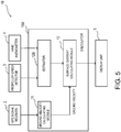
Fig. 5 is a block diagram illustrating a configuration of a surfacecurrent estimating device 1a according to a modification. The surfacecurrent estimating device 1a according to this modification has, different from the surfacecurrent estimating device 1 illustrated inFig. 1 , a configuration in which the couplingcoefficient updating module 14 is omitted. That is, the surfacecurrent estimating device 1a according to this modification does not have a learning function. - The surface
current estimating device 1a according to this modification outputs, as a log velocity, an output value by anestimator 12a of which a coupling coefficient W is determined based on many learning data acquired in advance (data of a ground velocity under a certain condition). Also with such a configuration, similar to the above embodiment, the surface current can easily be calculated. - (2)
Fig. 6 is a block diagram illustrating a configuration of a surfacecurrent estimating device 1b according to a modification. Compared to the surfacecurrent estimating device 1 according to the above embodiment, the surfacecurrent estimating device 1b according to this modification has a significantly different configuration of anestimator 12b. Specifically, theestimator 12b is not configured using a neural network, and has a configuration including amemory 15 and an updatingmodule 16. -
Fig. 7 is a view illustrating in detail theestimator 12b illustrated inFig. 6 . - The
memory 15 stores a matrix table as illustrated inFig. 7 . This table stores ground velocities calculated under respective conditions (corresponding to respective cells of the table). Each condition is defined by a combination of a value of a wind direction and speed (X1, X2, X3, ...) and a value of a rotational speed of a propeller (R1, R2, R3, ...). InFig. 7 , a single value of a ground velocity is indicated with a single circular mark. Specifically, thememory 15 stores, for example, five values of ground velocity calculated when the value of the wind direction and speed is X1 and the value of the rotational speed is R1. - Once the
estimator 12b receives the rotational speed detected by the propeller speed detector 3 (e.g., R2) and the wind direction and speed measured by the vane anemometer 4 (e.g., X3), theestimator 12b calculates an average value of the ground velocities contained in the cell where the rotational speed is R2 and the wind direction and speed is X3 (eleven values in the case ofFig. 7 ). Further, theestimator 12b outputs the average value as an output value. - As described above using
Fig. 4 , by averaging the ground velocities under a certain condition (a condition defined by a combination of a certain rotational speed and a certain wind direction and speed), surface current velocity components contained in the ground velocities cancel out each other, and thus, the average value becomes a value close to a log velocity. Therefore, the log velocity can appropriately be estimated also by theestimator 12b according to this modification. - The updating
module 16 updates the table stored in thememory 15, by using a ground velocity calculated at a timing at which a rotational speed and a wind direction and speed inputted into theestimator 12b are detected. Specifically, the ground velocity calculated at a particular rotational speed (e.g., R3) and a particular wind direction and speed (e.g., X2) is added to a cell defined by R3 and X2. By performing this operation as needed, learning data is accumulated even while traveling, and a log velocity can be estimated more accurately. In other words, theestimator 12b according to this modification also has a learning function. As a result, a surface current velocity can be calculated more accurately. - Note that, by configuring this modification to omit the updating
module 16, a surface current estimating device lc which does not have the learning function (seeFig. 8 ) can be configured. In this case, a plurality of leaning data acquired in advance (each data corresponds to a single circular mark inFig. 7 ) needs to be stored in thememory 15. - (3)
Fig. 9 is a block diagram illustrating a configuration of a surfacecurrent estimating device 1d according to a modification. In this modification, as input values of anestimator 12d, in addition to the rotational speed of the propeller, the true wind speed in the bow direction, and the true wind speed in the starboard direction, a rudder angle, a draft (a distance to a water surface from a bottom of a ship in a state of floating on water), etc. are inputted. Further, theestimator 12d outputs, as an output value, a value corresponding to a condition defined by a combination of respective values of these parameters. Thus, a larger number of parameters can be taken into consideration as parameters which influence a log velocity. Therefore, the log velocity can be obtained more accurately. - Note that, although not illustrated in
Fig. 9 , the parameters which are inputted into theestimator 12d may include information of a wave, a roll angle of the ship, a pitch angle of the ship, an amount of heave of the ship, information of a hydrographic condition, information of a meteorological phenomenon, positional information, etc. Thus, an even more accurate log velocity can be obtained. - (4)
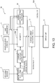
Fig. 10 is a block diagram illustrating a configuration of a surfacecurrent estimating device 1e according to a modification. The surfacecurrent estimating device 1e according to this modification further includes a learningcoefficient setting processor 20. - An
estimator 12e, similar to the case of the above embodiment, is configured using a neural network and such that a coupling coefficient is updated as needed by so-called supervised learning. With the surfacecurrent estimating device 1e, an error between an output value from theestimator 12e and a teaching signal (ground velocity) is calculated. Then, the surfacecurrent estimating device 1e updates the coupling coefficient W while propagating the error as a learning signal, from a unit on an output layer side to a unit on an input layer side. A correction amount of the coupling coefficient is given by the followingEquation 1.
- In
Equation 1, ΔWi,j n,n-1(t) is a correction amount on a weight of coupling between a unit j of an (n-1)th layer and a unit i of an n-th layer, η is a learning coefficient, δi n is a learning signal to be returned back to each unit of the (n-1)th layer from the unit i of the n-th layer, Xj n-1 is an output value of the unit j of the (n-1)th layer, α is a stabilizing coefficient, ΔWi,j n,n-1(t-1) is a previous correction amount. Note that, the (n-1)th layer is one layer on the input side of the n-th layer. -
Fig. 11 is a block diagram illustrating a configuration of the learningcoefficient setting processor 20. The learningcoefficient setting processor 20 sets the learning coefficient inEquation 1 as needed. As illustrated inFig. 11 , the learningcoefficient setting processor 20 has amemory 21, anSOM updating module 22, acounting module 23, a learningcoefficient calculating module 24, and a learningcoefficient setting module 25. -
Fig. 12 is a view schematically illustrating a table stored in thememory 21, and a self-organizing map SOM stored in association with each cell of the table. As illustrated inFig. 12 , thememory 21 stores a table sectioned for every particular propeller rotational speed and every particular wind speed and direction in a grid pattern. Each cell of this table stores a corresponding self-organizing map SOM. Each self-organizing map SOM of this modification is a two-dimensional SOM formed with an nxn number of units. Each unit stores a reference vector of the same dimension as that of an input vector. In an initial state (a state where the learning is not performed), a suitable reference vector is set into the unit. - The
SOM updating module 22 updates the SOM according to the input vector (a vector formed based on a rotational speed of a propeller, a wind direction and speed, a ground velocity, etc. which are inputted at every particular timing). Specifically, theSOM updating module 22 updates as below, the SOM stored in the cell including the inputted rotational speed and the inputted wind direction and speed. - Specifically, by using a unit with a shortest Euclidean distance from the input vector as a winner unit, the
SOM updating module 22 updates a reference vector stored in the winner unit and reference vectors stored in units around the winner unit, based on the followingEquation 2.
- Note that, mi is the reference vector, x(t) is the input vector, and hi is a neighborhood function expressed by c×exp(-dis2/α2). In the neighborhood function, c is a learning rate coefficient, and dis=lx-mcl. Here, mc is a reference vector that minimizes a Euclidean distance from x(t).
- The
SOM updating module 22 updates as needed the self-organizing map SOM by the input vector inputted as needed, by using theEquation 2 described above. - The
counting module 23 counts the number of units having a reference vector of which difference (Euclidean distance) from the input vector becomes a certain threshold or below. - The learning
coefficient calculating module 24 calculates an inverse of the value counted by thecounting module 23, to be the learning coefficient. Specifically, when the count value is high (when the number of similar input data is large), the learning coefficient becomes low, and when the count value is low (when the number of similar input data is small), the learning coefficient becomes high. - The learning
coefficient setting module 25 notifies to theestimator 12e the value calculated by the learningcoefficient calculating module 24, and sets it to be the learning coefficient η inEquation 1. Theestimator 12e updates the coupling coefficient based onEquation 1 by using the learning coefficient η, and then calculates a log velocity vector based on the updated coupling coefficient. - According to this modification, when a large number of similar learning data (input vector) is accumulated, the learning coefficient becomes low. In this case, as apparent from the
Equation 1 described above, the correction amount ΔWi,j n,n-1(t) of the coupling coefficient becomes small. On the other hand, when the similar learning data is not accumulated or only a small number of similar learning data is accumulated, the learning coefficient becomes high. In this case, as apparent fromEquation 1, the correction amount of the coupling coefficient becomes large. Thus, according to this modification, imbalance of the output values from the estimator due to the accumulation of the large number of similar learning data can be reduced. - (5)
Fig. 13 is a block diagram illustrating a configuration of a learningcoefficient setting processor 26 of a surface current estimating device according to a modification. Similar to the case of the learningcoefficient setting processor 20 of the modification described above, the learningcoefficient setting processor 26 according to this modification sets the learning coefficient η ofEquation 1 which is used by an estimator configured using a neural network. However, the learningcoefficient setting processor 26 according to this modification has a different configuration from the learningcoefficient setting processor 20 of the modification described above. As illustrated inFig. 13 , the learningcoefficient setting processor 26 of this modification has amemory 27, a learningcoefficient calculating module 28, and a learningcoefficient setting module 29. -
Fig. 14 is a view illustrating a table stored in thememory 27, and learning data stored in association with each cell (each area) of the table. As illustrated inFig. 14 , similar to the case of the modification described above, thememory 27 stores a table sectioned for every particular propeller rotational speed and every particular wind speed and direction in a grid pattern. In this modification, the learning data stored in each area is mapped corresponding to the ground velocity of each learning data. Specifically, as illustrated inFig. 14 , in a map having a plurality of subareas sectioned for every particular ground velocity in the bow direction and every particular ground velocity in the starboard direction in a grid pattern, each learning data is mapped corresponding to the ground velocity. - The learning
coefficient calculating module 28 sets, as the learning coefficient, a value that is obtained by normalizing an inverse of a value calculated by dividing the number of learning data (four in the case ofFig. 14 ) stored in a subarea which includes learning data inputted at a latest timing, by the number of learning data stored in a subarea with a largest number of learning data (ten in a subarea A in the case ofFig. 14 ) among all the subareas of the area having the subarea which includes the learning data inputted at the latest timing. Further, similar to the learningcoefficient setting module 25 of the above modification, the learningcoefficient setting module 29 notifies to an estimator the learning coefficient set by the learningcoefficient calculating module 28 and sets it to be the learning coefficient η inEquation 1. Also with such a configuration, the learning coefficient can suitably be set. - (6)
Fig. 15 is a block diagram illustrating a configuration of a surfacecurrent estimating device 1f according to a modification. The surfacecurrent estimating device 1f according to this modification is configured to be capable of obtaining, not only a surface current velocity near a first ship, but also a surface current velocity in another marine area. The surfacecurrent estimating device 1f according to this modification includes a secondship information receiver 17. - The second
ship information receiver 17 receives positional information of a second ship traveling on the sea, information of a surface current velocity at a location of the second ship, etc. from the second ship. The secondship information receiver 17 includes an antenna, for example. The secondship information receiver 17 receives, from the second ship as needed, surface current velocity information at each location which the second ship traveling on the sea has passed. -
Fig. 16 is a view illustrating one example of a distribution view of surface current velocities in a wide area, displayed in adisplay unit 5a of this modification. As illustrated inFig. 16 , thedisplay unit 5a of this modification displays surface current velocities calculated at locations which second ships have passed in a particular marine area. In the example illustrated inFig. 16 , the direction of the arrow displayed on the display screen indicates a direction of the surface current, and the size of the arrow indicates a velocity of the surface current. - As above, according to the surface
current estimating device 1f according to this modification, not only the surface current velocity near the first ship position, but also surface current velocities at locations which the first ship has not passed can be obtained. Further, by obtaining the wide area surface current distribution as above, a surface current at a location which is expected that the first ship will pass can be obtained, and the surface current can be utilized as effective information for estimating a time of arrival to a target location and calculating a fuel consumption. - (7)
Fig. 17 is a block diagram illustrating a configuration of a surfacecurrent estimating device 1g according to a modification. Compared to the surfacecurrent estimating device 1f described with reference toFig. 15 , the surfacecurrent estimating device 1g according to this modification is different that it includes a secondship calculating module 18 configured to calculate a surface current velocity of a second ship. - In this modification, a second
ship information receiver 17a acquires a rotational speed of a propeller, wind direction and speed information, positional information, etc. of the second ship as needed. Further, the secondship calculating module 18 calculates a surface current velocity at a location which the second ship has passed, based on these information. The thus calculated surface current velocity vector at the location which the second ship has passed is displayed on thedisplay unit 5a along with a surface current velocity vector at a location which the first ship has passed (seeFig. 16 ). - (8)
Fig. 18 is a block diagram illustrating a configuration of a surfacecurrent estimating device 1h according to a modification. In this modification, aGPS signal receiver 2 etc. which constitute a part of the surfacecurrent estimating device 1h, and acalculator 10h are equipped at separate locations. Specifically, in this modification, theGPS signal receiver 2, apropeller speed detector 3, and avane anemometer 4 are equipped in a first ship, and thecalculator 10h is provided to adata center 30 which is placed on land, for example. Further, the surfacecurrent estimating device 1h according to this modification includes atransmitter 19a and areceiver 19b which are equipped in the first ship. - The
transmitter 19a transmits various data detected by theGPS signal receiver 2, thepropeller speed detector 3, and thevane anemometer 4, to thedata center 30 via antennas. In thecalculator 10h of thedata center 30, based on the various data, a surface current velocity is calculated similarly to the case of the above embodiment. Thecalculator 10h calculates surface current velocities at respective locations which the first ship has passed, and stores them in adatabase unit 31. Thereceiver 19b receives the surface current velocity data stored in thedatabase unit 31. This data is displayed on adisplay unit 5. - In this modification, different from the case of the above embodiment, a calculator with a comparatively high calculation load can be provided at a different location from the first ship. Thus, even without equipping the calculator in the first ship, the surface current velocity at the first ship position can be estimated.
- Note that in this modification, by collecting information of second ships to the
data center 30 and also calculating surface current velocities at positions of the second ships, a wide area surface current distribution can be obtained (seeFig. 19 ). - (9) Moreover, in each of the embodiment and modifications described above, when the accumulation of learning data is not sufficient, the learning data may be complemented.
-
Fig. 20 is a schematic view illustrating complement of the learning data. Since a ship has a substantially laterally symmetrical shape, wind force characteristics (a traveling speed of the ship caused by the wind direction and speed) are estimated to be laterally symmetric. Specifically, for example, between a case where a ship traveling under a certain condition receives a wind from the port quarter at an angle of 45 degrees and a case where the ship receives a wind from the starboard quarter at an angle of 45 degrees (wind speeds are the same), the traveling directions are estimated to be laterally symmetric. Therefore, with reference toFig. 20 , for example, in a case where a propeller rotational speed is a particular speed, a wind direction is on the port quarter at the angle of 45 degrees, and a wind speed is a particular speed, if the ground velocity is VG, the data may be complemented as follows based on the learning data. Specifically, as learning data for when the propeller rotational speed and the wind speed are the same as the learning data of the above case and the wind direction is on the starboard quarter at an angle of 45 degrees, a laterally inverted vector V'G may be complemented. By complementing the learning data as above, for example, even in an initial stage where the accumulation of learning data is not sufficient, an accurate surface current can be estimated. - (10)
Fig. 21 is a block diagram illustrating one example of an oceanmodel estimating apparatus 35. The oceanmodel estimating apparatus 35 is a device including the surface current estimating device described above, and estimates a surface current velocity specific to each location of an ocean, in other words, a location-specific ocean model, according to information of a hydrographic condition and meteorological phenomenon. - As illustrated in
Fig. 21 , the oceanmodel estimating apparatus 35 includes, in addition to the surface current estimating device described above, asecond estimator 36 and a couplingcoefficient updating module 37. - Similar to the case of the
estimator 12 according to the above embodiment, thesecond estimator 36 is configured using a neural network. Further, thesecond estimator 36 is configured to output, as an output value, a surface current velocity according to inputted positional information and the hydrographic condition and meteorological phenomenon information. Note that, examples of the hydrographic condition include a height of tide, atmospheric pressure, and a seawater temperature. - The coupling
coefficient updating module 37 compares the surface current velocity calculated by the surface current calculatingmodule 13 with the output value estimated by thesecond estimator 36, and updates a coupling coefficient of thesecond estimator 36 to reduce an error therebetween. - According to the ocean
model estimating apparatus 35 configured as described above, since the hydrographic condition and meteorological phenomenon information are used as input values, the location-specific surface current velocity according to the hydrographic condition and the meteorological phenomenon can be obtained. Further, by calculating the location-specific surface current velocity at each location on the sea and accumulating them as data, for example, an ocean model for over the world can be structured. - (11)
Fig. 22 is a block diagram illustrating one example of a configuration of adangerousness determining apparatus 40. Thedangerousness determining apparatus 40 is an apparatus including the surface current estimating device described above, and determines a dangerousness of a wave relative to a first ship. - As illustrated in
Fig. 22 , thedangerousness determining apparatus 40 includes, in addition to the surface current estimating device described above, aspectral resolution module 41 and adangerousness determining module 42. Note that, with the surface current estimating device illustrated inFig. 22 , the groundvelocity calculating module 11 calculates a ground velocity in three axial directions (directions in a horizontal plane and a vertical direction), and theestimator 12 calculates a log velocity in the three axial directions. Thus, the surface current calculatingmodule 13 calculates a surface current velocity containing a wave component. - The
spectral resolution module 41 resolves the surface current velocity containing the wave component, which is calculated by the surface current calculatingmodule 13, into a DC component (direct current component) and an AC component (alternate current component). Thespectral resolution module 41 outputs these components to thedangerousness determining module 42. - The
dangerousness determining module 42 determines the respective output values from thespectral resolution module 41 comprehensively to determine the dangerousness of the wave relative to the first ship. Specifically, for example, thedangerousness determining module 42 determines that the dangerousness is low if values of the DC and AC components are comparatively low, and determines that the dangerousness is high if the values of the DC and AC components are comparatively high. The determination result is outputted to adisplay unit 5b. - According to the
dangerousness determining device 40 configured as above, without providing an additional device, such as a transducer, to a bottom of the first ship, a dangerousness of a wave relative to the first ship can be obtained based on a sea surface condition obtained using theGPS signal receiver 2 etc. which are equipped in a general ship. - Note that, with the
dangerousness determining device 40 illustrated inFig. 22 , the dangerousness may be determined by further referring to roll (sway in left-and-right directions with respect to front-and-rear directions of the ship), pitch (sway in the front-and-rear directions with respect to the left-and-right directions of the ship), etc. -
- 1, 1a, 1b, 1c, ..., 1k
- Surface Current Estimating Device
- 11
- Ground Velocity Calculating Module
- 12, 12a, 12b, ..., 12e
- Estimator
- 13
- Surface Current Calculating Module
Claims (14)
- A surface current estimating device (1) that estimates a surface current velocity vector that is a velocity vector of a surface current at a target location where a ship is located on the sea, comprising:a ground velocity calculating module (11) configured to calculate a ground velocity vector of the ship at the target location;an estimator (12) configured to receive an input of one or more values of at least one parameter at the target location, and estimate and output, as a log velocity vector of the ship, a value corresponding to one of conditions, the at least one parameter causing an influence on the log velocity vector of the ship, each of the conditions defined by a combination of the received values; anda surface current calculating module (13) configured to calculate the surface current velocity vector of the target location, based on the output value as the log velocity vector estimated by the estimator (12) and the ground velocity vector calculated by the ground velocity calculating module (11).
- The surface current estimating device (1) of claim 1, wherein the estimator (12) is configured either using a neural network or to output, as the output value, an average value of ground velocity vectors calculated by the ground velocity calculating module (11) to correspond to the one of the conditions.
- The surface current estimating device (1) of claim 1 or 2, further comprising an updating module (14) configured to compare the output value from the estimator (12) with the ground velocity vector calculated by the ground velocity calculating module (11), and update the estimator (12) to reduce an error between the output value and the ground velocity vector.
- The surface current estimating device (1) of claim 3, wherein the estimator (12) is configured using a neural network,
wherein the estimator (12) has at least one input unit configured to receive a value corresponding to one of the at least one parameter and an output unit configured to output the output value that is the log velocity vector,
wherein a value to be outputted from the input unit of the neural network is multiplied by a coupling coefficient and then transmitted to the output unit, and
wherein the updating module (14) compares the output value with the ground velocity vector that is a teaching signal, and updates the coupling coefficient to reduce an error between the output value and the teaching signal. - The surface current estimating device (1) of any one of claims 1 to 4, wherein the surface current calculating module (13) calculates the surface current velocity vector by subtracting the log velocity vector estimated by the estimator (12) from the ground velocity vector calculated by the ground velocity calculating module (11).
- The surface current estimating device (1) of any one of claims 1 to 5, further comprising a GNSS signal receiver (2) equipped in the ship and configured to receive GNSS signals,
wherein the ground velocity calculating module (11) calculates the ground velocity vector based on the GNSS signals received by the GNSS signal receiver (2) and time points at which the GNSS signals are received. - The surface current estimating device (1) of any one of claims 1 to 6, wherein the at least one parameter includes one of a rotational speed of a propeller of the ship, information of a wind direction and a wind speed, a rudder angle of the ship, a draft of the ship, information of a wave, a roll angle of the ship, a pitch angle of the ship, an amount of heave of the ship, information of a hydrographic condition, information of a meteorological phenomenon, and positional information.
- The surface current estimating device (1) of claim 7, further comprising:a propeller speed detector (3) configured to detect the rotational speed of the propeller; anda vane anemometer (4) equipped in the ship,wherein the estimator (12) receives at least the rotational speed of the propeller detected by the propeller speed detector (3), and the information of the wind direction and the wind speed measured by the vane anemometer (4).
- The surface current estimating device (1) of any one of claims 1 to 8, wherein the surface current estimating device (1) is equipped in a first ship that is the ship.
- A surface current estimating system, comprising:a calculator (10) including the ground velocity calculating module (11), the estimator (12), and the surface current calculating module (13) of the surface current estimating device (1) of any one of claims 1 to 8, the calculator (10) equipped at a location different from that of a first ship that is the ship;a transmitter (19a) equipped in the first ship and configured to transmit to the calculator (10) the one or more values of the at least one parameter that causes the influence on the log velocity vector of the first ship; anda receiver (19b) equipped in the first ship and configured to receive the surface current velocity vector of the target location, the surface current velocity vector calculated by the calculator.
- The surface current estimating system of claim 10, wherein the calculator (10) also calculates a surface current velocity vector of a location where a second ship is located, based on one or more values of the at least one parameter regarding the second ship, and
wherein the receiver (19b) also receives the surface current velocity vector of the location where the second ship is located, the surface current velocity vector calculated by the calculator (10). - The surface current estimating system of claim 11, further comprising a display unit (5) configured to display a desired area on the sea and capable of displaying the surface current velocity vector of the target location of the first ship within the desired area, and the surface current velocity vector of the location where the second ship is located within the desired area.
- An ocean model estimating apparatus (35), comprising one of the surface current estimating device (1) of any one of claims 1 to 9 and the surface current estimating system of claim 10 or 11,
wherein the estimator (12) of the one of the surface current estimating device (1) and the surface current estimating system is provided as a first estimator (12), and
further comprising a second estimator (36) configured using a neural network and configured to receive positional information of a first ship, information of a current hydrographic condition, and information of a meteorological phenomenon, output, as an output value, a value corresponding to one of conditions, and be updated to reduce an error between a surface current velocity vector and the output value, each of the conditions defined by a combination of the received information, the surface current velocity vector calculated as a teaching signal by the one of the surface current estimating device (1) and the surface current estimating system. - A dangerousness determining apparatus (40), comprising:one of the surface current estimating device (1) of any one of claims 1 to 9 and the surface current estimating system of claim 10 or 11; anda determining module (42) configured to determine a dangerousness of a wave relative to a first ship based on at least the surface current velocity vector estimated by the one of the surface current estimating device (1) and the surface current estimating system.
Applications Claiming Priority (2)
| Application Number | Priority Date | Filing Date | Title |
|---|---|---|---|
| JP2014034478 | 2014-02-25 | ||
| PCT/JP2015/051301 WO2015129337A1 (en) | 2014-02-25 | 2015-01-20 | Surface current estimation device, surface current estimation system, ocean model estimation device, and risk determination device |
Publications (3)
| Publication Number | Publication Date |
|---|---|
| EP3112877A1 true EP3112877A1 (en) | 2017-01-04 |
| EP3112877A4 EP3112877A4 (en) | 2017-08-02 |
| EP3112877B1 EP3112877B1 (en) | 2018-07-18 |
Family
ID=54008666
Family Applications (1)
| Application Number | Title | Priority Date | Filing Date |
|---|---|---|---|
| EP15754998.1A Active EP3112877B1 (en) | 2014-02-25 | 2015-01-20 | Surface current estimation device, surface current estimation system, ocean model estimation device, and risk determination device |
Country Status (3)
| Country | Link |
|---|---|
| EP (1) | EP3112877B1 (en) |
| JP (1) | JP6340067B2 (en) |
| WO (1) | WO2015129337A1 (en) |
Families Citing this family (6)
| Publication number | Priority date | Publication date | Assignee | Title |
|---|---|---|---|---|
| CN109562819B (en) | 2016-08-09 | 2021-07-06 | 艾妮拉姆公司 | Method and sensor system for determining the speed of a seagoing vessel over water |
| CN111220813B (en) * | 2020-01-13 | 2022-01-11 | 广州船舶及海洋工程设计研究院(中国船舶工业集团公司第六0五研究院) | Ship speed determination method, endurance mileage determination method, device and system |
| US12461495B2 (en) | 2022-05-17 | 2025-11-04 | Furuno Electric Co., Ltd. | Disturbance estimating apparatus, method, and computer program |
| US12208869B2 (en) | 2022-06-15 | 2025-01-28 | Furuno Electric Co., Ltd. | Disturbance estimating apparatus, method, and computer program |
| KR102631383B1 (en) * | 2023-04-21 | 2024-01-31 | 주식회사 테렌즈 | Predicting method for operating variable of ship based on artificial intelligence and computer readable recording medium for the same |
| JP7489150B1 (en) | 2023-11-30 | 2024-05-23 | 陽一 金子 | Anemometer, wind speed calculation method, and program |
Family Cites Families (13)
| Publication number | Priority date | Publication date | Assignee | Title |
|---|---|---|---|---|
| JPS61159107A (en) * | 1984-12-29 | 1986-07-18 | Japan Radio Co Ltd | Receiving device for ship |
| JPH11237477A (en) * | 1998-02-20 | 1999-08-31 | Nagano Japan Radio Co | Marine radar using shortwave or ultrashortwave and marine radar system using shortwave or ultrashortwave |
| JP2001264437A (en) * | 2000-03-22 | 2001-09-26 | Furuno Electric Co Ltd | System device, and method for measuring distribution of tidal current, and underwater detection system |
| JP3949932B2 (en) * | 2001-10-30 | 2007-07-25 | 三井造船株式会社 | Autonomous underwater vehicle navigation control system |
| JP2003344437A (en) * | 2002-05-27 | 2003-12-03 | Yamaha Motor Co Ltd | Ground speed calculation method and ground speed calculation device |
| JP2004226374A (en) * | 2003-01-27 | 2004-08-12 | Tech Res & Dev Inst Of Japan Def Agency | Position measurement system, position measurement method, program, and vehicle operating system |
| JP2004233185A (en) * | 2003-01-30 | 2004-08-19 | Yokogawa Electric Corp | High-performance GPS and navigation system using it |
| KR100868849B1 (en) * | 2007-01-30 | 2008-11-14 | 현대중공업 주식회사 | How to Select the Optimal Course for Ship Speed Test |
| JP5191263B2 (en) * | 2008-04-07 | 2013-05-08 | 日本郵船株式会社 | Ship navigational state analyzer |
| IL192518A (en) * | 2008-06-30 | 2013-02-28 | Michael Naumov | Method and device for the autonomous determination of wind speed vector |
| JP2011210551A (en) * | 2010-03-30 | 2011-10-20 | Nec Lighting Ltd | Globe of lighting apparatus, filter for lighting apparatus, and lighting apparatus |
| JP5033210B2 (en) * | 2010-03-31 | 2012-09-26 | 三井造船株式会社 | Ship main engine control system and method |
| JP6036515B2 (en) * | 2013-04-22 | 2016-11-30 | 株式会社Ihi | Underwater vehicle |
-
2015
- 2015-01-20 WO PCT/JP2015/051301 patent/WO2015129337A1/en not_active Ceased
- 2015-01-20 JP JP2016505097A patent/JP6340067B2/en not_active Expired - Fee Related
- 2015-01-20 EP EP15754998.1A patent/EP3112877B1/en active Active
Also Published As
| Publication number | Publication date |
|---|---|
| JP6340067B2 (en) | 2018-06-06 |
| EP3112877A4 (en) | 2017-08-02 |
| JPWO2015129337A1 (en) | 2017-03-30 |
| WO2015129337A1 (en) | 2015-09-03 |
| EP3112877B1 (en) | 2018-07-18 |
Similar Documents
| Publication | Publication Date | Title |
|---|---|---|
| EP3176068B1 (en) | Vessel characteristic estimation device and automatic steering device | |
| EP3112877B1 (en) | Surface current estimation device, surface current estimation system, ocean model estimation device, and risk determination device | |
| US12061083B2 (en) | System and method for wave prediction | |
| McMillan et al. | Rates of dissipation of turbulent kinetic energy in a high Reynolds number tidal channel | |
| Thomson et al. | A new version of the SWIFT platform for waves, currents, and turbulence in the ocean surface layer | |
| RU2483280C1 (en) | Navigation system | |
| RU2536768C1 (en) | Method of inertial-satellite navigation of aircrafts | |
| CN107430004A (en) | Method for the method for the water surface speed of at least one ship of calculating and for deriving the shift vectors on the path of the ship at each point | |
| KR101790481B1 (en) | Sea surface wind measurement system and method using marine rader | |
| US20160195626A1 (en) | Method and System for Determining the Position of Control Devices on a Seismic Instrumented Towed Cable | |
| EP3006322B1 (en) | Navigation assistance device, navigation assistance method, and program | |
| Løken et al. | Wave measurements from ship mounted sensors in the Arctic marginal ice zone | |
| RU2490679C1 (en) | Buoy for determining characteristics of sea waves | |
| EP3006321A1 (en) | Environment information detection device for ships, route setting device, environment information detection method for ships, and program | |
| JP6154540B2 (en) | Ship characteristic estimation device | |
| Tippenhauer et al. | Turbulence and finestructure in a deep ocean channel with sill overflow on the mid-Atlantic ridge | |
| WO2016098491A1 (en) | Optimum rotation speed estimation device, optimum rotation speed estimation system, and rotation speed control device | |
| Schmaljohann et al. | Motion estimation for synthetic aperture sonars | |
| Henley et al. | Performance of 3D forward looking sonar for bathymetric survey | |
| Zhang et al. | Acoustic Doppler velocimeter flow measurement from an autonomous underwater vehicle with applications to deep ocean convection | |
| Hagen et al. | Low altitude AUV terrain navigation using an interferometric sidescan sonar | |
| Shi et al. | Experimental setup and investigation of deep-sea navigation and positioning network | |
| KR101554615B1 (en) | Apparatus and method for estimating size of external force applied to ships and apparatus for generating ships route information | |
| RU2712799C1 (en) | Hydroacoustic navigation device with four-element short-base receiving antenna | |
| De Girolamo et al. | Wave characteristics estimation by GPS receivers installed on a sailboat travelling off-shore |
Legal Events
| Date | Code | Title | Description |
|---|---|---|---|
| PUAI | Public reference made under article 153(3) epc to a published international application that has entered the european phase |
Free format text: ORIGINAL CODE: 0009012 |
|
| STAA | Information on the status of an ep patent application or granted ep patent |
Free format text: STATUS: REQUEST FOR EXAMINATION WAS MADE |
|
| 17P | Request for examination filed |
Effective date: 20160816 |
|
| AK | Designated contracting states |
Kind code of ref document: A1 Designated state(s): AL AT BE BG CH CY CZ DE DK EE ES FI FR GB GR HR HU IE IS IT LI LT LU LV MC MK MT NL NO PL PT RO RS SE SI SK SM TR |
|
| AX | Request for extension of the european patent |
Extension state: BA ME |
|
| DAX | Request for extension of the european patent (deleted) | ||
| A4 | Supplementary search report drawn up and despatched |
Effective date: 20170705 |
|
| RIC1 | Information provided on ipc code assigned before grant |
Ipc: G01P 13/00 20060101ALI20170629BHEP Ipc: B63B 39/14 20060101ALI20170629BHEP Ipc: B63B 49/00 20060101ALI20170629BHEP Ipc: G01P 5/00 20060101AFI20170629BHEP |
|
| GRAP | Despatch of communication of intention to grant a patent |
Free format text: ORIGINAL CODE: EPIDOSNIGR1 |
|
| STAA | Information on the status of an ep patent application or granted ep patent |
Free format text: STATUS: GRANT OF PATENT IS INTENDED |
|
| RIN1 | Information on inventor provided before grant (corrected) |
Inventor name: KAWASAKI, CHIZU Inventor name: MAENO, HITOSHI Inventor name: IMASAKA, MASASHI |
|
| INTG | Intention to grant announced |
Effective date: 20180327 |
|
| GRAS | Grant fee paid |
Free format text: ORIGINAL CODE: EPIDOSNIGR3 |
|
| GRAA | (expected) grant |
Free format text: ORIGINAL CODE: 0009210 |
|
| STAA | Information on the status of an ep patent application or granted ep patent |
Free format text: STATUS: THE PATENT HAS BEEN GRANTED |
|
| AK | Designated contracting states |
Kind code of ref document: B1 Designated state(s): AL AT BE BG CH CY CZ DE DK EE ES FI FR GB GR HR HU IE IS IT LI LT LU LV MC MK MT NL NO PL PT RO RS SE SI SK SM TR |
|
| REG | Reference to a national code |
Ref country code: GB Ref legal event code: FG4D |
|
| REG | Reference to a national code |
Ref country code: CH Ref legal event code: EP |
|
| REG | Reference to a national code |
Ref country code: IE Ref legal event code: FG4D |
|
| REG | Reference to a national code |
Ref country code: AT Ref legal event code: REF Ref document number: 1019935 Country of ref document: AT Kind code of ref document: T Effective date: 20180815 |
|
| REG | Reference to a national code |
Ref country code: DE Ref legal event code: R096 Ref document number: 602015013786 Country of ref document: DE |
|
| REG | Reference to a national code |
Ref country code: NL Ref legal event code: MP Effective date: 20180718 |
|
| REG | Reference to a national code |
Ref country code: LT Ref legal event code: MG4D |
|
| REG | Reference to a national code |
Ref country code: AT Ref legal event code: MK05 Ref document number: 1019935 Country of ref document: AT Kind code of ref document: T Effective date: 20180718 |
|
| PG25 | Lapsed in a contracting state [announced via postgrant information from national office to epo] |
Ref country code: NL Free format text: LAPSE BECAUSE OF FAILURE TO SUBMIT A TRANSLATION OF THE DESCRIPTION OR TO PAY THE FEE WITHIN THE PRESCRIBED TIME-LIMIT Effective date: 20180718 |
|
| PG25 | Lapsed in a contracting state [announced via postgrant information from national office to epo] |
Ref country code: AT Free format text: LAPSE BECAUSE OF FAILURE TO SUBMIT A TRANSLATION OF THE DESCRIPTION OR TO PAY THE FEE WITHIN THE PRESCRIBED TIME-LIMIT Effective date: 20180718 Ref country code: BG Free format text: LAPSE BECAUSE OF FAILURE TO SUBMIT A TRANSLATION OF THE DESCRIPTION OR TO PAY THE FEE WITHIN THE PRESCRIBED TIME-LIMIT Effective date: 20181018 Ref country code: SE Free format text: LAPSE BECAUSE OF FAILURE TO SUBMIT A TRANSLATION OF THE DESCRIPTION OR TO PAY THE FEE WITHIN THE PRESCRIBED TIME-LIMIT Effective date: 20180718 Ref country code: LT Free format text: LAPSE BECAUSE OF FAILURE TO SUBMIT A TRANSLATION OF THE DESCRIPTION OR TO PAY THE FEE WITHIN THE PRESCRIBED TIME-LIMIT Effective date: 20180718 Ref country code: PL Free format text: LAPSE BECAUSE OF FAILURE TO SUBMIT A TRANSLATION OF THE DESCRIPTION OR TO PAY THE FEE WITHIN THE PRESCRIBED TIME-LIMIT Effective date: 20180718 Ref country code: FI Free format text: LAPSE BECAUSE OF FAILURE TO SUBMIT A TRANSLATION OF THE DESCRIPTION OR TO PAY THE FEE WITHIN THE PRESCRIBED TIME-LIMIT Effective date: 20180718 Ref country code: IS Free format text: LAPSE BECAUSE OF FAILURE TO SUBMIT A TRANSLATION OF THE DESCRIPTION OR TO PAY THE FEE WITHIN THE PRESCRIBED TIME-LIMIT Effective date: 20181118 Ref country code: RS Free format text: LAPSE BECAUSE OF FAILURE TO SUBMIT A TRANSLATION OF THE DESCRIPTION OR TO PAY THE FEE WITHIN THE PRESCRIBED TIME-LIMIT Effective date: 20180718 Ref country code: GR Free format text: LAPSE BECAUSE OF FAILURE TO SUBMIT A TRANSLATION OF THE DESCRIPTION OR TO PAY THE FEE WITHIN THE PRESCRIBED TIME-LIMIT Effective date: 20181019 Ref country code: NO Free format text: LAPSE BECAUSE OF FAILURE TO SUBMIT A TRANSLATION OF THE DESCRIPTION OR TO PAY THE FEE WITHIN THE PRESCRIBED TIME-LIMIT Effective date: 20181018 |
|
| PG25 | Lapsed in a contracting state [announced via postgrant information from national office to epo] |
Ref country code: LV Free format text: LAPSE BECAUSE OF FAILURE TO SUBMIT A TRANSLATION OF THE DESCRIPTION OR TO PAY THE FEE WITHIN THE PRESCRIBED TIME-LIMIT Effective date: 20180718 Ref country code: HR Free format text: LAPSE BECAUSE OF FAILURE TO SUBMIT A TRANSLATION OF THE DESCRIPTION OR TO PAY THE FEE WITHIN THE PRESCRIBED TIME-LIMIT Effective date: 20180718 Ref country code: AL Free format text: LAPSE BECAUSE OF FAILURE TO SUBMIT A TRANSLATION OF THE DESCRIPTION OR TO PAY THE FEE WITHIN THE PRESCRIBED TIME-LIMIT Effective date: 20180718 |
|
| REG | Reference to a national code |
Ref country code: DE Ref legal event code: R097 Ref document number: 602015013786 Country of ref document: DE |
|
| PG25 | Lapsed in a contracting state [announced via postgrant information from national office to epo] |
Ref country code: RO Free format text: LAPSE BECAUSE OF FAILURE TO SUBMIT A TRANSLATION OF THE DESCRIPTION OR TO PAY THE FEE WITHIN THE PRESCRIBED TIME-LIMIT Effective date: 20180718 Ref country code: CZ Free format text: LAPSE BECAUSE OF FAILURE TO SUBMIT A TRANSLATION OF THE DESCRIPTION OR TO PAY THE FEE WITHIN THE PRESCRIBED TIME-LIMIT Effective date: 20180718 Ref country code: IT Free format text: LAPSE BECAUSE OF FAILURE TO SUBMIT A TRANSLATION OF THE DESCRIPTION OR TO PAY THE FEE WITHIN THE PRESCRIBED TIME-LIMIT Effective date: 20180718 Ref country code: EE Free format text: LAPSE BECAUSE OF FAILURE TO SUBMIT A TRANSLATION OF THE DESCRIPTION OR TO PAY THE FEE WITHIN THE PRESCRIBED TIME-LIMIT Effective date: 20180718 Ref country code: ES Free format text: LAPSE BECAUSE OF FAILURE TO SUBMIT A TRANSLATION OF THE DESCRIPTION OR TO PAY THE FEE WITHIN THE PRESCRIBED TIME-LIMIT Effective date: 20180718 |
|
| PLBE | No opposition filed within time limit |
Free format text: ORIGINAL CODE: 0009261 |
|
| STAA | Information on the status of an ep patent application or granted ep patent |
Free format text: STATUS: NO OPPOSITION FILED WITHIN TIME LIMIT |
|
| PG25 | Lapsed in a contracting state [announced via postgrant information from national office to epo] |
Ref country code: SK Free format text: LAPSE BECAUSE OF FAILURE TO SUBMIT A TRANSLATION OF THE DESCRIPTION OR TO PAY THE FEE WITHIN THE PRESCRIBED TIME-LIMIT Effective date: 20180718 Ref country code: DK Free format text: LAPSE BECAUSE OF FAILURE TO SUBMIT A TRANSLATION OF THE DESCRIPTION OR TO PAY THE FEE WITHIN THE PRESCRIBED TIME-LIMIT Effective date: 20180718 Ref country code: SM Free format text: LAPSE BECAUSE OF FAILURE TO SUBMIT A TRANSLATION OF THE DESCRIPTION OR TO PAY THE FEE WITHIN THE PRESCRIBED TIME-LIMIT Effective date: 20180718 |
|
| 26N | No opposition filed |
Effective date: 20190423 |
|
| PG25 | Lapsed in a contracting state [announced via postgrant information from national office to epo] |
Ref country code: SI Free format text: LAPSE BECAUSE OF FAILURE TO SUBMIT A TRANSLATION OF THE DESCRIPTION OR TO PAY THE FEE WITHIN THE PRESCRIBED TIME-LIMIT Effective date: 20180718 Ref country code: MC Free format text: LAPSE BECAUSE OF FAILURE TO SUBMIT A TRANSLATION OF THE DESCRIPTION OR TO PAY THE FEE WITHIN THE PRESCRIBED TIME-LIMIT Effective date: 20180718 |
|
| REG | Reference to a national code |
Ref country code: CH Ref legal event code: PL |
|
| PG25 | Lapsed in a contracting state [announced via postgrant information from national office to epo] |
Ref country code: LU Free format text: LAPSE BECAUSE OF NON-PAYMENT OF DUE FEES Effective date: 20190120 |
|
| REG | Reference to a national code |
Ref country code: BE Ref legal event code: MM Effective date: 20190131 |
|
| REG | Reference to a national code |
Ref country code: IE Ref legal event code: MM4A |
|
| PG25 | Lapsed in a contracting state [announced via postgrant information from national office to epo] |
Ref country code: BE Free format text: LAPSE BECAUSE OF NON-PAYMENT OF DUE FEES Effective date: 20190131 |
|
| PG25 | Lapsed in a contracting state [announced via postgrant information from national office to epo] |
Ref country code: LI Free format text: LAPSE BECAUSE OF NON-PAYMENT OF DUE FEES Effective date: 20190131 Ref country code: CH Free format text: LAPSE BECAUSE OF NON-PAYMENT OF DUE FEES Effective date: 20190131 |
|
| PG25 | Lapsed in a contracting state [announced via postgrant information from national office to epo] |
Ref country code: IE Free format text: LAPSE BECAUSE OF NON-PAYMENT OF DUE FEES Effective date: 20190120 |
|
| PG25 | Lapsed in a contracting state [announced via postgrant information from national office to epo] |
Ref country code: TR Free format text: LAPSE BECAUSE OF FAILURE TO SUBMIT A TRANSLATION OF THE DESCRIPTION OR TO PAY THE FEE WITHIN THE PRESCRIBED TIME-LIMIT Effective date: 20180718 |
|
| PG25 | Lapsed in a contracting state [announced via postgrant information from national office to epo] |
Ref country code: PT Free format text: LAPSE BECAUSE OF FAILURE TO SUBMIT A TRANSLATION OF THE DESCRIPTION OR TO PAY THE FEE WITHIN THE PRESCRIBED TIME-LIMIT Effective date: 20181118 Ref country code: MT Free format text: LAPSE BECAUSE OF NON-PAYMENT OF DUE FEES Effective date: 20190120 |
|
| PG25 | Lapsed in a contracting state [announced via postgrant information from national office to epo] |
Ref country code: CY Free format text: LAPSE BECAUSE OF FAILURE TO SUBMIT A TRANSLATION OF THE DESCRIPTION OR TO PAY THE FEE WITHIN THE PRESCRIBED TIME-LIMIT Effective date: 20180718 |
|
| PG25 | Lapsed in a contracting state [announced via postgrant information from national office to epo] |
Ref country code: HU Free format text: LAPSE BECAUSE OF FAILURE TO SUBMIT A TRANSLATION OF THE DESCRIPTION OR TO PAY THE FEE WITHIN THE PRESCRIBED TIME-LIMIT; INVALID AB INITIO Effective date: 20150120 |
|
| PG25 | Lapsed in a contracting state [announced via postgrant information from national office to epo] |
Ref country code: MK Free format text: LAPSE BECAUSE OF FAILURE TO SUBMIT A TRANSLATION OF THE DESCRIPTION OR TO PAY THE FEE WITHIN THE PRESCRIBED TIME-LIMIT Effective date: 20180718 |
|
| P01 | Opt-out of the competence of the unified patent court (upc) registered |
Effective date: 20230523 |
|
| PGFP | Annual fee paid to national office [announced via postgrant information from national office to epo] |
Ref country code: GB Payment date: 20231130 Year of fee payment: 10 |
|
| PGFP | Annual fee paid to national office [announced via postgrant information from national office to epo] |
Ref country code: DE Payment date: 20231128 Year of fee payment: 10 |
|
| PGFP | Annual fee paid to national office [announced via postgrant information from national office to epo] |
Ref country code: FR Payment date: 20250327 Year of fee payment: 11 |
|
| REG | Reference to a national code |
Ref country code: DE Ref legal event code: R119 Ref document number: 602015013786 Country of ref document: DE |
|
| GBPC | Gb: european patent ceased through non-payment of renewal fee |
Effective date: 20250120 |
|
| PG25 | Lapsed in a contracting state [announced via postgrant information from national office to epo] |
Ref country code: DE Free format text: LAPSE BECAUSE OF NON-PAYMENT OF DUE FEES Effective date: 20250801 |
|
| PG25 | Lapsed in a contracting state [announced via postgrant information from national office to epo] |
Ref country code: GB Free format text: LAPSE BECAUSE OF NON-PAYMENT OF DUE FEES Effective date: 20250120 |