EP3112822A1 - Aircraft fuel measurement - Google Patents
Aircraft fuel measurement Download PDFInfo
- Publication number
- EP3112822A1 EP3112822A1 EP16173251.6A EP16173251A EP3112822A1 EP 3112822 A1 EP3112822 A1 EP 3112822A1 EP 16173251 A EP16173251 A EP 16173251A EP 3112822 A1 EP3112822 A1 EP 3112822A1
- Authority
- EP
- European Patent Office
- Prior art keywords
- fuel
- light
- flight
- sensor
- path
- Prior art date
- Legal status (The legal status is an assumption and is not a legal conclusion. Google has not performed a legal analysis and makes no representation as to the accuracy of the status listed.)
- Granted
Links
Images




Classifications
-
- G—PHYSICS
- G01—MEASURING; TESTING
- G01F—MEASURING VOLUME, VOLUME FLOW, MASS FLOW OR LIQUID LEVEL; METERING BY VOLUME
- G01F23/00—Indicating or measuring liquid level or level of fluent solid material, e.g. indicating in terms of volume or indicating by means of an alarm
- G01F23/22—Indicating or measuring liquid level or level of fluent solid material, e.g. indicating in terms of volume or indicating by means of an alarm by measuring physical variables, other than linear dimensions, pressure or weight, dependent on the level to be measured, e.g. by difference of heat transfer of steam or water
- G01F23/28—Indicating or measuring liquid level or level of fluent solid material, e.g. indicating in terms of volume or indicating by means of an alarm by measuring physical variables, other than linear dimensions, pressure or weight, dependent on the level to be measured, e.g. by difference of heat transfer of steam or water by measuring the variations of parameters of electromagnetic or acoustic waves applied directly to the liquid or fluent solid material
- G01F23/284—Electromagnetic waves
- G01F23/292—Light, e.g. infrared or ultraviolet
-
- B—PERFORMING OPERATIONS; TRANSPORTING
- B64—AIRCRAFT; AVIATION; COSMONAUTICS
- B64D—EQUIPMENT FOR FITTING IN OR TO AIRCRAFT; FLIGHT SUITS; PARACHUTES; ARRANGEMENT OR MOUNTING OF POWER PLANTS OR PROPULSION TRANSMISSIONS IN AIRCRAFT
- B64D37/00—Arrangements in connection with fuel supply for power plant
- B64D37/005—Accessories not provided for in the groups B64D37/02 - B64D37/28
-
- G—PHYSICS
- G01—MEASURING; TESTING
- G01F—MEASURING VOLUME, VOLUME FLOW, MASS FLOW OR LIQUID LEVEL; METERING BY VOLUME
- G01F23/00—Indicating or measuring liquid level or level of fluent solid material, e.g. indicating in terms of volume or indicating by means of an alarm
- G01F23/22—Indicating or measuring liquid level or level of fluent solid material, e.g. indicating in terms of volume or indicating by means of an alarm by measuring physical variables, other than linear dimensions, pressure or weight, dependent on the level to be measured, e.g. by difference of heat transfer of steam or water
- G01F23/28—Indicating or measuring liquid level or level of fluent solid material, e.g. indicating in terms of volume or indicating by means of an alarm by measuring physical variables, other than linear dimensions, pressure or weight, dependent on the level to be measured, e.g. by difference of heat transfer of steam or water by measuring the variations of parameters of electromagnetic or acoustic waves applied directly to the liquid or fluent solid material
- G01F23/284—Electromagnetic waves
- G01F23/292—Light, e.g. infrared or ultraviolet
- G01F23/2921—Light, e.g. infrared or ultraviolet for discrete levels
- G01F23/2928—Light, e.g. infrared or ultraviolet for discrete levels using light reflected on the material surface
-
- G—PHYSICS
- G01—MEASURING; TESTING
- G01F—MEASURING VOLUME, VOLUME FLOW, MASS FLOW OR LIQUID LEVEL; METERING BY VOLUME
- G01F23/00—Indicating or measuring liquid level or level of fluent solid material, e.g. indicating in terms of volume or indicating by means of an alarm
- G01F23/80—Arrangements for signal processing
-
- G—PHYSICS
- G01—MEASURING; TESTING
- G01S—RADIO DIRECTION-FINDING; RADIO NAVIGATION; DETERMINING DISTANCE OR VELOCITY BY USE OF RADIO WAVES; LOCATING OR PRESENCE-DETECTING BY USE OF THE REFLECTION OR RERADIATION OF RADIO WAVES; ANALOGOUS ARRANGEMENTS USING OTHER WAVES
- G01S17/00—Systems using the reflection or reradiation of electromagnetic waves other than radio waves, e.g. lidar systems
- G01S17/02—Systems using the reflection of electromagnetic waves other than radio waves
- G01S17/06—Systems determining position data of a target
- G01S17/08—Systems determining position data of a target for measuring distance only
- G01S17/10—Systems determining position data of a target for measuring distance only using transmission of interrupted, pulse-modulated waves
-
- G—PHYSICS
- G01—MEASURING; TESTING
- G01S—RADIO DIRECTION-FINDING; RADIO NAVIGATION; DETERMINING DISTANCE OR VELOCITY BY USE OF RADIO WAVES; LOCATING OR PRESENCE-DETECTING BY USE OF THE REFLECTION OR RERADIATION OF RADIO WAVES; ANALOGOUS ARRANGEMENTS USING OTHER WAVES
- G01S17/00—Systems using the reflection or reradiation of electromagnetic waves other than radio waves, e.g. lidar systems
- G01S17/88—Lidar systems specially adapted for specific applications
-
- G—PHYSICS
- G01—MEASURING; TESTING
- G01S—RADIO DIRECTION-FINDING; RADIO NAVIGATION; DETERMINING DISTANCE OR VELOCITY BY USE OF RADIO WAVES; LOCATING OR PRESENCE-DETECTING BY USE OF THE REFLECTION OR RERADIATION OF RADIO WAVES; ANALOGOUS ARRANGEMENTS USING OTHER WAVES
- G01S7/00—Details of systems according to groups G01S13/00, G01S15/00, G01S17/00
- G01S7/48—Details of systems according to groups G01S13/00, G01S15/00, G01S17/00 of systems according to group G01S17/00
- G01S7/497—Means for monitoring or calibrating
Definitions
- the present invention relates to a method of estimating a quantity of a liquid fuel in a fuel tank of an aircraft, and related apparatus.
- US2015/0153212 discloses a method of measuring a height of a fuel surface of fuel in an aircraft fuel tank.
- One or more images of the fuel surface are captured, each image including a fuel surface line where the fuel surface meets a structure.
- Each image is analysed in order to determine a height of the fuel surface line at three or more points in the image. If the fuel surface line is not a straight line, then an average angle of the fuel surface line can be determined from the points in the image by spatial averaging.
- Preferably a series of images of the fuel surface are captured over a time period, and an average height of the fuel surface is determined from the series of images by time averaging.
- the height of the fuel surface line(s) at three or more points is used to determine a volume of the fuel, a mass of the fuel, and/or an attitude of the fuel surface.
- a Time-of-Flight Camera is a range imaging camera system that resolves distance based on the known speed of light.
- a ToF Camera is based on the laser rangefinder principle: a very short laser pulse is sent against a target and the time-of-flight (i.e. the time the laser pulse takes to be reflected and to come back to the receiver) is measured. Knowing the speed of propagation of the light the distance can be resolved.
- a ToF Camera is a 3D version of a laser rangefinder, where the receiver is a matrix of pixels, and each pixel is able to measure the time-of-flight for the emitted light/laser pulse reflected by a specific region of a 3D object.
- the final result is a 3D map (or distance map) of the real 3D object.
- a 3-D imaging system is described in WO2006/097406 .
- a photodiode or sensor cell are placed in an illumination unit.
- the sensor cell provides a phase reference essentially corresponding to a zero distance measurement.
- a first aspect of the invention provides an aircraft fuel tank system comprising: a fuel tank; an array of sensors; a light source arranged to illuminate a surface of a liquid fuel in the fuel tank with light so that the light is reflected or scattered by the surface of the fuel onto an array of sensors, the light travelling to and from the surface of the fuel via a measurement path containing a transmission medium, wherein the light source is also arranged to illuminate at least one sensor of the array of sensors with light via a reference path containing a transmission medium with substantially the same refractive index as the transmission medium in the measurement path, the reference path having a known reference distance which does not vary in accordance with the quantity of the fuel; and a processing system arranged to determine a measured time of flight of the light which travels via the measurement path to each sensor of the array of sensors, measure a reference time of flight of the light which travels via the reference path to said at least one sensor, and estimate the quantity of the fuel in the fuel tank in accordance with the measured times of flight, the reference time of flight and the known reference distance.
- the light may be reflected or scattered by the surface of the fuel onto the array of sensors such that each sensor of the array of sensors receives reflected light from a respective location of a plurality of locations on the surface of the fuel, and the processing system may be arranged to determine a measured time of flight of the light which travels via the measurement path to each sensor of the array of sensors to thereby determine a measured time of flight for each respective location of the plurality of locations on the surface of the fuel.
- a further aspect of the invention provides a method of estimating a quantity of a liquid fuel in a fuel tank of an aircraft, the method comprising: illuminating a surface of the fuel with light so that the light is reflected or scattered by the surface of the fuel onto an array of sensors, the light travelling to and from the surface of the fuel via a measurement path containing a transmission medium; for each sensor of the array of sensors, determining a measured time of flight of the light which travels via the measurement path to that sensor; illuminating at least one sensor of the array of sensors with light via a reference path containing a transmission medium with substantially the same refractive index as the transmission medium in the measurement path, the reference path having a known reference distance which does not vary in accordance with the quantity of the fuel; measuring a reference time of flight of the light which travels via the reference path to said at least one sensor; and estimating the quantity of the fuel in the fuel tank in accordance with the measured times of flight, the reference time of flight and the known reference distance.
- the light may be in the visible, ultraviolet or infrared part of the spectrum.
- the light travelling via the reference path may be reflected or scattered onto said at least one sensor by a fixed structure such as a wall of the fuel tank.
- the system further comprises a reflector which is mounted in fixed relation to the array of sensors, so that the light travelling via the reference path is reflected onto said at least sensor by the reflector.
- the reflector may be a semi-transparent window arranged such that some of the light from the light source is transmitted through the semi-transparent window and illuminates the surface of the fuel, and some of the light from the light source is reflected by the window onto said at least one sensor.
- the light source is arranged for pulsed operation so that the light which illuminates the surface of the liquid fuel in the fuel tank is emitted by the light source in pulses.
- the system may directly measure the time of flight, or may indirectly measure the time of flight by using a range gated imager with a shutter in front of the sensor array that opens and closes at the same rate as the light pulses are sent out. Part of every returning pulse is blocked by the shutter according to its time of arrival, so the amount of light received relates to the time of flight.
- the light source may be arranged for continuous operation so that the light which illuminates the surface of the liquid fuel in the fuel tank is emitted continuously by the light source.
- the light may be modulated with an RF carrier, and the phase shift of that carrier measured at the sensor array to infer the time of flight.
- the surface of the fuel may be illuminated from above so that the transmission medium in the measurement path comprises ullage gas, or from below so that the transmission medium in the measurement path comprises the liquid fuel.
- a lens is arranged so that the light travelling to and from the surface of the fuel via the measurement path passes through the lens.
- the lens may be arranged so that the light travelling to said at least one sensor via the reference path also passes through the lens.
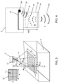
- Figure 1 is a schematic view of an aircraft fuel tank system comprising a fuel tank, and apparatus for measuring a surface 1 of fuel in the fuel tank.
- a time-of-flight camera 2 can view into the fuel tank through an optical access window 3 in a top wall 5 of the fuel tank, in a position where the wall 5 is not normally covered in fuel.
- the window 3 has hydrophobic coatings to minimise problems with condensation, fog, frost and microbial growth.
- the camera 2 can acquire and digitise images of a field of view 4. These images are transmitted to an acquisition and conditioning module 11 of an image acquisition and elaboration section 9 via an electrical harness 10.
- the fuel tank is shown schematically with a parallelepiped structure with front and rear walls, left and right side walls, a bottom wall and a top wall.
- the camera 2 is positioned centrally and pointed directly down towards the fuel surface 1.
- Figure 2 to the camera is positioned to one side of the tank and pointed towards the fuel surface 1 at an oblique angle.
- the wide field of view 4 of the camera creates image distortion.
- An image elaboration (correction) processor 12 applies a predetermined correction coefficient matrix to the images in order to correct for this distortion.
- the corrected images can then be output to a display device 15 for display to a pilot of the aircraft during flight of the aircraft, or to ground crew during refuel and ground operations.
- a measurement pulse 20 of visible light is sent from the camera 2 towards the fuel surface 1.
- the measurement pulse 20 is reflected and/or scattered by the fuel surface 1 and received by an array 21 of sensor pixels x j y k .
- Each sensor pixel of the array 21 of sensors measures a distance from a respective location of the fuel surface 1.
- a sensor pixel at position x j y k in the array 21 is shown measuring a distance D xj y k to a corresponding location on the fuel surface 1 which is also labelled x j y k . Knowing the distance of the camera 2 from the bottom 6 of the tank it is therefore possible to measure a fuel height h xj y k at the location x j y k .
- the same procedure can be applied to all other sensor pixels, and the fuel height for each point of the fuel surface 1 in the field of view of the camera 2 measured. This makes it possible to measure the quantity of fuel in the tank, knowing the tank geometry.
- the fuel heights can also be used to determine the attitude of the fuel surface 1, and/or to detect contaminants floating on the fuel surface.
- FIG 4 shows the camera 2 in detail.
- a light source 30 such as a laser generates pulses of light which are directed into a lens 31. Some of the light is transmitted through a semi-transparent window 32 to provide the measurement pulse 20 which illuminates the fuel surface 1. Some of the light is reflected by the window 32 to provide a reference pulse 33 which is directed onto the sensor array 21 by the lens 31 without having been reflected by the fuel.
- the window 32 is mounted in fixed relation to the sensor array 21 by a support 35 so that they are spaced apart by a known distance R/2 which does not vary in accordance with the quantity of the liquid in the fuel tank.
- the measurement pulse 20 travels to and from the fuel surface 1 via a measurement path 8 containing a transmission medium.
- This transmission medium is principally the air in an ullage 7 above the fuel surface 1.
- the distance of this measurement path varies in accordance with the quantity of fuel in the tank.
- the reference pulse 33 travels from the light source 30 to the sensor array 21 via a reference path having a known reference distance R which does not vary in accordance with the quantity of fuel in the tank.
- the space 34 between the lens 31 and the window 32 contains the same transmission medium as the measurement path (in this case the air in the ullage 7) at approximately the same temperature and pressure. This ensures that the reference path contains a transmission medium with substantially the same refractive index as the transmission medium in the measurement path, and hence substantially the same speed of light in the medium.
- the camera 2 determines a measured time of flight of the measurement pulse 20 via the measurement path for each sensor in the array. This time-of-flight measurement is dependent on the speed of light c in the measurement path, which varies in accordance with the refractive index of the transmission medium in the measurement path (as determined by its temperature, density and material composition).
- the camera 2 measures a reference time of flight of the reference pulse 33 via the reference path to at least one sensor pixel in the array 21, and corrects the estimate of the quantity of fuel in accordance with this reference time of flight.
- These fuel surface heights h xj y k are then used by the processor 14 to determine the attitude of the fuel surface 1 along with the quantity of fuel in the tank (mass and/or volume) based on the known geometry of the tank.
- Figure 5 is an alternative embodiment with an optical-fibre based image acquisition system in which the camera is located remotely.
- a light source 30a directs light into an optical fibre bundle 10a via eyepiece optics 16. The light is then directed into the fuel tank by a fibrescope 17. Reflected light is received by the fibrescope 17 which it transmits to a time-of-flight camera 2a via the optical fibre bundle 10a and eyepiece optics 16. In this case the reference path is integrated into the fibrescope 17 at the end of the optical fibre bundle 10a.
- Figure 6 is an alternative embodiment in which the camera's field of view 4 includes not only the surface 1 of the fuel but also two side walls of the fuel tank which meet at a corner. This enables the time-of-flight camera 2 to measure the height of the fuel surface 1, and also the height of the interface where the fuel surface 1 meets the two side walls.
- the camera 2 in Figure 6 may be replaced by a fibrescope 17 and remote camera 2a as in Figure 5 .
- a preset location 19 at the top of the field of view 4 where it meets the corner of the fuel tank can be used to provide a reference path with a relatively long known reference distance R, instead of using a relatively short reference path within the camera as shown in Figure 4 .
- This preset location 19 is at a known and fixed distance R/2 from the camera, and is imaged by one of the sensor pixels.
- the associated reference time of flight to and from that location 19 is used to determine the speed of light in the ullage.
- Figures 7a and 7b show an alternative embodiment in which the camera 2 is mounted to the bottom wall 6 of the fuel tank and views the fuel surface 1 from below through the liquid fuel.
- the space 34 between the lens 31 and window 32 in the camera which provides the reference path for measurement of the speed of light in the medium, is flooded with liquid fuel at approximately the same temperature as the fuel in the tank. This may be achieved by leaving an open passage through the support 35 and into the reference path, and immersing the camera 2 in the fuel so that fuel flows through the open passage and into the reference path.
- the reference path may be sealed and contain fuel of the same type that is in the fuel tank.
- a light source 30, 30a is arranged to illuminate a surface 1 of liquid fuel in the fuel tank with light so that the light is reflected or scattered by the surface 1 onto an array 21 of sensors.
- the light travels to and from the surface 1 via a measurement path containing a transmission medium (ullage gas or liquid fuel for example).
- the light source is also arranged to illuminate at least one sensor of the array 21 of sensor with light via a reference path containing a transmission medium with substantially the same refractive index as the transmission medium in the measurement path.
- the reference path has a known reference distance R which does not vary in accordance with the quantity of the fuel.
- a processing system is arranged to determine a measured time of flight t xj yk of the light which travels via the measurement path to each sensor of the array 21 of sensors.
- the processing system is also arranged to measure a reference time of flight t R of the light which travels via the reference path to said at least one sensor of the array 21 of sensors.
- the processing system estimates the quantity of the fuel in the fuel tank in accordance with the measured times of flight t xj yk , the reference time of flight t R and the known reference distance R.
- the processing system may be a single processing unit 14 or a more distributed processing system - some of the processing system being housed in the camera 2, 2a for example.
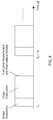
- a single measurement pulse is sent out and the reflected light is sensed at all pixels of the sensor array.
- the time-of-flight measurements are calculated and processed to provide an image of the field of view of the camera, and from that to determine a height and attitude of the fuel surface, and hence to estimate a quantity of the liquid fuel in the fuel tank.
- a calibration measurement of the speed of light c R in the transmission medium is made once per cycle. Each measurement of c R is used to correct the measured distance from the fuel surface (and hence estimate the quantity of liquid fuel) for that cycle.
- Figure 9 is a plan view of an aircraft 50 incorporating the system of Figure 1 .
- the aircraft has a wing fuel tank in each wing, and a centre fuel tank under the fuselage.
- Each fuel tank is divided into a number of bays, each bay being separate from an adjacent bay by a rib which has holes allowing fuel to move between the adjacent bays.
- Figure 9 shows two bays 51 of each wing fuel tank and a single bay 52 of the centre fuel tank.
- Each one of the five bays has a time-of-flight camera installed as shown in Figure 1 .
- each electrical harness 10 or optical fibre bundle 10a leads to a single centralised image elaboration and elaboration section 9 in a pressurised and conditioned area.
- Figure 10 shows an alternative localised architecture in which three image elaboration and elaboration sections 9 are provided closer to the bays thus reducing the length of electrical harness required.
- the elaborated data may be transferred to a central one of the sections 9 via an electrical or optical communication network 53.
- the time-of-flight camera 2 is a direct time-of-flight camera which measures the direct time-of-flight required for a laser pulse to leave the camera and reflect back onto the sensor array.
- the time-of-flight camera may use an RF-modulated light source and a phase detector.
- the outgoing beam is continuous (rather than pulsed) and modulated with an RF carrier, and the phase shift of that carrier is measured on the receiver side.
- the time-of-flight camera may be a range gated imager with a shutter in front of the sensor array that opens and closes at the same rate as the light pulses are sent out. Part of every returning pulse is blocked by the shutter according to its time of arrival, so the amount of light received relates to the time of flight.
Landscapes
- Physics & Mathematics (AREA)
- Electromagnetism (AREA)
- General Physics & Mathematics (AREA)
- Engineering & Computer Science (AREA)
- Fluid Mechanics (AREA)
- Thermal Sciences (AREA)
- Aviation & Aerospace Engineering (AREA)
- Computer Networks & Wireless Communication (AREA)
- Radar, Positioning & Navigation (AREA)
- Remote Sensing (AREA)
- Signal Processing (AREA)
- Measurement Of Levels Of Liquids Or Fluent Solid Materials (AREA)
- Length Measuring Devices By Optical Means (AREA)
Abstract
Description
- The present invention relates to a method of estimating a quantity of a liquid fuel in a fuel tank of an aircraft, and related apparatus.
-
US2015/0153212 discloses a method of measuring a height of a fuel surface of fuel in an aircraft fuel tank. One or more images of the fuel surface are captured, each image including a fuel surface line where the fuel surface meets a structure. Each image is analysed in order to determine a height of the fuel surface line at three or more points in the image. If the fuel surface line is not a straight line, then an average angle of the fuel surface line can be determined from the points in the image by spatial averaging. Preferably a series of images of the fuel surface are captured over a time period, and an average height of the fuel surface is determined from the series of images by time averaging. The height of the fuel surface line(s) at three or more points is used to determine a volume of the fuel, a mass of the fuel, and/or an attitude of the fuel surface. - A Time-of-Flight Camera (ToF Camera) is a range imaging camera system that resolves distance based on the known speed of light. A ToF Camera is based on the laser rangefinder principle: a very short laser pulse is sent against a target and the time-of-flight (i.e. the time the laser pulse takes to be reflected and to come back to the receiver) is measured. Knowing the speed of propagation of the light the distance can be resolved.
- A ToF Camera is a 3D version of a laser rangefinder, where the receiver is a matrix of pixels, and each pixel is able to measure the time-of-flight for the emitted light/laser pulse reflected by a specific region of a 3D object. The final result is a 3D map (or distance map) of the real 3D object. There are typically no moving parts within the ToF Camera and a 3D map of an object can be done in a single measurement. Acquisition rates of 50-60 Hz have been achieved with commercial systems.
- A 3-D imaging system is described in
WO2006/097406 . A photodiode or sensor cell are placed in an illumination unit. The sensor cell provides a phase reference essentially corresponding to a zero distance measurement. - A first aspect of the invention provides an aircraft fuel tank system comprising: a fuel tank; an array of sensors; a light source arranged to illuminate a surface of a liquid fuel in the fuel tank with light so that the light is reflected or scattered by the surface of the fuel onto an array of sensors, the light travelling to and from the surface of the fuel via a measurement path containing a transmission medium, wherein the light source is also arranged to illuminate at least one sensor of the array of sensors with light via a reference path containing a transmission medium with substantially the same refractive index as the transmission medium in the measurement path, the reference path having a known reference distance which does not vary in accordance with the quantity of the fuel; and a processing system arranged to determine a measured time of flight of the light which travels via the measurement path to each sensor of the array of sensors, measure a reference time of flight of the light which travels via the reference path to said at least one sensor, and estimate the quantity of the fuel in the fuel tank in accordance with the measured times of flight, the reference time of flight and the known reference distance.
- Thus, the light may be reflected or scattered by the surface of the fuel onto the array of sensors such that each sensor of the array of sensors receives reflected light from a respective location of a plurality of locations on the surface of the fuel, and the processing system may be arranged to determine a measured time of flight of the light which travels via the measurement path to each sensor of the array of sensors to thereby determine a measured time of flight for each respective location of the plurality of locations on the surface of the fuel.
- A further aspect of the invention provides a method of estimating a quantity of a liquid fuel in a fuel tank of an aircraft, the method comprising: illuminating a surface of the fuel with light so that the light is reflected or scattered by the surface of the fuel onto an array of sensors, the light travelling to and from the surface of the fuel via a measurement path containing a transmission medium; for each sensor of the array of sensors, determining a measured time of flight of the light which travels via the measurement path to that sensor; illuminating at least one sensor of the array of sensors with light via a reference path containing a transmission medium with substantially the same refractive index as the transmission medium in the measurement path, the reference path having a known reference distance which does not vary in accordance with the quantity of the fuel; measuring a reference time of flight of the light which travels via the reference path to said at least one sensor; and estimating the quantity of the fuel in the fuel tank in accordance with the measured times of flight, the reference time of flight and the known reference distance.
- The light may be in the visible, ultraviolet or infrared part of the spectrum.
- The light travelling via the reference path may be reflected or scattered onto said at least one sensor by a fixed structure such as a wall of the fuel tank. Optionally the system further comprises a reflector which is mounted in fixed relation to the array of sensors, so that the light travelling via the reference path is reflected onto said at least sensor by the reflector. The reflector may be a semi-transparent window arranged such that some of the light from the light source is transmitted through the semi-transparent window and illuminates the surface of the fuel, and some of the light from the light source is reflected by the window onto said at least one sensor.
- Optionally the light source is arranged for pulsed operation so that the light which illuminates the surface of the liquid fuel in the fuel tank is emitted by the light source in pulses. In this case the system may directly measure the time of flight, or may indirectly measure the time of flight by using a range gated imager with a shutter in front of the sensor array that opens and closes at the same rate as the light pulses are sent out. Part of every returning pulse is blocked by the shutter according to its time of arrival, so the amount of light received relates to the time of flight.
- Alternatively the light source may be arranged for continuous operation so that the light which illuminates the surface of the liquid fuel in the fuel tank is emitted continuously by the light source. For example the light may be modulated with an RF carrier, and the phase shift of that carrier measured at the sensor array to infer the time of flight.
- The surface of the fuel may be illuminated from above so that the transmission medium in the measurement path comprises ullage gas, or from below so that the transmission medium in the measurement path comprises the liquid fuel.
- Optionally a lens is arranged so that the light travelling to and from the surface of the fuel via the measurement path passes through the lens. The lens may be arranged so that the light travelling to said at least one sensor via the reference path also passes through the lens.
- Embodiments of the invention will now be described with reference to the accompanying drawings, in which:
-
Figure 1 shows an aircraft fuel tank and a time-of-flight based system for measuring a surface of fuel in the tank; -
Figure 2 shows an alternative field of view for the camera; -
Figure 3 shows the principle of operation of the camera; -
Figure 4 shows the camera in detail; -
Figure 5 shows an alternative system employing optical fibre; -
Figure 6 shows a system in which the field of view of the camera includes the fuel tank wall; -
Figures 7a and 7b show a system in which the camera views the fuel surface from below; -
Figure 8 shows a process for making a series of measurements; -
Figure 9 shows an aircraft with a centralised processing architecture for monitoring fuel; and -
Figure 10 shows an aircraft with a distributed processing architecture for monitoring fuel. -
Figure 1 is a schematic view of an aircraft fuel tank system comprising a fuel tank, and apparatus for measuring asurface 1 of fuel in the fuel tank. A time-of-flight camera 2 can view into the fuel tank through anoptical access window 3 in atop wall 5 of the fuel tank, in a position where thewall 5 is not normally covered in fuel. Thewindow 3 has hydrophobic coatings to minimise problems with condensation, fog, frost and microbial growth. Thecamera 2 can acquire and digitise images of a field ofview 4. These images are transmitted to an acquisition andconditioning module 11 of an image acquisition andelaboration section 9 via anelectrical harness 10. - The fuel tank is shown schematically with a parallelepiped structure with front and rear walls, left and right side walls, a bottom wall and a top wall. In
Figure 1 thecamera 2 is positioned centrally and pointed directly down towards thefuel surface 1. InFigure 2 to the camera is positioned to one side of the tank and pointed towards thefuel surface 1 at an oblique angle. - The wide field of
view 4 of the camera creates image distortion. An image elaboration (correction)processor 12 applies a predetermined correction coefficient matrix to the images in order to correct for this distortion. - The corrected images can then be output to a
display device 15 for display to a pilot of the aircraft during flight of the aircraft, or to ground crew during refuel and ground operations. - The operation of the
camera 2 is shown inFigures 3 and 4 . Ameasurement pulse 20 of visible light is sent from thecamera 2 towards thefuel surface 1. Themeasurement pulse 20 is reflected and/or scattered by thefuel surface 1 and received by anarray 21 of sensor pixels xj yk. Each sensor pixel of thearray 21 of sensors measures a distance from a respective location of thefuel surface 1. So inFigure 3 a sensor pixel at position xj yk in thearray 21 is shown measuring a distance Dxj yk to a corresponding location on thefuel surface 1 which is also labelled xj yk. Knowing the distance of thecamera 2 from thebottom 6 of the tank it is therefore possible to measure a fuel height hxj yk at the location xj yk. - The same procedure can be applied to all other sensor pixels, and the fuel height for each point of the
fuel surface 1 in the field of view of thecamera 2 measured. This makes it possible to measure the quantity of fuel in the tank, knowing the tank geometry. The fuel heights can also be used to determine the attitude of thefuel surface 1, and/or to detect contaminants floating on the fuel surface. - The distance Dxj yk can be measured applying the formula: Dxj yk = ctxj yk /2, where c is the speed of light in the measurement path (in this case the ullage above the fuel surface 1) and txj yk is the measured time-of-flight for the
measurement pulse 20 to be reflected from thefuel surface 1 at location xj yk and recorded by the sensor pixel xj yk. - The fuel heights hxj yk are then hxj yk = HToF - h'xj yk = HToF - Dxj yk · cos αjk where angle αjk is known from the optics of the
camera 2, distance HToF is the known distance from thearray 21 to thebottom 6 of the tank, and height h'xj yk is the height from the location xj yk on the fuel surface to thearray 21. -
Figure 4 shows thecamera 2 in detail. Alight source 30 such as a laser generates pulses of light which are directed into alens 31. Some of the light is transmitted through asemi-transparent window 32 to provide themeasurement pulse 20 which illuminates thefuel surface 1. Some of the light is reflected by thewindow 32 to provide areference pulse 33 which is directed onto thesensor array 21 by thelens 31 without having been reflected by the fuel. Thewindow 32 is mounted in fixed relation to thesensor array 21 by asupport 35 so that they are spaced apart by a known distance R/2 which does not vary in accordance with the quantity of the liquid in the fuel tank. - The
measurement pulse 20 travels to and from thefuel surface 1 via ameasurement path 8 containing a transmission medium. This transmission medium is principally the air in anullage 7 above thefuel surface 1. The distance of this measurement path varies in accordance with the quantity of fuel in the tank. Thereference pulse 33 on the other hand travels from thelight source 30 to thesensor array 21 via a reference path having a known reference distance R which does not vary in accordance with the quantity of fuel in the tank. Thespace 34 between thelens 31 and thewindow 32 contains the same transmission medium as the measurement path (in this case the air in the ullage 7) at approximately the same temperature and pressure. This ensures that the reference path contains a transmission medium with substantially the same refractive index as the transmission medium in the measurement path, and hence substantially the same speed of light in the medium. - As described above, the
camera 2 determines a measured time of flight of themeasurement pulse 20 via the measurement path for each sensor in the array. This time-of-flight measurement is dependent on the speed of light c in the measurement path, which varies in accordance with the refractive index of the transmission medium in the measurement path (as determined by its temperature, density and material composition). Thecamera 2 measures a reference time of flight of thereference pulse 33 via the reference path to at least one sensor pixel in thearray 21, and corrects the estimate of the quantity of fuel in accordance with this reference time of flight. Specifically, a speed of light cR is used to measure the time of flight to and from thefuel surface 1, where cR= R/tR, tR is the reference time of flight for thereference pulse 33, and R is the known reference distance. - An estimation of the fuel surface heights hxj yk at the various locations within the field of
view 4 are then determined by aprocessor 14 based on the algorithm previously mentioned: hxj yk= HToF - h'xj yk= HToF - Dxj yk · cos αjk. These fuel surface heights hxj yk are then used by theprocessor 14 to determine the attitude of thefuel surface 1 along with the quantity of fuel in the tank (mass and/or volume) based on the known geometry of the tank. -
Figure 5 is an alternative embodiment with an optical-fibre based image acquisition system in which the camera is located remotely. Alight source 30a directs light into anoptical fibre bundle 10a viaeyepiece optics 16. The light is then directed into the fuel tank by afibrescope 17. Reflected light is received by thefibrescope 17 which it transmits to a time-of-flight camera 2a via theoptical fibre bundle 10a andeyepiece optics 16. In this case the reference path is integrated into thefibrescope 17 at the end of theoptical fibre bundle 10a. -
Figure 6 is an alternative embodiment in which the camera's field ofview 4 includes not only thesurface 1 of the fuel but also two side walls of the fuel tank which meet at a corner. This enables the time-of-flight camera 2 to measure the height of thefuel surface 1, and also the height of the interface where thefuel surface 1 meets the two side walls. Thecamera 2 inFigure 6 may be replaced by afibrescope 17 andremote camera 2a as inFigure 5 . - A
preset location 19 at the top of the field ofview 4 where it meets the corner of the fuel tank can be used to provide a reference path with a relatively long known reference distance R, instead of using a relatively short reference path within the camera as shown inFigure 4 . Thispreset location 19 is at a known and fixed distance R/2 from the camera, and is imaged by one of the sensor pixels. The associated reference time of flight to and from thatlocation 19 is used to determine the speed of light in the ullage. -
Figures 7a and 7b show an alternative embodiment in which thecamera 2 is mounted to thebottom wall 6 of the fuel tank and views thefuel surface 1 from below through the liquid fuel. In this case thespace 34 between thelens 31 andwindow 32 in the camera, which provides the reference path for measurement of the speed of light in the medium, is flooded with liquid fuel at approximately the same temperature as the fuel in the tank. This may be achieved by leaving an open passage through thesupport 35 and into the reference path, and immersing thecamera 2 in the fuel so that fuel flows through the open passage and into the reference path. Alternatively the reference path may be sealed and contain fuel of the same type that is in the fuel tank. The algorithm to measure the fuel height is similar to the one described above, in this case: hxj yk= Dxj yk · cos αjk. - To summarize the embodiments of the invention described above, a
light source surface 1 of liquid fuel in the fuel tank with light so that the light is reflected or scattered by thesurface 1 onto anarray 21 of sensors. The light travels to and from thesurface 1 via a measurement path containing a transmission medium (ullage gas or liquid fuel for example). The light source is also arranged to illuminate at least one sensor of thearray 21 of sensor with light via a reference path containing a transmission medium with substantially the same refractive index as the transmission medium in the measurement path. The reference path has a known reference distance R which does not vary in accordance with the quantity of the fuel. A processing system is arranged to determine a measured time of flight txj yk of the light which travels via the measurement path to each sensor of thearray 21 of sensors. The processing system is also arranged to measure a reference time of flight tR of the light which travels via the reference path to said at least one sensor of thearray 21 of sensors. The processing system estimates the quantity of the fuel in the fuel tank in accordance with the measured times of flight txj yk, the reference time of flight tR and the known reference distance R. More specifically, distances Dxj yk are determined in accordance with the measured times of flight txj yk, the reference time of flight tR and the known reference distance R as: Dxj yk = R.txj yk /2.tR. These distances Dxj yk are used to determine heights of the fuel surface hxj yk= HToF - h'xj yk= HToF - Dxj yk · cos αjk. The heights hxj yk of thefuel surface 1 are used to estimate the quantity of the fuel in the fuel tank based on the known geometry of the tank. The processing system may be asingle processing unit 14 or a more distributed processing system - some of the processing system being housed in thecamera - The image acquisition and elaboration must be performed in real-time to allow a refresh time of the fuel quantity indication of Is (1 Hz refresh rate) minimum as illustrated in
Figure 8 . To allow this, a Digital Signal Processor (DSP) or similar high performance processors might be used forelements Figure 1 .Figure 8 shows two measurement cycles spaced apart by Is. - During the image acquisition phase of each cycle, a single measurement pulse is sent out and the reflected light is sensed at all pixels of the sensor array. During an image elaboration phase of each cycle the time-of-flight measurements are calculated and processed to provide an image of the field of view of the camera, and from that to determine a height and attitude of the fuel surface, and hence to estimate a quantity of the liquid fuel in the fuel tank. A calibration measurement of the speed of light cR in the transmission medium is made once per cycle. Each measurement of cR is used to correct the measured distance from the fuel surface (and hence estimate the quantity of liquid fuel) for that cycle.
-
Figure 9 is a plan view of anaircraft 50 incorporating the system ofFigure 1 . The aircraft has a wing fuel tank in each wing, and a centre fuel tank under the fuselage. Each fuel tank is divided into a number of bays, each bay being separate from an adjacent bay by a rib which has holes allowing fuel to move between the adjacent bays.Figure 9 shows twobays 51 of each wing fuel tank and asingle bay 52 of the centre fuel tank. Each one of the five bays has a time-of-flight camera installed as shown inFigure 1 . In the architecture ofFigure 9 eachelectrical harness 10 oroptical fibre bundle 10a leads to a single centralised image elaboration andelaboration section 9 in a pressurised and conditioned area. -
Figure 10 shows an alternative localised architecture in which three image elaboration andelaboration sections 9 are provided closer to the bays thus reducing the length of electrical harness required. The elaborated data may be transferred to a central one of thesections 9 via an electrical oroptical communication network 53. - In the embodiments described above, the time-of-
flight camera 2 is a direct time-of-flight camera which measures the direct time-of-flight required for a laser pulse to leave the camera and reflect back onto the sensor array. In other embodiments of the invention, other forms of time-of-flight camera may be used. For example the time-of-flight camera may use an RF-modulated light source and a phase detector. The outgoing beam is continuous (rather than pulsed) and modulated with an RF carrier, and the phase shift of that carrier is measured on the receiver side. Alternatively the time-of-flight camera may be a range gated imager with a shutter in front of the sensor array that opens and closes at the same rate as the light pulses are sent out. Part of every returning pulse is blocked by the shutter according to its time of arrival, so the amount of light received relates to the time of flight. - Although the invention has been described above with reference to one or more preferred embodiments, it will be appreciated that various changes or modifications may be made without departing from the scope of the invention as defined in the appended claims.
Claims (11)
- An aircraft fuel tank system comprising: a fuel tank; an array of sensors; a light source arranged to illuminate a surface of a liquid fuel in the fuel tank with light so that the light is reflected or scattered by the surface of the fuel onto the array of sensors, the light travelling to and from the surface of the fuel via a measurement path containing a transmission medium, wherein the light source is also arranged to illuminate at least one sensor of the array of sensors with light via a reference path containing a transmission medium with substantially the same refractive index as the transmission medium in the measurement path, the reference path having a known reference distance which does not vary in accordance with the quantity of the fuel; and a processing system arranged to determine a measured time of flight of the light which travels via the measurement path to each sensor of the array of sensors, measure a reference time of flight of the light which travels via the reference path to said at least one sensor, and estimate the quantity of the fuel in the fuel tank in accordance with the measured times of flight, the reference time of flight and the known reference distance.
- A system according to claim 1 further comprising a reflector which is mounted in fixed relation to the array of sensors, so that the light travelling via the reference path is reflected onto said at least one sensor by the reflector.
- A system according to claim 2 wherein the reflector is a semi-transparent window arranged such that some of the light from the light source is transmitted through the semi-transparent window and illuminates the surface of the fuel to provide the measurement path, and some of the light from the light source is reflected by the semi-transparent window onto said at least one sensor to provide the reference path.
- A system according to any preceding claim wherein the light source is arranged for pulsed operation so that the light which illuminates the surface of the liquid fuel in the fuel tank is emitted by the light source in pulses.
- A system according to any preceding claim wherein the surface of the fuel is illuminated from above so that the transmission medium in the measurement path comprises ullage gas.
- A system according to any preceding claim wherein the surface of the fuel is illuminated from below so that the transmission medium in the measurement path comprises the liquid fuel.
- A system according to any preceding claim further comprising a lens arranged so that the light travelling to and from the surface of the fuel via the measurement path passes through the lens.
- A system according to claim 7 wherein the lens is arranged so that the light travelling to said at least one sensor via the reference path also passes through the lens.
- A system according to any preceding claim wherein the processing system is arranged to estimate the quantity of the fuel in the fuel tank in accordance with the measured times of flight, the reference time of flight, the known reference distance, and a known geometry of the fuel tank.
- An aircraft comprising a fuel tank system according to any preceding claim.
- A method of estimating a quantity of a liquid fuel in a fuel tank of an aircraft, the method comprising: illuminating a surface of the fuel with light so that the light is reflected or scattered by the surface of the fuel onto an array of sensors, the light travelling to and from the surface of the fuel via a measurement path containing a transmission medium; for each sensor of the array of sensors, determining a measured time of flight of the light which travels via the measurement path to that sensor; illuminating at least one sensor of the array of sensors with light via a reference path containing a transmission medium with substantially the same refractive index as the transmission medium in the measurement path, the reference path having a known reference distance which does not vary in accordance with the quantity of the fuel; measuring a reference time of flight of the light which travels via the reference path to said at least one sensor; and estimating the quantity of the fuel in the fuel tank in accordance with the measured times of flight, the reference time of flight and the known reference distance.
Applications Claiming Priority (1)
| Application Number | Priority Date | Filing Date | Title |
|---|---|---|---|
| GB1511452.3A GB2539909A (en) | 2015-06-30 | 2015-06-30 | Aircraft fuel measurement |
Publications (2)
| Publication Number | Publication Date |
|---|---|
| EP3112822A1 true EP3112822A1 (en) | 2017-01-04 |
| EP3112822B1 EP3112822B1 (en) | 2021-05-05 |
Family
ID=53872436
Family Applications (1)
| Application Number | Title | Priority Date | Filing Date |
|---|---|---|---|
| EP16173251.6A Active EP3112822B1 (en) | 2015-06-30 | 2016-06-07 | Aircraft fuel measurement |
Country Status (4)
| Country | Link |
|---|---|
| US (1) | US10480986B2 (en) |
| EP (1) | EP3112822B1 (en) |
| CN (1) | CN106323418B (en) |
| GB (1) | GB2539909A (en) |
Cited By (2)
| Publication number | Priority date | Publication date | Assignee | Title |
|---|---|---|---|---|
| WO2018146423A1 (en) * | 2017-02-10 | 2018-08-16 | Safran Electrical & Power | Optical probe for measuring the level of a liquid in a tank |
| EP3722757A1 (en) * | 2019-04-10 | 2020-10-14 | The Boeing Company | Non-contact time-of-flight fuel level sensor using plastic optical fiber |
Families Citing this family (16)
| Publication number | Priority date | Publication date | Assignee | Title |
|---|---|---|---|---|
| US10326980B2 (en) | 2016-02-04 | 2019-06-18 | Simmonds Precision Products, Inc. | Imaging system for fuel tank analysis |
| US10424076B2 (en) | 2016-02-04 | 2019-09-24 | Simmonds Precision Products, Inc. | Imaging system for fuel tank analysis |
| GB2554751A (en) | 2016-10-10 | 2018-04-11 | Airbus Operations Ltd | Measuring fuel in a fuel tank |
| CN107796488B (en) * | 2017-11-16 | 2019-12-24 | 西安交通大学 | A liquid level sloshing test bench based on a motion platform and an ultrasonic liquid level sensor |
| DE102018200363B3 (en) * | 2018-01-11 | 2019-03-21 | Robert Bosch Gmbh | Measuring device for level monitoring and differential measurement of the optical refractive index |
| DE102018102366A1 (en) * | 2018-02-02 | 2019-08-08 | Endress+Hauser SE+Co. KG | level meter |
| WO2020180673A1 (en) * | 2019-03-01 | 2020-09-10 | Zodiac Cabin Controls Gmbh | Universal liquid level sensing |
| CN110646052A (en) * | 2019-09-30 | 2020-01-03 | 李宝婕 | Method and device for accurately detecting residual oil quantity of oil tank in fuel-driven moving body |
| CN111103633A (en) * | 2019-12-31 | 2020-05-05 | 联想(北京)有限公司 | Control method of electronic equipment and electronic equipment |
| FR3138209B1 (en) * | 2022-07-22 | 2024-07-12 | Safran | Optical liquid level measurement system |
| CN116295717B (en) * | 2023-02-16 | 2026-03-20 | 成都阜时科技有限公司 | A method for measuring liquid level in a container based on DTOF, a DTOF module and the container |
| CN116754048A (en) * | 2023-05-25 | 2023-09-15 | 中国航空工业集团公司金城南京机电液压工程研究中心 | An aircraft fuel measurement system based on visual sensors |
| US12623673B2 (en) | 2023-06-29 | 2026-05-12 | Torc Robotics, Inc. | Systems and methods of detecting fluid release |
| US12626545B2 (en) | 2023-06-29 | 2026-05-12 | Torc Robotics, Inc. | Systems and methods of detecting fluid release |
| US12546269B2 (en) * | 2023-06-30 | 2026-02-10 | Torc Robotics, Inc. | Systems and methods of detecting fluid release |
| CN117238056B (en) * | 2023-09-15 | 2026-04-14 | 四川沃飞长空科技发展有限公司 | Pilot behavior detection method and system and aircraft |
Citations (5)
| Publication number | Priority date | Publication date | Assignee | Title |
|---|---|---|---|---|
| WO1983003135A1 (en) * | 1982-03-04 | 1983-09-15 | Jackson, David, Alfred | Fluid level sensing apparatus |
| US4692023A (en) * | 1983-07-30 | 1987-09-08 | Tokyo Kagaku Kikai Kabushiki Kaisha | Optical adapter for a light-wave rangefinder |
| WO2006097406A2 (en) | 2005-03-17 | 2006-09-21 | Iee International Electronics & Engineering S.A. | 3-d imaging system |
| EP2770308A1 (en) * | 2013-02-26 | 2014-08-27 | Sick Ag | Optoelectronic fill level sensor |
| US20150153212A1 (en) | 2013-11-29 | 2015-06-04 | Airbus Operations Limited | Fuel surface height measurement |
Family Cites Families (22)
| Publication number | Priority date | Publication date | Assignee | Title |
|---|---|---|---|---|
| JPS55146015A (en) * | 1979-05-02 | 1980-11-14 | Ebara Corp | Non-contact measuring method for surface level and its measuring unit |
| US4524282A (en) | 1982-06-24 | 1985-06-18 | Courser, Incorporated | Electro-optical level detector |
| DE3706453A1 (en) * | 1987-02-27 | 1988-09-08 | Bayerische Motoren Werke Ag | Liquid-level signal transmitter for motor vehicles |
| JP3134218B2 (en) * | 1996-03-19 | 2001-02-13 | 株式会社オプトテクノ | Liquid detector |
| JPH11304567A (en) * | 1998-04-24 | 1999-11-05 | Rohm Co Ltd | Cleaning liquid inspecting device of cleaning device |
| US6782122B1 (en) | 2000-04-27 | 2004-08-24 | Simmonds Precision Products, Inc. | Apparatus for measuring height of a liquid in a container using area image pattern recognition techniques |
| GB0113611D0 (en) | 2001-05-30 | 2001-07-25 | Smiths Industries Plc | Fluid-gauging systems and methods |
| US8384538B2 (en) | 2002-06-11 | 2013-02-26 | Intelligent Technologies International, Inc. | Remote monitoring of fixed structures |
| US6759977B1 (en) | 2002-12-20 | 2004-07-06 | Saab Marine Electronics Ab | Method and apparatus for radar-based level gauging |
| US20080100501A1 (en) | 2006-10-26 | 2008-05-01 | Olov Edvardsson | Antenna for a radar level gauge |
| US8159660B2 (en) * | 2008-04-04 | 2012-04-17 | Leddartech Inc. | Optical level measurement device and method |
| US8184848B2 (en) | 2009-06-17 | 2012-05-22 | National Applied Research Laboratories | Liquid level detection method |
| EP2275833A1 (en) | 2009-07-01 | 2011-01-19 | IEE International Electronics & Engineering S.A.R.L. | Range camera and range image acquisition method |
| US8587771B2 (en) * | 2010-07-16 | 2013-11-19 | Microsoft Corporation | Method and system for multi-phase dynamic calibration of three-dimensional (3D) sensors in a time-of-flight system |
| DE102010062108A1 (en) | 2010-11-29 | 2012-05-31 | Robert Bosch Gmbh | Method for determining inclination of surface of liquid relative to container of e.g. vehicle, involves measuring distance of points of detection device to surface of liquid or granular material in container by using radar beams |
| EP2546600B1 (en) * | 2011-07-11 | 2014-07-30 | LayTec AG | Method and apparatus for real-time determination of spherical and non-spherical curvature of a surface |
| JP2013124962A (en) * | 2011-12-15 | 2013-06-24 | Disco Abrasive Syst Ltd | Liquid detector |
| US8817258B2 (en) * | 2012-05-21 | 2014-08-26 | Common Sensing Inc. | Dose measurement system and method |
| EP2932252A1 (en) * | 2012-12-14 | 2015-10-21 | Continental Automotive GmbH | Method for measuring ultrasonically the fill level of a liquid |
| WO2014208018A1 (en) * | 2013-06-26 | 2014-12-31 | パナソニックIpマネジメント株式会社 | Distance measuring system |
| US10063844B2 (en) * | 2013-10-17 | 2018-08-28 | Microsoft Technology Licensing, Llc. | Determining distances by probabilistic time of flight imaging |
| US9921150B2 (en) * | 2016-02-04 | 2018-03-20 | Simmonds Precision Products, Inc. | Imaging system for fuel tank analysis |
-
2015
- 2015-06-30 GB GB1511452.3A patent/GB2539909A/en not_active Withdrawn
-
2016
- 2016-06-07 EP EP16173251.6A patent/EP3112822B1/en active Active
- 2016-06-22 US US15/189,511 patent/US10480986B2/en active Active
- 2016-06-22 CN CN201610460784.5A patent/CN106323418B/en active Active
Patent Citations (5)
| Publication number | Priority date | Publication date | Assignee | Title |
|---|---|---|---|---|
| WO1983003135A1 (en) * | 1982-03-04 | 1983-09-15 | Jackson, David, Alfred | Fluid level sensing apparatus |
| US4692023A (en) * | 1983-07-30 | 1987-09-08 | Tokyo Kagaku Kikai Kabushiki Kaisha | Optical adapter for a light-wave rangefinder |
| WO2006097406A2 (en) | 2005-03-17 | 2006-09-21 | Iee International Electronics & Engineering S.A. | 3-d imaging system |
| EP2770308A1 (en) * | 2013-02-26 | 2014-08-27 | Sick Ag | Optoelectronic fill level sensor |
| US20150153212A1 (en) | 2013-11-29 | 2015-06-04 | Airbus Operations Limited | Fuel surface height measurement |
Cited By (5)
| Publication number | Priority date | Publication date | Assignee | Title |
|---|---|---|---|---|
| WO2018146423A1 (en) * | 2017-02-10 | 2018-08-16 | Safran Electrical & Power | Optical probe for measuring the level of a liquid in a tank |
| FR3062907A1 (en) * | 2017-02-10 | 2018-08-17 | Safran Electrical & Power | OPTICAL PROBE FOR MEASURING THE LEVEL OF A LIQUID IN A RESERVOIR |
| US11326927B2 (en) | 2017-02-10 | 2022-05-10 | Safran Electrical & Power | Optical probe for measuring the level of a liquid in a tank |
| EP3722757A1 (en) * | 2019-04-10 | 2020-10-14 | The Boeing Company | Non-contact time-of-flight fuel level sensor using plastic optical fiber |
| US10935413B2 (en) | 2019-04-10 | 2021-03-02 | The Boeing Company | Non-contact time-of-flight fuel level sensor using plastic optical fiber |
Also Published As
| Publication number | Publication date |
|---|---|
| EP3112822B1 (en) | 2021-05-05 |
| CN106323418A (en) | 2017-01-11 |
| GB201511452D0 (en) | 2015-08-12 |
| CN106323418B (en) | 2020-11-24 |
| GB2539909A (en) | 2017-01-04 |
| US20170003157A1 (en) | 2017-01-05 |
| US10480986B2 (en) | 2019-11-19 |
Similar Documents
| Publication | Publication Date | Title |
|---|---|---|
| US10480986B2 (en) | Aircraft fuel measurement | |
| CN106168503B (en) | Measuring the surface of a liquid | |
| EP4479722B1 (en) | Measurement of gas flow rate | |
| US20150153212A1 (en) | Fuel surface height measurement | |
| US8184276B2 (en) | Continuous index of refraction compensation method for measurements in a medium | |
| US10180327B1 (en) | Methods and apparatus for navigational aiding using celestial object tracking | |
| CA3029626A1 (en) | Optical air data systems and methods | |
| US10551237B2 (en) | Measuring fuel in a fuel tank | |
| KR101419407B1 (en) | System and method for measuring snowfall using optical device | |
| US11204424B2 (en) | Method for capturing a 3D scene by means of a LIDAR system and a LIDAR system for this purpose | |
| US11874379B2 (en) | Time-resolved contrast imaging for lidar | |
| CA2948754C (en) | Imaging system for fuel tank analysis | |
| EP0597715A1 (en) | Automatic aircraft landing system calibration | |
| CN113218512A (en) | Infrared thermometer capable of accurately aiming | |
| Amzajerdian et al. | Utilization of 3D imaging flash lidar technology for autonomous safe landing on planetary bodies | |
| EP2957100B1 (en) | Short-wave infrared based scope | |
| EP3015839A1 (en) | Laser pointing system for monitoring stability of structures | |
| CN104359810B (en) | A kind of long distance wireless PM2.5 concentration detection apparatus | |
| KR101957662B1 (en) | Apparatus for calculating target information, method thereof and flight control system comprising the same | |
| EP3825725A1 (en) | Distance testing arrangement for a lidar system, lidar system arrangement, and apparatus | |
| CN118946792B (en) | Measuring gas flow rate | |
| WO1992015839A1 (en) | Apparatus and method for measuring deviation of a reference point from a datum | |
| US7586584B2 (en) | Determination of range to a coherent light source using laser speckle pattern | |
| EP1810051B1 (en) | Determination of range to a coherent light source using laser speckle pattern | |
| Yang et al. | Study on the Testing System of Far-Field Laser Energy Density Distribution |
Legal Events
| Date | Code | Title | Description |
|---|---|---|---|
| PUAI | Public reference made under article 153(3) epc to a published international application that has entered the european phase |
Free format text: ORIGINAL CODE: 0009012 |
|
| STAA | Information on the status of an ep patent application or granted ep patent |
Free format text: STATUS: THE APPLICATION HAS BEEN PUBLISHED |
|
| AK | Designated contracting states |
Kind code of ref document: A1 Designated state(s): AL AT BE BG CH CY CZ DE DK EE ES FI FR GB GR HR HU IE IS IT LI LT LU LV MC MK MT NL NO PL PT RO RS SE SI SK SM TR |
|
| AX | Request for extension of the european patent |
Extension state: BA ME |
|
| STAA | Information on the status of an ep patent application or granted ep patent |
Free format text: STATUS: REQUEST FOR EXAMINATION WAS MADE |
|
| 17P | Request for examination filed |
Effective date: 20170322 |
|
| RBV | Designated contracting states (corrected) |
Designated state(s): AL AT BE BG CH CY CZ DE DK EE ES FI FR GB GR HR HU IE IS IT LI LT LU LV MC MK MT NL NO PL PT RO RS SE SI SK SM TR |
|
| STAA | Information on the status of an ep patent application or granted ep patent |
Free format text: STATUS: EXAMINATION IS IN PROGRESS |
|
| 17Q | First examination report despatched |
Effective date: 20180430 |
|
| REG | Reference to a national code |
Ref country code: DE Ref legal event code: R079 Ref document number: 602016057243 Country of ref document: DE Free format text: PREVIOUS MAIN CLASS: G01F0023292000 Ipc: G01F0023000000 |
|
| GRAP | Despatch of communication of intention to grant a patent |
Free format text: ORIGINAL CODE: EPIDOSNIGR1 |
|
| STAA | Information on the status of an ep patent application or granted ep patent |
Free format text: STATUS: GRANT OF PATENT IS INTENDED |
|
| RIC1 | Information provided on ipc code assigned before grant |
Ipc: G01F 23/292 20060101ALI20200609BHEP Ipc: G01F 23/00 20060101AFI20200609BHEP |
|
| INTG | Intention to grant announced |
Effective date: 20200630 |
|
| GRAJ | Information related to disapproval of communication of intention to grant by the applicant or resumption of examination proceedings by the epo deleted |
Free format text: ORIGINAL CODE: EPIDOSDIGR1 |
|
| STAA | Information on the status of an ep patent application or granted ep patent |
Free format text: STATUS: EXAMINATION IS IN PROGRESS |
|
| INTC | Intention to grant announced (deleted) | ||
| GRAP | Despatch of communication of intention to grant a patent |
Free format text: ORIGINAL CODE: EPIDOSNIGR1 |
|
| STAA | Information on the status of an ep patent application or granted ep patent |
Free format text: STATUS: GRANT OF PATENT IS INTENDED |
|
| INTG | Intention to grant announced |
Effective date: 20201210 |
|
| GRAS | Grant fee paid |
Free format text: ORIGINAL CODE: EPIDOSNIGR3 |
|
| GRAA | (expected) grant |
Free format text: ORIGINAL CODE: 0009210 |
|
| STAA | Information on the status of an ep patent application or granted ep patent |
Free format text: STATUS: THE PATENT HAS BEEN GRANTED |
|
| AK | Designated contracting states |
Kind code of ref document: B1 Designated state(s): AL AT BE BG CH CY CZ DE DK EE ES FI FR GB GR HR HU IE IS IT LI LT LU LV MC MK MT NL NO PL PT RO RS SE SI SK SM TR |
|
| REG | Reference to a national code |
Ref country code: GB Ref legal event code: FG4D |
|
| REG | Reference to a national code |
Ref country code: CH Ref legal event code: EP |
|
| REG | Reference to a national code |
Ref country code: AT Ref legal event code: REF Ref document number: 1390372 Country of ref document: AT Kind code of ref document: T Effective date: 20210515 |
|
| REG | Reference to a national code |
Ref country code: IE Ref legal event code: FG4D |
|
| REG | Reference to a national code |
Ref country code: DE Ref legal event code: R096 Ref document number: 602016057243 Country of ref document: DE |
|
| REG | Reference to a national code |
Ref country code: LT Ref legal event code: MG9D |
|
| REG | Reference to a national code |
Ref country code: AT Ref legal event code: MK05 Ref document number: 1390372 Country of ref document: AT Kind code of ref document: T Effective date: 20210505 |
|
| PG25 | Lapsed in a contracting state [announced via postgrant information from national office to epo] |
Ref country code: BG Free format text: LAPSE BECAUSE OF FAILURE TO SUBMIT A TRANSLATION OF THE DESCRIPTION OR TO PAY THE FEE WITHIN THE PRESCRIBED TIME-LIMIT Effective date: 20210805 Ref country code: AT Free format text: LAPSE BECAUSE OF FAILURE TO SUBMIT A TRANSLATION OF THE DESCRIPTION OR TO PAY THE FEE WITHIN THE PRESCRIBED TIME-LIMIT Effective date: 20210505 Ref country code: HR Free format text: LAPSE BECAUSE OF FAILURE TO SUBMIT A TRANSLATION OF THE DESCRIPTION OR TO PAY THE FEE WITHIN THE PRESCRIBED TIME-LIMIT Effective date: 20210505 Ref country code: FI Free format text: LAPSE BECAUSE OF FAILURE TO SUBMIT A TRANSLATION OF THE DESCRIPTION OR TO PAY THE FEE WITHIN THE PRESCRIBED TIME-LIMIT Effective date: 20210505 Ref country code: LT Free format text: LAPSE BECAUSE OF FAILURE TO SUBMIT A TRANSLATION OF THE DESCRIPTION OR TO PAY THE FEE WITHIN THE PRESCRIBED TIME-LIMIT Effective date: 20210505 |
|
| PG25 | Lapsed in a contracting state [announced via postgrant information from national office to epo] |
Ref country code: RS Free format text: LAPSE BECAUSE OF FAILURE TO SUBMIT A TRANSLATION OF THE DESCRIPTION OR TO PAY THE FEE WITHIN THE PRESCRIBED TIME-LIMIT Effective date: 20210505 Ref country code: SE Free format text: LAPSE BECAUSE OF FAILURE TO SUBMIT A TRANSLATION OF THE DESCRIPTION OR TO PAY THE FEE WITHIN THE PRESCRIBED TIME-LIMIT Effective date: 20210505 Ref country code: NO Free format text: LAPSE BECAUSE OF FAILURE TO SUBMIT A TRANSLATION OF THE DESCRIPTION OR TO PAY THE FEE WITHIN THE PRESCRIBED TIME-LIMIT Effective date: 20210805 Ref country code: PT Free format text: LAPSE BECAUSE OF FAILURE TO SUBMIT A TRANSLATION OF THE DESCRIPTION OR TO PAY THE FEE WITHIN THE PRESCRIBED TIME-LIMIT Effective date: 20210906 Ref country code: PL Free format text: LAPSE BECAUSE OF FAILURE TO SUBMIT A TRANSLATION OF THE DESCRIPTION OR TO PAY THE FEE WITHIN THE PRESCRIBED TIME-LIMIT Effective date: 20210505 Ref country code: ES Free format text: LAPSE BECAUSE OF FAILURE TO SUBMIT A TRANSLATION OF THE DESCRIPTION OR TO PAY THE FEE WITHIN THE PRESCRIBED TIME-LIMIT Effective date: 20210505 Ref country code: IS Free format text: LAPSE BECAUSE OF FAILURE TO SUBMIT A TRANSLATION OF THE DESCRIPTION OR TO PAY THE FEE WITHIN THE PRESCRIBED TIME-LIMIT Effective date: 20210905 Ref country code: LV Free format text: LAPSE BECAUSE OF FAILURE TO SUBMIT A TRANSLATION OF THE DESCRIPTION OR TO PAY THE FEE WITHIN THE PRESCRIBED TIME-LIMIT Effective date: 20210505 Ref country code: GR Free format text: LAPSE BECAUSE OF FAILURE TO SUBMIT A TRANSLATION OF THE DESCRIPTION OR TO PAY THE FEE WITHIN THE PRESCRIBED TIME-LIMIT Effective date: 20210806 |
|
| REG | Reference to a national code |
Ref country code: NL Ref legal event code: MP Effective date: 20210505 |
|
| PG25 | Lapsed in a contracting state [announced via postgrant information from national office to epo] |
Ref country code: NL Free format text: LAPSE BECAUSE OF FAILURE TO SUBMIT A TRANSLATION OF THE DESCRIPTION OR TO PAY THE FEE WITHIN THE PRESCRIBED TIME-LIMIT Effective date: 20210505 |
|
| REG | Reference to a national code |
Ref country code: DE Ref legal event code: R119 Ref document number: 602016057243 Country of ref document: DE |
|
| PG25 | Lapsed in a contracting state [announced via postgrant information from national office to epo] |
Ref country code: RO Free format text: LAPSE BECAUSE OF FAILURE TO SUBMIT A TRANSLATION OF THE DESCRIPTION OR TO PAY THE FEE WITHIN THE PRESCRIBED TIME-LIMIT Effective date: 20210505 Ref country code: SM Free format text: LAPSE BECAUSE OF FAILURE TO SUBMIT A TRANSLATION OF THE DESCRIPTION OR TO PAY THE FEE WITHIN THE PRESCRIBED TIME-LIMIT Effective date: 20210505 Ref country code: SK Free format text: LAPSE BECAUSE OF FAILURE TO SUBMIT A TRANSLATION OF THE DESCRIPTION OR TO PAY THE FEE WITHIN THE PRESCRIBED TIME-LIMIT Effective date: 20210505 Ref country code: DK Free format text: LAPSE BECAUSE OF FAILURE TO SUBMIT A TRANSLATION OF THE DESCRIPTION OR TO PAY THE FEE WITHIN THE PRESCRIBED TIME-LIMIT Effective date: 20210505 Ref country code: CZ Free format text: LAPSE BECAUSE OF FAILURE TO SUBMIT A TRANSLATION OF THE DESCRIPTION OR TO PAY THE FEE WITHIN THE PRESCRIBED TIME-LIMIT Effective date: 20210505 Ref country code: EE Free format text: LAPSE BECAUSE OF FAILURE TO SUBMIT A TRANSLATION OF THE DESCRIPTION OR TO PAY THE FEE WITHIN THE PRESCRIBED TIME-LIMIT Effective date: 20210505 |
|
| REG | Reference to a national code |
Ref country code: CH Ref legal event code: PL |
|
| REG | Reference to a national code |
Ref country code: BE Ref legal event code: MM Effective date: 20210630 |
|
| PLBE | No opposition filed within time limit |
Free format text: ORIGINAL CODE: 0009261 |
|
| STAA | Information on the status of an ep patent application or granted ep patent |
Free format text: STATUS: NO OPPOSITION FILED WITHIN TIME LIMIT |
|
| PG25 | Lapsed in a contracting state [announced via postgrant information from national office to epo] |
Ref country code: MC Free format text: LAPSE BECAUSE OF FAILURE TO SUBMIT A TRANSLATION OF THE DESCRIPTION OR TO PAY THE FEE WITHIN THE PRESCRIBED TIME-LIMIT Effective date: 20210505 Ref country code: LU Free format text: LAPSE BECAUSE OF NON-PAYMENT OF DUE FEES Effective date: 20210607 |
|
| 26N | No opposition filed |
Effective date: 20220208 |
|
| PG25 | Lapsed in a contracting state [announced via postgrant information from national office to epo] |
Ref country code: LI Free format text: LAPSE BECAUSE OF NON-PAYMENT OF DUE FEES Effective date: 20210630 Ref country code: IE Free format text: LAPSE BECAUSE OF NON-PAYMENT OF DUE FEES Effective date: 20210607 Ref country code: DE Free format text: LAPSE BECAUSE OF NON-PAYMENT OF DUE FEES Effective date: 20220101 Ref country code: CH Free format text: LAPSE BECAUSE OF NON-PAYMENT OF DUE FEES Effective date: 20210630 |
|
| PG25 | Lapsed in a contracting state [announced via postgrant information from national office to epo] |
Ref country code: IS Free format text: LAPSE BECAUSE OF FAILURE TO SUBMIT A TRANSLATION OF THE DESCRIPTION OR TO PAY THE FEE WITHIN THE PRESCRIBED TIME-LIMIT Effective date: 20210905 Ref country code: AL Free format text: LAPSE BECAUSE OF FAILURE TO SUBMIT A TRANSLATION OF THE DESCRIPTION OR TO PAY THE FEE WITHIN THE PRESCRIBED TIME-LIMIT Effective date: 20210505 Ref country code: FR Free format text: LAPSE BECAUSE OF NON-PAYMENT OF DUE FEES Effective date: 20210705 |
|
| PG25 | Lapsed in a contracting state [announced via postgrant information from national office to epo] |
Ref country code: IT Free format text: LAPSE BECAUSE OF FAILURE TO SUBMIT A TRANSLATION OF THE DESCRIPTION OR TO PAY THE FEE WITHIN THE PRESCRIBED TIME-LIMIT Effective date: 20210505 Ref country code: BE Free format text: LAPSE BECAUSE OF NON-PAYMENT OF DUE FEES Effective date: 20210630 |
|
| PG25 | Lapsed in a contracting state [announced via postgrant information from national office to epo] |
Ref country code: HU Free format text: LAPSE BECAUSE OF FAILURE TO SUBMIT A TRANSLATION OF THE DESCRIPTION OR TO PAY THE FEE WITHIN THE PRESCRIBED TIME-LIMIT; INVALID AB INITIO Effective date: 20160607 |
|
| PG25 | Lapsed in a contracting state [announced via postgrant information from national office to epo] |
Ref country code: CY Free format text: LAPSE BECAUSE OF FAILURE TO SUBMIT A TRANSLATION OF THE DESCRIPTION OR TO PAY THE FEE WITHIN THE PRESCRIBED TIME-LIMIT Effective date: 20210505 |
|
| PG25 | Lapsed in a contracting state [announced via postgrant information from national office to epo] |
Ref country code: MK Free format text: LAPSE BECAUSE OF FAILURE TO SUBMIT A TRANSLATION OF THE DESCRIPTION OR TO PAY THE FEE WITHIN THE PRESCRIBED TIME-LIMIT Effective date: 20210505 |
|
| PG25 | Lapsed in a contracting state [announced via postgrant information from national office to epo] |
Ref country code: MT Free format text: LAPSE BECAUSE OF FAILURE TO SUBMIT A TRANSLATION OF THE DESCRIPTION OR TO PAY THE FEE WITHIN THE PRESCRIBED TIME-LIMIT Effective date: 20210505 |
|
| PGFP | Annual fee paid to national office [announced via postgrant information from national office to epo] |
Ref country code: GB Payment date: 20250618 Year of fee payment: 10 |
|
| PG25 | Lapsed in a contracting state [announced via postgrant information from national office to epo] |
Ref country code: TR Free format text: LAPSE BECAUSE OF FAILURE TO SUBMIT A TRANSLATION OF THE DESCRIPTION OR TO PAY THE FEE WITHIN THE PRESCRIBED TIME-LIMIT Effective date: 20210505 |