EP3112808B1 - Route search apparatus, route search method, and program - Google Patents
Route search apparatus, route search method, and program Download PDFInfo
- Publication number
- EP3112808B1 EP3112808B1 EP15754445.3A EP15754445A EP3112808B1 EP 3112808 B1 EP3112808 B1 EP 3112808B1 EP 15754445 A EP15754445 A EP 15754445A EP 3112808 B1 EP3112808 B1 EP 3112808B1
- Authority
- EP
- European Patent Office
- Prior art keywords
- route
- departure
- value
- candidate
- halfway
- Prior art date
- Legal status (The legal status is an assumption and is not a legal conclusion. Google has not performed a legal analysis and makes no representation as to the accuracy of the status listed.)
- Active
Links
- 238000000034 method Methods 0.000 title claims description 55
- 230000006870 function Effects 0.000 claims description 16
- 238000012937 correction Methods 0.000 claims description 7
- 238000010845 search algorithm Methods 0.000 claims 3
- 230000008569 process Effects 0.000 description 46
- 238000010586 diagram Methods 0.000 description 22
- 230000004048 modification Effects 0.000 description 12
- 238000012986 modification Methods 0.000 description 12
- 238000012545 processing Methods 0.000 description 12
- 239000000523 sample Substances 0.000 description 5
- 238000004891 communication Methods 0.000 description 4
- 239000006185 dispersion Substances 0.000 description 4
- 238000004364 calculation method Methods 0.000 description 3
- 238000012217 deletion Methods 0.000 description 3
- 230000037430 deletion Effects 0.000 description 3
- 239000004973 liquid crystal related substance Substances 0.000 description 3
- 230000000694 effects Effects 0.000 description 2
- 230000006872 improvement Effects 0.000 description 2
- 230000001419 dependent effect Effects 0.000 description 1
- 239000000284 extract Substances 0.000 description 1
- 230000014509 gene expression Effects 0.000 description 1
- 230000009467 reduction Effects 0.000 description 1
- 230000004044 response Effects 0.000 description 1
Images


Classifications
-
- G—PHYSICS
- G01—MEASURING; TESTING
- G01C—MEASURING DISTANCES, LEVELS OR BEARINGS; SURVEYING; NAVIGATION; GYROSCOPIC INSTRUMENTS; PHOTOGRAMMETRY OR VIDEOGRAMMETRY
- G01C21/00—Navigation; Navigational instruments not provided for in groups G01C1/00 - G01C19/00
- G01C21/26—Navigation; Navigational instruments not provided for in groups G01C1/00 - G01C19/00 specially adapted for navigation in a road network
- G01C21/34—Route searching; Route guidance
- G01C21/3453—Special cost functions, i.e. other than distance or default speed limit of road segments
-
- G—PHYSICS
- G08—SIGNALLING
- G08G—TRAFFIC CONTROL SYSTEMS
- G08G1/00—Traffic control systems for road vehicles
- G08G1/09—Arrangements for giving variable traffic instructions
- G08G1/0962—Arrangements for giving variable traffic instructions having an indicator mounted inside the vehicle, e.g. giving voice messages
- G08G1/0968—Systems involving transmission of navigation instructions to the vehicle
- G08G1/096805—Systems involving transmission of navigation instructions to the vehicle where the transmitted instructions are used to compute a route
- G08G1/096827—Systems involving transmission of navigation instructions to the vehicle where the transmitted instructions are used to compute a route where the route is computed onboard
-
- G—PHYSICS
- G08—SIGNALLING
- G08G—TRAFFIC CONTROL SYSTEMS
- G08G1/00—Traffic control systems for road vehicles
- G08G1/09—Arrangements for giving variable traffic instructions
- G08G1/0962—Arrangements for giving variable traffic instructions having an indicator mounted inside the vehicle, e.g. giving voice messages
- G08G1/0968—Systems involving transmission of navigation instructions to the vehicle
- G08G1/096833—Systems involving transmission of navigation instructions to the vehicle where different aspects are considered when computing the route
- G08G1/096838—Systems involving transmission of navigation instructions to the vehicle where different aspects are considered when computing the route where the user preferences are taken into account or the user selects one route out of a plurality
Definitions
- the present invention relates to a technique of searching a route from a place of departure to a destination.
- Car navigation system mounted on the automobile, cell phones, handheld game consoles, PNDs (Personal Navigation Devices) and PDAs (Personal Digital Assistants) have recently been known as the route search apparatus configured to search a route from a place of departure to a destination as described in, for example, JP 2012-141145A and JP 2008-241605A .
- JP 2012-141145A uses a reference travel time and a variance value representing a variance of the travel time that are set with regard to each link, to search a route from a place of departure to a destination. More specifically, this technique calculates an expected time required for a guide route by sequential summation of the reference travel times of the respective links constituting the guide route, and calculates the probability of the expected time by sequential summation of the variance values of the respective links.
- JP 2012-141145A a fixed value is set as the variance value with regard to each link. This may provide a result of route search that lacks flexibility. For example, the user may require route search by taking into account only the reference travel time or may require route search by taking into account the variance value. Even in the case of route search by taking into account the variance value, there is a demand for changing the degree of the variance value in calculation of the result of route search. Other needs over the prior art include, for example, improvement of the processing efficiency, downsizing of the apparatus, cost reduction, resource saving and improvement of the convenience.
- EP 1 614 996 A1 shows an apparatus according to the preamble of claim 1.
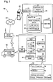
- Fig. 1 is a diagram illustrating the configuration of a route search system 10 according to a first embodiment of the invention.
- the route search system 10 includes a route server 20 provided as a route search apparatus and a car navigation system 50 mounted on an automobile 12. Both the route server 20 and the car navigation system 50 are connected to the Internet INT.
- the car navigation system 50 is wirelessly connected to the Internet INT via a base station BS.
- the route search system 10 is a system configured to display a recommended route from a set place of departure to a set destination in a visible manner on a display panel 65 included in the car navigation system 50.
- the car navigation system 50 includes a GPS receiver 69, a main controller 51, an operating part 67, a communicator 61, an audio output part 63 and a display panel 65.
- the GPS receiver 69 receives, in the form of radio wave, information for identifying the current location (latitude and longitude) of the car navigation system 50 measured by using satellites included in GPS (global positioning system).
- the display panel 65 includes a liquid crystal display and a drive circuit configured to drive the liquid crystal display.
- the display panel 65 is not necessarily limited to the liquid crystal display, but any of various display devices such as organic EL display may be employed for the display panel 65.
- the display panel 65 causes the user to visually recognize various information including a place of departure and a destination.
- a search setting window W1 displayed on the display panel 65 includes a field SL for entering the place of departure, a field DL for entering the destination and a field AI for entering additional information.
- the user operates the operating part 67 to fill the respective fields SL, DL and AI.
- the additional information herein denotes information regarding the degree of accuracy in route search to be performed by the route server 20. More specifically, this information regards a weight coefficient ⁇ for a variance value described later.
- the search setting window W1 is configured to allow for selection of one or a plurality of options among three options "quick", "standard” and "accurate”.
- the weight coefficient ⁇ is not limited to the three levels “0", “1” and “2", but may be set to a plurality of integral numbers or may be set to continuous numerical values by using a bar or the like.
- the audio output part 63 is comprised of, for example, a speaker configured to output voice and a drive circuit configured to drive the speaker.
- the communicator 61 makes wireless data communication or voice communication with the base station BS.
- the operating part 67 is an input device comprised of, for example, a numeric keypad, arrow keys and a touch panel. The operating part 67 receives inputs of various information for route search, for example, the place of departure and the destination.
- the main controller 51 controls the operations of the respective components of the car navigation system 50.
- the main controller 51 includes a CPU 52, a RAM 54 and a ROM 56.
- the CPU 52 loads and executes a program stored in the ROM 56, on the RAM 54 to implement functions for performing various processes.
- the main controller 51 controls the display panel 65 to show a map image, a recommended route and the current location.
- the main controller 51 also controls the communicator 61 to make communication with the route server 20 via the base station BS.
- the main controller 51 may measure current location information of the car navigation system 50 using the GPS via the GPS receiver 69 at predetermined time intervals to generate information indicating the place of departure.
- the route server 20 is a server configured to search a route from a place of departure to a destination specified by the car navigation system 50 in response to a route search request from the car navigation system 50 and send output information indicating a search result via the Internet INT to the car navigation system 50.
- search of a route from a place of departure to a destination performed by the route server 20 is called route search process.
- the route server 20 includes a communicator 21, a controller 22, a route database 23 (also called route DB 23) as a memory unit (memory device) and a map database 28 (also called map DB 28).
- the communicator 21 makes communication with the car navigation system 50 via the Internet INT.
- the controller 22 controls the operations of the route server 20.
- the route DB 23 stores road network data 24 that shows a road network on a map by network data.
- the road network data 24 includes link data 25 and node data 26.
- the node data 26 specifies a plurality of nodes representing reference points on roads.
- the link data 25 specifies a plurality of links connecting the plurality of nodes specified by the node data 26. The details of the link data 25 and the node data 26 will be described later.
- the map DB 43 stores map data that is to be supplied to the car navigation system 50, in a vector data format.
- the map data may be stored a raster data format such as bitmap format or JPEG format, in place of the vector format. This map data includes data regarding the configuration of features such as land features, buildings and roads.
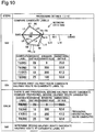
- Fig. 2 is a diagram illustrating road network data NW1 indicating roads in a predetermined area as a concrete example of the road network data 24.
- the road network data NW1 is data showing an arrangement of roads by links and nodes.
- each node in the drawings may be expressed individually by a sign including an alphabetical letter "N” with a number as the suffix
- each link in the drawings may be expressed individually by a sign including an alphabetical letter "L” with a number as the suffix.
- Fig. 2 shows four nodes N1 to N4 and four links L1 to L4.
- the nodes N1 to N4 indicate characteristic reference points on roads or lanes. This reference point may be, for example, an intersection, a road junction or a point where the width of the road starts changing.
- the links L1 to L4 indicate roads or lanes that interconnect the nodes N1 to N4.
- Route search information RSI used to search a route from a place of departure S to a destination point G is specified corresponding to each of the links L1 to L4.
- the route search information RSI includes an average cost value AC indicating an average of travel time with regard to each of the links L1 to L4 and a variance value VV indicating a variance of the travel time.
- the average cost value AC may be calculated from a histogram that is data shown by the travel time as abscissa and the probability (%) of each travel time as ordinate. According to this embodiment, this histogram is generated based on probe data collected from probe cars via a network.
- the variance value VV denotes a dispersion calculated from the histogram.
- the variance value VV may be a standard deviation in place of the dispersion.
- a first numerical value in parentheses with regard to each of the links L1 to L4 shows the average cost value AC
- a second numerical value shows the variance value VV.
- Traffic control information regarding traffic regulations is also specified in the road network data NW1.
- the traffic control information includes, for example, information indicating no left-turn from the link L3 to the link L2.
- Fig. 3 is a diagram showing the detailed structure of the link data 25 in the road network data 24.
- the link data 25 includes link attribute data 34 showing the attribute of each link.
- the attribute of a link shown by the link attribute data 34 includes a link number, a starting point node, an end point node, an average cost value AC and a variance value VV.
- the link number of the link attribute data 34 denotes a unique number assigned to each link for identification of the link.
- the starting point node of the link attribute data 34 denotes a sign for identifying a node with which the link is connected as the starting point.
- the end point node of the link attribute data 34 denotes a sign for identifying a node with which the link is connected as the end point.
- the average cost value AC of the link attribute data 34 indicates the average of the travel time of the link.
- the variance value VV of the link attribute data 34 indicates the degree of variance of the travel time of the link.
- the illustrated example of Fig. 3 shows the detailed contents of the link attribute data 34 with regard to the link L2 to which the link number "L2" is assigned. More specifically, the link attribute data 34 shows that the link L2 connects the "starting point node N2" to the "end point N3", the average cost value AC of the link L2 is 16 minutes, and the variance value VV of the link L2 is 3.
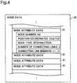
- Fig. 4 is a diagram showing the detailed structure of the node data 26 in the road network data 24.
- the node data 26 includes node attribute data 31 showing the attribute of each node.
- the attribute of a node shown by the node attribute data 31 includes a node number, position coordinates, a node type, the number of connecting links and connecting link numbers.
- the node number of the node attribute data 31 denotes a unique number assigned to each node for identification of the node.
- the position coordinates of the node attribute data 31 indicate the position of the node on the map.
- the node type of the node attribute data 31 denotes the type of a reference point shown by the node.
- the number of connecting links of the node attribute data 31 indicate the number of links connecting with the node.
- the connecting link numbers of the node attribute data 31 denote information for identifying the links connecting with the node.
- the illustrated example of Fig. 4 shows the detailed contents of the node attribute data 31 with regard to the node N2 to which the node number "N2" is assigned.
- the node attribute data 31 shows that the node N2 is located at the coordinates "Xn2 (longitude), Yn2 (latitude)), the node N2 represents an "intersection", the number of links connecting with the node N2 is "2”, and the connecting link numbers are "L1, L2".
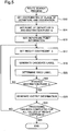
- Fig. 5 is a flowchart showing a route search process performed by a route searcher 29 of the route server 20.
- the route search process is started when the route server 20 receives startup information of the route search process from the car navigation system 50.
- the startup information includes point information regarding a place of departure and a destination set by the user using the car navigation system 50, and coefficient information regarding the weight coefficient ⁇ . More specifically, the user uses the car navigation system 50 to enter a place of departure, a destination and additional information regarding the weight coefficient ⁇ , and uses the operating part 67 to provide the route server 20 with an instruction to start the route search process.
- the information regarding the place of departure may not be generated by the user's entry but may be automatically generated based on information regarding the place of departure received by the GPS receiver 69 of the car navigation system 50.
- the route searcher 29 sets the coordinates of the place of departure and the coordinates of the destination used in the route search process, based on the point information included in the startup information (step S12).
- the route searcher 29 sets a point of departure S as the starting point of a route and a destination point G as the end point of the route in the route search process, based on the coordinates of the place of departure and the coordinates of the destination (step S14).
- the node N1 is set as the point of departure S
- the node N4 is set as the destination point G.
- a point on a link nearest to the set place of departure or the set destination (may be called lead-in point) is set as the point of departure S or the destination point G.
- the route searcher 29 subsequently determines a route having a smallest overall cost value that is a summation of the route passed through as a recommended route among routes possibly taken from the point of departure S to the destination point G.
- the overall cost value denotes the sum of an integrated value of average cost values AC corresponding to links which are passed through from the point of departure S to the destination point G and a correction value calculated based on the weight coefficient ⁇ and an integrated value of variance values VV corresponding to the links which are passed through.
- the route searcher 29 sets departure point information regarding the point of departure S (step S16).
- the departure point information indicates an average cost value AC and a variance value VV from the point of departure S to a next node.
- both the average cost value AC and the variance value VV are set to zero.
- the average cost value AC and the variance value VV corresponding to the link on which the point of departure S is located are calculated and set by division using a ratio of a distance from the point of departure S to an end point of the link to a distance from a starting point to the end point of the link. According to this embodiment, both the average cost value AC and the variance value VV at the point of departure S are set to zero.
- the route searcher 29 sets the weight coefficient ⁇ (step S17).
- the weight coefficient ⁇ is set, based on the coefficient information with regard to the weight coefficient ⁇ included in the startup information supplied from the car navigation system 50.
- the route searcher 29 selects an arbitrary value of the weight coefficient ⁇ and performs subsequent steps.
- the route searcher 29 generates a candidate label that is an index for determining links which are to be passed through on a route from the point of departure S to the destination point G (step S18).
- the candidate label When the candidate label is generated for a certain link located in the middle of the route from the point of departure S to the destination point G, the candidate label is set at an end point (node) of the certain link.
- the candidate label is comprised of an integrated value of the average cost values AC of the respective links between the point of departure S and the certain link and an integrated value of the variance values VV of the respective links between the point of departure S and the certain link.
- a candidate overall cost value is then calculated, based on the information included in the candidate label. More specifically, the candidate overall cost value is calculated according to Equation (2) given below: [Math.
- the route searcher 29 determines a candidate label having a smallest candidate overall cost value among at least one candidate overall cost value, as a fixed label (step S20). Determining the fixed label fixes a route (halfway route) to a node (temporary fixed node) that is located in the middle of the route from the point of departure S to the destination point G. The route searcher 29 subsequently determines whether a last link or a node (last node) that is an end point of the last link in the halfway route toward the destination point G is a link or a node where the destination point G is located (step S22).
- the route searcher 29 fixes the halfway route as a recommended route.
- the route searcher 29 then generates output information to display the fixed recommended route on the display panel 65 of the car navigation system 50 (step S23). More specifically, the output information includes information regarding the recommended route from the point of departure S to the destination point G, information regarding an average travel time from the point of departure S to the destination point G and variance information regarding a variance of the average travel time. The details of this output information will be described later.
- the route searcher 29 determines whether the recommended route has been fixed with regard to all the values of the weight coefficient ⁇ included in the startup information (step S24). When it is determined that the recommended route has been fixed with regard to all the values of the weight coefficient ⁇ , the route searcher 29 terminates the route search process.
- the route searcher 29 When it is determined that the last link or the last node is not the link or the node where the destination point G is located, the route searcher 29 further extends the search tree from the end point of the halfway route toward the destination point G by the Dijkstra's algorithm and generates a candidate label (step S18). The route searcher 29 then performs the series of processes of and after step S20 again. When it is determined that the recommended route has not yet been fixed with regard to all the values of the weight coefficient ⁇ , the route searcher 29 sets another value of the weight coefficient ⁇ for which the recommended route has not yet been fixed at step S17 and performs the subsequent series of processes again.
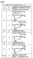
- Fig. 6 is a diagram showing a concrete example of the route search process. Steps shown in Fig. 6 correspond to the steps shown in Fig. 5 . Sub-steps shown in Fig. 6 show concrete processes performed at the respective steps shown in Fig. 5 . Fig. 6 illustrates a concrete example of the route search process when the route searcher 29 sets the node N1 shown in Fig. 2 as the point of departure S and sets the node N4 shown in Fig. 2 as the destination point G. The weight coefficient ⁇ is set to "1" at step S17. Sub-steps C1 and C2 respectively correspond to steps S14 and S16.
- the route searcher 29 extends the search tree from the point of departure S toward the destination point G by the Dijkstra's algorithm. More specifically, the route searcher 29 (shown in Fig. 1 ) refers to the node data 26 and the link data 25 and sets a candidate label from the point of departure S to an end point of a next link as shown in Fig. 6 (step S18).
- first links from the node N1 as the point of departure S toward the destination point are the links L1 and the links L3.
- the route searcher 29 sets a candidate label T1 for a route from the point of departure S to an end point of the link L1 (or more specifically, at the end point of the link L1).
- the route searcher 29 then calculates a candidate overall cost value V1 based on the candidate label T1.
- the route searcher 29 also sets a candidate label T2 for a route from the point of departure S to an end point of the link L3 (sub step C4).
- the route searcher 29 then calculates a candidate overall cost value V2 based on the candidate label T2.
- a candidate overall cost value of the route from the point of departure S to a next node N2 is calculated according to Equation (2) given above. More specifically, an integrated value of average cost values AC (integrated cost value) "15” is calculated by summing up an average cost value AC "0" set at the point of departure S and an average cost value AC "15” set at the link L1. At sub-step C3, an integrated value of variance values VV (integrated variance value) "3” is also calculated by summing up a variance value VV "0" set at the point of departure S and a variance value VV "3" set at the link L1.
- the route searcher 29 subsequently adds a correction value that is the product of the positive square root of the integrated variance value "3" and the weight coefficient ⁇ to the integrated cost value "15”, so as to calculate a candidate overall cost value V1.
- the calculated candidate overall cost value V1 is equal to "16.4".
- the candidate overall cost value is rounded off to one decimal place.
- a candidate overall cost value of the route from the point of departure S to a next node N3 is calculated according to Equation (2) given above. More specifically, an integrated cost value "30" is calculated by summing up the average cost value AC "0" set at the point of departure S and an average cost value AC "30” set at the link L3. At sub-step C4, an integrated variance value VV “15” is also calculated by summing up the variance value VV "0" set at the point of departure S and a variance value "15” set at the link L3.
- the route searcher 29 subsequently adds a correction value that is the product of the positive square root of the integrated variance value "15" and the weight coefficient ⁇ to the integrated cost value "30", so as to calculate a candidate overall cost value V2.
- the calculated candidate overall cost value V2 is equal to "37.7".
- a candidate label having the smaller candidate overall cost value between the candidate overall cost values V1 and V2 is determined as a fixed label.
- the candidate label having the candidate overall cost value V1 is determined as a fixed label. Accordingly the route from the point of departure S to the link L1 is fixed as a halfway route.
- the route searcher 29 further extends the search tree by the Dijkstra's algorithm to generate a candidate label (at sub-step C6).
- the route searcher 29 refers to the node data 26 and the link data 25 to specify the link L2 from the node N2 toward the destination point G, and generates a candidate label T3 for a route from the point of departure S through the link L1 and the node N2 to the link L2.
- a candidate overall cost value V3 of the candidate label T3 is then calculated according to Equation (2) given above, like sub-steps C3 and C4.
- the candidate overall cost value V3 of the candidate label T3 generated at sub-step C6 is equal to "35.9".
- the candidate label T3 having the candidate overall cost value V3 is set at an end point of the link L2 (node N3).
- the route searcher 29 compares the candidate overall cost values V2 and V3 of the two candidate labels T2 and T3 and determines the candidate label T3 having the smaller candidate overall cost value V3 as a fixed label, while deleting the other candidate label T2. Accordingly the route from the point of departure S through the link L1, the node N2 and the link L2 to the node N3 is fixed as a halfway route.
- the route searcher 29 When it is subsequently determined that the link L2 or the end point of the link L2 (node N3) is not the link or the node where the destination point G is located, the route searcher 29 further extends the search tree by the Dijkstra's algorithm to generate a candidate label T4 (at sub-step C8). More specifically, the route searcher 29 refers to the node data 26 and the link data 25 to specify the link L4 from the node N3 toward the destination point G, and generates a candidate label T4 for a route from the point of departure S through the link L1, the node N2, the link L2 and the node N3 to the link L4.
- the route searcher 29 determines the candidate label T4 as a fixed label. Accordingly the route from the point of departure S to the link L4 having the candidate label T4 determined as the fixed label is fixed as a halfway route. Since the destination point G is the node N4, the destination point G is located at the link L4 or the end point of the link L4 (node N4) in the fixed halfway route. The route searcher 29 accordingly determines the halfway route fixed at sub-step C8 as a recommended route from the point of departure S to the destination point G (at sub-step C9).
- the route searcher 29 also refers to the link data 25 to integrate the average cost values AC corresponding to the links L1, L2 and L4 of the recommended route and thereby calculates an average travel time of the recommended route.
- the average travel time is "46 minutes”.
- the route searcher 29 also refers to the link data to calculate an integrated value of variance values (integrated variance value) corresponding to the links L1, L2 and L4 of the recommended route.
- the positive square root of the integrated variance value is provided as a variance index (standard deviation) indicating the degree of variance of the average travel time. According to this embodiment, the variance index is "4".
- Fig. 7 is a diagram illustrating an output information window W2 displayed on the display panel 65.
- the output information window W2 includes recommended routes and values of a travel time determined for respective values of the weight coefficient ⁇ .
- the recommended route is shown by providing marks such as red lines on map data.
- the first embodiment determines the recommended route from the point of departure S representing the place of departure to the destination point G representing the destination, based on the average cost value AC, the variance value VV and the weight coefficient ⁇ .
- This configuration allows for flexible route search by simply changing the value of the weight coefficient ⁇ .
- Fig. 8 is a flowchart showing a route search process according to a second embodiment of the invention.
- the route search process of the second embodiment differs from the route search process of the first embodiment (shown in Fig. 5 ) by the details of the process of determining a candidate label as a fixed label.
- Fig. 8 accordingly shows the details of a process of determining a fixed label (step S20a) in the route search process.
- the other processes and the configuration of the route search system 10 are similar to those of the first embodiment and are not specifically described here.
- a label having the smallest value among the candidate overall cost values is determined as a fixed label.
- a fixed label is determined based on the set weight coefficient ⁇ when a predetermined condition is satisfied as described below in detail.
- the route searcher 29 first compares the candidate overall cost values of the generated candidate labels (step S40). When there are a plurality of candidate overall cost values, the route searcher 29 determines whether a difference between the candidate overall cost values is equal to or less than a predetermined value (step S42). According to this embodiment, the route searcher 29 extracts two candidate overall cost values or more specifically the smallest and the second smallest candidate overall cost values among the plurality of candidate overall cost values, and calculates a difference between the two extracted candidate overall cost values. According to this embodiment, the predetermined value is set to "0.2". The predetermined value may, however, be equal to "0" or may be equal to a numerical value other than 0.2.
- a candidate label having the smallest candidate overall cost value is determined as a fixed label (step S44).
- a fixed label is determined, based on the weight coefficient ⁇ (step S46). More specifically, in a first case having the small weight coefficient ⁇ , a candidate label having the minimum integrated cost value (first term on the right side of Equation (2)) among the plurality of candidate labels is determined as a fixed label.
- a candidate label having the minimum integrated variance value (second term on the right side of Equation (2)) is determined as a fixed label.
- the case having the weight coefficient ⁇ equal to "0" or "1" corresponds to the first case
- the case having the weight coefficient ⁇ equal to "2" corresponds to the second case.
- the second embodiment flexibly determines the recommended route from the point of departure S to the destination point G, based on the set weight coefficient ⁇ . For example, in the first case having the small weight coefficient ⁇ , more emphasis is placed on the average cost value AC than the variance value VV, and the route having the smallest integrated value of the average cost values AC is determined as the recommended route. In the second case having the larger weight coefficient ⁇ than that in the first case, more emphasis is placed on the variance value VV than the average cost value AC, and the route having the smallest integrated value of the variance values is determined as the recommended route.
- Fig. 9 is a flowchart showing a route search process according to a third embodiment of the invention.
- Fig. 10 is a first diagram illustrating the flowchart of Fig. 9 .
- Fig. 11 is a second diagram illustrating the flowchart of Fig. 9 .
- Fig. 12 is a third diagram illustrating the flowchart of Fig. 9 .
- Figs. 10 and 12 illustrate road network data NW2 used for the purpose of describing the third embodiment.
- NW2 used for the purpose of describing the third embodiment.
- a node N6 is set as the point of departure S
- a node N30 is set as the destination point G
- nodes N6 to N11 which are interconnected by the links L5 to L14 are also illustrated.
- the route search process of the third embodiment differs from the route search process of the first embodiment (shown in Fig. 5 ) by the details of the process of determining a candidate label as a fixed label and a process of determining a recommended route when reaching the destination point G.
- Fig. 9 accordingly shows the details of a process of determining a fixed label (step S20b) in the route search process.
- the processes similar to those of the first embodiment are not specifically described here.
- the configuration of the route search system 10 (shown in Fig. 1 ) is similar to that of the first embodiment.
- a second candidate label that satisfies a predetermined condition is determined as a fixed label.
- the weight coefficient ⁇ is set to "2".
- candidate labels T5 to T8 respectively corresponding to routes R5 to R8 from the point of departure S to a node N10 are set at the node N10, in order to determine a halfway route from the point of departure S to the node N10.
- An integrated value of average cost values AC (integrated cost value), an integrated value of variance values VV. (integrated variance value), and a candidate overall cost value calculated according to Equation (2) given above with regard to each of the candidate labels T5 to T8 are also shown in the field of the processing details of step S52 in Fig. 10 .
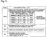
- the route searcher 29 first compares the candidate overall cost values of the generated candidate labels T5 to T8 (shown in Fig. 10 ) (step S52), and subsequently determines a candidate label having the smallest candidate overall cost value among the plurality of candidate overall cost values, as a first candidate label (step S54).
- the candidate label T5 having the candidate overall cost value of "35.0" is determined as the first candidate label, so that the route R5 corresponding to the candidate label T5 is determined as a first halfway route candidate R5 (step S54).
- the route searcher 29 subsequently determines whether there is any provisional second halfway route candidate (step S56).
- the provisional second halfway route candidate denotes a route candidate having a smaller integrated cost value than the integrated cost value of the first halfway route candidate R5 among the halfway route candidates R6 to R8 other than the first halfway route candidate R5 (remaining halfway route candidates R6 to R8) as shown in Fig. 10 .
- all the integrated cost values "18, 19, 25" of the candidate labels T6 to T8 are smaller than the integrated cost value "29" of the candidate label T5, so that the halfway route candidates R6 to R8 corresponding to the candidate labels T6 to T8 are the provisional second halfway route candidates R6 to R8.
- the route searcher 29 compares the candidate labels T6 to T8 corresponding to the provisional second halfway route candidates R6 to R8 (step S58) and determines a candidate label having the smallest candidate overall cost value as a second candidate label (step S60).
- the candidate label T7 having the candidate overall cost value of "47.3" is determined as the second candidate label, so that the route R7 corresponding to the candidate label T7 is determined as a second halfway route candidate R7 (step S60).
- the route searcher 29 subsequently specifies the halfway route candidates R6 and R8 other than the previously determined first and second halfway route candidates R5 and R7 as remaining halfway route candidates R6 and R8 and performs the processing of step S56.
- the route searcher 29 specifies the second halfway route candidate R7 determined immediately before the processing of step S56 as the first halfway route candidate R7 and determine whether there is any route candidate having a smaller integrated cost value than the integrated cost value "19" of the first halfway route candidate R7.
- the integrated cost value "18" of the candidate label T6 is smaller than the integrated cost value "19" of the candidate label T7, so that the halfway route candidate R6 corresponding to the candidate label T6 is the provisional second halfway route candidate R6.
- the route searcher 29 then performs the processing of steps S58 and S60 shown in Fig. 9 .
- steps S58 and S60 shown in Fig. 9 .
- the route searcher 29 specifies the halfway route candidate R8 other than the previously determined first and second halfway route candidates R5 to R7 as a remaining halfway route candidate R8 and performs the processing of step S56 again.
- the integrated cost value "25" of the candidate label T8 corresponding to the remaining halfway route candidate R8 is larger than the integrated cost value "18" of the candidate label T6 corresponding to the most recently determined second halfway route candidate R6.
- the route searcher 29 then provides a negative answer "NO" at step S56 and determines the previously determined candidate labels T5 to T7 as fixed labels. Accordingly the first and second halfway route candidates R5 to R7 corresponding to the fixed labels T5 to T7 are determined as halfway routes R5 to R7 (step S62).
- the route searcher 29 extends the search tree from the halfway routes R5 to R7 corresponding to the fixed labels T5 to T7 toward the destination point G and generates candidate labels T9 to T11.
- the route searcher 29 performs the processing of steps S52 to S62 with regard to the candidate labels T9 to T11.
- the processing of steps S52 and S54 is performed to select the candidate label T11 having the smallest candidate overall cost value and determine the route R11 corresponding to the candidate label T11 as a first halfway route candidate R11.
- the processing of step S56 is subsequently performed.
- Fig. 12 the route searcher 29 extends the search tree from the halfway routes R5 to R7 corresponding to the fixed labels T5 to T7 toward the destination point G and generates candidate labels T9 to T11.
- the route searcher 29 performs the processing of steps S52 to S62 with regard to the candidate labels T9 to T11.
- the processing of steps S52 and S54 is performed to select the candidate label T11 having the smallest candidate overall cost value and determine the route R11 corresponding
- route candidate R10 provisional second halfway route candidate R10 having a smaller integrated cost value than the integrated cost value "79" of the first halfway route candidate R11 out of remaining halfway route candidates R9 and R10, so that an affirmative answer "YES" is provided at step S56.
- the processing of steps S58 and S60 is then performed.
- the route searcher 29 specifies the halfway route candidate R9 other than the previously determined first and second halfway route candidates R11 and R10 as a remaining halfway route candidate R9 and performs the processing of step S56 again.
- the integrated cost value "89" of the candidate label T9 corresponding to the remaining halfway route candidate R9 is larger than the integrated cost value "78" of the candidate label T10 corresponding to the most recently determined second halfway route candidate R10.
- the route searcher 29 then provides a negative answer "NO" at step S56 and determines the previously determined candidate labels T11 and T10 as fixed labels. Accordingly the first and second halfway route candidates R11 and R10 corresponding to the fixed labels T11 and T10 are determined as halfway routes R11 and R10 (step S62).
- the route searcher 29 determines whether a last link or a node (last node) that is an end point of the last link in the halfway route toward the destination point G is a link or a node where the destination point G is located (step S22 in Fig. 5 ). When it is determined that the last link or the last node is the link or the node where the destination point G is located, the route searcher 29 fixes the halfway route as a recommended route. When there are a plurality of halfway routes (for example, the halfway routes RIO and R11 at step S62 in Fig. 12 ), the route searcher 29 fixes a halfway route having the smallest candidate overall cost value among the plurality of halfway routes, as a recommended route.
- the halfway route R10 having the smaller candidate overall cost value out of the halfway route R10 and R11 determined at step S62 is fixed as a recommended route.
- the candidate label T5 is the first candidate label having the smallest candidate overall cost value as shown in Fig. 10 .
- the candidate label T11 is the first candidate label as shown in Fig. 12 .
- the candidate label T11 is a label by extending the search tree from the candidate label T7 in Fig. 10 . In the case of extending the search tree with determining only a label having the smallest candidate overall cost value as a fixed label, a route having the smallest candidate overall cost value is likely to be not determinable as a recommended route.
- this embodiment determines a candidate label having the smallest candidate overall cost value (first candidate label) and additionally a candidate label that satisfies a predetermined condition (second candidate label) among candidate labels having smaller integrated cost values than the first candidate label, as fixed labels.
- first candidate label a candidate label having the smallest candidate overall cost value
- second candidate label a candidate label that satisfies a predetermined condition
- the positive square root of the integrated variance value is calculated as the variance index.
- statistical information indicating histograms used for calculating the average cost values AC of the respective links constituting a recommended route or a halfway route may be used. More specifically, statistical information of the respective links may be processed by convolution operation, and a standard deviation calculated from statistical information indicating a histogram after the convolution operation may be used as the variance index. An average cost value calculated from the statistical information indicating the histogram after the convolution operation may be used to determine a recommended route or a halfway route. The details are described below.
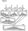
- Fig. 13 is a conceptual view showing the convolution operation. In the illustrated example of Fig.
- a recommended route from a point of departure S to a destination point G is comprised of links L10, L12 and L14.
- the link data 25 includes data (statistical information) indicating histograms H10, H12 and H14, in addition to link numbers, starting point nodes, end point nodes, average cost values AC and variance values VV.
- the histograms H10, H12 and H14 may be generated, for example, based on probe data collected from probe cars. In the histograms H10, H12 and H14, the travel time (minutes) of a link is shown as abscissa and the probability (%) of each travel time is shown as ordinate.
- the histograms of the first link L10 and the next link L12 in a route from the point of departure S toward the destination point G are processed by convolution operation, and a new histogram H18 is generated.
- the histogram H14 of the next link L14 subsequent to the link L12 and the histogram H18 are processed by convolution operation, and a new histogram H20 is generated.
- a standard deviation is calculated from statistical information indicating the histograms H18 and H20 generated by the convolution operation.
- the convolution operation of the histograms is defined by Equation (3) given below: [Math.
- F(m) on the left side denotes a function generated by convolution operation of two histograms
- f denotes a function defined by the first histogram
- g denotes a function defined by the second histogram
- n denotes the travel time in the first histogram
- m denotes the travel time (total time) in convolution operation of the first histogram and the second histogram.
- this also calculates the standard deviation as the variance index of the travel time in the recommended route or the halfway route. Calculating the standard deviation from the statistical information indicating a histogram after the convolution operation provides a more accurate variance index having a reduced error, compared with the above embodiments.
- the route searcher 29 processes statistical information indicating respective histograms of the travel time of respective links that are passed through in halfway route candidates as candidates of a halfway route by convolution operation, so as to generate candidate statistical information indicating histograms of the travel time in the respective halfway route candidates.
- the route searcher 29 subsequently calculates a candidate overall cost value of each halfway route candidate according to a function including the weight coefficient ⁇ and a candidate average cost value At1 indicating an average of the travel time of the halfway route candidate and a candidate variance value VV (dispersion in this modification) indicating the degree of variance of the halfway route candidate that are calculated from the candidate statistical information.
- Equation (4) The right side of Equation (4) given above is defined by a first term representing the candidate average cost value and a second term representing a correction value as the product of the positive square root of the candidate variance value VV and the weight coefficient ⁇ , but this is not restrictive.
- the second term may be the product of the candidate variance value VV and the weight coefficient ⁇ .
- the right side of Equation (4) given above may additionally include a third term and a fourth term.
- the third term may be defined as a term for increasing the cost value as traffic congestion information in the case of traffic congestion on a specific link.
- This process uses the candidate variance value VV calculated from the candidate statistical information after the convolution operation to calculate the candidate overall cost value. This enables the halfway route to be determined using the candidate overall cost value calculated from the more accurate variance value VV having a reduced error.
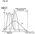
- Fig. 14 is a diagram showing a method of calculating an average cost value AC and a variance value VV with regard to a specific link L.
- a graph 14A in Fig. 14 is generated based on probe data and has the travel time (minutes) of the link L as abscissa and the number of samples n (probability) of each travel time as ordinate. The probability is calculated based on the number of samples.
- a graph 14B is a conceptual diagram of a normal distribution based on the average value of the information expressed by the graph 14A (original information) and the variance value determined from information after deletion of data of the travel time estimated to be affected by a feature from the graph 14A.
- a graph 14C is a conceptual diagram of a normal distribution based on the information expressed by the graph 14A (original information).
- the link L (specific link L) has a specific feature such as a traffic light or a railway crossing that affects the travel time or when a link adjacent to the specific link L has a specific feature such as a traffic light or a railway crossing
- the specific feature provides an effect of increasing the travel time in the specific link L at a certain frequency. It is, however, unlikely that the travel time is increased by the specific feature in all the links that are passed through from a place of departure to a destination.
- the average cost value AC and the variance value VV of the specific link L may thus be calculated as described below.
- the average cost value AC may be calculated from the entire travel time data expressed by the graph 14A as the original information and their probabilities.
- the variance value VV may be calculated from the travel time data estimated to be not affected by the specific feature and their probabilities out of the entire data expressed by the graph 14A as the original information.
- the variance value VV may be calculated based on the variance value determined from data after deletion of data, such as the travel time, estimated to be affected by the specific feature from the data of the original information.
- the "data estimated to be affected by the specific feature” may be data of the longer travel time than a minimum travel time at which the number of samples becomes equal to or lower than a predetermined rate (for example, equal to or lower than 10%) of the number of samples na corresponding to the average cost value AC, out of the data of the longer travel time than the average cost value AC.
- the "data estimated to be affected by the specific feature" may be data of the long travel time at a predetermined rate or higher among the number of samples n (for example, data of the top 10%).
- data that is equal to or less than the number of samples nb out of the data having the longer travel time than the average cost value AC is estimated as data affected by the feature and is omitted from calculation of the variance value VV.
- the normal distribution based on all the data of the original information (graph 14C) provides the excessive variance value VV.
- the normal distribution based on the information after deletion of the data estimated to be affected by the feature (graph 14B) is, on the other hand, appropriately corrected without providing the excessive variance value VV.
- the second modification provides the average cost value AC that accurately reflects the travel time data of the original information, while correcting the variance value that is made excessive by the effect of the feature.
- the route server 20 performs the route search process, and the car navigation system 50 receives the result of the route search process and displays the output information on the display panel 65.
- This configuration is, however, not restrictive, but the output information may be displayed on the display panel 65 by any of various other configurations.
- the route server 20 may send network data of a required range including a place of departure and a destination to the car navigation system 50.
- the car navigation system 50 may receive the network data, perform the route search process and display the output information on the display panel 65.
- the car navigation system 50 may provide the user with audio output information.
- the car navigation system 50 itself may be provided with the functions of the route server 20.
- the car navigation system 50 in the first and the second embodiments described above may be replaced by any of various other devices having the function of providing the user with output information, for example, a cell phone or a personal computer.
- the overall cost value and the candidate overcall cost value are calculated according to the relational expressions of Equations (1) and (2) given above.
- the second term on the right side is the product of the weight coefficient ⁇ and a value having the positive correlation to the integrated value of the variance value VV (more specifically, the positive square root).
- the overall cost value and the candidate overall cost value may be calculated using a function including the average cost value AC, the variance value VV and the weight coefficient ⁇ .
- the second term on the right side in Equation (1) given above may be replaced by the product of the integrated value of the variance value and the weight coefficient.
- the right side of Equation (1) or (2) given above may additionally include a third term and a fourth term.
- the third term may be defined as a term for increasing the cost value as traffic congestion information in the case of traffic congestion on a specific link.
- Part of the functions implemented by the software configuration in the above first or second embodiment may be implemented by a hardware configuration, and part of the functions implemented by the hardware configuration may be implemented by a software configuration.
Description
- The present application claims priority from Japanese patent application
P2014-36275 filed on February 27, 2014 - The present invention relates to a technique of searching a route from a place of departure to a destination.
- Car navigation system mounted on the automobile, cell phones, handheld game consoles, PNDs (Personal Navigation Devices) and PDAs (Personal Digital Assistants) have recently been known as the route search apparatus configured to search a route from a place of departure to a destination as described in, for example,
JP 2012-141145A JP 2008-241605A - For example, the technique disclosed in
JP 2012-141145A - In the technique disclosed in
JP 2012-141145A -
EP 1 614 996 A1claim 1. - This problem is solved by the features of appended
apparatus claim 1 and the corresponding method and program claim. Advantageous embodiments are subject of the dependent claims. -
-
Fig. 1 is a diagram illustrating the configuration of a route search system; -
Fig. 2 is a diagram illustrating network data; -
Fig. 3 is a diagram showing the detailed structure of link data; -
Fig. 4 is a diagram showing the detailed structure of node data; -
Fig. 5 is a flowchart showing a route search process; -
Fig. 6 is a diagram showing a concrete example of the route search process; -
Fig. 7 is a diagram showing an output information window displayed on a display panel; -
Fig. 8 is a flowchart showing a route search process according to a second embodiment; -
Fig. 9 is a flowchart showing a route search process according to a third embodiment of the invention; -
Fig. 10 is a first diagram illustrating the flowchart ofFig. 9 ; -
Fig. 11 is a second diagram illustrating the flowchart ofFig. 9 ; -
Fig. 12 is a third diagram illustrating the flowchart ofFig. 9 ; -
Fig. 13 is a conceptual view showing a convolution operation; and -
Fig. 14 is a diagram illustrating a method of calculating an average cost value and a variance value. -
Fig. 1 is a diagram illustrating the configuration of aroute search system 10 according to a first embodiment of the invention. Theroute search system 10 includes aroute server 20 provided as a route search apparatus and acar navigation system 50 mounted on anautomobile 12. Both theroute server 20 and thecar navigation system 50 are connected to the Internet INT. Thecar navigation system 50 is wirelessly connected to the Internet INT via a base station BS. Theroute search system 10 is a system configured to display a recommended route from a set place of departure to a set destination in a visible manner on adisplay panel 65 included in thecar navigation system 50. - The
car navigation system 50 includes aGPS receiver 69, amain controller 51, anoperating part 67, acommunicator 61, anaudio output part 63 and adisplay panel 65. TheGPS receiver 69 receives, in the form of radio wave, information for identifying the current location (latitude and longitude) of thecar navigation system 50 measured by using satellites included in GPS (global positioning system). - The
display panel 65 includes a liquid crystal display and a drive circuit configured to drive the liquid crystal display. Thedisplay panel 65 is not necessarily limited to the liquid crystal display, but any of various display devices such as organic EL display may be employed for thedisplay panel 65. Thedisplay panel 65 causes the user to visually recognize various information including a place of departure and a destination. A search setting window W1 displayed on thedisplay panel 65 includes a field SL for entering the place of departure, a field DL for entering the destination and a field AI for entering additional information. The user operates theoperating part 67 to fill the respective fields SL, DL and AI. The additional information herein denotes information regarding the degree of accuracy in route search to be performed by theroute server 20. More specifically, this information regards a weight coefficient λ for a variance value described later. The search setting window W1 is configured to allow for selection of one or a plurality of options among three options "quick", "standard" and "accurate". - The following relationships may be provided between the three options shown in the field AI of additional information and the weight coefficient λ:
- (i) option "quick": The weight coefficient λ is set to "0", and a shortest route having the shortest average travel time among a plurality of routes from the place of departure to the destination is determined irrespective of the variance value as a recommended route by the
route server 20; - (ii) option "standard": The weight coefficient λ is set to "1", and a route placing more emphasis on the variance value than the option "quick" among the plurality of routes from the place of departure to the destination is determined as a recommended route by the
route server 20; and - (iii) option "accurate": The weight coefficient λ is set to "2", and a route placing more emphasis on the variance value than the option "standard" among the plurality of routes from the place of departure to the destination is determined as a recommended route by the
route server 20. - The weight coefficient λ is not limited to the three levels "0", "1" and "2", but may be set to a plurality of integral numbers or may be set to continuous numerical values by using a bar or the like.
- The
audio output part 63 is comprised of, for example, a speaker configured to output voice and a drive circuit configured to drive the speaker. Thecommunicator 61 makes wireless data communication or voice communication with the base station BS. Theoperating part 67 is an input device comprised of, for example, a numeric keypad, arrow keys and a touch panel. Theoperating part 67 receives inputs of various information for route search, for example, the place of departure and the destination. - The
main controller 51 controls the operations of the respective components of thecar navigation system 50. Themain controller 51 includes aCPU 52, aRAM 54 and aROM 56. TheCPU 52 loads and executes a program stored in theROM 56, on theRAM 54 to implement functions for performing various processes. For example, themain controller 51 controls thedisplay panel 65 to show a map image, a recommended route and the current location. Themain controller 51 also controls thecommunicator 61 to make communication with theroute server 20 via the base station BS. Themain controller 51 may measure current location information of thecar navigation system 50 using the GPS via theGPS receiver 69 at predetermined time intervals to generate information indicating the place of departure. - The
route server 20 is a server configured to search a route from a place of departure to a destination specified by thecar navigation system 50 in response to a route search request from thecar navigation system 50 and send output information indicating a search result via the Internet INT to thecar navigation system 50. In the description below, search of a route from a place of departure to a destination performed by theroute server 20 is called route search process. Theroute server 20 includes acommunicator 21, acontroller 22, a route database 23 (also called route DB 23) as a memory unit (memory device) and a map database 28 (also called map DB 28). Thecommunicator 21 makes communication with thecar navigation system 50 via the Internet INT. Thecontroller 22 controls the operations of theroute server 20. Theroute DB 23 storesroad network data 24 that shows a road network on a map by network data. Theroad network data 24 includeslink data 25 andnode data 26. Thenode data 26 specifies a plurality of nodes representing reference points on roads. Thelink data 25 specifies a plurality of links connecting the plurality of nodes specified by thenode data 26. The details of thelink data 25 and thenode data 26 will be described later. The map DB 43 stores map data that is to be supplied to thecar navigation system 50, in a vector data format. The map data may be stored a raster data format such as bitmap format or JPEG format, in place of the vector format. This map data includes data regarding the configuration of features such as land features, buildings and roads. -
Fig. 2 is a diagram illustrating road network data NW1 indicating roads in a predetermined area as a concrete example of theroad network data 24. The road network data NW1 is data showing an arrangement of roads by links and nodes. In the description below, each node in the drawings may be expressed individually by a sign including an alphabetical letter "N" with a number as the suffix, and each link in the drawings may be expressed individually by a sign including an alphabetical letter "L" with a number as the suffix.Fig. 2 shows four nodes N1 to N4 and four links L1 to L4. The nodes N1 to N4 indicate characteristic reference points on roads or lanes. This reference point may be, for example, an intersection, a road junction or a point where the width of the road starts changing. The links L1 to L4 indicate roads or lanes that interconnect the nodes N1 to N4. Route search information RSI used to search a route from a place of departure S to a destination point G is specified corresponding to each of the links L1 to L4. The route search information RSI includes an average cost value AC indicating an average of travel time with regard to each of the links L1 to L4 and a variance value VV indicating a variance of the travel time. The average cost value AC may be calculated from a histogram that is data shown by the travel time as abscissa and the probability (%) of each travel time as ordinate. According to this embodiment, this histogram is generated based on probe data collected from probe cars via a network. According to this embodiment, the variance value VV denotes a dispersion calculated from the histogram. According to another embodiment, the variance value VV may be a standard deviation in place of the dispersion. In the road network data NW1 ofFig. 2 , a first numerical value in parentheses with regard to each of the links L1 to L4 shows the average cost value AC, and a second numerical value shows the variance value VV. Traffic control information regarding traffic regulations is also specified in the road network data NW1. The traffic control information includes, for example, information indicating no left-turn from the link L3 to the link L2. -
Fig. 3 is a diagram showing the detailed structure of thelink data 25 in theroad network data 24. Thelink data 25 includeslink attribute data 34 showing the attribute of each link. The attribute of a link shown by thelink attribute data 34 includes a link number, a starting point node, an end point node, an average cost value AC and a variance value VV. - The link number of the
link attribute data 34 denotes a unique number assigned to each link for identification of the link. The starting point node of thelink attribute data 34 denotes a sign for identifying a node with which the link is connected as the starting point. The end point node of thelink attribute data 34 denotes a sign for identifying a node with which the link is connected as the end point. The average cost value AC of thelink attribute data 34 indicates the average of the travel time of the link. The variance value VV of thelink attribute data 34 indicates the degree of variance of the travel time of the link. The illustrated example ofFig. 3 shows the detailed contents of thelink attribute data 34 with regard to the link L2 to which the link number "L2" is assigned. More specifically, thelink attribute data 34 shows that the link L2 connects the "starting point node N2" to the "end point N3", the average cost value AC of the link L2 is 16 minutes, and the variance value VV of the link L2 is 3. -
Fig. 4 is a diagram showing the detailed structure of thenode data 26 in theroad network data 24. Thenode data 26 includesnode attribute data 31 showing the attribute of each node. The attribute of a node shown by thenode attribute data 31 includes a node number, position coordinates, a node type, the number of connecting links and connecting link numbers. - The node number of the
node attribute data 31 denotes a unique number assigned to each node for identification of the node. The position coordinates of thenode attribute data 31 indicate the position of the node on the map. The node type of thenode attribute data 31 denotes the type of a reference point shown by the node. The number of connecting links of thenode attribute data 31 indicate the number of links connecting with the node. The connecting link numbers of thenode attribute data 31 denote information for identifying the links connecting with the node. The illustrated example ofFig. 4 shows the detailed contents of thenode attribute data 31 with regard to the node N2 to which the node number "N2" is assigned. More specifically, thenode attribute data 31 shows that the node N2 is located at the coordinates "Xn2 (longitude), Yn2 (latitude)), the node N2 represents an "intersection", the number of links connecting with the node N2 is "2", and the connecting link numbers are "L1, L2". -
Fig. 5 is a flowchart showing a route search process performed by aroute searcher 29 of theroute server 20. The route search process is started when theroute server 20 receives startup information of the route search process from thecar navigation system 50. The startup information includes point information regarding a place of departure and a destination set by the user using thecar navigation system 50, and coefficient information regarding the weight coefficient λ. More specifically, the user uses thecar navigation system 50 to enter a place of departure, a destination and additional information regarding the weight coefficient λ, and uses the operatingpart 67 to provide theroute server 20 with an instruction to start the route search process. The information regarding the place of departure may not be generated by the user's entry but may be automatically generated based on information regarding the place of departure received by theGPS receiver 69 of thecar navigation system 50. - On the start of the route search process, the
route searcher 29 sets the coordinates of the place of departure and the coordinates of the destination used in the route search process, based on the point information included in the startup information (step S12). After step S12, theroute searcher 29 sets a point of departure S as the starting point of a route and a destination point G as the end point of the route in the route search process, based on the coordinates of the place of departure and the coordinates of the destination (step S14). In an example described in this embodiment, the node N1 is set as the point of departure S, and the node N4 is set as the destination point G. When the set place of departure or the set destination is not located at a node, a point on a link nearest to the set place of departure or the set destination (may be called lead-in point) is set as the point of departure S or the destination point G. Theroute searcher 29 subsequently determines a route having a smallest overall cost value that is a summation of the route passed through as a recommended route among routes possibly taken from the point of departure S to the destination point G. The overall cost value denotes the sum of an integrated value of average cost values AC corresponding to links which are passed through from the point of departure S to the destination point G and a correction value calculated based on the weight coefficient λ and an integrated value of variance values VV corresponding to the links which are passed through. More specifically, according to this embodiment, the overall cost value is determined by Equation (1) given below:
[Math. 1]
- After step S14, the
route searcher 29 sets departure point information regarding the point of departure S (step S16). The departure point information indicates an average cost value AC and a variance value VV from the point of departure S to a next node. When the point of departure S is located at a node, both the average cost value AC and the variance value VV are set to zero. When the point of departure S is located on a link, the average cost value AC and the variance value VV corresponding to the link on which the point of departure S is located are calculated and set by division using a ratio of a distance from the point of departure S to an end point of the link to a distance from a starting point to the end point of the link. According to this embodiment, both the average cost value AC and the variance value VV at the point of departure S are set to zero. - After step S16, the
route searcher 29 sets the weight coefficient λ (step S17). The weight coefficient λ is set, based on the coefficient information with regard to the weight coefficient λ included in the startup information supplied from thecar navigation system 50. When a plurality of values are set to the weight coefficient λ, theroute searcher 29 selects an arbitrary value of the weight coefficient λ and performs subsequent steps. After step S17, theroute searcher 29 generates a candidate label that is an index for determining links which are to be passed through on a route from the point of departure S to the destination point G (step S18). When the candidate label is generated for a certain link located in the middle of the route from the point of departure S to the destination point G, the candidate label is set at an end point (node) of the certain link. The candidate label is comprised of an integrated value of the average cost values AC of the respective links between the point of departure S and the certain link and an integrated value of the variance values VV of the respective links between the point of departure S and the certain link. A candidate overall cost value is then calculated, based on the information included in the candidate label. More specifically, the candidate overall cost value is calculated according to Equation (2) given below:
[Math. 2]
- After step S18, the
route searcher 29 determines a candidate label having a smallest candidate overall cost value among at least one candidate overall cost value, as a fixed label (step S20). Determining the fixed label fixes a route (halfway route) to a node (temporary fixed node) that is located in the middle of the route from the point of departure S to the destination point G. Theroute searcher 29 subsequently determines whether a last link or a node (last node) that is an end point of the last link in the halfway route toward the destination point G is a link or a node where the destination point G is located (step S22). When it is determined that the last link or the last node is the link or the node where the destination point G is located, theroute searcher 29 fixes the halfway route as a recommended route. Theroute searcher 29 then generates output information to display the fixed recommended route on thedisplay panel 65 of the car navigation system 50 (step S23). More specifically, the output information includes information regarding the recommended route from the point of departure S to the destination point G, information regarding an average travel time from the point of departure S to the destination point G and variance information regarding a variance of the average travel time. The details of this output information will be described later. After fixing the recommended route, theroute searcher 29 determines whether the recommended route has been fixed with regard to all the values of the weight coefficient λ included in the startup information (step S24). When it is determined that the recommended route has been fixed with regard to all the values of the weight coefficient λ, theroute searcher 29 terminates the route search process. - When it is determined that the last link or the last node is not the link or the node where the destination point G is located, the
route searcher 29 further extends the search tree from the end point of the halfway route toward the destination point G by the Dijkstra's algorithm and generates a candidate label (step S18). Theroute searcher 29 then performs the series of processes of and after step S20 again. When it is determined that the recommended route has not yet been fixed with regard to all the values of the weight coefficient λ, theroute searcher 29 sets another value of the weight coefficient λ for which the recommended route has not yet been fixed at step S17 and performs the subsequent series of processes again. -
Fig. 6 is a diagram showing a concrete example of the route search process. Steps shown inFig. 6 correspond to the steps shown inFig. 5 . Sub-steps shown inFig. 6 show concrete processes performed at the respective steps shown inFig. 5 .Fig. 6 illustrates a concrete example of the route search process when theroute searcher 29 sets the node N1 shown inFig. 2 as the point of departure S and sets the node N4 shown inFig. 2 as the destination point G. The weight coefficient λ is set to "1" at step S17. Sub-steps C1 and C2 respectively correspond to steps S14 and S16. - The
route searcher 29 extends the search tree from the point of departure S toward the destination point G by the Dijkstra's algorithm. More specifically, the route searcher 29 (shown inFig. 1 ) refers to thenode data 26 and thelink data 25 and sets a candidate label from the point of departure S to an end point of a next link as shown inFig. 6 (step S18). In the concrete example, first links from the node N1 as the point of departure S toward the destination point are the links L1 and the links L3. Theroute searcher 29 sets a candidate label T1 for a route from the point of departure S to an end point of the link L1 (or more specifically, at the end point of the link L1). Theroute searcher 29 then calculates a candidate overall cost value V1 based on the candidate label T1. Theroute searcher 29 also sets a candidate label T2 for a route from the point of departure S to an end point of the link L3 (sub step C4). Theroute searcher 29 then calculates a candidate overall cost value V2 based on the candidate label T2. - At sub-step C3, a candidate overall cost value of the route from the point of departure S to a next node N2 is calculated according to Equation (2) given above. More specifically, an integrated value of average cost values AC (integrated cost value) "15" is calculated by summing up an average cost value AC "0" set at the point of departure S and an average cost value AC "15" set at the link L1. At sub-step C3, an integrated value of variance values VV (integrated variance value) "3" is also calculated by summing up a variance value VV "0" set at the point of departure S and a variance value VV "3" set at the link L1. The
route searcher 29 subsequently adds a correction value that is the product of the positive square root of the integrated variance value "3" and the weight coefficient λ to the integrated cost value "15", so as to calculate a candidate overall cost value V1. The calculated candidate overall cost value V1 is equal to "16.4". According to this embodiment, the candidate overall cost value is rounded off to one decimal place. - At sub-step C4, a candidate overall cost value of the route from the point of departure S to a next node N3 is calculated according to Equation (2) given above. More specifically, an integrated cost value "30" is calculated by summing up the average cost value AC "0" set at the point of departure S and an average cost value AC "30" set at the link L3. At sub-step C4, an integrated variance value VV "15" is also calculated by summing up the variance value VV "0" set at the point of departure S and a variance value "15" set at the link L3. Like sub-step C3, the
route searcher 29 subsequently adds a correction value that is the product of the positive square root of the integrated variance value "15" and the weight coefficient λ to the integrated cost value "30", so as to calculate a candidate overall cost value V2. The calculated candidate overall cost value V2 is equal to "37.7". - After calculation of the candidate overall cost values V1 and V2 from the point of departure S to the next nodes, a candidate label having the smaller candidate overall cost value between the candidate overall cost values V1 and V2 is determined as a fixed label. At sub-step C5, the candidate label having the candidate overall cost value V1 is determined as a fixed label. Accordingly the route from the point of departure S to the link L1 is fixed as a halfway route. When it is subsequently determined that the link L1 or the end point of the link L1 (node N2) is not the link or the node where the destination point G is located, the
route searcher 29 further extends the search tree by the Dijkstra's algorithm to generate a candidate label (at sub-step C6). More specifically, theroute searcher 29 refers to thenode data 26 and thelink data 25 to specify the link L2 from the node N2 toward the destination point G, and generates a candidate label T3 for a route from the point of departure S through the link L1 and the node N2 to the link L2. A candidate overall cost value V3 of the candidate label T3 is then calculated according to Equation (2) given above, like sub-steps C3 and C4. The candidate overall cost value V3 of the candidate label T3 generated at sub-step C6 is equal to "35.9". The candidate label T3 having the candidate overall cost value V3 is set at an end point of the link L2 (node N3). There are two candidate labels T2 and T3 set at the node N3 by the processes of sub-step C4 and sub-step C6. Theroute searcher 29 then compares the candidate overall cost values V2 and V3 of the two candidate labels T2 and T3 and determines the candidate label T3 having the smaller candidate overall cost value V3 as a fixed label, while deleting the other candidate label T2. Accordingly the route from the point of departure S through the link L1, the node N2 and the link L2 to the node N3 is fixed as a halfway route. When it is subsequently determined that the link L2 or the end point of the link L2 (node N3) is not the link or the node where the destination point G is located, theroute searcher 29 further extends the search tree by the Dijkstra's algorithm to generate a candidate label T4 (at sub-step C8). More specifically, theroute searcher 29 refers to thenode data 26 and thelink data 25 to specify the link L4 from the node N3 toward the destination point G, and generates a candidate label T4 for a route from the point of departure S through the link L1, the node N2, the link L2 and the node N3 to the link L4. There is only one label T4 generated by extending the search tree from the fixed label determined at previous sub-step C7, and there is no other candidate label. Theroute searcher 29 then determines the candidate label T4 as a fixed label. Accordingly the route from the point of departure S to the link L4 having the candidate label T4 determined as the fixed label is fixed as a halfway route. Since the destination point G is the node N4, the destination point G is located at the link L4 or the end point of the link L4 (node N4) in the fixed halfway route. Theroute searcher 29 accordingly determines the halfway route fixed at sub-step C8 as a recommended route from the point of departure S to the destination point G (at sub-step C9). At sub-step C9, theroute searcher 29 also refers to thelink data 25 to integrate the average cost values AC corresponding to the links L1, L2 and L4 of the recommended route and thereby calculates an average travel time of the recommended route. According to this embodiment, the average travel time is "46 minutes". Theroute searcher 29 also refers to the link data to calculate an integrated value of variance values (integrated variance value) corresponding to the links L1, L2 and L4 of the recommended route. The positive square root of the integrated variance value is provided as a variance index (standard deviation) indicating the degree of variance of the average travel time. According to this embodiment, the variance index is "4". -
Fig. 7 is a diagram illustrating an output information window W2 displayed on thedisplay panel 65. According to this embodiment, it is assumed that the user selects two options "standard (λ= 1)" and "quick (λ= 0)" in the search setting window "1. The output information window W2 includes recommended routes and values of a travel time determined for respective values of the weight coefficient λ. The recommended route is shown by providing marks such as red lines on map data. The travel time is shown by the average travel time and the standard deviation. More specifically, with regard to "route (standard)" having the weight coefficient λ= 1, the travel time is shown by a formula (46 ± 4) that is the average travel time of 46 minutes plus minus the standard deviation "4". When the user selects a recommended route between the displayed two routes (standard, quick), thecar navigation system 50 starts a route guidance. - As described above, the first embodiment determines the recommended route from the point of departure S representing the place of departure to the destination point G representing the destination, based on the average cost value AC, the variance value VV and the weight coefficient λ. This configuration allows for flexible route search by simply changing the value of the weight coefficient λ.
-
Fig. 8 is a flowchart showing a route search process according to a second embodiment of the invention. The route search process of the second embodiment differs from the route search process of the first embodiment (shown inFig. 5 ) by the details of the process of determining a candidate label as a fixed label.Fig. 8 accordingly shows the details of a process of determining a fixed label (step S20a) in the route search process. The other processes and the configuration of theroute search system 10 are similar to those of the first embodiment and are not specifically described here. At step S20 of the first embodiment, a label having the smallest value among the candidate overall cost values is determined as a fixed label. At step S20a of the second embodiment, on the other hand, a fixed label is determined based on the set weight coefficient λ when a predetermined condition is satisfied as described below in detail. - At step S20a, the
route searcher 29 first compares the candidate overall cost values of the generated candidate labels (step S40). When there are a plurality of candidate overall cost values, theroute searcher 29 determines whether a difference between the candidate overall cost values is equal to or less than a predetermined value (step S42). According to this embodiment, theroute searcher 29 extracts two candidate overall cost values or more specifically the smallest and the second smallest candidate overall cost values among the plurality of candidate overall cost values, and calculates a difference between the two extracted candidate overall cost values. According to this embodiment, the predetermined value is set to "0.2". The predetermined value may, however, be equal to "0" or may be equal to a numerical value other than 0.2. When it is determined that the difference between the candidate overall cost values is greater than the predetermined value, a candidate label having the smallest candidate overall cost value is determined as a fixed label (step S44). When it is determined that the difference between the candidate overall cost value is equal to or less than the predetermined value, on the other hand, a fixed label is determined, based on the weight coefficient λ (step S46). More specifically, in a first case having the small weight coefficient λ, a candidate label having the minimum integrated cost value (first term on the right side of Equation (2)) among the plurality of candidate labels is determined as a fixed label. In a second case having the larger weight coefficient λ than that in the first case, a candidate label having the minimum integrated variance value (second term on the right side of Equation (2)) is determined as a fixed label. According to this embodiment, the case having the weight coefficient λ equal to "0" or "1" corresponds to the first case, and the case having the weight coefficient λ equal to "2" corresponds to the second case. - As described above, the second embodiment flexibly determines the recommended route from the point of departure S to the destination point G, based on the set weight coefficient λ. For example, in the first case having the small weight coefficient λ, more emphasis is placed on the average cost value AC than the variance value VV, and the route having the smallest integrated value of the average cost values AC is determined as the recommended route. In the second case having the larger weight coefficient λ than that in the first case, more emphasis is placed on the variance value VV than the average cost value AC, and the route having the smallest integrated value of the variance values is determined as the recommended route.
-
Fig. 9 is a flowchart showing a route search process according to a third embodiment of the invention.Fig. 10 is a first diagram illustrating the flowchart ofFig. 9 .Fig. 11 is a second diagram illustrating the flowchart ofFig. 9 .Fig. 12 is a third diagram illustrating the flowchart ofFig. 9 .Figs. 10 and12 illustrate road network data NW2 used for the purpose of describing the third embodiment. According to the third embodiment, a node N6 is set as the point of departure S, a node N30 is set as the destination point G, and there are routes passing through links L5 to L14 in the middle from the point of departure S to the destination point G. In the network data NW2, nodes N6 to N11 which are interconnected by the links L5 to L14 are also illustrated. - The route search process of the third embodiment differs from the route search process of the first embodiment (shown in
Fig. 5 ) by the details of the process of determining a candidate label as a fixed label and a process of determining a recommended route when reaching the destination point G.Fig. 9 accordingly shows the details of a process of determining a fixed label (step S20b) in the route search process. Among the other processes of the third embodiment, the processes similar to those of the first embodiment are not specifically described here. The configuration of the route search system 10 (shown inFig. 1 ) is similar to that of the first embodiment. At step S20b of the third embodiment, in addition to a first candidate label having the smallest candidate overall cost value among a plurality of candidate labels, a second candidate label that satisfies a predetermined condition is determined as a fixed label. In the description below, it is assumed that the weight coefficient λ is set to "2". As shown in the field of the processing details of step S52 inFig. 10 , candidate labels T5 to T8 respectively corresponding to routes R5 to R8 from the point of departure S to a node N10 are set at the node N10, in order to determine a halfway route from the point of departure S to the node N10. An integrated value of average cost values AC (integrated cost value), an integrated value of variance values VV. (integrated variance value), and a candidate overall cost value calculated according to Equation (2) given above with regard to each of the candidate labels T5 to T8 are also shown in the field of the processing details of step S52 inFig. 10 . - As shown in
Fig. 9 , at step S20b, theroute searcher 29 first compares the candidate overall cost values of the generated candidate labels T5 to T8 (shown inFig. 10 ) (step S52), and subsequently determines a candidate label having the smallest candidate overall cost value among the plurality of candidate overall cost values, as a first candidate label (step S54). In the illustrated example ofFig. 10 , the candidate label T5 having the candidate overall cost value of "35.0" is determined as the first candidate label, so that the route R5 corresponding to the candidate label T5 is determined as a first halfway route candidate R5 (step S54). - As shown in
Fig. 9 , theroute searcher 29 subsequently determines whether there is any provisional second halfway route candidate (step S56). The provisional second halfway route candidate denotes a route candidate having a smaller integrated cost value than the integrated cost value of the first halfway route candidate R5 among the halfway route candidates R6 to R8 other than the first halfway route candidate R5 (remaining halfway route candidates R6 to R8) as shown inFig. 10 . In the illustrated example ofFig. 10 , all the integrated cost values "18, 19, 25" of the candidate labels T6 to T8 are smaller than the integrated cost value "29" of the candidate label T5, so that the halfway route candidates R6 to R8 corresponding to the candidate labels T6 to T8 are the provisional second halfway route candidates R6 to R8. - The
route searcher 29 then compares the candidate labels T6 to T8 corresponding to the provisional second halfway route candidates R6 to R8 (step S58) and determines a candidate label having the smallest candidate overall cost value as a second candidate label (step S60). In the illustrated example ofFig. 10 , the candidate label T7 having the candidate overall cost value of "47.3" is determined as the second candidate label, so that the route R7 corresponding to the candidate label T7 is determined as a second halfway route candidate R7 (step S60). - The
route searcher 29 subsequently specifies the halfway route candidates R6 and R8 other than the previously determined first and second halfway route candidates R5 and R7 as remaining halfway route candidates R6 and R8 and performs the processing of step S56. When the first and the second halfway route candidates R5 and R7 have already been determined, theroute searcher 29 specifies the second halfway route candidate R7 determined immediately before the processing of step S56 as the first halfway route candidate R7 and determine whether there is any route candidate having a smaller integrated cost value than the integrated cost value "19" of the first halfway route candidate R7. In the illustrated example ofFig. 11 , the integrated cost value "18" of the candidate label T6 is smaller than the integrated cost value "19" of the candidate label T7, so that the halfway route candidate R6 corresponding to the candidate label T6 is the provisional second halfway route candidate R6. - The
route searcher 29 then performs the processing of steps S58 and S60 shown inFig. 9 . As shown inFig. 11 , there is only one provisional second halfway route candidate R6, so that the provisional second halfway route candidate R6 is determined as a second halfway route candidate R6 (steps S58 and S60). - As shown in
Fig. 9 , after step S60, theroute searcher 29 specifies the halfway route candidate R8 other than the previously determined first and second halfway route candidates R5 to R7 as a remaining halfway route candidate R8 and performs the processing of step S56 again. As shown inFig. 11 , the integrated cost value "25" of the candidate label T8 corresponding to the remaining halfway route candidate R8 is larger than the integrated cost value "18" of the candidate label T6 corresponding to the most recently determined second halfway route candidate R6. As shown inFig. 9 , theroute searcher 29 then provides a negative answer "NO" at step S56 and determines the previously determined candidate labels T5 to T7 as fixed labels. Accordingly the first and second halfway route candidates R5 to R7 corresponding to the fixed labels T5 to T7 are determined as halfway routes R5 to R7 (step S62). - As shown in
Fig. 12 , theroute searcher 29 extends the search tree from the halfway routes R5 to R7 corresponding to the fixed labels T5 to T7 toward the destination point G and generates candidate labels T9 to T11. Theroute searcher 29 performs the processing of steps S52 to S62 with regard to the candidate labels T9 to T11. In the illustrated example ofFig. 12 , the processing of steps S52 and S54 is performed to select the candidate label T11 having the smallest candidate overall cost value and determine the route R11 corresponding to the candidate label T11 as a first halfway route candidate R11. The processing of step S56 is subsequently performed. In the illustrated example ofFig. 12 , there is the route candidate R10 (provisional second halfway route candidate R10) having a smaller integrated cost value than the integrated cost value "79" of the first halfway route candidate R11 out of remaining halfway route candidates R9 and R10, so that an affirmative answer "YES" is provided at step S56. The processing of steps S58 and S60 is then performed. There is only one provisional second halfway route candidate R10, so that the provisional second halfway route candidate RIO is determined as a second halfway route candidate R10. - After step S60, the
route searcher 29 specifies the halfway route candidate R9 other than the previously determined first and second halfway route candidates R11 and R10 as a remaining halfway route candidate R9 and performs the processing of step S56 again. As shown inFig. 12 , the integrated cost value "89" of the candidate label T9 corresponding to the remaining halfway route candidate R9 is larger than the integrated cost value "78" of the candidate label T10 corresponding to the most recently determined second halfway route candidate R10. As shown inFig. 9 , theroute searcher 29 then provides a negative answer "NO" at step S56 and determines the previously determined candidate labels T11 and T10 as fixed labels. Accordingly the first and second halfway route candidates R11 and R10 corresponding to the fixed labels T11 and T10 are determined as halfway routes R11 and R10 (step S62). - After determining the halfway routes, the
route searcher 29 determines whether a last link or a node (last node) that is an end point of the last link in the halfway route toward the destination point G is a link or a node where the destination point G is located (step S22 inFig. 5 ). When it is determined that the last link or the last node is the link or the node where the destination point G is located, theroute searcher 29 fixes the halfway route as a recommended route. When there are a plurality of halfway routes (for example, the halfway routes RIO and R11 at step S62 inFig. 12 ), theroute searcher 29 fixes a halfway route having the smallest candidate overall cost value among the plurality of halfway routes, as a recommended route. For example, when the node N11 is set as the destination point G in the network data NW2 shown inFig. 12 , the halfway route R10 having the smaller candidate overall cost value out of the halfway route R10 and R11 determined at step S62 is fixed as a recommended route. - At the point of the node N10, the candidate label T5 is the first candidate label having the smallest candidate overall cost value as shown in
Fig. 10 . After the search tree is extended, however, the candidate label T11 is the first candidate label as shown inFig. 12 . The candidate label T11 is a label by extending the search tree from the candidate label T7 inFig. 10 . In the case of extending the search tree with determining only a label having the smallest candidate overall cost value as a fixed label, a route having the smallest candidate overall cost value is likely to be not determinable as a recommended route. As described above, however, this embodiment determines a candidate label having the smallest candidate overall cost value (first candidate label) and additionally a candidate label that satisfies a predetermined condition (second candidate label) among candidate labels having smaller integrated cost values than the first candidate label, as fixed labels. This configuration enables a route having the smallest overall cost value to be determined more accurately as a recommended route. - There is the following correspondence relationship between the respective steps of the third embodiment and the processes described in Summary:
- * Steps S52 and S54 correspond to the "first determination process";
- * Steps S56 to S60 correspond to the "second determination process"; and
- * Steps S56 to S60 performed after step S60 correspond to the "third determination process".
- In the first and the second embodiments described above, the positive square root of the integrated variance value is calculated as the variance index. According to a modification, statistical information indicating histograms used for calculating the average cost values AC of the respective links constituting a recommended route or a halfway route may be used. More specifically, statistical information of the respective links may be processed by convolution operation, and a standard deviation calculated from statistical information indicating a histogram after the convolution operation may be used as the variance index. An average cost value calculated from the statistical information indicating the histogram after the convolution operation may be used to determine a recommended route or a halfway route. The details are described below.
Fig. 13 is a conceptual view showing the convolution operation. In the illustrated example ofFig. 13 , a recommended route from a point of departure S to a destination point G is comprised of links L10, L12 and L14. Thelink data 25 includes data (statistical information) indicating histograms H10, H12 and H14, in addition to link numbers, starting point nodes, end point nodes, average cost values AC and variance values VV. The histograms H10, H12 and H14 may be generated, for example, based on probe data collected from probe cars. In the histograms H10, H12 and H14, the travel time (minutes) of a link is shown as abscissa and the probability (%) of each travel time is shown as ordinate. The histograms of the first link L10 and the next link L12 in a route from the point of departure S toward the destination point G are processed by convolution operation, and a new histogram H18 is generated. The histogram H14 of the next link L14 subsequent to the link L12 and the histogram H18 are processed by convolution operation, and a new histogram H20 is generated. A standard deviation is calculated from statistical information indicating the histograms H18 and H20 generated by the convolution operation. In other words, the convolution operation of the histograms is defined by Equation (3) given below:
[Math. 3]
- The following describes a process of determining a halfway route using the statistical information indicating the histogram after the convolution operation according to the first modification. The route searcher 29 (shown in
Fig. 1 ) processes statistical information indicating respective histograms of the travel time of respective links that are passed through in halfway route candidates as candidates of a halfway route by convolution operation, so as to generate candidate statistical information indicating histograms of the travel time in the respective halfway route candidates. Theroute searcher 29 subsequently calculates a candidate overall cost value of each halfway route candidate according to a function including the weight coefficient λ and a candidate average cost value At1 indicating an average of the travel time of the halfway route candidate and a candidate variance value VV (dispersion in this modification) indicating the degree of variance of the halfway route candidate that are calculated from the candidate statistical information. For example, theroute searcher 29 may calculate the candidate overall cost value according to Equation (4) given below:
[Math. 4]
- The right side of Equation (4) given above is defined by a first term representing the candidate average cost value and a second term representing a correction value as the product of the positive square root of the candidate variance value VV and the weight coefficient λ, but this is not restrictive. For example, the second term may be the product of the candidate variance value VV and the weight coefficient λ. The right side of Equation (4) given above may additionally include a third term and a fourth term. For example, the third term may be defined as a term for increasing the cost value as traffic congestion information in the case of traffic congestion on a specific link. This process uses the candidate variance value VV calculated from the candidate statistical information after the convolution operation to calculate the candidate overall cost value. This enables the halfway route to be determined using the candidate overall cost value calculated from the more accurate variance value VV having a reduced error.
-
Fig. 14 is a diagram showing a method of calculating an average cost value AC and a variance value VV with regard to a specific link L. Agraph 14A inFig. 14 is generated based on probe data and has the travel time (minutes) of the link L as abscissa and the number of samples n (probability) of each travel time as ordinate. The probability is calculated based on the number of samples. Agraph 14B is a conceptual diagram of a normal distribution based on the average value of the information expressed by thegraph 14A (original information) and the variance value determined from information after deletion of data of the travel time estimated to be affected by a feature from thegraph 14A. Agraph 14C is a conceptual diagram of a normal distribution based on the information expressed by thegraph 14A (original information). - When the link L (specific link L) has a specific feature such as a traffic light or a railway crossing that affects the travel time or when a link adjacent to the specific link L has a specific feature such as a traffic light or a railway crossing, the specific feature provides an effect of increasing the travel time in the specific link L at a certain frequency. It is, however, unlikely that the travel time is increased by the specific feature in all the links that are passed through from a place of departure to a destination. The average cost value AC and the variance value VV of the specific link L may thus be calculated as described below. The average cost value AC may be calculated from the entire travel time data expressed by the
graph 14A as the original information and their probabilities. The variance value VV may be calculated from the travel time data estimated to be not affected by the specific feature and their probabilities out of the entire data expressed by thegraph 14A as the original information. In other words, the variance value VV may be calculated based on the variance value determined from data after deletion of data, such as the travel time, estimated to be affected by the specific feature from the data of the original information. For example, the "data estimated to be affected by the specific feature" may be data of the longer travel time than a minimum travel time at which the number of samples becomes equal to or lower than a predetermined rate (for example, equal to or lower than 10%) of the number of samples na corresponding to the average cost value AC, out of the data of the longer travel time than the average cost value AC. In another example, the "data estimated to be affected by the specific feature" may be data of the long travel time at a predetermined rate or higher among the number of samples n (for example, data of the top 10%). InFig. 14 , data that is equal to or less than the number of samples nb out of the data having the longer travel time than the average cost value AC is estimated as data affected by the feature and is omitted from calculation of the variance value VV. The normal distribution based on all the data of the original information (graph 14C) provides the excessive variance value VV. The normal distribution based on the information after deletion of the data estimated to be affected by the feature (graph 14B) is, on the other hand, appropriately corrected without providing the excessive variance value VV. As described above, the second modification provides the average cost value AC that accurately reflects the travel time data of the original information, while correcting the variance value that is made excessive by the effect of the feature. - According to the first and the second embodiments described above, the
route server 20 performs the route search process, and thecar navigation system 50 receives the result of the route search process and displays the output information on thedisplay panel 65. This configuration is, however, not restrictive, but the output information may be displayed on thedisplay panel 65 by any of various other configurations. For example, theroute server 20 may send network data of a required range including a place of departure and a destination to thecar navigation system 50. Thecar navigation system 50 may receive the network data, perform the route search process and display the output information on thedisplay panel 65. Thecar navigation system 50 may provide the user with audio output information. Thecar navigation system 50 itself may be provided with the functions of theroute server 20. - The
car navigation system 50 in the first and the second embodiments described above may be replaced by any of various other devices having the function of providing the user with output information, for example, a cell phone or a personal computer. - In the first and the second embodiment described above, the overall cost value and the candidate overcall cost value are calculated according to the relational expressions of Equations (1) and (2) given above. In Equations (1) and (2), the second term on the right side is the product of the weight coefficient λ and a value having the positive correlation to the integrated value of the variance value VV (more specifically, the positive square root). These Equations (1) and (2) are, however, not restrictive, but the overall cost value and the candidate overall cost value may be calculated using a function including the average cost value AC, the variance value VV and the weight coefficient λ. For example, the second term on the right side in Equation (1) given above may be replaced by the product of the integrated value of the variance value and the weight coefficient. The right side of Equation (1) or (2) given above may additionally include a third term and a fourth term. For example, the third term may be defined as a term for increasing the cost value as traffic congestion information in the case of traffic congestion on a specific link.
- Part of the functions implemented by the software configuration in the above first or second embodiment may be implemented by a hardware configuration, and part of the functions implemented by the hardware configuration may be implemented by a software configuration.
- The invention is not limited to any of the embodiments and modifications described above but may be implemented by a diversity of other configurations without departing from the scope of the claims.
-
- 10
- route search system
- 12
- automobile
- 18
- histogram
- 20
- route server
- 21
- communicator
- 22
- controller
- 23
- route database
- 24
- network data
- 25
- link data
- 26
- node data
- 28
- map database
- 29
- route searcher
- 31
- node attribute data
- 34
- link attribute data
- 50
- car navigation system
- 51
- main controller
- 52
- CPU
- 61
- communicator
- 63
- audio output part
- 65
- display panel
- 67
- operating part
- W1
- search setting window
- N1 - N4
- nodes
- L1 - L4, L10 - L14
- links
- W2
- output information window
Claims (4)
- A route search apparatus configured to search a route from a set place of departure to a set destination, the route search apparatus (20) comprising:a storage part (23) configured to store network data (24; NW1; NW2) that include nodes (N1-N4; N6-N11, N30) and links (L1-L4; L5-L14) representing a road network, an average cost value indicating an average of travel time of each of the links, and a variance value indicating a degree of variance of the travel time; anda route searcher (29) configured to determine the route from the place of departure to the destination as a recommended route, based on an overall cost value calculated according to a function including the average cost value, the variance value and a weight coefficient of the variance value,wherein the route searcher (29) is configured to determine a route from the place of departure to a node corresponding to a specific point in the middle of the route from the place of departure to the destination, as a halfway route of the recommended route, said halfway route being iteratively calculated using a route search algorithm, based on a candidate overall cost value that is provided as a sum of a first term representing an integrated value of the average cost values corresponding to links that are passed through from the place of departure to the node corresponding to the specific point in the middle of the route from the place of departure to the destination and a second term representing a correction value calculated based on the weight coefficient and an integrated value of the variance values corresponding to the links that are passed through, the halfway route being set to determine the recommended route,characterized in that when there are a plurality of the candidate overall cost values that are different from each other by at most a predetermined value, out of the candidate overall cost values of a plurality of halfway route candidates that are candidates of the halfway route, the route searcher (29) is configured to determine the halfway route, based on one of the first term and the second term that is selected according to the weight coefficient.
- The route search apparatus according to claim 1,
wherein the route searcher (29) is configured to determine the recommended route with regard to each of a plurality of different values of the weight coefficient. - A route search method of searching a route from a place of departure to a destination, comprising:causing a computer (20) to store network data (24; NW1; NW2) that include nodes (N1-N4; N6-N11, N30) and links (L1-L4; L5-L14) representing a road network, an average cost value indicating an average of travel time of each of the links, and a variance value indicating a degree of variance of the travel time, in a storage device (23); andcausing the computer (20) to determine the route from the place of departure to the destination as a recommended route, based on an overall cost value calculated according to a function including the average cost value, the variance value and a weight coefficient of the variance value,causing the computer (20) to determine a route from the place of departure to a node corresponding to a specific point in the middle of the route from the place of departure to the destination, as a halfway route of the recommended route, said halfway route being iteratively calculated using a route search algorithm, based on a candidate overall cost value that is provided as a sum of a first term representing an integrated value of the average cost values corresponding to links that are passed through from the place of departure to the node corresponding to the specific point in the middle of the route from the place of departure to the destination and a second term representing a correction value calculated based on the weight coefficient and an integrated value of the variance values corresponding to the links that are passed through, the halfway route being set to determine the recommended route,characterized in that when there are a plurality of the candidate overall cost values that are different from each other by at most a predetermined value, out of the candidate overall cost values of a plurality of halfway route candidates that are candidates of the halfway route, the route searcher (29) is configured to determine the halfway route, based on one of the first term and the second term that is selected according to the weight coefficient.
- A program configured to cause a computer (20) to implement a function of searching a route from a place of departure to a destination, the program causing the computer (20) to implement the functions of:storing network data (24; NW1; NW2) that include nodes (N1-N4; N6-N11, N30) and links (L1-L4; L5-L14) representing a road network, an average cost value indicating an average of travel time of each of the links, and a variance value indicating a degree of variance of the travel time, in a storage device (23); anddetermining the route from the place of departure to the destination as a recommended route, based on an overall cost value calculated according to a function including the average cost value, the variance value and a weight coefficient of the variance value,causing the computer (20) to implement the further function of:determining a route from the place of departure to a node corresponding to a specific point in the middle of the route from the place of departure to the destination, as a halfway route of the recommended route, said halfway route being iteratively calculated using a route search algorithm, based on a candidate overall cost value that is provided as a sum of a first term representing an integrated value of the average cost values corresponding to links that are passed through from the place of departure to the node corresponding to the specific point in the middle of the route from the place of departure to the destination and a second term representing a correction value calculated based on the weight coefficient and an integrated value of the variance values corresponding to the links that are passed through, the halfway route being set to determine the recommended route,characterized in thatwhen there are a plurality of the candidate overall cost values that are different from each other by at most a predetermined value, out of the candidate overall cost values of a plurality of halfway route candidates that are candidates of the halfway route, the route searcher (29) is configured to determine the halfway route, based on one of the first term and the second term that is selected according to the weight coefficient.
Applications Claiming Priority (2)
| Application Number | Priority Date | Filing Date | Title |
|---|---|---|---|
| JP2014036275A JP6298322B2 (en) | 2014-02-27 | 2014-02-27 | Route search device, route search method and program |
| PCT/JP2015/000798 WO2015129214A1 (en) | 2014-02-27 | 2015-02-19 | Route-finding device, route-finding method, and program |
Publications (3)
| Publication Number | Publication Date |
|---|---|
| EP3112808A1 EP3112808A1 (en) | 2017-01-04 |
| EP3112808A4 EP3112808A4 (en) | 2017-06-21 |
| EP3112808B1 true EP3112808B1 (en) | 2020-04-08 |
Family
ID=54008551
Family Applications (1)
| Application Number | Title | Priority Date | Filing Date |
|---|---|---|---|
| EP15754445.3A Active EP3112808B1 (en) | 2014-02-27 | 2015-02-19 | Route search apparatus, route search method, and program |
Country Status (5)
| Country | Link |
|---|---|
| US (1) | US10578446B2 (en) |
| EP (1) | EP3112808B1 (en) |
| JP (1) | JP6298322B2 (en) |
| CN (1) | CN107949770B (en) |
| WO (1) | WO2015129214A1 (en) |
Families Citing this family (9)
| Publication number | Priority date | Publication date | Assignee | Title |
|---|---|---|---|---|
| EP3114574A4 (en) * | 2014-03-03 | 2018-03-07 | Inrix, Inc. | Traffic obstruction detection |
| US20170011312A1 (en) * | 2015-07-07 | 2017-01-12 | Tyco Fire & Security Gmbh | Predicting Work Orders For Scheduling Service Tasks On Intrusion And Fire Monitoring |
| US10108150B1 (en) * | 2015-08-28 | 2018-10-23 | Google Llc | Waking user up in time to arrive at appointment by calculating bed-to-door time |
| US9576490B1 (en) * | 2016-02-08 | 2017-02-21 | GM Global Technology Operations LLC | Personalized navigation route for transportation device |
| JP6813407B2 (en) * | 2017-03-28 | 2021-01-13 | アイシン・エィ・ダブリュ株式会社 | Route search device and computer program |
| WO2020240670A1 (en) * | 2019-05-27 | 2020-12-03 | 日本電信電話株式会社 | Number-of-moving people estimation device, number-of-moving people estimation method, and number-of-moving people estimation program |
| US11871114B2 (en) * | 2019-10-04 | 2024-01-09 | Visit Inc. | System and method for producing panoramic image content |
| CN111682975B (en) * | 2020-04-24 | 2023-05-16 | 视联动力信息技术股份有限公司 | Network state prediction method, device, electronic equipment and storage medium |
| US20220026222A1 (en) * | 2020-07-24 | 2022-01-27 | Bayerische Motoren Werke Aktiengesellschaft | Method, Machine Readable Medium, Device, and Vehicle For Determining a Route Connecting a Plurality of Destinations in a Road Network, Method, Machine Readable Medium, and Device For Training a Machine Learning Module |
Family Cites Families (25)
| Publication number | Priority date | Publication date | Assignee | Title |
|---|---|---|---|---|
| JP2002133351A (en) * | 2000-10-25 | 2002-05-10 | Nec Corp | Minimum-cost path search system and minimum-cost path search method for use in the same |
| JP2005091303A (en) * | 2003-09-19 | 2005-04-07 | Sumitomo Electric Ind Ltd | Route providing device and program |
| JP4079083B2 (en) * | 2003-12-12 | 2008-04-23 | トヨタ自動車株式会社 | Vehicle control device |
| DE102004032495A1 (en) * | 2004-07-05 | 2006-01-26 | Siemens Ag | Method and route planning system for dynamic route planning |
| US8457892B2 (en) * | 2006-03-01 | 2013-06-04 | Toyota Jidosha Kabushiki Kaisha | Own-vehicle-path determining method and own-vehicle-path determining apparatus |
| US7756021B2 (en) * | 2006-07-26 | 2010-07-13 | Mitsubishi Electric Research Laboratories, Inc. | Method for finding minimal cost paths under uncertainty |
| JP4862621B2 (en) * | 2006-11-15 | 2012-01-25 | トヨタ自動車株式会社 | Hybrid vehicle and control method thereof |
| JP2008241605A (en) | 2007-03-28 | 2008-10-09 | Aisin Aw Co Ltd | Route guidance device |
| JP4903616B2 (en) * | 2007-03-29 | 2012-03-28 | アイシン・エィ・ダブリュ株式会社 | Map update data supply device, map data update system, and map update data supply method |
| JP4825722B2 (en) * | 2007-04-27 | 2011-11-30 | アイシン・エィ・ダブリュ株式会社 | Route guidance system, navigation device, and route guidance method |
| CN101561288B (en) * | 2009-05-26 | 2011-08-17 | 天津三星光电子有限公司 | Method for realizing navigation by utilizing digital camera to provide dynamic path planning for vehicle |
| EP2746727B1 (en) * | 2009-07-09 | 2016-09-07 | TomTom International B.V. | Method and device for time-dependent route calculation |
| JP5196022B2 (en) * | 2009-07-28 | 2013-05-15 | トヨタ自動車株式会社 | Vehicle control apparatus, vehicle control method, and vehicle control system |
| US8612273B2 (en) * | 2010-04-01 | 2013-12-17 | The Crawford Group, Inc. | Method and system for managing vehicle travel |
| JP5532124B2 (en) * | 2010-04-05 | 2014-06-25 | トヨタ自動車株式会社 | Vehicle collision determination device |
| JP6030544B2 (en) * | 2010-04-23 | 2016-11-24 | トムトム インターナショナル ベスローテン フエンノートシャップ | Computer device, method thereof, storage medium, and navigation apparatus |
| US8793090B2 (en) * | 2010-06-23 | 2014-07-29 | Aisin Aw Co., Ltd. | Track information generating device, track information generating method, and computer-readable storage medium |
| JP2012141145A (en) * | 2010-12-28 | 2012-07-26 | Navitime Japan Co Ltd | Navigation device, navigation system, navigation server, navigation method, and program |
| US9140565B2 (en) * | 2011-01-20 | 2015-09-22 | Toyota Jidosha Kabushiki Kaisha | Travel plan generation method and travel plan generation device |
| EP2709082B1 (en) * | 2011-05-13 | 2015-08-12 | Toyota Jidosha Kabushiki Kaisha | Vehicle-use signal information processing device and vehicle-use signal information processing method, as well as driving assistance device and driving assistance method |
| JP5704236B2 (en) * | 2011-07-05 | 2015-04-22 | トヨタ自動車株式会社 | Recommended information provision system |
| JP5905691B2 (en) * | 2011-09-26 | 2016-04-20 | トヨタ自動車株式会社 | Vehicle operation input device |
| JP5712915B2 (en) * | 2011-12-21 | 2015-05-07 | トヨタ自動車株式会社 | Plug-in hybrid vehicle |
| EP2860057B8 (en) * | 2012-06-07 | 2020-01-01 | Clarion Co., Ltd. | Energy estimation device, vehicle information system, server device |
| GB201211614D0 (en) * | 2012-06-29 | 2012-08-15 | Tomtom Dev Germany Gmbh | Generating alternative routes |
-
2014
- 2014-02-27 JP JP2014036275A patent/JP6298322B2/en active Active
-
2015
- 2015-02-19 US US15/121,576 patent/US10578446B2/en active Active
- 2015-02-19 WO PCT/JP2015/000798 patent/WO2015129214A1/en active Application Filing
- 2015-02-19 CN CN201580010574.XA patent/CN107949770B/en not_active Expired - Fee Related
- 2015-02-19 EP EP15754445.3A patent/EP3112808B1/en active Active
Non-Patent Citations (1)
| Title |
|---|
| None * |
Also Published As
| Publication number | Publication date |
|---|---|
| JP2015161557A (en) | 2015-09-07 |
| WO2015129214A1 (en) | 2015-09-03 |
| JP6298322B2 (en) | 2018-03-20 |
| EP3112808A1 (en) | 2017-01-04 |
| EP3112808A4 (en) | 2017-06-21 |
| US20160363455A1 (en) | 2016-12-15 |
| US10578446B2 (en) | 2020-03-03 |
| CN107949770A (en) | 2018-04-20 |
| CN107949770B (en) | 2021-03-02 |
Similar Documents
| Publication | Publication Date | Title |
|---|---|---|
| EP3112808B1 (en) | Route search apparatus, route search method, and program | |
| US8483950B2 (en) | Route guidance server, navigation apparatus, route guidance system, and route guidance method | |
| JP4531646B2 (en) | Navigation system and coefficient determination program used for the navigation system | |
| US8185299B2 (en) | Route search device and route search method | |
| US10352710B2 (en) | Navigation server, navigation client, and navigation method | |
| US7158149B2 (en) | Map data transmitting method, map data transmitting apparatus, information device and map data transmitting system | |
| CN114581180B (en) | Charging station recommendation method, charging pile state determination method and device | |
| KR20100048259A (en) | System for power facility navigation | |
| CN105606116B (en) | A kind of air navigation aid, navigation device and its system of navigation of satisfying the need | |
| JP4502335B2 (en) | Map display system, terminal device, map display server, and map display method | |
| JP2015161557A5 (en) | ||
| JP6527060B2 (en) | Route search system, route search method and computer program | |
| US8447453B2 (en) | Navigation device and navigation system | |
| US10495473B2 (en) | Route search apparatus, route search method, computer readable storage medium storing a program and data structure | |
| CN113570096A (en) | Intelligent trip method and device based on big data | |
| CN113139139A (en) | Method, apparatus, electronic device, and medium for determining boarding point | |
| JP2009031073A (en) | Navigation system, route searching server, terminal device, and route guiding method | |
| CN113535876B (en) | Method, device, electronic equipment and medium for processing map data | |
| WO2020091620A1 (en) | Method for predicting passenger flow and device for the implementation thereof | |
| JP2008232671A (en) | Navigation system, route search server and method, and terminal apparatus | |
| CN114383617A (en) | Navigation route calculation method, device, equipment and storage medium based on map neural network | |
| JP2001298765A (en) | Mobile phone | |
| CN108088449B (en) | Method for planning navigation path and navigation equipment | |
| JP2005055193A (en) | Navigation system for automobile and navigation method | |
| US20220026227A1 (en) | Navigation route determination method, device, and storage medium |
Legal Events
| Date | Code | Title | Description |
|---|---|---|---|
| PUAI | Public reference made under article 153(3) epc to a published international application that has entered the european phase |
Free format text: ORIGINAL CODE: 0009012 |
|
| STAA | Information on the status of an ep patent application or granted ep patent |
Free format text: STATUS: REQUEST FOR EXAMINATION WAS MADE |
|
| 17P | Request for examination filed |
Effective date: 20160819 |
|
| AK | Designated contracting states |
Kind code of ref document: A1 Designated state(s): AL AT BE BG CH CY CZ DE DK EE ES FI FR GB GR HR HU IE IS IT LI LT LU LV MC MK MT NL NO PL PT RO RS SE SI SK SM TR |
|
| AX | Request for extension of the european patent |
Extension state: BA ME |
|
| RAP1 | Party data changed (applicant data changed or rights of an application transferred) |
Owner name: AISIN AW CO., LTD. Owner name: TOYOTA JIDOSHA KABUSHIKI KAISHA |
|
| RIC1 | Information provided on ipc code assigned before grant |
Ipc: G01C 21/34 20060101AFI20170116BHEP |
|
| DAX | Request for extension of the european patent (deleted) | ||
| RIC1 | Information provided on ipc code assigned before grant |
Ipc: G01C 21/34 20060101AFI20170508BHEP |
|
| A4 | Supplementary search report drawn up and despatched |
Effective date: 20170522 |
|
| RIC1 | Information provided on ipc code assigned before grant |
Ipc: G01C 21/34 20060101AFI20170516BHEP |
|
| STAA | Information on the status of an ep patent application or granted ep patent |
Free format text: STATUS: EXAMINATION IS IN PROGRESS |
|
| 17Q | First examination report despatched |
Effective date: 20181012 |
|
| GRAP | Despatch of communication of intention to grant a patent |
Free format text: ORIGINAL CODE: EPIDOSNIGR1 |
|
| STAA | Information on the status of an ep patent application or granted ep patent |
Free format text: STATUS: GRANT OF PATENT IS INTENDED |
|
| INTG | Intention to grant announced |
Effective date: 20191023 |
|
| RIN1 | Information on inventor provided before grant (corrected) |
Inventor name: USHIDA, KOICHI Inventor name: KATO, YOSHITAKA Inventor name: ARITA, TOMOKO Inventor name: TASHIRO, HIROYUKI Inventor name: MASUTANI, TOMOHIKO Inventor name: KOSHIBA, SADAHIRO Inventor name: IKENO, ATSUSHI Inventor name: NAKAMURA, MOTOHIRO Inventor name: KODAN, TOMOKI Inventor name: MAEKAWA, KAZUTERU |
|
| GRAS | Grant fee paid |
Free format text: ORIGINAL CODE: EPIDOSNIGR3 |
|
| GRAA | (expected) grant |
Free format text: ORIGINAL CODE: 0009210 |
|
| STAA | Information on the status of an ep patent application or granted ep patent |
Free format text: STATUS: THE PATENT HAS BEEN GRANTED |
|
| RAP1 | Party data changed (applicant data changed or rights of an application transferred) |
Owner name: TOYOTA JIDOSHA KABUSHIKI KAISHA Owner name: AISIN AW CO., LTD. |
|
| RIN1 | Information on inventor provided before grant (corrected) |
Inventor name: IKENO, ATSUSHI Inventor name: ARITA, TOMOKO Inventor name: KODAN, TOMOKI Inventor name: TASHIRO, HIROYUKI Inventor name: NAKAMURA, MOTOHIRO Inventor name: USHIDA, KOICHI Inventor name: KOSHIBA, SADAHIRO Inventor name: KATO, YOSHITAKA Inventor name: MASUTANI, TOMOHIKO Inventor name: MAEKAWA, KAZUTERU |
|
| AK | Designated contracting states |
Kind code of ref document: B1 Designated state(s): AL AT BE BG CH CY CZ DE DK EE ES FI FR GB GR HR HU IE IS IT LI LT LU LV MC MK MT NL NO PL PT RO RS SE SI SK SM TR |
|
| REG | Reference to a national code |
Ref country code: AT Ref legal event code: REF Ref document number: 1254990 Country of ref document: AT Kind code of ref document: T Effective date: 20200415 Ref country code: CH Ref legal event code: EP |
|
| REG | Reference to a national code |
Ref country code: DE Ref legal event code: R096 Ref document number: 602015050320 Country of ref document: DE |
|
| REG | Reference to a national code |
Ref country code: IE Ref legal event code: FG4D |
|
| REG | Reference to a national code |
Ref country code: NL Ref legal event code: MP Effective date: 20200408 |
|
| REG | Reference to a national code |
Ref country code: LT Ref legal event code: MG4D |
|
| PG25 | Lapsed in a contracting state [announced via postgrant information from national office to epo] |
Ref country code: NL Free format text: LAPSE BECAUSE OF FAILURE TO SUBMIT A TRANSLATION OF THE DESCRIPTION OR TO PAY THE FEE WITHIN THE PRESCRIBED TIME-LIMIT Effective date: 20200408 Ref country code: NO Free format text: LAPSE BECAUSE OF FAILURE TO SUBMIT A TRANSLATION OF THE DESCRIPTION OR TO PAY THE FEE WITHIN THE PRESCRIBED TIME-LIMIT Effective date: 20200708 Ref country code: IS Free format text: LAPSE BECAUSE OF FAILURE TO SUBMIT A TRANSLATION OF THE DESCRIPTION OR TO PAY THE FEE WITHIN THE PRESCRIBED TIME-LIMIT Effective date: 20200808 Ref country code: SE Free format text: LAPSE BECAUSE OF FAILURE TO SUBMIT A TRANSLATION OF THE DESCRIPTION OR TO PAY THE FEE WITHIN THE PRESCRIBED TIME-LIMIT Effective date: 20200408 Ref country code: LT Free format text: LAPSE BECAUSE OF FAILURE TO SUBMIT A TRANSLATION OF THE DESCRIPTION OR TO PAY THE FEE WITHIN THE PRESCRIBED TIME-LIMIT Effective date: 20200408 Ref country code: PT Free format text: LAPSE BECAUSE OF FAILURE TO SUBMIT A TRANSLATION OF THE DESCRIPTION OR TO PAY THE FEE WITHIN THE PRESCRIBED TIME-LIMIT Effective date: 20200817 Ref country code: GR Free format text: LAPSE BECAUSE OF FAILURE TO SUBMIT A TRANSLATION OF THE DESCRIPTION OR TO PAY THE FEE WITHIN THE PRESCRIBED TIME-LIMIT Effective date: 20200709 Ref country code: FI Free format text: LAPSE BECAUSE OF FAILURE TO SUBMIT A TRANSLATION OF THE DESCRIPTION OR TO PAY THE FEE WITHIN THE PRESCRIBED TIME-LIMIT Effective date: 20200408 |
|
| REG | Reference to a national code |
Ref country code: AT Ref legal event code: MK05 Ref document number: 1254990 Country of ref document: AT Kind code of ref document: T Effective date: 20200408 |
|
| PG25 | Lapsed in a contracting state [announced via postgrant information from national office to epo] |
Ref country code: LV Free format text: LAPSE BECAUSE OF FAILURE TO SUBMIT A TRANSLATION OF THE DESCRIPTION OR TO PAY THE FEE WITHIN THE PRESCRIBED TIME-LIMIT Effective date: 20200408 Ref country code: BG Free format text: LAPSE BECAUSE OF FAILURE TO SUBMIT A TRANSLATION OF THE DESCRIPTION OR TO PAY THE FEE WITHIN THE PRESCRIBED TIME-LIMIT Effective date: 20200708 Ref country code: RS Free format text: LAPSE BECAUSE OF FAILURE TO SUBMIT A TRANSLATION OF THE DESCRIPTION OR TO PAY THE FEE WITHIN THE PRESCRIBED TIME-LIMIT Effective date: 20200408 Ref country code: HR Free format text: LAPSE BECAUSE OF FAILURE TO SUBMIT A TRANSLATION OF THE DESCRIPTION OR TO PAY THE FEE WITHIN THE PRESCRIBED TIME-LIMIT Effective date: 20200408 |
|
| PG25 | Lapsed in a contracting state [announced via postgrant information from national office to epo] |
Ref country code: AL Free format text: LAPSE BECAUSE OF FAILURE TO SUBMIT A TRANSLATION OF THE DESCRIPTION OR TO PAY THE FEE WITHIN THE PRESCRIBED TIME-LIMIT Effective date: 20200408 |
|
| REG | Reference to a national code |
Ref country code: DE Ref legal event code: R097 Ref document number: 602015050320 Country of ref document: DE |
|
| PG25 | Lapsed in a contracting state [announced via postgrant information from national office to epo] |
Ref country code: RO Free format text: LAPSE BECAUSE OF FAILURE TO SUBMIT A TRANSLATION OF THE DESCRIPTION OR TO PAY THE FEE WITHIN THE PRESCRIBED TIME-LIMIT Effective date: 20200408 Ref country code: CZ Free format text: LAPSE BECAUSE OF FAILURE TO SUBMIT A TRANSLATION OF THE DESCRIPTION OR TO PAY THE FEE WITHIN THE PRESCRIBED TIME-LIMIT Effective date: 20200408 Ref country code: IT Free format text: LAPSE BECAUSE OF FAILURE TO SUBMIT A TRANSLATION OF THE DESCRIPTION OR TO PAY THE FEE WITHIN THE PRESCRIBED TIME-LIMIT Effective date: 20200408 Ref country code: EE Free format text: LAPSE BECAUSE OF FAILURE TO SUBMIT A TRANSLATION OF THE DESCRIPTION OR TO PAY THE FEE WITHIN THE PRESCRIBED TIME-LIMIT Effective date: 20200408 Ref country code: SM Free format text: LAPSE BECAUSE OF FAILURE TO SUBMIT A TRANSLATION OF THE DESCRIPTION OR TO PAY THE FEE WITHIN THE PRESCRIBED TIME-LIMIT Effective date: 20200408 Ref country code: DK Free format text: LAPSE BECAUSE OF FAILURE TO SUBMIT A TRANSLATION OF THE DESCRIPTION OR TO PAY THE FEE WITHIN THE PRESCRIBED TIME-LIMIT Effective date: 20200408 Ref country code: AT Free format text: LAPSE BECAUSE OF FAILURE TO SUBMIT A TRANSLATION OF THE DESCRIPTION OR TO PAY THE FEE WITHIN THE PRESCRIBED TIME-LIMIT Effective date: 20200408 Ref country code: ES Free format text: LAPSE BECAUSE OF FAILURE TO SUBMIT A TRANSLATION OF THE DESCRIPTION OR TO PAY THE FEE WITHIN THE PRESCRIBED TIME-LIMIT Effective date: 20200408 |
|
| PLBE | No opposition filed within time limit |
Free format text: ORIGINAL CODE: 0009261 |
|
| STAA | Information on the status of an ep patent application or granted ep patent |
Free format text: STATUS: NO OPPOSITION FILED WITHIN TIME LIMIT |
|
| PG25 | Lapsed in a contracting state [announced via postgrant information from national office to epo] |
Ref country code: SK Free format text: LAPSE BECAUSE OF FAILURE TO SUBMIT A TRANSLATION OF THE DESCRIPTION OR TO PAY THE FEE WITHIN THE PRESCRIBED TIME-LIMIT Effective date: 20200408 Ref country code: PL Free format text: LAPSE BECAUSE OF FAILURE TO SUBMIT A TRANSLATION OF THE DESCRIPTION OR TO PAY THE FEE WITHIN THE PRESCRIBED TIME-LIMIT Effective date: 20200408 |
|
| 26N | No opposition filed |
Effective date: 20210112 |
|
| PG25 | Lapsed in a contracting state [announced via postgrant information from national office to epo] |
Ref country code: SI Free format text: LAPSE BECAUSE OF FAILURE TO SUBMIT A TRANSLATION OF THE DESCRIPTION OR TO PAY THE FEE WITHIN THE PRESCRIBED TIME-LIMIT Effective date: 20200408 |
|
| PG25 | Lapsed in a contracting state [announced via postgrant information from national office to epo] |
Ref country code: MC Free format text: LAPSE BECAUSE OF FAILURE TO SUBMIT A TRANSLATION OF THE DESCRIPTION OR TO PAY THE FEE WITHIN THE PRESCRIBED TIME-LIMIT Effective date: 20200408 |
|
| REG | Reference to a national code |
Ref country code: BE Ref legal event code: MM Effective date: 20210228 |
|
| PG25 | Lapsed in a contracting state [announced via postgrant information from national office to epo] |
Ref country code: CH Free format text: LAPSE BECAUSE OF NON-PAYMENT OF DUE FEES Effective date: 20210228 Ref country code: LU Free format text: LAPSE BECAUSE OF NON-PAYMENT OF DUE FEES Effective date: 20210219 Ref country code: LI Free format text: LAPSE BECAUSE OF NON-PAYMENT OF DUE FEES Effective date: 20210228 |
|
| PG25 | Lapsed in a contracting state [announced via postgrant information from national office to epo] |
Ref country code: IE Free format text: LAPSE BECAUSE OF NON-PAYMENT OF DUE FEES Effective date: 20210219 |
|
| PGFP | Annual fee paid to national office [announced via postgrant information from national office to epo] |
Ref country code: GB Payment date: 20211231 Year of fee payment: 8 |
|
| PGFP | Annual fee paid to national office [announced via postgrant information from national office to epo] |
Ref country code: DE Payment date: 20211230 Year of fee payment: 8 |
|
| PGFP | Annual fee paid to national office [announced via postgrant information from national office to epo] |
Ref country code: FR Payment date: 20220118 Year of fee payment: 8 |
|
| PG25 | Lapsed in a contracting state [announced via postgrant information from national office to epo] |
Ref country code: BE Free format text: LAPSE BECAUSE OF NON-PAYMENT OF DUE FEES Effective date: 20210228 |
|
| PG25 | Lapsed in a contracting state [announced via postgrant information from national office to epo] |
Ref country code: HU Free format text: LAPSE BECAUSE OF FAILURE TO SUBMIT A TRANSLATION OF THE DESCRIPTION OR TO PAY THE FEE WITHIN THE PRESCRIBED TIME-LIMIT; INVALID AB INITIO Effective date: 20150219 |
|
| PG25 | Lapsed in a contracting state [announced via postgrant information from national office to epo] |
Ref country code: CY Free format text: LAPSE BECAUSE OF FAILURE TO SUBMIT A TRANSLATION OF THE DESCRIPTION OR TO PAY THE FEE WITHIN THE PRESCRIBED TIME-LIMIT Effective date: 20200408 |
|
| REG | Reference to a national code |
Ref country code: DE Ref legal event code: R119 Ref document number: 602015050320 Country of ref document: DE |
|
| GBPC | Gb: european patent ceased through non-payment of renewal fee |
Effective date: 20230219 |
|
| PG25 | Lapsed in a contracting state [announced via postgrant information from national office to epo] |
Ref country code: GB Free format text: LAPSE BECAUSE OF NON-PAYMENT OF DUE FEES Effective date: 20230219 |
|
| PG25 | Lapsed in a contracting state [announced via postgrant information from national office to epo] |
Ref country code: GB Free format text: LAPSE BECAUSE OF NON-PAYMENT OF DUE FEES Effective date: 20230219 Ref country code: FR Free format text: LAPSE BECAUSE OF NON-PAYMENT OF DUE FEES Effective date: 20230228 Ref country code: DE Free format text: LAPSE BECAUSE OF NON-PAYMENT OF DUE FEES Effective date: 20230901 |