EP3112759B1 - Range hood and volute thereof - Google Patents
Range hood and volute thereof Download PDFInfo
- Publication number
- EP3112759B1 EP3112759B1 EP14885061.3A EP14885061A EP3112759B1 EP 3112759 B1 EP3112759 B1 EP 3112759B1 EP 14885061 A EP14885061 A EP 14885061A EP 3112759 B1 EP3112759 B1 EP 3112759B1
- Authority
- EP
- European Patent Office
- Prior art keywords
- plate
- cover plate
- air vent
- switching cover
- outer air
- Prior art date
- Legal status (The legal status is an assumption and is not a legal conclusion. Google has not performed a legal analysis and makes no representation as to the accuracy of the status listed.)
- Not-in-force
Links
- 230000000149 penetrating effect Effects 0.000 claims description 2
- 238000007599 discharging Methods 0.000 description 10
- 239000000463 material Substances 0.000 description 2
- 239000002131 composite material Substances 0.000 description 1
- 238000010411 cooking Methods 0.000 description 1
- 230000007547 defect Effects 0.000 description 1
- 238000001914 filtration Methods 0.000 description 1
- 206010022000 influenza Diseases 0.000 description 1
Images





Classifications
-
- F—MECHANICAL ENGINEERING; LIGHTING; HEATING; WEAPONS; BLASTING
- F24—HEATING; RANGES; VENTILATING
- F24C—DOMESTIC STOVES OR RANGES ; DETAILS OF DOMESTIC STOVES OR RANGES, OF GENERAL APPLICATION
- F24C15/00—Details
- F24C15/20—Removing cooking fumes
- F24C15/2042—Devices for removing cooking fumes structurally associated with a cooking range e.g. downdraft
-
- F—MECHANICAL ENGINEERING; LIGHTING; HEATING; WEAPONS; BLASTING
- F24—HEATING; RANGES; VENTILATING
- F24C—DOMESTIC STOVES OR RANGES ; DETAILS OF DOMESTIC STOVES OR RANGES, OF GENERAL APPLICATION
- F24C15/00—Details
- F24C15/20—Removing cooking fumes
-
- F—MECHANICAL ENGINEERING; LIGHTING; HEATING; WEAPONS; BLASTING
- F04—POSITIVE - DISPLACEMENT MACHINES FOR LIQUIDS; PUMPS FOR LIQUIDS OR ELASTIC FLUIDS
- F04D—NON-POSITIVE-DISPLACEMENT PUMPS
- F04D17/00—Radial-flow pumps, e.g. centrifugal pumps; Helico-centrifugal pumps
- F04D17/02—Radial-flow pumps, e.g. centrifugal pumps; Helico-centrifugal pumps having non-centrifugal stages, e.g. centripetal
- F04D17/04—Radial-flow pumps, e.g. centrifugal pumps; Helico-centrifugal pumps having non-centrifugal stages, e.g. centripetal of transverse-flow type
-
- F—MECHANICAL ENGINEERING; LIGHTING; HEATING; WEAPONS; BLASTING
- F04—POSITIVE - DISPLACEMENT MACHINES FOR LIQUIDS; PUMPS FOR LIQUIDS OR ELASTIC FLUIDS
- F04D—NON-POSITIVE-DISPLACEMENT PUMPS
- F04D25/00—Pumping installations or systems
- F04D25/02—Units comprising pumps and their driving means
- F04D25/08—Units comprising pumps and their driving means the working fluid being air, e.g. for ventilation
- F04D25/12—Units comprising pumps and their driving means the working fluid being air, e.g. for ventilation the unit being adapted for mounting in apertures
- F04D25/14—Units comprising pumps and their driving means the working fluid being air, e.g. for ventilation the unit being adapted for mounting in apertures and having shutters, e.g. automatically closed when not in use
-
- F—MECHANICAL ENGINEERING; LIGHTING; HEATING; WEAPONS; BLASTING
- F04—POSITIVE - DISPLACEMENT MACHINES FOR LIQUIDS; PUMPS FOR LIQUIDS OR ELASTIC FLUIDS
- F04D—NON-POSITIVE-DISPLACEMENT PUMPS
- F04D27/00—Control, e.g. regulation, of pumps, pumping installations or pumping systems specially adapted for elastic fluids
- F04D27/002—Control, e.g. regulation, of pumps, pumping installations or pumping systems specially adapted for elastic fluids by varying geometry within the pumps, e.g. by adjusting vanes
-
- F—MECHANICAL ENGINEERING; LIGHTING; HEATING; WEAPONS; BLASTING
- F04—POSITIVE - DISPLACEMENT MACHINES FOR LIQUIDS; PUMPS FOR LIQUIDS OR ELASTIC FLUIDS
- F04D—NON-POSITIVE-DISPLACEMENT PUMPS
- F04D29/00—Details, component parts, or accessories
-
- F—MECHANICAL ENGINEERING; LIGHTING; HEATING; WEAPONS; BLASTING
- F04—POSITIVE - DISPLACEMENT MACHINES FOR LIQUIDS; PUMPS FOR LIQUIDS OR ELASTIC FLUIDS
- F04D—NON-POSITIVE-DISPLACEMENT PUMPS
- F04D29/00—Details, component parts, or accessories
- F04D29/40—Casings; Connections of working fluid
- F04D29/42—Casings; Connections of working fluid for radial or helico-centrifugal pumps
- F04D29/4206—Casings; Connections of working fluid for radial or helico-centrifugal pumps especially adapted for elastic fluid pumps
- F04D29/4226—Fan casings
- F04D29/4246—Fan casings comprising more than one outlet
-
- F—MECHANICAL ENGINEERING; LIGHTING; HEATING; WEAPONS; BLASTING
- F04—POSITIVE - DISPLACEMENT MACHINES FOR LIQUIDS; PUMPS FOR LIQUIDS OR ELASTIC FLUIDS
- F04D—NON-POSITIVE-DISPLACEMENT PUMPS
- F04D29/00—Details, component parts, or accessories
- F04D29/40—Casings; Connections of working fluid
- F04D29/42—Casings; Connections of working fluid for radial or helico-centrifugal pumps
- F04D29/44—Fluid-guiding means, e.g. diffusers
- F04D29/46—Fluid-guiding means, e.g. diffusers adjustable
Definitions
- the present disclosure relates to a range hood and a volute casing for the range hood.
- the range hood is generally formed with a plurality of air vents, whose opening directions are orthogonal to each other, in order to make it easier to connect the range hood with air vent flues in different positions to discharge air outdoors.
- the range hood with a plurality of air vents has defects of a large loss of air volume and air pressure, a low efficiency of fan wheel and too much noise.
- US5738083A discloses a hood for the suction and/or the filtration of cooking smokes in a domestic kitchen.
- the range hood with a plurality of air vents is generally formed with a rear air vent and an upper air vent, and the opening direction of the rear air vent is orthogonal to that of the upper air vent.
- the air discharged from an air outlet of a volute casing of the range hood is substantially orthogonal to the upper air vent.
- the air stream needs to be turned though 90 degrees, which results in a larger loss of the air volume and air pressure, reduces the efficiency of the fan wheel of the range hood and generates more noise in a vortex region.
- the present disclosure seeks to solve at least one of the problems existing in the related art to at least some extent. Therefore, the present disclosure provides a range hood having advantages of less loss of air volume and air pressure, a high efficiency of fan wheel and less noise.
- the present disclosure also relates to a volute casing of the range hood.
- the word 'embodiment' simply means 'example' and does not imply that the example is part of the invention.
- the use of the word 'aspect' to introduce (or to refer) some subject-matter does not imply that this subject-matter is part of the invention.
- the words 'embodiments' and/or 'aspects' are used to refer to the invention, this will be stated explicitly.
- the invention is defined by the appended claims only.
- a range hood includes: a housing defining a first outer air vent and a second outer air vent; a volute casing disposed within the housing, and including a volute casing body having a bottom plate, a top plate and a side encasing plate disposed between the bottom plate and the top plate, the volute casing body defining an outer air outlet communicated with the first outer air vent and the second outer air vent, and an opening direction of the outer air outlet being orthogonal to that of the second outer air vent; a fan wheel disposed within the volute casing body; an outer switching cover plate disposed on one of the volute casing and the housing and movable between a first position, in which the first outer air vent is opened by the outer switching cover plate and the second outer air vent is closed by the outer switching cover plate, and a second position, in which the first outer air vent is closed by the outer switching cover plate and the second outer air vent is opened by the outer switching cover plate, an angle ⁇ between the outer switching cover plate in the second position and the opening
- the range hood according to embodiments of the present disclosure has advantages of less loss of air volume and air pressure, a high efficiency of fan wheel and less aerodynamic noise.
- an opening direction of the first outer air vent is orthogonal to the opening direction of the second outer air vent.
- the angle ⁇ is equal to or greater than 30 degrees and equal to or less than 60 degrees.
- the outer switching cover plate is disposed on the side encasing plate and pivotable between the first position and the second position.
- a snapping groove is formed in the side encasing plate, and the outer switching cover plate includes a plate body and a pivot which is disposed on the plate body and rotatably fitted within the snapping groove.
- the first outer air vent is formed in a rear wall plate of the housing, and the second outer air vent is formed in a top wall plate of the housing.
- the outer switching cover plate is a flat plate or a curved plate.
- the housing defines a cover plate position-restricting hole
- the outer switching cover plate includes a plate body and a catching jaw which is disposed on the plate body and engaged within the cover plate position-restricting hole in the first position.
- a shape of the inner switching cover plate is configured such that a complete volute casing curved surface is formed by the side encasing plate and a part of the inner switching cover plate in the closed position corresponding to the inner air outlet.
- the inner air outlet is formed in a helical curved surface of the volute casing curved surface.
- the side encasing plate includes a first side encasing plate and a second side encasing plate, in which a first end of the first side encasing plate is spaced apart from a first end of the second side encasing plate such that the inner air outlet is defined by the first end of the first side encasing plate, the first end of the second side encasing plate, the top plate and the bottom plate, in which a second end of the first side encasing plate is spaced apart from a second end of the second side encasing plate such that the outer air outlet is defined by the second end of the first side encasing plate, the second end of the second side encasing plate, the top plate and the bottom plate.
- a first position-restricting groove is formed in the first end of the first side encasing plate
- a second position-restricting groove is formed in the first end of the second side encasing plate
- the first end of the inner switching cover plate is engaged within the first position-restricting groove in the closed position
- the second end of the inner switching cover plate is engaged within the second position-restricting groove in the opened position.
- the inner switching cover plate clings to the side encasing plate closely during moving between the opened position and the closed position.
- the bottom plate defines a chute penetrating therethrough in a thickness direction thereof
- the inner switching cover plate is slidably fitted within the chute
- the inner switching cover plate is provided with a snapping projection on the bottom plate and an operation portion which is below the bottom plate for moving the inner switching cover plate along the chute.
- the bottom plate is provided with a first position-restricting column and a second position-restricting column thereon, the snapping projection is abutted against the first position-restricting column in the closed position, and the snapping projection is abutted against the second position-restricting column in the opened position.
- the bottom plate is provided with a first position-restricting boss and a second position-restricting boss thereon, the operation portion defines a first position-restricting hole and a second position-restricting hole therein, the first position-restricting boss is engaged within the first position-restricting hole in the closed position, and the second position-restricting boss is engaged within the second position-restricting hole in the opened position.
- the range hood 100 according to embodiments of the present disclosure is described with reference to Fig. 1-25 .
- the range hood 100 according to embodiments of the present disclosure includes a housing 20, a volute casing 1, a fan wheel 30 and an outer switching cover plate 40.
- the housing 20 is formed with a first outer air vent 201 and a second outer air vent 202 therein.
- the volute casing 1 is disposed within the housing 20, and includes a volute casing body 10.
- the volute casing body 10 includes a bottom plate 101, a top plate and a side encasing plate 102 disposed between the bottom plate 101 and the top plate.
- the top plate of the volute casing body 10 is formed by a part of the top wall plate 205 of the housing 20.
- the volute casing body 10 is formed with an outer air outlet 105 communicated with the first outer air vent 201 and the second outer air vent 202, an opening direction of the outer air outlet 105 is substantially orthogonal to that of second outer air vent 202.
- an angle between the opening direction of the outer air outlet 105 and the opening direction of second outer air vent 202 may be in the range of (90 ⁇ 10) degrees.
- the fan wheel 30 is disposed in the volute casing 1, and may be actuated by an electric motor (not shown).
- the outer switching cover plate 40 may be disposed on the volute casing 1 or the housing 20 and movable between a first position (as shown in Fig. 4 and Fig. 5 ), in which the first outer air vent 201 is opened by the outer switching cover plate 40 and the second outer air vent 202 is closed by the outer switching cover plate 40, and a second position (as shown in Fig. 7 and Fig. 8 ), in which the first outer air vent 201 is closed by the outer switching cover plate 40 and the second outer air vent 202 is opened by the outer switching cover plate 40.
- An angle ⁇ between the outer switching cover plate 40 in the second position and the opening direction of the second outer air vent 202 is greater than 0 degree and less than 90 degrees.
- the outer switching cover plate 40 may be moved between the first position in which the outer air outlet 105 is communicated with the first outer air vent 201 and separated from the second outer air vent 202 and the second position in which the outer air outlet 105 is separated from the first outer air vent 201 and communicated with the second outer air vent 202.
- the outer switching cover plate 40 In the second position, the outer switching cover plate 40 is tilted relative to the opening direction S2 of the second outer air vent 202, the angle ⁇ between them is greater than 0 degree and less than 90 degrees. More preferably, the angle ⁇ is equal to or greater than 30 degrees and equal to or less than 60 degrees.
- an opening direction S1 of the first outer air vent 201 is substantially orthogonal to the opening direction S2 of the second outer air vent 202.
- the first outer air vent 201 is formed in a rear wall plate 206 of the housing 20 and opened backwards
- the second outer air vent 202 is formed in a top wall plate 205 of the housing 20 and opened upwards, which is taken for example. Therefore, the first outer air vent 201 also may be called a rear outer air vent, and the second outer air vent 202 also may be called an upper outer air vent.
- the first outer air vent 201 may be formed in a side wall plate 207 of the housing 20 and the second outer air vent 202 may be formed in the top wall plate 205 of the housing 20.
- the first outer air vent 201 may be formed in the side wall plate 207 of the housing 20 and the second outer air vent 202 may be formed in the rear wall plate 206 of the housing 20.
- the range hood 100 may discharge air outdoors through the first outer air vent 201 or the second outer air vent 202.
- the range hood 100 may discharge air backwards through the first outer air vent 201.
- the range hood 100 may discharge air upwards through the second outer air vent 202.
- the outer switching cover plate 40 In the second position, the outer switching cover plate 40 is disposed obliquely, i.e. the angle ⁇ between the outer switching cover plate 40 and the opening direction S2 (an upward direction in Fig. 3 ) of the second outer air vent 202 is greater than 0 degree and less than 90 degrees.
- the outer switching cover plate 40 may form a drainage slope to guide air to flow upwards and discharge air through the second outer air vent 202. It is possible to prevent air streams from turning through 90 degrees because the outer switching cover plate 40 is parallel to the second outer air vent 202 (i.e.
- the outer switching cover plate 40 in the second position is further used as a drainage plate.
- the outer switching cover plate 40 may form a drainage slope to guide the air to flow upwards to prevent air streams from turning through 90 degrees.
- the outer switching cover plate 40 may form a drainage slope to guide the air to flow upwards to prevent air streams from turning through 90 degrees.
- the range hood 100 has advantages of less loss of air volume and air pressure, a high efficiency of the fan wheel and less aerodynamic noise.
- the range hood 100 according to some specific embodiments of the present disclosure is described below.
- the range hood 100 includes a housing 20, a volute casing 1, a fan wheel 30 and an outer switching cover plate 40.
- the volute casing 1 includes a volute casing body 10, and the volute casing body 10 includes a bottom plate 101, a top plate and a side encasing plate 102 disposed between the bottom plate 101 and the top plate.
- the outer switching cover plate 40 is disposed on the side encasing plate 102 and pivotable between the first position and the second position.
- the top plate of the volute casing body 10 may be formed by a part of the top wall plate 205 of the housing 20.
- the outer switching cover plate 40 includes a plate body 401, and a pivot 402 and a catching jaw 403 disposed on the plate body 401.
- the side encasing plate 102 is formed with a snapping groove 1025, which is opened upwards.
- the pivot 402 is rotatably fitted within the snapping groove 1025, so that the outer switching cover plate 40 may be rotatably mounted on the side encasing plate 102.
- a first free end 10232 of two free ends of the side encasing plate 102 is formed with a snapping groove 1025 therein, and a second free end 10242 of the two free ends of the side encasing plate 102 is formed with a snapping groove 1025 therein.
- the housing 20 is formed with a cover plate position-restricting hole 204 therein.
- the catching jaw 403 is engaged within the cover plate position-restricting hole 204 in the first position.
- the outer switching cover plate 40 may be stably maintained in the first position, in order to prevent the outer air outlet 105 from being closed when the outer air outlet 105 is used to discharge air outdoors.
- the cover plate position-restricting hole 204 may be a through hole, i.e. the cover plate position-restricting hole 204 may penetrate through the top wall plate 205 of the housing 20 in an up-down direction.
- a plurality of catching jaws 403 may be engaged within a plurality of the cover plate position-restricting holes 204 in one-to-one correspondence in the first position.
- the outer switching cover plate 40 may be held stably in the first position.
- the outer switching cover plate 40 may be a flat plate or a curved plate.
- the outer switching cover plate 40 is disposed obliquely in the second position so that the outer switching cover plate 40 may form a drainage slope. That is, in the second position, a surface of the outer switching cover plate 40 facing an air stream discharged from the outer air outlet 105 may form a drainage surface 404.
- the angle between the outer switching cover plate 40 and an exit direction of the second outer air vent 202 is greater than 0 degree and less than 90 degrees, more preferably, equal to or greater than 30 degrees and less than 60 degrees, i.e., the angle between the outer switching cover plate 40 and the bottom plate 101 is equal to or greater than 120 degrees and equal to or less than 150 degrees.
- the outer switching cover plate 40 may be pivotably disposed on the side encasing plate 102, and the outer air outlet 105 is opened backwards and upwards.
- the outer switching cover plate 40 opens a rear opening of the outer air outlet 105 and the first outer air vent 201 (i.e. the rear opening of the outer air outlet 105 is communicated with the first outer air vent 201), while the outer switching cover plate 40 closes an upper opening of the outer air outlet 105 and the second outer air vent 202 (i.e. the upper opening of the outer air outlet 105 is separated from the second outer air vent 202).
- the outer switching cover plate 40 closes the rear opening of the outer air outlet 105 and the first outer air vent 201 (i.e. the rear opening of the outer air outlet 105 is separated from the first outer air vent 201), while the outer switching cover plate 40 opens the upper opening of the outer air outlet 105 and the second outer air vent 202 (i.e. the upper opening of the outer air outlet 105 is communicated with the second outer air vent 202).
- the range hood 100 includes a housing 20, a volute casing 1, a fan wheel 30, an outer switching cover plate 40 and an outer air vent seal-plate 41.
- the housing 20 is formed with a first outer air vent 201, a second outer air vent 202 and an inner air vent 203 therein.
- the volute casing 1 includes a volute casing body 10 and an inner switching cover plate 103.
- the volute casing body 10 includes a bottom plate 101, a top plate and a side encasing plate 102 disposed between the bottom plate 101 and the top plate.
- the volute casing 1 is formed with an outer air outlet 105 communicated with the first outer air vent 201 and the second outer air vent 202, and an inner air outlet 104 communicated with the inner air vent 203.
- the inner switching cover plate 103 is movable between an opened position, in which the inner air outlet 104 is opened by the inner switching cover plate 103, and a closed position, in which the inner air outlet 104 is closed by the inner switching cover plate 103.
- the outer air vent seal-plate 41 seals an opened one of the first outer air vent 201 and the second outer air vent 202.
- the range hood 100 has three air discharging modes: an inward air discharging mode of discharging air indoors from the inner air outlet 104 and the inner air vent 203, a backward air discharging mode of discharging air outdoors from an outer air outlet 105 and the first outer air vent 201, and an upward air discharging mode of discharging air outdoors from the outer air outlet 105 and the second outer air vent 202.
- the inner switching cover plate 103 is in the opened position. If the outer switching cover plate 40 is in the first position (i.e. the first outer air vent 201 is opened and the second outer air vent 202 is closed), the outer air vent seal-plate 41 needs to seal the first outer air vent 201. If the outer switching cover plate 40 is in the second position (i.e. the first outer air vent 201 is closed and the second outer air vent 202 is opened), the outer air vent seal-plate 41 needs to seal the second outer air vent 202.
- the inner switching cover plate 103 In the backward air discharging mode, the inner switching cover plate 103 is in the closed position, and the outer switching cover plate 40 is in the first position (i.e. the first outer air vent 201 is opened and the second outer air vent 202 is closed).
- the inner switching cover plate 103 In the upward air discharging mode, the inner switching cover plate 103 is in the closed position, and the outer switching cover plate 40 is in the second position (i.e. the first outer air vent 201 is closed and the second outer air vent 202 is opened).
- a shape of the inner switching cover plate 30 is configured such that in the closed position, a complete volute casing curved surface is formed by the side encasing plate 102 and a part of the inner switching cover plate 103 corresponding to the inner air outlet 104. More preferably, the inner air outlet 104 is formed in a helical curved surface of the volute casing curved surface.
- a part of the inner switching cover plate 103 for closing the inner air outlet 104 forms a complete volute casing curved surface with the side encasing plate 102.
- the inner air outlet 104 may be formed by cutting off a part of the side encasing plate 102, the part of the side encasing plate 102 is equivalent to the inner switching cover plate 103 or the part of the inner switching cover plate 103 corresponding to the inner air outlet 104.
- the inner switching cover plate 103 is used to open or close the inner air outlet 104 by providing the inner switching cover plate 103 movable between the opened position and the closed position.
- a complete volute casing curved surface is formed by a part of the inner switching cover plate 30 in the closed position corresponding to the inner air outlet 104 and the side encasing plate 102. Therefore, when the range hood 100 discharges air outdoors, the volute casing curved surface of the volute casing 1 may remain complete and will not be broken by the inner air outlet 104, so as to greatly reduce the flow loss of the air stream and improve the efficiency of the fan wheel of the range hood 100.
- the length of the air flue between the inner air outlet 104 and the inner air vent 203 may be reduced or there is even no need for an air flue by providing the inner switching cover plate 103 for opening or closing the inner air outlet 104. Therefore, it is possible to reduce the flow loss of the air stream and improve the efficiency of the fan wheel of the range hood 100.
- the side encasing plate 102 includes a first side encasing plate 1023 and a second side encasing plate 1024.
- a first end 10231 of the first side encasing plate 1023 is spaced apart from a first end 10241 of the second side encasing plate 1024 so as to define the inner air outlet 104
- a second end 10232 of the first side encasing plate 1023 is spaced apart from a second end 10242 of the second side encasing plate 1024 so as to define the outer air outlet 105.
- a front end of the first side encasing plate 1023 is spaced apart from a front end of the second side encasing plate 1024 so as to form the inner air outlet 104
- a rear end of the first side encasing plate 1023 is spaced apart from a rear end of the second side encasing plate 1024 so as to form the outer air outlet 105.
- the front-rear direction is shown by an arrow J in Fig. 22 .
- the inner air outlet 104 is away from the outer air outlet 105 in a circumferential direction of the side encasing plate 102.
- the first end 10231 of the first side encasing plate 1023 is formed with a first position-restricting groove 1021
- the first end 10241 of the second side encasing plate 1024 is formed with a second position-restricting groove 1022.
- the first end 1036 of the inner switching cover plate 103 is engaged within the first position-restricting groove 1021 in the closed position
- the second end 1037 of the inner switching cover plate 103 is engaged within the second position-restricting groove 1022 in the opened position.
- the first end 10231 of the first side encasing plate 1023 is formed with the first position-restricting groove 1021 therein and the first end 1036 of the inner switching cover plate 103 is engaged within the first position-restricting groove 1021 in the closed position, such that the inner air outlet 104 may be completely closed so as to prevent the air from leaking through the inner air outlet 104.
- the first end 10241 of the second side encasing plate 1024 is formed with the second position-restricting groove 1022 therein and the second end 1037 of the inner switching cover plate 103 is engaged within the second position-restricting groove 1022 in the opened position, such that the inner switching cover plate 103 may remain in the opened position stably.
- the inner air outlet 104 may be prevented from being closed when air is discharged indoors.
- the shape of the inner switching cover plate 103 is adapted to the shape of a part of the side encasing plate 102.
- the inner switching cover plate 103 is attached to the side encasing plate 102 when moving in the circumferential direction of the side encasing plate 102.
- the bottom plate 101 is formed with a chute 1011 therein.
- the inner switching cover plate 103 is slidably fitted within the chute 1011, so that the inner switching cover plate 103 is disposed on the bottom plate 101 and movable between the opened position in which the inner air outlet 104 is opened and the closed position in which the inner air outlet 104 is closed.
- the chute 1011 may penetrate through the bottom plate 101 in a thickness direction of the bottom plate 101.
- the inner switching cover plate 103 is provided with a snapping projection 1033 on the bottom plate 101 and an operation portion 1032 below the bottom plate 101 for moving the inner switching cover plate 103 along the chute 1011.
- the bottom plate 101 may be clamped between the snapping projection 1033 and the operation portion 1032, and a user may drive the inner switching cover plate 103 to move by holding the operation portion 1032.
- the bottom plate 101 is provided with a first position-restricting boss 1014 and a second position-restricting boss 1015 thereon, the operation portion 1032 is formed with a first position-restricting hole 1034 and a second position-restricting hole 1035 therein, the first position-restricting boss 1014 is engaged within the first position-restricting hole 1034 in the closed position, and the second position-restricting boss 1015 is engaged within the second position-restricting hole 1035 in the opened position. Therefore, the inner switching cover plate 103 may remain in the closed position or the opened position stably, such that the inner air outlet 104 may be prevented from being opened when air is discharged outdoors and prevented from being closed when air is discharged indoors.
- both of the first position-restricting boss 1014 and the second position-restricting boss 1015 are disposed on the lower surface of the bottom plate 101, the first position-restricting hole 1034 and the second position-restricting hole 1035 both penetrate through the operation portion 1032 in the up-down direction.
- the up-down direction is shown by an arrow I in Fig. 2 and Fig. 23 .
- the bottom plate 101 is provided with a first position-restricting column 1012 and a second position-restricting column 1013 thereon, which may limit the first switching cover plate 103 to move between the side encasing plate 102 and the first and second position-restricting columns 1012, 1013. Therefore, the first switching cover plate 103 may be prevented from swinging in a direction away from the side encasing plate 102 to perform a guiding function when the inner air outlet 104 is opened or closed.
- the front wall of the second position-restricting groove 1022 is rolled up in a direction away from the second position-restricting groove 1022 so as to form the second position-restricting column 1013.
- first and second are used herein for purposes of description and are not intended to indicate or imply relative importance or significance or to imply the number of indicated technical features.
- the feature defined with “first” and “second” may include one or more of this feature.
- a plurality of' means at least two, e.g. two, three and so on, unless specified otherwise.
- the terms “mounted,” “connected,” “coupled,” “fixed” and the like are used broadly, and may be, for example, fixed connections, detachable connections, or integral connections; may also be mechanical or electrical connections; may also be direct connections or indirect connections via intervening structures; may also be inner communications of two elements, which may be understood by those skilled in the art according to specific situations.
- a structure in which a first feature is "on" or “below” a second feature may include an embodiment in which the first feature is in direct contact with the second feature, and may also include an embodiment in which the first feature and the second feature are not in direct contact with each other, but are contacted via an additional feature formed therebetween.
- a first feature "on,” “above,” or “on top of' a second feature may include an embodiment in which the first feature is right or obliquely “on,” “above,” or “on top of' the second feature, or just means that the first feature is at a height higher than that of the second feature; while a first feature "below,” “under,” or “on bottom of' a second feature may include an embodiment in which the first feature is right or obliquely “below,” “under,” or “on bottom of' the second feature, or just means that the first feature is at a height lower than that of the second feature.
Landscapes
- Engineering & Computer Science (AREA)
- Mechanical Engineering (AREA)
- General Engineering & Computer Science (AREA)
- Chemical & Material Sciences (AREA)
- Combustion & Propulsion (AREA)
- Physics & Mathematics (AREA)
- Geometry (AREA)
- Ventilation (AREA)
Description
- The present disclosure relates to a range hood and a volute casing for the range hood.
- In the related art, the range hood is generally formed with a plurality of air vents, whose opening directions are orthogonal to each other, in order to make it easier to connect the range hood with air vent flues in different positions to discharge air outdoors. The range hood with a plurality of air vents has defects of a large loss of air volume and air pressure, a low efficiency of fan wheel and too much noise.
-
US5738083A discloses a hood for the suction and/or the filtration of cooking smokes in a domestic kitchen. - The present disclosure is based on the finding of the following facts and issues by the inventors.
- For example, in the related art, the range hood with a plurality of air vents is generally formed with a rear air vent and an upper air vent, and the opening direction of the rear air vent is orthogonal to that of the upper air vent. When air is discharged through the upper air vent, the air discharged from an air outlet of a volute casing of the range hood is substantially orthogonal to the upper air vent. When the air stream is discharged from the upper air vent, the air stream needs to be turned though 90 degrees, which results in a larger loss of the air volume and air pressure, reduces the efficiency of the fan wheel of the range hood and generates more noise in a vortex region.
- The present disclosure seeks to solve at least one of the problems existing in the related art to at least some extent. Therefore, the present disclosure provides a range hood having advantages of less loss of air volume and air pressure, a high efficiency of fan wheel and less noise.
- The present disclosure also relates to a volute casing of the range hood. Throughout the specification, the word 'embodiment' simply means 'example' and does not imply that the example is part of the invention. Also the use of the word 'aspect' to introduce (or to refer) some subject-matter does not imply that this subject-matter is part of the invention. When the words 'embodiments' and/or 'aspects' are used to refer to the invention, this will be stated explicitly. Moreover, the invention is defined by the appended claims only.
- A range hood according to the present invention includes: a housing defining a first outer air vent and a second outer air vent; a volute casing disposed within the housing, and including a volute casing body having a bottom plate, a top plate and a side encasing plate disposed between the bottom plate and the top plate, the volute casing body defining an outer air outlet communicated with the first outer air vent and the second outer air vent, and an opening direction of the outer air outlet being orthogonal to that of the second outer air vent; a fan wheel disposed within the volute casing body; an outer switching cover plate disposed on one of the volute casing and the housing and movable between a first position, in which the first outer air vent is opened by the outer switching cover plate and the second outer air vent is closed by the outer switching cover plate, and a second position, in which the first outer air vent is closed by the outer switching cover plate and the second outer air vent is opened by the outer switching cover plate, an angle α between the outer switching cover plate in the second position and the opening direction of the second outer air vent being greater than 0 degree and less than 90 degrees; and an outer air vent seal-plate, in which the housing defines an inner air vent, the volute casing body defines an inner air outlet communicated with the inner air vent, the volute casing further includes an inner switching cover plate movable between an opened position, in which the inner air outlet is opened by the inner switching cover plate, and a closed position, in which the inner air outlet is closed by the inner switching cover plate, wherein the outer air vent seal-plate seals an opened one of the first outer air vent and the second outer air vent in the opened position.
- The range hood according to embodiments of the present disclosure has advantages of less loss of air volume and air pressure, a high efficiency of fan wheel and less aerodynamic noise.
- In some embodiments, an opening direction of the first outer air vent is orthogonal to the opening direction of the second outer air vent.
- In some embodiments, the angle α is equal to or greater than 30 degrees and equal to or less than 60 degrees.
- In some embodiments, the outer switching cover plate is disposed on the side encasing plate and pivotable between the first position and the second position.
- In some embodiments, a snapping groove is formed in the side encasing plate, and the outer switching cover plate includes a plate body and a pivot which is disposed on the plate body and rotatably fitted within the snapping groove.
- In some embodiments, the first outer air vent is formed in a rear wall plate of the housing, and the second outer air vent is formed in a top wall plate of the housing.
- In some embodiments, the outer switching cover plate is a flat plate or a curved plate.
- In some embodiments, the housing defines a cover plate position-restricting hole, the outer switching cover plate includes a plate body and a catching jaw which is disposed on the plate body and engaged within the cover plate position-restricting hole in the first position.
- In some embodiments, a shape of the inner switching cover plate is configured such that a complete volute casing curved surface is formed by the side encasing plate and a part of the inner switching cover plate in the closed position corresponding to the inner air outlet.
- In some embodiments, the inner air outlet is formed in a helical curved surface of the volute casing curved surface.
- In some embodiments, the side encasing plate includes a first side encasing plate and a second side encasing plate, in which a first end of the first side encasing plate is spaced apart from a first end of the second side encasing plate such that the inner air outlet is defined by the first end of the first side encasing plate, the first end of the second side encasing plate, the top plate and the bottom plate, in which a second end of the first side encasing plate is spaced apart from a second end of the second side encasing plate such that the outer air outlet is defined by the second end of the first side encasing plate, the second end of the second side encasing plate, the top plate and the bottom plate.
- In some embodiments, a first position-restricting groove is formed in the first end of the first side encasing plate, a second position-restricting groove is formed in the first end of the second side encasing plate, the first end of the inner switching cover plate is engaged within the first position-restricting groove in the closed position, and the second end of the inner switching cover plate is engaged within the second position-restricting groove in the opened position.
- In some embodiments, the inner switching cover plate clings to the side encasing plate closely during moving between the opened position and the closed position.
- In some embodiments, the bottom plate defines a chute penetrating therethrough in a thickness direction thereof, the inner switching cover plate is slidably fitted within the chute, the inner switching cover plate is provided with a snapping projection on the bottom plate and an operation portion which is below the bottom plate for moving the inner switching cover plate along the chute.
- In some embodiments, the bottom plate is provided with a first position-restricting column and a second position-restricting column thereon, the snapping projection is abutted against the first position-restricting column in the closed position, and the snapping projection is abutted against the second position-restricting column in the opened position.
- In some embodiments, the bottom plate is provided with a first position-restricting boss and a second position-restricting boss thereon, the operation portion defines a first position-restricting hole and a second position-restricting hole therein, the first position-restricting boss is engaged within the first position-restricting hole in the closed position, and the second position-restricting boss is engaged within the second position-restricting hole in the opened position.
-
-
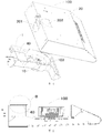
Fig. 1 is an exploded view of a range hood according to an embodiment of the present disclosure, in which the outer switching cover plate is located in a second position; -
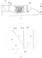
Fig. 2 is a side sectional view of a range hood according to an embodiment of the present disclosure; -
Fig. 3 is an enlarged view of A region ofFig. 2 ; -
Fig. 4 is an exploded view of a range hood according to an embodiment of the present disclosure, in which the outer switching cover plate is located in a first position; -
Fig. 5 is a side sectional view of a range hood according to an embodiment of the present disclosure, in which the outer switching cover plate is located in a first position; -
Fig. 6 is an enlarged view of B region ofFig. 5 ; -
Fig. 7 is an exploded view of a range hood according to an embodiment of the present disclosure, in which the outer switching cover plate is located in a second position; -
Fig. 8 is a schematic partially sectioned perspective view of a range hood according to an embodiment of the present disclosure; -
Fig. 9 is a schematic partially sectioned perspective view of a range hood according to an embodiment of the present disclosure; -
Fig. 10 is a schematic view of an outer switching cover plate of a range hood according to an embodiment of the present disclosure; -
Fig. 11 is a schematic perspective view of a volute casing of a range hood according to an embodiment of the present disclosure; -
Fig. 12 is an enlarged view of C region ofFig. 11 ; -
Fig. 13 is a schematic perspective view of a range hood according to an embodiment of the present invention; -
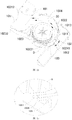
Fig. 14 is a schematic perspective view of a volute casing of the range hood shown inFig. 13 , in which the inner switching cover plate is located in a closed position; -
Fig. 15 is an enlarged view of D region ofFig. 14 ; -
Fig. 16 is a bottom view of a volute casing of the range hood shown inFig. 13 , in which the inner switching cover plate is located in a closed position; -
Fig. 17 is an enlarged view of E region ofFig. 16 ; -
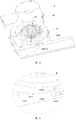
Fig. 18 is a schematic top perspective view of a volute casing of the range hood shown inFig. 13 , in which the inner switching cover plate is located in an opened position; -
Fig. 19 is an enlarged view of F region ofFig. 18 ; -
Fig. 20 is a schematic bottom view of a volute casing of the range hood shown inFig. 13 , in which the inner switching cover plate is located in an opened position; -
Fig. 21 is an enlarged view of G region ofFig. 20 ; -
Fig. 22 is a schematic top view of a volute casing of a range hood according to another embodiment of the present invention; -
Fig. 23 is a schematic bottom view of a volute casing of a range hood according to another embodiment of the present invention; -
Fig. 24 is a schematic view of an inner switching cover plate of a volute casing according to another embodiment of the present invention; -
Fig. 25 is an enlarged view of H region ofFig. 24 . -
-
range hood 100,volute casing 1 -
volute casing body 10,outer air outlet 105,inner air outlet 104 -
bottom plate 101,chute 1011, first position-restrictingcolumn 1012, second position-restrictingcolumn 1013, first position-restrictingboss 1014, second position-restrictingboss 1015, -
side encasing plate 102, first position-restrictinggroove 1021, second position-restrictinggroove 1022, firstside encasing plate 1023,first end 10231,second end 10232, secondside encasing plate 1024,first end 10241,second end 10242, snappinggroove 1025, - inner switching
cover plate 103,body 1031,operation portion 1032, snappingprojection 1033, first position-restrictinghole 1034, second position-restrictinghole 1035,first end 1036,second end 1037, - outer switching
cover plate 40,plate body 401,pivot 402, catchingjaw 403,drainage surface 404, -
housing 20, firstouter air vent 201, secondouter air vent 202,inner air vent 203, cover plate position-restrictinghole 204,top wall plate 205,rear wall plate 206,side wall plate 207, -
fan wheel 30, outer air vent seal-plate 41, - up-down direction I, front-rear direction J.
- Embodiments of the present disclosure will be described in detail and examples of the embodiments will be illustrated in the drawings, where same or similar reference numerals are used to indicate same or similar members or members with same or similar functions. The embodiments described herein with reference to drawings are explanatory, which are used to illustrate the present disclosure, but shall not be construed to limit the present disclosure.
- The
range hood 100 according to embodiments of the present disclosure is described with reference toFig. 1-25 . As shown inFig. 1-25 , therange hood 100 according to embodiments of the present disclosure includes ahousing 20, avolute casing 1, afan wheel 30 and an outer switchingcover plate 40. - The
housing 20 is formed with a firstouter air vent 201 and a secondouter air vent 202 therein. Thevolute casing 1 is disposed within thehousing 20, and includes avolute casing body 10. Thevolute casing body 10 includes abottom plate 101, a top plate and aside encasing plate 102 disposed between thebottom plate 101 and the top plate. In this embodiment, the top plate of thevolute casing body 10 is formed by a part of thetop wall plate 205 of thehousing 20. Thevolute casing body 10 is formed with anouter air outlet 105 communicated with the firstouter air vent 201 and the secondouter air vent 202, an opening direction of theouter air outlet 105 is substantially orthogonal to that of secondouter air vent 202. Herein, it should be understood broadly, for example, an angle between the opening direction of theouter air outlet 105 and the opening direction of secondouter air vent 202 may be in the range of (90±10) degrees. Thefan wheel 30 is disposed in thevolute casing 1, and may be actuated by an electric motor (not shown). - The outer switching
cover plate 40 may be disposed on thevolute casing 1 or thehousing 20 and movable between a first position (as shown inFig. 4 and Fig. 5 ), in which the firstouter air vent 201 is opened by the outer switchingcover plate 40 and the secondouter air vent 202 is closed by the outer switchingcover plate 40, and a second position (as shown inFig. 7 andFig. 8 ), in which the firstouter air vent 201 is closed by the outer switchingcover plate 40 and the secondouter air vent 202 is opened by the outer switchingcover plate 40. An angle α between the outer switchingcover plate 40 in the second position and the opening direction of the secondouter air vent 202 is greater than 0 degree and less than 90 degrees. - In other words, the outer switching
cover plate 40 may be moved between the first position in which theouter air outlet 105 is communicated with the firstouter air vent 201 and separated from the secondouter air vent 202 and the second position in which theouter air outlet 105 is separated from the firstouter air vent 201 and communicated with the secondouter air vent 202. In the second position, the outer switchingcover plate 40 is tilted relative to the opening direction S2 of the secondouter air vent 202, the angle α between them is greater than 0 degree and less than 90 degrees. More preferably, the angle α is equal to or greater than 30 degrees and equal to or less than 60 degrees. - In some embodiments, an opening direction S1 of the first
outer air vent 201 is substantially orthogonal to the opening direction S2 of the secondouter air vent 202. - In the following, unless specified otherwise, the first
outer air vent 201 is formed in arear wall plate 206 of thehousing 20 and opened backwards, and the secondouter air vent 202 is formed in atop wall plate 205 of thehousing 20 and opened upwards, which is taken for example. Therefore, the firstouter air vent 201 also may be called a rear outer air vent, and the secondouter air vent 202 also may be called an upper outer air vent. It should be understood that the firstouter air vent 201 may be formed in aside wall plate 207 of thehousing 20 and the secondouter air vent 202 may be formed in thetop wall plate 205 of thehousing 20. Alternatively, the firstouter air vent 201 may be formed in theside wall plate 207 of thehousing 20 and the secondouter air vent 202 may be formed in therear wall plate 206 of thehousing 20. - The
range hood 100 according to embodiments of the present disclosure may discharge air outdoors through the firstouter air vent 201 or the secondouter air vent 202. When the outer switchingcover plate 40 opens the firstouter air vent 201 and closes the secondouter air vent 202, therange hood 100 may discharge air backwards through the firstouter air vent 201. When the outer switchingcover plate 40 opens the secondouter air vent 202 and closes the firstouter air vent 201, therange hood 100 may discharge air upwards through the secondouter air vent 202. - In the second position, the outer switching
cover plate 40 is disposed obliquely, i.e. the angle α between the outer switchingcover plate 40 and the opening direction S2 (an upward direction inFig. 3 ) of the secondouter air vent 202 is greater than 0 degree and less than 90 degrees. Thus, the outer switchingcover plate 40 may form a drainage slope to guide air to flow upwards and discharge air through the secondouter air vent 202. It is possible to prevent air streams from turning through 90 degrees because the outer switchingcover plate 40 is parallel to the second outer air vent 202 (i.e. perpendicular to the opening direction S1 of the firstouter air vent 201 and an air stream discharged from the outer air outlet 105) in the related art, which may greatly reduce the flow loss of the air stream, improve the efficiency of the fan wheel, and reduce a vortex region in order to reduce aerodynamic noise. That is, the outer switchingcover plate 40 in the second position is further used as a drainage plate. - With the
range hood 100 according to embodiments of the present disclosure, by disposing the outer switchingcover plate 40 in the second position obliquely relative to the secondouter air vent 202, the outer switchingcover plate 40 may form a drainage slope to guide the air to flow upwards to prevent air streams from turning through 90 degrees. Thus, it is possible to reduce the flow loss of the stream, improve the efficiency of the fan wheel, and reduce the vortex region in order to reduce aerodynamic noise. - Therefore, the
range hood 100 according to embodiments of the present disclosure has advantages of less loss of air volume and air pressure, a high efficiency of the fan wheel and less aerodynamic noise. - The
range hood 100 according to some specific embodiments of the present disclosure is described below. - As shown in
Figs. 1-12 , in some specific embodiments, therange hood 100 includes ahousing 20, avolute casing 1, afan wheel 30 and an outer switchingcover plate 40. - The
volute casing 1 includes avolute casing body 10, and thevolute casing body 10 includes abottom plate 101, a top plate and aside encasing plate 102 disposed between thebottom plate 101 and the top plate. The outer switchingcover plate 40 is disposed on theside encasing plate 102 and pivotable between the first position and the second position. - The top plate of the
volute casing body 10 may be formed by a part of thetop wall plate 205 of thehousing 20. - As shown in
Figs. 10-12 , the outer switchingcover plate 40 includes aplate body 401, and apivot 402 and a catchingjaw 403 disposed on theplate body 401. Theside encasing plate 102 is formed with a snappinggroove 1025, which is opened upwards. Thepivot 402 is rotatably fitted within the snappinggroove 1025, so that the outer switchingcover plate 40 may be rotatably mounted on theside encasing plate 102. - A first
free end 10232 of two free ends of theside encasing plate 102 is formed with a snappinggroove 1025 therein, and a secondfree end 10242 of the two free ends of theside encasing plate 102 is formed with a snappinggroove 1025 therein. There are twopivots 402 disposed on theplate body 401, one of thepivots 402 is rotatably fitted within the snappinggroove 1025 in the firstfree end 10232, and the other one of thepivots 402 is rotatably fitted within the snappinggroove 1025 in the secondfree end 10242. - As shown in
Figs. 1 ,4-6 ,8-10 , thehousing 20 is formed with a cover plate position-restrictinghole 204 therein. The catchingjaw 403 is engaged within the cover plate position-restrictinghole 204 in the first position. Thus, the outer switchingcover plate 40 may be stably maintained in the first position, in order to prevent theouter air outlet 105 from being closed when theouter air outlet 105 is used to discharge air outdoors. - The cover plate position-restricting
hole 204 may be a through hole, i.e. the cover plate position-restrictinghole 204 may penetrate through thetop wall plate 205 of thehousing 20 in an up-down direction. There may be a plurality of the catchingjaws 403 and a plurality of the cover plate position-restrictingholes 204. A plurality of catchingjaws 403 may be engaged within a plurality of the cover plate position-restrictingholes 204 in one-to-one correspondence in the first position. Thus, the outer switchingcover plate 40 may be held stably in the first position. - The outer switching
cover plate 40 may be a flat plate or a curved plate. The outer switchingcover plate 40 is disposed obliquely in the second position so that the outer switchingcover plate 40 may form a drainage slope. That is, in the second position, a surface of the outer switchingcover plate 40 facing an air stream discharged from theouter air outlet 105 may form adrainage surface 404. - As described above, in the second position, the angle between the outer switching
cover plate 40 and an exit direction of the secondouter air vent 202 is greater than 0 degree and less than 90 degrees, more preferably, equal to or greater than 30 degrees and less than 60 degrees, i.e., the angle between the outer switchingcover plate 40 and thebottom plate 101 is equal to or greater than 120 degrees and equal to or less than 150 degrees. Thus, it is possible to further reduce the flow loss of the air stream, improve the efficiency of the fan wheel, and further reduce the vortex region in order to further reduce aerodynamic noise. - In the above embodiments, the outer switching
cover plate 40 may be pivotably disposed on theside encasing plate 102, and theouter air outlet 105 is opened backwards and upwards. Thus, in the first position, the outer switchingcover plate 40 opens a rear opening of theouter air outlet 105 and the first outer air vent 201 (i.e. the rear opening of theouter air outlet 105 is communicated with the first outer air vent 201), while the outer switchingcover plate 40 closes an upper opening of theouter air outlet 105 and the second outer air vent 202 (i.e. the upper opening of theouter air outlet 105 is separated from the second outer air vent 202). In the second position, the outer switchingcover plate 40 closes the rear opening of theouter air outlet 105 and the first outer air vent 201 (i.e. the rear opening of theouter air outlet 105 is separated from the first outer air vent 201), while the outer switchingcover plate 40 opens the upper opening of theouter air outlet 105 and the second outer air vent 202 (i.e. the upper opening of theouter air outlet 105 is communicated with the second outer air vent 202). - The
range hood 100 according to an embodiment of the present invention will be described below with reference toFigs. 13-25 . As shown inFigs. 13-25 , therange hood 100 includes ahousing 20, avolute casing 1, afan wheel 30, an outer switchingcover plate 40 and an outer air vent seal-plate 41. - As shown in
Fig. 13 , thehousing 20 is formed with a firstouter air vent 201, a secondouter air vent 202 and aninner air vent 203 therein. As shown inFig. 14 , thevolute casing 1 includes avolute casing body 10 and an innerswitching cover plate 103. Thevolute casing body 10 includes abottom plate 101, a top plate and aside encasing plate 102 disposed between thebottom plate 101 and the top plate. Thevolute casing 1 is formed with anouter air outlet 105 communicated with the firstouter air vent 201 and the secondouter air vent 202, and aninner air outlet 104 communicated with theinner air vent 203. - The inner
switching cover plate 103 is movable between an opened position, in which theinner air outlet 104 is opened by the innerswitching cover plate 103, and a closed position, in which theinner air outlet 104 is closed by the innerswitching cover plate 103. In the opened position, the outer air vent seal-plate 41 seals an opened one of the firstouter air vent 201 and the secondouter air vent 202. - In other words, in this embodiment, the
range hood 100 has three air discharging modes: an inward air discharging mode of discharging air indoors from theinner air outlet 104 and theinner air vent 203, a backward air discharging mode of discharging air outdoors from anouter air outlet 105 and the firstouter air vent 201, and an upward air discharging mode of discharging air outdoors from theouter air outlet 105 and the secondouter air vent 202. - For example, in the inward air discharging mode, the inner
switching cover plate 103 is in the opened position. If the outer switchingcover plate 40 is in the first position (i.e. the firstouter air vent 201 is opened and the secondouter air vent 202 is closed), the outer air vent seal-plate 41 needs to seal the firstouter air vent 201. If the outer switchingcover plate 40 is in the second position (i.e. the firstouter air vent 201 is closed and the secondouter air vent 202 is opened), the outer air vent seal-plate 41 needs to seal the secondouter air vent 202. - In the backward air discharging mode, the inner
switching cover plate 103 is in the closed position, and the outer switchingcover plate 40 is in the first position (i.e. the firstouter air vent 201 is opened and the secondouter air vent 202 is closed). - In the upward air discharging mode, the inner
switching cover plate 103 is in the closed position, and the outer switchingcover plate 40 is in the second position (i.e. the firstouter air vent 201 is closed and the secondouter air vent 202 is opened). - Preferably, a shape of the inner
switching cover plate 30 is configured such that in the closed position, a complete volute casing curved surface is formed by theside encasing plate 102 and a part of the innerswitching cover plate 103 corresponding to theinner air outlet 104. More preferably, theinner air outlet 104 is formed in a helical curved surface of the volute casing curved surface. - That is, in the closed position, a part of the inner
switching cover plate 103 for closing theinner air outlet 104 forms a complete volute casing curved surface with theside encasing plate 102. In other words, theinner air outlet 104 may be formed by cutting off a part of theside encasing plate 102, the part of theside encasing plate 102 is equivalent to the innerswitching cover plate 103 or the part of the innerswitching cover plate 103 corresponding to theinner air outlet 104. - According to the present invention, the inner
switching cover plate 103 is used to open or close theinner air outlet 104 by providing the innerswitching cover plate 103 movable between the opened position and the closed position. A complete volute casing curved surface is formed by a part of the innerswitching cover plate 30 in the closed position corresponding to theinner air outlet 104 and theside encasing plate 102. Therefore, when therange hood 100 discharges air outdoors, the volute casing curved surface of thevolute casing 1 may remain complete and will not be broken by theinner air outlet 104, so as to greatly reduce the flow loss of the air stream and improve the efficiency of the fan wheel of therange hood 100. - Moreover, the length of the air flue between the
inner air outlet 104 and theinner air vent 203 may be reduced or there is even no need for an air flue by providing the innerswitching cover plate 103 for opening or closing theinner air outlet 104. Therefore, it is possible to reduce the flow loss of the air stream and improve the efficiency of the fan wheel of therange hood 100. - As shown in
Fig. 13 , in one embodiment, theside encasing plate 102 includes a firstside encasing plate 1023 and a secondside encasing plate 1024. Afirst end 10231 of the firstside encasing plate 1023 is spaced apart from afirst end 10241 of the secondside encasing plate 1024 so as to define theinner air outlet 104, and asecond end 10232 of the firstside encasing plate 1023 is spaced apart from asecond end 10242 of the secondside encasing plate 1024 so as to define theouter air outlet 105. - Specifically, a front end of the first
side encasing plate 1023 is spaced apart from a front end of the secondside encasing plate 1024 so as to form theinner air outlet 104, and a rear end of the firstside encasing plate 1023 is spaced apart from a rear end of the secondside encasing plate 1024 so as to form theouter air outlet 105. The front-rear direction is shown by an arrow J inFig. 22 . - As shown in
Fig. 18 andFig. 22 , in one specific embodiment of the present invention, theinner air outlet 104 is away from theouter air outlet 105 in a circumferential direction of theside encasing plate 102. - As shown in
Fig. 15 andFig. 19 , thefirst end 10231 of the firstside encasing plate 1023 is formed with a first position-restrictinggroove 1021, and thefirst end 10241 of the secondside encasing plate 1024 is formed with a second position-restrictinggroove 1022. Thefirst end 1036 of the innerswitching cover plate 103 is engaged within the first position-restrictinggroove 1021 in the closed position, and thesecond end 1037 of the innerswitching cover plate 103 is engaged within the second position-restrictinggroove 1022 in the opened position. - The
first end 10231 of the firstside encasing plate 1023 is formed with the first position-restrictinggroove 1021 therein and thefirst end 1036 of the innerswitching cover plate 103 is engaged within the first position-restrictinggroove 1021 in the closed position, such that theinner air outlet 104 may be completely closed so as to prevent the air from leaking through theinner air outlet 104. - The
first end 10241 of the secondside encasing plate 1024 is formed with the second position-restrictinggroove 1022 therein and thesecond end 1037 of the innerswitching cover plate 103 is engaged within the second position-restrictinggroove 1022 in the opened position, such that the innerswitching cover plate 103 may remain in the opened position stably. Thus, theinner air outlet 104 may be prevented from being closed when air is discharged indoors. - Advantageously, as shown in
Fig. 14 andFig. 18 , the shape of the innerswitching cover plate 103 is adapted to the shape of a part of theside encasing plate 102. The innerswitching cover plate 103 is attached to theside encasing plate 102 when moving in the circumferential direction of theside encasing plate 102. - As shown in
Figs. 16-18 , thebottom plate 101 is formed with achute 1011 therein. The innerswitching cover plate 103 is slidably fitted within thechute 1011, so that the innerswitching cover plate 103 is disposed on thebottom plate 101 and movable between the opened position in which theinner air outlet 104 is opened and the closed position in which theinner air outlet 104 is closed. - In some embodiments, the
chute 1011 may penetrate through thebottom plate 101 in a thickness direction of thebottom plate 101. The innerswitching cover plate 103 is provided with a snappingprojection 1033 on thebottom plate 101 and anoperation portion 1032 below thebottom plate 101 for moving the innerswitching cover plate 103 along thechute 1011. In other words, thebottom plate 101 may be clamped between the snappingprojection 1033 and theoperation portion 1032, and a user may drive the innerswitching cover plate 103 to move by holding theoperation portion 1032. - As shown in
Figs. 16-17 , and20-21 , thebottom plate 101 is provided with a first position-restrictingboss 1014 and a second position-restrictingboss 1015 thereon, theoperation portion 1032 is formed with a first position-restrictinghole 1034 and a second position-restrictinghole 1035 therein, the first position-restrictingboss 1014 is engaged within the first position-restrictinghole 1034 in the closed position, and the second position-restrictingboss 1015 is engaged within the second position-restrictinghole 1035 in the opened position. Therefore, the innerswitching cover plate 103 may remain in the closed position or the opened position stably, such that theinner air outlet 104 may be prevented from being opened when air is discharged outdoors and prevented from being closed when air is discharged indoors. - Specifically, both of the first position-restricting
boss 1014 and the second position-restrictingboss 1015 are disposed on the lower surface of thebottom plate 101, the first position-restrictinghole 1034 and the second position-restrictinghole 1035 both penetrate through theoperation portion 1032 in the up-down direction. The up-down direction is shown by an arrow I inFig. 2 andFig. 23 . - As shown in
Figs. 18-19 , in one embodiment of the present invention, thebottom plate 101 is provided with a first position-restrictingcolumn 1012 and a second position-restrictingcolumn 1013 thereon, which may limit the first switchingcover plate 103 to move between theside encasing plate 102 and the first and second position-restrictingcolumns cover plate 103 may be prevented from swinging in a direction away from theside encasing plate 102 to perform a guiding function when theinner air outlet 104 is opened or closed. - Specifically, as shown in
Fig. 19 , the front wall of the second position-restrictinggroove 1022 is rolled up in a direction away from the second position-restrictinggroove 1022 so as to form the second position-restrictingcolumn 1013. - In the specification, it is to be understood that terms such as "central," "longitudinal," "lateral," "length," "width," "thickness," "upper," "lower," "front," "rear," "left," "right," "vertical," "horizontal," "top," "bottom," "inner," "outer," "clockwise," "counterclockwise," "axial," "radial," and "circumference" should be construed to refer to the orientation as then described or as shown in the drawings under discussion. These relative terms are for convenience of description and do not require that the present disclosure be constructed or operated in a particular orientation.
- In addition, terms such as "first" and "second" are used herein for purposes of description and are not intended to indicate or imply relative importance or significance or to imply the number of indicated technical features. Thus, the feature defined with "first" and "second" may include one or more of this feature. In the description of the present disclosure, "a plurality of' means at least two, e.g. two, three and so on, unless specified otherwise.
- In the present disclosure, unless specified or limited otherwise, the terms "mounted," "connected," "coupled," "fixed" and the like are used broadly, and may be, for example, fixed connections, detachable connections, or integral connections; may also be mechanical or electrical connections; may also be direct connections or indirect connections via intervening structures; may also be inner communications of two elements, which may be understood by those skilled in the art according to specific situations.
- In the present disclosure, unless specified or limited otherwise, a structure in which a first feature is "on" or "below" a second feature may include an embodiment in which the first feature is in direct contact with the second feature, and may also include an embodiment in which the first feature and the second feature are not in direct contact with each other, but are contacted via an additional feature formed therebetween. Furthermore, a first feature "on," "above," or "on top of' a second feature may include an embodiment in which the first feature is right or obliquely "on," "above," or "on top of' the second feature, or just means that the first feature is at a height higher than that of the second feature; while a first feature "below," "under," or "on bottom of' a second feature may include an embodiment in which the first feature is right or obliquely "below," "under," or "on bottom of' the second feature, or just means that the first feature is at a height lower than that of the second feature.
- Reference throughout this specification to "an embodiment," "some embodiments," "an example," "a specific example," or "some examples," means that a particular feature, structure, material, or characteristic described in connection with the embodiment or example is included in at least one embodiment or example of the present disclosure. Thus, the appearances of the phrases in various places throughout this specification are not necessarily referring to the same embodiment or example of the present disclosure. Furthermore, the particular features, structures, materials, or characteristics may be combined in any suitable manner in one or more embodiments or examples. In addition, those skilled in the art may combine and composite different embodiments or examples and features of various embodiments or examples embodiment described in the description with no conflicting situation.
Claims (13)
- A range hood (100), comprising:a housing (20) defining a first outer air vent (201) and a second outer air vent (202);a volute casing (1) disposed within the housing (20), and comprising a volute casing body (10) having a bottom plate (101), a top plate and a side encasing plate (102) disposed between the bottom plate (101) and the top plate, the volute casing body (10) defining an outer air outlet (105) communicated with the first outer air vent (201) and the second outer air vent (202), and an opening direction of the outer air outlet (105) being orthogonal to that of the second outer air vent (202);a fan wheel (30) disposed within the volute casing body (10);an outer switching cover plate (40) disposed on one of the volute casing (1) and the housing (20) and movable between a first position, in which the first outer air vent (201) is opened by the outer switching cover plate (40) and the second outer air vent (202) is closed by the outer switching cover plate (40), and a second position, in which the first outer air vent (201) is closed by the outer switching cover plate (40) and the second outer air vent (202) is opened by the outer switching cover plate (40), an angle α between the outer switching cover plate (40) in the second position and the opening direction of the second outer air vent (202) being greater than 0 degree and less than 90 degrees; andwhereby the range hood (100) further comprises an outer air vent seal-plate (41), wherein the housing (20) defines an inner air vent (203), the volute casing body (10) defines an inner air outlet (104) communicated with the inner air vent (203), the volute casing (1) further comprises an inner switching cover plate (103) movable between an opened position, in which the inner air outlet (104) is opened by the inner switching cover plate (103), and a closed position, in which the inner air outlet (104) is closed by the inner switching cover plate (103), in which the outer air vent seal-plate (41) seals an opened one of the first outer air vent (201) and the second outer air vent (202) in the opened position.
- The range hood (100) according to claim 1, wherein an opening direction of the first outer air vent (201) is orthogonal to the opening direction of the second outer air vent (202).
- The range hood (100) according to claim 1 or 2, wherein the angle α is equal to or greater than 30 degrees and equal to or less than 60 degrees.
- The range hood (100) according to any one of claims 1-3, wherein the outer switching cover plate (40) is disposed on the side encasing plate (102) and pivotable between the first position and the second position.
- The range hood (100) according to claim 4, wherein a snapping groove (1025) is formed in the side encasing plate (102), and the outer switching cover plate (40) comprises a plate body (401) and a pivot (402) which is disposed on the plate body (401) and rotatably fitted within the snapping groove (1025).
- The range hood (100) according to any one of claims 1-5, wherein the first outer air vent (201) is formed in a rear wall plate (206) of the housing (20), and the second outer air vent (202) is formed in a top wall plate (205) of the housing (20).
- The range hood (100) according to any one of claims 1-6, wherein the outer switching cover plate (40) is a flat plate or a curved plate.
- The range hood (100) according to any one of claims 1-7, wherein the housing (20) defines a cover plate position-restricting hole (204), the outer switching cover plate (40) comprises a plate body (401) and a catching jaw (403) which is disposed on the plate body (401) and engaged within the cover plate position-restricting hole (204) in the first position.
- The range hood (100) according to claim 1, wherein a shape of the inner switching cover plate (103) is configured such that a complete volute casing curved surface is formed by the side encasing plate and a part of the inner switching cover plate (103) in the closed position corresponding to the inner air outlet (104).
- The range hood (100) according to claim 9, wherein the inner air outlet (104) is formed in a helical curved surface of the volute casing curved surface.
- The range hood (100) according to claim 1, wherein the side encasing plate (102) comprises a first side encasing plate (1023) and a second side encasing plate (1024),
wherein a first end (10231) of the first side encasing plate (1023) is spaced apart from a first end (10241) of the second side encasing plate (1024) such that the inner air outlet (104) is defined by the first end (10231) of the first side encasing plate (1023), the first end (10241) of the second side encasing plate (1024), the top plate and the bottom plate (101),
wherein a second end (10232) of the first side encasing plate (1023) is spaced apart from a second end (10242) of the second side encasing plate (1024) such that the outer air outlet (105) is defined by the second end (10232) of the first side encasing plate (1023), the second end (10242) of the second side encasing plate (1024), the top plate and the bottom plate (101),
specially, a first position-restricting groove (1021) is formed in the first end (10231) of the first side encasing plate (1023), a second position-restricting groove (1022) is formed in the first end (10241) of the second side encasing plate (1024), the first end (1036) of the inner switching cover plate (103) is engaged within the first position-restricting groove (1021) in the closed position, and the second end (1037) of the inner switching cover plate (103) is engaged within the second position-restricting groove (1022) in the opened position. - The range hood (100) according to claim 9, wherein the inner switching cover plate (103) clings to the side encasing plate closely during moving between the opened position and the closed position,
specially, the bottom plate (101) defines a chute (1011) penetrating therethrough in a thickness direction thereof, the inner switching cover plate (103) is slidably fitted within the chute (1011), wherein the inner switching cover plate (103) is provided with a snapping projection (1033) on the bottom plate (101) and an operation portion (1032) which is below the bottom plate (101) for moving the inner switching cover plate (103) along the chute (1011). - The range hood (100) according to claim 12, wherein the bottom plate (101) is provided with a first position-restricting column (1012) and a second position-restricting column (1013) thereon, the snapping projection (1033) is abutted against the first position-restricting column (1012) in the closed position, and the snapping projection (1033) is abutted against the second position-restricting column (1013) in the opened position; and/or
wherein the bottom plate (101) is provided with a first position-restricting boss (1014) and a second position-restricting boss (1015) thereon, the operation portion (1032) defines a first position-restricting hole (1034) and a second position-restricting hole (1035) therein, wherein the first position-restricting boss (1014) is engaged within the first position-restricting hole (1034) in the closed position, and the second position-restricting boss (1015) is engaged within the second position-restricting hole (1035) in the opened position.
Applications Claiming Priority (3)
| Application Number | Priority Date | Filing Date | Title |
|---|---|---|---|
| CN201420526495.7U CN204313343U (en) | 2014-09-12 | 2014-09-12 | Range hood and spiral case thereof |
| CN201410466253.8A CN104501244B (en) | 2014-09-12 | 2014-09-12 | Range hood and its spiral case |
| PCT/CN2014/091295 WO2016037414A1 (en) | 2014-09-12 | 2014-11-17 | Range hood and volute thereof |
Publications (3)
| Publication Number | Publication Date |
|---|---|
| EP3112759A1 EP3112759A1 (en) | 2017-01-04 |
| EP3112759A4 EP3112759A4 (en) | 2017-10-25 |
| EP3112759B1 true EP3112759B1 (en) | 2019-01-30 |
Family
ID=55458301
Family Applications (1)
| Application Number | Title | Priority Date | Filing Date |
|---|---|---|---|
| EP14885061.3A Not-in-force EP3112759B1 (en) | 2014-09-12 | 2014-11-17 | Range hood and volute thereof |
Country Status (3)
| Country | Link |
|---|---|
| US (1) | US10060634B2 (en) |
| EP (1) | EP3112759B1 (en) |
| WO (1) | WO2016037414A1 (en) |
Families Citing this family (14)
| Publication number | Priority date | Publication date | Assignee | Title |
|---|---|---|---|---|
| USD743520S1 (en) * | 2013-06-20 | 2015-11-17 | Broan-Nutone Llc | Range hood |
| USD826392S1 (en) * | 2015-06-11 | 2018-08-21 | Broan-Nutone Llc | Vent hood |
| EP3348912B1 (en) * | 2015-09-08 | 2021-05-12 | Guangdong Midea Kitchen Appliances Manufacturing Co., Ltd. | Range hood |
| CN112177982A (en) * | 2019-07-01 | 2021-01-05 | 青岛经济技术开发区海尔热水器有限公司 | Noise reduction air duct and gas water heater |
| USD948699S1 (en) * | 2020-03-27 | 2022-04-12 | Foshan Shunde Midea Washing Appliances Manufacturing Co., Ltd. | Range hood |
| CN114076113B (en) * | 2020-08-21 | 2025-06-06 | 宁波奥克斯电气有限公司 | A volute assembly structure and air conditioner |
| JP7459750B2 (en) | 2020-09-30 | 2024-04-02 | ニデック株式会社 | Air Flow Control Device |
| CN112377462B (en) * | 2020-10-13 | 2021-12-10 | 宁波方太厨具有限公司 | A diversion device, a centrifugal fan and a range hood using the diversion device |
| CN113551321B (en) * | 2021-07-13 | 2022-07-26 | 珠海格力电器股份有限公司 | Support structure for dehumidifier and dehumidifier with support structure |
| CN116085840A (en) * | 2021-11-08 | 2023-05-09 | 佛山市顺德区美的洗涤电器制造有限公司 | Thin range hood |
| CN115435362B (en) * | 2022-09-01 | 2024-11-15 | 杭州老板电器股份有限公司 | A reversing flow guide device for air outlet of range hood and integrated stove |
| CN116241920A (en) * | 2023-01-04 | 2023-06-09 | 芜湖美的智能厨电制造有限公司 | Ventilation modules and range hoods |
| CN115854401A (en) * | 2023-01-04 | 2023-03-28 | 芜湖美的智能厨电制造有限公司 | range hood |
| CN116241919A (en) * | 2023-01-04 | 2023-06-09 | 芜湖美的智能厨电制造有限公司 | Connection pipe and range hood |
Family Cites Families (22)
| Publication number | Priority date | Publication date | Assignee | Title |
|---|---|---|---|---|
| US2297049A (en) | 1941-06-12 | 1942-09-29 | Robert E Cotton | Blower structure |
| US2839987A (en) * | 1954-03-03 | 1958-06-24 | Emerson Pryne Company | Ventilating hood construction |
| US2874628A (en) * | 1955-05-09 | 1959-02-24 | Emerson Pryne Company | Removable ventilating hood construction |
| US3098423A (en) * | 1961-02-10 | 1963-07-23 | Anthony J Giannini | Adjustable exhaust hood |
| US3194146A (en) | 1962-11-05 | 1965-07-13 | Preway Inc | Damper device and hood including damper |
| US3145643A (en) * | 1963-08-27 | 1964-08-25 | Lau Blower Co | Range hood |
| US3359885A (en) * | 1966-01-17 | 1967-12-26 | Preway Inc | Vent hood |
| US3362319A (en) * | 1966-01-19 | 1968-01-09 | Home Metal Prod Co | Ventilating hood with detachable bonnet |
| US3589266A (en) * | 1969-06-24 | 1971-06-29 | Sutton James R | Air circulating stove hood |
| US4089328A (en) | 1976-11-02 | 1978-05-16 | Futurumverken Ab | Kitchen ventilator |
| JPS58187599A (en) * | 1982-04-26 | 1983-11-01 | Matsushita Electric Ind Co Ltd | flow direction control device |
| KR920002386Y1 (en) * | 1990-03-30 | 1992-04-10 | 삼성전자 주식회사 | Guide to supplying cold air in the refrigerator |
| US5738083A (en) | 1995-01-12 | 1998-04-14 | Turboaire S.P.A. | Flow deflector for filtration hood |
| US6073305A (en) * | 1998-03-02 | 2000-06-13 | Hesskamp; Scott | Debris blower |
| DE19809559A1 (en) * | 1998-03-05 | 1999-09-09 | Bosch Siemens Hausgeraete | Extractor hood |
| CN2416417Y (en) | 1999-10-08 | 2001-01-24 | 顾建军 | Induced draft fan |
| CN2789658Y (en) * | 2005-04-04 | 2006-06-21 | 顾建军 | Air exchanger |
| CN201476129U (en) | 2009-06-26 | 2010-05-19 | 佛山市樱顺卫厨用品有限公司 | Energy-saving highly-effective smoke exhaust ventilator |
| US20110036340A1 (en) * | 2009-08-17 | 2011-02-17 | Ming-Hung Chu | High efficiency range hood |
| DE102011000654A1 (en) | 2011-02-11 | 2012-08-16 | Miele & Cie. Kg | Extractor hood for a stove, a hob or the like |
| US9057527B2 (en) * | 2012-03-12 | 2015-06-16 | General Electric Company | Range hood appliance with combination recirculation and exterior venting options |
| CN204313343U (en) | 2014-09-12 | 2015-05-06 | 芜湖美的厨房电器制造有限公司 | Range hood and spiral case thereof |
-
2014
- 2014-11-17 EP EP14885061.3A patent/EP3112759B1/en not_active Not-in-force
- 2014-11-17 US US15/123,709 patent/US10060634B2/en active Active
- 2014-11-17 WO PCT/CN2014/091295 patent/WO2016037414A1/en not_active Ceased
Also Published As
| Publication number | Publication date |
|---|---|
| EP3112759A1 (en) | 2017-01-04 |
| EP3112759A4 (en) | 2017-10-25 |
| WO2016037414A1 (en) | 2016-03-17 |
| US20170016629A1 (en) | 2017-01-19 |
| US10060634B2 (en) | 2018-08-28 |
Similar Documents
| Publication | Publication Date | Title |
|---|---|---|
| US10060634B2 (en) | Range hood and volute casing thereof | |
| CN104501244B (en) | Range hood and its spiral case | |
| US10969116B2 (en) | Range hood | |
| JP2021501851A5 (en) | ||
| US9855522B2 (en) | Air purifier | |
| WO2016037407A1 (en) | Volute for range hood and range hood provided with volute | |
| EP3348912B1 (en) | Range hood | |
| CN206817562U (en) | side-suction type range hood | |
| CN110686293B (en) | Fume exhaust fan | |
| EP3034951B1 (en) | Cooking device with hood | |
| CN120251553A (en) | Handheld fan head | |
| CN114396643B (en) | A type of integrated stove with a fast-reversing straight-vent structure | |
| CN104214809A (en) | Smoke exhaust ventilator | |
| CN106801903A (en) | side-suction type range hood | |
| US6991431B2 (en) | Ceiling fan blade | |
| KR101713194B1 (en) | Mixer installed improved heat effluence system | |
| JP5465069B2 (en) | Natural air supply unit | |
| CN107990392B (en) | A kind of range hood | |
| KR200476073Y1 (en) | Cartridge for cold water and hot water having step operation means of rotary click type | |
| CN110645612A (en) | grease pump | |
| US20120247451A1 (en) | Teppanyaki assembly available for sucking air by multiple angles | |
| CN111120265B (en) | Discharge structure of compressor and compressor having the same | |
| KR102269442B1 (en) | Cooking device | |
| CN204100515U (en) | Air purifier | |
| KR102099649B1 (en) | Air conditioner |
Legal Events
| Date | Code | Title | Description |
|---|---|---|---|
| PUAI | Public reference made under article 153(3) epc to a published international application that has entered the european phase |
Free format text: ORIGINAL CODE: 0009012 |
|
| STAA | Information on the status of an ep patent application or granted ep patent |
Free format text: STATUS: REQUEST FOR EXAMINATION WAS MADE |
|
| 17P | Request for examination filed |
Effective date: 20150914 |
|
| AK | Designated contracting states |
Kind code of ref document: A1 Designated state(s): AL AT BE BG CH CY CZ DE DK EE ES FI FR GB GR HR HU IE IS IT LI LT LU LV MC MK MT NL NO PL PT RO RS SE SI SK SM TR |
|
| AX | Request for extension of the european patent |
Extension state: BA ME |
|
| A4 | Supplementary search report drawn up and despatched |
Effective date: 20170922 |
|
| RIC1 | Information provided on ipc code assigned before grant |
Ipc: F04D 29/00 20060101ALI20170918BHEP Ipc: F04D 17/04 20060101ALI20170918BHEP Ipc: F04D 29/42 20060101ALI20170918BHEP Ipc: F24F 7/00 20060101ALI20170918BHEP Ipc: F24C 15/20 20060101AFI20170918BHEP Ipc: F04D 29/46 20060101ALI20170918BHEP Ipc: F04D 25/14 20060101ALI20170918BHEP |
|
| DAX | Request for extension of the european patent (deleted) | ||
| GRAP | Despatch of communication of intention to grant a patent |
Free format text: ORIGINAL CODE: EPIDOSNIGR1 |
|
| STAA | Information on the status of an ep patent application or granted ep patent |
Free format text: STATUS: GRANT OF PATENT IS INTENDED |
|
| RIC1 | Information provided on ipc code assigned before grant |
Ipc: F04D 29/46 20060101ALI20180810BHEP Ipc: F24C 15/20 20060101AFI20180810BHEP Ipc: F04D 29/00 20060101ALI20180810BHEP Ipc: F04D 17/04 20060101ALI20180810BHEP Ipc: F04D 29/42 20060101ALI20180810BHEP Ipc: F04D 25/14 20060101ALI20180810BHEP Ipc: F24F 7/00 20060101ALI20180810BHEP |
|
| INTG | Intention to grant announced |
Effective date: 20180829 |
|
| GRAS | Grant fee paid |
Free format text: ORIGINAL CODE: EPIDOSNIGR3 |
|
| GRAA | (expected) grant |
Free format text: ORIGINAL CODE: 0009210 |
|
| STAA | Information on the status of an ep patent application or granted ep patent |
Free format text: STATUS: THE PATENT HAS BEEN GRANTED |
|
| AK | Designated contracting states |
Kind code of ref document: B1 Designated state(s): AL AT BE BG CH CY CZ DE DK EE ES FI FR GB GR HR HU IE IS IT LI LT LU LV MC MK MT NL NO PL PT RO RS SE SI SK SM TR |
|
| REG | Reference to a national code |
Ref country code: GB Ref legal event code: FG4D |
|
| REG | Reference to a national code |
Ref country code: CH Ref legal event code: EP |
|
| REG | Reference to a national code |
Ref country code: AT Ref legal event code: REF Ref document number: 1093591 Country of ref document: AT Kind code of ref document: T Effective date: 20190215 |
|
| REG | Reference to a national code |
Ref country code: IE Ref legal event code: FG4D |
|
| REG | Reference to a national code |
Ref country code: DE Ref legal event code: R096 Ref document number: 602014040613 Country of ref document: DE |
|
| REG | Reference to a national code |
Ref country code: LT Ref legal event code: MG4D |
|
| REG | Reference to a national code |
Ref country code: NL Ref legal event code: MP Effective date: 20190130 |
|
| PG25 | Lapsed in a contracting state [announced via postgrant information from national office to epo] |
Ref country code: NO Free format text: LAPSE BECAUSE OF FAILURE TO SUBMIT A TRANSLATION OF THE DESCRIPTION OR TO PAY THE FEE WITHIN THE PRESCRIBED TIME-LIMIT Effective date: 20190430 Ref country code: FI Free format text: LAPSE BECAUSE OF FAILURE TO SUBMIT A TRANSLATION OF THE DESCRIPTION OR TO PAY THE FEE WITHIN THE PRESCRIBED TIME-LIMIT Effective date: 20190130 Ref country code: LT Free format text: LAPSE BECAUSE OF FAILURE TO SUBMIT A TRANSLATION OF THE DESCRIPTION OR TO PAY THE FEE WITHIN THE PRESCRIBED TIME-LIMIT Effective date: 20190130 Ref country code: PL Free format text: LAPSE BECAUSE OF FAILURE TO SUBMIT A TRANSLATION OF THE DESCRIPTION OR TO PAY THE FEE WITHIN THE PRESCRIBED TIME-LIMIT Effective date: 20190130 Ref country code: PT Free format text: LAPSE BECAUSE OF FAILURE TO SUBMIT A TRANSLATION OF THE DESCRIPTION OR TO PAY THE FEE WITHIN THE PRESCRIBED TIME-LIMIT Effective date: 20190530 Ref country code: SE Free format text: LAPSE BECAUSE OF FAILURE TO SUBMIT A TRANSLATION OF THE DESCRIPTION OR TO PAY THE FEE WITHIN THE PRESCRIBED TIME-LIMIT Effective date: 20190130 Ref country code: ES Free format text: LAPSE BECAUSE OF FAILURE TO SUBMIT A TRANSLATION OF THE DESCRIPTION OR TO PAY THE FEE WITHIN THE PRESCRIBED TIME-LIMIT Effective date: 20190130 Ref country code: NL Free format text: LAPSE BECAUSE OF FAILURE TO SUBMIT A TRANSLATION OF THE DESCRIPTION OR TO PAY THE FEE WITHIN THE PRESCRIBED TIME-LIMIT Effective date: 20190130 |
|
| REG | Reference to a national code |
Ref country code: AT Ref legal event code: MK05 Ref document number: 1093591 Country of ref document: AT Kind code of ref document: T Effective date: 20190130 |
|
| PG25 | Lapsed in a contracting state [announced via postgrant information from national office to epo] |
Ref country code: GR Free format text: LAPSE BECAUSE OF FAILURE TO SUBMIT A TRANSLATION OF THE DESCRIPTION OR TO PAY THE FEE WITHIN THE PRESCRIBED TIME-LIMIT Effective date: 20190501 Ref country code: BG Free format text: LAPSE BECAUSE OF FAILURE TO SUBMIT A TRANSLATION OF THE DESCRIPTION OR TO PAY THE FEE WITHIN THE PRESCRIBED TIME-LIMIT Effective date: 20190430 Ref country code: HR Free format text: LAPSE BECAUSE OF FAILURE TO SUBMIT A TRANSLATION OF THE DESCRIPTION OR TO PAY THE FEE WITHIN THE PRESCRIBED TIME-LIMIT Effective date: 20190130 Ref country code: RS Free format text: LAPSE BECAUSE OF FAILURE TO SUBMIT A TRANSLATION OF THE DESCRIPTION OR TO PAY THE FEE WITHIN THE PRESCRIBED TIME-LIMIT Effective date: 20190130 Ref country code: IS Free format text: LAPSE BECAUSE OF FAILURE TO SUBMIT A TRANSLATION OF THE DESCRIPTION OR TO PAY THE FEE WITHIN THE PRESCRIBED TIME-LIMIT Effective date: 20190530 Ref country code: LV Free format text: LAPSE BECAUSE OF FAILURE TO SUBMIT A TRANSLATION OF THE DESCRIPTION OR TO PAY THE FEE WITHIN THE PRESCRIBED TIME-LIMIT Effective date: 20190130 |
|
| PG25 | Lapsed in a contracting state [announced via postgrant information from national office to epo] |
Ref country code: AL Free format text: LAPSE BECAUSE OF FAILURE TO SUBMIT A TRANSLATION OF THE DESCRIPTION OR TO PAY THE FEE WITHIN THE PRESCRIBED TIME-LIMIT Effective date: 20190130 Ref country code: EE Free format text: LAPSE BECAUSE OF FAILURE TO SUBMIT A TRANSLATION OF THE DESCRIPTION OR TO PAY THE FEE WITHIN THE PRESCRIBED TIME-LIMIT Effective date: 20190130 Ref country code: DK Free format text: LAPSE BECAUSE OF FAILURE TO SUBMIT A TRANSLATION OF THE DESCRIPTION OR TO PAY THE FEE WITHIN THE PRESCRIBED TIME-LIMIT Effective date: 20190130 Ref country code: IT Free format text: LAPSE BECAUSE OF FAILURE TO SUBMIT A TRANSLATION OF THE DESCRIPTION OR TO PAY THE FEE WITHIN THE PRESCRIBED TIME-LIMIT Effective date: 20190130 Ref country code: CZ Free format text: LAPSE BECAUSE OF FAILURE TO SUBMIT A TRANSLATION OF THE DESCRIPTION OR TO PAY THE FEE WITHIN THE PRESCRIBED TIME-LIMIT Effective date: 20190130 Ref country code: SK Free format text: LAPSE BECAUSE OF FAILURE TO SUBMIT A TRANSLATION OF THE DESCRIPTION OR TO PAY THE FEE WITHIN THE PRESCRIBED TIME-LIMIT Effective date: 20190130 Ref country code: RO Free format text: LAPSE BECAUSE OF FAILURE TO SUBMIT A TRANSLATION OF THE DESCRIPTION OR TO PAY THE FEE WITHIN THE PRESCRIBED TIME-LIMIT Effective date: 20190130 |
|
| REG | Reference to a national code |
Ref country code: DE Ref legal event code: R097 Ref document number: 602014040613 Country of ref document: DE |
|
| PG25 | Lapsed in a contracting state [announced via postgrant information from national office to epo] |
Ref country code: SM Free format text: LAPSE BECAUSE OF FAILURE TO SUBMIT A TRANSLATION OF THE DESCRIPTION OR TO PAY THE FEE WITHIN THE PRESCRIBED TIME-LIMIT Effective date: 20190130 |
|
| PLBE | No opposition filed within time limit |
Free format text: ORIGINAL CODE: 0009261 |
|
| STAA | Information on the status of an ep patent application or granted ep patent |
Free format text: STATUS: NO OPPOSITION FILED WITHIN TIME LIMIT |
|
| PG25 | Lapsed in a contracting state [announced via postgrant information from national office to epo] |
Ref country code: AT Free format text: LAPSE BECAUSE OF FAILURE TO SUBMIT A TRANSLATION OF THE DESCRIPTION OR TO PAY THE FEE WITHIN THE PRESCRIBED TIME-LIMIT Effective date: 20190130 |
|
| 26N | No opposition filed |
Effective date: 20191031 |
|
| PGFP | Annual fee paid to national office [announced via postgrant information from national office to epo] |
Ref country code: DE Payment date: 20191115 Year of fee payment: 6 |
|
| PG25 | Lapsed in a contracting state [announced via postgrant information from national office to epo] |
Ref country code: SI Free format text: LAPSE BECAUSE OF FAILURE TO SUBMIT A TRANSLATION OF THE DESCRIPTION OR TO PAY THE FEE WITHIN THE PRESCRIBED TIME-LIMIT Effective date: 20190130 |
|
| PGFP | Annual fee paid to national office [announced via postgrant information from national office to epo] |
Ref country code: FR Payment date: 20191129 Year of fee payment: 6 |
|
| PG25 | Lapsed in a contracting state [announced via postgrant information from national office to epo] |
Ref country code: TR Free format text: LAPSE BECAUSE OF FAILURE TO SUBMIT A TRANSLATION OF THE DESCRIPTION OR TO PAY THE FEE WITHIN THE PRESCRIBED TIME-LIMIT Effective date: 20190130 |
|
| PGFP | Annual fee paid to national office [announced via postgrant information from national office to epo] |
Ref country code: GB Payment date: 20191122 Year of fee payment: 6 |
|
| REG | Reference to a national code |
Ref country code: CH Ref legal event code: PL |
|
| PG25 | Lapsed in a contracting state [announced via postgrant information from national office to epo] |
Ref country code: LI Free format text: LAPSE BECAUSE OF NON-PAYMENT OF DUE FEES Effective date: 20191130 Ref country code: CH Free format text: LAPSE BECAUSE OF NON-PAYMENT OF DUE FEES Effective date: 20191130 Ref country code: LU Free format text: LAPSE BECAUSE OF NON-PAYMENT OF DUE FEES Effective date: 20191117 Ref country code: MC Free format text: LAPSE BECAUSE OF FAILURE TO SUBMIT A TRANSLATION OF THE DESCRIPTION OR TO PAY THE FEE WITHIN THE PRESCRIBED TIME-LIMIT Effective date: 20190130 |
|
| REG | Reference to a national code |
Ref country code: BE Ref legal event code: MM Effective date: 20191130 |
|
| PG25 | Lapsed in a contracting state [announced via postgrant information from national office to epo] |
Ref country code: IE Free format text: LAPSE BECAUSE OF NON-PAYMENT OF DUE FEES Effective date: 20191117 |
|
| PG25 | Lapsed in a contracting state [announced via postgrant information from national office to epo] |
Ref country code: BE Free format text: LAPSE BECAUSE OF NON-PAYMENT OF DUE FEES Effective date: 20191130 |
|
| PG25 | Lapsed in a contracting state [announced via postgrant information from national office to epo] |
Ref country code: CY Free format text: LAPSE BECAUSE OF FAILURE TO SUBMIT A TRANSLATION OF THE DESCRIPTION OR TO PAY THE FEE WITHIN THE PRESCRIBED TIME-LIMIT Effective date: 20190130 |
|
| REG | Reference to a national code |
Ref country code: DE Ref legal event code: R119 Ref document number: 602014040613 Country of ref document: DE |
|
| GBPC | Gb: european patent ceased through non-payment of renewal fee |
Effective date: 20201117 |
|
| PG25 | Lapsed in a contracting state [announced via postgrant information from national office to epo] |
Ref country code: HU Free format text: LAPSE BECAUSE OF FAILURE TO SUBMIT A TRANSLATION OF THE DESCRIPTION OR TO PAY THE FEE WITHIN THE PRESCRIBED TIME-LIMIT; INVALID AB INITIO Effective date: 20141117 Ref country code: MT Free format text: LAPSE BECAUSE OF FAILURE TO SUBMIT A TRANSLATION OF THE DESCRIPTION OR TO PAY THE FEE WITHIN THE PRESCRIBED TIME-LIMIT Effective date: 20190130 |
|
| PG25 | Lapsed in a contracting state [announced via postgrant information from national office to epo] |
Ref country code: FR Free format text: LAPSE BECAUSE OF NON-PAYMENT OF DUE FEES Effective date: 20201130 |
|
| PG25 | Lapsed in a contracting state [announced via postgrant information from national office to epo] |
Ref country code: GB Free format text: LAPSE BECAUSE OF NON-PAYMENT OF DUE FEES Effective date: 20201117 Ref country code: DE Free format text: LAPSE BECAUSE OF NON-PAYMENT OF DUE FEES Effective date: 20210601 |
|
| PG25 | Lapsed in a contracting state [announced via postgrant information from national office to epo] |
Ref country code: MK Free format text: LAPSE BECAUSE OF FAILURE TO SUBMIT A TRANSLATION OF THE DESCRIPTION OR TO PAY THE FEE WITHIN THE PRESCRIBED TIME-LIMIT Effective date: 20190130 |