EP3112665A2 - Car starter which works under very low temperature and a protection circuit thereof - Google Patents
Car starter which works under very low temperature and a protection circuit thereof Download PDFInfo
- Publication number
- EP3112665A2 EP3112665A2 EP16167578.0A EP16167578A EP3112665A2 EP 3112665 A2 EP3112665 A2 EP 3112665A2 EP 16167578 A EP16167578 A EP 16167578A EP 3112665 A2 EP3112665 A2 EP 3112665A2
- Authority
- EP
- European Patent Office
- Prior art keywords
- mos tube
- starter
- chip microcomputer
- low temperature
- car
- Prior art date
- Legal status (The legal status is an assumption and is not a legal conclusion. Google has not performed a legal analysis and makes no representation as to the accuracy of the status listed.)
- Withdrawn
Links
Images
Classifications
-
- B—PERFORMING OPERATIONS; TRANSPORTING
- B60—VEHICLES IN GENERAL
- B60L—PROPULSION OF ELECTRICALLY-PROPELLED VEHICLES; SUPPLYING ELECTRIC POWER FOR AUXILIARY EQUIPMENT OF ELECTRICALLY-PROPELLED VEHICLES; ELECTRODYNAMIC BRAKE SYSTEMS FOR VEHICLES IN GENERAL; MAGNETIC SUSPENSION OR LEVITATION FOR VEHICLES; MONITORING OPERATING VARIABLES OF ELECTRICALLY-PROPELLED VEHICLES; ELECTRIC SAFETY DEVICES FOR ELECTRICALLY-PROPELLED VEHICLES
- B60L50/00—Electric propulsion with power supplied within the vehicle
- B60L50/50—Electric propulsion with power supplied within the vehicle using propulsion power supplied by batteries or fuel cells
-
- F—MECHANICAL ENGINEERING; LIGHTING; HEATING; WEAPONS; BLASTING
- F02—COMBUSTION ENGINES; HOT-GAS OR COMBUSTION-PRODUCT ENGINE PLANTS
- F02N—STARTING OF COMBUSTION ENGINES; STARTING AIDS FOR SUCH ENGINES, NOT OTHERWISE PROVIDED FOR
- F02N11/00—Starting of engines by means of electric motors
- F02N11/08—Circuits or control means specially adapted for starting of engines
- F02N11/0862—Circuits or control means specially adapted for starting of engines characterised by the electrical power supply means, e.g. battery
-
- H—ELECTRICITY
- H01—ELECTRIC ELEMENTS
- H01M—PROCESSES OR MEANS, e.g. BATTERIES, FOR THE DIRECT CONVERSION OF CHEMICAL ENERGY INTO ELECTRICAL ENERGY
- H01M10/00—Secondary cells; Manufacture thereof
- H01M10/60—Heating or cooling; Temperature control
- H01M10/61—Types of temperature control
- H01M10/615—Heating or keeping warm
-
- H—ELECTRICITY
- H01—ELECTRIC ELEMENTS
- H01M—PROCESSES OR MEANS, e.g. BATTERIES, FOR THE DIRECT CONVERSION OF CHEMICAL ENERGY INTO ELECTRICAL ENERGY
- H01M10/00—Secondary cells; Manufacture thereof
- H01M10/60—Heating or cooling; Temperature control
- H01M10/62—Heating or cooling; Temperature control specially adapted for specific applications
- H01M10/625—Vehicles
-
- H—ELECTRICITY
- H01—ELECTRIC ELEMENTS
- H01M—PROCESSES OR MEANS, e.g. BATTERIES, FOR THE DIRECT CONVERSION OF CHEMICAL ENERGY INTO ELECTRICAL ENERGY
- H01M10/00—Secondary cells; Manufacture thereof
- H01M10/60—Heating or cooling; Temperature control
- H01M10/65—Means for temperature control structurally associated with the cells
- H01M10/657—Means for temperature control structurally associated with the cells by electric or electromagnetic means
- H01M10/6571—Resistive heaters
-
- H—ELECTRICITY
- H05—ELECTRIC TECHNIQUES NOT OTHERWISE PROVIDED FOR
- H05B—ELECTRIC HEATING; ELECTRIC LIGHT SOURCES NOT OTHERWISE PROVIDED FOR; CIRCUIT ARRANGEMENTS FOR ELECTRIC LIGHT SOURCES, IN GENERAL
- H05B1/00—Details of electric heating devices
- H05B1/02—Automatic switching arrangements specially adapted to apparatus ; Control of heating devices
- H05B1/0227—Applications
- H05B1/023—Industrial applications
- H05B1/0236—Industrial applications for vehicles
-
- F—MECHANICAL ENGINEERING; LIGHTING; HEATING; WEAPONS; BLASTING
- F02—COMBUSTION ENGINES; HOT-GAS OR COMBUSTION-PRODUCT ENGINE PLANTS
- F02N—STARTING OF COMBUSTION ENGINES; STARTING AIDS FOR SUCH ENGINES, NOT OTHERWISE PROVIDED FOR
- F02N11/00—Starting of engines by means of electric motors
- F02N11/10—Safety devices
-
- F—MECHANICAL ENGINEERING; LIGHTING; HEATING; WEAPONS; BLASTING
- F02—COMBUSTION ENGINES; HOT-GAS OR COMBUSTION-PRODUCT ENGINE PLANTS
- F02N—STARTING OF COMBUSTION ENGINES; STARTING AIDS FOR SUCH ENGINES, NOT OTHERWISE PROVIDED FOR
- F02N11/00—Starting of engines by means of electric motors
- F02N11/12—Starting of engines by means of mobile, e.g. portable, starting sets
-
- F—MECHANICAL ENGINEERING; LIGHTING; HEATING; WEAPONS; BLASTING
- F02—COMBUSTION ENGINES; HOT-GAS OR COMBUSTION-PRODUCT ENGINE PLANTS
- F02N—STARTING OF COMBUSTION ENGINES; STARTING AIDS FOR SUCH ENGINES, NOT OTHERWISE PROVIDED FOR
- F02N11/00—Starting of engines by means of electric motors
- F02N11/14—Starting of engines by means of electric starters with external current supply
-
- F—MECHANICAL ENGINEERING; LIGHTING; HEATING; WEAPONS; BLASTING
- F02—COMBUSTION ENGINES; HOT-GAS OR COMBUSTION-PRODUCT ENGINE PLANTS
- F02N—STARTING OF COMBUSTION ENGINES; STARTING AIDS FOR SUCH ENGINES, NOT OTHERWISE PROVIDED FOR
- F02N19/00—Starting aids for combustion engines, not otherwise provided for
- F02N19/02—Aiding engine start by thermal means, e.g. using lighted wicks
-
- F—MECHANICAL ENGINEERING; LIGHTING; HEATING; WEAPONS; BLASTING
- F02—COMBUSTION ENGINES; HOT-GAS OR COMBUSTION-PRODUCT ENGINE PLANTS
- F02N—STARTING OF COMBUSTION ENGINES; STARTING AIDS FOR SUCH ENGINES, NOT OTHERWISE PROVIDED FOR
- F02N11/00—Starting of engines by means of electric motors
- F02N11/08—Circuits or control means specially adapted for starting of engines
- F02N2011/0881—Components of the circuit not provided for by previous groups
- F02N2011/0885—Capacitors, e.g. for additional power supply
-
- F—MECHANICAL ENGINEERING; LIGHTING; HEATING; WEAPONS; BLASTING
- F02—COMBUSTION ENGINES; HOT-GAS OR COMBUSTION-PRODUCT ENGINE PLANTS
- F02N—STARTING OF COMBUSTION ENGINES; STARTING AIDS FOR SUCH ENGINES, NOT OTHERWISE PROVIDED FOR
- F02N2200/00—Parameters used for control of starting apparatus
- F02N2200/12—Parameters used for control of starting apparatus said parameters being related to the vehicle exterior
- F02N2200/122—Atmospheric temperature
-
- Y—GENERAL TAGGING OF NEW TECHNOLOGICAL DEVELOPMENTS; GENERAL TAGGING OF CROSS-SECTIONAL TECHNOLOGIES SPANNING OVER SEVERAL SECTIONS OF THE IPC; TECHNICAL SUBJECTS COVERED BY FORMER USPC CROSS-REFERENCE ART COLLECTIONS [XRACs] AND DIGESTS
- Y02—TECHNOLOGIES OR APPLICATIONS FOR MITIGATION OR ADAPTATION AGAINST CLIMATE CHANGE
- Y02E—REDUCTION OF GREENHOUSE GAS [GHG] EMISSIONS, RELATED TO ENERGY GENERATION, TRANSMISSION OR DISTRIBUTION
- Y02E60/00—Enabling technologies; Technologies with a potential or indirect contribution to GHG emissions mitigation
- Y02E60/10—Energy storage using batteries
-
- Y—GENERAL TAGGING OF NEW TECHNOLOGICAL DEVELOPMENTS; GENERAL TAGGING OF CROSS-SECTIONAL TECHNOLOGIES SPANNING OVER SEVERAL SECTIONS OF THE IPC; TECHNICAL SUBJECTS COVERED BY FORMER USPC CROSS-REFERENCE ART COLLECTIONS [XRACs] AND DIGESTS
- Y02—TECHNOLOGIES OR APPLICATIONS FOR MITIGATION OR ADAPTATION AGAINST CLIMATE CHANGE
- Y02T—CLIMATE CHANGE MITIGATION TECHNOLOGIES RELATED TO TRANSPORTATION
- Y02T10/00—Road transport of goods or passengers
- Y02T10/60—Other road transportation technologies with climate change mitigation effect
- Y02T10/70—Energy storage systems for electromobility, e.g. batteries
Definitions
- the present invention relates to a technical field in starting up a car under very low temperature and in securing safe driving, and more particularly to a car starter which is able to work under very low temperature and a protection circuit thereof.
- An existing car starter uses generally high-rate lithium polymer batteries and the effective working temperature of these batteries is between -10°C and 60°C. It means that the car starter will not work when the temperature is below -10°C (through an effective treatment, some vendors can bring up the batteries that can work at -20°C). However, in practical use, the condition that the temperature is below -10°C will happen very often. Therefore, to solve this problem, many vendors focus on solving the technical difficulty in the working temperature of the high-rate lithium polymer batteries. Due to the limitation of the properties of the batteries themselves, this technical breakthrough is very difficult.
- the present invention applies a high stability heating technique to build up a suitable working environment for the batteries, thereby effectively solving the difficulty in that the batteries cannot work at a very low temperature of -40°C.
- a very high electric current of more than or equal to 200A is required to start the car, a lot of side effects will be resulted from this high electric current, such as the burn-down of electronic parts when starting the car repeatedly, which will damage the ignition clamps.
- the less severe outcome is that the car cannot be started and the more severe outcome is that the mobile power bank will be recharged back from the car batteries, causing fire or swelling to the mobile power bank.
- many vendors change the number of primary electronic parts of the ignition clamps from 2 to 4 or 6. Other vendors add fuses to increase the safety based on the original design. Nevertheless, all these means are not able to solve the issues in safe use of the car starter completely.
- the present invention relates to a technical field in starting up a car under very low temperature and in securing safe driving, and more particularly to a car starter which is able to work under very low temperature and a protection circuit thereof, which are very practical.
- the present invention discloses a car starter which is able to work under very low temperature and a protection circuit thereof, including primarily an MCU (Microcontroller Unit) single-chip microcomputer, a starter, a power heating circuit which controls the heating status of the power, a positive electrode output end, a negative electrode output end, and a MOS (Metal-Oxide Semiconductor) tube control circuit which enters into a closed state when an external level is lowered.
- the positive electrode of the said starter is connected respectively with the positive electrode output end and the power heating circuit, an end of the said MOS tube control circuit is connected with the negative electrode output end, and the other end of the said MOS tube control circuit is connected with the negative electrode of the starter.
- Two pins are drawn from the said MCU single-chip microcomputer to connect respectively with the positive electrode output end and the negative electrode output end. Another two pins are also drawn from the said MCU single-chip microcomputer to connect respectively with one of two ends of the MOS tube control circuit. In addition, another three pins are drawn from the said MCU single-chip microcomputer to connect with the power heating circuit.
- the said power heating circuit includes a press button by which an instruction is sent out to the MCU single-chip microcomputer to heat up the power or not, a thermistor which senses the environment temperature, an amplifying MOS tube and a thermal fuse which provides heat to the power.
- the said MCU single-chip microcomputer is connected electrically with the press button, the thermistor and the grid of the amplifying MOS tube, respectively.
- An end of the said thermal fuse is connected electrically with the drain of the amplifying MOS tube, and the other end of the said thermal fuse is connected electrically with the starter.
- An end of the said press button is connected electrically with the MCU single-chip microcomputer, and the other end of the said press button is grounded to release statics.
- An end of the said thermistor is connected electrically with the MCU single-chip microcomputer, and the other end of the said thermistor is grounded to release statics.
- the source of the said amplifying MOS tube is grounded.
- the said MOS tube control circuit includes a first MOS tube, a second MOS tube, a third MOS tube, a fourth MOS tube, a fifth MOS tube and a sixth MOS tube.
- the sources of the said first MOS tube, second MOS tube and third MOS tube are connected respectively with the negative electrode output end, and the grids are connected respectively with the MCU single-chip microcomputer.
- the sources of the said fourth MOS tube, fifth MOS tube and sixth MOS tube are connected respectively with the power, and the grids are connected respectively with the MCU single-chip microcomputer.
- the drains of the said first MOS tube, second MOS tube and third MOS tube are connected with one another, and the drains of the said fourth MOS tube, fifth MOS tube and sixth MOS tube are connected with one another.
- the said first MOS tube, second MOS tube, third MOS tube, fourth MOS tube, fifth MOS tube and sixth MOS tube are all an N-shaped MOS tube.
- the car starter which is able to work under very low temperature and the protection circuit thereof, according to the present invention are provided with an independent power heating circuit to heat up the batteries of a car starter quickly and safely in a low temperature environment, so that the batteries of the car starter can achieve a reasonable working temperature, thereby solving the problems of using the car starter under low temperature.
- the MCU single-chip microcomputer will receive a voltage which exceeds a predetermined value; whereas, the pins of the MCU single-chip microcomputer and the MOS tube control circuit will be lowered quickly to become a low level, and the MOS tube control circuit will enter into a closed state to protect the electronic parts between the positive electrode output end and the negative electrode output end.
- the MCU single-chip microcomputer controls the on or off of the MOS tubes, by detecting whether the electric current flowing through the MOS tubes is abnormal and whether the temperature of the MOS tubes is abnormal, to implement protection.
- the advantage of this kind of circuit is that the circuit will turn off the outputs immediately when short-circuiting, which protects the circuits on the starter and the clamps, thereby solving the safety issues of the starter effectively.
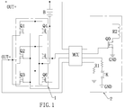
- FIG. 1 shows a circuit diagram of the present invention.
- the present invention discloses a car starter which is able to work under very low temperature and a protection circuit thereof, comprising primarily a positive electrode output end OUT+, a negative electrode output end OUT-, an MCU single-chip microcomputer, a starter B, a power heating circuit 2 which controls the heating status of the power, and a MOS tube control circuit 1 which enters into a closed state when an external level is lowered.
- the positive electrode of the starter B is connected respectively with the positive electrode output end OUT+ and the power heating circuit 2, an end of the MOS tube control circuit 1 is connected with the negative electrode output end OUT-, and the other end of the MOS tube control circuit 1 is connected with the negative electrode of the starter B.
- Two pins are drawn from the MCU single-chip microcomputer to connect respectively with the positive electrode output end OUT+ and the negative electrode output end OUT-. Another two pins are also drawn from the MCU single-chip microcomputer to connect respectively with one of two ends of the MOS tube control circuit 1. In addition, another three pins are drawn from the MCU single-chip microcomputer to connect with the power heating circuit 2.
- the car starter which is able to work under very low temperature and the protection circuit thereof, according to the present invention are provided with an independent power heating circuit 2 to heat up the batteries of a car starter quickly and safely in a low temperature environment, so that the batteries of the car starter can achieve a reasonable working temperature, thereby solving the problems of using the car starter under low temperature.
- the MCU single-chip microcomputer when the circuit is short-circuited, the MCU single-chip microcomputer will receive a voltage which exceeds a predetermined value; whereas, the pins of the MCU single-chip microcomputer and the MOS tube control circuit 1 will be lowered quickly to become a low level, and the MOS tube control circuit 1 will enter into a closed state to protect the electronic parts between the positive electrode output end OUT+ and the negative electrode output end OUT-.
- the MCU single-chip microcomputer controls the on or off of the MOS tubes, by detecting whether the electric current flowing through the MOS tubes is abnormal and whether the temperature of the MOS tubes is abnormal, to implement protection.
- the advantage of this kind of circuit is that the circuit will turn off the outputs immediately when short-circuiting, which protects the circuits on the starter and the clamps, thereby solving the safety issues of the starter effectively.
- the power heating circuit 2 includes a press button K by which an instruction is sent out to the MCU single-chip microcomputer to heat up the power or not, a thermistor R1 which senses the environment temperature, an amplifying MOS tube Q0 and a thermal fuse R2 which provides heat to the power.
- the MCU single-chip microcomputer is connected electrically with the press button K, the thermistor R1 and the grid of the amplifying MOS tube Q0, respectively.
- An end of the thermal fuse R2 is connected electrically with the drain of the amplifying MOS tube Q0, and the other end of the thermal fuse R2 is connected electrically with the starter B.
- the press button K When the temperature of the starter B is low, the press button K is pressed down to control the thermal fuse R2 to heat up, thereby increasing the temperature of the power in time.
- an external heating method is used, wherein an independent low-temperature press button is added without affecting the usage of the existing car starter B.
- the low-temperature press button controls an independent circuit to heat up the batteries of the car starter B quickly and safely in a low temperature environment.
- An end of the press button K is connected electrically with the MCU single-chip microcomputer, and the other end of the press button K is grounded to release statics.
- An end of the thermistor R1 is connected electrically with the MCU single-chip microcomputer, and the other end of the thermistor R1 is grounded to release statics.
- the source of the amplifying MOS tube Q0 is grounded.
- the MOS tube control circuit 1 includes a first MOS tube Q1, a second MOS tube Q2, a third MOS tube Q3, a fourth MOS tube Q4, a fifth MOS tube Q5 and a sixth MOS tube Q6, wherein the sources of the first MOS tube Q1, second MOS tube Q2 and third MOS tube Q3 are connected respectively with the negative electrode output end OUT-, and the grids are connected respectively with the MCU single-chip microcomputer.
- the sources of the fourth MOS tube Q4, fifth MOS tube Q5 and sixth MOS tube Q6 are connected respectively with the power, and the grids are connected respectively with the MCU single-chip microcomputer.
- the drains of the first MOS tube Q1, second MOS tube Q2 and third MOS tube Q3 are connected with one another, and the drains of the fourth MOS tube Q4, fifth MOS tube Q5 and sixth MOS tube Q6 are connected with one another.
- the first MOS tube Q1, second MOS tube Q2, third MOS tube Q3, fourth MOS tube Q4, fifth MOS tube Q5 and sixth MOS tube Q6 are all an N-shaped MOS tube.
Abstract
Description
- The present invention relates to a technical field in starting up a car under very low temperature and in securing safe driving, and more particularly to a car starter which is able to work under very low temperature and a protection circuit thereof.
- As the continuous development in automobile industries, most of the existing cars are operated on automatic shifts. Therefore, when the car batteries do not work, the driver will have to call for rescue. However, this process will require a long time of waiting and sometimes the driver will need to pay expensive fees. To solve these issues, many mobile power bank companies have brought up a car starter to ignite the car, accordingly. As being able to be carried very conveniently, along with the function of recharging a cell phone, a laptop computer or a camera, this power source is very popular immediately upon being shown up in the markets.
- It is well known that there are in general two reasons why a car cannot be started:
- 1. The car batteries are depleted.
- 2. The car batteries are charged but the temperature of the batteries is too low to work.
- For the first problem, people will replace the batteries periodically. However, for the second problem, there is currently no good approach to deal with it.
- Accordingly, the present invention discloses a proper means to solve these two problems. An existing car starter uses generally high-rate lithium polymer batteries and the effective working temperature of these batteries is between -10°C and 60°C. It means that the car starter will not work when the temperature is below -10°C (through an effective treatment, some vendors can bring up the batteries that can work at -20°C). However, in practical use, the condition that the temperature is below -10°C will happen very often. Therefore, to solve this problem, many vendors focus on solving the technical difficulty in the working temperature of the high-rate lithium polymer batteries. Due to the limitation of the properties of the batteries themselves, this technical breakthrough is very difficult.
- The present invention applies a high stability heating technique to build up a suitable working environment for the batteries, thereby effectively solving the difficulty in that the batteries cannot work at a very low temperature of -40°C. On the other hand, as a very high electric current of more than or equal to 200A is required to start the car, a lot of side effects will be resulted from this high electric current, such as the burn-down of electronic parts when starting the car repeatedly, which will damage the ignition clamps. The less severe outcome is that the car cannot be started and the more severe outcome is that the mobile power bank will be recharged back from the car batteries, causing fire or swelling to the mobile power bank. To solve this problem, many vendors change the number of primary electronic parts of the ignition clamps from 2 to 4 or 6. Other vendors add fuses to increase the safety based on the original design. Nevertheless, all these means are not able to solve the issues in safe use of the car starter completely.
- The present invention relates to a technical field in starting up a car under very low temperature and in securing safe driving, and more particularly to a car starter which is able to work under very low temperature and a protection circuit thereof, which are very practical.
- To achieve the abovementioned object, the present invention discloses a car starter which is able to work under very low temperature and a protection circuit thereof, including primarily an MCU (Microcontroller Unit) single-chip microcomputer, a starter, a power heating circuit which controls the heating status of the power, a positive electrode output end, a negative electrode output end, and a MOS (Metal-Oxide Semiconductor) tube control circuit which enters into a closed state when an external level is lowered. The positive electrode of the said starter is connected respectively with the positive electrode output end and the power heating circuit, an end of the said MOS tube control circuit is connected with the negative electrode output end, and the other end of the said MOS tube control circuit is connected with the negative electrode of the starter. Two pins are drawn from the said MCU single-chip microcomputer to connect respectively with the positive electrode output end and the negative electrode output end. Another two pins are also drawn from the said MCU single-chip microcomputer to connect respectively with one of two ends of the MOS tube control circuit. In addition, another three pins are drawn from the said MCU single-chip microcomputer to connect with the power heating circuit.
- The said power heating circuit includes a press button by which an instruction is sent out to the MCU single-chip microcomputer to heat up the power or not, a thermistor which senses the environment temperature, an amplifying MOS tube and a thermal fuse which provides heat to the power. The said MCU single-chip microcomputer is connected electrically with the press button, the thermistor and the grid of the amplifying MOS tube, respectively. An end of the said thermal fuse is connected electrically with the drain of the amplifying MOS tube, and the other end of the said thermal fuse is connected electrically with the starter.
- An end of the said press button is connected electrically with the MCU single-chip microcomputer, and the other end of the said press button is grounded to release statics. An end of the said thermistor is connected electrically with the MCU single-chip microcomputer, and the other end of the said thermistor is grounded to release statics. The source of the said amplifying MOS tube is grounded.
- The said MOS tube control circuit includes a first MOS tube, a second MOS tube, a third MOS tube, a fourth MOS tube, a fifth MOS tube and a sixth MOS tube. The sources of the said first MOS tube, second MOS tube and third MOS tube are connected respectively with the negative electrode output end, and the grids are connected respectively with the MCU single-chip microcomputer. The sources of the said fourth MOS tube, fifth MOS tube and sixth MOS tube are connected respectively with the power, and the grids are connected respectively with the MCU single-chip microcomputer. The drains of the said first MOS tube, second MOS tube and third MOS tube are connected with one another, and the drains of the said fourth MOS tube, fifth MOS tube and sixth MOS tube are connected with one another.
- The said first MOS tube, second MOS tube, third MOS tube, fourth MOS tube, fifth MOS tube and sixth MOS tube are all an N-shaped MOS tube.
- The benefits of the present invention are disclosed below.
- In comparison with the existing technology, the car starter which is able to work under very low temperature and the protection circuit thereof, according to the present invention, are provided with an independent power heating circuit to heat up the batteries of a car starter quickly and safely in a low temperature environment, so that the batteries of the car starter can achieve a reasonable working temperature, thereby solving the problems of using the car starter under low temperature. In addition, when the circuit is short-circuited, the MCU single-chip microcomputer will receive a voltage which exceeds a predetermined value; whereas, the pins of the MCU single-chip microcomputer and the MOS tube control circuit will be lowered quickly to become a low level, and the MOS tube control circuit will enter into a closed state to protect the electronic parts between the positive electrode output end and the negative electrode output end. In the present invention, the MCU single-chip microcomputer controls the on or off of the MOS tubes, by detecting whether the electric current flowing through the MOS tubes is abnormal and whether the temperature of the MOS tubes is abnormal, to implement protection. The advantage of this kind of circuit is that the circuit will turn off the outputs immediately when short-circuiting, which protects the circuits on the starter and the clamps, thereby solving the safety issues of the starter effectively.
- To enable a further understanding of the said objectives and the technological methods of the invention herein, the brief description of the drawings below is followed by the detailed description of the preferred embodiments.
-
FIG. 1 shows a circuit diagram of the present invention. - Referring to
FIG. 1 , the present invention discloses a car starter which is able to work under very low temperature and a protection circuit thereof, comprising primarily a positive electrode output end OUT+, a negative electrode output end OUT-, an MCU single-chip microcomputer, a starter B, a power heating circuit 2 which controls the heating status of the power, and a MOS tube control circuit 1 which enters into a closed state when an external level is lowered. The positive electrode of the starter B is connected respectively with the positive electrode output end OUT+ and the power heating circuit 2, an end of the MOS tube control circuit 1 is connected with the negative electrode output end OUT-, and the other end of the MOS tube control circuit 1 is connected with the negative electrode of the starter B. Two pins are drawn from the MCU single-chip microcomputer to connect respectively with the positive electrode output end OUT+ and the negative electrode output end OUT-. Another two pins are also drawn from the MCU single-chip microcomputer to connect respectively with one of two ends of the MOS tube control circuit 1. In addition, another three pins are drawn from the MCU single-chip microcomputer to connect with the power heating circuit 2. - In comparison with the existing technology, the car starter which is able to work under very low temperature and the protection circuit thereof, according to the present invention, are provided with an independent power heating circuit 2 to heat up the batteries of a car starter quickly and safely in a low temperature environment, so that the batteries of the car starter can achieve a reasonable working temperature, thereby solving the problems of using the car starter under low temperature. In addition, when the circuit is short-circuited, the MCU single-chip microcomputer will receive a voltage which exceeds a predetermined value; whereas, the pins of the MCU single-chip microcomputer and the MOS tube control circuit 1 will be lowered quickly to become a low level, and the MOS tube control circuit 1 will enter into a closed state to protect the electronic parts between the positive electrode output end OUT+ and the negative electrode output end OUT-. In the present invention, the MCU single-chip microcomputer controls the on or off of the MOS tubes, by detecting whether the electric current flowing through the MOS tubes is abnormal and whether the temperature of the MOS tubes is abnormal, to implement protection. The advantage of this kind of circuit is that the circuit will turn off the outputs immediately when short-circuiting, which protects the circuits on the starter and the clamps, thereby solving the safety issues of the starter effectively.
- The power heating circuit 2 includes a press button K by which an instruction is sent out to the MCU single-chip microcomputer to heat up the power or not, a thermistor R1 which senses the environment temperature, an amplifying MOS tube Q0 and a thermal fuse R2 which provides heat to the power. The MCU single-chip microcomputer is connected electrically with the press button K, the thermistor R1 and the grid of the amplifying MOS tube Q0, respectively. An end of the thermal fuse R2 is connected electrically with the drain of the amplifying MOS tube Q0, and the other end of the thermal fuse R2 is connected electrically with the starter B. When the temperature of the starter B is low, the press button K is pressed down to control the thermal fuse R2 to heat up, thereby increasing the temperature of the power in time. In the present invention, an external heating method is used, wherein an independent low-temperature press button is added without affecting the usage of the existing car starter B. The low-temperature press button controls an independent circuit to heat up the batteries of the car starter B quickly and safely in a low temperature environment.
- An end of the press button K is connected electrically with the MCU single-chip microcomputer, and the other end of the press button K is grounded to release statics. An end of the thermistor R1 is connected electrically with the MCU single-chip microcomputer, and the other end of the thermistor R1 is grounded to release statics. The source of the amplifying MOS tube Q0 is grounded.
- The MOS tube control circuit 1 includes a first MOS tube Q1, a second MOS tube Q2, a third MOS tube Q3, a fourth MOS tube Q4, a fifth MOS tube Q5 and a sixth MOS tube Q6, wherein the sources of the first MOS tube Q1, second MOS tube Q2 and third MOS tube Q3 are connected respectively with the negative electrode output end OUT-, and the grids are connected respectively with the MCU single-chip microcomputer. The sources of the fourth MOS tube Q4, fifth MOS tube Q5 and sixth MOS tube Q6 are connected respectively with the power, and the grids are connected respectively with the MCU single-chip microcomputer. The drains of the first MOS tube Q1, second MOS tube Q2 and third MOS tube Q3 are connected with one another, and the drains of the fourth MOS tube Q4, fifth MOS tube Q5 and sixth MOS tube Q6 are connected with one another.
- The first MOS tube Q1, second MOS tube Q2, third MOS tube Q3, fourth MOS tube Q4, fifth MOS tube Q5 and sixth MOS tube Q6 are all an N-shaped MOS tube.
- It is of course to be understood that the embodiments described herein is merely illustrative of the principles of the invention and that a wide variety of modifications thereto may be effected by persons skilled in the art without departing from the spirit and scope of the invention as set forth in the following claims.
Claims (5)
- A car starter which works under very low temperature and a protection circuit thereof, wherein having a circuit which starts the car safely under a reasonably very low temperature condition and having a protection circuit, comprising an MCU (Microcontroller Unit) single-chip microcomputer, a starter B, a power heating circuit 2 which controls the heating status of the power, a positive electrode output end OUT+, a negative electrode output end OUT- and a MOS (Metal-Oxide Semiconductor) tube control circuit 1 which enters into a closed state when an external level is lowered, wherein the positive electrode of the starter B is connected respectively with the positive electrode output end OUT+ and the power heating circuit 2, an end of the MOS tube control circuit 1 is connected with the negative electrode output end OUT-, the other end of the MOS tube control circuit 1 is connected with the negative electrode of the starter B, two pins are drawn from the MCU single-chip microcomputer to connect respectively with the positive electrode output end OUT+ and the negative electrode output end OUT-, another two pins are drawn from the MCU single-chip microcomputer to connect respectively with one of two ends of the MOS tube control circuit 1, and another three pins are drawn from the MCU single-chip microcomputer to connect with the power heating circuit 2.
- The car starter which works under very low temperature and the protection circuit thereof, according to claim 1, wherein the power heating circuit 2 includes a press button K which sends out an instruction to the MCU single-chip microcomputer to heat up the power or not, a thermistor R1 which senses the environment temperature, an amplifying MOS tube Q0 and a thermal fuse R2 which provides heat to the power; the MCU single-chip microcomputer being connected electrically with the press button K, the thermistor R1, and grid of the amplifying MOS tube Q0, respectively; an end of the thermistor R1 being connected electrically with drain of the amplifying MOS tube Q0, and the other end of the thermistor R1 being connected electrically with the starter B.
- The car starter which works under very low temperature and the protection circuit thereof, according to claim 2, wherein an end of the press button K is connected electrically with the MCU single-chip microcomputer, the other end of the press button K is grounded to release statics, an end of the thermistor R1 is connected electrically with the MCU single-chip microcomputer, the other end of the thermistor R1 is grounded to release statics, and source of the amplifying MOS tube Q0 is grounded.
- The car starter which works under very low temperature and the protection circuit thereof, according to claim 1, wherein the MOS tube control circuit 1 includes a first MOS tube Q1, a second MOS tube Q2, a third MOS tube Q3, a fourth MOS tube Q4, a fifth MOS tube Q5 and a sixth MOS tube Q6, with sources of the first MOS tube Q1, second MOS tube Q2 and third MOS tube Q3 being connected respectively with the negative electrode output end OUT-, and grids being connected respectively with the MCU single-chip microcomputer; sources of the fourth MOS tube Q4, fifth MOS tube Q5 and sixth MOS tube Q6 being connected respectively with the power, and grids being connected respectively with the MCU single-chip microcomputer; drains of the first MOS tube Q1, second MOS tube Q2 and third MOS tube Q3 being connected with one another, and drains of the fourth MOS tube Q4, fifth MOS tube Q5 and sixth MOS tube Q6 being connected with one another.
- The car starter which works under very low temperature and the protection circuit thereof, according to claim 4, wherein the first MOS tube Q1, second MOS tube Q2, third MOS tube Q3, fourth MOS tube Q4, fifth MOS tube Q5 and sixth MOS tube Q6 are all an N-shaped MOS tube.
Applications Claiming Priority (2)
| Application Number | Priority Date | Filing Date | Title |
|---|---|---|---|
| CN201520274043.9U CN204741260U (en) | 2015-04-30 | 2015-04-30 | Vehicle starting power's safety protection circuit |
| CN201520274107.5U CN204761733U (en) | 2015-04-30 | 2015-04-30 | Vehicle starting power that low temperature can be worked down |
Publications (2)
| Publication Number | Publication Date |
|---|---|
| EP3112665A2 true EP3112665A2 (en) | 2017-01-04 |
| EP3112665A3 EP3112665A3 (en) | 2017-03-15 |
Family
ID=56087088
Family Applications (1)
| Application Number | Title | Priority Date | Filing Date |
|---|---|---|---|
| EP16167578.0A Withdrawn EP3112665A3 (en) | 2015-04-30 | 2016-04-28 | Car starter which works under very low temperature and a protection circuit thereof |
Country Status (6)
| Country | Link |
|---|---|
| US (1) | US20160318405A1 (en) |
| EP (1) | EP3112665A3 (en) |
| JP (1) | JP3205187U (en) |
| CA (1) | CA2927892A1 (en) |
| DE (1) | DE202016102285U1 (en) |
| TW (1) | TWM532111U (en) |
Families Citing this family (2)
| Publication number | Priority date | Publication date | Assignee | Title |
|---|---|---|---|---|
| JP7024463B2 (en) * | 2018-02-01 | 2022-02-24 | 株式会社Gsユアサ | Management device, power storage device, management method of power storage element |
| CN109958566A (en) * | 2019-04-20 | 2019-07-02 | 济南吉美乐电源技术有限公司 | A kind of engine starting gear based on metal-oxide-semiconductor control |
Family Cites Families (7)
| Publication number | Priority date | Publication date | Assignee | Title |
|---|---|---|---|---|
| US6002240A (en) * | 1997-12-12 | 1999-12-14 | Dell Usa, L.P. | Self heating of batteries at low temperatures |
| EP2647102A4 (en) * | 2010-11-29 | 2016-11-02 | Martin Koebler | Lithium starter battery and solid state switch therefor |
| US9954207B2 (en) * | 2010-11-29 | 2018-04-24 | Martin Koebler | Lithium battery with solid state switch |
| CN103419666B (en) * | 2012-05-22 | 2016-03-02 | 比亚迪股份有限公司 | The power system of electronlmobil, electronlmobil and heating of battery method |
| CN203660017U (en) * | 2013-11-28 | 2014-06-18 | 东莞市云帆电子科技有限公司 | Preheating system of automobile emergency start power source |
| US9726135B2 (en) * | 2014-02-21 | 2017-08-08 | Briggs & Stratton Corporation | Snowthrower with removable self-heating starter battery pack |
| CN104377402B (en) * | 2014-12-02 | 2017-01-11 | 天津航空机电有限公司 | Control and fault diagnosing system of battery heater |
-
2016
- 2016-04-21 TW TW105205611U patent/TWM532111U/en not_active IP Right Cessation
- 2016-04-22 CA CA2927892A patent/CA2927892A1/en not_active Abandoned
- 2016-04-26 US US15/138,750 patent/US20160318405A1/en not_active Abandoned
- 2016-04-27 JP JP2016001946U patent/JP3205187U/en not_active Expired - Fee Related
- 2016-04-28 EP EP16167578.0A patent/EP3112665A3/en not_active Withdrawn
- 2016-04-28 DE DE202016102285.1U patent/DE202016102285U1/en not_active Expired - Lifetime
Non-Patent Citations (1)
| Title |
|---|
| None |
Also Published As
| Publication number | Publication date |
|---|---|
| CA2927892A1 (en) | 2016-10-30 |
| US20160318405A1 (en) | 2016-11-03 |
| EP3112665A3 (en) | 2017-03-15 |
| DE202016102285U1 (en) | 2016-06-02 |
| JP3205187U (en) | 2016-07-07 |
| TWM532111U (en) | 2016-11-11 |
Similar Documents
| Publication | Publication Date | Title |
|---|---|---|
| JP6833984B2 (en) | Battery, terminal, and charging system | |
| JP6198258B2 (en) | Power supply terminal, and charging control method and apparatus | |
| JP5547342B2 (en) | Advanced storage battery system | |
| CN101171704B (en) | Protection circuit for secondary battery and secondary battery comprising the same | |
| TWI751229B (en) | Control device, control system, power storage device, and computer readable media | |
| WO2009110221A1 (en) | Charge method and charge device | |
| US20110285359A1 (en) | Charging Method And Charging Device For Charging A Rechargeable Battery | |
| CN103986040A (en) | Automatic power-off type USB charging connecting wire and application thereof | |
| TW201417452A (en) | Portable charger capable of providing alternating current | |
| WO2013108336A1 (en) | Secondary battery protection circuit, battery pack, and electronic apparatus | |
| EP3112665A2 (en) | Car starter which works under very low temperature and a protection circuit thereof | |
| CN105471018A (en) | Charging/discharging control device and battery device | |
| EP3059831A1 (en) | Secondary lithium battery for vehicle use | |
| CN103972756A (en) | USB (Universal Serial Bus) charging connecting wire capable of performing countdown power failure | |
| JP6110235B2 (en) | Power storage device | |
| TW201027871A (en) | Apparatus and method for protecting battery by comparison of full charge capacity | |
| CN105162078B (en) | The charge protector and method and terminal of a kind of terminal | |
| CN204741260U (en) | Vehicle starting power's safety protection circuit | |
| JP2012200113A (en) | Battery pack and charging system | |
| CN207010214U (en) | A kind of multiple current foldback circuit of battery | |
| CN202940367U (en) | Safety charging socket for electric bicycle | |
| TWI463721B (en) | Battery management system with multiple mode and switching method thereof | |
| WO2010115355A1 (en) | Data card and method for supplying power by data card | |
| TWI819873B (en) | Energy storage device as well as method, computer program, and computer readable medium for intermittently discharging inverter of said energy storage device | |
| KR101671906B1 (en) | apparatus for controlling battery and method thereof |
Legal Events
| Date | Code | Title | Description |
|---|---|---|---|
| PUAI | Public reference made under article 153(3) epc to a published international application that has entered the european phase |
Free format text: ORIGINAL CODE: 0009012 |
|
| 17P | Request for examination filed |
Effective date: 20160609 |
|
| AK | Designated contracting states |
Kind code of ref document: A2 Designated state(s): AL AT BE BG CH CY CZ DE DK EE ES FI FR GB GR HR HU IE IS IT LI LT LU LV MC MK MT NL NO PL PT RO RS SE SI SK SM TR |
|
| AX | Request for extension of the european patent |
Extension state: BA ME |
|
| PUAL | Search report despatched |
Free format text: ORIGINAL CODE: 0009013 |
|
| AK | Designated contracting states |
Kind code of ref document: A3 Designated state(s): AL AT BE BG CH CY CZ DE DK EE ES FI FR GB GR HR HU IE IS IT LI LT LU LV MC MK MT NL NO PL PT RO RS SE SI SK SM TR |
|
| AX | Request for extension of the european patent |
Extension state: BA ME |
|
| RIC1 | Information provided on ipc code assigned before grant |
Ipc: F02N 11/10 20060101AFI20170206BHEP Ipc: F02N 11/12 20060101ALI20170206BHEP |
|
| STAA | Information on the status of an ep patent application or granted ep patent |
Free format text: STATUS: THE APPLICATION IS DEEMED TO BE WITHDRAWN |
|
| 18D | Application deemed to be withdrawn |
Effective date: 20170916 |