EP3112652A2 - Egr control method and egr device - Google Patents
Egr control method and egr device Download PDFInfo
- Publication number
- EP3112652A2 EP3112652A2 EP16168972.4A EP16168972A EP3112652A2 EP 3112652 A2 EP3112652 A2 EP 3112652A2 EP 16168972 A EP16168972 A EP 16168972A EP 3112652 A2 EP3112652 A2 EP 3112652A2
- Authority
- EP
- European Patent Office
- Prior art keywords
- egr
- exhaust gas
- egr valve
- flow rate
- distribution property
- Prior art date
- Legal status (The legal status is an assumption and is not a legal conclusion. Google has not performed a legal analysis and makes no representation as to the accuracy of the status listed.)
- Granted
Links
Images


Classifications
-
- F—MECHANICAL ENGINEERING; LIGHTING; HEATING; WEAPONS; BLASTING
- F02—COMBUSTION ENGINES; HOT-GAS OR COMBUSTION-PRODUCT ENGINE PLANTS
- F02M—SUPPLYING COMBUSTION ENGINES IN GENERAL WITH COMBUSTIBLE MIXTURES OR CONSTITUENTS THEREOF
- F02M26/00—Engine-pertinent apparatus for adding exhaust gases to combustion-air, main fuel or fuel-air mixture, e.g. by exhaust gas recirculation [EGR] systems
- F02M26/49—Detecting, diagnosing or indicating an abnormal function of the EGR system
-
- F—MECHANICAL ENGINEERING; LIGHTING; HEATING; WEAPONS; BLASTING
- F02—COMBUSTION ENGINES; HOT-GAS OR COMBUSTION-PRODUCT ENGINE PLANTS
- F02D—CONTROLLING COMBUSTION ENGINES
- F02D41/00—Electrical control of supply of combustible mixture or its constituents
- F02D41/0025—Controlling engines characterised by use of non-liquid fuels, pluralities of fuels, or non-fuel substances added to the combustible mixtures
- F02D41/0047—Controlling exhaust gas recirculation [EGR]
- F02D41/0065—Specific aspects of external EGR control
- F02D41/0072—Estimating, calculating or determining the EGR rate, amount or flow
-
- F—MECHANICAL ENGINEERING; LIGHTING; HEATING; WEAPONS; BLASTING
- F02—COMBUSTION ENGINES; HOT-GAS OR COMBUSTION-PRODUCT ENGINE PLANTS
- F02D—CONTROLLING COMBUSTION ENGINES
- F02D41/00—Electrical control of supply of combustible mixture or its constituents
- F02D41/0025—Controlling engines characterised by use of non-liquid fuels, pluralities of fuels, or non-fuel substances added to the combustible mixtures
- F02D41/0047—Controlling exhaust gas recirculation [EGR]
- F02D41/0077—Control of the EGR valve or actuator, e.g. duty cycle, closed loop control of position
-
- F—MECHANICAL ENGINEERING; LIGHTING; HEATING; WEAPONS; BLASTING
- F02—COMBUSTION ENGINES; HOT-GAS OR COMBUSTION-PRODUCT ENGINE PLANTS
- F02D—CONTROLLING COMBUSTION ENGINES
- F02D41/00—Electrical control of supply of combustible mixture or its constituents
- F02D41/24—Electrical control of supply of combustible mixture or its constituents characterised by the use of digital means
- F02D41/2406—Electrical control of supply of combustible mixture or its constituents characterised by the use of digital means using essentially read only memories
- F02D41/2425—Particular ways of programming the data
- F02D41/2429—Methods of calibrating or learning
- F02D41/2451—Methods of calibrating or learning characterised by what is learned or calibrated
- F02D41/2464—Characteristics of actuators
-
- F—MECHANICAL ENGINEERING; LIGHTING; HEATING; WEAPONS; BLASTING
- F02—COMBUSTION ENGINES; HOT-GAS OR COMBUSTION-PRODUCT ENGINE PLANTS
- F02M—SUPPLYING COMBUSTION ENGINES IN GENERAL WITH COMBUSTIBLE MIXTURES OR CONSTITUENTS THEREOF
- F02M26/00—Engine-pertinent apparatus for adding exhaust gases to combustion-air, main fuel or fuel-air mixture, e.g. by exhaust gas recirculation [EGR] systems
- F02M26/02—EGR systems specially adapted for supercharged engines
- F02M26/04—EGR systems specially adapted for supercharged engines with a single turbocharger
- F02M26/05—High pressure loops, i.e. wherein recirculated exhaust gas is taken out from the exhaust system upstream of the turbine and reintroduced into the intake system downstream of the compressor
-
- F—MECHANICAL ENGINEERING; LIGHTING; HEATING; WEAPONS; BLASTING
- F02—COMBUSTION ENGINES; HOT-GAS OR COMBUSTION-PRODUCT ENGINE PLANTS
- F02M—SUPPLYING COMBUSTION ENGINES IN GENERAL WITH COMBUSTIBLE MIXTURES OR CONSTITUENTS THEREOF
- F02M26/00—Engine-pertinent apparatus for adding exhaust gases to combustion-air, main fuel or fuel-air mixture, e.g. by exhaust gas recirculation [EGR] systems
- F02M26/13—Arrangement or layout of EGR passages, e.g. in relation to specific engine parts or for incorporation of accessories
- F02M26/22—Arrangement or layout of EGR passages, e.g. in relation to specific engine parts or for incorporation of accessories with coolers in the recirculation passage
- F02M26/23—Layout, e.g. schematics
- F02M26/25—Layout, e.g. schematics with coolers having bypasses
-
- F—MECHANICAL ENGINEERING; LIGHTING; HEATING; WEAPONS; BLASTING
- F02—COMBUSTION ENGINES; HOT-GAS OR COMBUSTION-PRODUCT ENGINE PLANTS
- F02M—SUPPLYING COMBUSTION ENGINES IN GENERAL WITH COMBUSTIBLE MIXTURES OR CONSTITUENTS THEREOF
- F02M26/00—Engine-pertinent apparatus for adding exhaust gases to combustion-air, main fuel or fuel-air mixture, e.g. by exhaust gas recirculation [EGR] systems
- F02M26/45—Sensors specially adapted for EGR systems
- F02M26/46—Sensors specially adapted for EGR systems for determining the characteristics of gases, e.g. composition
- F02M26/47—Sensors specially adapted for EGR systems for determining the characteristics of gases, e.g. composition the characteristics being temperatures, pressures or flow rates
-
- Y—GENERAL TAGGING OF NEW TECHNOLOGICAL DEVELOPMENTS; GENERAL TAGGING OF CROSS-SECTIONAL TECHNOLOGIES SPANNING OVER SEVERAL SECTIONS OF THE IPC; TECHNICAL SUBJECTS COVERED BY FORMER USPC CROSS-REFERENCE ART COLLECTIONS [XRACs] AND DIGESTS
- Y02—TECHNOLOGIES OR APPLICATIONS FOR MITIGATION OR ADAPTATION AGAINST CLIMATE CHANGE
- Y02T—CLIMATE CHANGE MITIGATION TECHNOLOGIES RELATED TO TRANSPORTATION
- Y02T10/00—Road transport of goods or passengers
- Y02T10/10—Internal combustion engine [ICE] based vehicles
- Y02T10/40—Engine management systems
Definitions
- the invention relates to operation control of an exhaust gas recirculation device for an internal combustion engine and, in particular, to operation control for suppressing and preventing degradation of operation efficiency due to secular change and for improving reliability of an operation of the device.
- an exhaust gas recirculation device (an EGR device) is used to improve an emission property and the like in an internal combustion engine, and various suggestions and implementation of a configuration, operation control, and the like thereof have conventionally been made (see PTL 1, for example).
- exhaust gas is circulated to an intake side via a communication passageway for communicating between an intake pipe and an exhaust pipe, and a circulation amount is usually adjusted by adjusting an opening degree of an EGR valve that is provided in the communication passageway.
- the exhaust gas to be circulated contains soot and the like.
- the soot and the like are gradually adhered to an inner wall of the EGR valve, which results in a reduction in an effective opening area thereof and also results in degradation of operation efficiency of the entire device. Accordingly, it may not be possible to guarantee sufficient performance of the device.
- a method for compensating for a change in a flow rate of circulated exhaust gas, which is caused by the gradual reduction in the effective opening area of the EGR valve, by executing flow rate control based on an I term (an integral term) component of PID control is considered.
- the former flow rate control that is based on the I term (the integral term) of the PID control has such a disadvantage that transient responsiveness is degraded as a degree of contribution of the I term component in the flow rate control is increased. Accordingly, flow rate control in which both of the responsiveness and the contribution are compromised has to be adopted in reality. Thus, such a problem arises that satisfying control cannot always be realized.
- the invention has been made in view of the above circumstances and therefore provides an EGR control method and an EGR device capable of reliably detecting a reduction in a flow rate of circulated exhaust gas that is associated with secular change and capable of compensating for the reduction in the flow rate.
- an EGR control method is an EGR control method in an EGR device that is configured to be able to circulate some of exhaust gas of an internal combustion engine to an intake side of the internal combustion engine, and is configured to correct a circulation amount of the exhaust gas to the intake side by an EGR valve for controlling the circulation amount of the exhaust gas in accordance with a degree of degradation of a distribution property of the exhaust gas in the EGR valve when the distribution property falls below a specified standard.
- an EGR device configured to be provided with an EGR valve that is configured to be able to control a valve position in a communication passageway for communicating between an exhaust pipe and an intake pipe of an internal combustion engine and to change a communication state of the communication passageway by operation control of the EGR valve by an electronic control unit, so as to be able to circulate some of exhaust gas to an intake side, in which the electronic control unit is configured to correct a circulation amount of the exhaust gas by the EGR valve in accordance with a degree of degradation of a distribution property of the exhaust gas in the EGR valve when it is determined that the distribution property falls below a specified standard.
- the reduction in the flow rate in the EGR valve is detected on the basis of whether the distribution property of the circulated exhaust gas in the EGR valve is equal to a below the standard, and the flow rate of the circulated exhaust gas is corrected in accordance with the degree of the degradation of the distribution property.
- the reduction in the flow rate in the EGR valve in other words, occurrence of clogging caused by soot and the like can reliably be comprehended, and suitable compensation for the reduction in the flow rate can be made. Therefore, an effect of being able to improve stability and reliability of an operation of the device is exerted.
- the fuel injection controller of the common rail type in the embodiment of the invention is configured by including as main components: a high-pressure pump device 50 that pressure-feeds high pressure fuel; a common rail 1 that stores the high pressure fuel pressure-fed from this high-pressure pump device 50; plural fuel injection valves 2-1 to 2-n that inject and supply the high pressure fuel supplied from this common rail 1 to cylinders of a diesel engine (hereinafter referred to as an "engine") 3 as the internal combustion engine; and an electronic control unit (indicated as "ECU” in Fig. 1 ) 4 that executes fuel injection control processing, EGR control processing for the internal combustion engine, which will be described below, and the like.
- a high-pressure pump device 50 that pressure-feeds high pressure fuel
- a common rail 1 that stores the high pressure fuel pressure-fed from this high-pressure pump device 50
- plural fuel injection valves 2-1 to 2-n that inject and supply the high pressure fuel supplied from this common rail 1 to cylinders of a diesel engine (hereinafter referred to as an "engine")
- Such a configuration itself is the same as a basic configuration of the fuel injection controller of the common rail type of this type that has conventionally and widely been known.
- the high-pressure pump device 50 has a known or well-known configuration that includes a supply pump 5, a metering valve 6, and a high-pressure pump 7 as main components.
- a return valve 8 is provided between an output side of the supply pump 5 and the fuel tank 9, so as to be able to return a surplus of the fuel on the output side of the supply pump 5 to the fuel tank 9.
- the supply pump 5 may be provided as a separate component from the high-pressure pump device 50 on an upstream side of the high-pressure pump device 50, or may be provided in the fuel tank 9.
- the fuel injection valves 2-1 to 2-n are respectively provided for the cylinders of the engine 3, are each supplied with the high pressure fuel from the common rail 1, and each inject the fuel through injection control by the electronic control unit 4.
- the electronic control unit 4 is, for example, centered on a microcomputer (not depicted) that has a known or well-known configuration, has memory elements (not depicted) such as a RAM and a ROM, and is configured by including: a circuit (not depicted) for energizing and driving the fuel injection valves 2-1 to 2-n; and a circuit (not depicted) for energizing and driving the metering valve 6 and the like, as main components.
- Such an electronic control unit 4 receives a detection signal of a pressure sensor 11 that detects pressure of the common rail 1, and also receives various detection signals, such as an engine speed, an accelerator pedal position, an ambient temperature, and atmospheric pressure, so as to use these signals for operation control and fuel injection control of the engine 3 and further for EGR control processing and the like in the embodiment of the invention.
- Fig. 2 depicts a configuration example of an exhaust gas recirculation device 101 that is provided for emission reduction of the engine 3 and the like, and a configuration thereof and the like will hereinafter be described with reference to the same drawing.
- an intake pipe 12 for taking air that is required to combust the fuel and an exhaust pipe 13 for discharging exhaust gas are respectively connected to an intake manifold 14a and an exhaust manifold 14b of the engine 3.
- a communication passageway 15 for communicating between the exhaust pipe 13 and the intake pipe 12 are provided at appropriate positions of the exhaust pipe 13 and the intake pipe 12, and an EGR cooler 17 for cooling passing exhaust gas and an EGR valve 16 for adjusting a communication state of the communication passageway 15, in other words, a circulation amount of the exhaust gas are sequentially disposed from the exhaust pipe 13 side in the middle of this communication passageway 15.
- variable turbocharger 18 that includes: a variable turbine 19 provided on a downstream side of the communication passageway 15 in the exhaust pipe 13; and a compressor 20 provided on an upstream side of the communication passageway 15 in the intake pipe 12, as main components, and that has a known or well-known configuration is provided.
- the compressor 20 rotates by rotary power that is obtained from the variable turbine 19, and compressed air is delivered as intake air to the intake manifold 14a.
- the intake pipe 12 is provided with an intercooler 21 for cooling the intake air at an appropriate position between the communication passageway 15 described above and the variable turbocharger 18.
- An intake throttle valve 22 for adjusting an intake air amount is provided between this intercooler 21 and the communication passageway 15.
- a filter 23 for cleaning the intake air is provided on an upstream side of the intake pipe 12, and an air mass sensor 24 for detecting the intake air amount that flows in via the filter 23 is provided on a downstream side thereof.
- an intake air temperature sensor 25 for detecting a temperature of the intake air of the engine 3 is provided between the intercooler 21 and the intake throttle valve 22, and an intake pressure sensor 26 for detecting intake pressure of the intake manifold 14a is provided on a downstream side of the intake throttle valve 22.
- a ⁇ sensor 27 is provided on a downstream side of the variable turbine 19 in the exhaust pipe 13.
- an exhaust pressure sensor 28 for detecting exhaust pressure and an exhaust temperature sensor 29 for detecting a temperature of the exhaust gas are provided at appropriate positions on an upstream side of the variable turbine 19 in the exhaust pipe 13.
- Detection signals of these air mass sensor 24, intake air temperature sensor 25, intake pressure sensor 26, ⁇ sensor 27, exhaust pressure sensor 28, and exhaust temperature sensor 29 are input to the electronic control unit 4 and used for the fuel injection control processing, the EGR control processing for the internal combustion engine in examples of the invention, which will be described below, and the like.
- EGR control processing that is based on the conventional method, a basic EGR control method in which a target value of a control target, such as the EGR valve 16, corresponding to an operation state of the engine 3 is arithmetically computed on the basis of measured values detected by the various sensors, such as the air mass sensor 24, the intake air temperature sensor 25, and the intake pressure sensor 26, as described above, and the like and in which feedback control is executed to achieve the desired target value can be raised (hereinafter such EGR control will be referred to as "normal feedback control" for convenience of the description).
- the EGR control processing based on the conventional method it may be based on so-called model control, and such model control has conventionally and widely been known, for example, in JP-T-2005-504210 and the like.
- an EGR system that includes the variable turbocharger 18, the intake pipe 12, the exhaust pipe 13, and the like is modeled on the basis of thermodynamics and the like, data of the actually obtained flow rate, differential pressure, and the like are input to the model, a model value as a control target value in the EGR system is obtained, and operation control of the required control target is executed such that an operation state of the EGR system reaches a state with the model value.
- a physical quantity that is set as the control target value is the flow rate of the circulated exhaust gas, a valve position of the EGR valve 16, supercharging pressure, or the like, for example.
- the model value does not have to be limited to a particular value and only has to be a value, with which the EGR system is modeled on the basis of thermodynamics and the like and the flow rate control of the circulated exhaust gas is executed on the basis of the model.
- the EGR device in the embodiment of the invention depicted in Fig. 2 has a configuration in which the one variable turbocharger 18 is provided, but may have a so-called two-stage configuration in which the two variable turbochargers are provided.
- each of these subroutine flowcharts is executed in the electronic control unit 4 as one of various types of subroutine processing that are executed in a main routine of the conventional EGR control, which is based on the model control and is separately executed as described above.
- so-called learning processing is executed in which, as an index indicative of the distribution property of the circulated exhaust gas (easiness of flowing of the circulated exhaust gas) in the EGR valve 16, in other words, a degree of clogging, a clogging rate is defined and obtained at appropriate time intervals and in which the clogging rate is stored and updated as a so-called learned value. It is determined in step S102 whether a specified condition that is appropriate for execution of processing in step S104 onward as the learning processing is satisfied.
- the appropriate condition for initiation of the learning processing specifically, it is at least required to bring the accelerator pedal position to zero during traveling of a vehicle and to bring fuel injection to the engine 3 by the fuel injection valves 2-1 to 2-n into a state of no injection. This is set for a purpose of avoiding as much as possible a situation where a traveling state is actively degraded.
- condition that is appropriate for the initiation of the learning processing does not have to be limited to the above-described condition. It is preferred to appropriately set another condition that does not affect an operation state or the traveling state of the vehicle as much as possible and that is required to stably and reliably execute the learning processing in consideration of a particular specification and the like of the vehicle.
- step S102 determines whether the learning processing execution condition is not satisfied (if NO) or not satisfied (if NO) or a series of the processing is terminated as it is in a state where following processing should not be executed, and the subroutine once returns to the undepicted main routine.
- step S102 determines whether the learning processing execution condition is satisfied (if YES). If it is determined in step S102 that the learning processing execution condition is satisfied (if YES), the subroutine proceeds to the processing in step S104, which will be described next.
- the EGR valve 16 is brought into a fully opened state (see step S104 in Fig. 3 ), and the flow rate of the circulated exhaust gas that flows through the EGR valve 16 is measured (see step S106 in Fig. 3 ).
- measurement of the flow rate of the circulated exhaust gas is realized by calculation using a flow rate computing equation, and actually measured values are used only for some of physical elements that are used in the flow rate computing equation.
- a flow rate dmEGR of the circulated exhaust gas is obtained by the flow rate computing equation described below that is based on a so-called throttle equation.
- dmEGR f Pus Tus Pds Tds A
- Pus and Tus respectively represent the exhaust pressure and an exhaust temperature on an upstream side of the communication passageway 15, that is, in the vicinity of the exhaust manifold 14b.
- Pds and Tds respectively represent the intake pressure and the intake air temperature on a downstream side of the communication passageway 15, that is, in the vicinity of the intake manifold 14a.
- A represents an opening area of the EGR valve 16.
- the exhaust pressure Pus and the exhaust temperature Tus are so-called model values that are obtained by calculation in the model control.
- the actually measured values by the intake pressure sensor 26 and the intake air temperature sensor 25 are respectively used as the intake pressure Pds and the intake air temperature Tds.
- the actually measured values that are detected by the exhaust pressure sensor 28 and the exhaust temperature sensor 29 are respectively used as the above-described exhaust pressure Pus and exhaust temperature Tus.
- a correlation between a valve position of an undepicted valve and the opening area A in the EGR valve 16 is comprehended in advance, and is stored and retained in an appropriate storage area of the electronic control unit 4. Accordingly, the opening area A with respect to the valve position at a time point when the processing in step S106 is executed is computed on the basis of the stored correlation.
- the clogging rate is obtained by indexing the degree of clogging on the inside of the EGR valve 16, which is caused by the soot and the like.
- the clogging rate is expressed as a ratio of the flow rate of the circulated exhaust gas in the fully opened state of the EGR valve 16 at a time when the EGR device according to the invention is started to be used for the first time to the flow rate of the circulated exhaust gas at a current time point, which has been obtained in step S106.
- the flow rate of the circulated exhaust gas in the fully opened state of the EGR valve 16 at the time when the EGR device is started to be used for the first time is measured in advance, is appropriately stored and retained in an appropriate storage area of the electronic control unit 4, and can be used for the above-described calculation.
- the clogging rate as a clogging rate learned value which has been computed as described above, is stored and retained as a new clogging rate learned value in a learned value storage area that is secured in advance in an appropriate storage area of the electronic control unit 4. In this way, the last clogging rate learned value is updated (see step S110 in Fig. 3 ).
- step S108 it is determined whether the clogging rate Cfl computed in step S108 exceeds a flow rate clogging rate determination threshold Cref-fl. If it is determined that the clogging rate Cfl exceeds the flow rate clogging rate determination threshold Cref-fl (if YES), the subroutine proceeds to the processing in step S114. On the other hand, if it is determined that the clogging rate Cfl does not exceed the flow rate clogging rate determination threshold Cref-fl (if NO), the subroutine proceeds to the processing in step S116.
- step S114 because an original normal operation of the EGR device cannot be maintained in a state where the clogging rate Cfl exceeds the flow rate clogging rate determination threshold Cref-fl, predetermined warning processing, such as lighting of a lighting element like an MIL lamp (not depicted) or the like or sounding of a sounding element, is executed so as to warn an occupant of a fact that the operation of the EGR device is in an abnormal state.
- predetermined warning processing such as lighting of a lighting element like an MIL lamp (not depicted) or the like or sounding of a sounding element
- step S116 correcting processing on the flow rate control of the circulated exhaust gas by the EGR control processing, which is separately executed in the electronic control unit 4, (hereinafter referred to as "flow rate control correction" for convenience of the description) is executed on the basis of the clogging rate computed in step S108, a series of the processing is terminated, and the subroutine once returns to the undepicted main routine.
- FIG. 4 a specific processing procedure of flow rate control correction is depicted in a subroutine flowchart, and contents thereof will hereinafter be described with reference to the same drawing.
- a target EGR effective opening area and an actual EGR valve position are obtained (see step S202 in Fig. 4 ).
- the target EGR effective opening area is an opening area that is actually required for the EGR valve 16 to make the circulated exhaust gas at a target flow rate flow through the EGR valve 16.
- This target EGR effective opening area is usually expressed as a distribution area of the circulated exhaust gas in a plane that is orthogonal to a distribution direction of the circulated exhaust gas.
- such a target EGR effective opening area is computed on the basis of a predetermined arithmetic equation in the EGR control processing, which has been described above as a precondition and is based on the so-called model control.
- the actual EGR valve position is an actual position of the valve (not depicted) that is provided in the EGR valve 16. Because such an actual EGR valve position is correlated with a magnitude of an energizing current to the EGR valve 16, a correlation therebetween is obtained in advance in the embodiment of the invention. For example, a map that has the energizing current as an input parameter and from which the corresponding valve position can be read is stored in an appropriate storage area of the electronic control unit 4. In this way, the actual EGR valve position can be obtained from the magnitude of the energizing current to the EGR valve 16 at a time when the processing in step S202 is executed.
- valve position is displayed such that, for example, the valve position at which the EGR valve 16 is in a fully closed state is set as a valve position 0, the valve position at which the EGR valve 16 is in the fully opened state is set as 100, and the valve position therebetween is appropriately divided in accordance with the position of the undepicted valve on the inside (for example, the magnitude of the energizing current for convenience of the description).
- the valve position does not always correspond to the actual opening area of the EGR valve 16 described above.
- the standard flow rate refers to a flow rate of the circulated exhaust gas that is assumed to flow through the EGR valve 16 in the EGR control state at a current time point in the case where the EGR valve 16 has a property of a so-called standard product.
- This standard flow rate is defined to have a fixed correlation with a combination of the target EGR effective opening area and the actual EGR valve position obtained in above step S202.
- a map (hereinafter referred to as a "standard flow rate map" for convenience of the description) that is configured in advance that various combinations of the target EGR effective opening area and the actual EGR valve position are input on the basis of such a correlation and that the standard flow rate with respect to each of the combinations can be read is stored in an appropriate storage area of the electronic control unit 4. In this way, the standard flow rate that corresponds to the combination of the target EGR effective opening area and the actual valve position obtained in above step S202 can be obtained.
- the correlation between the standard flow rate and the combination of the target EGR effective opening area and the actual EGR valve position is preferably determined on the basis of a test result, a simulation result, or the like in consideration of a particular specification and the like of the device.
- the worst flow rate refers to a minimum flow rate at which an EGR operation can be maintained in the case where the flow rate of the circulated exhaust gas of the EGR valve 16 is reduced due to secular change or the like.
- such a worst flow rate has a fixed correlation with the combination of the target EGR effective opening area and the actual EGR valve position obtained in above step S202.
- a map (hereinafter referred to as a "worst flow rate map" for convenience of the description) that is configured in advance that the various combinations of the target EGR effective opening area and the actual EGR valve position are input and that the worst flow rate corresponding to each of the combinations can be read is stored in an appropriate storage area of the electronic control unit 4. In this way, the worst flow rate that corresponds to the combination of the target EGR effective opening area and the actual valve position obtained in above step S202 can be obtained.
- the correlation between the worst flow rate and the combination of the target EGR effective opening area and the actual EGR valve position is preferably determined on the basis of a test result, a simulation result, or the like in consideration of the particular specification and the like of the device.
- the target value of the flow rate of the circulated exhaust gas that should flow through the EGR valve 16 (hereinafter a "target flow rate" for convenience of the description) is arithmetically computed in the EGR control that is based on the model control in the embodiment of the invention.
- the reduction in the flow rate of the circulated exhaust gas flowing through the EGR valve 16, which is caused by clogging of the EGR valve 16 and which is attempted to be solved in the invention of the subject application, is not taken into consideration.
- the weighting coefficient can be used to correct the flow rate of the circulated exhaust gas that should flow through the EGR valve 16 and that is defined by the conventional EGR control processing in accordance with the clogging rate and thus to compensate for the reduction in the flow rate, which is caused by clogging of the soot and the like in the EGR valve 16.
- the weighting coefficient is defined in accordance with the clogging rate that is obtained as the learned value. That is, when the weighting coefficient is computed, it is preferred that a computing equation for computing the preferred weighting coefficient with respect to the clogging rate is set on the basis of a test result or a simulation result in consideration of the particular specification of the EGR device and that the weighting coefficient is computed by the computing equation.
- a so-called map (hereinafter referred to as a "weighting coefficient computation map" for convenience of the description) configured, for example, that the clogging rate is used as an input parameter and that the weighting coefficient corresponding to each of the various clogging rates can be read is preferably created on the basis of the computing equation and stored in advance in an appropriate storage area of the electronic control unit 4, so as to define the weighting coefficient by using the map.
- a corrected flow rate is computed by using the weighting coefficient that has been obtained as described above (see step S210 in Fig. 4 ).
- the corrected flow rate is obtained by multiplying the flow rate difference computed in above step S206 by the weighting coefficient and adding the worst flow rate obtained in above step S204 to a multiplication result.
- the flow rate that is computed by using the weighting coefficient as 1 and adding the worst flow rate to the flow rate difference becomes the so-called target flow rate that should flow through the EGR valve 16 in the conventional EGR control processing, in which the flow rate correction as in the invention is not made.
- valve position of the EGR valve 16 that is required to obtain the corrected flow rate computed as described above is computed similar to a conventional manner (see step S212 in Fig. 4 ), a series of the processing is terminated, and the subroutine once returns to the undepicted main routine.
- the EGR control which is based on the model control as the precondition in the embodiment of the invention, is executed in the undepicted main routine and the EGR control is executed such that the valve position of the EGR valve 16 becomes a corrected valve position computed in step S212.
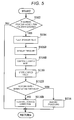
- step S102 in Fig. 5 it is first determined whether the learning processing execution condition is satisfied. If it is determined that the learning processing execution condition is satisfied (if YES), the EGR valve 16 is brought into the fully opened state (see step S104 in Fig. 5 ), and the pressure in front and at the rear of the EGR valve 16 is measured (see step S106B in Fig. 5 ).
- upstream-side pressure for convenience of the description
- downstream-side pressure for convenience of the description
- the EGR control based on the model control is executed. Accordingly, instead of the actually measured value by using the pressure sensor, a calculated value that is arithmetically computed in an execution process of the model control is used as the upstream-side pressure, and the actually measured value by the intake pressure sensor 26 is used as the downstream-side pressure.
- the clogging rate as the clogging rate learned value that is computed as described above is stored and retained as the new clogging rate learned value in the learned value storage area that is secured in advance in the appropriate storage area of the electronic control unit 4. In this way, the last clogging rate learned value is updated (see step S110 in Fig. 5 ).
- step S108B it is determined whether the clogging rate Cdp computed in step S108B exceeds a differential pressure clogging rate determination threshold Cref-dp. If it is determined that the clogging rate Cdp exceeds the differential pressure clogging rate determination threshold Cref-dp (if YES), the subroutine proceeds to the processing in step S114. On the other hand, if it is determined that the clogging rate Cdp does not exceed the differential pressure clogging rate determination threshold Cref-dp (if NO), the subroutine proceeds to the processing in step S116B.
- step S114 similar to what has been described by using Fig. 2 , the predetermined warning processing, such as lighting of the lighting element like the MIL lamp (not depicted) or the like or sounding of the sounding element, is executed so as to warn the occupant of the fact that the operation of the EGR device is in the abnormal state.
- the predetermined warning processing such as lighting of the lighting element like the MIL lamp (not depicted) or the like or sounding of the sounding element
- step S116B correcting processing on the flow rate control of the circulated exhaust gas by the EGR control processing, which is separately executed in the electronic control unit 4, (hereinafter referred to as the "flow rate control correction" for convenience of the description) is executed on the basis of the clogging rate computed in step S108B, a series of the processing is terminated, and the subroutine once returns to the undepicted main routine.
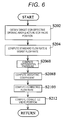
- Fig. 6 a specific processing procedure of the flow rate control correction is depicted in the subroutine flowchart, and the content thereof will hereinafter be described with reference to the same drawing.
- the target EGR effective opening area and the actual EGR valve position are obtained (see step S202 in Fig. 6 ). Then, the standard flow rate and the worst flow rate are computed (see step S204 in Fig. 6 ).
- the weighting coefficient in this second example is preferably computed by using a computing equation that is set on the basis of a test result or a simulation result in consideration of the particular specification of the EGR device and that is set such that the weighting coefficient is defined for each of various differential pressure.
- weighting coefficient computation map for convenience of the description
- a map that uses the differential pressure as an input parameter and from which the corresponding weighting coefficient can be read on the basis of the computing equation and to store the map in advance in an appropriate storage area of the electronic control unit 4, so as to define the weighting coefficient by using the map.
- a corrected flow rate is computed by using the weighting coefficient obtained as described above (see step S210B in Fig. 5 ).
- the flow rate difference as the difference between the standard flow rate and the worst flow rate obtained in above step S204 is computed.
- the corrected flow rate is obtained by multiplying the computed flow rate difference by the weighting coefficient computed in step S208B and adding the worst flow rate obtained in above step S204 to a multiplication result.
- the flow rate that is computed by using the weighting coefficient as 1 and adding the worst flow rate to the flow rate difference becomes the so-called target flow rate that should flow through the EGR valve 16 in the conventional EGR control processing, in which the correction as in the invention is not made.
- valve position of the EGR valve 16 that is required to obtain the corrected flow rate is computed similar to the conventional manner (see step S212 in Fig. 6 ), a series of the processing is terminated, and the subroutine once returns to the undepicted main routine.
- the internal combustion engine in the invention is not limited to the diesel engine 3 as long as the exhaust gas recirculation device 101 is mounted in the vehicle, and the invention can also be applied to the vehicle using a gasoline engine in a similar manner.
- the invention is suitable for the EGR device that is desired to reliably detect the reduction in the flow rate of the circulated exhaust gas in conjunction with the secular change and compensate the reduction.
Landscapes
- Engineering & Computer Science (AREA)
- Chemical & Material Sciences (AREA)
- Combustion & Propulsion (AREA)
- Mechanical Engineering (AREA)
- General Engineering & Computer Science (AREA)
- Exhaust-Gas Circulating Devices (AREA)
- Output Control And Ontrol Of Special Type Engine (AREA)
Description
- The invention relates to operation control of an exhaust gas recirculation device for an internal combustion engine and, in particular, to operation control for suppressing and preventing degradation of operation efficiency due to secular change and for improving reliability of an operation of the device.
- As it has widely been known, an exhaust gas recirculation device (an EGR device) is used to improve an emission property and the like in an internal combustion engine, and various suggestions and implementation of a configuration, operation control, and the like thereof have conventionally been made (see
PTL 1, for example). - In such an exhaust gas recirculation device, exhaust gas is circulated to an intake side via a communication passageway for communicating between an intake pipe and an exhaust pipe, and a circulation amount is usually adjusted by adjusting an opening degree of an EGR valve that is provided in the communication passageway.
- By the way, it is needless to say that the exhaust gas to be circulated contains soot and the like. Along with use of the device for a long period, for example, the soot and the like are gradually adhered to an inner wall of the EGR valve, which results in a reduction in an effective opening area thereof and also results in degradation of operation efficiency of the entire device. Accordingly, it may not be possible to guarantee sufficient performance of the device.
- As a measure against such a phenomenon, for example, a method for compensating for a change in a flow rate of circulated exhaust gas, which is caused by the gradual reduction in the effective opening area of the EGR valve, by executing flow rate control based on an I term (an integral term) component of PID control is considered.
- In addition, a method for estimating in advance a magnitude of the change in the flow rate of the circulated exhaust gas, which is caused by the gradual reduction in the effective opening area of the EGR valve, and executing the flow rate control of the circulated exhaust gas by adding an estimated magnitude is considered.
- [PTL 1]
JP-A-2004-245118 pages 5 to 9,Fig. 1 to Fig. 6 ) - However, the former flow rate control that is based on the I term (the integral term) of the PID control has such a disadvantage that transient responsiveness is degraded as a degree of contribution of the I term component in the flow rate control is increased. Accordingly, flow rate control in which both of the responsiveness and the contribution are compromised has to be adopted in reality. Thus, such a problem arises that satisfying control cannot always be realized.
- Meanwhile, as in the latter case, in the method for estimating in advance the magnitude of the change in the flow rate of the circulated exhaust gas, an estimated value is used. Thus, such a problem arises that an actual change is not always compensated in a sufficient manner.
- The invention has been made in view of the above circumstances and therefore provides an EGR control method and an EGR device capable of reliably detecting a reduction in a flow rate of circulated exhaust gas that is associated with secular change and capable of compensating for the reduction in the flow rate.
- In order to achieve the above purpose of the invention, an EGR control method according to the invention is
an EGR control method in an EGR device that is configured to be able to circulate some of exhaust gas of an internal combustion engine to an intake side of the internal combustion engine, and
is configured to correct a circulation amount of the exhaust gas to the intake side by an EGR valve for controlling the circulation amount of the exhaust gas in accordance with a degree of degradation of a distribution property of the exhaust gas in the EGR valve when the distribution property falls below a specified standard. - In addition, in order to achieve the above purpose of the invention, an EGR device according to the invention is an EGR device configured to be provided with an EGR valve that is configured to be able to control a valve position in a communication passageway for communicating between an exhaust pipe and an intake pipe of an internal combustion engine and to change a communication state of the communication passageway by operation control of the EGR valve by an electronic control unit, so as to be able to circulate some of exhaust gas to an intake side, in which
the electronic control unit is
configured to correct a circulation amount of the exhaust gas by the EGR valve in accordance with a degree of degradation of a distribution property of the exhaust gas in the EGR valve when it is determined that the distribution property falls below a specified standard. - According to the invention, the reduction in the flow rate in the EGR valve is detected on the basis of whether the distribution property of the circulated exhaust gas in the EGR valve is equal to a below the standard, and the flow rate of the circulated exhaust gas is corrected in accordance with the degree of the degradation of the distribution property. Thus, unlike the conventional art that uses an estimated value or the like, the reduction in the flow rate in the EGR valve, in other words, occurrence of clogging caused by soot and the like can reliably be comprehended, and suitable compensation for the reduction in the flow rate can be made. Therefore, an effect of being able to improve stability and reliability of an operation of the device is exerted.
-
-
Fig. 1 is a configuration diagram for depicting a configuration example of a fuel injection controller of a common rail type as a fuel injection controller for an internal combustion engine that is provided with an EGR device in an embodiment of the invention. -
Fig. 2 is a configuration diagram for depicting a configuration example of the EGR device in the embodiment of the invention. -
Fig. 3 is a subroutine flowchart for depicting a procedure of a first example of EGR control processing in the embodiment of the invention that is executed in the EGR device depicted inFig. 2 . -
Fig. 4 is a subroutine flowchart for depicting a procedure of flow rate control correction processing that is executed in the EGR control processing in the first example. -
Fig. 5 is a subroutine flowchart for depicting a procedure of a second example of the EGR control processing in the embodiment of the invention that is executed in the EGR device depicted inFig. 2 . -
Fig. 6 is a subroutine flowchart for depicting a procedure of flow rate control correction processing that is executed in the EGR control processing in the second example. - A description will hereinafter be made on an embodiment of the invention with reference to
Fig. 1 to Fig. 6 . - Noted that members, arrangement, and the like, which will be described below, do not limit the invention and various modifications can be made to the invention within the scope of the gist of the invention.
- First, a description will be made on a configuration example of a fuel injection controller of a common rail type, for which an EGR controller is used, with reference to
Fig. 1 , an EGR control method for an internal combustion engine in the embodiment of the invention being used for the EGR device. - The fuel injection controller of the common rail type in the embodiment of the invention is configured by including as main components: a high-
pressure pump device 50 that pressure-feeds high pressure fuel; acommon rail 1 that stores the high pressure fuel pressure-fed from this high-pressure pump device 50; plural fuel injection valves 2-1 to 2-n that inject and supply the high pressure fuel supplied from thiscommon rail 1 to cylinders of a diesel engine (hereinafter referred to as an "engine") 3 as the internal combustion engine; and an electronic control unit (indicated as "ECU" inFig. 1 ) 4 that executes fuel injection control processing, EGR control processing for the internal combustion engine, which will be described below, and the like. - Such a configuration itself is the same as a basic configuration of the fuel injection controller of the common rail type of this type that has conventionally and widely been known.
- The high-
pressure pump device 50 has a known or well-known configuration that includes asupply pump 5, ametering valve 6, and a high-pressure pump 7 as main components. - In such a configuration, fuel in a
fuel tank 9 is pumped up by thesupply pump 5 and supplied to the high-pressure pump 7 via themetering valve 6. An electromagnetic proportional control valve is used as themetering valve 6. By controlling an energization amount thereof by theelectronic control unit 4, a flow rate of the supplied fuel to the high-pressure pump 7, in other words, a discharge amount of the high-pressure pump 7 is adjusted. - Noted that a
return valve 8 is provided between an output side of thesupply pump 5 and thefuel tank 9, so as to be able to return a surplus of the fuel on the output side of thesupply pump 5 to thefuel tank 9. - In addition, the
supply pump 5 may be provided as a separate component from the high-pressure pump device 50 on an upstream side of the high-pressure pump device 50, or may be provided in thefuel tank 9. - The fuel injection valves 2-1 to 2-n are respectively provided for the cylinders of the
engine 3, are each supplied with the high pressure fuel from thecommon rail 1, and each inject the fuel through injection control by theelectronic control unit 4. - The
electronic control unit 4 is, for example, centered on a microcomputer (not depicted) that has a known or well-known configuration, has memory elements (not depicted) such as a RAM and a ROM, and is configured by including: a circuit (not depicted) for energizing and driving the fuel injection valves 2-1 to 2-n; and a circuit (not depicted) for energizing and driving themetering valve 6 and the like, as main components. - Such an
electronic control unit 4 receives a detection signal of apressure sensor 11 that detects pressure of thecommon rail 1, and also receives various detection signals, such as an engine speed, an accelerator pedal position, an ambient temperature, and atmospheric pressure, so as to use these signals for operation control and fuel injection control of theengine 3 and further for EGR control processing and the like in the embodiment of the invention. -
Fig. 2 depicts a configuration example of an exhaustgas recirculation device 101 that is provided for emission reduction of theengine 3 and the like, and a configuration thereof and the like will hereinafter be described with reference to the same drawing. - First, an
intake pipe 12 for taking air that is required to combust the fuel and anexhaust pipe 13 for discharging exhaust gas are respectively connected to anintake manifold 14a and anexhaust manifold 14b of theengine 3. - A
communication passageway 15 for communicating between theexhaust pipe 13 and theintake pipe 12 are provided at appropriate positions of theexhaust pipe 13 and theintake pipe 12, and anEGR cooler 17 for cooling passing exhaust gas and anEGR valve 16 for adjusting a communication state of thecommunication passageway 15, in other words, a circulation amount of the exhaust gas are sequentially disposed from theexhaust pipe 13 side in the middle of thiscommunication passageway 15. - In addition, a
variable turbocharger 18 that includes: avariable turbine 19 provided on a downstream side of thecommunication passageway 15 in theexhaust pipe 13; and acompressor 20 provided on an upstream side of thecommunication passageway 15 in theintake pipe 12, as main components, and that has a known or well-known configuration is provided. Thecompressor 20 rotates by rotary power that is obtained from thevariable turbine 19, and compressed air is delivered as intake air to theintake manifold 14a. - Furthermore, the
intake pipe 12 is provided with anintercooler 21 for cooling the intake air at an appropriate position between thecommunication passageway 15 described above and thevariable turbocharger 18. - An
intake throttle valve 22 for adjusting an intake air amount is provided between thisintercooler 21 and thecommunication passageway 15. - Moreover, a
filter 23 for cleaning the intake air is provided on an upstream side of theintake pipe 12, and anair mass sensor 24 for detecting the intake air amount that flows in via thefilter 23 is provided on a downstream side thereof. - In addition, in the
intake pipe 12, an intakeair temperature sensor 25 for detecting a temperature of the intake air of theengine 3 is provided between theintercooler 21 and theintake throttle valve 22, and anintake pressure sensor 26 for detecting intake pressure of theintake manifold 14a is provided on a downstream side of theintake throttle valve 22. - Meanwhile, a
λ sensor 27 is provided on a downstream side of thevariable turbine 19 in theexhaust pipe 13. - In addition, an
exhaust pressure sensor 28 for detecting exhaust pressure and anexhaust temperature sensor 29 for detecting a temperature of the exhaust gas are provided at appropriate positions on an upstream side of thevariable turbine 19 in theexhaust pipe 13. - Detection signals of these
air mass sensor 24, intakeair temperature sensor 25,intake pressure sensor 26,λ sensor 27,exhaust pressure sensor 28, andexhaust temperature sensor 29 are input to theelectronic control unit 4 and used for the fuel injection control processing, the EGR control processing for the internal combustion engine in examples of the invention, which will be described below, and the like. - Next, a description will be made on the EGR control processing for the internal combustion engine in the embodiment of the invention that is executed by the
electronic control unit 4 with reference toFig. 2 to Fig. 6 . - First, an outline of the EGR control method for the internal combustion engine in the embodiment of the invention will be described.
- In the EGR control method for the internal combustion engine in the embodiment of the invention, degradation of a distribution property of circulated exhaust gas, which is caused by soot and the like that are gradually adhered to an inner wall of the
EGR valve 16 along with use of the EGR device for a long period, in other words, clogging of theEGR valve 16 is detected, and flow rate control thereof is corrected in accordance with a degree of clogging of theEGR valve 16. - In an EGR control method in a first example, which will specifically be described below, clogging of the
EGR valve 16 is detected on the basis of a change in a flow rate in theEGR valve 16, and the flow rate control is corrected. - In addition, in an EGR control method in a second example, which will be described below, clogging of the
EGR valve 16 is detected on the basis of differential pressure between front and rear of theEGR valve 16, and the flow rate control is corrected. - First, it is assumed that the EGR control processing based on a conventional method is executed in the
electronic control unit 4 as the main component of the EGR device in the embodiment of the invention. - Here, as the EGR control processing that is based on the conventional method, a basic EGR control method in which a target value of a control target, such as the
EGR valve 16, corresponding to an operation state of theengine 3 is arithmetically computed on the basis of measured values detected by the various sensors, such as theair mass sensor 24, the intakeair temperature sensor 25, and theintake pressure sensor 26, as described above, and the like and in which feedback control is executed to achieve the desired target value can be raised (hereinafter such EGR control will be referred to as "normal feedback control" for convenience of the description). - In addition, as the EGR control processing based on the conventional method, it may be based on so-called model control, and such model control has conventionally and widely been known, for example, in
JP-T-2005-504210 - More specifically, as a basis of the EGR control based on the model control, an EGR system that includes the
variable turbocharger 18, theintake pipe 12, theexhaust pipe 13, and the like is modeled on the basis of thermodynamics and the like, data of the actually obtained flow rate, differential pressure, and the like are input to the model, a model value as a control target value in the EGR system is obtained, and operation control of the required control target is executed such that an operation state of the EGR system reaches a state with the model value. - Noted that, in the model control, a physical quantity that is set as the control target value (the model value) is the flow rate of the circulated exhaust gas, a valve position of the
EGR valve 16, supercharging pressure, or the like, for example. Meanwhile, any of various values may be set as the model value in accordance with how to set the model on the basis of thermodynamics and the like. Thus, the model value does not have to be limited to a particular value and only has to be a value, with which the EGR system is modeled on the basis of thermodynamics and the like and the flow rate control of the circulated exhaust gas is executed on the basis of the model. - The EGR device in the embodiment of the invention depicted in
Fig. 2 has a configuration in which the onevariable turbocharger 18 is provided, but may have a so-called two-stage configuration in which the two variable turbochargers are provided. - Noted that, in the first and second examples of the EGR control processing, which will be described below, a description will be made with an assumption that the conventional EGR control processing is based on the so-called model control. When it is assumed that the EGR control is based on the "normal feedback control", a description on a different processing procedure and the like will be added upon necessary.
- Under such an assumption, a description will be made on the first example of the EGR control processing in the embodiment of the invention, which is executed by the
electronic control unit 4, with reference to subroutine flowcharts depicted inFig. 3 andFig. 4 . - Noted that each of these subroutine flowcharts is executed in the
electronic control unit 4 as one of various types of subroutine processing that are executed in a main routine of the conventional EGR control, which is based on the model control and is separately executed as described above. - When the processing by the
electronic control unit 4 is initiated, it is first determined whether a learning processing execution condition is satisfied (see step S102 inFig. 3 ). - That is, in the embodiment of the invention, as will be described below, so-called learning processing is executed in which, as an index indicative of the distribution property of the circulated exhaust gas (easiness of flowing of the circulated exhaust gas) in the
EGR valve 16, in other words, a degree of clogging, a clogging rate is defined and obtained at appropriate time intervals and in which the clogging rate is stored and updated as a so-called learned value. It is determined in step S102 whether a specified condition that is appropriate for execution of processing in step S104 onward as the learning processing is satisfied. - Here, as the appropriate condition for initiation of the learning processing, specifically, it is at least required to bring the accelerator pedal position to zero during traveling of a vehicle and to bring fuel injection to the
engine 3 by the fuel injection valves 2-1 to 2-n into a state of no injection. This is set for a purpose of avoiding as much as possible a situation where a traveling state is actively degraded. - The condition that is appropriate for the initiation of the learning processing does not have to be limited to the above-described condition. It is preferred to appropriately set another condition that does not affect an operation state or the traveling state of the vehicle as much as possible and that is required to stably and reliably execute the learning processing in consideration of a particular specification and the like of the vehicle.
- Meanwhile, if it is determined in step S102 that the learning processing execution condition is not satisfied (if NO), a series of the processing is terminated as it is in a state where following processing should not be executed, and the subroutine once returns to the undepicted main routine.
- On the other hand, if it is determined in step S102 that the learning processing execution condition is satisfied (if YES), the subroutine proceeds to the processing in step S104, which will be described next.
- Next, the
EGR valve 16 is brought into a fully opened state (see step S104 inFig. 3 ), and the flow rate of the circulated exhaust gas that flows through theEGR valve 16 is measured (see step S106 inFig. 3 ). - Here, in the embodiment of the invention, as will be described below, measurement of the flow rate of the circulated exhaust gas is realized by calculation using a flow rate computing equation, and actually measured values are used only for some of physical elements that are used in the flow rate computing equation.
- That is, in the embodiment of the invention, a flow rate dmEGR of the circulated exhaust gas is obtained by the flow rate computing equation described below that is based on a so-called throttle equation.

- In the above computing equation, Pus and Tus respectively represent the exhaust pressure and an exhaust temperature on an upstream side of the
communication passageway 15, that is, in the vicinity of theexhaust manifold 14b. - In addition, Pds and Tds respectively represent the intake pressure and the intake air temperature on a downstream side of the
communication passageway 15, that is, in the vicinity of theintake manifold 14a. - Furthermore, A represents an opening area of the
EGR valve 16. - In the embodiment of the invention, it is assumed that opening/closing control of the
EGR valve 16 based on the model control is executed as described above. Thus, instead of the actually measured values, the exhaust pressure Pus and the exhaust temperature Tus are so-called model values that are obtained by calculation in the model control. Meanwhile, the actually measured values by theintake pressure sensor 26 and the intakeair temperature sensor 25 are respectively used as the intake pressure Pds and the intake air temperature Tds. - Noted that, in the case where the EGR control is based on the "normal feedback control", the actually measured values that are detected by the
exhaust pressure sensor 28 and theexhaust temperature sensor 29 are respectively used as the above-described exhaust pressure Pus and exhaust temperature Tus. - In addition, a correlation between a valve position of an undepicted valve and the opening area A in the
EGR valve 16 is comprehended in advance, and is stored and retained in an appropriate storage area of theelectronic control unit 4. Accordingly, the opening area A with respect to the valve position at a time point when the processing in step S106 is executed is computed on the basis of the stored correlation. - Next, the clogging rate is computed (see step S108 in
Fig. 3 ). - In the embodiment of the invention, the clogging rate is obtained by indexing the degree of clogging on the inside of the
EGR valve 16, which is caused by the soot and the like. In a case of this first example, the clogging rate is expressed as a ratio of the flow rate of the circulated exhaust gas in the fully opened state of theEGR valve 16 at a time when the EGR device according to the invention is started to be used for the first time to the flow rate of the circulated exhaust gas at a current time point, which has been obtained in step S106. - That is, in cases where the flow rate of the circulated exhaust gas in the fully opened state of the
EGR valve 16 at the time when the EGR device is started to be used for the first time is described as "dmEGRest" for convenience of the description, where the flow rate of the circulated exhaust gas at the current time point, which has been obtained in step S106, is described as "dmEGRact" for convenience of the description, and where the clogging rate computed on the basis of the flow rates is described as "Cfl" for convenience of the description, it is computed as the clogging rate Cfl = dmEGRest/dmEGRact. - Noted that the flow rate of the circulated exhaust gas in the fully opened state of the
EGR valve 16 at the time when the EGR device is started to be used for the first time is measured in advance, is appropriately stored and retained in an appropriate storage area of theelectronic control unit 4, and can be used for the above-described calculation. - Next, the clogging rate as a clogging rate learned value, which has been computed as described above, is stored and retained as a new clogging rate learned value in a learned value storage area that is secured in advance in an appropriate storage area of the
electronic control unit 4. In this way, the last clogging rate learned value is updated (see step S110 inFig. 3 ). - Next, it is determined whether the clogging rate Cfl computed in step S108 exceeds a flow rate clogging rate determination threshold Cref-fl. If it is determined that the clogging rate Cfl exceeds the flow rate clogging rate determination threshold Cref-fl (if YES), the subroutine proceeds to the processing in step S114. On the other hand, if it is determined that the clogging rate Cfl does not exceed the flow rate clogging rate determination threshold Cref-fl (if NO), the subroutine proceeds to the processing in step S116.
- In step S114, because an original normal operation of the EGR device cannot be maintained in a state where the clogging rate Cfl exceeds the flow rate clogging rate determination threshold Cref-fl, predetermined warning processing, such as lighting of a lighting element like an MIL lamp (not depicted) or the like or sounding of a sounding element, is executed so as to warn an occupant of a fact that the operation of the EGR device is in an abnormal state.
- Meanwhile, in step S116, correcting processing on the flow rate control of the circulated exhaust gas by the EGR control processing, which is separately executed in the
electronic control unit 4, (hereinafter referred to as "flow rate control correction" for convenience of the description) is executed on the basis of the clogging rate computed in step S108, a series of the processing is terminated, and the subroutine once returns to the undepicted main routine. - In
Fig. 4 , a specific processing procedure of flow rate control correction is depicted in a subroutine flowchart, and contents thereof will hereinafter be described with reference to the same drawing. - First, when the processing by the
electronic control unit 4 is initiated, a target EGR effective opening area and an actual EGR valve position are obtained (see step S202 inFig. 4 ). - First, the target EGR effective opening area is an opening area that is actually required for the
EGR valve 16 to make the circulated exhaust gas at a target flow rate flow through theEGR valve 16. This target EGR effective opening area is usually expressed as a distribution area of the circulated exhaust gas in a plane that is orthogonal to a distribution direction of the circulated exhaust gas. - In the embodiment of the invention, such a target EGR effective opening area is computed on the basis of a predetermined arithmetic equation in the EGR control processing, which has been described above as a precondition and is based on the so-called model control.
- Meanwhile, the actual EGR valve position is an actual position of the valve (not depicted) that is provided in the
EGR valve 16. Because such an actual EGR valve position is correlated with a magnitude of an energizing current to theEGR valve 16, a correlation therebetween is obtained in advance in the embodiment of the invention. For example, a map that has the energizing current as an input parameter and from which the corresponding valve position can be read is stored in an appropriate storage area of theelectronic control unit 4. In this way, the actual EGR valve position can be obtained from the magnitude of the energizing current to theEGR valve 16 at a time when the processing in step S202 is executed. Here, the valve position is displayed such that, for example, the valve position at which theEGR valve 16 is in a fully closed state is set as a valve position 0, the valve position at which theEGR valve 16 is in the fully opened state is set as 100, and the valve position therebetween is appropriately divided in accordance with the position of the undepicted valve on the inside (for example, the magnitude of the energizing current for convenience of the description). Thus, the valve position does not always correspond to the actual opening area of theEGR valve 16 described above. - Next, a standard flow rate and a worst flow rate are computed (see step S204 in
Fig. 4 ). - Here, the standard flow rate refers to a flow rate of the circulated exhaust gas that is assumed to flow through the
EGR valve 16 in the EGR control state at a current time point in the case where theEGR valve 16 has a property of a so-called standard product. - This standard flow rate is defined to have a fixed correlation with a combination of the target EGR effective opening area and the actual EGR valve position obtained in above step S202. In the embodiment of the invention, a map (hereinafter referred to as a "standard flow rate map" for convenience of the description) that is configured in advance that various combinations of the target EGR effective opening area and the actual EGR valve position are input on the basis of such a correlation and that the standard flow rate with respect to each of the combinations can be read is stored in an appropriate storage area of the
electronic control unit 4. In this way, the standard flow rate that corresponds to the combination of the target EGR effective opening area and the actual valve position obtained in above step S202 can be obtained. - Noted that the correlation between the standard flow rate and the combination of the target EGR effective opening area and the actual EGR valve position is preferably determined on the basis of a test result, a simulation result, or the like in consideration of a particular specification and the like of the device.
- Meanwhile, the worst flow rate refers to a minimum flow rate at which an EGR operation can be maintained in the case where the flow rate of the circulated exhaust gas of the
EGR valve 16 is reduced due to secular change or the like. - Similar to the standard flow rate described above, such a worst flow rate has a fixed correlation with the combination of the target EGR effective opening area and the actual EGR valve position obtained in above step S202. Also, similar to a case of the standard flow rate, a map (hereinafter referred to as a "worst flow rate map" for convenience of the description) that is configured in advance that the various combinations of the target EGR effective opening area and the actual EGR valve position are input and that the worst flow rate corresponding to each of the combinations can be read is stored in an appropriate storage area of the
electronic control unit 4. In this way, the worst flow rate that corresponds to the combination of the target EGR effective opening area and the actual valve position obtained in above step S202 can be obtained. - Noted that, similar to a case of the standard flow rate map described above, the correlation between the worst flow rate and the combination of the target EGR effective opening area and the actual EGR valve position is preferably determined on the basis of a test result, a simulation result, or the like in consideration of the particular specification and the like of the device.
- Next, a flow rate difference is computed (see step S206 in
Fig. 4 ). - That is, the flow rate difference as a difference between the standard flow rate and the worst flow rate that have been obtained as described above is computed.
- Next, a weighting coefficient that is used at a time when the flow rate control is corrected is computed (see step S208 in
Fig. 4 ). - That is, first, the target value of the flow rate of the circulated exhaust gas that should flow through the EGR valve 16 (hereinafter a "target flow rate" for convenience of the description) is arithmetically computed in the EGR control that is based on the model control in the embodiment of the invention. However, as for this target flow rate, the reduction in the flow rate of the circulated exhaust gas flowing through the
EGR valve 16, which is caused by clogging of theEGR valve 16 and which is attempted to be solved in the invention of the subject application, is not taken into consideration. - The weighting coefficient can be used to correct the flow rate of the circulated exhaust gas that should flow through the
EGR valve 16 and that is defined by the conventional EGR control processing in accordance with the clogging rate and thus to compensate for the reduction in the flow rate, which is caused by clogging of the soot and the like in theEGR valve 16. - In the embodiment of the invention, the weighting coefficient is defined in accordance with the clogging rate that is obtained as the learned value. That is, when the weighting coefficient is computed, it is preferred that a computing equation for computing the preferred weighting coefficient with respect to the clogging rate is set on the basis of a test result or a simulation result in consideration of the particular specification of the EGR device and that the weighting coefficient is computed by the computing equation. In addition, a so-called map (hereinafter referred to as a "weighting coefficient computation map" for convenience of the description) configured, for example, that the clogging rate is used as an input parameter and that the weighting coefficient corresponding to each of the various clogging rates can be read is preferably created on the basis of the computing equation and stored in advance in an appropriate storage area of the
electronic control unit 4, so as to define the weighting coefficient by using the map. - Next, a corrected flow rate is computed by using the weighting coefficient that has been obtained as described above (see step S210 in
Fig. 4 ). - That is, the corrected flow rate is obtained by multiplying the flow rate difference computed in above step S206 by the weighting coefficient and adding the worst flow rate obtained in above step S204 to a multiplication result.
- Noted that, in a computation procedure of the above-described corrected flow rate, the flow rate that is computed by using the weighting coefficient as 1 and adding the worst flow rate to the flow rate difference becomes the so-called target flow rate that should flow through the
EGR valve 16 in the conventional EGR control processing, in which the flow rate correction as in the invention is not made. - Next, the valve position of the
EGR valve 16 that is required to obtain the corrected flow rate computed as described above is computed similar to a conventional manner (see step S212 inFig. 4 ), a series of the processing is terminated, and the subroutine once returns to the undepicted main routine. - Noted that the EGR control, which is based on the model control as the precondition in the embodiment of the invention, is executed in the undepicted main routine and the EGR control is executed such that the valve position of the
EGR valve 16 becomes a corrected valve position computed in step S212. - Next, the description will be made on the second example of the EGR control method with reference to
Fig. 5 andFig. 6 . - Noted that, in subroutine flowcharts depicted in
Fig. 5 andFig. 6 , the same contents of processing as those of the processing depicted inFig. 3 andFig. 4 above are denoted by the same reference signs and the detailed description thereon will not be repeated. Hereinafter, the description will be centered on different points. - In summary, in the EGR control method in this second example, clogging of the
EGR valve 16 is detected on the basis of the differential pressure between the front and the rear of theEGR valve 16, and the flow rate control is corrected. - Noted that, because preconditions such as the device are basically the same as those in the above first example, the description will not be repeated.
- When the processing by the
electronic control unit 4 is initiated, it is first determined whether the learning processing execution condition is satisfied (see step S102 inFig. 5 ). If it is determined that the learning processing execution condition is satisfied (if YES), theEGR valve 16 is brought into the fully opened state (see step S104 inFig. 5 ), and the pressure in front and at the rear of theEGR valve 16 is measured (see step S106B inFig. 5 ). - That is, pressure in the vicinity of the
exhaust manifold 14b of the engine 3 (hereinafter referred to as "upstream-side pressure" for convenience of the description) and pressure in the vicinity of theintake manifold 14a (hereinafter referred to as "downstream-side pressure" for convenience of the description) are respectively obtained as the pressure on the upstream side of theEGR valve 16 and the pressure on the downstream side of theEGR valve 16. - In the embodiment of the invention, as described above, it is assumed that the EGR control based on the model control is executed. Accordingly, instead of the actually measured value by using the pressure sensor, a calculated value that is arithmetically computed in an execution process of the model control is used as the upstream-side pressure, and the actually measured value by the
intake pressure sensor 26 is used as the downstream-side pressure. - Next, the clogging rate is computed (see step S108B in
Fig. 5 ). - That is, as for the clogging rate of the
EGR valve 16 in this second example, when the upstream-side pressure, the downstream-side pressure, and the clogging rate are respectively represented by "Pus", "Pds", and "Cdp", the clogging rate Cdp is obtained by the following equation.
- Next, the clogging rate as the clogging rate learned value that is computed as described above is stored and retained as the new clogging rate learned value in the learned value storage area that is secured in advance in the appropriate storage area of the
electronic control unit 4. In this way, the last clogging rate learned value is updated (see step S110 inFig. 5 ). - Next, it is determined whether the clogging rate Cdp computed in step S108B exceeds a differential pressure clogging rate determination threshold Cref-dp. If it is determined that the clogging rate Cdp exceeds the differential pressure clogging rate determination threshold Cref-dp (if YES), the subroutine proceeds to the processing in step S114. On the other hand, if it is determined that the clogging rate Cdp does not exceed the differential pressure clogging rate determination threshold Cref-dp (if NO), the subroutine proceeds to the processing in step S116B.
- In step S114, similar to what has been described by using
Fig. 2 , the predetermined warning processing, such as lighting of the lighting element like the MIL lamp (not depicted) or the like or sounding of the sounding element, is executed so as to warn the occupant of the fact that the operation of the EGR device is in the abnormal state. - Meanwhile, in step S116B, correcting processing on the flow rate control of the circulated exhaust gas by the EGR control processing, which is separately executed in the
electronic control unit 4, (hereinafter referred to as the "flow rate control correction" for convenience of the description) is executed on the basis of the clogging rate computed in step S108B, a series of the processing is terminated, and the subroutine once returns to the undepicted main routine. - In
Fig. 6 , a specific processing procedure of the flow rate control correction is depicted in the subroutine flowchart, and the content thereof will hereinafter be described with reference to the same drawing. - Noted that, the same contents of the processing as those of the processing depicted in above
Fig. 4 are denoted by the same reference signs and the detailed description thereon will not be repeated. Hereinafter, the description will be centered on different points. - First, when the processing by the
electronic control unit 4 is initiated, the target EGR effective opening area and the actual EGR valve position are obtained (see step S202 inFig. 6 ). Then, the standard flow rate and the worst flow rate are computed (see step S204 inFig. 6 ). - Next, the differential pressure is computed (see step S206B in
Fig. 6 ). - In this case, because the differential pressure has already been computed in above step S106B, it is enough to use a computation result thereof.
- Next, a weighting coefficient that is used at the time when the flow rate control is corrected is computed (see step S208B in
Fig. 6 ). - The weighting coefficient in this second example is preferably computed by using a computing equation that is set on the basis of a test result or a simulation result in consideration of the particular specification of the EGR device and that is set such that the weighting coefficient is defined for each of various differential pressure.
- Here, it is also preferred to create a map (hereinafter referred to as a "weighting coefficient computation map" for convenience of the description) that uses the differential pressure as an input parameter and from which the corresponding weighting coefficient can be read on the basis of the computing equation and to store the map in advance in an appropriate storage area of the
electronic control unit 4, so as to define the weighting coefficient by using the map. - Next, a corrected flow rate is computed by using the weighting coefficient obtained as described above (see step S210B in
Fig. 5 ). - That is, the flow rate difference as the difference between the standard flow rate and the worst flow rate obtained in above step S204 is computed. Then, the corrected flow rate is obtained by multiplying the computed flow rate difference by the weighting coefficient computed in step S208B and adding the worst flow rate obtained in above step S204 to a multiplication result.
- Noted that, in the computation procedure of the above-described corrected flow rate, the flow rate that is computed by using the weighting coefficient as 1 and adding the worst flow rate to the flow rate difference becomes the so-called target flow rate that should flow through the
EGR valve 16 in the conventional EGR control processing, in which the correction as in the invention is not made. - Next, the valve position of the
EGR valve 16 that is required to obtain the corrected flow rate is computed similar to the conventional manner (see step S212 inFig. 6 ), a series of the processing is terminated, and the subroutine once returns to the undepicted main routine. - The description has been made on each of the above-described first example and second example with the assumption of the configuration that the
diesel engine 3 as the internal combustion engine is used. However, the internal combustion engine in the invention is not limited to thediesel engine 3 as long as the exhaustgas recirculation device 101 is mounted in the vehicle, and the invention can also be applied to the vehicle using a gasoline engine in a similar manner. - The invention is suitable for the EGR device that is desired to reliably detect the reduction in the flow rate of the circulated exhaust gas in conjunction with the secular change and compensate the reduction.
-
- 1: common rail
- 3: engine
- 4: electronic control unit
- 16: EGR valve
Claims (10)
- An EGR control method in an EGR device that is configured to be able to circulate some of exhaust gas of an internal combustion engine to an intake side of the internal combustion engine, the EGR control method characterized by
correcting a circulation amount of the exhaust gas by an EGR valve for controlling the circulation amount of the exhaust gas to the intake side in accordance with a degree of degradation of a distribution property of the exhaust gas in the EGR valve when the distribution property falls below a specified standard. - The EGR control method according to claim 1 characterized in that the distribution property of the exhaust gas is expressed by a clogging rate that is obtained as a ratio of a flow rate of the exhaust gas at a time when the EGR valve is started to be used to a flow rate of the exhaust gas in the EGR valve at a time when the distribution property is determined and in that it is determined that the distribution property falls below the specified standard in the case where the clogging rate exceeds a determination threshold.
- The EGR control method according to claim 1 characterized in that the distribution property of the exhaust gas is expressed by a clogging rate that is obtained as a ratio of pressure on an upstream side of EGR valve to pressure on a downstream side of the EGR valve at a time when the distribution property is determined and in that it is determined that the distribution property falls below the specified standard in the case where the clogging rate exceeds a determination threshold.
- The EGR control method according to claim 2 or claim 3 characterized in that a target value of circulated exhaust gas that is computed on the basis of an operation state of the EGR device and that should flow through the EGR valve is corrected by a weighting coefficient that is defined in accordance with the clogging rate with no consideration of a reduction in the flow rate of the circulated exhaust gas flowing through the EGR valve and in that a valve position of the EGR valve is changed in accordance with a post-correction flow rate.
- The EGR control method according to claim 4 characterized in that required warning processing is executed when the distribution property of the exhaust gas in the EGR valve for controlling the circulation amount of the exhaust gas to the intake side falls below the specified standard.
- An EGR device configured to be provided with an EGR valve that is configured to be able to control a valve position in a communication passageway for communicating between an exhaust pipe and an intake pipe of an internal combustion engine and to change a communication state of the communication passageway by operation control of the EGR valve by an electronic control unit, so as to be able to circulate some of exhaust gas to an intake side, characterized in that
the electronic control unit is
configured to correct a circulation amount of the exhaust gas by the EGR valve in accordance with a degree of degradation of a distribution property of the exhaust gas when it is determined that the distribution property of the exhaust gas in the EGR valve falls below a specified standard. - The EGR device according to claim 6 characterized in that
the electronic control unit is
configured to compute a ratio of a flow rate of the exhaust gas at a time when the EGR valve is started to be used to a flow rate of the exhaust gas in the EGR valve at a time when the distribution property of the exhaust gas is determined, set the computation result as a clogging rate of the EGR valve, and determine that the distribution property of the exhaust gas falls below the specified standard in the case where the clogging rate exceeds a determination threshold. - The EGR device according to claim 6 characterized in that
the electronic control unit is
configured to compute a ratio of pressure on an upstream side of the EGR valve to pressure on a downstream side of the EGR valve at a time when the distribution property of the exhaust gas is determined, set the computation result as a clogging rate of the EGR valve, and determine that the distribution property falls below the specified standard in the case where the clogging rate exceeds a determination threshold. - The EGR device according to claim 7 or claim 8 characterized in that
the electronic control unit is
configured to correct a target value of circulated exhaust gas that is computed on the basis of an operation state of the EGR device and that should flow through the EGR valve by a weighting coefficient that is defined in accordance with the clogging rate with no consideration of a reduction in a flow rate of the circulated exhaust gas flowing through the EGR valve and to change a valve position of the EGR valve in accordance with a post-correction flow rate. - The EGR device according to claim 9 characterized in that the electronic control unit is
configured to execute required warning processing when it is determined that the distribution property of the exhaust gas in the EGR valve for controlling the circulation amount of the exhaust gas to the intake side falls below the specified standard.
Applications Claiming Priority (1)
| Application Number | Priority Date | Filing Date | Title |
|---|---|---|---|
| JP2015130448A JP6625837B2 (en) | 2015-06-29 | 2015-06-29 | EGR control method and EGR device |
Publications (3)
| Publication Number | Publication Date |
|---|---|
| EP3112652A2 true EP3112652A2 (en) | 2017-01-04 |
| EP3112652A3 EP3112652A3 (en) | 2017-02-01 |
| EP3112652B1 EP3112652B1 (en) | 2019-03-06 |
Family
ID=55970839
Family Applications (1)
| Application Number | Title | Priority Date | Filing Date |
|---|---|---|---|
| EP16168972.4A Active EP3112652B1 (en) | 2015-06-29 | 2016-05-10 | Egr control method and egr device |
Country Status (2)
| Country | Link |
|---|---|
| EP (1) | EP3112652B1 (en) |
| JP (1) | JP6625837B2 (en) |
Cited By (1)
| Publication number | Priority date | Publication date | Assignee | Title |
|---|---|---|---|---|
| CN110630412A (en) * | 2019-09-29 | 2019-12-31 | 潍柴动力股份有限公司 | A control method, system and storage medium for an EGR valve |
Families Citing this family (1)
| Publication number | Priority date | Publication date | Assignee | Title |
|---|---|---|---|---|
| JP7168397B2 (en) * | 2018-09-27 | 2022-11-09 | 株式会社Subaru | exhaust gas recirculation controller |
Citations (2)
| Publication number | Priority date | Publication date | Assignee | Title |
|---|---|---|---|---|
| JP2004245118A (en) | 2003-02-13 | 2004-09-02 | Nissan Motor Co Ltd | Diagnostic device for EGR device and control device for EGR device |
| JP2005504210A (en) | 2001-09-13 | 2005-02-10 | ロベルト・ボッシュ・ゲゼルシャフト・ミト・ベシュレンクテル・ハフツング | Method and apparatus for operating at least one charger of an internal combustion engine |
Family Cites Families (8)
| Publication number | Priority date | Publication date | Assignee | Title |
|---|---|---|---|---|
| JPH0447154U (en) * | 1990-08-29 | 1992-04-22 | ||
| US5152273A (en) * | 1990-11-07 | 1992-10-06 | Mitsubishi Denki Kabushiki Kaisha | Exhaust gas recirculation control device and its failure diagnosis device |
| JP2609758B2 (en) * | 1990-11-07 | 1997-05-14 | 三菱電機株式会社 | Exhaust gas recirculation control device |
| JPH04339163A (en) * | 1991-05-13 | 1992-11-26 | Toyota Motor Corp | Exhaust gas recirculation device |
| JP3669074B2 (en) * | 1996-08-30 | 2005-07-06 | スズキ株式会社 | Exhaust gas recirculation control device for internal combustion engine |
| US8042528B2 (en) * | 2009-07-31 | 2011-10-25 | Ford Global Technologies, Llc | Adaptive EGR control for internal combustion engines |
| JP5761138B2 (en) * | 2012-08-24 | 2015-08-12 | 株式会社デンソー | EGR device and EGR valve characteristic inspection device |
| JP2014169684A (en) * | 2013-03-05 | 2014-09-18 | Denso Corp | Egr control device of internal combustion engine |
-
2015
- 2015-06-29 JP JP2015130448A patent/JP6625837B2/en active Active
-
2016
- 2016-05-10 EP EP16168972.4A patent/EP3112652B1/en active Active
Patent Citations (2)
| Publication number | Priority date | Publication date | Assignee | Title |
|---|---|---|---|---|
| JP2005504210A (en) | 2001-09-13 | 2005-02-10 | ロベルト・ボッシュ・ゲゼルシャフト・ミト・ベシュレンクテル・ハフツング | Method and apparatus for operating at least one charger of an internal combustion engine |
| JP2004245118A (en) | 2003-02-13 | 2004-09-02 | Nissan Motor Co Ltd | Diagnostic device for EGR device and control device for EGR device |
Cited By (1)
| Publication number | Priority date | Publication date | Assignee | Title |
|---|---|---|---|---|
| CN110630412A (en) * | 2019-09-29 | 2019-12-31 | 潍柴动力股份有限公司 | A control method, system and storage medium for an EGR valve |
Also Published As
| Publication number | Publication date |
|---|---|
| JP2017014946A (en) | 2017-01-19 |
| EP3112652A3 (en) | 2017-02-01 |
| EP3112652B1 (en) | 2019-03-06 |
| JP6625837B2 (en) | 2019-12-25 |
Similar Documents
| Publication | Publication Date | Title |
|---|---|---|
| KR101974654B1 (en) | Method and device for determining a modeling value for a physical variable in an engine system having an internal combustion engine | |
| EP2198141B1 (en) | Exhaust-gas recirculation apparatus and exhaust-gas recirculation flow rate estimation method for internal combustion engines | |
| US9989029B2 (en) | Method and device for determining a charge air mass flow rate | |
| CN102797571B (en) | For estimating the device of amount of exhaust gas recirculation | |
| US20130013166A1 (en) | Determination of exhaust back pressure | |
| EP3029307B1 (en) | Control device for internal combustion engine | |
| US7174250B2 (en) | Method for determining an exhaust gas recirculation quantity for an internal combustion engine provided with exhaust gas recirculation | |
| US9482169B2 (en) | Optimization-based controls for diesel engine air-handling systems | |
| EP2837805A2 (en) | Engine operation with air system model | |
| CN110631835B (en) | Boost pressure reliability detection method and equipment | |
| US20130343421A1 (en) | Charge flow temperature estimation | |
| US11035301B1 (en) | Method for preventing engine air flow calculation error and engine system thereof | |
| EP2848796A1 (en) | Internal combustion engine and control method therefor | |
| US9086025B2 (en) | Systems and methods for correcting mass airflow sensor drift | |
| US20100131212A1 (en) | Method and device for providing air mass flow information in a supercharged internal combustion engine | |
| EP3112652B1 (en) | Egr control method and egr device | |
| EP2565430B1 (en) | Internal combustion engine control apparatus | |
| EP2052144B1 (en) | Apparatus for and method of controlling internal combustion engine equipped with turbocharger | |
| EP3040541B1 (en) | Method to determine the mass flow rate of a low-pressure exhaust gas recirculation circuit of a supercharged internal combustion engine | |
| EP2514955B1 (en) | Method for updating a function for calculating the exhaust pressure of an internal combustion engine | |
| EP3001018B1 (en) | Control device for internal combustion engine | |
| US9140203B2 (en) | Apparent plumbing volume of air intake and fresh airflow value determination | |
| EP3464859B1 (en) | Method of modelling afr to compensate for wraf sensor | |
| WO2018159316A1 (en) | Flow-rate measurement system | |
| WO2013175588A1 (en) | Device for estimating air intake volume for supercharged engine |
Legal Events
| Date | Code | Title | Description |
|---|---|---|---|
| PUAI | Public reference made under article 153(3) epc to a published international application that has entered the european phase |
Free format text: ORIGINAL CODE: 0009012 |
|
| STAA | Information on the status of an ep patent application or granted ep patent |
Free format text: STATUS: THE APPLICATION HAS BEEN PUBLISHED |
|
| PUAL | Search report despatched |
Free format text: ORIGINAL CODE: 0009013 |
|
| AK | Designated contracting states |
Kind code of ref document: A2 Designated state(s): AL AT BE BG CH CY CZ DE DK EE ES FI FR GB GR HR HU IE IS IT LI LT LU LV MC MK MT NL NO PL PT RO RS SE SI SK SM TR |
|
| AX | Request for extension of the european patent |
Extension state: BA ME |
|
| AK | Designated contracting states |
Kind code of ref document: A3 Designated state(s): AL AT BE BG CH CY CZ DE DK EE ES FI FR GB GR HR HU IE IS IT LI LT LU LV MC MK MT NL NO PL PT RO RS SE SI SK SM TR |
|
| AX | Request for extension of the european patent |
Extension state: BA ME |
|
| RIC1 | Information provided on ipc code assigned before grant |
Ipc: F02M 26/00 20160101ALN20161223BHEP Ipc: F02M 26/49 20160101AFI20161223BHEP |
|
| STAA | Information on the status of an ep patent application or granted ep patent |
Free format text: STATUS: REQUEST FOR EXAMINATION WAS MADE |
|
| 17P | Request for examination filed |
Effective date: 20170801 |
|
| RBV | Designated contracting states (corrected) |
Designated state(s): AL AT BE BG CH CY CZ DE DK EE ES FI FR GB GR HR HU IE IS IT LI LT LU LV MC MK MT NL NO PL PT RO RS SE SI SK SM TR |
|
| STAA | Information on the status of an ep patent application or granted ep patent |
Free format text: STATUS: EXAMINATION IS IN PROGRESS |
|
| 17Q | First examination report despatched |
Effective date: 20180102 |
|
| RIC1 | Information provided on ipc code assigned before grant |
Ipc: F02M 26/49 20160101AFI20180719BHEP Ipc: F02M 26/00 20160101ALN20180719BHEP |
|
| GRAP | Despatch of communication of intention to grant a patent |
Free format text: ORIGINAL CODE: EPIDOSNIGR1 |
|
| STAA | Information on the status of an ep patent application or granted ep patent |
Free format text: STATUS: GRANT OF PATENT IS INTENDED |
|
| INTG | Intention to grant announced |
Effective date: 20180913 |
|
| GRAS | Grant fee paid |
Free format text: ORIGINAL CODE: EPIDOSNIGR3 |
|
| GRAA | (expected) grant |
Free format text: ORIGINAL CODE: 0009210 |
|
| STAA | Information on the status of an ep patent application or granted ep patent |
Free format text: STATUS: THE PATENT HAS BEEN GRANTED |
|
| AK | Designated contracting states |
Kind code of ref document: B1 Designated state(s): AL AT BE BG CH CY CZ DE DK EE ES FI FR GB GR HR HU IE IS IT LI LT LU LV MC MK MT NL NO PL PT RO RS SE SI SK SM TR |
|
| REG | Reference to a national code |
Ref country code: GB Ref legal event code: FG4D |
|
| REG | Reference to a national code |
Ref country code: CH Ref legal event code: EP Ref country code: AT Ref legal event code: REF Ref document number: 1104875 Country of ref document: AT Kind code of ref document: T Effective date: 20190315 |
|
| REG | Reference to a national code |
Ref country code: DE Ref legal event code: R096 Ref document number: 602016010572 Country of ref document: DE |
|
| REG | Reference to a national code |
Ref country code: IE Ref legal event code: FG4D |
|
| REG | Reference to a national code |
Ref country code: NL Ref legal event code: MP Effective date: 20190306 |
|
| REG | Reference to a national code |
Ref country code: LT Ref legal event code: MG4D |
|
| PG25 | Lapsed in a contracting state [announced via postgrant information from national office to epo] |
Ref country code: FI Free format text: LAPSE BECAUSE OF FAILURE TO SUBMIT A TRANSLATION OF THE DESCRIPTION OR TO PAY THE FEE WITHIN THE PRESCRIBED TIME-LIMIT Effective date: 20190306 Ref country code: LT Free format text: LAPSE BECAUSE OF FAILURE TO SUBMIT A TRANSLATION OF THE DESCRIPTION OR TO PAY THE FEE WITHIN THE PRESCRIBED TIME-LIMIT Effective date: 20190306 Ref country code: SE Free format text: LAPSE BECAUSE OF FAILURE TO SUBMIT A TRANSLATION OF THE DESCRIPTION OR TO PAY THE FEE WITHIN THE PRESCRIBED TIME-LIMIT Effective date: 20190306 Ref country code: NO Free format text: LAPSE BECAUSE OF FAILURE TO SUBMIT A TRANSLATION OF THE DESCRIPTION OR TO PAY THE FEE WITHIN THE PRESCRIBED TIME-LIMIT Effective date: 20190606 |
|
| PG25 | Lapsed in a contracting state [announced via postgrant information from national office to epo] |
Ref country code: NL Free format text: LAPSE BECAUSE OF FAILURE TO SUBMIT A TRANSLATION OF THE DESCRIPTION OR TO PAY THE FEE WITHIN THE PRESCRIBED TIME-LIMIT Effective date: 20190306 Ref country code: BG Free format text: LAPSE BECAUSE OF FAILURE TO SUBMIT A TRANSLATION OF THE DESCRIPTION OR TO PAY THE FEE WITHIN THE PRESCRIBED TIME-LIMIT Effective date: 20190606 Ref country code: RS Free format text: LAPSE BECAUSE OF FAILURE TO SUBMIT A TRANSLATION OF THE DESCRIPTION OR TO PAY THE FEE WITHIN THE PRESCRIBED TIME-LIMIT Effective date: 20190306 Ref country code: LV Free format text: LAPSE BECAUSE OF FAILURE TO SUBMIT A TRANSLATION OF THE DESCRIPTION OR TO PAY THE FEE WITHIN THE PRESCRIBED TIME-LIMIT Effective date: 20190306 Ref country code: HR Free format text: LAPSE BECAUSE OF FAILURE TO SUBMIT A TRANSLATION OF THE DESCRIPTION OR TO PAY THE FEE WITHIN THE PRESCRIBED TIME-LIMIT Effective date: 20190306 Ref country code: GR Free format text: LAPSE BECAUSE OF FAILURE TO SUBMIT A TRANSLATION OF THE DESCRIPTION OR TO PAY THE FEE WITHIN THE PRESCRIBED TIME-LIMIT Effective date: 20190607 |
|
| REG | Reference to a national code |
Ref country code: AT Ref legal event code: MK05 Ref document number: 1104875 Country of ref document: AT Kind code of ref document: T Effective date: 20190306 |
|
| PG25 | Lapsed in a contracting state [announced via postgrant information from national office to epo] |
Ref country code: PT Free format text: LAPSE BECAUSE OF FAILURE TO SUBMIT A TRANSLATION OF THE DESCRIPTION OR TO PAY THE FEE WITHIN THE PRESCRIBED TIME-LIMIT Effective date: 20190706 Ref country code: AL Free format text: LAPSE BECAUSE OF FAILURE TO SUBMIT A TRANSLATION OF THE DESCRIPTION OR TO PAY THE FEE WITHIN THE PRESCRIBED TIME-LIMIT Effective date: 20190306 Ref country code: IT Free format text: LAPSE BECAUSE OF FAILURE TO SUBMIT A TRANSLATION OF THE DESCRIPTION OR TO PAY THE FEE WITHIN THE PRESCRIBED TIME-LIMIT Effective date: 20190306 Ref country code: SK Free format text: LAPSE BECAUSE OF FAILURE TO SUBMIT A TRANSLATION OF THE DESCRIPTION OR TO PAY THE FEE WITHIN THE PRESCRIBED TIME-LIMIT Effective date: 20190306 Ref country code: EE Free format text: LAPSE BECAUSE OF FAILURE TO SUBMIT A TRANSLATION OF THE DESCRIPTION OR TO PAY THE FEE WITHIN THE PRESCRIBED TIME-LIMIT Effective date: 20190306 Ref country code: CZ Free format text: LAPSE BECAUSE OF FAILURE TO SUBMIT A TRANSLATION OF THE DESCRIPTION OR TO PAY THE FEE WITHIN THE PRESCRIBED TIME-LIMIT Effective date: 20190306 Ref country code: RO Free format text: LAPSE BECAUSE OF FAILURE TO SUBMIT A TRANSLATION OF THE DESCRIPTION OR TO PAY THE FEE WITHIN THE PRESCRIBED TIME-LIMIT Effective date: 20190306 Ref country code: ES Free format text: LAPSE BECAUSE OF FAILURE TO SUBMIT A TRANSLATION OF THE DESCRIPTION OR TO PAY THE FEE WITHIN THE PRESCRIBED TIME-LIMIT Effective date: 20190306 |
|
| PG25 | Lapsed in a contracting state [announced via postgrant information from national office to epo] |
Ref country code: PL Free format text: LAPSE BECAUSE OF FAILURE TO SUBMIT A TRANSLATION OF THE DESCRIPTION OR TO PAY THE FEE WITHIN THE PRESCRIBED TIME-LIMIT Effective date: 20190306 Ref country code: SM Free format text: LAPSE BECAUSE OF FAILURE TO SUBMIT A TRANSLATION OF THE DESCRIPTION OR TO PAY THE FEE WITHIN THE PRESCRIBED TIME-LIMIT Effective date: 20190306 |
|
| REG | Reference to a national code |
Ref country code: DE Ref legal event code: R097 Ref document number: 602016010572 Country of ref document: DE |
|
| REG | Reference to a national code |
Ref country code: CH Ref legal event code: PL |
|
| PG25 | Lapsed in a contracting state [announced via postgrant information from national office to epo] |
Ref country code: IS Free format text: LAPSE BECAUSE OF FAILURE TO SUBMIT A TRANSLATION OF THE DESCRIPTION OR TO PAY THE FEE WITHIN THE PRESCRIBED TIME-LIMIT Effective date: 20190706 Ref country code: AT Free format text: LAPSE BECAUSE OF FAILURE TO SUBMIT A TRANSLATION OF THE DESCRIPTION OR TO PAY THE FEE WITHIN THE PRESCRIBED TIME-LIMIT Effective date: 20190306 |
|
| PLBE | No opposition filed within time limit |
Free format text: ORIGINAL CODE: 0009261 |
|
| STAA | Information on the status of an ep patent application or granted ep patent |
Free format text: STATUS: NO OPPOSITION FILED WITHIN TIME LIMIT |
|
| PG25 | Lapsed in a contracting state [announced via postgrant information from national office to epo] |
Ref country code: CH Free format text: LAPSE BECAUSE OF NON-PAYMENT OF DUE FEES Effective date: 20190531 Ref country code: MC Free format text: LAPSE BECAUSE OF FAILURE TO SUBMIT A TRANSLATION OF THE DESCRIPTION OR TO PAY THE FEE WITHIN THE PRESCRIBED TIME-LIMIT Effective date: 20190306 Ref country code: LI Free format text: LAPSE BECAUSE OF NON-PAYMENT OF DUE FEES Effective date: 20190531 Ref country code: DK Free format text: LAPSE BECAUSE OF FAILURE TO SUBMIT A TRANSLATION OF THE DESCRIPTION OR TO PAY THE FEE WITHIN THE PRESCRIBED TIME-LIMIT Effective date: 20190306 |
|
| REG | Reference to a national code |
Ref country code: BE Ref legal event code: MM Effective date: 20190531 |
|
| 26N | No opposition filed |
Effective date: 20191209 |
|
| PG25 | Lapsed in a contracting state [announced via postgrant information from national office to epo] |
Ref country code: LU Free format text: LAPSE BECAUSE OF NON-PAYMENT OF DUE FEES Effective date: 20190510 Ref country code: SI Free format text: LAPSE BECAUSE OF FAILURE TO SUBMIT A TRANSLATION OF THE DESCRIPTION OR TO PAY THE FEE WITHIN THE PRESCRIBED TIME-LIMIT Effective date: 20190306 |
|
| PG25 | Lapsed in a contracting state [announced via postgrant information from national office to epo] |
Ref country code: TR Free format text: LAPSE BECAUSE OF FAILURE TO SUBMIT A TRANSLATION OF THE DESCRIPTION OR TO PAY THE FEE WITHIN THE PRESCRIBED TIME-LIMIT Effective date: 20190306 |
|
| PG25 | Lapsed in a contracting state [announced via postgrant information from national office to epo] |
Ref country code: IE Free format text: LAPSE BECAUSE OF NON-PAYMENT OF DUE FEES Effective date: 20190510 |
|
| PG25 | Lapsed in a contracting state [announced via postgrant information from national office to epo] |
Ref country code: BE Free format text: LAPSE BECAUSE OF NON-PAYMENT OF DUE FEES Effective date: 20190531 |
|
| PG25 | Lapsed in a contracting state [announced via postgrant information from national office to epo] |
Ref country code: FR Free format text: LAPSE BECAUSE OF NON-PAYMENT OF DUE FEES Effective date: 20190531 |
|
| GBPC | Gb: european patent ceased through non-payment of renewal fee |
Effective date: 20200510 |
|
| PG25 | Lapsed in a contracting state [announced via postgrant information from national office to epo] |
Ref country code: GB Free format text: LAPSE BECAUSE OF NON-PAYMENT OF DUE FEES Effective date: 20200510 |
|
| PG25 | Lapsed in a contracting state [announced via postgrant information from national office to epo] |
Ref country code: CY Free format text: LAPSE BECAUSE OF FAILURE TO SUBMIT A TRANSLATION OF THE DESCRIPTION OR TO PAY THE FEE WITHIN THE PRESCRIBED TIME-LIMIT Effective date: 20190306 |
|
| PG25 | Lapsed in a contracting state [announced via postgrant information from national office to epo] |
Ref country code: HU Free format text: LAPSE BECAUSE OF FAILURE TO SUBMIT A TRANSLATION OF THE DESCRIPTION OR TO PAY THE FEE WITHIN THE PRESCRIBED TIME-LIMIT; INVALID AB INITIO Effective date: 20160510 Ref country code: MT Free format text: LAPSE BECAUSE OF FAILURE TO SUBMIT A TRANSLATION OF THE DESCRIPTION OR TO PAY THE FEE WITHIN THE PRESCRIBED TIME-LIMIT Effective date: 20190306 |
|
| PG25 | Lapsed in a contracting state [announced via postgrant information from national office to epo] |
Ref country code: MK Free format text: LAPSE BECAUSE OF FAILURE TO SUBMIT A TRANSLATION OF THE DESCRIPTION OR TO PAY THE FEE WITHIN THE PRESCRIBED TIME-LIMIT Effective date: 20190306 |
|
| PGFP | Annual fee paid to national office [announced via postgrant information from national office to epo] |
Ref country code: DE Payment date: 20250716 Year of fee payment: 10 |