EP3112603A1 - Seal and rotating machine comprising said seal - Google Patents
Seal and rotating machine comprising said seal Download PDFInfo
- Publication number
- EP3112603A1 EP3112603A1 EP16177671.1A EP16177671A EP3112603A1 EP 3112603 A1 EP3112603 A1 EP 3112603A1 EP 16177671 A EP16177671 A EP 16177671A EP 3112603 A1 EP3112603 A1 EP 3112603A1
- Authority
- EP
- European Patent Office
- Prior art keywords
- teeth
- seal
- row
- rotor
- rotating machine
- Prior art date
- Legal status (The legal status is an assumption and is not a legal conclusion. Google has not performed a legal analysis and makes no representation as to the accuracy of the status listed.)
- Granted
Links
Images


Classifications
-
- F—MECHANICAL ENGINEERING; LIGHTING; HEATING; WEAPONS; BLASTING
- F16—ENGINEERING ELEMENTS AND UNITS; GENERAL MEASURES FOR PRODUCING AND MAINTAINING EFFECTIVE FUNCTIONING OF MACHINES OR INSTALLATIONS; THERMAL INSULATION IN GENERAL
- F16J—PISTONS; CYLINDERS; SEALINGS
- F16J15/00—Sealings
- F16J15/44—Free-space packings
- F16J15/447—Labyrinth packings
-
- F—MECHANICAL ENGINEERING; LIGHTING; HEATING; WEAPONS; BLASTING
- F01—MACHINES OR ENGINES IN GENERAL; ENGINE PLANTS IN GENERAL; STEAM ENGINES
- F01D—NON-POSITIVE DISPLACEMENT MACHINES OR ENGINES, e.g. STEAM TURBINES
- F01D11/00—Preventing or minimising internal leakage of working-fluid, e.g. between stages
- F01D11/08—Preventing or minimising internal leakage of working-fluid, e.g. between stages for sealing space between rotor blade tips and stator
-
- F—MECHANICAL ENGINEERING; LIGHTING; HEATING; WEAPONS; BLASTING
- F01—MACHINES OR ENGINES IN GENERAL; ENGINE PLANTS IN GENERAL; STEAM ENGINES
- F01D—NON-POSITIVE DISPLACEMENT MACHINES OR ENGINES, e.g. STEAM TURBINES
- F01D11/00—Preventing or minimising internal leakage of working-fluid, e.g. between stages
- F01D11/001—Preventing or minimising internal leakage of working-fluid, e.g. between stages for sealing space between stator blade and rotor
-
- F—MECHANICAL ENGINEERING; LIGHTING; HEATING; WEAPONS; BLASTING
- F01—MACHINES OR ENGINES IN GENERAL; ENGINE PLANTS IN GENERAL; STEAM ENGINES
- F01D—NON-POSITIVE DISPLACEMENT MACHINES OR ENGINES, e.g. STEAM TURBINES
- F01D11/00—Preventing or minimising internal leakage of working-fluid, e.g. between stages
- F01D11/02—Preventing or minimising internal leakage of working-fluid, e.g. between stages by non-contact sealings, e.g. of labyrinth type
-
- F—MECHANICAL ENGINEERING; LIGHTING; HEATING; WEAPONS; BLASTING
- F02—COMBUSTION ENGINES; HOT-GAS OR COMBUSTION-PRODUCT ENGINE PLANTS
- F02C—GAS-TURBINE PLANTS; AIR INTAKES FOR JET-PROPULSION PLANTS; CONTROLLING FUEL SUPPLY IN AIR-BREATHING JET-PROPULSION PLANTS
- F02C7/00—Features, components parts, details or accessories, not provided for in, or of interest apart form groups F02C1/00 - F02C6/00; Air intakes for jet-propulsion plants
- F02C7/28—Arrangement of seals
-
- F—MECHANICAL ENGINEERING; LIGHTING; HEATING; WEAPONS; BLASTING
- F05—INDEXING SCHEMES RELATING TO ENGINES OR PUMPS IN VARIOUS SUBCLASSES OF CLASSES F01-F04
- F05D—INDEXING SCHEME FOR ASPECTS RELATING TO NON-POSITIVE-DISPLACEMENT MACHINES OR ENGINES, GAS-TURBINES OR JET-PROPULSION PLANTS
- F05D2270/00—Control
- F05D2270/01—Purpose of the control system
- F05D2270/17—Purpose of the control system to control boundary layer
- F05D2270/173—Purpose of the control system to control boundary layer by the Coanda effect
Definitions
- the invention relates to a seal for a rotating machine and to a rotating machine comprising said seal.
- rotating machine such as for example gas turbines comprising a compressor and a turbine, extend along an axis and comprise a stator and a rotor.
- the rotating machine comprises seals arranged between the rotor and the stator, so as to prevent a flow from leaking from a higher pressure area to a lower pressure area.
- the aforesaid seals are labyrinth seals.
- a drawback of the prior art lies in the fact that there is a decrease in the performances of the rotating machine due to a flow leaking through the seals.
- the object of the invention is to provide a seal that reduces the drawbacks of the prior art.
- a seal for a rotating machine being configured to reduce the passage of a flow from a first higher pressure side to a second lower pressure side and comprising at least one row of teeth extending from the first side to the second side along a direction of extension of the seal; at least one cavity arranged between respective two adjacent teeth of the row of teeth; wherein at least one of the teeth has a first and a second surface which extend transversely to the direction of extension, and a third surface which extends between the first and the second surface and transversely thereto; wherein the third surface is shaped so as to divert the incoming flow towards the cavity adjacent to the second surface.
- the seal enables better performances compared to those of prior art seals, since a portion of the flow flowing into the seal is deviated into the cavity due to the Coanda effect, thus dissipating its kinetic energy and reducing the portion of flow leaking out of the second side.
- the third surface extends from one end of the first surface to one end of the second surface degrading along the direction of extension from the first side to the second side.
- the tooth has an edge, preferably defined by the third surface and by the second surface, which is rounded or bevelled so that a part of the flow is deviated towards the cavity adjacent to the second surface due to the Coanda effect.
- the third surface is curved, preferably convex with its convexity facing towards the second side at a lower pressure.
- the performances of the seal are increased because a greater portion of the flow flowing into the seal is deviated towards the inside of the cavity, instead of leaking towards the following tooth.
- the ratio between a thickness of the tooth and a width of the cavity is greater than 0.25, preferably said ratios between different teeth and cavities of said row of teeth are equal one to the other.
- the seal comprised a static part, a rotating part and an interstice separating the static part from the rotating part; the ratio between a thickness of the tooth and a minimum height of the interstice being greater than 0.3, preferably said ratios of the different teeth of said row of teeth being equal to each other.
- the third surface is suited to deviate the flow towards the inside of the cavity.
- the seal is labyrinth type.
- the seal comprises a number of teeth greater than two, wherein the teeth are distributed with a constant pitch along the direction of extension.
- the seal comprises a number of teeth greater than two and the majority of teeth of the row of teeth have a first and a second surface extending transversely to the direction of extension, and a third surface extending between the first and the second surface and transversely thereto; and wherein the first surface faces the first higher pressure side and the second surface faces the second lower pressure side; preferably, the third surface extends from one end of the first surface to one end of the second surface degrading along the direction of extension in a direction that goes from the first side to the second side.
- the seal comprises another row of teeth comprising at least one cavity and facing the row of teeth.
- the interstice extends between the row of teeth and the other row of teeth.
- the teeth of the row of teeth are distributed with a first distribution pitch along the direction of extension; the teeth of the other row of teeth are distributed with a second distribution pitch along the direction of extension; and wherein the first distribution pitch is different from the second distribution pitch.
- the seal comprises a base from which the row of teeth protrudes; the second surface is inclined with respect to the base, preferably towards the second lower pressure side.
- Another object of the present invention is to provide a rotating machine that can reduce the drawbacks of the prior art.
- a rotating machine having a stator; a rotor and which extends along an axis; and a seal arranged between the stator and the rotor, and made according to any one of the claims from 1 to 14.
- the rotating machine ensures better performances compared to the prior art because of a reduction of the flow leaking through the seal and of a consequent decrease in the loss of power.
- the row of teeth is connected to the rotor.
- the row of teeth is connected to the stator.
- the rotor is formed by at least two rotor disks, joined one to the other and the seal is arranged on the circular surfaces of both rotor disks.
- the stator comprises at least one stator blade having one end
- the seal comprises a static portion arranged on the end of the stator blade, preferably said end faces the rotor.
- the seal has two rows of teeth, wherein a row of teeth is integral with the stator and another row of teeth is integral with the rotor.
- the rotating machine is a gas turbine comprising at least one turbine and/or a compressor.
- Figure 1 shows, as a whole, a rotating machine 1, in particular a gas turbine of a plant for the production of electrical energy.
- the rotating machine 1 comprises a stator 2 and a rotor 3.
- the rotating machine 1 extends along an axis A and has a compressor section 4 and an expansion or turbine section 5.
- the stator 2 extends along the axis A in an annular manner.
- the rotor 3 is housed inside the stator 2, and is supported in a rotary manner by means of a front bearing assembly 7, which is arranged close to the compressor section 4, and of a rear bearing assembly 8, which is arranged close to the turbine section 5.
- the turbine section 5 of the rotor 3 is provided with a plurality of rotor blades 10, which are arranged in groups that are axially spaced apart from one another so as to for a plurality of expansion stages.
- the rotating machine 1 comprises a seal 6, which is arranged between the rotor 3 and the stator 2 and is designed so as to reduce the passage of a flow F from a first higher pressure side 6a to a second lower pressure side 6b.
- the seal 6, in a preferred - though not limiting - embodiment of the invention, is a labyrinth seal.
- the rotor 3 comprises a plurality of disks 9, which are assembled with one another.
- Each disk 9 houses a respective rotor blade 10.
- Each disk 9 is shaped so as to have a portion 9a, in which the respective rotor blade 10 is fixed, and at least one portion 9b, in which it is joined to another disk 9. More in detail, all the disks 9 of the rotor 3, except the end disks, comprise two portions 9b to be joined to two respective disks 9 on opposite sides.
- the seal 6 is arranged along the portions 9b of the disks 9. In other words, the seal 6 is arranged along a circular surface of the disk 9.
- the rotor 3 comprises a cavity 11, which is defined between two disks 9 and the respective rotor blades 10.
- the seal 6 is arranged in the cavity 11.
- the stator 2 comprises a plurality of stator blades 12, which extend radially to the axis A towards the rotor 3.
- the stator blades 12 have an end 13 facing the rotor 3 and adjacent thereto, which is at least partially housed in the cavity 11 between the rotor blades 10.
- the seal 6 is arranged in the portions 9b of the two rotor disks 9 on one side, and in the end 13 of the stator 2 on the other side.
- the disks 9 of the rotor 3 have different sizes and shapes depending on the portion of the compressor 4 or of the turbine 5 that they will occupy.
- Figure 2 only shows two disks 9 of the plurality of disks 9. In figure 1 you can see the plurality of disks making up the rotor 3.
- each rotor blade 10 comprises a root 14 and an airfoil 17.
- the root 14 is connected to the respective rotor disk 9 in the portion 9a of the disk 9.
- the seal 6 extends along a direction of extension B from the higher pressure side 6a to the lower pressure side 6b and comprises a rotating portion 23a and a static portion 23b.
- the rotating portion 23a is integral with the rotor 3. More in detail, the rotating portion 23a is connected to the rotor 3 or is directly made on the rotor 3.
- the static portion 23b is integral with the stator 2. More in detail, the static portion 23b is connected to the stator 2 or is directly made on the stator 2.
- the seal 6 comprises a base 24a; a row of teeth 15a, which extends in length parallel to the direction of extension B and protrudes from the base 24a radially to the direction B; a base 24b and a row of teeth 15b, which extends in length parallel to the direction of extension B and protrudes from the base 24b radially to the direction B. More in detail, the row of teeth 15a and the base 24a are comprised in the rotating portion 23a of the seal 6. The row of teeth 15b and the base 24b are comprised in the static portion 23b of the seal 6.
- the seal 6 comprises an interstice 25, which separates the rotating portion 23a and the static portion 23b.
- the interstice 25 is also commonly called “gap” and is the space separating the rows of teeth 15a and 15b and the bases 24a and 24b.
- the row of teeth 15a is connected to the base 24a and the teeth 15a of the row of teeth 15a protrude towards the base 24b.
- the row of teeth 15b is connected to the base 24b and the teeth 15b of the row of teeth 15b protrude towards the base 24a.
- the base 24a is housed on the rotor 3. More in detail, the base 24a is connected to the rotor 3 or is part of the rotor 3, in which case the teeth 15a are directly made on the rotor 3 through a suitable processing, for example through a turning machining process.
- the base 24b is housed on the stator 2. More in detail, the base 24b is connected to the stator 2 or is part of the stator 2, in which case the teeth 15b are directly made on the stator 2 through a suitable processing.
- Each row of teeth 15a and 15b defines respective cavities 16a and 16b, each arranged between two respective adjacent teeth 15a and 15b of the same row of teeth 15a and 15b.
- the teeth 15a of the row of teeth 15a are distributed with a distribution pitch P1, which is constant.
- the teeth 15b of the row of teeth 15b are distributed with a distribution pitch P2, measured along the direction of extension B, which is constant.
- the distribution pitch P1 is different from the distribution pitch P2.
- the pitches P1 and P2 are measured along the direction of extension B.
- the pitches P1 and P2 are measured along the axis A.
- the seal 6 is an annular seal, which extends in length parallel to the direction of extension B and annularly around the axis A.
- the teeth 15a and 15b annularly extend around the axis A.
- the row of teeth 15a is connected to the rotor 3 through the base 24a and the other row of teeth 15b is connected to the stator 2 through the base 24b.
- Each tooth 15a and 15b has two respective surfaces 20a, 20b and 21a, 21b, which extend transversely to the direction of extension B, and a respective surface 22a, 22b, which extends from respective ends of the two respective surfaces 20a, 20b and 21a, 21b and transversely thereto. Said ends of the respective surfaces 20a, 20b and 21a, 21b are the ends opposite the respective bases 24a and 24b. Furthermore, both surfaces 20a, 20b and 21a, 21b extend annularly and uniformly around the axis A.
- the surfaces 20a, 20b and 21a, 21b are perpendicular to the respective base 24a and 24b. Furthermore, the surfaces 20a, 20b and 21a, 21b are perpendicular to the direction of extension B.
- the surfaces 22a and 22b are shaped in such a way that the incoming flow F is deviated towards the respective cavity 16a, 16b adjacent to the respective surface 21a, 21b. More in detail, the surfaces 22a and 22b have a profile, along the direction of extension B, that is curved, in particular convex, so as to deviate the incoming flow F towards the respective cavity 16a, 16b adjacent to the respective surface 21a, 21b.
- the surfaces 22a and 22b extend from an end of the respective surfaces 20a and 20b to an end of the respective surfaces 21a and 21b degrading from the side 6a to the side 6b.
- the surfaces 22a and 22b are bevelled from the side 6a towards the side 6b, so as to deviate the incoming flow F towards the respective cavity 16a, 16b.
- the teeth 15a and 15b respectively have an edge 18a and 18b facing the higher pressure side 6a and an edge 19a and 19b facing the lower pressure side 6b.
- the edges 18a and 18b are defined by the respective surfaces 20a, 20b and by the respective surfaces 22a, 22b.
- the edges 19a and 19b are defined by the respective surfaces 21a, 21b and by the respective surfaces 22a and 22b.
- the edges 18a and 18b define a smaller angle compared to the respective edge 19a and 19b.
- the edges 19a and 19b are rounded in such a way that part of the flow F leaking in the seal 6 is deviated towards the respective cavity 16a and 16b adjacent to the respective edge 19a and 19b thanks to the Coanda effect.
- the edges 19a and 19b are bevelled to obtain the Coanda effect.
- the surfaces 10a and 20b have a respective height H1a and H1b, which is measured perpendicularly to the direction of extension B.
- the surfaces 21a and 21b have a respective height H2a and H2b, which is measured perpendicularly to the direction of extension B.
- the height H1a is greater than the height H2a.
- the height H2a is greater than the height H2b.
- the surfaces 22a and 22b and the surfaces 20a, 20b and 21a, 21b extend annularly and uniformly around the axis A.
- the ratio between a thickness D1a of the tooth 15a and a width D2a of the cavity 16a is greater than 0.25.
- the thickness D1a of the tooth 15a is defined as the minimum distance between the two surfaces 20a and 21a of the tooth 15a.
- the width D2a of the cavity 16a is defined as the minimum distance between a surface 21a of one of the teeth 15a adjacent to the cavity 16a and the surface 20a of the other tooth 15a adjacent to the cavity 16a.
- the ratio between the thickness D1a of the tooth 15a and the minimum height Hm of the interstice is greater than 0.3.
- the ratio between a thickness D1b of the tooth 15b and a width D2b of the cavity 16b is greater than 0.25.
- the thickness of the tooth 15b is defined as the minimum distance between the two surfaces 20b and 21b of the tooth 15b.
- the width of the cavity 16b is defined as the minimum distance between a surface 21b of one of the teeth 15b adjacent to the cavity 16b and the surface 20b of the other tooth 15b adjacent to the cavity 16b.
- the ratio between the thickness of the tooth 15b and the minimum height Hm of the interstice is greater than 0.3.
- the teeth 15a and 15b of a same seal 6 extend annularly and uniformly around the axis A; as a consequence, said ratios of the teeth 15a and 15b are equal to one another for a same seal 6.
- number 106 indicates an embodiment of a seal that is alternative to the seal 6.
- the seal 106 comprises one single row of teeth 115, which is connected to a base 124b of the seal 106 and faces a base of the seal 106 having a smooth surface 117.
- the row of teeth 115 is connected to the stator 2 through the base 124b.
- the base 124a is connected to the rotor 3.
- an interstice 125 is the space extending between the row of teeth 115 and the surface 117.
- Each tooth 115 has two surfaces 120 and 121, which extend transversely to the direction of extension B1, and a surface 122, which extends from an end of the two surfaces 120 and 121 and transversely thereto. Furthermore, both surfaces 120 and 121 extend annularly and uniformly around the axis A.
- the surface 122 has a profile, along the direction of extension B1, that is curved, in particular convex, so as to deviate the incoming flow F towards the respective cavity 116 adjacent to the surface 121.
- the surface 122 extends from an end of the surface 120 to an end of the surface 121 degrading from the higher pressure side 6a to the lower pressure side 6b.
- the teeth 115 has an edge 118 facing the higher pressure side 6a and an edge 119 facing the lower pressure side 6b.
- the edge 118 defines a smaller angle compared to the respective edge 119.
- the edge 119 is rounded in such a way that part of the flow F leaking in the seal 106 is deviated towards the cavity 116 adjacent to the edge 119 thanks to the Coanda effect.
- the surfaces 122, 120 and 121 extend annularly and uniformly around the axis A.
- the ratio between a thickness D11 of the tooth 115 and a width D12 of the cavity 116 is greater than 0.25.
- the ratio between the thickness D11 of the tooth 115 and the minimum height H1m of the interstice 125 is greater than 0.3.
- the teeth 115 of a same seal 106 extend annularly and uniformly around the axis A; as a consequence, said ratios of the teeth 115 are equal to one another for a same seal 106.
- number 206 indicates an embodiment of a seal that is alternative to the seal 106.
- the seal 206 comprises one single row of teeth 215, which is connected to a base 224a of the seal 206 and faces a base 224b of the seal 206 having a smooth surface 217.
- the row of teeth 215 is connected to the rotor 3 through the base 224a.
- the base is connected to the stator 2.
- the interstice 225 is the space extending between the row of teeth 215 and the surface 217.
- Each tooth 215 has two surfaces 220 and 221, which extend transversely to the direction of extension B2, and a surface 222, which extends from an end of the two surfaces 220 and 221 and transversely thereto. Furthermore, both surfaces 220 and 221 extend annularly and uniformly around the axis A.
- the surface 222 has a profile, along the direction of extension B2, that is curved, in particular convex, so as to deviate the incoming flow F towards the respective cavity 216 adjacent to the surface 221.
- the surface 222 extends from an end of the surface 220 to an end of the surface 221 degrading from the higher pressure side 6a to the lower pressure side 6b.
- the teeth 215 has an edge 218 facing the higher pressure side 6a and an edge 219 facing the lower pressure side 6b.
- the edge 218 defines a smaller angle compared to the respective edge 219.
- the edge 219 is rounded in such a way that part of the flow F leaking in the seal 206 is deviated towards the cavity 216 adjacent to the edge 219 thanks to the Coanda effect.
- the surfaces 222, 220 and 221 extend annularly and uniformly around the axis A.
- the ratio between a thickness D21 of the tooth 215 and a width D22 of the cavity 216 is greater than 0.25.
- the ratio between the thickness D21 of the tooth 215 and the minimum height H2m of the interstice 225 is greater than 0.3.
- the teeth 215 of a same seal 206 extend annularly and uniformly around the axis A; as a consequence, said ratios of the teeth 215 are equal to one another for a same seal 206.
- number 306 indicates an embodiment of a seal that is alternative to the seal 6.
- the gasket 306 comprises two rows of teeth 315a and 315 b having respective side surfaces 320a, 320b and 321a, 321b.
- the surfaces 321a and 321b differ from the surfaces 21a and 21b of the rows of teeth 15a and 15b because they are inclined with respect to a respective base 324a and 324b 323 of the seal 306, so as to have a greater resistance to the force exerted by the flow F upon the tooth 315a, 315b.
- the surfaces 320a and 320b of the teeth 315a and 315 similarly to the surfaces 20a and 20b of the teeth 15a and 15b, are perpendicular to the respective base 324a and 324b.
- the seal 306 comprises cavities 316a and 316b arranged between two respective adjacent teeth 315a, 315b. Furthermore, the surfaces 321a and 321b are inclined with respect to a direction of extension B3 of the seal 306. In a non-limiting embodiment of the invention, the surface 321a forms a first angle with the base 324a, which is different from a second angle formed between the surface 321b and the base 324b.
- the thickness D31a, D31b is calculated close to the free end of the tooth 315a, 315b.
- the thickness D31a, D31b is the distance between the surface 320a and 321a, 320b and 321b adjacent to the free end of the tooth 315a, 315b.
- the thickness D31a and D31b is the minimum thickness of the tooth 315a, 315b.
- the thickness D32a, D32b of the cavities 316a, 316b is calculated close to the free ends of the two respective adjacent teeth 315a, 315b.
- the thickness D32a and D32b is the maximum thickness of the cavity 316a, 316b.
- the cavities receive a greater quantity of flow and, as a consequence, ensure better performances, as they better insulate the lower pressure side from the higher pressure side, hence limiting the flow flowing through the seal.
Landscapes
- Engineering & Computer Science (AREA)
- General Engineering & Computer Science (AREA)
- Mechanical Engineering (AREA)
- Chemical & Material Sciences (AREA)
- Combustion & Propulsion (AREA)
- Sealing Using Fluids, Sealing Without Contact, And Removal Of Oil (AREA)
- Turbine Rotor Nozzle Sealing (AREA)
Description
- The invention relates to a seal for a rotating machine and to a rotating machine comprising said seal.
- Generally speaking, rotating machine, such as for example gas turbines comprising a compressor and a turbine, extend along an axis and comprise a stator and a rotor. The rotating machine comprises seals arranged between the rotor and the stator, so as to prevent a flow from leaking from a higher pressure area to a lower pressure area. In a preferred embodiment, the aforesaid seals are labyrinth seals.
- A drawback of the prior art lies in the fact that there is a decrease in the performances of the rotating machine due to a flow leaking through the seals.
- Therefore, the object of the invention is to provide a seal that reduces the drawbacks of the prior art.
- According to the invention, there is provided a seal for a rotating machine; the seal being configured to reduce the passage of a flow from a first higher pressure side to a second lower pressure side and comprising at least one row of teeth extending from the first side to the second side along a direction of extension of the seal; at least one cavity arranged between respective two adjacent teeth of the row of teeth; wherein at least one of the teeth has a first and a second surface which extend transversely to the direction of extension, and a third surface which extends between the first and the second surface and transversely thereto; wherein the third surface is shaped so as to divert the incoming flow towards the cavity adjacent to the second surface.
- Thanks to the invention, the seal enables better performances compared to those of prior art seals, since a portion of the flow flowing into the seal is deviated into the cavity due to the Coanda effect, thus dissipating its kinetic energy and reducing the portion of flow leaking out of the second side.
- According to a preferred embodiment of the invention, the third surface extends from one end of the first surface to one end of the second surface degrading along the direction of extension from the first side to the second side.
- According to another preferred embodiment of the invention, the tooth has an edge, preferably defined by the third surface and by the second surface, which is rounded or bevelled so that a part of the flow is deviated towards the cavity adjacent to the second surface due to the Coanda effect.
- According to another preferred embodiment of the invention, the third surface is curved, preferably convex with its convexity facing towards the second side at a lower pressure.
- Thanks to the invention, the performances of the seal are increased because a greater portion of the flow flowing into the seal is deviated towards the inside of the cavity, instead of leaking towards the following tooth.
- According to another preferred embodiment of the invention, the ratio between a thickness of the tooth and a width of the cavity is greater than 0.25, preferably said ratios between different teeth and cavities of said row of teeth are equal one to the other.
- According to another preferred embodiment of the invention, the seal comprised a static part, a rotating part and an interstice separating the static part from the rotating part; the ratio between a thickness of the tooth and a minimum height of the interstice being greater than 0.3, preferably said ratios of the different teeth of said row of teeth being equal to each other.
- Thanks to the invention, the third surface is suited to deviate the flow towards the inside of the cavity.
- According to another embodiment of the invention, the seal is labyrinth type.
- According to another embodiment of the invention, the seal comprises a number of teeth greater than two, wherein the teeth are distributed with a constant pitch along the direction of extension.
- According to another preferred embodiment of the invention, the seal comprises a number of teeth greater than two and the majority of teeth of the row of teeth have a first and a second surface extending transversely to the direction of extension, and a third surface extending between the first and the second surface and transversely thereto; and wherein the first surface faces the first higher pressure side and the second surface faces the second lower pressure side; preferably, the third surface extends from one end of the first surface to one end of the second surface degrading along the direction of extension in a direction that goes from the first side to the second side.
- According to another embodiment of the invention, the seal comprises another row of teeth comprising at least one cavity and facing the row of teeth. In this case, the interstice extends between the row of teeth and the other row of teeth.
- According to another embodiment of the invention, the teeth of the row of teeth are distributed with a first distribution pitch along the direction of extension; the teeth of the other row of teeth are distributed with a second distribution pitch along the direction of extension; and wherein the first distribution pitch is different from the second distribution pitch.
- According to another embodiment of the invention, the seal comprises a base from which the row of teeth protrudes; the second surface is inclined with respect to the base, preferably towards the second lower pressure side.
- Another object of the present invention is to provide a rotating machine that can reduce the drawbacks of the prior art.
- According to the invention, there is provided a rotating machine having a stator; a rotor and which extends along an axis; and a seal arranged between the stator and the rotor, and made according to any one of the claims from 1 to 14.
- Thanks to the invention, the rotating machine ensures better performances compared to the prior art because of a reduction of the flow leaking through the seal and of a consequent decrease in the loss of power.
- According to a preferred embodiment of the invention, the row of teeth is connected to the rotor.
- According to another preferred embodiment of the invention, the row of teeth is connected to the stator.
- According to another preferred embodiment of the invention, the rotor is formed by at least two rotor disks, joined one to the other and the seal is arranged on the circular surfaces of both rotor disks.
- According to another preferred embodiment of the invention, the stator comprises at least one stator blade having one end, the seal comprises a static portion arranged on the end of the stator blade, preferably said end faces the rotor.
- According to another preferred embodiment of the invention, the seal has two rows of teeth, wherein a row of teeth is integral with the stator and another row of teeth is integral with the rotor.
- According to another preferred embodiment, the the rotating machine is a gas turbine comprising at least one turbine and/or a compressor.
- The invention will now be described with reference to the accompanying drawings, which show a non-limiting embodiment thereof, wherein:
-
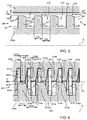
figure 1 is a side view, with a section along an axial longitudinal plane, of a rotating machine, in particular a gas turbine, according to an embodiment of the invention; -
figure 2 is an enlarged side view, with a partial section, of a detail of the rotating machine offigure 1 , where you can see a seal according to an embodiment of the invention; -
figure 3 is an enlarged side view, with a partial section, of the seal offigure 2 ; -
figure 4 is a side view, with a partial section, of a seal according to an alternative embodiment with respect to the embodiment offigure 3 ; -
figure 5 is a side view, with a partial section, of a seal according to another alternative embodiment with respect to the embodiment offigure 3 ; and -
figure 6 is an enlarged side view, with a partial section, of a seal according to another alternative embodiment with respect to the embodiment offigure 3 . -
Figure 1 shows, as a whole, arotating machine 1, in particular a gas turbine of a plant for the production of electrical energy. - The
rotating machine 1 comprises astator 2 and arotor 3. Therotating machine 1 extends along an axis A and has a compressor section 4 and an expansion orturbine section 5. Thestator 2 extends along the axis A in an annular manner. - The
rotor 3 is housed inside thestator 2, and is supported in a rotary manner by means of a front bearing assembly 7, which is arranged close to the compressor section 4, and of arear bearing assembly 8, which is arranged close to theturbine section 5. - The
turbine section 5 of therotor 3 is provided with a plurality ofrotor blades 10, which are arranged in groups that are axially spaced apart from one another so as to for a plurality of expansion stages. - With reference to
figure 2 , therotating machine 1 comprises aseal 6, which is arranged between therotor 3 and thestator 2 and is designed so as to reduce the passage of a flow F from a firsthigher pressure side 6a to a secondlower pressure side 6b. Theseal 6, in a preferred - though not limiting - embodiment of the invention, is a labyrinth seal. - Furthermore, the
rotor 3 comprises a plurality ofdisks 9, which are assembled with one another. Eachdisk 9 houses arespective rotor blade 10. Eachdisk 9 is shaped so as to have aportion 9a, in which therespective rotor blade 10 is fixed, and at least oneportion 9b, in which it is joined to anotherdisk 9. More in detail, all thedisks 9 of therotor 3, except the end disks, comprise twoportions 9b to be joined to tworespective disks 9 on opposite sides. Theseal 6 is arranged along theportions 9b of thedisks 9. In other words, theseal 6 is arranged along a circular surface of thedisk 9. - The
rotor 3 comprises acavity 11, which is defined between twodisks 9 and therespective rotor blades 10. Theseal 6 is arranged in thecavity 11. - With reference to
figures 1 and2 , thestator 2 comprises a plurality ofstator blades 12, which extend radially to the axis A towards therotor 3. Thestator blades 12 have anend 13 facing therotor 3 and adjacent thereto, which is at least partially housed in thecavity 11 between therotor blades 10. - The
seal 6 is arranged in theportions 9b of the tworotor disks 9 on one side, and in theend 13 of thestator 2 on the other side. - The
disks 9 of therotor 3 have different sizes and shapes depending on the portion of the compressor 4 or of theturbine 5 that they will occupy.Figure 2 only shows twodisks 9 of the plurality ofdisks 9. Infigure 1 you can see the plurality of disks making up therotor 3. - Furthermore, each
rotor blade 10 comprises aroot 14 and anairfoil 17. Theroot 14 is connected to therespective rotor disk 9 in theportion 9a of thedisk 9. - With reference to
figure 3 , theseal 6 extends along a direction of extension B from thehigher pressure side 6a to thelower pressure side 6b and comprises a rotatingportion 23a and astatic portion 23b. - The rotating
portion 23a is integral with therotor 3. More in detail, the rotatingportion 23a is connected to therotor 3 or is directly made on therotor 3. - The
static portion 23b is integral with thestator 2. More in detail, thestatic portion 23b is connected to thestator 2 or is directly made on thestator 2. - The
seal 6 comprises abase 24a; a row ofteeth 15a, which extends in length parallel to the direction of extension B and protrudes from thebase 24a radially to the direction B; abase 24b and a row ofteeth 15b, which extends in length parallel to the direction of extension B and protrudes from thebase 24b radially to the direction B. More in detail, the row ofteeth 15a and thebase 24a are comprised in therotating portion 23a of theseal 6. The row ofteeth 15b and thebase 24b are comprised in thestatic portion 23b of theseal 6. - Furthermore, the
seal 6 comprises aninterstice 25, which separates therotating portion 23a and thestatic portion 23b. - The
interstice 25 is also commonly called "gap" and is the space separating the rows ofteeth bases - The row of
teeth 15a is connected to thebase 24a and theteeth 15a of the row ofteeth 15a protrude towards thebase 24b. The row ofteeth 15b is connected to thebase 24b and theteeth 15b of the row ofteeth 15b protrude towards thebase 24a. Thebase 24a is housed on therotor 3. More in detail, thebase 24a is connected to therotor 3 or is part of therotor 3, in which case theteeth 15a are directly made on therotor 3 through a suitable processing, for example through a turning machining process. - The
base 24b is housed on thestator 2. More in detail, thebase 24b is connected to thestator 2 or is part of thestator 2, in which case theteeth 15b are directly made on thestator 2 through a suitable processing. - Each row of
teeth respective cavities adjacent teeth teeth teeth 15a of the row ofteeth 15a are distributed with a distribution pitch P1, which is constant. Theteeth 15b of the row ofteeth 15b are distributed with a distribution pitch P2, measured along the direction of extension B, which is constant. The distribution pitch P1 is different from the distribution pitch P2. In a preferred embodiment, the pitches P1 and P2 are measured along the direction of extension B. In another embodiment, which is not shown in the accompanying drawings, the pitches P1 and P2 are measured along the axis A. - The
seal 6 is an annular seal, which extends in length parallel to the direction of extension B and annularly around the axis A. Theteeth - With reference to
figures 2 and3 , the row ofteeth 15a is connected to therotor 3 through thebase 24a and the other row ofteeth 15b is connected to thestator 2 through thebase 24b. - Each
tooth respective surfaces respective surface respective surfaces respective surfaces respective bases surfaces - In a preferred - though not limiting - version of the invention, the
surfaces respective base surfaces - The
surfaces respective cavity respective surface surfaces respective cavity respective surface - In other words, the
surfaces respective surfaces respective surfaces side 6a to theside 6b. - In another preferred embodiment, which is not shown in the accompanying drawings, the
surfaces side 6a towards theside 6b, so as to deviate the incoming flow F towards therespective cavity - With reference to
figure 3 , theteeth edge higher pressure side 6a and anedge lower pressure side 6b. Theedges respective surfaces respective surfaces edges respective surfaces respective surfaces edges respective edge edges seal 6 is deviated towards therespective cavity respective edge edges - The
surfaces 10a and 20b have a respective height H1a and H1b, which is measured perpendicularly to the direction of extension B. Thesurfaces - The
surfaces surfaces - The ratio between a thickness D1a of the
tooth 15a and a width D2a of thecavity 16a is greater than 0.25. The thickness D1a of thetooth 15a is defined as the minimum distance between the twosurfaces tooth 15a. The width D2a of thecavity 16a is defined as the minimum distance between asurface 21a of one of theteeth 15a adjacent to thecavity 16a and thesurface 20a of theother tooth 15a adjacent to thecavity 16a. - The ratio between the thickness D1a of the
tooth 15a and the minimum height Hm of the interstice is greater than 0.3. - The ratio between a thickness D1b of the
tooth 15b and a width D2b of thecavity 16b is greater than 0.25. The thickness of thetooth 15b is defined as the minimum distance between the twosurfaces tooth 15b. The width of thecavity 16b is defined as the minimum distance between asurface 21b of one of theteeth 15b adjacent to thecavity 16b and thesurface 20b of theother tooth 15b adjacent to thecavity 16b. - The ratio between the thickness of the
tooth 15b and the minimum height Hm of the interstice is greater than 0.3. - The
teeth same seal 6 extend annularly and uniformly around the axis A; as a consequence, said ratios of theteeth same seal 6. - With reference to
figure 4 ,number 106 indicates an embodiment of a seal that is alternative to theseal 6. Theseal 106 comprises one single row ofteeth 115, which is connected to a base 124b of theseal 106 and faces a base of theseal 106 having asmooth surface 117. The row ofteeth 115 is connected to thestator 2 through thebase 124b. Thebase 124a is connected to therotor 3. In this case, aninterstice 125 is the space extending between the row ofteeth 115 and thesurface 117. - Each
tooth 115 has twosurfaces surfaces surfaces - The surface 122 has a profile, along the direction of extension B1, that is curved, in particular convex, so as to deviate the incoming flow F towards the
respective cavity 116 adjacent to thesurface 121. In other words, the surface 122 extends from an end of thesurface 120 to an end of thesurface 121 degrading from thehigher pressure side 6a to thelower pressure side 6b. - With reference to
figure 4 , theteeth 115 has anedge 118 facing thehigher pressure side 6a and anedge 119 facing thelower pressure side 6b. Theedge 118 defines a smaller angle compared to therespective edge 119. In other words, theedge 119 is rounded in such a way that part of the flow F leaking in theseal 106 is deviated towards thecavity 116 adjacent to theedge 119 thanks to the Coanda effect. - The
surfaces - The ratio between a thickness D11 of the
tooth 115 and a width D12 of thecavity 116 is greater than 0.25. The ratio between the thickness D11 of thetooth 115 and the minimum height H1m of theinterstice 125 is greater than 0.3. - The
teeth 115 of asame seal 106 extend annularly and uniformly around the axis A; as a consequence, said ratios of theteeth 115 are equal to one another for asame seal 106. - With reference to
figure 5 ,number 206 indicates an embodiment of a seal that is alternative to theseal 106. Theseal 206 comprises one single row ofteeth 215, which is connected to abase 224a of theseal 206 and faces a base 224b of theseal 206 having asmooth surface 217. The row ofteeth 215 is connected to therotor 3 through thebase 224a. The base is connected to thestator 2. In this case, theinterstice 225 is the space extending between the row ofteeth 215 and thesurface 217. - Each
tooth 215 has twosurfaces surface 222, which extends from an end of the twosurfaces surfaces - The
surface 222 has a profile, along the direction of extension B2, that is curved, in particular convex, so as to deviate the incoming flow F towards therespective cavity 216 adjacent to thesurface 221. In other words, thesurface 222 extends from an end of thesurface 220 to an end of thesurface 221 degrading from thehigher pressure side 6a to thelower pressure side 6b. - With reference to
figure 5 , theteeth 215 has anedge 218 facing thehigher pressure side 6a and anedge 219 facing thelower pressure side 6b. Theedge 218 defines a smaller angle compared to therespective edge 219. In other words, theedge 219 is rounded in such a way that part of the flow F leaking in theseal 206 is deviated towards thecavity 216 adjacent to theedge 219 thanks to the Coanda effect. - The
surfaces - The ratio between a thickness D21 of the
tooth 215 and a width D22 of thecavity 216 is greater than 0.25. The ratio between the thickness D21 of thetooth 215 and the minimum height H2m of theinterstice 225 is greater than 0.3. - The
teeth 215 of asame seal 206 extend annularly and uniformly around the axis A; as a consequence, said ratios of theteeth 215 are equal to one another for asame seal 206. - With reference to
figure 6 ,number 306 indicates an embodiment of a seal that is alternative to theseal 6. Thegasket 306 comprises two rows ofteeth respective side surfaces surfaces surfaces teeth respective base 324b 323 of theseal 306, so as to have a greater resistance to the force exerted by the flow F upon thetooth surfaces teeth 315a and 315, similarly to thesurfaces teeth respective base - Similarly to the
seal 6, theseal 306 comprisescavities adjacent teeth surfaces seal 306. In a non-limiting embodiment of the invention, thesurface 321a forms a first angle with thebase 324a, which is different from a second angle formed between thesurface 321b and thebase 324b. - In this embodiment and, in general, in those embodiments in which a thickness of the
teeth tooth surface tooth tooth - In this embodiment and, in general, in those embodiments in which a thickness D32a, D32b of the cavities 316a, 316b is not constant, the thickness D32a, D32b is calculated close to the free ends of the two respective
adjacent teeth cavity - Thanks to the invention, a greater part of a flow, compared to the prior art, is deviated towards the cavities, thus dissipating its kinetic energy and not leaking along the seal. In other words, thanks to the invention, the cavities receive a greater quantity of flow and, as a consequence, ensure better performances, as they better insulate the lower pressure side from the higher pressure side, hence limiting the flow flowing through the seal.
- It is evident that the seal and the rotating machine described above can be subjected to changes and variations, without for this reason going beyond the scope of protection of the invention, as set forth in the appended claims.
Claims (20)
- A seal for a rotating machine; the seal (6; 106; 206; 306) being configured to reduce the passage of a flow (F) from a first higher pressure side (6a) to a second lower pressure side (6b) and comprising at least one row of teeth (15a, 15b) extending from the first side (6a) to the second side (6b) along a direction of extension (B) of the seal (6); at least one cavity (16) arranged between respective two adjacent teeth (15a, 15b) of the row of teeth (15a, 15b); wherein at least one of the teeth (15a, 15b) has a first and a second surface (20a, 21a; 20a, 20b) which extend transversely to the direction of extension (B), and a third surface (22a, 22b) which extends between the first and the second surface (20a, 21a; 20a, 20b) and transversely thereto; wherein the third surface (22a, 22b) is shaped so as to divert the incoming flow (F) towards the cavity (16a, 16b) adjacent to the second surface (21a, 21b).
- The seal of claim 1, wherein the first surface (20a, 20b) faces the first higher pressure side (6a) and has a first height (H1a, H1b) measured perpendicular to the direction of extension (B); and the second surface (21a, 21b) is facing the second lower pressure side (6b) and has a second height (H2a, H2b) measured perpendicular to the direction of extension (B) being lesser than the first height (H1a, H1b).
- The seal of claim 1 or 2, wherein the third surface (22a, 22b) extends from one end of the first surface (20a, 20b) to one end of the second surface (21a, 21b) degrading along the direction from the first side (6a) to the second side (6b).
- The seal of any of the preceding claims, wherein the tooth (15a, 15b) has an edge (19a, 19b), preferably defined by the third surface (22a, 22b) and by the second surface (21a, 21b), being rounded or bevelled so that a part of the flow (F) is deviated towards the cavity (16a, 16b) adjacent to the second surface (21a, 21b) due to the Coanda effect.
- The seal of any of the preceding claims, wherein the third surface (22a, 22b) is curved, preferably convex with its convexity facing towards the second side (6b) at a lower pressure.
- The seal of any preceding claims, wherein the ratio between a thickness (D1a, D1b) of the tooth (15a, 15b) and a width (D2a, D2b) of the cavity (16a, 16b) is greater than 0.25, preferably said ratios between different teeth (15a, 15b) and cavities (16a, 16b) of said row of teeth (15a, 15b) are equal one to the other.
- The seal of any preceding claims, comprising a static part (24b), a rotating part (24a) and an interstice (25) separating the static part (24b) from the rotating part (24a); the ratio between a thickness (D1a) of the tooth (15a) and a minimum height (Hm) of the interstice (25) being greater than 0.3, preferably said ratios of the different teeth (15a, 15b) of said row of teeth (15a, 15b) being equal to each other.
- The seal of any of the preceding claims, wherein the seal (6) is an annular gasket extending around an axis (A) of extension of the rotating machine (1); and wherein the teeth (15a, 15b) extend annularly around the axis (A) and the third surface (22a, 22b) extends annularly in a uniform manner around the axis (A).
- The seal of any of the preceding claims, comprising another row of teeth (15b, 15a) comprising at least one cavity (16b, 16a) and facing the row of teeth (15b, 15a); preferably the interstice (25) extends between the row of teeth (15a, 15b) and the other row of teeth (15b, 15a).
- The seal according to claim 9, wherein the teeth (15a, 15b) of the row of teeth (15a, 15b) are distributed with a first distribution pitch (P1, P2); the other teeth (15b, 15a) of the other row of teeth (15b, 15a) are distributed with a second distribution pitch (P2, PI); and wherein the first distribution pitch (P1, P2) is different from the second distribution pitch (P2, P1).
- The seal of any one of the preceding claims, comprises a number of teeth (15a, 15b) greater than two; and wherein the teeth (15a, 15b) are distributed with a constant pitch along the direction of extension (B).
- The seal of any one of the preceding claims, comprises a number of teeth (15a, 15b) greater than two and wherein the teeth (15a, 15b) of said row of teeth (15a, 15b) have a first and a second surface (20a, 21a, 20b, 21b) extending transversely to the direction of extension (B), and a third surface (22a, 22b) extending between the first and the second surface (20, 21) and transversely thereto; wherein the first surface (20a, 20b) faces the first higher pressure side (6a) and the second surface (21a, 21b) faces the second lower pressure side (6b); and wherein preferably the third surface (22a, 22b) extends from one end of the first surface (20a, 20b) to one end of the second surface (21a, 21b) degrading along the direction of extension in a direction that goes from the first side (6a) to the second side (6b).
- The seal of any one of the preceding claims, wherein the seal (6) is labyrinth type.
- The seal of any one of the preceding claims, wherein the seal comprises a base (324a, 324b) from which the row of teeth (315a, 315b) protrudes; the second surface (321a, 321b) is inclined with respect to the base (324a, 324b), preferably towards the second lower pressure side (6b).
- A rotating machine (12) having a stator (2); a rotor (3) and which extends along an axis (A) ; and a seal (6; 106; 206; 306) arranged between the stator (2) and the rotor (3), and made according to any one of the preceding claims.
- The rotating machine of claim 15, wherein the row of teeth (15a, 15b) is connected to the rotor (3) or to the stator (2).
- The rotating machine of claim 15 or 16, wherein the rotor (3) is formed by at least two rotor disks (9), joined one to the other and the seal (6) is arranged on the circular surfaces of both disks (9).
- The rotating machine of one of claims 15 to 17, wherein the stator (2) comprises at least one stator blade (12) having one end (13), the seal (6; 106; 206; 306) comprises a static portion (23b) arranged on the end (13) of the stator blade (12), preferably said end (13) faces the rotor (3).
- The rotating machine having a stator (2); a rotor (3) and which extends along an axis (A); and a seal (6) arranged between the stator (2) and the rotor (3) of the rotating machine (1), and made according to claim 9 or 10, and wherein the row of teeth (15) is integral with the rotor (3) and the other row of teeth (15) is integral with the stator (2) or vice versa.
- The rotating machine of one of claims from 15 to 19, wherein the rotating machine (1) is a gas turbine comprising at least one turbine (5) and/or a compressor (4).
Applications Claiming Priority (1)
| Application Number | Priority Date | Filing Date | Title |
|---|---|---|---|
| ITUB2015A001927A ITUB20151927A1 (en) | 2015-07-03 | 2015-07-03 | SEALING GASKET AND ROTARY MACHINE INCLUDING THIS SEAL GASKET |
Publications (2)
| Publication Number | Publication Date |
|---|---|
| EP3112603A1 true EP3112603A1 (en) | 2017-01-04 |
| EP3112603B1 EP3112603B1 (en) | 2021-11-10 |
Family
ID=54288940
Family Applications (1)
| Application Number | Title | Priority Date | Filing Date |
|---|---|---|---|
| EP16177671.1A Active EP3112603B1 (en) | 2015-07-03 | 2016-07-02 | Labyrinth seal for a rotating machine, the seal using the coanda effect |
Country Status (4)
| Country | Link |
|---|---|
| EP (1) | EP3112603B1 (en) |
| KR (1) | KR20170004910A (en) |
| CN (1) | CN106321159A (en) |
| IT (1) | ITUB20151927A1 (en) |
Cited By (1)
| Publication number | Priority date | Publication date | Assignee | Title |
|---|---|---|---|---|
| US20240410287A1 (en) * | 2023-03-21 | 2024-12-12 | Raytheon Technologies Corporation | Integral composite stator labyrinth seal |
Citations (2)
| Publication number | Priority date | Publication date | Assignee | Title |
|---|---|---|---|---|
| US5890873A (en) * | 1997-08-13 | 1999-04-06 | General Electric Co. | Labyrinth seal for a turbine bucket cover |
| EP2354463A2 (en) * | 2009-12-31 | 2011-08-10 | General Electric Company | Turbine engine seals |
Family Cites Families (1)
| Publication number | Priority date | Publication date | Assignee | Title |
|---|---|---|---|---|
| CN204041127U (en) * | 2014-08-05 | 2014-12-24 | 三菱日立电力系统株式会社 | The seal arrangement of rotating machinery and gas turbine |
-
2015
- 2015-07-03 IT ITUB2015A001927A patent/ITUB20151927A1/en unknown
-
2016
- 2016-07-01 CN CN201610638248.XA patent/CN106321159A/en active Pending
- 2016-07-02 EP EP16177671.1A patent/EP3112603B1/en active Active
- 2016-07-04 KR KR1020160084294A patent/KR20170004910A/en not_active Withdrawn
Patent Citations (2)
| Publication number | Priority date | Publication date | Assignee | Title |
|---|---|---|---|---|
| US5890873A (en) * | 1997-08-13 | 1999-04-06 | General Electric Co. | Labyrinth seal for a turbine bucket cover |
| EP2354463A2 (en) * | 2009-12-31 | 2011-08-10 | General Electric Company | Turbine engine seals |
Cited By (1)
| Publication number | Priority date | Publication date | Assignee | Title |
|---|---|---|---|---|
| US20240410287A1 (en) * | 2023-03-21 | 2024-12-12 | Raytheon Technologies Corporation | Integral composite stator labyrinth seal |
Also Published As
| Publication number | Publication date |
|---|---|
| ITUB20151927A1 (en) | 2017-01-03 |
| CN106321159A (en) | 2017-01-11 |
| EP3112603B1 (en) | 2021-11-10 |
| KR20170004910A (en) | 2017-01-11 |
Similar Documents
| Publication | Publication Date | Title |
|---|---|---|
| US10443626B2 (en) | Non uniform vane spacing | |
| JP5575741B2 (en) | Casing for moving bladed wheel of turbomachine | |
| CN102378850B (en) | Axial turbomachine rotor having sealing disc | |
| US9822647B2 (en) | High chord bucket with dual part span shrouds and curved dovetail | |
| US10876411B2 (en) | Non-axisymmetric end wall contouring with forward mid-passage peak | |
| US8870535B2 (en) | Airfoil | |
| US10590774B2 (en) | Turbine bucket for control of wheelspace purge air | |
| BR112016013715B1 (en) | PART OR ASSEMBLY OF PARTS OF A TURBOMACHINE AND TURBOMACHINE | |
| US20140363279A1 (en) | Non-integral segmented angel-wing seal | |
| US20120093633A1 (en) | Turbomachine seal assembly | |
| US11156089B2 (en) | Steam turbine | |
| US9951648B2 (en) | Guide blade ring for an axial turbomachine and method for designing the guide blade ring | |
| US20200003060A1 (en) | Turbine element for high pressure drop and heat transfer | |
| CN106574505B (en) | For the controlled convergence compressor flow path of gas-turbine unit | |
| US9803495B2 (en) | Assembly | |
| EP3112603B1 (en) | Labyrinth seal for a rotating machine, the seal using the coanda effect | |
| CN106460528B (en) | Shield, movable vane body and rotating machinery | |
| CN102996258A (en) | Non-continuous ring seal | |
| JP6521273B2 (en) | Steam turbine | |
| US8545170B2 (en) | Turbo machine efficiency equalizer system | |
| KR102270498B1 (en) | Turbomachinery rotor and manufacturing method thereof | |
| JP5653486B2 (en) | Fixed vane assembly for axial turbines | |
| US20150003979A1 (en) | Steam turbine nozzle vane arrangement and method of manufacturing | |
| US20120321441A1 (en) | Ventilated compressor rotor for a turbine engine and a turbine engine incorporating same | |
| KR20190108637A (en) | How to deform a turbine |
Legal Events
| Date | Code | Title | Description |
|---|---|---|---|
| PUAI | Public reference made under article 153(3) epc to a published international application that has entered the european phase |
Free format text: ORIGINAL CODE: 0009012 |
|
| STAA | Information on the status of an ep patent application or granted ep patent |
Free format text: STATUS: THE APPLICATION HAS BEEN PUBLISHED |
|
| AK | Designated contracting states |
Kind code of ref document: A1 Designated state(s): AL AT BE BG CH CY CZ DE DK EE ES FI FR GB GR HR HU IE IS IT LI LT LU LV MC MK MT NL NO PL PT RO RS SE SI SK SM TR |
|
| AX | Request for extension of the european patent |
Extension state: BA ME |
|
| STAA | Information on the status of an ep patent application or granted ep patent |
Free format text: STATUS: REQUEST FOR EXAMINATION WAS MADE |
|
| 17P | Request for examination filed |
Effective date: 20170703 |
|
| RBV | Designated contracting states (corrected) |
Designated state(s): AL AT BE BG CH CY CZ DE DK EE ES FI FR GB GR HR HU IE IS IT LI LT LU LV MC MK MT NL NO PL PT RO RS SE SI SK SM TR |
|
| RAP1 | Party data changed (applicant data changed or rights of an application transferred) |
Owner name: ANSALDO ENERGIA S.P.A. |
|
| RIC1 | Information provided on ipc code assigned before grant |
Ipc: F01D 11/02 20060101ALI20210226BHEP Ipc: F01D 5/08 20060101ALN20210226BHEP Ipc: F01D 11/00 20060101AFI20210226BHEP |
|
| RIC1 | Information provided on ipc code assigned before grant |
Ipc: F01D 11/00 20060101AFI20210318BHEP Ipc: F01D 11/02 20060101ALI20210318BHEP Ipc: F01D 5/08 20060101ALN20210318BHEP |
|
| RIC1 | Information provided on ipc code assigned before grant |
Ipc: F01D 11/00 20060101AFI20210416BHEP Ipc: F01D 11/02 20060101ALI20210416BHEP Ipc: F01D 5/08 20060101ALN20210416BHEP |
|
| GRAP | Despatch of communication of intention to grant a patent |
Free format text: ORIGINAL CODE: EPIDOSNIGR1 |
|
| STAA | Information on the status of an ep patent application or granted ep patent |
Free format text: STATUS: GRANT OF PATENT IS INTENDED |
|
| INTG | Intention to grant announced |
Effective date: 20210604 |
|
| GRAS | Grant fee paid |
Free format text: ORIGINAL CODE: EPIDOSNIGR3 |
|
| GRAA | (expected) grant |
Free format text: ORIGINAL CODE: 0009210 |
|
| STAA | Information on the status of an ep patent application or granted ep patent |
Free format text: STATUS: THE PATENT HAS BEEN GRANTED |
|
| AK | Designated contracting states |
Kind code of ref document: B1 Designated state(s): AL AT BE BG CH CY CZ DE DK EE ES FI FR GB GR HR HU IE IS IT LI LT LU LV MC MK MT NL NO PL PT RO RS SE SI SK SM TR |
|
| REG | Reference to a national code |
Ref country code: GB Ref legal event code: FG4D |
|
| REG | Reference to a national code |
Ref country code: AT Ref legal event code: REF Ref document number: 1446294 Country of ref document: AT Kind code of ref document: T Effective date: 20211115 Ref country code: CH Ref legal event code: EP |
|
| REG | Reference to a national code |
Ref country code: DE Ref legal event code: R096 Ref document number: 602016065925 Country of ref document: DE |
|
| REG | Reference to a national code |
Ref country code: IE Ref legal event code: FG4D |
|
| REG | Reference to a national code |
Ref country code: LT Ref legal event code: MG9D |
|
| REG | Reference to a national code |
Ref country code: NL Ref legal event code: MP Effective date: 20211110 |
|
| REG | Reference to a national code |
Ref country code: AT Ref legal event code: MK05 Ref document number: 1446294 Country of ref document: AT Kind code of ref document: T Effective date: 20211110 |
|
| PG25 | Lapsed in a contracting state [announced via postgrant information from national office to epo] |
Ref country code: RS Free format text: LAPSE BECAUSE OF FAILURE TO SUBMIT A TRANSLATION OF THE DESCRIPTION OR TO PAY THE FEE WITHIN THE PRESCRIBED TIME-LIMIT Effective date: 20211110 Ref country code: LT Free format text: LAPSE BECAUSE OF FAILURE TO SUBMIT A TRANSLATION OF THE DESCRIPTION OR TO PAY THE FEE WITHIN THE PRESCRIBED TIME-LIMIT Effective date: 20211110 Ref country code: FI Free format text: LAPSE BECAUSE OF FAILURE TO SUBMIT A TRANSLATION OF THE DESCRIPTION OR TO PAY THE FEE WITHIN THE PRESCRIBED TIME-LIMIT Effective date: 20211110 Ref country code: BG Free format text: LAPSE BECAUSE OF FAILURE TO SUBMIT A TRANSLATION OF THE DESCRIPTION OR TO PAY THE FEE WITHIN THE PRESCRIBED TIME-LIMIT Effective date: 20220210 Ref country code: AT Free format text: LAPSE BECAUSE OF FAILURE TO SUBMIT A TRANSLATION OF THE DESCRIPTION OR TO PAY THE FEE WITHIN THE PRESCRIBED TIME-LIMIT Effective date: 20211110 |
|
| PG25 | Lapsed in a contracting state [announced via postgrant information from national office to epo] |
Ref country code: IS Free format text: LAPSE BECAUSE OF FAILURE TO SUBMIT A TRANSLATION OF THE DESCRIPTION OR TO PAY THE FEE WITHIN THE PRESCRIBED TIME-LIMIT Effective date: 20220310 Ref country code: SE Free format text: LAPSE BECAUSE OF FAILURE TO SUBMIT A TRANSLATION OF THE DESCRIPTION OR TO PAY THE FEE WITHIN THE PRESCRIBED TIME-LIMIT Effective date: 20211110 Ref country code: PT Free format text: LAPSE BECAUSE OF FAILURE TO SUBMIT A TRANSLATION OF THE DESCRIPTION OR TO PAY THE FEE WITHIN THE PRESCRIBED TIME-LIMIT Effective date: 20220310 Ref country code: PL Free format text: LAPSE BECAUSE OF FAILURE TO SUBMIT A TRANSLATION OF THE DESCRIPTION OR TO PAY THE FEE WITHIN THE PRESCRIBED TIME-LIMIT Effective date: 20211110 Ref country code: NO Free format text: LAPSE BECAUSE OF FAILURE TO SUBMIT A TRANSLATION OF THE DESCRIPTION OR TO PAY THE FEE WITHIN THE PRESCRIBED TIME-LIMIT Effective date: 20220210 Ref country code: NL Free format text: LAPSE BECAUSE OF FAILURE TO SUBMIT A TRANSLATION OF THE DESCRIPTION OR TO PAY THE FEE WITHIN THE PRESCRIBED TIME-LIMIT Effective date: 20211110 Ref country code: LV Free format text: LAPSE BECAUSE OF FAILURE TO SUBMIT A TRANSLATION OF THE DESCRIPTION OR TO PAY THE FEE WITHIN THE PRESCRIBED TIME-LIMIT Effective date: 20211110 Ref country code: HR Free format text: LAPSE BECAUSE OF FAILURE TO SUBMIT A TRANSLATION OF THE DESCRIPTION OR TO PAY THE FEE WITHIN THE PRESCRIBED TIME-LIMIT Effective date: 20211110 Ref country code: GR Free format text: LAPSE BECAUSE OF FAILURE TO SUBMIT A TRANSLATION OF THE DESCRIPTION OR TO PAY THE FEE WITHIN THE PRESCRIBED TIME-LIMIT Effective date: 20220211 Ref country code: ES Free format text: LAPSE BECAUSE OF FAILURE TO SUBMIT A TRANSLATION OF THE DESCRIPTION OR TO PAY THE FEE WITHIN THE PRESCRIBED TIME-LIMIT Effective date: 20211110 |
|
| PG25 | Lapsed in a contracting state [announced via postgrant information from national office to epo] |
Ref country code: SM Free format text: LAPSE BECAUSE OF FAILURE TO SUBMIT A TRANSLATION OF THE DESCRIPTION OR TO PAY THE FEE WITHIN THE PRESCRIBED TIME-LIMIT Effective date: 20211110 Ref country code: SK Free format text: LAPSE BECAUSE OF FAILURE TO SUBMIT A TRANSLATION OF THE DESCRIPTION OR TO PAY THE FEE WITHIN THE PRESCRIBED TIME-LIMIT Effective date: 20211110 Ref country code: RO Free format text: LAPSE BECAUSE OF FAILURE TO SUBMIT A TRANSLATION OF THE DESCRIPTION OR TO PAY THE FEE WITHIN THE PRESCRIBED TIME-LIMIT Effective date: 20211110 Ref country code: EE Free format text: LAPSE BECAUSE OF FAILURE TO SUBMIT A TRANSLATION OF THE DESCRIPTION OR TO PAY THE FEE WITHIN THE PRESCRIBED TIME-LIMIT Effective date: 20211110 Ref country code: DK Free format text: LAPSE BECAUSE OF FAILURE TO SUBMIT A TRANSLATION OF THE DESCRIPTION OR TO PAY THE FEE WITHIN THE PRESCRIBED TIME-LIMIT Effective date: 20211110 Ref country code: CZ Free format text: LAPSE BECAUSE OF FAILURE TO SUBMIT A TRANSLATION OF THE DESCRIPTION OR TO PAY THE FEE WITHIN THE PRESCRIBED TIME-LIMIT Effective date: 20211110 |
|
| REG | Reference to a national code |
Ref country code: DE Ref legal event code: R097 Ref document number: 602016065925 Country of ref document: DE |
|
| PLBE | No opposition filed within time limit |
Free format text: ORIGINAL CODE: 0009261 |
|
| STAA | Information on the status of an ep patent application or granted ep patent |
Free format text: STATUS: NO OPPOSITION FILED WITHIN TIME LIMIT |
|
| 26N | No opposition filed |
Effective date: 20220811 |
|
| PG25 | Lapsed in a contracting state [announced via postgrant information from national office to epo] |
Ref country code: AL Free format text: LAPSE BECAUSE OF FAILURE TO SUBMIT A TRANSLATION OF THE DESCRIPTION OR TO PAY THE FEE WITHIN THE PRESCRIBED TIME-LIMIT Effective date: 20211110 |
|
| PG25 | Lapsed in a contracting state [announced via postgrant information from national office to epo] |
Ref country code: SI Free format text: LAPSE BECAUSE OF FAILURE TO SUBMIT A TRANSLATION OF THE DESCRIPTION OR TO PAY THE FEE WITHIN THE PRESCRIBED TIME-LIMIT Effective date: 20211110 |
|
| PG25 | Lapsed in a contracting state [announced via postgrant information from national office to epo] |
Ref country code: MC Free format text: LAPSE BECAUSE OF FAILURE TO SUBMIT A TRANSLATION OF THE DESCRIPTION OR TO PAY THE FEE WITHIN THE PRESCRIBED TIME-LIMIT Effective date: 20211110 |
|
| REG | Reference to a national code |
Ref country code: CH Ref legal event code: PL |
|
| GBPC | Gb: european patent ceased through non-payment of renewal fee |
Effective date: 20220702 |
|
| REG | Reference to a national code |
Ref country code: BE Ref legal event code: MM Effective date: 20220731 |
|
| PG25 | Lapsed in a contracting state [announced via postgrant information from national office to epo] |
Ref country code: LU Free format text: LAPSE BECAUSE OF NON-PAYMENT OF DUE FEES Effective date: 20220702 Ref country code: LI Free format text: LAPSE BECAUSE OF NON-PAYMENT OF DUE FEES Effective date: 20220731 Ref country code: FR Free format text: LAPSE BECAUSE OF NON-PAYMENT OF DUE FEES Effective date: 20220731 Ref country code: CH Free format text: LAPSE BECAUSE OF NON-PAYMENT OF DUE FEES Effective date: 20220731 |
|
| PG25 | Lapsed in a contracting state [announced via postgrant information from national office to epo] |
Ref country code: IT Free format text: LAPSE BECAUSE OF FAILURE TO SUBMIT A TRANSLATION OF THE DESCRIPTION OR TO PAY THE FEE WITHIN THE PRESCRIBED TIME-LIMIT Effective date: 20211110 Ref country code: GB Free format text: LAPSE BECAUSE OF NON-PAYMENT OF DUE FEES Effective date: 20220702 Ref country code: BE Free format text: LAPSE BECAUSE OF NON-PAYMENT OF DUE FEES Effective date: 20220731 |
|
| PG25 | Lapsed in a contracting state [announced via postgrant information from national office to epo] |
Ref country code: IE Free format text: LAPSE BECAUSE OF NON-PAYMENT OF DUE FEES Effective date: 20220702 |
|
| PG25 | Lapsed in a contracting state [announced via postgrant information from national office to epo] |
Ref country code: HU Free format text: LAPSE BECAUSE OF FAILURE TO SUBMIT A TRANSLATION OF THE DESCRIPTION OR TO PAY THE FEE WITHIN THE PRESCRIBED TIME-LIMIT; INVALID AB INITIO Effective date: 20160702 |
|
| PG25 | Lapsed in a contracting state [announced via postgrant information from national office to epo] |
Ref country code: MK Free format text: LAPSE BECAUSE OF FAILURE TO SUBMIT A TRANSLATION OF THE DESCRIPTION OR TO PAY THE FEE WITHIN THE PRESCRIBED TIME-LIMIT Effective date: 20211110 Ref country code: CY Free format text: LAPSE BECAUSE OF FAILURE TO SUBMIT A TRANSLATION OF THE DESCRIPTION OR TO PAY THE FEE WITHIN THE PRESCRIBED TIME-LIMIT Effective date: 20211110 |
|
| P01 | Opt-out of the competence of the unified patent court (upc) registered |
Effective date: 20240430 |
|
| PG25 | Lapsed in a contracting state [announced via postgrant information from national office to epo] |
Ref country code: TR Free format text: LAPSE BECAUSE OF FAILURE TO SUBMIT A TRANSLATION OF THE DESCRIPTION OR TO PAY THE FEE WITHIN THE PRESCRIBED TIME-LIMIT Effective date: 20211110 |
|
| PG25 | Lapsed in a contracting state [announced via postgrant information from national office to epo] |
Ref country code: MT Free format text: LAPSE BECAUSE OF FAILURE TO SUBMIT A TRANSLATION OF THE DESCRIPTION OR TO PAY THE FEE WITHIN THE PRESCRIBED TIME-LIMIT Effective date: 20211110 |
|
| PGFP | Annual fee paid to national office [announced via postgrant information from national office to epo] |
Ref country code: DE Payment date: 20250722 Year of fee payment: 10 |