EP3112594A1 - Hot gas path component trailing edge having near wall cooling features - Google Patents
Hot gas path component trailing edge having near wall cooling features Download PDFInfo
- Publication number
- EP3112594A1 EP3112594A1 EP16174149.1A EP16174149A EP3112594A1 EP 3112594 A1 EP3112594 A1 EP 3112594A1 EP 16174149 A EP16174149 A EP 16174149A EP 3112594 A1 EP3112594 A1 EP 3112594A1
- Authority
- EP
- European Patent Office
- Prior art keywords
- hot gas
- cooling
- gas path
- path component
- micro
- Prior art date
- Legal status (The legal status is an assumption and is not a legal conclusion. Google has not performed a legal analysis and makes no representation as to the accuracy of the status listed.)
- Granted
Links
Images




Classifications
-
- F—MECHANICAL ENGINEERING; LIGHTING; HEATING; WEAPONS; BLASTING
- F01—MACHINES OR ENGINES IN GENERAL; ENGINE PLANTS IN GENERAL; STEAM ENGINES
- F01D—NON-POSITIVE DISPLACEMENT MACHINES OR ENGINES, e.g. STEAM TURBINES
- F01D5/00—Blades; Blade-carrying members; Heating, heat-insulating, cooling or antivibration means on the blades or the members
- F01D5/12—Blades
- F01D5/14—Form or construction
- F01D5/147—Construction, i.e. structural features, e.g. of weight-saving hollow blades
-
- F—MECHANICAL ENGINEERING; LIGHTING; HEATING; WEAPONS; BLASTING
- F01—MACHINES OR ENGINES IN GENERAL; ENGINE PLANTS IN GENERAL; STEAM ENGINES
- F01D—NON-POSITIVE DISPLACEMENT MACHINES OR ENGINES, e.g. STEAM TURBINES
- F01D25/00—Component parts, details, or accessories, not provided for in, or of interest apart from, other groups
- F01D25/08—Cooling; Heating; Heat-insulation
- F01D25/12—Cooling
-
- F—MECHANICAL ENGINEERING; LIGHTING; HEATING; WEAPONS; BLASTING
- F01—MACHINES OR ENGINES IN GENERAL; ENGINE PLANTS IN GENERAL; STEAM ENGINES
- F01D—NON-POSITIVE DISPLACEMENT MACHINES OR ENGINES, e.g. STEAM TURBINES
- F01D5/00—Blades; Blade-carrying members; Heating, heat-insulating, cooling or antivibration means on the blades or the members
- F01D5/12—Blades
- F01D5/14—Form or construction
- F01D5/18—Hollow blades, i.e. blades with cooling or heating channels or cavities; Heating, heat-insulating or cooling means on blades
- F01D5/186—Film cooling
-
- F—MECHANICAL ENGINEERING; LIGHTING; HEATING; WEAPONS; BLASTING
- F01—MACHINES OR ENGINES IN GENERAL; ENGINE PLANTS IN GENERAL; STEAM ENGINES
- F01D—NON-POSITIVE DISPLACEMENT MACHINES OR ENGINES, e.g. STEAM TURBINES
- F01D5/00—Blades; Blade-carrying members; Heating, heat-insulating, cooling or antivibration means on the blades or the members
- F01D5/12—Blades
- F01D5/14—Form or construction
- F01D5/18—Hollow blades, i.e. blades with cooling or heating channels or cavities; Heating, heat-insulating or cooling means on blades
- F01D5/187—Convection cooling
-
- F—MECHANICAL ENGINEERING; LIGHTING; HEATING; WEAPONS; BLASTING
- F01—MACHINES OR ENGINES IN GENERAL; ENGINE PLANTS IN GENERAL; STEAM ENGINES
- F01D—NON-POSITIVE DISPLACEMENT MACHINES OR ENGINES, e.g. STEAM TURBINES
- F01D9/00—Stators
- F01D9/02—Nozzles; Nozzle boxes; Stator blades; Guide conduits, e.g. individual nozzles
- F01D9/04—Nozzles; Nozzle boxes; Stator blades; Guide conduits, e.g. individual nozzles forming ring or sector
- F01D9/041—Nozzles; Nozzle boxes; Stator blades; Guide conduits, e.g. individual nozzles forming ring or sector using blades
-
- F—MECHANICAL ENGINEERING; LIGHTING; HEATING; WEAPONS; BLASTING
- F01—MACHINES OR ENGINES IN GENERAL; ENGINE PLANTS IN GENERAL; STEAM ENGINES
- F01D—NON-POSITIVE DISPLACEMENT MACHINES OR ENGINES, e.g. STEAM TURBINES
- F01D9/00—Stators
- F01D9/06—Fluid supply conduits to nozzles or the like
-
- F—MECHANICAL ENGINEERING; LIGHTING; HEATING; WEAPONS; BLASTING
- F01—MACHINES OR ENGINES IN GENERAL; ENGINE PLANTS IN GENERAL; STEAM ENGINES
- F01D—NON-POSITIVE DISPLACEMENT MACHINES OR ENGINES, e.g. STEAM TURBINES
- F01D5/00—Blades; Blade-carrying members; Heating, heat-insulating, cooling or antivibration means on the blades or the members
- F01D5/12—Blades
- F01D5/28—Selecting particular materials; Particular measures relating thereto; Measures against erosion or corrosion
- F01D5/288—Protective coatings for blades
-
- F—MECHANICAL ENGINEERING; LIGHTING; HEATING; WEAPONS; BLASTING
- F05—INDEXING SCHEMES RELATING TO ENGINES OR PUMPS IN VARIOUS SUBCLASSES OF CLASSES F01-F04
- F05D—INDEXING SCHEME FOR ASPECTS RELATING TO NON-POSITIVE-DISPLACEMENT MACHINES OR ENGINES, GAS-TURBINES OR JET-PROPULSION PLANTS
- F05D2220/00—Application
- F05D2220/30—Application in turbines
- F05D2220/32—Application in turbines in gas turbines
-
- F—MECHANICAL ENGINEERING; LIGHTING; HEATING; WEAPONS; BLASTING
- F05—INDEXING SCHEMES RELATING TO ENGINES OR PUMPS IN VARIOUS SUBCLASSES OF CLASSES F01-F04
- F05D—INDEXING SCHEME FOR ASPECTS RELATING TO NON-POSITIVE-DISPLACEMENT MACHINES OR ENGINES, GAS-TURBINES OR JET-PROPULSION PLANTS
- F05D2240/00—Components
- F05D2240/10—Stators
- F05D2240/12—Fluid guiding means, e.g. vanes
- F05D2240/122—Fluid guiding means, e.g. vanes related to the trailing edge of a stator vane
-
- F—MECHANICAL ENGINEERING; LIGHTING; HEATING; WEAPONS; BLASTING
- F05—INDEXING SCHEMES RELATING TO ENGINES OR PUMPS IN VARIOUS SUBCLASSES OF CLASSES F01-F04
- F05D—INDEXING SCHEME FOR ASPECTS RELATING TO NON-POSITIVE-DISPLACEMENT MACHINES OR ENGINES, GAS-TURBINES OR JET-PROPULSION PLANTS
- F05D2240/00—Components
- F05D2240/20—Rotors
- F05D2240/30—Characteristics of rotor blades, i.e. of any element transforming dynamic fluid energy to or from rotational energy and being attached to a rotor
- F05D2240/304—Characteristics of rotor blades, i.e. of any element transforming dynamic fluid energy to or from rotational energy and being attached to a rotor related to the trailing edge of a rotor blade
-
- F—MECHANICAL ENGINEERING; LIGHTING; HEATING; WEAPONS; BLASTING
- F05—INDEXING SCHEMES RELATING TO ENGINES OR PUMPS IN VARIOUS SUBCLASSES OF CLASSES F01-F04
- F05D—INDEXING SCHEME FOR ASPECTS RELATING TO NON-POSITIVE-DISPLACEMENT MACHINES OR ENGINES, GAS-TURBINES OR JET-PROPULSION PLANTS
- F05D2240/00—Components
- F05D2240/20—Rotors
- F05D2240/30—Characteristics of rotor blades, i.e. of any element transforming dynamic fluid energy to or from rotational energy and being attached to a rotor
- F05D2240/305—Characteristics of rotor blades, i.e. of any element transforming dynamic fluid energy to or from rotational energy and being attached to a rotor related to the pressure side of a rotor blade
-
- F—MECHANICAL ENGINEERING; LIGHTING; HEATING; WEAPONS; BLASTING
- F05—INDEXING SCHEMES RELATING TO ENGINES OR PUMPS IN VARIOUS SUBCLASSES OF CLASSES F01-F04
- F05D—INDEXING SCHEME FOR ASPECTS RELATING TO NON-POSITIVE-DISPLACEMENT MACHINES OR ENGINES, GAS-TURBINES OR JET-PROPULSION PLANTS
- F05D2240/00—Components
- F05D2240/20—Rotors
- F05D2240/30—Characteristics of rotor blades, i.e. of any element transforming dynamic fluid energy to or from rotational energy and being attached to a rotor
- F05D2240/306—Characteristics of rotor blades, i.e. of any element transforming dynamic fluid energy to or from rotational energy and being attached to a rotor related to the suction side of a rotor blade
-
- F—MECHANICAL ENGINEERING; LIGHTING; HEATING; WEAPONS; BLASTING
- F05—INDEXING SCHEMES RELATING TO ENGINES OR PUMPS IN VARIOUS SUBCLASSES OF CLASSES F01-F04
- F05D—INDEXING SCHEME FOR ASPECTS RELATING TO NON-POSITIVE-DISPLACEMENT MACHINES OR ENGINES, GAS-TURBINES OR JET-PROPULSION PLANTS
- F05D2260/00—Function
- F05D2260/20—Heat transfer, e.g. cooling
- F05D2260/202—Heat transfer, e.g. cooling by film cooling
-
- F—MECHANICAL ENGINEERING; LIGHTING; HEATING; WEAPONS; BLASTING
- F05—INDEXING SCHEMES RELATING TO ENGINES OR PUMPS IN VARIOUS SUBCLASSES OF CLASSES F01-F04
- F05D—INDEXING SCHEME FOR ASPECTS RELATING TO NON-POSITIVE-DISPLACEMENT MACHINES OR ENGINES, GAS-TURBINES OR JET-PROPULSION PLANTS
- F05D2260/00—Function
- F05D2260/20—Heat transfer, e.g. cooling
- F05D2260/204—Heat transfer, e.g. cooling by the use of microcircuits
-
- Y—GENERAL TAGGING OF NEW TECHNOLOGICAL DEVELOPMENTS; GENERAL TAGGING OF CROSS-SECTIONAL TECHNOLOGIES SPANNING OVER SEVERAL SECTIONS OF THE IPC; TECHNICAL SUBJECTS COVERED BY FORMER USPC CROSS-REFERENCE ART COLLECTIONS [XRACs] AND DIGESTS
- Y02—TECHNOLOGIES OR APPLICATIONS FOR MITIGATION OR ADAPTATION AGAINST CLIMATE CHANGE
- Y02T—CLIMATE CHANGE MITIGATION TECHNOLOGIES RELATED TO TRANSPORTATION
- Y02T50/00—Aeronautics or air transport
- Y02T50/60—Efficient propulsion technologies, e.g. for aircraft
Definitions
- the field of the present disclosure relates generally to turbine engines, and more particularly to hot gas path components having trailing edge near wall cooling.
- Gas turbine systems are widely utilized in fields such as power generation.
- a conventional gas turbine system includes a compressor, a combustor, and a turbine.
- various hot gas path components in the system are subjected to high temperature flows, which can cause the hot gas path components to fail. Since higher temperature flows generally result in increased performance, efficiency, and power output of the gas turbine system and are thus desired in a gas turbine system, the hot gas path components that are subjected to high temperature flows must be cooled to allow the gas turbine system to operate with flows at increased temperatures.
- airfoils of gas turbine buckets and nozzles often require complex cooling schemes in which air, typically bleed air, is forced through internal cooling passages within the airfoil, and then discharged through cooling holes or passages located at the airfoil surface, leading edge, and/or trailing edge to transfer heat from the hot gas path component.
- the hot gas path component cooling is achieved by locating impingement inserts within the component airfoil cavities, e.g., two or more cavities of a first stage nozzle of a gas turbine.
- the pressure and suction sides of the nozzle vane are impingement cooled.
- the post-impingement cooling air is then either discharged through film holes along the airfoil surface or sent to an additional circuit to convectively cool the airfoil trailing edge. Additional trailing edge circuits are often required due to insufficient space within the airfoil cavity to extend the aft impingement insert to the trailing edge.
- a hot gas path component in one aspect, includes a substrate including an outer surface and an inner surface.
- the inner surface defines a first interior space.
- the outer surface defines a pressure side surface and a suction side surface. The pressure and suction side surfaces are joined together at a leading edge and at a trailing edge of the hot gas path component.
- the substrate includes a trailing edge portion.
- the hot gas path component also includes a first cooling passage formed in the suction side surface of the trailing edge portion of the substrate and coupled in flow communication to the first interior space.
- the first cooling passage includes a first end and a second end.
- a second cooling passage separate from said first cooling passage, is formed in the pressure side surface of the trailing edge portion of the substrate.
- the second cooling passage is coupled in flow communication to the first interior space.
- the second cooling passage includes a first end and a second end.
- the component also includes a cover disposed over at least a portion of the first and second cooling passages.
- the first interior space channels a cooling fluid to the first and second cooling passages.
- the first and second cooling passages channel the cooling fluid therethrough to transfer heat away from the cover and the substrate.
- a gas turbine engine in another aspect, includes a compressor, a turbine coupled to the compressor, and a hot gas path component disposed in a least one of the compressor and the turbine.
- the hot gas path component includes a substrate including an outer surface and an inner surface. The inner surface defines a first interior space.
- the outer surface defines a pressure side surface and a suction side surface. The pressure and suction side surfaces are joined together at a leading edge and at a trailing edge of the hot gas path component.
- the substrate includes a trailing edge portion.
- the hot gas path component also includes a first cooling passage formed in the suction side surface of the trailing edge portion of the substrate and coupled in flow communication to the first interior space.
- the first cooling passage includes a first end and a second end.
- a second cooling passage separate from said first cooling passage, is formed in the pressure side surface of the trailing edge portion of the substrate.
- the second cooling passage is coupled in flow communication to the first interior space.
- the second cooling passage includes a first end and a second end.
- the component also includes a cover disposed over at least a portion of the first and second cooling passages.
- the first interior space channels a cooling fluid to the first and second cooling passages.
- the first and second cooling passages channel the cooling fluid therethrough to transfer heat away from the cover and the substrate.
- Approximating language may be applied to modify any quantitative representation that could permissibly vary without resulting in a change in the basic function to which it is related. Accordingly, a value modified by a term or terms, such as “about”, “approximately”, and “substantially”, are not to be limited to the precise value specified. In at least some instances, the approximating language may correspond to the precision of an instrument for measuring the value.
- range limitations may be combined and/or interchanged; such ranges are identified and include all the sub-ranges contained therein unless context or language indicates otherwise.
- FIG. 1 is a schematic view of a rotary machine, i.e., a turbomachine, and more specifically, a turbine engine.
- the turbine engine is a gas turbine engine 10.
- the rotary machine is any other turbine engine and/or rotary machine, including, without limitation, a steam turbine engine, a centrifugal compressor, and a turbocharger.
- gas turbine engine 10 includes at least one of each of a compressor 12, a combustor 14, a turbine 16, and a fuel nozzle 20.
- Fuel nozzle 20 is configured to inject and mix fuel (not shown) with pressurized air 24 in combustor 14.
- Turbine 16 includes one or more stators having fixed vanes or blades (not shown in FIG. 1 ), and one or more rotors having blades or buckets (not shown in FIG. 1 ) that rotate relative to the stators. Hot gas flow 22 passes over the turbine rotor blades, thereby driving the turbine rotor to rotate. Turbine 16 is coupled to a single rotatable shaft 18 such that it rotates the shaft as hot gas flow 22 passes over the turbine blades. In alternative embodiments, rotatable shaft 18 is a plurality of shaft segments coupled together to form rotatable shaft 18.
- rotatable shaft 18 is coupled to compressor 12.
- Compressor 12 includes blades (not shown) rigidly mounted to a rotor (not shown) that is driven to rotate by rotatable shaft 18. As air passes over the rotating blades, air pressure increases, thereby providing combustor 14 with sufficient pressurized air 24 for proper combustion.
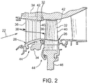
- FIG. 2 is a schematic view of a portion of turbine 16 of gas turbine engine 10 shown in FIG. 1 .
- turbine 16 includes a turbine blade 26 and a stator vane 28.
- turbine blade 26 and stator vane 28 each are referred to as a hot gas path component 38.
- a hot gas path component is any component of gas turbine engine 10 that is at least partially exposed to hot gas flow 22 through gas turbine engine 10, e.g., where the hot gas flow 22 operating temperature, in one example, is above 2500 degrees Fahrenheit (°F) ( ⁇ 1371 degrees Celsius (°C)).
- hot gas path component 38 includes, without limitation, turbine blade 26 and other bucket assemblies (also known as blades or blade assemblies), stator vane 28 and other nozzle assemblies (also known as vanes or vane assemblies), shroud assemblies, transition pieces, retaining rings, and compressor exhaust components.
- Hot gas path component 38 is not limited to the examples described above, but is any component that is at least partially exposed to hot gas flow 22.
- hot gas path component 38 is not limited to components of gas turbine engine 10, but may be any type of component that is exposed to high temperature flows. It should be understood that the description and figures that utilize a turbine, an airfoil, and a micro-channel are exemplary only. Additionally, it should be understood that the micro-channels described herein may be used in any suitable component through which a cooling fluid such as, water, steam, air, fuel and/or any other suitable fluid is directed for cooling the component and/or for maintaining a temperature of the component.
- a cooling fluid such as, water, steam, air, fuel and/or any other suitable fluid is directed for cooling the component and
- hot gas path component 38 When hot gas path component 38 is exposed to hot gas flow 22, hot gas path component 38 is heated by hot gas flow 22 and can reach a temperature at which hot gas path component 38 is substantially degraded or fails. Thus, in order to enable gas turbine engine 10 to operate with hot gas flow 22 at a high temperature, and increasing the efficiency, performance, and/or life of gas turbine engine 10, a cooling system 42 for hot gas path component 38 is required.
- micro-channel cooling facilitates significantly reducing the cooling requirements of hot gas path component 38 by placing the cooling features as close as possible to the heated region of hot gas path component 38, thus reducing the temperature difference between a hot side and a cold side of hot gas path component 38 for a given heat transfer rate.
- cooling system 42 includes a series of small passages, or micro-channels 30 (not shown in FIGS. 1-2 ), formed in the surface of hot gas path component 38.
- small or “micro” channel dimensions include a width and depth in the range between approximately 0.004 inches (in.)(0.10 millimeters (mm)) and approximately 0.100 in. (2.54 mm).
- a cooling fluid e.g., pressurized air 24, is provided to the micro-channels from a plenum, and the cooling fluid flows through each of the micro-channels, cooling hot gas path component 38.
- hot gas path components 38 each include an airfoil 32 having a leading edge 36 that is directly exposed to hot gas flow 22.
- airfoil 32 includes a trailing edge 40 axially opposite leading edge 36.
- Hot gas path component 38 is cooled by pressurized air 24 routed from one or more stages of compressor 12 through a casing 34 of gas turbine engine 10.
- pressurized air 24 is described as the cooling fluid used to cool the components 38 exposed to hot gas flow 22, e.g., turbine blade 26 and stator vane 28.
- a fluid other than pressurized air 24 may be used to cool components exposed to hot gas flow 22.
- cooling fluid includes any medium or material that flows, including, but not limited to gas, steam, and air.
- at least one cooling system 42 is defined in each hot gas path component 38 and is coupled in flow communication with a cooling fluid supply conduit 44 formed in casing 34.
- cooling fluid supply conduit 44 is fluidly connected to compressor 12.
- gas turbine engine 10 ingests air into compressor 12.
- Compressor 12 rotating at a high rotational speed compresses or pressurizes the air and channels a portion of pressurized air 24 to combustor 14 and a portion of pressurized air 24 to other areas of gas turbine engine 10 for use in cooling components 38 exposed to heat generated by gas turbine engine 10.
- Pressurized air 24 is mixed with fuel in combustor 14 and ignited to generate hot gas flow 22.
- Hot gas flow 22 is channeled from combustor 14 toward turbine 16 where hot gas flow 22 passes over hot gas path components 38, impacting turbine blade 26 connected to a rotor wheel 46.
- Rotor wheel 46 is rotated by hot gas flow 22 impacting turbine blade 26.
- Hot gas flow 22 also transfers heat to hot gas path components 38.
- a portion of pressurized air 24 is channeled through cooling system 42 formed in hot gas path components 38 to facilitate cooling the components.
- FIG. 3 is a schematic cross-section of a typical airfoil 32 of one of hot gas path components 38 of FIG. 2 , illustrating a portion of a cooling system 42 formed therein.
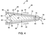
- FIG. 4 is an enlarged view of a trailing edge portion 64 of another typical airfoil 32 of one of hot gas path components 38 of FIG. 2 , illustrating a first embodiment of an arrangement for cooling trailing edge portion 64 of airfoil 32 with micro-channels 30 formed on both pressure side surface 58 and suction side surface 60 of airfoil 32.
- Cooling system 42 facilitates cooling hot gas path component 38 and enables gas turbine engine 10 to function with hot gas flow 22 at an increased temperature, which increases the efficiency and performance of gas turbine engine 10.
- hot gas path component 38 includes a substrate 48 having an outer surface 50 and an inner surface 52. As shown, for example in FIGS. 3 and 4 , inner surface 52 defines at least one hollow, interior space or plenum 54. Outer surface 50 of substrate 48 defines a concave pressure side surface 58 and a convex suction side surface 60 where the pressure and suction side surfaces 58, 60 are joined together at leading edge 36 and at trailing edge 40 of hot gas path component 38.
- hot gas path component 38 is formed by a casting process such as, but not limited to, an investment casting process, and is fabricated from any suitable material depending on the intended application for hot gas path component 38.
- hot gas path component 38 can be formed from Ni-base, Co-base, and Fe-base superalloys and the like. Some Ni-base superalloys are known to be advantageous because of a combination of desirable properties including high temperature strength and high temperature creep resistance.
- the material used to form substrate 48 may also include a NiAl intermetallic alloy, as these alloys are also known to possess a combination of superior properties including high temperature strength and high temperature creep resistance that are advantageous for use in turbine engine applications used for aircraft.
- substrate 48 is formed from any material that enables substrate 48 to function as described herein.
- cooling system 42 includes a series of small passages, or micro-channels 30, formed in substrate 48 of hot gas path component 38.
- micro-channels 30 are formed in outer surface 50 of substrate 48 by either a casting process or by a casting process and a finish machining process.
- micro-channels 30 may be formed using a variety of techniques.
- techniques for forming micro-channels 30 include laser machining, water jet machining, electro-chemical machining (ECM), electro-discharge machining (EDM), photolithography, or any other process capable of providing micro-channels with proper sizes and tolerances.
- EDM electro-chemical machining
- EDM electro-discharge machining
- photolithography or any other process capable of providing micro-channels with proper sizes and tolerances.
- the EDM process can include a multi-axis computer numerically controlled (CNC) unit.
- micro-channels 30 can extend between a first end and a second end in any lengthwise configuration, for example, without limitation, straight, curved, or having multiple curves.
- micro-channels 30 can be finished machined into outer surface 50 of substrate 48.
- One or more inlet passages 62 connecting micro-channels 30 to plenum 54 are drilled using, for example, without limitation, electro-discharge machining (EDM) or any conventional drilling method that enables inlet passages 62 to be formed as described herein.
- EDM electro-discharge machining
- micro-channels 30, inlet passages 62, and at least a portion of plenum 54, as described herein is 3D printed using direct metal laser melting (DMLM) processing.
- DMLM direct metal laser melting
- a trailing edge portion 64 of airfoil 32 is formed by machined pieces that are joined via brazing or diffusion bonding and this trailing edge portion 64 is then joined to airfoil 32.
- the "trailing edge portion 64" means being within about thirty percent of the surface length of substrate 48 from trailing edge 40, as measured on either side of substrate 48 between leading edge 36 and trailing edge 40.
- hot gas path component 38 includes one or more recesses 56 formed in outer surface 50 of hot gas path component 38.
- Micro-channels 30 are formed in a bottom surface 66 of each of recesses 56 and are covered by a braze sheet or pre-sintered preform (PSP) 68.
- Recesses 56 are offset from the outer surfaces of hot gas path component 38 a predefined, substantially uniform distance such that bottom surface 66 of recesses 56 conforms to the shape of outer surface 50 of hot gas path component 38.
- a recess 56 formed in convex suction side surface 60 of airfoil 32 conforms to the airfoil surface shape and is offset a predefined distance substantially equal to a thickness of braze sheet 68.
- recess 56 is an open sided recess, i.e., recess 56 includes at least one recess edge 80 bounding recess 56.
- micro-channels 30, formed in airfoil 32 extend substantially axially, i.e., generally parallel with hot gas flow 22.
- micro-channels 30 can be disposed at any relative locations and extend in any direction that enables cooling system 42 to function as described herein, for example, without limitation, micro-channels 30 may comprise a serpentine configuration.
- inlet passages 62 may be individually coupled in flow communication to airfoil 32 or may be coupled in flow communication to a common trough or plenum 54.
- An outlet passage 78 may couple the exhaust ends of micro-channels 30 together to exhaust pressurized air 24 through trailing edge 40 of hot gas path component 38, or may be coupled in flow communication to a common trough or end plenum 70 (not shown in FIG. 4 ).
- hot gas path component 38 includes a coating 72 formed over at least a portion of outer surface 50 and braze sheets 68, forming a protective material layer on hot gas path component 38.
- coating 72 includes at least two material layers, for example, a bond coat 74 and a thermal barrier coating (TBC) 76.
- Bond coat 74 is any appropriate bonding material.
- bond coat 74 has a chemical composition MCrAl(X), where "M" is an element selected from the group consisting of Fe, Co, Ni, and various combinations thereof.
- Bond coat 74 may be applied to substrate 48 and braze sheets 68 by a variety of processes described further herein, for example, by an ion plasma deposition process or a thermal spray process.
- bond coat 74 may be a diffusion aluminide bond coat, such as a coating having the chemical composition NiAl or PtAl, and bond coat 74 may be applied to the substrate 48 and braze sheets 68 through, for example, vapor phase aluminiding or chemical vapor deposition.
- TBC 76 is any appropriate thermal barrier material.
- TBC 76 is a yttria-stabilized zirconia and may be applied to hot gas path component 38 through a physical vapor deposition process or thermal spray process as described herein.
- TBC 76 may be a ceramic, for example, without limitation, a thin layer of zirconia modified by other refractory oxides such as oxides formed from Group IV, V and VI elements or oxides modified by Lanthanide series elements such as La, Nd, Gd, Yb, and the like.
- coating 72 has a thickness in the range of 0.1 to 2.0 millimeters, and more particularly, in the range of 0.1 to 1 millimeter, and still more particularly 0.1 to 0.5 millimeters for industrial gas turbine components.
- hot gas path component 38 can be formed from a high temperature ceramic matrix composite (CMC) and coating 72 can include an environmental barrier coating (EBC) system that includes one or more material layers.
- CMC high temperature ceramic matrix composite
- EBC environmental barrier coating
- the layers of coating 72 are deposited onto hot gas path component 38 using a variety of techniques.
- coating 72 is disposed over at least a portion of outer surface 50 of substrate 48 by performing an ion plasma deposition.
- ion plasma deposition includes placing a cathode formed of a coating material into a vacuum environment within a vacuum chamber, providing substrate 48 within the vacuum environment, supplying a current to the cathode to form a cathodic arc upon a cathode surface resulting in erosion or evaporation of coating material from the cathode surface, and depositing the coating material from the cathode upon the substrate outer surface 50.
- the ion plasma deposition process includes a plasma vapor deposition process.
- Nonlimiting examples of coating 72 include structural coatings, bond coatings, oxidation-resistant coatings, and thermal barrier coatings.
- coating 72 is disposed over at least a portion of outer surface 50 of substrate 48 by performing a thermal spray process.
- the thermal spray process includes combustion spraying and/or plasma spraying.
- the combustion spraying process includes high velocity oxygen fuel spraying (HVOF) or high velocity air fuel spraying (HVAF).
- the plasma spraying process includes atmospheric (such as air or inert gas) plasma spray or low pressure plasma spray (LPPS), which is also known as vacuum plasma spray (VPS).
- techniques for depositing one or more layers of coating 72 include, without limitation, sputtering, electron beam physical vapor deposition, electroless plating, electroplating, and any other process that enables coating 72 to function as described herein.
- FIG. 5 is an enlarged view of trailing edge portion 64 of another typical airfoil 32 of one of hot gas path components 38 of FIG. 2 , illustrating a second embodiment of an arrangement for cooling trailing edge portion 64 of airfoil 32 with micro-channels 30 formed on both pressure side surface 58 and suction side surface 60 of airfoil 32.
- hot gas path component 38 includes one or more recesses 56 formed in outer surface 50 of hot gas path component 38.
- Cooling system 42 includes a series of micro-channels 30 formed in bottom surface 66 of each of recesses 56 and covered by braze sheet 68.
- micro-channels 30 are formed by either a casting process or by a casting process and a finish machining process.
- micro-channels 30 may be formed using a variety of techniques, including, without limitation, laser machining, water jet machining, ECM processes, EDM processes, photolithography, or any other process capable of providing micro-channels with proper sizes and tolerances.
- micro-channels 30 can have any lengthwise configuration, for example, without limitation, straight, curved, or having multiple curves. After casting hot gas path component 38, micro-channels 30 can be finished machined.
- One or more inlet passages 62 are formed to connect micro-channels 30 to plenum 54.
- recesses 56 are offset from outer surface 50 of hot gas path component 38 a predefined, substantially uniform distance such that bottom surface 66 of recess 56 conforms to the shape of outer surface 50.
- a recess 56 formed in convex suction side surface 60 of airfoil 32 conforms to the airfoil surface shape and is offset a predefined distance substantially equal to a thickness of braze sheet 68.
- the original airfoil shape and surface location is established by the application of braze sheet 68 to recess 56.
- recess 56 is an open sided recess, i.e., recess 56 includes recess edge 80 bounding recess 56 at trailing edge 40. At least one edge of braze sheet 68 abuts recess edge 80.
- micro-channels 30 extend substantially axially, i.e., generally parallel with hot gas flow 22.
- micro-channels 30 can be disposed at any relative locations and extend in any direction that enables cooling system 42 to function as described herein, for example, without limitation, micro-channels 30 may comprise a serpentine configuration.
- inlet passages 62 may be individually coupled in flow communication to plenum 54.
- Hot gas path component 38 includes one or more film cooling holes or outlet passages 78 formed in flow communication with micro-channels 30 to exhaust pressurized air 24 through at least one of side surfaces 58, 60 along trailing edge portion 64.
- Outlet passages 78 may be any shaped passage or hole that enables outlet passages 78 to function as described herein.
- micro-channel 30 includes a single outlet passage 78 positioned generally at an end of micro-channel 30.
- micro-channel 30 includes more than one outlet passage 78 spaced apart along a length of micro-channel 30, thus forming a trench exit micro-channel. It is contemplated that each discrete micro-channel 30 can include any number of film cooling holes or outlet passages 78 that enable cooling system 42 to function as described herein.
- hot gas path component 38 includes coating 72 formed over at least a portion of outer surface 50 and braze sheets 68.
- coating 72 includes at least two material layers, for example, a bond coat 74 and a thermal barrier coating (TBC) 76.
- Bond coat 74 is any appropriate bonding material described herein
- TBC 76 is any appropriate thermal barrier material described herein.
- hot gas path component 38 can be formed from a high temperature ceramic matrix composite (CMC) and coating 72 can include an environmental barrier coating (EBC) system that includes one or more material layers.
- FIG. 6 is an enlarged view of trailing edge portion 64 of another typical airfoil 32 of one of hot gas path components 38 of FIG.
- cooling system 42 of hot gas path component 38 includes a series of micro-channels 30 formed in outer surface 50 of airfoil 32 and covered by braze sheets 68.
- micro-channels 30 are formed by either a casting process or by a casting process and a finish machining process.
- micro-channels 30 may be formed using a variety of techniques, including, without limitation, laser machining, water jet machining, ECM processes, EDM processes, photolithography, or any other process capable of providing micro-channels with proper sizes and tolerances.
- micro-channels 30 can have any lengthwise configuration, for example, without limitation, straight, curved, or having multiple curves. After casting hot gas path component 38, micro-channels 30 can be finished machined. One or more inlet passages 62 are formed to connect micro-channels 30 to plenum 54.
- braze sheets 68 are coupled to outer surface 50 of hot gas path component 38 and conform to the shape of outer surface 50.
- a braze sheet 68 coupled to convex suction side surface 60 of airfoil 32 conforms to the airfoil surface shape so as to maintain the proper airfoil design.
- the original airfoil shape and outer surface location is established by the application of braze sheet 68 to airfoil 32.
- micro-channels 30 extend substantially axially, i.e., generally parallel with hot gas flow 22.
- micro-channels 30 can be disposed at any relative locations and extend in any direction that enables cooling system 42 to function as described herein, for example, without limitation, micro-channels 30 may comprise a serpentine configuration.
- inlet passages 62 may be individually coupled in flow communication to plenum 54.
- Hot gas path component 38 includes an outlet passage 78 at trailing edge 40 formed in flow communication with each micro-channel 30, respectively, to exhaust pressurized air 24 at the trailing edge 40 of airfoil 32.
- Outlet passage 78 may be any shaped passage or hole that enables outlet passage 78 to function as described herein.
- micro-channel 30 includes a single outlet passage 78 positioned generally in line and at an end of each micro-channel 30. It is contemplated that each discrete micro-channel 30 can include more than one outlet passage 78, for example, spaced along micro-channel 30 to exhaust pressurized air 24 through at least one of side surfaces 58, 60, to enable cooling system 42 to function as described herein.
- hot gas path component 38 includes coating 72 formed over at least a portion of outer surface 50 and braze sheets 68.
- coating 72 includes at least two material layers, for example, a bond coat 74 and a thermal barrier coating (TBC) 76.
- Bond coat 74 is any appropriate bonding material described herein
- TBC 76 is any appropriate thermal barrier material described herein.
- hot gas path component 38 can be formed from a high temperature ceramic matrix composite (CMC) and coating 72 can include an environmental barrier coating (EBC) system that includes one or more material layers.
- CMC high temperature ceramic matrix composite
- EBC environmental barrier coating
- FIG. 7 is an enlarged view of trailing edge portion 64 of another typical airfoil 32 of one of hot gas path components 38 of FIG. 2 , illustrating a fourth embodiment of an arrangement for cooling trailing edge portion 64 of airfoil 32 with micro-channels 30 formed on both pressure side surface 58 and suction side surface 60 of airfoil 32.
- hot gas path component 38 includes one or more recesses 56 formed in outer surface 50 of hot gas path component 38.
- Cooling system 42 includes a series of micro-channels 30 formed in bottom surface 66 of each of recesses 56 and covered by braze sheet 68.
- micro-channels 30 are formed by either a casting process or by a casting process and a finish machining process.
- micro-channels 30 may be formed using a variety of techniques, including, without limitation, laser machining, water jet machining, ECM processes, EDM processes, photolithography, or any other process capable of providing micro-channels with proper sizes and tolerances.
- micro-channels 30 can have any lengthwise configuration, for example, without limitation, straight, curved, or having multiple curves. After casting hot gas path component 38, micro-channels 30 can be finished machined.
- One or more inlet passages 62 are formed to connect micro-channels 30 to plenum 54.
- recesses 56 are offset from outer surface 50 of hot gas path component 38 a predefined, substantially uniform distance such that bottom surface 66 of recess 56 conforms to the shape of outer surface 50.
- a recess 56 formed in convex suction side surface 60 of airfoil 32 conforms to the airfoil surface shape and is offset a predefined distance substantially equal to a thickness of braze sheet 68.
- the original airfoil shape and surface location is established by the application of braze sheet 68 to recess 56.
- recess 56 is an open sided recess, i.e., recess 56 includes recess edge 80 bounding recess 56 at trailing edge 40.
- micro-channels 30 extend substantially axially, i.e., generally parallel with hot gas flow 22.
- micro-channels 30 can be disposed at any relative locations and extend in any direction that enables cooling system 42 to function as described herein, for example, without limitation, micro-channels 30 may comprise a serpentine configuration.
- inlet passages 62 may be individually coupled in flow communication to plenum 54.
- Outlet passage 78 is coupled in flow communication to micro-channels 30 and a common outlet trough or outlet plenum 82 to exhaust pressurized air 24 proximate trailing edge 40 of hot gas path component 38.
- outlet plenum 82 is located upstream from trailing edge 40 and is configured to exhaust pressurized air 24 through one or more outlet passages or film cooling holes (not shown) that are located out of plane with micro-channels 30 shown in FIG. 7 and extend through at least one of side surfaces 58, 60 along trailing edge portion 64.
- hot gas path component 38 includes coating 72 formed over at least a portion of outer surface 50 and braze sheets 68.
- coating 72 includes at least two material layers, for example, a bond coat 74 and a thermal barrier coating (TBC) 76.
- Bond coat 74 is any appropriate bonding material described herein
- TBC 76 is any appropriate thermal barrier material described herein.
- hot gas path component 38 can be formed from a high temperature ceramic matrix composite (CMC) and coating 72 can include an environmental barrier coating (EBC) system that includes one or more material layers.
- CMC high temperature ceramic matrix composite
- EBC environmental barrier coating
- FIG. 8 is an enlarged view of trailing edge portion 64 of another typical airfoil 32 of one of hot gas path components 38 of FIG. 2 , illustrating a fifth embodiment of an arrangement for cooling trailing edge portion 64 of airfoil 32 with micro-channels 30 formed on both pressure side surface 58 and suction side surface 60 of airfoil 32.
- hot gas path component 38 includes one or more recesses 56 formed in outer surface 50 of hot gas path component 38.
- Cooling system 42 includes a series of micro-channels 30 formed in bottom surface 66 of each of recesses 56 and covered by braze sheet 68.
- micro-channels 30 are formed by either a casting process or by a casting process and a finish machining process.
- micro-channels 30 may be formed using a variety of techniques, including, without limitation, laser machining, water jet machining, ECM processes, EDM processes, photolithography, or any other process capable of providing micro-channels with proper sizes and tolerances.
- micro-channels 30 can have any lengthwise configuration, for example, without limitation, straight, curved, or having multiple curves. After casting hot gas path component 38, micro-channels 30 can be finished machined.
- recesses 56 are offset from outer surface 50 of hot gas path component 38 a predefined, substantially uniform distance such that bottom surface 66 of recess 56 conforms to the shape of outer surface 50.
- a recess 56 formed in convex suction side surface 60 of airfoil 32 conforms to the airfoil surface shape and is offset a predefined distance substantially equal to a thickness of braze sheet 68.
- the original airfoil shape and surface location is established by the application of braze sheet 68 to recess 56.
- recess 56 is an open sided recess, i.e., recess 56 includes recess edge 80 bounding recess 56 at trailing edge 40.
- inlet passage 62 is formed substantially axially to connect micro-channels 30 to plenum 54.
- inlet passage 62 extends aftward from plenum 54 and is coupled in flow communication with one or more micro-channels 30 at trailing edge 40.
- pressurized air 24 flows through plenum 54, it is exhausted afterward through inlet passage 62.
- Pressurized air 24 travels aftward toward micro-channels 30 where it makes a sharp turn forward, traveling through each of micro-channels 30.
- micro-channels 30 extend substantially axially, i.e., generally parallel with hot gas flow 22.
- micro-channels 30 can be disposed at any relative locations and extend in any direction that enables cooling system 42 to function as described herein, for example, without limitation, micro-channels 30 may comprise a serpentine configuration.
- hot gas path component 38 includes one or more film cooling holes or outlet passages 78 formed in flow communication with micro-channels 30 to exhaust pressurized air 24 through at least one of side surfaces 58, 60 along trailing edge portion 64.
- Outlet passages 78 may be any shaped passage or hole that enables outlet passages 78 to function as described herein.
- micro-channel 30 includes a single outlet passage 78 positioned generally at the anterior end of micro-channels 30.
- micro-channel 30 includes one outlet passage 78.
- micro-channels 30 include more than one outlet passage 78 spaced apart along a length of micro-channel 30, thus forming a trench exit micro-channel. It is contemplated that each discrete micro-channel 30 can include any number of film cooling holes or outlet passages 78 that enable cooling system 42 to function as described herein.
- hot gas path component 38 includes coating 72 formed over at least a portion of outer surface 50 and braze sheets 68.
- coating 72 includes at least two material layers, for example, a bond coat 74 and a thermal barrier coating (TBC) 76.
- Bond coat 74 is any appropriate bonding material described herein
- TBC 76 is any appropriate thermal barrier material described herein.
- hot gas path component 38 can be formed from a high temperature ceramic matrix composite (CMC) and coating 72 can include an environmental barrier coating (EBC) system that includes one or more material layers.
- FIG. 9 is an enlarged view of trailing edge portion 64 of another typical airfoil 32 of one of hot gas path components 38 of FIG.
- cooling system 42 of hot gas path component 38 includes a series of micro-channels 30 formed in outer surface 50 of airfoil 32 and covered by braze sheets 68.
- micro-channels 30 are formed by either a casting process or by a casting process and a finish machining process.
- micro-channels 30 may be formed using a variety of techniques, including, without limitation, laser machining, water jet machining, ECM processes, EDM processes, photolithography, or any other process capable of providing micro-channels with proper sizes and tolerances.
- micro-channels 30 can have any lengthwise configuration, for example, without limitation, straight, curved, or having multiple curves. After casting hot gas path component 38, micro-channels 30 can be finished machined. One or more inlet passages 62 are formed to connect micro-channels 30 to plenum 54.
- braze sheets 68 are coupled to outer surface 50 of hot gas path component 38 and conform to the shape of outer surface 50.
- a braze sheet 68 coupled to convex suction side surface 60 of airfoil 32 conforms to the airfoil surface shape so as to maintain the proper airfoil design.
- the original airfoil shape and outer surface location is established by the application of braze sheet 68 to airfoil 32.
- micro-channels 30 extend substantially axially, i.e., generally parallel with hot gas flow 22.
- micro-channels 30 can be disposed at any relative locations and extend in any direction that enables cooling system 42 to function as described herein, for example, without limitation, micro-channels 30 may comprise a serpentine configuration.
- inlet passages 62 may be individually coupled in flow communication to plenum 54.
- hot gas path component 38 includes outlet passage 78 at trailing edge 40 formed in flow communication with one of micro-channels 30 to exhaust pressurized air 24 to one side of trailing edge 40 of airfoil 32.
- Outlet passage 78 may be any shaped passage or hole that enables outlet passage 78 to function as described herein.
- Outlet passage 78 is positioned generally in line and at an aft end of each micro-channel 30.
- the opposite side micro-channel 30 is a closed micro-channel, i.e., it has not outlet passage 78. As shown, the closed micro-channel 30 can end before reaching trailing edge 40, enabling the opposite side micro-channel 30 to provide cooling to both sides of the trailing edge of airfoil 32.
- a cross flow passage 84 is coupled between each of micro-channels 30 at trailing edge 40 to enable pressurized air 24 to flow through each of micro-channels 30 and exit through the single outlet passage 78.
- hot gas path component 38 includes a film cooling hole 86 coupled in flow communication to the closed micro-channel 30.
- hot gas path component 38 includes coating 72 formed over at least a portion of outer surface 50 and braze sheets 68.
- coating 72 includes at least two material layers, for example, a bond coat 74 and a thermal barrier coating (TBC) 76.
- Bond coat 74 is any appropriate bonding material described herein
- TBC 76 is any appropriate thermal barrier material described herein.
- hot gas path component 38 can be formed from a high temperature ceramic matrix composite (CMC) and coating 72 can include an environmental barrier coating (EBC) system that includes one or more material layers.
- CMC high temperature ceramic matrix composite
- EBC environmental barrier coating
- pressurized air 24 flows through cooling system 42, and in particular, plenum 54, at a pressure generally higher than a pressure in inlet passage 62 and micro-channel 30.
- the pressure differential causes a portion of pressurized air 24 contained within cooling system 42 to flow into and through inlet passage 62, and from inlet passage 62 into and through micro-channel 30.
- Inlet passage 62 is configured to provide convection cooling to coating 72.
- inlet passage 62 is oriented at an angle to braze sheet 68, which enables pressurized air 24 to impact on braze sheet 68 with a relatively high velocity, thus increasing the cooling effectiveness of pressurized air 24.
- pressurized air 24 flows through inlet passage 62 and is provided to micro-channel 30, pressurized air 24 impacts on braze sheet 68, providing convection cooling of coating 72.
- pressurized air 24 may be exhausted from micro-channels 30 through outlet passage 78.
- pressurized air 24 is exhausted off of trailing edge 40 of airfoil 32 and into the path of hot gas flow 22.
- outlet passage 78 can be any shaped hole or passage that enables cooling system 42 to function as described herein.
- the systems and methods described herein facilitate cooling the trailing edge portion 64 of a hot gas path component 38 at a high heat transfer rate and with a relatively uniform temperature profile by use of near wall cooling micro-channels 30.
- the geometry of micro-channels 30 enabler improved cooling efficiency of trailing edge portion 64.
- the fabrication of micro-channels 30 and braze sheet 68 facilitate increasing the density and reducing the size of micro-channels 30 to optimize heat transfer efficiency.
- Cooling system 42 facilitates increasing the life of hot gas path component 38 and enabling hot gas path component 38 to be utilized with higher temperature hot gas flows 22, thus increasing the performance and efficiency of gas turbine engine 10.
Landscapes
- Engineering & Computer Science (AREA)
- Mechanical Engineering (AREA)
- General Engineering & Computer Science (AREA)
- Architecture (AREA)
- Turbine Rotor Nozzle Sealing (AREA)
Abstract
Description
- The subject matter of this disclosure was made with Government support under Contract No. DE-FC26-05NT42643, awarded by the Department of Energy (DOE), and the Government has certain rights in the subject matter claimed herein.
- The field of the present disclosure relates generally to turbine engines, and more particularly to hot gas path components having trailing edge near wall cooling.
- Gas turbine systems are widely utilized in fields such as power generation. A conventional gas turbine system includes a compressor, a combustor, and a turbine. During operation of the gas turbine system, various hot gas path components in the system are subjected to high temperature flows, which can cause the hot gas path components to fail. Since higher temperature flows generally result in increased performance, efficiency, and power output of the gas turbine system and are thus desired in a gas turbine system, the hot gas path components that are subjected to high temperature flows must be cooled to allow the gas turbine system to operate with flows at increased temperatures.
- As the maximum local temperature of the hot gas path components approaches the melting temperature of the hot gas path components, forced air cooling becomes necessary. For this reason, airfoils of gas turbine buckets and nozzles often require complex cooling schemes in which air, typically bleed air, is forced through internal cooling passages within the airfoil, and then discharged through cooling holes or passages located at the airfoil surface, leading edge, and/or trailing edge to transfer heat from the hot gas path component.
- In some known gas turbine systems, the hot gas path component cooling is achieved by locating impingement inserts within the component airfoil cavities, e.g., two or more cavities of a first stage nozzle of a gas turbine. In such known systems, the pressure and suction sides of the nozzle vane are impingement cooled. The post-impingement cooling air is then either discharged through film holes along the airfoil surface or sent to an additional circuit to convectively cool the airfoil trailing edge. Additional trailing edge circuits are often required due to insufficient space within the airfoil cavity to extend the aft impingement insert to the trailing edge.
- Various strategies are known in the art for cooling the hot gas path components that are subjected to high temperature flows. For example, various trailing edge air cooling circuits use pins extending between the opposite sides of the airfoil for receiving the cooling flow for cooling the trailing edge portion. Pin cooling, however, is associated with a pressure drop and is often practical over very short distances. In some know cooling systems, turbulative convective channel designs have been used, resulting in a lower pressure drop. However, such know designs may achieve insufficient cooling efficiency to meet cooling performance requirements for the nozzle vane. Some known cooling systems combine the two cooling features, i.e., pin cooling and convective channel cooling circuits, however, there is a need for even further cooling efficiencies.
- In one aspect, a hot gas path component is provided. The hot gas path component includes a substrate including an outer surface and an inner surface. The inner surface defines a first interior space. The outer surface defines a pressure side surface and a suction side surface. The pressure and suction side surfaces are joined together at a leading edge and at a trailing edge of the hot gas path component. The substrate includes a trailing edge portion. The hot gas path component also includes a first cooling passage formed in the suction side surface of the trailing edge portion of the substrate and coupled in flow communication to the first interior space. The first cooling passage includes a first end and a second end. A second cooling passage, separate from said first cooling passage, is formed in the pressure side surface of the trailing edge portion of the substrate. The second cooling passage is coupled in flow communication to the first interior space. The second cooling passage includes a first end and a second end. The component also includes a cover disposed over at least a portion of the first and second cooling passages. The first interior space channels a cooling fluid to the first and second cooling passages. The first and second cooling passages channel the cooling fluid therethrough to transfer heat away from the cover and the substrate.
- In another aspect, a gas turbine engine is provided. The gas turbine engine includes a compressor, a turbine coupled to the compressor, and a hot gas path component disposed in a least one of the compressor and the turbine. The hot gas path component includes a substrate including an outer surface and an inner surface. The inner surface defines a first interior space. The outer surface defines a pressure side surface and a suction side surface. The pressure and suction side surfaces are joined together at a leading edge and at a trailing edge of the hot gas path component. The substrate includes a trailing edge portion. The hot gas path component also includes a first cooling passage formed in the suction side surface of the trailing edge portion of the substrate and coupled in flow communication to the first interior space. The first cooling passage includes a first end and a second end. A second cooling passage, separate from said first cooling passage, is formed in the pressure side surface of the trailing edge portion of the substrate. The second cooling passage is coupled in flow communication to the first interior space. The second cooling passage includes a first end and a second end. The component also includes a cover disposed over at least a portion of the first and second cooling passages. The first interior space channels a cooling fluid to the first and second cooling passages. The first and second cooling passages channel the cooling fluid therethrough to transfer heat away from the cover and the substrate.
- These and other features, aspects, and advantages of the present disclosure will become better understood when the following detailed description is read with reference to the accompanying drawings in which like characters represent like parts throughout the drawings, wherein:
-
FIG. 1 is a schematic view of an exemplary gas turbine engine; -
FIG. 2 is a schematic view of a portion of a turbine of the gas turbine engine shown inFIG. 1 ; -
FIG. 3 is a schematic cross-section of a typical airfoil of one of a plurality of hot gas path components shown inFIG. 2 , illustrating a portion of a cooling system formed therein; -
FIG. 4 is an enlarged view of a trailing edge portion of another typical airfoil of one of the hot gas path components shown inFIG. 2 , illustrating a first embodiment of an arrangement for cooling the trailing edge portion of the airfoil with micro-channels formed on both a pressure side surface and a suction side surface of the airfoil; -
FIG. 5 is an enlarged view of a trailing edge portion of another typical airfoil of one of the hot gas path components shown inFIG. 2 , illustrating a second embodiment of an arrangement for cooling the trailing edge portion of the airfoil; -
FIG. 6 is an enlarged view of a trailing edge portion of another typical airfoil of one of the hot gas path components shown inFIG. 2 , illustrating a third embodiment of an arrangement for cooling the trailing edge portion of the airfoil; -
FIG. 7 is an enlarged view of a trailing edge portion of another typical airfoil of one of the hot gas path components shown inFIG. 2 , illustrating a fourth embodiment of an arrangement for cooling the trailing edge portion of the airfoil; -
FIG. 8 is an enlarged view of a trailing edge portion of another typical airfoil of one of the hot gas path components shown inFIG. 2 , illustrating a fifth embodiment of an arrangement for cooling the trailing edge portion of the airfoil; and -
FIG. 9 is an enlarged view of a trailing edge portion of another typical airfoil of one of the hot gas path components shown inFIG. 2 , illustrating a sixth embodiment of an arrangement for cooling the trailing edge portion of the airfoil. - Unless otherwise indicated, the drawings provided herein are meant to illustrate features of embodiments of the disclosure. These features are believed to be applicable in a wide variety of systems comprising one or more embodiments of the disclosure. As such, the drawings are not meant to include all conventional features known by those of ordinary skill in the art to be required for the practice of the embodiments disclosed herein.
- In the following specification and the claims, reference will be made to a number of terms, which shall be defined to have the following meanings. The singular forms "a", "an", and "the" include plural references unless the context clearly dictates otherwise. Approximating language, as used herein throughout the specification and claims, may be applied to modify any quantitative representation that could permissibly vary without resulting in a change in the basic function to which it is related. Accordingly, a value modified by a term or terms, such as "about" and "substantially", are not to be limited to the precise value specified. In at least some instances, the approximating language may correspond to the precision of an instrument for measuring the value. Here and throughout the specification and claims, range limitations may be combined and/or interchanged; such ranges are identified and include all the sub-ranges contained therein unless context or language indicates otherwise.
- Approximating language, as used herein throughout the specification and claims, may be applied to modify any quantitative representation that could permissibly vary without resulting in a change in the basic function to which it is related. Accordingly, a value modified by a term or terms, such as "about", "approximately", and "substantially", are not to be limited to the precise value specified. In at least some instances, the approximating language may correspond to the precision of an instrument for measuring the value. Here and throughout the specification and claims, range limitations may be combined and/or interchanged; such ranges are identified and include all the sub-ranges contained therein unless context or language indicates otherwise.
-
FIG. 1 is a schematic view of a rotary machine, i.e., a turbomachine, and more specifically, a turbine engine. In the exemplary embodiment, the turbine engine is agas turbine engine 10. Alternatively, the rotary machine is any other turbine engine and/or rotary machine, including, without limitation, a steam turbine engine, a centrifugal compressor, and a turbocharger. In the exemplary embodiment,gas turbine engine 10 includes at least one of each of acompressor 12, acombustor 14, aturbine 16, and afuel nozzle 20.Fuel nozzle 20 is configured to inject and mix fuel (not shown) withpressurized air 24 incombustor 14.Combustor 14 ignites and combusts the fuel-air mixture (not shown) and then passes ahot gas flow 22 intoturbine 16.Turbine 16 includes one or more stators having fixed vanes or blades (not shown inFIG. 1 ), and one or more rotors having blades or buckets (not shown inFIG. 1 ) that rotate relative to the stators. Hot gas flow 22 passes over the turbine rotor blades, thereby driving the turbine rotor to rotate.Turbine 16 is coupled to a singlerotatable shaft 18 such that it rotates the shaft ashot gas flow 22 passes over the turbine blades. In alternative embodiments,rotatable shaft 18 is a plurality of shaft segments coupled together to formrotatable shaft 18. In the exemplary embodiment,rotatable shaft 18 is coupled tocompressor 12.Compressor 12 includes blades (not shown) rigidly mounted to a rotor (not shown) that is driven to rotate byrotatable shaft 18. As air passes over the rotating blades, air pressure increases, thereby providingcombustor 14 with sufficientpressurized air 24 for proper combustion. -
FIG. 2 is a schematic view of a portion ofturbine 16 ofgas turbine engine 10 shown inFIG. 1 . In the exemplary embodiment,turbine 16 includes aturbine blade 26 and astator vane 28. As described herein,turbine blade 26 andstator vane 28 each are referred to as a hotgas path component 38. A hot gas path component is any component ofgas turbine engine 10 that is at least partially exposed tohot gas flow 22 throughgas turbine engine 10, e.g., where thehot gas flow 22 operating temperature, in one example, is above 2500 degrees Fahrenheit (°F) (~1371 degrees Celsius (°C)). For example, hotgas path component 38 includes, without limitation,turbine blade 26 and other bucket assemblies (also known as blades or blade assemblies),stator vane 28 and other nozzle assemblies (also known as vanes or vane assemblies), shroud assemblies, transition pieces, retaining rings, and compressor exhaust components. Hotgas path component 38 is not limited to the examples described above, but is any component that is at least partially exposed tohot gas flow 22. In addition, hotgas path component 38 is not limited to components ofgas turbine engine 10, but may be any type of component that is exposed to high temperature flows. It should be understood that the description and figures that utilize a turbine, an airfoil, and a micro-channel are exemplary only. Additionally, it should be understood that the micro-channels described herein may be used in any suitable component through which a cooling fluid such as, water, steam, air, fuel and/or any other suitable fluid is directed for cooling the component and/or for maintaining a temperature of the component. - When hot
gas path component 38 is exposed tohot gas flow 22, hotgas path component 38 is heated byhot gas flow 22 and can reach a temperature at which hotgas path component 38 is substantially degraded or fails. Thus, in order to enablegas turbine engine 10 to operate withhot gas flow 22 at a high temperature, and increasing the efficiency, performance, and/or life ofgas turbine engine 10, acooling system 42 for hotgas path component 38 is required. - As described herein, micro-channel cooling facilitates significantly reducing the cooling requirements of hot
gas path component 38 by placing the cooling features as close as possible to the heated region of hotgas path component 38, thus reducing the temperature difference between a hot side and a cold side of hotgas path component 38 for a given heat transfer rate. - In general,
cooling system 42 includes a series of small passages, or micro-channels 30 (not shown inFIGS. 1-2 ), formed in the surface of hotgas path component 38. As used herein, "small" or "micro" channel dimensions include a width and depth in the range between approximately 0.004 inches (in.)(0.10 millimeters (mm)) and approximately 0.100 in. (2.54 mm). A cooling fluid, e.g.,pressurized air 24, is provided to the micro-channels from a plenum, and the cooling fluid flows through each of the micro-channels, cooling hotgas path component 38. - In the exemplary embodiment, hot
gas path components 38 each include anairfoil 32 having a leadingedge 36 that is directly exposed tohot gas flow 22. In addition,airfoil 32 includes a trailingedge 40 axially opposite leadingedge 36. Hotgas path component 38 is cooled bypressurized air 24 routed from one or more stages ofcompressor 12 through acasing 34 ofgas turbine engine 10. In the exemplary embodiment,pressurized air 24 is described as the cooling fluid used to cool thecomponents 38 exposed tohot gas flow 22, e.g.,turbine blade 26 andstator vane 28. In alternative embodiments, a fluid other thanpressurized air 24 may be used to cool components exposed tohot gas flow 22. It should also be appreciated that the term "fluid" as used herein includes any medium or material that flows, including, but not limited to gas, steam, and air. In the exemplary embodiment, at least onecooling system 42 is defined in each hotgas path component 38 and is coupled in flow communication with a coolingfluid supply conduit 44 formed incasing 34. In the exemplary embodiment, coolingfluid supply conduit 44 is fluidly connected tocompressor 12. - In operation,
gas turbine engine 10 ingests air intocompressor 12.Compressor 12, rotating at a high rotational speed compresses or pressurizes the air and channels a portion ofpressurized air 24 tocombustor 14 and a portion ofpressurized air 24 to other areas ofgas turbine engine 10 for use in coolingcomponents 38 exposed to heat generated bygas turbine engine 10.Pressurized air 24 is mixed with fuel incombustor 14 and ignited to generatehot gas flow 22.Hot gas flow 22 is channeled fromcombustor 14 towardturbine 16 wherehot gas flow 22 passes over hotgas path components 38, impactingturbine blade 26 connected to arotor wheel 46.Rotor wheel 46 is rotated byhot gas flow 22 impactingturbine blade 26.Hot gas flow 22 also transfers heat to hotgas path components 38. A portion ofpressurized air 24 is channeled throughcooling system 42 formed in hotgas path components 38 to facilitate cooling the components. - Exemplary hot
gas path components 38 are described herein with reference toFIGS. 3-9 . Corresponding reference characters indicate corresponding parts throughout the several views ofFIGS. 3-9 .FIG. 3 is a schematic cross-section of atypical airfoil 32 of one of hotgas path components 38 ofFIG. 2 , illustrating a portion of acooling system 42 formed therein.FIG. 4 is an enlarged view of a trailingedge portion 64 of anothertypical airfoil 32 of one of hotgas path components 38 ofFIG. 2 , illustrating a first embodiment of an arrangement for cooling trailingedge portion 64 ofairfoil 32 withmicro-channels 30 formed on bothpressure side surface 58 andsuction side surface 60 ofairfoil 32. When hotgas path component 38 is exposed to ahot gas flow 22, the heat transferred to hotgas path component 38 can reach a temperature at which hotgas path component 38 may rapidly deteriorate.Cooling system 42 facilitates cooling hotgas path component 38 and enablesgas turbine engine 10 to function withhot gas flow 22 at an increased temperature, which increases the efficiency and performance ofgas turbine engine 10. - In the exemplary embodiment, hot
gas path component 38 includes asubstrate 48 having anouter surface 50 and aninner surface 52. As shown, for example inFIGS. 3 and4 ,inner surface 52 defines at least one hollow, interior space orplenum 54.Outer surface 50 ofsubstrate 48 defines a concavepressure side surface 58 and a convexsuction side surface 60 where the pressure and suction side surfaces 58, 60 are joined together at leadingedge 36 and at trailingedge 40 of hotgas path component 38. - In the exemplary embodiment, hot
gas path component 38 is formed by a casting process such as, but not limited to, an investment casting process, and is fabricated from any suitable material depending on the intended application for hotgas path component 38. For example, without limitation, hotgas path component 38 can be formed from Ni-base, Co-base, and Fe-base superalloys and the like. Some Ni-base superalloys are known to be advantageous because of a combination of desirable properties including high temperature strength and high temperature creep resistance. The material used to formsubstrate 48 may also include a NiAl intermetallic alloy, as these alloys are also known to possess a combination of superior properties including high temperature strength and high temperature creep resistance that are advantageous for use in turbine engine applications used for aircraft. In alternative embodiments,substrate 48 is formed from any material that enablessubstrate 48 to function as described herein. - As described herein, cooling
system 42 includes a series of small passages, or micro-channels 30, formed insubstrate 48 of hotgas path component 38. In the exemplary embodiment, micro-channels 30 are formed inouter surface 50 ofsubstrate 48 by either a casting process or by a casting process and a finish machining process. Alternatively, micro-channels 30 may be formed using a variety of techniques. For example, without limitation, techniques for formingmicro-channels 30 include laser machining, water jet machining, electro-chemical machining (ECM), electro-discharge machining (EDM), photolithography, or any other process capable of providing micro-channels with proper sizes and tolerances. It should be understood that the EDM process can include a multi-axis computer numerically controlled (CNC) unit. CNC units enable movement of the cutting tool along a number of axes, including X, Y, and Z axes, as well as rotational axes. In addition, micro-channels 30 can extend between a first end and a second end in any lengthwise configuration, for example, without limitation, straight, curved, or having multiple curves. - After casting hot
gas path component 38, micro-channels 30 can be finished machined intoouter surface 50 ofsubstrate 48. One ormore inlet passages 62 connectingmicro-channels 30 toplenum 54 are drilled using, for example, without limitation, electro-discharge machining (EDM) or any conventional drilling method that enablesinlet passages 62 to be formed as described herein. Alternatively, micro-channels 30,inlet passages 62, and at least a portion ofplenum 54, as described herein, is 3D printed using direct metal laser melting (DMLM) processing. In another alternative embodiment, a trailingedge portion 64 ofairfoil 32 is formed by machined pieces that are joined via brazing or diffusion bonding and this trailingedge portion 64 is then joined toairfoil 32. As used here, the "trailingedge portion 64" means being within about thirty percent of the surface length ofsubstrate 48 from trailingedge 40, as measured on either side ofsubstrate 48 between leadingedge 36 and trailingedge 40. - In the exemplary embodiment, hot
gas path component 38 includes one ormore recesses 56 formed inouter surface 50 of hotgas path component 38. Micro-channels 30 are formed in abottom surface 66 of each ofrecesses 56 and are covered by a braze sheet or pre-sintered preform (PSP) 68.Recesses 56 are offset from the outer surfaces of hot gas path component 38 a predefined, substantially uniform distance such thatbottom surface 66 ofrecesses 56 conforms to the shape ofouter surface 50 of hotgas path component 38. For example, without limitation, arecess 56 formed in convexsuction side surface 60 ofairfoil 32 conforms to the airfoil surface shape and is offset a predefined distance substantially equal to a thickness ofbraze sheet 68. Thus, the original airfoil shape and surface location is established by the application ofbraze sheet 68 to recess 56. In an alternative embodiment,substrate 48 is free ofrecesses 56 and micro-channels 30 are formed inouter surface 50. In another embodiment,recess 56 is an open sided recess, i.e.,recess 56 includes at least onerecess edge 80bounding recess 56. - As shown in
FIG. 4 , micro-channels 30, formed inairfoil 32, extend substantially axially, i.e., generally parallel withhot gas flow 22. Alternatively, micro-channels 30 can be disposed at any relative locations and extend in any direction that enables coolingsystem 42 to function as described herein, for example, without limitation, micro-channels 30 may comprise a serpentine configuration. In the exemplary embodiment,inlet passages 62 may be individually coupled in flow communication toairfoil 32 or may be coupled in flow communication to a common trough orplenum 54. Anoutlet passage 78 may couple the exhaust ends of micro-channels 30 together to exhaustpressurized air 24 through trailingedge 40 of hotgas path component 38, or may be coupled in flow communication to a common trough or end plenum 70 (not shown inFIG. 4 ). - In the exemplary embodiment, hot
gas path component 38 includes acoating 72 formed over at least a portion ofouter surface 50 and brazesheets 68, forming a protective material layer on hotgas path component 38. In the exemplary embodiment, coating 72 includes at least two material layers, for example, a bond coat 74 and a thermal barrier coating (TBC) 76. Bond coat 74 is any appropriate bonding material. For example, without limitation, bond coat 74 has a chemical composition MCrAl(X), where "M" is an element selected from the group consisting of Fe, Co, Ni, and various combinations thereof. "X" is an element selected from the group consisting of gamma prime formers, solid solution strengtheners, consisting of, for example, Ta, Re, and reactive elements, such as Y, Zr, Hf, Si, and grain boundary strengtheners consisting of B, C, and combinations thereof. Bond coat 74 may be applied tosubstrate 48 and brazesheets 68 by a variety of processes described further herein, for example, by an ion plasma deposition process or a thermal spray process. Alternatively, bond coat 74 may be a diffusion aluminide bond coat, such as a coating having the chemical composition NiAl or PtAl, and bond coat 74 may be applied to thesubstrate 48 and brazesheets 68 through, for example, vapor phase aluminiding or chemical vapor deposition. - TBC 76 is any appropriate thermal barrier material. For example, without limitation, TBC 76 is a yttria-stabilized zirconia and may be applied to hot
gas path component 38 through a physical vapor deposition process or thermal spray process as described herein. Alternatively, TBC 76 may be a ceramic, for example, without limitation, a thin layer of zirconia modified by other refractory oxides such as oxides formed from Group IV, V and VI elements or oxides modified by Lanthanide series elements such as La, Nd, Gd, Yb, and the like. - For particular configurations, coating 72 has a thickness in the range of 0.1 to 2.0 millimeters, and more particularly, in the range of 0.1 to 1 millimeter, and still more particularly 0.1 to 0.5 millimeters for industrial gas turbine components. However, other thicknesses may be utilized depending on the requirements for a particular hot
gas path component 38. In alternative embodiments, hotgas path component 38 can be formed from a high temperature ceramic matrix composite (CMC) andcoating 72 can include an environmental barrier coating (EBC) system that includes one or more material layers. - In the exemplary embodiment, the layers of
coating 72 are deposited onto hotgas path component 38 using a variety of techniques. In one embodiment, coating 72 is disposed over at least a portion ofouter surface 50 ofsubstrate 48 by performing an ion plasma deposition. Briefly, ion plasma deposition includes placing a cathode formed of a coating material into a vacuum environment within a vacuum chamber, providingsubstrate 48 within the vacuum environment, supplying a current to the cathode to form a cathodic arc upon a cathode surface resulting in erosion or evaporation of coating material from the cathode surface, and depositing the coating material from the cathode upon the substrateouter surface 50. In one embodiment, the ion plasma deposition process includes a plasma vapor deposition process. Nonlimiting examples ofcoating 72 include structural coatings, bond coatings, oxidation-resistant coatings, and thermal barrier coatings. In alternative embodiments, coating 72 is disposed over at least a portion ofouter surface 50 ofsubstrate 48 by performing a thermal spray process. For example, without limitation, the thermal spray process includes combustion spraying and/or plasma spraying. The combustion spraying process includes high velocity oxygen fuel spraying (HVOF) or high velocity air fuel spraying (HVAF). The plasma spraying process includes atmospheric (such as air or inert gas) plasma spray or low pressure plasma spray (LPPS), which is also known as vacuum plasma spray (VPS). Alternatively, techniques for depositing one or more layers ofcoating 72 include, without limitation, sputtering, electron beam physical vapor deposition, electroless plating, electroplating, and any other process that enables coating 72 to function as described herein. -
FIG. 5 is an enlarged view of trailingedge portion 64 of anothertypical airfoil 32 of one of hotgas path components 38 ofFIG. 2 , illustrating a second embodiment of an arrangement for cooling trailingedge portion 64 ofairfoil 32 withmicro-channels 30 formed on bothpressure side surface 58 andsuction side surface 60 ofairfoil 32. For the embodiment shown inFIG. 5 , hotgas path component 38 includes one ormore recesses 56 formed inouter surface 50 of hotgas path component 38.Cooling system 42 includes a series of micro-channels 30 formed inbottom surface 66 of each ofrecesses 56 and covered bybraze sheet 68. - In the exemplary embodiment, micro-channels 30 are formed by either a casting process or by a casting process and a finish machining process. Alternatively, micro-channels 30 may be formed using a variety of techniques, including, without limitation, laser machining, water jet machining, ECM processes, EDM processes, photolithography, or any other process capable of providing micro-channels with proper sizes and tolerances. In addition, micro-channels 30 can have any lengthwise configuration, for example, without limitation, straight, curved, or having multiple curves. After casting hot
gas path component 38, micro-channels 30 can be finished machined. One ormore inlet passages 62 are formed to connect micro-channels 30 toplenum 54. - In the exemplary embodiment, recesses 56 are offset from
outer surface 50 of hot gas path component 38 a predefined, substantially uniform distance such thatbottom surface 66 ofrecess 56 conforms to the shape ofouter surface 50. For example, without limitation, arecess 56 formed in convexsuction side surface 60 ofairfoil 32 conforms to the airfoil surface shape and is offset a predefined distance substantially equal to a thickness ofbraze sheet 68. Thus, the original airfoil shape and surface location is established by the application ofbraze sheet 68 to recess 56. As shown inFIG. 5 ,recess 56 is an open sided recess, i.e.,recess 56 includesrecess edge 80bounding recess 56 at trailingedge 40. At least one edge ofbraze sheet 68 abutsrecess edge 80. - As shown in
FIG. 5 , micro-channels 30 extend substantially axially, i.e., generally parallel withhot gas flow 22. Alternatively, micro-channels 30 can be disposed at any relative locations and extend in any direction that enables coolingsystem 42 to function as described herein, for example, without limitation, micro-channels 30 may comprise a serpentine configuration. In the exemplary embodiment,inlet passages 62 may be individually coupled in flow communication toplenum 54. Hotgas path component 38 includes one or more film cooling holes oroutlet passages 78 formed in flow communication with micro-channels 30 to exhaustpressurized air 24 through at least one of side surfaces 58, 60 along trailingedge portion 64.Outlet passages 78 may be any shaped passage or hole that enablesoutlet passages 78 to function as described herein. In one embodiment,micro-channel 30 includes asingle outlet passage 78 positioned generally at an end ofmicro-channel 30. In the illustrated embodiment,micro-channel 30 includes more than oneoutlet passage 78 spaced apart along a length ofmicro-channel 30, thus forming a trench exit micro-channel. It is contemplated that eachdiscrete micro-channel 30 can include any number of film cooling holes oroutlet passages 78 that enablecooling system 42 to function as described herein. - In the exemplary embodiment, hot
gas path component 38 includescoating 72 formed over at least a portion ofouter surface 50 and brazesheets 68. As described herein, coating 72 includes at least two material layers, for example, a bond coat 74 and a thermal barrier coating (TBC) 76. Bond coat 74 is any appropriate bonding material described herein, and TBC 76 is any appropriate thermal barrier material described herein. In alternative embodiments, hotgas path component 38 can be formed from a high temperature ceramic matrix composite (CMC) andcoating 72 can include an environmental barrier coating (EBC) system that includes one or more material layers.FIG. 6 is an enlarged view of trailingedge portion 64 of anothertypical airfoil 32 of one of hotgas path components 38 ofFIG. 2 , illustrating a third embodiment of an arrangement for cooling trailingedge portion 64 ofairfoil 32 withmicro-channels 30 formed on bothpressure side surface 58 andsuction side surface 60 ofairfoil 32. For the embodiment shown inFIG. 6 ,cooling system 42 of hotgas path component 38 includes a series of micro-channels 30 formed inouter surface 50 ofairfoil 32 and covered bybraze sheets 68. As described herein, micro-channels 30 are formed by either a casting process or by a casting process and a finish machining process. Alternatively, micro-channels 30 may be formed using a variety of techniques, including, without limitation, laser machining, water jet machining, ECM processes, EDM processes, photolithography, or any other process capable of providing micro-channels with proper sizes and tolerances. In addition, micro-channels 30 can have any lengthwise configuration, for example, without limitation, straight, curved, or having multiple curves. After casting hotgas path component 38, micro-channels 30 can be finished machined. One ormore inlet passages 62 are formed to connect micro-channels 30 toplenum 54. - In the exemplary embodiment, braze
sheets 68 are coupled toouter surface 50 of hotgas path component 38 and conform to the shape ofouter surface 50. For example, without limitation, abraze sheet 68 coupled to convexsuction side surface 60 ofairfoil 32 conforms to the airfoil surface shape so as to maintain the proper airfoil design. Thus, the original airfoil shape and outer surface location is established by the application ofbraze sheet 68 toairfoil 32. - As shown in
FIG. 6 , micro-channels 30 extend substantially axially, i.e., generally parallel withhot gas flow 22. Alternatively, micro-channels 30 can be disposed at any relative locations and extend in any direction that enables coolingsystem 42 to function as described herein, for example, without limitation, micro-channels 30 may comprise a serpentine configuration. In the exemplary embodiment,inlet passages 62 may be individually coupled in flow communication toplenum 54. Hotgas path component 38 includes anoutlet passage 78 at trailingedge 40 formed in flow communication with each micro-channel 30, respectively, to exhaustpressurized air 24 at the trailingedge 40 ofairfoil 32.Outlet passage 78 may be any shaped passage or hole that enablesoutlet passage 78 to function as described herein. In the exemplary embodiment,micro-channel 30 includes asingle outlet passage 78 positioned generally in line and at an end of each micro-channel 30. It is contemplated that eachdiscrete micro-channel 30 can include more than oneoutlet passage 78, for example, spaced alongmicro-channel 30 to exhaustpressurized air 24 through at least one of side surfaces 58, 60, to enablecooling system 42 to function as described herein. - In the exemplary embodiment, hot
gas path component 38 includescoating 72 formed over at least a portion ofouter surface 50 and brazesheets 68. As described herein, coating 72 includes at least two material layers, for example, a bond coat 74 and a thermal barrier coating (TBC) 76. Bond coat 74 is any appropriate bonding material described herein, and TBC 76 is any appropriate thermal barrier material described herein. In alternative embodiments, hotgas path component 38 can be formed from a high temperature ceramic matrix composite (CMC) andcoating 72 can include an environmental barrier coating (EBC) system that includes one or more material layers. -
FIG. 7 is an enlarged view of trailingedge portion 64 of anothertypical airfoil 32 of one of hotgas path components 38 ofFIG. 2 , illustrating a fourth embodiment of an arrangement for cooling trailingedge portion 64 ofairfoil 32 withmicro-channels 30 formed on bothpressure side surface 58 andsuction side surface 60 ofairfoil 32. For the embodiment shown inFIG. 7 , hotgas path component 38 includes one ormore recesses 56 formed inouter surface 50 of hotgas path component 38.Cooling system 42 includes a series of micro-channels 30 formed inbottom surface 66 of each ofrecesses 56 and covered bybraze sheet 68. - In the exemplary embodiment, micro-channels 30 are formed by either a casting process or by a casting process and a finish machining process. Alternatively, micro-channels 30 may be formed using a variety of techniques, including, without limitation, laser machining, water jet machining, ECM processes, EDM processes, photolithography, or any other process capable of providing micro-channels with proper sizes and tolerances. In addition, micro-channels 30 can have any lengthwise configuration, for example, without limitation, straight, curved, or having multiple curves. After casting hot
gas path component 38, micro-channels 30 can be finished machined. One ormore inlet passages 62 are formed to connect micro-channels 30 toplenum 54. - In the exemplary embodiment, recesses 56 are offset from
outer surface 50 of hot gas path component 38 a predefined, substantially uniform distance such thatbottom surface 66 ofrecess 56 conforms to the shape ofouter surface 50. For example, without limitation, arecess 56 formed in convexsuction side surface 60 ofairfoil 32 conforms to the airfoil surface shape and is offset a predefined distance substantially equal to a thickness ofbraze sheet 68. Thus, the original airfoil shape and surface location is established by the application ofbraze sheet 68 to recess 56. As shown inFIG. 5 ,recess 56 is an open sided recess, i.e.,recess 56 includesrecess edge 80bounding recess 56 at trailingedge 40. - As shown in
FIG. 7 , micro-channels 30 extend substantially axially, i.e., generally parallel withhot gas flow 22. Alternatively, micro-channels 30 can be disposed at any relative locations and extend in any direction that enables coolingsystem 42 to function as described herein, for example, without limitation, micro-channels 30 may comprise a serpentine configuration. In the exemplary embodiment,inlet passages 62 may be individually coupled in flow communication toplenum 54.Outlet passage 78 is coupled in flow communication to micro-channels 30 and a common outlet trough oroutlet plenum 82 to exhaustpressurized air 24proximate trailing edge 40 of hotgas path component 38. In the exemplary embodiment,outlet plenum 82 is located upstream from trailingedge 40 and is configured to exhaustpressurized air 24 through one or more outlet passages or film cooling holes (not shown) that are located out of plane with micro-channels 30 shown inFIG. 7 and extend through at least one of side surfaces 58, 60 along trailingedge portion 64. - In the exemplary embodiment, hot
gas path component 38 includescoating 72 formed over at least a portion ofouter surface 50 and brazesheets 68. As described herein, coating 72 includes at least two material layers, for example, a bond coat 74 and a thermal barrier coating (TBC) 76. Bond coat 74 is any appropriate bonding material described herein, and TBC 76 is any appropriate thermal barrier material described herein. In alternative embodiments, hotgas path component 38 can be formed from a high temperature ceramic matrix composite (CMC) andcoating 72 can include an environmental barrier coating (EBC) system that includes one or more material layers. -
FIG. 8 is an enlarged view of trailingedge portion 64 of anothertypical airfoil 32 of one of hotgas path components 38 ofFIG. 2 , illustrating a fifth embodiment of an arrangement for cooling trailingedge portion 64 ofairfoil 32 withmicro-channels 30 formed on bothpressure side surface 58 andsuction side surface 60 ofairfoil 32. For the embodiment shown inFIG. 8 , hotgas path component 38 includes one ormore recesses 56 formed inouter surface 50 of hotgas path component 38.Cooling system 42 includes a series of micro-channels 30 formed inbottom surface 66 of each ofrecesses 56 and covered bybraze sheet 68. - In the exemplary embodiment, micro-channels 30 are formed by either a casting process or by a casting process and a finish machining process. Alternatively, micro-channels 30 may be formed using a variety of techniques, including, without limitation, laser machining, water jet machining, ECM processes, EDM processes, photolithography, or any other process capable of providing micro-channels with proper sizes and tolerances. In addition, micro-channels 30 can have any lengthwise configuration, for example, without limitation, straight, curved, or having multiple curves. After casting hot
gas path component 38, micro-channels 30 can be finished machined. - In the exemplary embodiment, recesses 56 are offset from
outer surface 50 of hot gas path component 38 a predefined, substantially uniform distance such thatbottom surface 66 ofrecess 56 conforms to the shape ofouter surface 50. For example, without limitation, arecess 56 formed in convexsuction side surface 60 ofairfoil 32 conforms to the airfoil surface shape and is offset a predefined distance substantially equal to a thickness ofbraze sheet 68. Thus, the original airfoil shape and surface location is established by the application ofbraze sheet 68 to recess 56. As shown inFIG. 8 ,recess 56 is an open sided recess, i.e.,recess 56 includesrecess edge 80bounding recess 56 at trailingedge 40. - In the exemplary embodiment,
inlet passage 62 is formed substantially axially to connect micro-channels 30 toplenum 54. In particular,inlet passage 62 extends aftward fromplenum 54 and is coupled in flow communication with one or more micro-channels 30 at trailingedge 40. Aspressurized air 24 flows throughplenum 54, it is exhausted afterward throughinlet passage 62.Pressurized air 24 travels aftward toward micro-channels 30 where it makes a sharp turn forward, traveling through each ofmicro-channels 30. As shown inFIG. 8 , micro-channels 30 extend substantially axially, i.e., generally parallel withhot gas flow 22. Alternatively, micro-channels 30 can be disposed at any relative locations and extend in any direction that enables coolingsystem 42 to function as described herein, for example, without limitation, micro-channels 30 may comprise a serpentine configuration. - In the exemplary embodiment, hot
gas path component 38 includes one or more film cooling holes oroutlet passages 78 formed in flow communication with micro-channels 30 to exhaustpressurized air 24 through at least one of side surfaces 58, 60 along trailingedge portion 64.Outlet passages 78 may be any shaped passage or hole that enablesoutlet passages 78 to function as described herein. In one embodiment,micro-channel 30 includes asingle outlet passage 78 positioned generally at the anterior end ofmicro-channels 30. In the illustrated embodiment,micro-channel 30 includes oneoutlet passage 78. Alternatively, micro-channels 30 include more than oneoutlet passage 78 spaced apart along a length ofmicro-channel 30, thus forming a trench exit micro-channel. It is contemplated that eachdiscrete micro-channel 30 can include any number of film cooling holes oroutlet passages 78 that enablecooling system 42 to function as described herein. - In the exemplary embodiment, hot
gas path component 38 includescoating 72 formed over at least a portion ofouter surface 50 and brazesheets 68. As described herein, coating 72 includes at least two material layers, for example, a bond coat 74 and a thermal barrier coating (TBC) 76. Bond coat 74 is any appropriate bonding material described herein, and TBC 76 is any appropriate thermal barrier material described herein. In alternative embodiments, hotgas path component 38 can be formed from a high temperature ceramic matrix composite (CMC) andcoating 72 can include an environmental barrier coating (EBC) system that includes one or more material layers.FIG. 9 is an enlarged view of trailingedge portion 64 of anothertypical airfoil 32 of one of hotgas path components 38 ofFIG. 2 , illustrating a sixth embodiment of an arrangement for cooling trailingedge portion 64 ofairfoil 32 withmicro-channels 30 formed on bothpressure side surface 58 andsuction side surface 60 ofairfoil 32. For the embodiment shown inFIG. 9 ,cooling system 42 of hotgas path component 38 includes a series of micro-channels 30 formed inouter surface 50 ofairfoil 32 and covered bybraze sheets 68. As described herein, micro-channels 30 are formed by either a casting process or by a casting process and a finish machining process. Alternatively, micro-channels 30 may be formed using a variety of techniques, including, without limitation, laser machining, water jet machining, ECM processes, EDM processes, photolithography, or any other process capable of providing micro-channels with proper sizes and tolerances. In addition, micro-channels 30 can have any lengthwise configuration, for example, without limitation, straight, curved, or having multiple curves. After casting hotgas path component 38, micro-channels 30 can be finished machined. One ormore inlet passages 62 are formed to connect micro-channels 30 toplenum 54. - In the exemplary embodiment, braze
sheets 68 are coupled toouter surface 50 of hotgas path component 38 and conform to the shape ofouter surface 50. For example, without limitation, abraze sheet 68 coupled to convexsuction side surface 60 ofairfoil 32 conforms to the airfoil surface shape so as to maintain the proper airfoil design. Thus, the original airfoil shape and outer surface location is established by the application ofbraze sheet 68 toairfoil 32. - As shown in
FIG. 9 , micro-channels 30 extend substantially axially, i.e., generally parallel withhot gas flow 22. Alternatively, micro-channels 30 can be disposed at any relative locations and extend in any direction that enables coolingsystem 42 to function as described herein, for example, without limitation, micro-channels 30 may comprise a serpentine configuration. In the exemplary embodiment,inlet passages 62 may be individually coupled in flow communication toplenum 54. - In the exemplary embodiment, hot
gas path component 38 includesoutlet passage 78 at trailingedge 40 formed in flow communication with one ofmicro-channels 30 to exhaustpressurized air 24 to one side of trailingedge 40 ofairfoil 32.Outlet passage 78 may be any shaped passage or hole that enablesoutlet passage 78 to function as described herein.Outlet passage 78 is positioned generally in line and at an aft end of each micro-channel 30. In such an embodiment, theopposite side micro-channel 30 is a closed micro-channel, i.e., it has notoutlet passage 78. As shown, theclosed micro-channel 30 can end before reaching trailingedge 40, enabling the opposite side micro-channel 30 to provide cooling to both sides of the trailing edge ofairfoil 32. In the embodiment illustrated inFIG. 9 , across flow passage 84 is coupled between each of micro-channels 30 at trailingedge 40 to enablepressurized air 24 to flow through each ofmicro-channels 30 and exit through thesingle outlet passage 78. In an alternative embodiment, hotgas path component 38 includes afilm cooling hole 86 coupled in flow communication to theclosed micro-channel 30. - In the exemplary embodiment, hot
gas path component 38 includescoating 72 formed over at least a portion ofouter surface 50 and brazesheets 68. As described herein, coating 72 includes at least two material layers, for example, a bond coat 74 and a thermal barrier coating (TBC) 76. Bond coat 74 is any appropriate bonding material described herein, and TBC 76 is any appropriate thermal barrier material described herein. In alternative embodiments, hotgas path component 38 can be formed from a high temperature ceramic matrix composite (CMC) andcoating 72 can include an environmental barrier coating (EBC) system that includes one or more material layers. - In operation,
pressurized air 24 flows throughcooling system 42, and in particular,plenum 54, at a pressure generally higher than a pressure ininlet passage 62 andmicro-channel 30. The pressure differential causes a portion ofpressurized air 24 contained withincooling system 42 to flow into and throughinlet passage 62, and frominlet passage 62 into and throughmicro-channel 30.Inlet passage 62 is configured to provide convection cooling tocoating 72. For example, without limitation,inlet passage 62 is oriented at an angle to brazesheet 68, which enablespressurized air 24 to impact onbraze sheet 68 with a relatively high velocity, thus increasing the cooling effectiveness ofpressurized air 24. Aspressurized air 24 flows throughinlet passage 62 and is provided to micro-channel 30,pressurized air 24 impacts onbraze sheet 68, providing convection cooling ofcoating 72. Afterpressurized air 24 flows throughmicro-channel 30, coolingcoating 72 andouter surface 50 ofsubstrate 48,pressurized air 24 may be exhausted from micro-channels 30 throughoutlet passage 78. For example, without limitation, in one embodiment pressurizedair 24 is exhausted off of trailingedge 40 ofairfoil 32 and into the path ofhot gas flow 22. It should be noted that althoughoutlet passage 78 can be any shaped hole or passage that enables coolingsystem 42 to function as described herein. - The systems and methods described herein facilitate cooling the trailing
edge portion 64 of a hotgas path component 38 at a high heat transfer rate and with a relatively uniform temperature profile by use of nearwall cooling micro-channels 30. Specifically, the geometry of micro-channels 30 enabler improved cooling efficiency of trailingedge portion 64. The fabrication ofmicro-channels 30 andbraze sheet 68 facilitate increasing the density and reducing the size of micro-channels 30 to optimize heat transfer efficiency.Cooling system 42 facilitates increasing the life of hotgas path component 38 and enabling hotgas path component 38 to be utilized with higher temperature hot gas flows 22, thus increasing the performance and efficiency ofgas turbine engine 10. - The systems and methods described herein are not limited to the specific embodiments described herein. For example, components of each apparatus and system may be utilized independently and separately from other components described herein. For example, the systems and methods may also be used in combination with other turbine systems, and are not limited to practice only with the gas turbine engines as described herein. Rather, the exemplary embodiment can be implemented and utilized in connection with many other applications.
- Although specific features of various embodiments of the disclosure may be shown in some drawings and not in others, this is for convenience only. In accordance with the principles of the disclosure, any feature of a drawing may be referenced and/or claimed in combination with any feature of any other drawing.
- This written description uses examples to disclose the systems described herein, and also to enable any person skilled in the art to practice the disclosure, including making and using any devices or systems and performing any incorporated methods. The patentable scope of the disclosure is defined by the claims, and may include other examples that occur to those skilled in the art. Such other examples are intended to be within the scope of the claims if they have structural elements that do not differ from the literal language of the claims, or if they include equivalent structural elements with insubstantial differences from the literal language of the claims.
- While the disclosure has been described in terms of various specific embodiments, those skilled in the art will recognize that the disclosure can be practiced with modification within the scope of the claims.
- Various aspects and embodiments of the present invention are defined by the following numbered clauses:
- 1. A hot gas path component comprising:
- a substrate comprising an outer surface and an inner surface, said inner surface defining a first interior space, said outer surface defining a pressure side surface and a suction side surface, said pressure and suction side surfaces being joined together at a leading edge and at a trailing edge of said hot gas path component, said substrate comprising a trailing edge portion;
- a first cooling passage formed in said suction side surface of said trailing edge portion of said substrate and coupled in flow communication to said first interior space, said first cooling passage comprising a first end and a second end;
- a second cooling passage separate from said first cooling passage and formed in said pressure side surface of said trailing edge portion of said substrate, said second cooling passage coupled in flow communication to said first interior space, said second cooling passage comprising a first end and a second end; and
- a cover disposed over at least a portion of said first and second cooling passages,
wherein said first and second cooling passages channel the cooling fluid therethrough to transfer heat away from said cover and said substrate. - 2. The hot gas path component in accordance with clause 1 further comprising a first inlet passage coupled in flow communication to said first interior space and at least one of said first cooling passage and said second cooling passage.
- 3. The hot gas path component in accordance with any preceding clause, wherein said first inlet passage is coupled in flow communication to said first interior space and said first end of said first cooling passage, said hot gas path component further comprising a second inlet passage coupled in flow communication to said first interior space and said first end of said second cooling passage.
- 4. The hot gas path component in accordance with any preceding clause, wherein said substrate further comprises a recess formed in at least one of said pressure side surface and said suction side surface, said recess comprising at least one recess edge defining said second end of at least one of said first cooling passage and said second cooling passage.
- 5. The hot gas path component in accordance with any preceding clause, wherein said cover is disposed in said recess such that at least one edge of said cover abuts said recess edge.
- 6. The hot gas path component in accordance with any preceding clause, wherein each of said first and second cooling passages comprise a plurality of outlet passages formed through said cover and coupled in fluid communication with said first and second cooling passages, respectively.
- 7. The hot gas path component in accordance with any preceding clause, wherein said first and second cooling passages are coupled in flow communication to each other at said second ends.
- 8. The hot gas path component in accordance with any preceding clause further comprising an outlet passage coupled in flow communication to said first and second cooling passages, said outlet passage extending from said second ends of said first and second cooling passages to said trailing edge of said substrate.
- 9. The hot gas path component in accordance with any preceding clause, wherein said inner surface of said substrate further comprises a second interior space separate from said first interior space, said hot gas path component further comprising an outlet passage coupled in flow communication to said second interior space and said second ends of said first and second cooling passages.
- 10. The hot gas path component in accordance with any preceding clause further comprising an outlet passage coupled in flow communication with one of said first cooling passage and said second cooling passage, said outlet passage formed through one of said pressure side surface and said suction side surface at said trailing edge.
- 11. The hot gas path component in accordance with any preceding clause further comprising a cross flow passage coupled between said first cooling passage and said second cooling passage at said second ends, respectively, said cross flow passage configured to enable the cooling fluid to flow through each of said first and second cooling passages and exit through said outlet passage.
- 12. A gas turbine engine comprising:
- a compressor;
- a turbine coupled to said compressor; and
- a hot gas path component disposed in said turbine, said hot gas path component comprising:
- a substrate comprising an outer surface and an inner surface, said inner surface defining a first interior space, said outer surface defining a pressure side surface and a suction side surface, said pressure and suction side surfaces being joined together at a leading edge and at a trailing edge of said hot gas path component, said substrate comprising a trailing edge portion;
- a first cooling passage formed in said suction side surface of said trailing edge portion of said substrate and coupled in flow communication to said first interior space, said first cooling passage comprising a first end and a second end;
- a second cooling passage separate from said first cooling passage and formed in said pressure side surface of said trailing edge portion of said substrate, said second cooling passage coupled in flow communication to said first interior space, said second cooling passage comprising a first end and a second end; and
- a cover disposed over at least a portion of said first and second cooling passages,
wherein said first and second cooling passages channel the cooling fluid therethrough to transfer heat away from said cover and said substrate. - 13. The gas turbine engine in accordance with any preceding clause further comprising a casing comprising a cooling fluid supply conduit.
- 14. The gas turbine engine in accordance with any preceding clause, wherein said cooling fluid supply conduit is coupled in fluid communication to said first interior space.
- 15. The gas turbine engine in accordance with any preceding clause, wherein said hot gas path component further comprises a coating disposed along at least a portion of said outer surface of said substrate, wherein said coating extends over at least a portion of said cover.
- 16. The gas turbine engine in accordance with any preceding clause further comprising a first inlet passage coupled in flow communication to said first interior space and at least one of said first cooling passage and said second cooling passage.
- 17. The gas turbine engine in accordance with any preceding clause, wherein said substrate further comprises a recess formed therein, said recess comprising a bottom surface, wherein at least one of said first and second cooling passages extend at least partially along said bottom surface of said recess.
- 18. The gas turbine engine in accordance with any preceding clause, wherein said cover is disposed in said recess such that at least one edge of said cover abuts said recess edge.
- 19. The gas turbine engine in accordance with any preceding clause, wherein a depth of said recess is a uniform depth relative to and conforming to said outer surface of said substrate.
- 20. The gas turbine engine in accordance with any preceding clause, wherein the depth of said recess is substantially equal to a thickness of said cover.
Claims (10)
- A hot gas path component (38) comprising:a substrate (48) comprising an outer surface (50) and an inner surface (52), said inner surface defining a first interior space (54), said outer surface defining a pressure side surface (58) and a suction side surface (60), said pressure and suction side surfaces being joined together at a leading edge (36) and at a trailing edge (40) of said hot gas path component, said substrate comprising a trailing edge portion (64);a first cooling passage (30) formed in said suction side surface of said trailing edge portion of said substrate and coupled in flow communication to said first interior space, said first cooling passage comprising a first end and a second end;a second cooling passage (30) separate from said first cooling passage and formed in said pressure side surface of said trailing edge portion of said substrate, said second cooling passage coupled in flow communication to said first interior space, said second cooling passage comprising a first end and a second end; anda cover (68) disposed over at least a portion of said first and second cooling passages,wherein said first interior space channels a cooling fluid to said first and second cooling passages, and
wherein said first and second cooling passages channel the cooling fluid therethrough to transfer heat away from said cover and said substrate. - The hot gas path component in accordance with claim 1 further comprising a first inlet passage (62) coupled in flow communication to said first interior space and at least one of said first cooling passage and said second cooling passage.
- The hot gas path component in accordance with claim 2, wherein said first inlet passage is coupled in flow communication to said first interior space and said first end of said first cooling passage, said hot gas path component further comprising a second inlet passage (62) coupled in flow communication to said first interior space and said first end of said second cooling passage.
- The hot gas path component in accordance with claim 1, 2 or 3, wherein said substrate further comprises a recess (56) formed in at least one of said pressure side surface and said suction side surface, said recess comprising at least one recess edge (80) defining said second end of at least one of said first cooling passage and said second cooling passage.
- The hot gas path component in accordance with any of claims 1 to 4, wherein said cover is disposed in said recess such that at least one edge of said cover (68) abuts said recess edge.
- The hot gas path component in accordance with any preceding claim, wherein each of said first and second cooling passages comprise a plurality of outlet passages (78) formed through said cover and coupled in fluid communication with said first and second cooling passages, respectively.
- The hot gas path component in accordance with any preceding claim, wherein said first and second cooling passages are coupled in flow communication to each other at said second ends.
- The hot gas path component in accordance with claim 7 further comprising an outlet passage (78) coupled in flow communication to said first and second cooling passages, said outlet passage extending from said second ends of said first and second cooling passages to said trailing edge of said substrate.
- The hot gas path component in accordance with any preceding claim, wherein said inner surface of said substrate further comprises a second interior space (82) separate from said first interior space, said hot gas path component further comprising an outlet passage (78) coupled in flow communication to said second interior space and said second ends of said first and second cooling passages.
- The hot gas path component in accordance with any preceding claim further comprising an outlet passage (78) coupled in flow communication with one of said first cooling passage and said second cooling passage, said outlet passage formed through one of said pressure side surface and said suction side surface at said trailing edge.
Applications Claiming Priority (1)
| Application Number | Priority Date | Filing Date | Title |
|---|---|---|---|
| US14/739,944 US9970302B2 (en) | 2015-06-15 | 2015-06-15 | Hot gas path component trailing edge having near wall cooling features |
Publications (2)
| Publication Number | Publication Date |
|---|---|
| EP3112594A1 true EP3112594A1 (en) | 2017-01-04 |
| EP3112594B1 EP3112594B1 (en) | 2021-08-04 |
Family
ID=56119415
Family Applications (1)
| Application Number | Title | Priority Date | Filing Date |
|---|---|---|---|
| EP16174149.1A Active EP3112594B1 (en) | 2015-06-15 | 2016-06-13 | Hot gas path component trailing edge having near wall cooling features |
Country Status (4)
| Country | Link |
|---|---|
| US (1) | US9970302B2 (en) |
| EP (1) | EP3112594B1 (en) |
| JP (1) | JP6827719B2 (en) |
| CN (1) | CN106401668A (en) |
Cited By (5)
| Publication number | Priority date | Publication date | Assignee | Title |
|---|---|---|---|---|
| EP3315723A1 (en) * | 2016-10-26 | 2018-05-02 | General Electric Company | Trailing edge cooling system for a multi-wall blade |
| EP3315724A1 (en) * | 2016-10-26 | 2018-05-02 | General Electric Company | Trailing edge cooling system for a multi-wall blade |
| EP3385019A1 (en) * | 2017-04-03 | 2018-10-10 | General Electric Company | Clad article and method for forming clad article |
| EP3650645A1 (en) * | 2018-11-09 | 2020-05-13 | United Technologies Corporation | Cooled gas turbine engine article |
| EP3828383A1 (en) * | 2019-11-27 | 2021-06-02 | General Electric Company | Airfoil with trailing edge cooling circuit |
Families Citing this family (27)
| Publication number | Priority date | Publication date | Assignee | Title |
|---|---|---|---|---|
| US10323569B2 (en) * | 2016-05-20 | 2019-06-18 | United Technologies Corporation | Core assemblies and gas turbine engine components formed therefrom |
| US10233761B2 (en) | 2016-10-26 | 2019-03-19 | General Electric Company | Turbine airfoil trailing edge coolant passage created by cover |
| US10309227B2 (en) | 2016-10-26 | 2019-06-04 | General Electric Company | Multi-turn cooling circuits for turbine blades |
| US10450950B2 (en) | 2016-10-26 | 2019-10-22 | General Electric Company | Turbomachine blade with trailing edge cooling circuit |
| US10598028B2 (en) | 2016-10-26 | 2020-03-24 | General Electric Company | Edge coupon including cooling circuit for airfoil |
| US10450875B2 (en) | 2016-10-26 | 2019-10-22 | General Electric Company | Varying geometries for cooling circuits of turbine blades |
| US10273810B2 (en) | 2016-10-26 | 2019-04-30 | General Electric Company | Partially wrapped trailing edge cooling circuit with pressure side serpentine cavities |
| US10301946B2 (en) | 2016-10-26 | 2019-05-28 | General Electric Company | Partially wrapped trailing edge cooling circuits with pressure side impingements |
| US10465521B2 (en) | 2016-10-26 | 2019-11-05 | General Electric Company | Turbine airfoil coolant passage created in cover |
| US11047240B2 (en) * | 2017-05-11 | 2021-06-29 | General Electric Company | CMC components having microchannels and methods for forming microchannels in CMC components |
| US10422232B2 (en) * | 2017-05-22 | 2019-09-24 | United Technologies Corporation | Component for a gas turbine engine |
| US10927680B2 (en) * | 2017-05-31 | 2021-02-23 | General Electric Company | Adaptive cover for cooling pathway by additive manufacture |
| US11098596B2 (en) * | 2017-06-15 | 2021-08-24 | General Electric Company | System and method for near wall cooling for turbine component |
| US20190017392A1 (en) * | 2017-07-13 | 2019-01-17 | General Electric Company | Turbomachine impingement cooling insert |
| US10989068B2 (en) | 2018-07-19 | 2021-04-27 | General Electric Company | Turbine shroud including plurality of cooling passages |
| EP3850192B1 (en) * | 2018-09-12 | 2023-12-27 | General Electric Technology GmbH | Hybrid elliptical-circular trailing edge for a turbine airfoil |
| US10837315B2 (en) | 2018-10-25 | 2020-11-17 | General Electric Company | Turbine shroud including cooling passages in communication with collection plenums |
| US10767492B2 (en) | 2018-12-18 | 2020-09-08 | General Electric Company | Turbine engine airfoil |
| US20220242001A1 (en) * | 2019-06-28 | 2022-08-04 | Siemens Aktiengesellschaft | Method for removing a ceramic coating from a substrate and waterjet machine |
| US11401814B2 (en) | 2020-01-17 | 2022-08-02 | Raytheon Technologies Corporation | Rotor assembly with internal vanes |
| US11286781B2 (en) * | 2020-01-17 | 2022-03-29 | Raytheon Technologies Corporation | Multi-disk bladed rotor assembly for rotational equipment |
| DE102020106135B4 (en) * | 2020-03-06 | 2023-08-17 | Doosan Enerbility Co., Ltd. | FLOW MACHINE COMPONENT FOR A GAS TURBINE, FLOW MACHINE ASSEMBLY AND GAS TURBINE WITH THE SAME |
| US11814965B2 (en) | 2021-11-10 | 2023-11-14 | General Electric Company | Turbomachine blade trailing edge cooling circuit with turn passage having set of obstructions |
| EP4245963B1 (en) * | 2022-03-16 | 2025-09-10 | Rolls-Royce Deutschland Ltd & Co KG | Gas turbine engine and method for manufacturing a rotor blade |
| US11572803B1 (en) | 2022-08-01 | 2023-02-07 | General Electric Company | Turbine airfoil with leading edge cooling passage(s) coupled via plenum to film cooling holes, and related method |
| US12286899B2 (en) | 2023-08-09 | 2025-04-29 | Ge Infrastructure Technology Llc | Trailing edge cooling circuit |
| US20250137375A1 (en) * | 2023-10-27 | 2025-05-01 | Rtx Corporation | CMC Airfoil with Closed-Circuit Cooling Passage in Platform |
Citations (3)
| Publication number | Priority date | Publication date | Assignee | Title |
|---|---|---|---|---|
| GB2260166A (en) * | 1985-10-18 | 1993-04-07 | Rolls Royce | Cooled aerofoil blade or vane for a gas turbine engine |
| US5660524A (en) * | 1992-07-13 | 1997-08-26 | General Electric Company | Airfoil blade having a serpentine cooling circuit and impingement cooling |
| US20150096305A1 (en) * | 2013-10-04 | 2015-04-09 | General Electric Company | Method and system for providing cooling for turbine components |
Family Cites Families (45)
| Publication number | Priority date | Publication date | Assignee | Title |
|---|---|---|---|---|
| BE552543A (en) | 1955-11-16 | |||
| US4270883A (en) | 1977-04-20 | 1981-06-02 | The Garrett Corporation | Laminated airfoil |
| US4142824A (en) | 1977-09-02 | 1979-03-06 | General Electric Company | Tip cooling for turbine blades |
| US4526512A (en) | 1983-03-28 | 1985-07-02 | General Electric Co. | Cooling flow control device for turbine blades |
| US4676719A (en) | 1985-12-23 | 1987-06-30 | United Technologies Corporation | Film coolant passages for cast hollow airfoils |
| GB8830152D0 (en) | 1988-12-23 | 1989-09-20 | Rolls Royce Plc | Cooled turbomachinery components |
| JPH0610608A (en) * | 1992-06-29 | 1994-01-18 | Toshiba Corp | Turbine cooling blades |
| US5640767A (en) * | 1995-01-03 | 1997-06-24 | Gen Electric | Method for making a double-wall airfoil |
| US5626462A (en) * | 1995-01-03 | 1997-05-06 | General Electric Company | Double-wall airfoil |
| US6383602B1 (en) * | 1996-12-23 | 2002-05-07 | General Electric Company | Method for improving the cooling effectiveness of a gaseous coolant stream which flows through a substrate, and related articles of manufacture |
| US6921014B2 (en) | 2002-05-07 | 2005-07-26 | General Electric Company | Method for forming a channel on the surface of a metal substrate |
| DE10236339B3 (en) | 2002-08-08 | 2004-02-19 | Doncasters Precision Castings-Bochum Gmbh | Method for manufacturing turbine blades with cooling ducts involves making ceramic core with positioning pins embedded in free end to protrude into surrounding moulding shell for removal during mechanical finishing of hardened blades |
| US6942449B2 (en) | 2003-01-13 | 2005-09-13 | United Technologies Corporation | Trailing edge cooling |
| US7255535B2 (en) * | 2004-12-02 | 2007-08-14 | Albrecht Harry A | Cooling systems for stacked laminate CMC vane |
| US7364405B2 (en) | 2005-11-23 | 2008-04-29 | United Technologies Corporation | Microcircuit cooling for vanes |
| US7549844B2 (en) * | 2006-08-24 | 2009-06-23 | Siemens Energy, Inc. | Turbine airfoil cooling system with bifurcated and recessed trailing edge exhaust channels |
| US7621718B1 (en) | 2007-03-28 | 2009-11-24 | Florida Turbine Technologies, Inc. | Turbine vane with leading edge fillet region impingement cooling |
| US8070441B1 (en) | 2007-07-20 | 2011-12-06 | Florida Turbine Technologies, Inc. | Turbine airfoil with trailing edge cooling channels |
| GB2457073B (en) | 2008-02-04 | 2010-05-05 | Rolls-Royce Plc | Gas Turbine Component Film Cooling Airflow Modulation |
| US8167558B2 (en) | 2009-01-19 | 2012-05-01 | Siemens Energy, Inc. | Modular serpentine cooling systems for turbine engine components |
| US8167559B2 (en) | 2009-03-03 | 2012-05-01 | Siemens Energy, Inc. | Turbine vane for a gas turbine engine having serpentine cooling channels within the outer wall |
| US8561411B2 (en) | 2009-09-02 | 2013-10-22 | United Technologies Corporation | Air particle separator for a gas turbine engine |
| US8176720B2 (en) | 2009-09-22 | 2012-05-15 | Siemens Energy, Inc. | Air cooled turbine component having an internal filtration system |
| US9528382B2 (en) | 2009-11-10 | 2016-12-27 | General Electric Company | Airfoil heat shield |
| US8317475B1 (en) | 2010-01-25 | 2012-11-27 | Florida Turbine Technologies, Inc. | Turbine airfoil with micro cooling channels |
| US8807943B1 (en) | 2010-02-15 | 2014-08-19 | Florida Turbine Technologies, Inc. | Turbine blade with trailing edge cooling circuit |
| US8491264B1 (en) * | 2010-03-18 | 2013-07-23 | Florida Turbine Technologies, Inc. | Turbine blade with trailing edge cooling |
| US8578720B2 (en) | 2010-04-12 | 2013-11-12 | Siemens Energy, Inc. | Particle separator in a gas turbine engine |
| US8651805B2 (en) | 2010-04-22 | 2014-02-18 | General Electric Company | Hot gas path component cooling system |
| US8387245B2 (en) | 2010-11-10 | 2013-03-05 | General Electric Company | Components with re-entrant shaped cooling channels and methods of manufacture |
| US8739404B2 (en) | 2010-11-23 | 2014-06-03 | General Electric Company | Turbine components with cooling features and methods of manufacturing the same |
| US8528208B2 (en) | 2011-04-11 | 2013-09-10 | General Electric Company | Methods of fabricating a coated component using multiple types of fillers |
| US8601691B2 (en) | 2011-04-27 | 2013-12-10 | General Electric Company | Component and methods of fabricating a coated component using multiple types of fillers |
| US8734111B2 (en) | 2011-06-27 | 2014-05-27 | General Electric Company | Platform cooling passages and methods for creating platform cooling passages in turbine rotor blades |
| US9206696B2 (en) | 2011-08-16 | 2015-12-08 | General Electric Company | Components with cooling channels and methods of manufacture |
| US20130086784A1 (en) | 2011-10-06 | 2013-04-11 | General Electric Company | Repair methods for cooled components |
| US20130101761A1 (en) | 2011-10-21 | 2013-04-25 | General Electric Company | Components with laser cladding and methods of manufacture |
| US8414263B1 (en) | 2012-03-22 | 2013-04-09 | Florida Turbine Technologies, Inc. | Turbine stator vane with near wall integrated micro cooling channels |
| US9435208B2 (en) * | 2012-04-17 | 2016-09-06 | General Electric Company | Components with microchannel cooling |
| US8936067B2 (en) | 2012-10-23 | 2015-01-20 | Siemens Aktiengesellschaft | Casting core for a cooling arrangement for a gas turbine component |
| US20140212628A1 (en) * | 2013-01-30 | 2014-07-31 | General Electric Company | Multilayer component and fabrication process |
| US20160222794A1 (en) | 2013-09-09 | 2016-08-04 | United Technologies Corporation | Incidence tolerant engine component |
| US20150086408A1 (en) | 2013-09-26 | 2015-03-26 | General Electric Company | Method of manufacturing a component and thermal management process |
| US9476306B2 (en) | 2013-11-26 | 2016-10-25 | General Electric Company | Components with multi-layered cooling features and methods of manufacture |
| EP3095550B1 (en) | 2015-05-20 | 2025-03-19 | Rolls-Royce Corporation | Pre-sintered preform braze for joining alloy castings and use thereof |
-
2015
- 2015-06-15 US US14/739,944 patent/US9970302B2/en active Active
-
2016
- 2016-06-10 JP JP2016115786A patent/JP6827719B2/en not_active Expired - Fee Related
- 2016-06-13 EP EP16174149.1A patent/EP3112594B1/en active Active
- 2016-06-15 CN CN201610824864.4A patent/CN106401668A/en active Pending
Patent Citations (3)
| Publication number | Priority date | Publication date | Assignee | Title |
|---|---|---|---|---|
| GB2260166A (en) * | 1985-10-18 | 1993-04-07 | Rolls Royce | Cooled aerofoil blade or vane for a gas turbine engine |
| US5660524A (en) * | 1992-07-13 | 1997-08-26 | General Electric Company | Airfoil blade having a serpentine cooling circuit and impingement cooling |
| US20150096305A1 (en) * | 2013-10-04 | 2015-04-09 | General Electric Company | Method and system for providing cooling for turbine components |
Cited By (9)
| Publication number | Priority date | Publication date | Assignee | Title |
|---|---|---|---|---|
| EP3315723A1 (en) * | 2016-10-26 | 2018-05-02 | General Electric Company | Trailing edge cooling system for a multi-wall blade |
| EP3315724A1 (en) * | 2016-10-26 | 2018-05-02 | General Electric Company | Trailing edge cooling system for a multi-wall blade |
| US10240465B2 (en) | 2016-10-26 | 2019-03-26 | General Electric Company | Cooling circuits for a multi-wall blade |
| US10352176B2 (en) | 2016-10-26 | 2019-07-16 | General Electric Company | Cooling circuits for a multi-wall blade |
| EP3385019A1 (en) * | 2017-04-03 | 2018-10-10 | General Electric Company | Clad article and method for forming clad article |
| US10232444B2 (en) | 2017-04-03 | 2019-03-19 | General Electric Company | Clad article and method for forming clad article |
| EP3650645A1 (en) * | 2018-11-09 | 2020-05-13 | United Technologies Corporation | Cooled gas turbine engine article |
| US11149556B2 (en) | 2018-11-09 | 2021-10-19 | Raytheon Technologies Corporation | Minicore cooling passage network having sloped impingement surface |
| EP3828383A1 (en) * | 2019-11-27 | 2021-06-02 | General Electric Company | Airfoil with trailing edge cooling circuit |
Also Published As
| Publication number | Publication date |
|---|---|
| US20160362985A1 (en) | 2016-12-15 |
| EP3112594B1 (en) | 2021-08-04 |
| JP2017002908A (en) | 2017-01-05 |
| US9970302B2 (en) | 2018-05-15 |
| JP6827719B2 (en) | 2021-02-10 |
| CN106401668A (en) | 2017-02-15 |
Similar Documents
| Publication | Publication Date | Title |
|---|---|---|
| EP3112594B1 (en) | Hot gas path component trailing edge having near wall cooling features | |
| EP3106619B1 (en) | Hot gas path component having nea r wall cooling features | |
| CN103161522B (en) | There is the component of microchannel cooling | |
| EP3106617B1 (en) | Hot gas path component having cast-in features for near wall cooling | |
| EP2653655B1 (en) | Components with microchannel cooling | |
| US9476306B2 (en) | Components with multi-layered cooling features and methods of manufacture | |
| US8727727B2 (en) | Components with cooling channels and methods of manufacture | |
| CN102839992B (en) | With component and the manufacture method of cooling channel | |
| EP3106618B1 (en) | Hot gas path component cooling system having a particle collection chamber | |
| EP2666965B1 (en) | Component with microchannel cooled platforms and fillets and methods of manufacture | |
| US9327384B2 (en) | Components with cooling channels and methods of manufacture | |
| EP2728118A2 (en) | Components with asymmetric cooling channels and methods of manufacture |
Legal Events
| Date | Code | Title | Description |
|---|---|---|---|
| PUAI | Public reference made under article 153(3) epc to a published international application that has entered the european phase |
Free format text: ORIGINAL CODE: 0009012 |
|
| STAA | Information on the status of an ep patent application or granted ep patent |
Free format text: STATUS: THE APPLICATION HAS BEEN PUBLISHED |
|
| AK | Designated contracting states |
Kind code of ref document: A1 Designated state(s): AL AT BE BG CH CY CZ DE DK EE ES FI FR GB GR HR HU IE IS IT LI LT LU LV MC MK MT NL NO PL PT RO RS SE SI SK SM TR |
|
| AX | Request for extension of the european patent |
Extension state: BA ME |
|
| STAA | Information on the status of an ep patent application or granted ep patent |
Free format text: STATUS: REQUEST FOR EXAMINATION WAS MADE |
|
| 17P | Request for examination filed |
Effective date: 20170704 |
|
| RBV | Designated contracting states (corrected) |
Designated state(s): AL AT BE BG CH CY CZ DE DK EE ES FI FR GB GR HR HU IE IS IT LI LT LU LV MC MK MT NL NO PL PT RO RS SE SI SK SM TR |
|
| STAA | Information on the status of an ep patent application or granted ep patent |
Free format text: STATUS: EXAMINATION IS IN PROGRESS |
|
| 17Q | First examination report despatched |
Effective date: 20170818 |
|
| RIC1 | Information provided on ipc code assigned before grant |
Ipc: F01D 5/18 20060101AFI20201127BHEP Ipc: F01D 5/28 20060101ALN20201127BHEP Ipc: F01D 5/14 20060101ALI20201127BHEP |
|
| RIC1 | Information provided on ipc code assigned before grant |
Ipc: F01D 5/18 20060101AFI20201221BHEP Ipc: F01D 5/28 20060101ALN20201221BHEP Ipc: F01D 5/14 20060101ALI20201221BHEP |
|
| GRAP | Despatch of communication of intention to grant a patent |
Free format text: ORIGINAL CODE: EPIDOSNIGR1 |
|
| STAA | Information on the status of an ep patent application or granted ep patent |
Free format text: STATUS: GRANT OF PATENT IS INTENDED |
|
| RIC1 | Information provided on ipc code assigned before grant |
Ipc: F01D 5/28 20060101ALN20210208BHEP Ipc: F01D 5/18 20060101AFI20210208BHEP Ipc: F01D 5/14 20060101ALI20210208BHEP |
|
| INTG | Intention to grant announced |
Effective date: 20210224 |
|
| GRAS | Grant fee paid |
Free format text: ORIGINAL CODE: EPIDOSNIGR3 |
|
| GRAA | (expected) grant |
Free format text: ORIGINAL CODE: 0009210 |
|
| STAA | Information on the status of an ep patent application or granted ep patent |
Free format text: STATUS: THE PATENT HAS BEEN GRANTED |
|
| AK | Designated contracting states |
Kind code of ref document: B1 Designated state(s): AL AT BE BG CH CY CZ DE DK EE ES FI FR GB GR HR HU IE IS IT LI LT LU LV MC MK MT NL NO PL PT RO RS SE SI SK SM TR |
|
| REG | Reference to a national code |
Ref country code: GB Ref legal event code: FG4D |
|
| REG | Reference to a national code |
Ref country code: AT Ref legal event code: REF Ref document number: 1417177 Country of ref document: AT Kind code of ref document: T Effective date: 20210815 |
|
| REG | Reference to a national code |
Ref country code: CH Ref legal event code: EP |
|
| REG | Reference to a national code |
Ref country code: DE Ref legal event code: R096 Ref document number: 602016061482 Country of ref document: DE |
|
| REG | Reference to a national code |
Ref country code: IE Ref legal event code: FG4D |
|
| REG | Reference to a national code |
Ref country code: LT Ref legal event code: MG9D |
|
| REG | Reference to a national code |
Ref country code: NL Ref legal event code: MP Effective date: 20210804 |
|
| REG | Reference to a national code |
Ref country code: AT Ref legal event code: MK05 Ref document number: 1417177 Country of ref document: AT Kind code of ref document: T Effective date: 20210804 |
|
| PG25 | Lapsed in a contracting state [announced via postgrant information from national office to epo] |
Ref country code: NO Free format text: LAPSE BECAUSE OF FAILURE TO SUBMIT A TRANSLATION OF THE DESCRIPTION OR TO PAY THE FEE WITHIN THE PRESCRIBED TIME-LIMIT Effective date: 20211104 Ref country code: PT Free format text: LAPSE BECAUSE OF FAILURE TO SUBMIT A TRANSLATION OF THE DESCRIPTION OR TO PAY THE FEE WITHIN THE PRESCRIBED TIME-LIMIT Effective date: 20211206 Ref country code: FI Free format text: LAPSE BECAUSE OF FAILURE TO SUBMIT A TRANSLATION OF THE DESCRIPTION OR TO PAY THE FEE WITHIN THE PRESCRIBED TIME-LIMIT Effective date: 20210804 Ref country code: ES Free format text: LAPSE BECAUSE OF FAILURE TO SUBMIT A TRANSLATION OF THE DESCRIPTION OR TO PAY THE FEE WITHIN THE PRESCRIBED TIME-LIMIT Effective date: 20210804 Ref country code: LT Free format text: LAPSE BECAUSE OF FAILURE TO SUBMIT A TRANSLATION OF THE DESCRIPTION OR TO PAY THE FEE WITHIN THE PRESCRIBED TIME-LIMIT Effective date: 20210804 Ref country code: AT Free format text: LAPSE BECAUSE OF FAILURE TO SUBMIT A TRANSLATION OF THE DESCRIPTION OR TO PAY THE FEE WITHIN THE PRESCRIBED TIME-LIMIT Effective date: 20210804 Ref country code: BG Free format text: LAPSE BECAUSE OF FAILURE TO SUBMIT A TRANSLATION OF THE DESCRIPTION OR TO PAY THE FEE WITHIN THE PRESCRIBED TIME-LIMIT Effective date: 20211104 Ref country code: SE Free format text: LAPSE BECAUSE OF FAILURE TO SUBMIT A TRANSLATION OF THE DESCRIPTION OR TO PAY THE FEE WITHIN THE PRESCRIBED TIME-LIMIT Effective date: 20210804 Ref country code: RS Free format text: LAPSE BECAUSE OF FAILURE TO SUBMIT A TRANSLATION OF THE DESCRIPTION OR TO PAY THE FEE WITHIN THE PRESCRIBED TIME-LIMIT Effective date: 20210804 Ref country code: HR Free format text: LAPSE BECAUSE OF FAILURE TO SUBMIT A TRANSLATION OF THE DESCRIPTION OR TO PAY THE FEE WITHIN THE PRESCRIBED TIME-LIMIT Effective date: 20210804 |
|
| PG25 | Lapsed in a contracting state [announced via postgrant information from national office to epo] |
Ref country code: PL Free format text: LAPSE BECAUSE OF FAILURE TO SUBMIT A TRANSLATION OF THE DESCRIPTION OR TO PAY THE FEE WITHIN THE PRESCRIBED TIME-LIMIT Effective date: 20210804 Ref country code: LV Free format text: LAPSE BECAUSE OF FAILURE TO SUBMIT A TRANSLATION OF THE DESCRIPTION OR TO PAY THE FEE WITHIN THE PRESCRIBED TIME-LIMIT Effective date: 20210804 Ref country code: GR Free format text: LAPSE BECAUSE OF FAILURE TO SUBMIT A TRANSLATION OF THE DESCRIPTION OR TO PAY THE FEE WITHIN THE PRESCRIBED TIME-LIMIT Effective date: 20211105 |
|
| PG25 | Lapsed in a contracting state [announced via postgrant information from national office to epo] |
Ref country code: NL Free format text: LAPSE BECAUSE OF FAILURE TO SUBMIT A TRANSLATION OF THE DESCRIPTION OR TO PAY THE FEE WITHIN THE PRESCRIBED TIME-LIMIT Effective date: 20210804 |
|
| PG25 | Lapsed in a contracting state [announced via postgrant information from national office to epo] |
Ref country code: DK Free format text: LAPSE BECAUSE OF FAILURE TO SUBMIT A TRANSLATION OF THE DESCRIPTION OR TO PAY THE FEE WITHIN THE PRESCRIBED TIME-LIMIT Effective date: 20210804 |
|
| REG | Reference to a national code |
Ref country code: DE Ref legal event code: R097 Ref document number: 602016061482 Country of ref document: DE |
|
| PG25 | Lapsed in a contracting state [announced via postgrant information from national office to epo] |
Ref country code: SM Free format text: LAPSE BECAUSE OF FAILURE TO SUBMIT A TRANSLATION OF THE DESCRIPTION OR TO PAY THE FEE WITHIN THE PRESCRIBED TIME-LIMIT Effective date: 20210804 Ref country code: SK Free format text: LAPSE BECAUSE OF FAILURE TO SUBMIT A TRANSLATION OF THE DESCRIPTION OR TO PAY THE FEE WITHIN THE PRESCRIBED TIME-LIMIT Effective date: 20210804 Ref country code: RO Free format text: LAPSE BECAUSE OF FAILURE TO SUBMIT A TRANSLATION OF THE DESCRIPTION OR TO PAY THE FEE WITHIN THE PRESCRIBED TIME-LIMIT Effective date: 20210804 Ref country code: EE Free format text: LAPSE BECAUSE OF FAILURE TO SUBMIT A TRANSLATION OF THE DESCRIPTION OR TO PAY THE FEE WITHIN THE PRESCRIBED TIME-LIMIT Effective date: 20210804 Ref country code: CZ Free format text: LAPSE BECAUSE OF FAILURE TO SUBMIT A TRANSLATION OF THE DESCRIPTION OR TO PAY THE FEE WITHIN THE PRESCRIBED TIME-LIMIT Effective date: 20210804 Ref country code: AL Free format text: LAPSE BECAUSE OF FAILURE TO SUBMIT A TRANSLATION OF THE DESCRIPTION OR TO PAY THE FEE WITHIN THE PRESCRIBED TIME-LIMIT Effective date: 20210804 |
|
| PLBE | No opposition filed within time limit |
Free format text: ORIGINAL CODE: 0009261 |
|
| STAA | Information on the status of an ep patent application or granted ep patent |
Free format text: STATUS: NO OPPOSITION FILED WITHIN TIME LIMIT |
|
| 26N | No opposition filed |
Effective date: 20220506 |
|
| PGFP | Annual fee paid to national office [announced via postgrant information from national office to epo] |
Ref country code: IT Payment date: 20220518 Year of fee payment: 7 Ref country code: DE Payment date: 20220518 Year of fee payment: 7 |
|
| PG25 | Lapsed in a contracting state [announced via postgrant information from national office to epo] |
Ref country code: SI Free format text: LAPSE BECAUSE OF FAILURE TO SUBMIT A TRANSLATION OF THE DESCRIPTION OR TO PAY THE FEE WITHIN THE PRESCRIBED TIME-LIMIT Effective date: 20210804 |
|
| PG25 | Lapsed in a contracting state [announced via postgrant information from national office to epo] |
Ref country code: MC Free format text: LAPSE BECAUSE OF FAILURE TO SUBMIT A TRANSLATION OF THE DESCRIPTION OR TO PAY THE FEE WITHIN THE PRESCRIBED TIME-LIMIT Effective date: 20210804 |
|
| REG | Reference to a national code |
Ref country code: CH Ref legal event code: PL |
|
| REG | Reference to a national code |
Ref country code: BE Ref legal event code: MM Effective date: 20220630 |
|
| GBPC | Gb: european patent ceased through non-payment of renewal fee |
Effective date: 20220613 |
|
| PG25 | Lapsed in a contracting state [announced via postgrant information from national office to epo] |
Ref country code: LU Free format text: LAPSE BECAUSE OF NON-PAYMENT OF DUE FEES Effective date: 20220613 Ref country code: LI Free format text: LAPSE BECAUSE OF NON-PAYMENT OF DUE FEES Effective date: 20220630 Ref country code: IE Free format text: LAPSE BECAUSE OF NON-PAYMENT OF DUE FEES Effective date: 20220613 Ref country code: FR Free format text: LAPSE BECAUSE OF NON-PAYMENT OF DUE FEES Effective date: 20220630 Ref country code: CH Free format text: LAPSE BECAUSE OF NON-PAYMENT OF DUE FEES Effective date: 20220630 |
|
| PG25 | Lapsed in a contracting state [announced via postgrant information from national office to epo] |
Ref country code: GB Free format text: LAPSE BECAUSE OF NON-PAYMENT OF DUE FEES Effective date: 20220613 Ref country code: BE Free format text: LAPSE BECAUSE OF NON-PAYMENT OF DUE FEES Effective date: 20220630 |
|
| REG | Reference to a national code |
Ref country code: DE Ref legal event code: R119 Ref document number: 602016061482 Country of ref document: DE |
|
| PG25 | Lapsed in a contracting state [announced via postgrant information from national office to epo] |
Ref country code: HU Free format text: LAPSE BECAUSE OF FAILURE TO SUBMIT A TRANSLATION OF THE DESCRIPTION OR TO PAY THE FEE WITHIN THE PRESCRIBED TIME-LIMIT; INVALID AB INITIO Effective date: 20160613 |
|
| PG25 | Lapsed in a contracting state [announced via postgrant information from national office to epo] |
Ref country code: MK Free format text: LAPSE BECAUSE OF FAILURE TO SUBMIT A TRANSLATION OF THE DESCRIPTION OR TO PAY THE FEE WITHIN THE PRESCRIBED TIME-LIMIT Effective date: 20210804 Ref country code: DE Free format text: LAPSE BECAUSE OF NON-PAYMENT OF DUE FEES Effective date: 20240103 Ref country code: CY Free format text: LAPSE BECAUSE OF FAILURE TO SUBMIT A TRANSLATION OF THE DESCRIPTION OR TO PAY THE FEE WITHIN THE PRESCRIBED TIME-LIMIT Effective date: 20210804 |
|
| PG25 | Lapsed in a contracting state [announced via postgrant information from national office to epo] |
Ref country code: IT Free format text: LAPSE BECAUSE OF NON-PAYMENT OF DUE FEES Effective date: 20230613 |
|
| PG25 | Lapsed in a contracting state [announced via postgrant information from national office to epo] |
Ref country code: MT Free format text: LAPSE BECAUSE OF FAILURE TO SUBMIT A TRANSLATION OF THE DESCRIPTION OR TO PAY THE FEE WITHIN THE PRESCRIBED TIME-LIMIT Effective date: 20210804 |
|
| PG25 | Lapsed in a contracting state [announced via postgrant information from national office to epo] |
Ref country code: TR Free format text: LAPSE BECAUSE OF FAILURE TO SUBMIT A TRANSLATION OF THE DESCRIPTION OR TO PAY THE FEE WITHIN THE PRESCRIBED TIME-LIMIT Effective date: 20210804 |