EP3112584A1 - System and method for shock mitigation - Google Patents
System and method for shock mitigation Download PDFInfo
- Publication number
- EP3112584A1 EP3112584A1 EP16177218.1A EP16177218A EP3112584A1 EP 3112584 A1 EP3112584 A1 EP 3112584A1 EP 16177218 A EP16177218 A EP 16177218A EP 3112584 A1 EP3112584 A1 EP 3112584A1
- Authority
- EP
- European Patent Office
- Prior art keywords
- shock
- acoustical
- recited
- communication system
- mitigator
- Prior art date
- Legal status (The legal status is an assumption and is not a legal conclusion. Google has not performed a legal analysis and makes no representation as to the accuracy of the status listed.)
- Granted
Links
- 230000035939 shock Effects 0.000 title claims abstract description 173
- 230000000116 mitigating effect Effects 0.000 title claims abstract description 66
- 238000000034 method Methods 0.000 title claims abstract description 15
- 238000004891 communication Methods 0.000 claims abstract description 58
- 238000010304 firing Methods 0.000 claims description 14
- 239000006096 absorbing agent Substances 0.000 claims description 10
- 230000033001 locomotion Effects 0.000 claims description 10
- 230000008878 coupling Effects 0.000 claims description 7
- 238000010168 coupling process Methods 0.000 claims description 7
- 238000005859 coupling reaction Methods 0.000 claims description 7
- 230000001627 detrimental effect Effects 0.000 abstract description 4
- 230000000694 effects Effects 0.000 abstract description 4
- 239000000463 material Substances 0.000 description 16
- 230000015572 biosynthetic process Effects 0.000 description 7
- 229920001971 elastomer Polymers 0.000 description 5
- 239000012530 fluid Substances 0.000 description 5
- 238000012986 modification Methods 0.000 description 5
- 230000004048 modification Effects 0.000 description 5
- 238000012546 transfer Methods 0.000 description 4
- 229910000831 Steel Inorganic materials 0.000 description 3
- 238000005474 detonation Methods 0.000 description 3
- 229910052751 metal Inorganic materials 0.000 description 3
- 239000002184 metal Substances 0.000 description 3
- 239000010959 steel Substances 0.000 description 3
- 239000004215 Carbon black (E152) Substances 0.000 description 2
- 230000001133 acceleration Effects 0.000 description 2
- 229910052782 aluminium Inorganic materials 0.000 description 2
- XAGFODPZIPBFFR-UHFFFAOYSA-N aluminium Chemical compound [Al] XAGFODPZIPBFFR-UHFFFAOYSA-N 0.000 description 2
- 230000005540 biological transmission Effects 0.000 description 2
- 238000010276 construction Methods 0.000 description 2
- 239000007789 gas Substances 0.000 description 2
- 229930195733 hydrocarbon Natural products 0.000 description 2
- 150000002430 hydrocarbons Chemical class 0.000 description 2
- 238000003754 machining Methods 0.000 description 2
- 230000014759 maintenance of location Effects 0.000 description 2
- VNWKTOKETHGBQD-UHFFFAOYSA-N methane Chemical compound C VNWKTOKETHGBQD-UHFFFAOYSA-N 0.000 description 2
- 230000007935 neutral effect Effects 0.000 description 2
- 239000003921 oil Substances 0.000 description 2
- 239000011359 shock absorbing material Substances 0.000 description 2
- 229910001220 stainless steel Inorganic materials 0.000 description 2
- 229910000906 Bronze Inorganic materials 0.000 description 1
- RYGMFSIKBFXOCR-UHFFFAOYSA-N Copper Chemical compound [Cu] RYGMFSIKBFXOCR-UHFFFAOYSA-N 0.000 description 1
- XQCFHQBGMWUEMY-ZPUQHVIOSA-N Nitrovin Chemical compound C=1C=C([N+]([O-])=O)OC=1\C=C\C(=NNC(=N)N)\C=C\C1=CC=C([N+]([O-])=O)O1 XQCFHQBGMWUEMY-ZPUQHVIOSA-N 0.000 description 1
- 241001275902 Parabramis pekinensis Species 0.000 description 1
- 244000090125 Solidago odora Species 0.000 description 1
- 229910000639 Spring steel Inorganic materials 0.000 description 1
- 239000004809 Teflon Substances 0.000 description 1
- 238000010521 absorption reaction Methods 0.000 description 1
- 230000000712 assembly Effects 0.000 description 1
- 238000000429 assembly Methods 0.000 description 1
- 230000008901 benefit Effects 0.000 description 1
- DMFGNRRURHSENX-UHFFFAOYSA-N beryllium copper Chemical compound [Be].[Cu] DMFGNRRURHSENX-UHFFFAOYSA-N 0.000 description 1
- ZMDCATBGKUUZHF-UHFFFAOYSA-N beryllium nickel Chemical compound [Be].[Ni] ZMDCATBGKUUZHF-UHFFFAOYSA-N 0.000 description 1
- 239000010974 bronze Substances 0.000 description 1
- 239000004568 cement Substances 0.000 description 1
- 229910052802 copper Inorganic materials 0.000 description 1
- 239000010949 copper Substances 0.000 description 1
- KUNSUQLRTQLHQQ-UHFFFAOYSA-N copper tin Chemical compound [Cu].[Sn] KUNSUQLRTQLHQQ-UHFFFAOYSA-N 0.000 description 1
- 238000011161 development Methods 0.000 description 1
- 238000005553 drilling Methods 0.000 description 1
- 239000013013 elastic material Substances 0.000 description 1
- 238000005516 engineering process Methods 0.000 description 1
- 230000007613 environmental effect Effects 0.000 description 1
- 238000002955 isolation Methods 0.000 description 1
- 230000007246 mechanism Effects 0.000 description 1
- 239000003345 natural gas Substances 0.000 description 1
- 239000003129 oil well Substances 0.000 description 1
- 239000004033 plastic Substances 0.000 description 1
- 229920000642 polymer Polymers 0.000 description 1
- 230000004044 response Effects 0.000 description 1
- 229920002379 silicone rubber Polymers 0.000 description 1
- 125000006850 spacer group Chemical group 0.000 description 1
- 239000010935 stainless steel Substances 0.000 description 1
Images


Classifications
-
- E—FIXED CONSTRUCTIONS
- E21—EARTH DRILLING; MINING
- E21B—EARTH DRILLING, e.g. DEEP DRILLING; OBTAINING OIL, GAS, WATER, SOLUBLE OR MELTABLE MATERIALS OR A SLURRY OF MINERALS FROM WELLS
- E21B43/00—Methods or apparatus for obtaining oil, gas, water, soluble or meltable materials or a slurry of minerals from wells
- E21B43/11—Perforators; Permeators
- E21B43/119—Details, e.g. for locating perforating place or direction
- E21B43/1195—Replacement of drilling mud; decrease of undesirable shock waves
-
- E—FIXED CONSTRUCTIONS
- E21—EARTH DRILLING; MINING
- E21B—EARTH DRILLING, e.g. DEEP DRILLING; OBTAINING OIL, GAS, WATER, SOLUBLE OR MELTABLE MATERIALS OR A SLURRY OF MINERALS FROM WELLS
- E21B17/00—Drilling rods or pipes; Flexible drill strings; Kellies; Drill collars; Sucker rods; Cables; Casings; Tubings
- E21B17/02—Couplings; joints
- E21B17/04—Couplings; joints between rod or the like and bit or between rod and rod or the like
- E21B17/07—Telescoping joints for varying drill string lengths; Shock absorbers
-
- E—FIXED CONSTRUCTIONS
- E21—EARTH DRILLING; MINING
- E21B—EARTH DRILLING, e.g. DEEP DRILLING; OBTAINING OIL, GAS, WATER, SOLUBLE OR MELTABLE MATERIALS OR A SLURRY OF MINERALS FROM WELLS
- E21B43/00—Methods or apparatus for obtaining oil, gas, water, soluble or meltable materials or a slurry of minerals from wells
- E21B43/11—Perforators; Permeators
- E21B43/116—Gun or shaped-charge perforators
-
- E—FIXED CONSTRUCTIONS
- E21—EARTH DRILLING; MINING
- E21B—EARTH DRILLING, e.g. DEEP DRILLING; OBTAINING OIL, GAS, WATER, SOLUBLE OR MELTABLE MATERIALS OR A SLURRY OF MINERALS FROM WELLS
- E21B47/00—Survey of boreholes or wells
- E21B47/12—Means for transmitting measuring-signals or control signals from the well to the surface, or from the surface to the well, e.g. for logging while drilling
- E21B47/14—Means for transmitting measuring-signals or control signals from the well to the surface, or from the surface to the well, e.g. for logging while drilling using acoustic waves
Definitions
- Hydrocarbon fluids such as oil and natural gas are obtained from a subterranean geologic formation, referred to as a reservoir, by drilling a wellbore that penetrates the hydrocarbon-bearing formation. Once a wellbore is drilled, the surrounding formation may be perforated via firing of a perforating gun assembly deployed downhole on a tool string.
- the tool string may comprise a telemetry system employing telemetry equipment to transmit telemetry signals downhole and/or uphole along the tool string.
- the shock loads resulting from firing of the perforating gun assembly can damage or destroy components of the telemetry system.
- a methodology and system are provided which enable mitigation of shock loads.
- a subterranean communication system may comprise components susceptible to shock loads.
- a shock mitigation system is physically coupled with the subterranean communication system to mitigate such shock loads.
- the shock mitigation system comprises components which reduce various effects of shock loads, e.g. shock loads resulting from perforating procedures, which could otherwise be detrimental to continued operation of the subterranean communication system
- a subterranean communication system e.g. an acoustical telemetry system
- a shock mitigation system is physically coupled with the subterranean communication system to mitigate such shock loads.
- large shock loads may be induced along a tool string upon firing of a perforating gun assembly.
- the shock mitigation system comprises components which reduce various effects of these shock loads so as to facilitate continued operation of the subterranean communication system.
- acoustical telemetry systems are used to acoustically transmit signals along a tool string deployed in a wellbore.
- the acoustical telemetry system may be used to generate and/or receive signals in the form of acoustic waves which carry information uphole along the tool string or carry control signals downhole along the tool string.
- These types of acoustic and other communication systems are useful in subterranean Earth borehole type applications in various industries, such as the gas and oil industry.
- a borehole is drilled and cased with steel tubing and cement/concrete.
- holes are created in the formation of interest by firing perforating gun assemblies.
- pyrotechnic shock loads and hydrodynamic shock loads are generated.
- Acoustic modems/transducers and/or other components of the subterranean communication system can be damaged or rendered inoperable by such shock loads.
- the shock mitigation system is combined with the communication system, e.g. acoustical communication system, to protect components of the communication system from potentially detrimental shock loads.
- the shock mitigation system may be coupled with a movable acoustical member of the communication system in a manner which allows physical movement of the acoustical member while absorbing shock loads.
- acoustical signals are transmitted via an acoustical rod member and excess movement of the acoustical rod member can damage the communication system.
- the shock mitigation system may combine various shock mitigation components with the acoustical rod member (or other communication system member susceptible to shock load damage) to reduce the effects of shock loads.
- the shock mitigation system may be physically coupled to the acoustical rod member by, for example, a clutch.
- the clutch effectively couples the acoustical rod member with a corresponding "modem" or other component for outputting or receiving transmitted acoustical signals.
- the rod member may slide inside the clutch at a predetermined rate.
- an additional shock absorber/mitigator absorbs excess energy from the shock load, e.g. from the shock resulting from firing of the perforating gun assembly.
- the friction provided by the clutch also helps absorb shock energy.
- the rod member After the shock energy is absorbed, the rod member can move partially or fully back to its original position due to the biasing force applied via the shock absorber/mitigator components. However, the clutch still sufficiently clamps the acoustical rod member so the acoustical rod member remains acoustically coupled as desired within the acoustical communication system. For example, the acoustical rod member remains acoustically coupled with the "modem" or other acoustic transmission component. After the shock loading is absorbed and mitigated, the communication system thus recovers and is able to communicate acoustic signals while also being able to absorb subsequent shock loads.
- a well system 20 is illustrated as comprising a tool string 22 deployed downhole into a wellbore 24 drilled into or through a formation 26.
- the tool string 22 comprises a communication system 28, e.g. an acoustical communication system, coupled with a shock mitigation system 30.
- the acoustical communication system 28 may comprise a wireless telemetry system for outputting and/or receiving acoustic signals along the tool string 22 via an acoustical member 32.
- the acoustical member 32 may be an acoustical rod member and is coupled with an appropriate acoustical device 33, e.g. a receiver or transceiver device which may be in the form of an acoustical signal transducer often referred to as a modem.
- the acoustical modem 33 is a device which converts computer-based telemetry signals into acoustic signals (or vice versa).
- the acoustical modem 33 is coupled with acoustical member/rod 32 and acoustic signals flow through the acoustical member/rod 32.
- Acoustical member 32 also is connected to a bulkhead or other suitable structure via an acoustical clutch, embodiments of which are described in greater detail below.
- An example of an acoustical communication system is the MuZIC TM acoustical telemetry system available from Schlumberger Corporation although a variety of other communication systems 28 may be used in many types of subterranean operations.
- the acoustic communication system 28 may be coupled with a firing device 34 which, in turn, is coupled with a perforating gun assembly 36.
- the perforating gun assembly 36 comprises a safety spacer 38 at its upper end.
- the perforating gun assembly 36 comprises a plurality of shaped charges 40 which may be selectively detonated via firing device 34 in response to control signals relayed through acoustical communication system 28.
- the shaped charges 40 are detonated and create perforations 42 which extend outwardly into the surrounding formation 26.
- the force of the detonation sends shock loads along the tool string 22 which can potentially damage components of communication system 28 without the shock absorption provided by shock mitigation system 30.
- the tool string 22 may comprise a variety of other equipment 44, e.g. flow isolation valves, crossovers, pup joints, and/or other equipment.
- the tool string 22 may comprise drill pipe 46 and a packer or packers 48 which may be used to selectively isolate portions of the wellbore 24.
- Various components and arrangements of components may be used along the tool string 22 in combination with communication system 28 and shock mitigation system 30.
- the shock mitigation system 30 (or an additional shock mitigation system 30) may be used to mitigate shock loads with respect to other components along the tool string 22.
- the acoustic communication system 28 may comprise a variety of components including firing device 34 and associated electronics 50.
- the acoustic communication system 28 may further comprise a pressure housing 52 and an internal battery 54 to provide electrical power for the communication system 28, including electrical power for the firing device electronics 50.
- communication system 28 comprises acoustical member 32 engaged with corresponding acoustical modem 33 (or other suitable device).
- the acoustical modem 33 may work in cooperation with a pressure transducer 56.
- other and/or additional components may be incorporated into the acoustical communication system 28 according to the parameters of a given application.
- the shock mitigation system 30 may comprise a variety of components.
- an embodiment of the shock mitigation system 30 comprises an acoustical clutch 58 which effectively clamps against acoustical member 32 so as to absorb shock loading by allowing controlled movement of acoustical member 32.
- the mitigation system 30 may comprise additional shock mitigators, such as at least one axial shock mitigator 60 and at least one lateral, e.g. radial, shock mitigator 62.
- the acoustical clutch 58 serves as a clamping device which allows acoustical energy, during normal use, to be coupled between the acoustical member, e.g. rod, 32 and an associated bulkhead or other suitable structure, e.g. a bulkhead of the modem 33 as described below.
- the clamping force provided by acoustical clutch 58 against rod 32 may be exceeded. This allows the acoustical rod 32 (and connected modem 33) to move in an axial direction but while limiting acceleration and dissipating energy via the resistance provided by clutch 58.
- the acoustical clutch 58 may be a manually resettable clutch.
- the clutch 58 may be constructed to absorb the full perforating shock energy and then manually reset when the tool is redressed.
- a return spring mechanism may be employed to provide the automatic resetting.
- the acoustical clutch 58 works in cooperation with an axial shock mitigator 60 which may be used to provide spring bias for the automatic resetting.
- the axial shock mitigator 60 is a shock absorber constructed to absorb excess energy not absorbed by clutch 58.
- the shock absorber may be used to return the acoustic modem 33 to a neutral position after the shock event, e.g. firing of perforating gun assembly 36.
- shock absorbers used in axial shock mitigator 60 include hydraulic shock absorbers, fiction springs, Belleville disc springs with dampers, rubber crush elements, or one time crush elements. Crush elements for one time use may be constructed from materials such as aluminum tubing, copper tubing, plastic tubing, and/or other suitable materials that can absorb excess energy.
- the crush elements also can be constructed in other forms and can be, for example, machined or molded.
- the acoustical clutch 58 may be used in cooperation with a lateral shock mitigator 62.
- the lateral shock mitigator 62 may be a radially mounted elastic shock absorbing material positioned around the acoustical member 32 and/or modem 33.
- the elastic material may comprise a polymer and may include Teflon TM , silicon rubber, Viton TM rubber, and/or other suitable materials.
- acoustical clutch 58 is illustrated as clamped against acoustical rod member 32.
- the acoustical clutch 58 also is coupled with a bulkhead 64 of modem 33 to form a movable coupling between acoustical rod member 32 and bulkhead 64 of modem 33.
- the acoustical clutch 58 may comprise cooperating clutch components 66, as illustrated in Figures 4 and 5 .
- the cooperating clutch components 66 may comprise a machined bulkhead portion 68 extending from bulkhead 64 and a cover 70, as illustrated in the embodiment of Figure 6 .
- the clutch components 66 may be releasably coupled together by a suitable fastener 72, such as a plurality of clamping screws 74.
- each saddle 76 of acoustical clutch 58 comprises a profiled section 78 having a profile selected for lateral engagement with acoustical rod member 32.
- the saddle(s) 76 may be biased against acoustical rod member 32 via an appropriate biasing member 80, such as a spring member.
- the biasing member 80 comprises a plurality of Belleville spring washers 82 arranged in stacks and held against the corresponding saddle 76 by cover 70.
- the number and type of Belleville spring washers 82 are selected to apply the desired amount of clamping force, e.g. friction, acting against acoustical rod member 32.
- the cover 70 may be secured against the corresponding clutch component 66, e.g. machined bulkhead portion 68, via clamping screws 74.
- biasing member 80 may be formed with other springs, e.g. coil springs or wave springs, which may be suitable in various applications.
- the biasing member 80 may be formed from a variety of suitable spring materials, such as steel, stainless steel, beryllium copper, beryllium nickel, or other suitable materials or combinations of materials. As illustrated in Figure 5 , the biasing member 80 may be arranged in three spring sets but other numbers of spring sets also may be used according to the parameters of a given application.
- the saddle 76 may be constructed from a variety of materials and in a variety of configurations. Generally, the material is selected to allow motion of the acoustical rod member 32 relative to saddle 76 while still being able to support the forces generated by biasing member 80. In some applications, saddle 76 may be constructed from the same type of material used to construct machined bulkhead portion 68.
- the cover 70 also may be constructed from a variety of suitable materials, including the same type of material used to form the machined bulkhead portion 68.
- the machined bulkhead portion 68 extends from bulkhead 64 and bulkhead 64 serves as a pressure bulkhead into which the acoustical clutch 58 is integrated.
- the material of bulkhead 64 is selected according to the pressures, temperatures, fluids, and/or other environmental factors associated with a given application.
- the material and structure of the acoustical rod 32 is selected so as to support the mass of modem 33 while also being able to transfer acoustical energy into the bulkhead 64 through the acoustical clutch 58.
- the acoustical rod member 32 may be formed from aluminum bronze but other materials, e.g. steels, stainless steels, brasses, also may be used in a variety of applications.
- the biasing member 80 is formed with a single Belleville spring washer 82 instead of a stack of the washers 82 as in the previous embodiment.
- the biasing member 80 may be in the form of a stamped sheet metal clamp 84, as illustrated in Figure 8 .
- the sheet metal clamp 84 is constructed to apply sufficient lateral force to the acoustical rod 32 so as to create the desired friction.
- the sheet metal clamp 84 may include compliance bends 86 which allow for temperature compensation and machining tolerance stack-up considerations.
- the biasing member 80 also may comprise a machined clamp 88, as illustrated in Figure 9 .
- the machined clamp 88 may comprise compliance stress relief cuts 90 which also are constructed for temperature compensation and machining tolerance stack-up considerations.
- the biasing member 80 may effectively comprise the clamping screws 74 as illustrated in Figure 10 .
- the cooperating clutch components 66 or a separate inserted component simply act against the acoustical rod 32 upon tightening of the clamping screws 74.
- the torque applied to the clamping screws 74 controls the clamping force applied to the acoustical rod 32.
- axial shock mitigator 60 is constructed with elastomeric shock absorbing element 92, e.g. two shock absorbing elements 92, coupled to acoustical rod member 32 by a coupling bushing 93, e.g. two coupling bushings 93, within a shock mitigation system housing 94.
- the elastomeric shock absorbing elements 92 may be constructed from rubber or from another suitable shock absorbing material.
- the elastomeric shock absorbing elements 92 may be coupled between acoustical rod 32 and surrounding friction spring elements 96 by a piston cup 97, e.g. two piston cups 97.
- the surrounding friction spring elements 96 may be disposed along the interior of housing 94.
- the friction spring elements 96 may comprise elastic elements such as spring steel, but they also may comprise a variety of other materials.
- the friction spring elements 96 work in cooperation with shock absorbing elements 92 to provide a desired resistance to motion of rod 32. Effectively, the shock load absorbing characteristics of shock absorbing elements 92 and friction spring elements 96 cooperate to dissipate axial shock loads acting through rod 32 while still maintaining an acoustical connection between acoustical rod 32, acoustical clutch 58, and bulkhead 64/modem 33 to enable transmission of acoustic signals. To at least some extent, the friction spring elements 96 also may dissipate lateral, e.g. radial, shock loads. In some embodiments, the friction spring elements 96 may be used as the primary shock absorbing elements while the shock absorbing elements 92 effectively provide bumpers which serve as secondary shock absorbing elements to dampen high frequency vibration.
- the axial shock mitigator 60 comprises a hydraulic shock absorber 98 which may include a hydraulic fluid 100.
- a piston 102 is coupled with acoustical rod 32 and moves through hydraulic fluid 100 when acoustical rod 32 is shifted by, for example, shock loads resulting from firing of perforating gun assembly 36.
- the piston 102 comprises flow passages 104 which enable a limited amount of the hydraulic fluid 100 to pass along the flow passages 104 when piston 102 is moved along the surrounding system housing 94, thus absorbing and mitigating shock loads.
- the piston 102 also may be frictionally engaged with the surrounding cylinder wall of housing 94 so as to retain an acoustical coupling.
- Similar resistance to movement of acoustical rod 32 and corresponding mitigation of shock loads may be achieved by frictionally engaging the acoustical rod 32 with a rubber shock absorber 106, as illustrated in Figure 13 .
- shock loading is absorbed and mitigated by a plurality of rubber components 108 disposed between acoustical rod 32 and the surrounding system housing 94 so as to provide frictional resistance to movement of acoustical rod 32 while still maintaining the acoustical coupling.
- the axial shock mitigator 60 may comprise a stack of Belleville disc springs 110 which absorb shock loads while compressing sufficiently to allow sufficient linear movement of acoustical rod member 32 for transfer of acoustical signals.
- the rod 32 may be coupled with a load transfer member 112 which acts against the stack of Belleville disc brings 110 to absorb shock loads while still allowing acoustical movement of the rod 32.
- acoustical clutch 58 also may have a variety of configurations, including a plurality of spring-loaded ball rollers 114 positioned to act laterally against the acoustical rod 32, as illustrated in Figure 14 .
- a plurality of the axial shock mitigators 60 is employed.
- various types of the axial shock mitigators 60 may be used at various positions along acoustical rod 32 and/or acoustical modem 33.
- an axial shock mitigator 60 is positioned at each end of the acoustical modem 33 to absorb shock loading experienced by modem 33 while also allowing the acoustical modem 33 to return to a neutral position for subsequent use in transmitting acoustic signals.
- the acoustical clutch 58, axial shock mitigator(s) 60, and lateral shock mitigator(s) 62 may be used individually or in various combinations and configurations to establish the desired shock mitigation system 30. A specific configuration may be selected according to the parameters of a given application.
- the shock mitigation system 30 is constructed to protect the acoustical modem 33 and/or other communication system components during substantial shock loading, such as that experienced during firing of the perforating gun assembly 36. In embodiments utilizing modem 33, the shock mitigation system 30 isolates the acoustical modem 33 during, for example, perforation procedures while enabling retention of an operable acoustical coupling following the perforating procedure.
- the acoustical clamp 58 allows acoustical energy to be transmitted and received to and from the modem 33 through the bulkhead 64 and acoustical rod 32.
- the acoustical clamp 58 is readily used in cooperation with shock mitigator 60 and/or shock mitigator 62 to absorb detrimental shock loads so as to enable continued transfer of acoustical energy after the communication system 28 experiences a high shock environment.
- the modem 33 (and/or other communication system components) may thus be exposed to the acceleration resulting from shock loading, but the shock absorbing capability of the clutch 58 with corresponding shock mitigators 60/62 moderates the shock experienced by the modem 33 and/or other protected components.
- Examples of other components that may be protected by shock mitigation system 30 include repeaters located below packer 48.
- the modem 33 or other susceptible components are isolated from the shocks that result from firing of the perforating gun assembly 36 while effectively enabling mechanical reconnection of the acoustical communication system components after perforation so that acoustical communications can continue.
- the shock mitigation system 30 may be used with several types of well equipment or non-well related equipment for isolating components from excessive shock loading while enabling retention of a mechanical linkage between components.
- features of the shock mitigation system 30 also may be used to protect a variety of standalone components or linked components in communication systems and other susceptible systems.
- the shock mitigation system may be used to protect not simply acoustical modems but also a variety of other telemetry system components.
- Various configurations and arrangements of the components 58, 60, 62 used in shock mitigation system 30 can be assembled to protect many types of sensitive components that may be subjected to short-term but high shock loading environments.
Landscapes
- Engineering & Computer Science (AREA)
- Geology (AREA)
- Life Sciences & Earth Sciences (AREA)
- Mining & Mineral Resources (AREA)
- Physics & Mathematics (AREA)
- Environmental & Geological Engineering (AREA)
- Fluid Mechanics (AREA)
- General Life Sciences & Earth Sciences (AREA)
- Geochemistry & Mineralogy (AREA)
- Acoustics & Sound (AREA)
- Remote Sensing (AREA)
- Geophysics (AREA)
- Mechanical Engineering (AREA)
- Vibration Prevention Devices (AREA)
Abstract
Description
- This application claims the benefit of
U.S. Provisional Application No. 62/187013, filed June 30, 2015 U.S. Application 15/1888644 , filed June 21, 2106. - Hydrocarbon fluids such as oil and natural gas are obtained from a subterranean geologic formation, referred to as a reservoir, by drilling a wellbore that penetrates the hydrocarbon-bearing formation. Once a wellbore is drilled, the surrounding formation may be perforated via firing of a perforating gun assembly deployed downhole on a tool string. The tool string may comprise a telemetry system employing telemetry equipment to transmit telemetry signals downhole and/or uphole along the tool string. However, the shock loads resulting from firing of the perforating gun assembly can damage or destroy components of the telemetry system.
- In general, a methodology and system are provided which enable mitigation of shock loads. According to an embodiment, a subterranean communication system may comprise components susceptible to shock loads. A shock mitigation system is physically coupled with the subterranean communication system to mitigate such shock loads. The shock mitigation system comprises components which reduce various effects of shock loads, e.g. shock loads resulting from perforating procedures, which could otherwise be detrimental to continued operation of the subterranean communication system
- However, many modifications are possible without materially departing from the teachings of this disclosure. Accordingly, such modifications are intended to be included within the scope of this disclosure as defined in the claims,
- Certain embodiments of the disclosure will hereafter be described with reference to the accompanying drawings, wherein like reference numerals denote like elements. It should be understood, however, that the accompanying figures illustrate the various implementations described herein and are not meant to limit the scope of various technologies described herein, and:
-
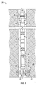
Figure 1 is a schematic illustration of an example of a well system utilizing a shock mitigation system, according to an embodiment of the disclosure; -
Figure 2 is a schematic illustration of an example of a shock mitigation system coupled with a communication system in a tool string, according to an embodiment of the disclosure; -
Figure 3 is a schematic illustration of a portion of the system illustrated inFigure 2 , according to an embodiment of the disclosure; -
Figure 4 is a side view of an example of a clutch which may be utilized in a shock mitigation system, according to an embodiment of the disclosure; -
Figure 5 is a side view of an example of a clutch similar to that ofFigure 4 but from an opposite side, according to an embodiment of the disclosure; -
Figure 6 is a cross-sectional view of an example of a clutch which may be utilized in a shock mitigation system, according to an embodiment of the disclosure; -
Figure 7 is a cross-sectional view of another example of a clutch which may be utilized in a shock mitigation system, according to an embodiment of the disclosure; -
Figure 8 is a cross-sectional view of another example of a clutch which may be utilized in a shock mitigation system, according to an embodiment of the disclosure; -
Figure 9 is a cross-sectional view of another example of a clutch which may be utilized in a shock mitigation system, according to an embodiment of the disclosure; -
Figure 10 is a cross-sectional view of another example of a clutch which may be utilized in a shock mitigation system, according to an embodiment of the disclosure; -
Figure 11 is a schematic illustration of an example of a shock mitigation component which may be utilized in a shock mitigation system, according to an embodiment of the disclosure; -
Figure 12 is a schematic illustration of another example of a shock mitigation component which may be utilized in a shock mitigation system, according to an embodiment of the disclosure; -
Figure 13 is a schematic illustration of another example of a shock mitigation component which may be utilized in a shock mitigation system, according to an embodiment of the disclosure; -
Figure 14 is a schematic illustration of another example of a shock mitigation component which may be utilized in a shock mitigation system, according to an embodiment of the disclosure; and -
Figure 15 is a schematic illustration of another example of a shock mitigation component which may be utilized in a shock mitigation system, according to an embodiment of the disclosure. - In the following description, numerous details are set forth to provide an understanding of some embodiments of the present disclosure. However, it will be understood by those of ordinary skill in the art that the system and/or methodology may be practiced without these details and that numerous variations or modifications from the described embodiments may be possible.
- The present disclosure generally relates to a methodology and system which facilitate mitigation of shock loads. According to an embodiment, a subterranean communication system, e.g. an acoustical telemetry system, may comprise components susceptible to shock loads. A shock mitigation system is physically coupled with the subterranean communication system to mitigate such shock loads. In various perforating operations, for example, large shock loads may be induced along a tool string upon firing of a perforating gun assembly. The shock mitigation system comprises components which reduce various effects of these shock loads so as to facilitate continued operation of the subterranean communication system.
- In various embodiments, acoustical telemetry systems are used to acoustically transmit signals along a tool string deployed in a wellbore. The acoustical telemetry system may be used to generate and/or receive signals in the form of acoustic waves which carry information uphole along the tool string or carry control signals downhole along the tool string. These types of acoustic and other communication systems are useful in subterranean Earth borehole type applications in various industries, such as the gas and oil industry.
- During development of gas and oil wells, a borehole is drilled and cased with steel tubing and cement/concrete. To enhance access to a pay zone of a surrounding formation, holes are created in the formation of interest by firing perforating gun assemblies. During detonation of shaped charges of the perforating gun assembly, pyrotechnic shock loads and hydrodynamic shock loads are generated. Acoustic modems/transducers and/or other components of the subterranean communication system can be damaged or rendered inoperable by such shock loads. Accordingly, the shock mitigation system is combined with the communication system, e.g. acoustical communication system, to protect components of the communication system from potentially detrimental shock loads.
- In applications utilizing an acoustical communication system, the shock mitigation system may be coupled with a movable acoustical member of the communication system in a manner which allows physical movement of the acoustical member while absorbing shock loads. In some acoustical communication systems, for example, acoustical signals are transmitted via an acoustical rod member and excess movement of the acoustical rod member can damage the communication system. However, the shock mitigation system may combine various shock mitigation components with the acoustical rod member (or other communication system member susceptible to shock load damage) to reduce the effects of shock loads.
- According to an embodiment, the shock mitigation system may be physically coupled to the acoustical rod member by, for example, a clutch. In some applications, the clutch effectively couples the acoustical rod member with a corresponding "modem" or other component for outputting or receiving transmitted acoustical signals. During sufficient shock loading, e.g. perforating shock loading, the rod member may slide inside the clutch at a predetermined rate. As the rod slides, an additional shock absorber/mitigator absorbs excess energy from the shock load, e.g. from the shock resulting from firing of the perforating gun assembly. The friction provided by the clutch also helps absorb shock energy.
- After the shock energy is absorbed, the rod member can move partially or fully back to its original position due to the biasing force applied via the shock absorber/mitigator components. However, the clutch still sufficiently clamps the acoustical rod member so the acoustical rod member remains acoustically coupled as desired within the acoustical communication system. For example, the acoustical rod member remains acoustically coupled with the "modem" or other acoustic transmission component. After the shock loading is absorbed and mitigated, the communication system thus recovers and is able to communicate acoustic signals while also being able to absorb subsequent shock loads.
- Referring generally to
Figure 1 , an embodiment of awell system 20 is illustrated as comprising a tool string 22 deployed downhole into awellbore 24 drilled into or through a formation 26. In this example, the tool string 22 comprises acommunication system 28, e.g. an acoustical communication system, coupled with ashock mitigation system 30. In applications utilizing acoustic communication, theacoustical communication system 28 may comprise a wireless telemetry system for outputting and/or receiving acoustic signals along the tool string 22 via anacoustical member 32. Theacoustical member 32 may be an acoustical rod member and is coupled with an appropriateacoustical device 33, e.g. a receiver or transceiver device which may be in the form of an acoustical signal transducer often referred to as a modem. - The
acoustical modem 33 is a device which converts computer-based telemetry signals into acoustic signals (or vice versa). Theacoustical modem 33 is coupled with acoustical member/rod 32 and acoustic signals flow through the acoustical member/rod 32.Acoustical member 32 also is connected to a bulkhead or other suitable structure via an acoustical clutch, embodiments of which are described in greater detail below. An example of an acoustical communication system is the MuZIC™ acoustical telemetry system available from Schlumberger Corporation although a variety ofother communication systems 28 may be used in many types of subterranean operations. - As further illustrated in
Figure 1 , theacoustic communication system 28 may be coupled with afiring device 34 which, in turn, is coupled with a perforatinggun assembly 36. In the example illustrated, the perforatinggun assembly 36 comprises asafety spacer 38 at its upper end. Additionally, the perforatinggun assembly 36 comprises a plurality of shapedcharges 40 which may be selectively detonated via firingdevice 34 in response to control signals relayed throughacoustical communication system 28. When the perforatinggun assembly 36 is fired, the shapedcharges 40 are detonated and createperforations 42 which extend outwardly into the surrounding formation 26. The force of the detonation sends shock loads along the tool string 22 which can potentially damage components ofcommunication system 28 without the shock absorption provided byshock mitigation system 30. - Depending on the specifics of a given application, the tool string 22 may comprise a variety of
other equipment 44, e.g. flow isolation valves, crossovers, pup joints, and/or other equipment. In some applications, the tool string 22 may comprisedrill pipe 46 and a packer orpackers 48 which may be used to selectively isolate portions of thewellbore 24. Various components and arrangements of components may be used along the tool string 22 in combination withcommunication system 28 andshock mitigation system 30. In some applications, the shock mitigation system 30 (or an additional shock mitigation system 30) may be used to mitigate shock loads with respect to other components along the tool string 22. - Referring generally to
Figure 2 , an embodiment ofshock mitigation system 30 combined with an embodiment ofacoustic communication system 28 is illustrated. In this example, theacoustic communication system 28 may comprise a variety of components includingfiring device 34 and associatedelectronics 50. Theacoustic communication system 28 may further comprise apressure housing 52 and aninternal battery 54 to provide electrical power for thecommunication system 28, including electrical power for thefiring device electronics 50. Additionally,communication system 28 comprisesacoustical member 32 engaged with corresponding acoustical modem 33 (or other suitable device). Theacoustical modem 33 may work in cooperation with apressure transducer 56. However, other and/or additional components may be incorporated into theacoustical communication system 28 according to the parameters of a given application. - Similarly, the
shock mitigation system 30 may comprise a variety of components. With additional reference toFigure 3 , an embodiment of theshock mitigation system 30 comprises an acoustical clutch 58 which effectively clamps againstacoustical member 32 so as to absorb shock loading by allowing controlled movement ofacoustical member 32. In some applications, themitigation system 30 may comprise additional shock mitigators, such as at least oneaxial shock mitigator 60 and at least one lateral, e.g. radial,shock mitigator 62. - The
acoustical clutch 58 serves as a clamping device which allows acoustical energy, during normal use, to be coupled between the acoustical member, e.g. rod, 32 and an associated bulkhead or other suitable structure, e.g. a bulkhead of themodem 33 as described below. During high shock loading, e.g. during detonation of perforatinggun assembly 36, the clamping force provided by acoustical clutch 58 againstrod 32 may be exceeded. This allows the acoustical rod 32 (and connected modem 33) to move in an axial direction but while limiting acceleration and dissipating energy via the resistance provided byclutch 58. For single uses, the acoustical clutch 58 may be a manually resettable clutch. For example, the clutch 58 may be constructed to absorb the full perforating shock energy and then manually reset when the tool is redressed. For multiple uses and auto resetting, e.g. automatic re-centering, of the clutch 58, a return spring mechanism may be employed to provide the automatic resetting. - In some embodiments, the acoustical clutch 58 works in cooperation with an
axial shock mitigator 60 which may be used to provide spring bias for the automatic resetting. According to an embodiment, theaxial shock mitigator 60 is a shock absorber constructed to absorb excess energy not absorbed byclutch 58. Depending on the construction of theaxial shock mitigator 60, the shock absorber may be used to return theacoustic modem 33 to a neutral position after the shock event, e.g. firing of perforatinggun assembly 36. Examples of shock absorbers used inaxial shock mitigator 60 include hydraulic shock absorbers, fiction springs, Belleville disc springs with dampers, rubber crush elements, or one time crush elements. Crush elements for one time use may be constructed from materials such as aluminum tubing, copper tubing, plastic tubing, and/or other suitable materials that can absorb excess energy. The crush elements also can be constructed in other forms and can be, for example, machined or molded. - Similarly, the acoustical clutch 58 may be used in cooperation with a
lateral shock mitigator 62. According to an embodiment, thelateral shock mitigator 62 may be a radially mounted elastic shock absorbing material positioned around theacoustical member 32 and/ormodem 33. By way of example, the elastic material may comprise a polymer and may include Teflon™, silicon rubber, Viton™ rubber, and/or other suitable materials. - Referring generally to
Figures 4-6 , an embodiment of acoustical clutch 58 is illustrated as clamped againstacoustical rod member 32. In this example, the acoustical clutch 58 also is coupled with abulkhead 64 ofmodem 33 to form a movable coupling betweenacoustical rod member 32 andbulkhead 64 ofmodem 33. By way of example, the acoustical clutch 58 may comprise cooperatingclutch components 66, as illustrated inFigures 4 and 5 . By way of example, the cooperatingclutch components 66 may comprise a machinedbulkhead portion 68 extending frombulkhead 64 and acover 70, as illustrated in the embodiment ofFigure 6 . Theclutch components 66 may be releasably coupled together by asuitable fastener 72, such as a plurality of clamping screws 74. - Additionally, a
saddle 76 or a plurality ofsaddles 76 may be clamped betweenclutch components 66 in a manner which forces the saddle(s) 76 against acoustical rod member 32 (seeFigure 6 ). In the example illustrated, each saddle 76 of acoustical clutch 58 comprises a profiledsection 78 having a profile selected for lateral engagement withacoustical rod member 32. The saddle(s) 76 may be biased againstacoustical rod member 32 via anappropriate biasing member 80, such as a spring member. In the example illustrated inFigure 6 , the biasingmember 80 comprises a plurality ofBelleville spring washers 82 arranged in stacks and held against the correspondingsaddle 76 bycover 70. The number and type ofBelleville spring washers 82 are selected to apply the desired amount of clamping force, e.g. friction, acting againstacoustical rod member 32. Thecover 70 may be secured against the correspondingclutch component 66, e.g. machinedbulkhead portion 68, via clamping screws 74. - It should be noted that various components, configurations of components, and/or materials may be used in the construction of acoustical clutch 58. For example, the
Belleville spring washers 82 provide a relatively high force in a small volume. However, biasingmember 80 also may be formed with other springs, e.g. coil springs or wave springs, which may be suitable in various applications. Additionally, the biasingmember 80 may be formed from a variety of suitable spring materials, such as steel, stainless steel, beryllium copper, beryllium nickel, or other suitable materials or combinations of materials. As illustrated inFigure 5 , the biasingmember 80 may be arranged in three spring sets but other numbers of spring sets also may be used according to the parameters of a given application. - Similarly, the
saddle 76 may be constructed from a variety of materials and in a variety of configurations. Generally, the material is selected to allow motion of theacoustical rod member 32 relative to saddle 76 while still being able to support the forces generated by biasingmember 80. In some applications, saddle 76 may be constructed from the same type of material used to construct machinedbulkhead portion 68. Thecover 70 also may be constructed from a variety of suitable materials, including the same type of material used to form the machinedbulkhead portion 68. - In the example illustrated, the machined
bulkhead portion 68 extends frombulkhead 64 andbulkhead 64 serves as a pressure bulkhead into which theacoustical clutch 58 is integrated. The material ofbulkhead 64 is selected according to the pressures, temperatures, fluids, and/or other environmental factors associated with a given application. The material and structure of theacoustical rod 32 is selected so as to support the mass ofmodem 33 while also being able to transfer acoustical energy into thebulkhead 64 through theacoustical clutch 58. In many applications, theacoustical rod member 32 may be formed from aluminum bronze but other materials, e.g. steels, stainless steels, brasses, also may be used in a variety of applications. - Referring generally to
Figures 7-10 , other embodiments of acoustical clutch 58 are illustrated. In the embodiment ofFigure 7 , for example, the biasingmember 80 is formed with a singleBelleville spring washer 82 instead of a stack of thewashers 82 as in the previous embodiment. In some applications, the biasingmember 80 may be in the form of a stampedsheet metal clamp 84, as illustrated inFigure 8 . Thesheet metal clamp 84 is constructed to apply sufficient lateral force to theacoustical rod 32 so as to create the desired friction. In some applications, thesheet metal clamp 84 may include compliance bends 86 which allow for temperature compensation and machining tolerance stack-up considerations. - The biasing
member 80 also may comprise a machinedclamp 88, as illustrated inFigure 9 . The machinedclamp 88 may comprise compliancestress relief cuts 90 which also are constructed for temperature compensation and machining tolerance stack-up considerations. In some applications, however, the biasingmember 80 may effectively comprise the clamping screws 74 as illustrated inFigure 10 . In this type of arrangement, the cooperating clutch components 66 (or a separate inserted component) simply act against theacoustical rod 32 upon tightening of the clamping screws 74. The torque applied to the clamping screws 74 controls the clamping force applied to theacoustical rod 32. - Referring generally to
Figures 11-15 , various embodiments of the shock mitigators, e.g.axial shock mitigator 60, are illustrated. In the embodiment illustrated inFigure 11 , for example,axial shock mitigator 60 is constructed with elastomericshock absorbing element 92, e.g. twoshock absorbing elements 92, coupled toacoustical rod member 32 by acoupling bushing 93, e.g. twocoupling bushings 93, within a shockmitigation system housing 94. The elastomericshock absorbing elements 92 may be constructed from rubber or from another suitable shock absorbing material. Additionally, the elastomericshock absorbing elements 92 may be coupled betweenacoustical rod 32 and surroundingfriction spring elements 96 by apiston cup 97, e.g. twopiston cups 97. The surroundingfriction spring elements 96 may be disposed along the interior ofhousing 94. By way of example, thefriction spring elements 96 may comprise elastic elements such as spring steel, but they also may comprise a variety of other materials. - The
friction spring elements 96 work in cooperation withshock absorbing elements 92 to provide a desired resistance to motion ofrod 32. Effectively, the shock load absorbing characteristics ofshock absorbing elements 92 andfriction spring elements 96 cooperate to dissipate axial shock loads acting throughrod 32 while still maintaining an acoustical connection betweenacoustical rod 32, acoustical clutch 58, andbulkhead 64/modem 33 to enable transmission of acoustic signals. To at least some extent, thefriction spring elements 96 also may dissipate lateral, e.g. radial, shock loads. In some embodiments, thefriction spring elements 96 may be used as the primary shock absorbing elements while theshock absorbing elements 92 effectively provide bumpers which serve as secondary shock absorbing elements to dampen high frequency vibration. - Another embodiment of
axial shock mitigator 60 is illustrated inFigure 12 . In this embodiment, theaxial shock mitigator 60 comprises ahydraulic shock absorber 98 which may include ahydraulic fluid 100. Apiston 102 is coupled withacoustical rod 32 and moves throughhydraulic fluid 100 whenacoustical rod 32 is shifted by, for example, shock loads resulting from firing of perforatinggun assembly 36. Thepiston 102 comprisesflow passages 104 which enable a limited amount of thehydraulic fluid 100 to pass along theflow passages 104 whenpiston 102 is moved along the surroundingsystem housing 94, thus absorbing and mitigating shock loads. Thepiston 102 also may be frictionally engaged with the surrounding cylinder wall ofhousing 94 so as to retain an acoustical coupling. - Similar resistance to movement of
acoustical rod 32 and corresponding mitigation of shock loads may be achieved by frictionally engaging theacoustical rod 32 with arubber shock absorber 106, as illustrated inFigure 13 . In this embodiment, shock loading is absorbed and mitigated by a plurality ofrubber components 108 disposed betweenacoustical rod 32 and the surroundingsystem housing 94 so as to provide frictional resistance to movement ofacoustical rod 32 while still maintaining the acoustical coupling. - Referring generally to
Figures 14 and 15 , additional embodiments of theshock mitigation system 30 are illustrated. In the embodiment illustrated inFigure 14 , theaxial shock mitigator 60 may comprise a stack of Belleville disc springs 110 which absorb shock loads while compressing sufficiently to allow sufficient linear movement ofacoustical rod member 32 for transfer of acoustical signals. By way of example, therod 32 may be coupled with aload transfer member 112 which acts against the stack of Belleville disc brings 110 to absorb shock loads while still allowing acoustical movement of therod 32. It should be noted that acoustical clutch 58 also may have a variety of configurations, including a plurality of spring-loadedball rollers 114 positioned to act laterally against theacoustical rod 32, as illustrated inFigure 14 . - In the embodiment illustrated in
Figure 15 , a plurality of theaxial shock mitigators 60 is employed. Depending on the application, various types of theaxial shock mitigators 60 may be used at various positions alongacoustical rod 32 and/oracoustical modem 33. In the example illustrated, anaxial shock mitigator 60 is positioned at each end of theacoustical modem 33 to absorb shock loading experienced bymodem 33 while also allowing theacoustical modem 33 to return to a neutral position for subsequent use in transmitting acoustic signals. - The acoustical clutch 58, axial shock mitigator(s) 60, and lateral shock mitigator(s) 62 may be used individually or in various combinations and configurations to establish the desired
shock mitigation system 30. A specific configuration may be selected according to the parameters of a given application. Theshock mitigation system 30 is constructed to protect theacoustical modem 33 and/or other communication system components during substantial shock loading, such as that experienced during firing of the perforatinggun assembly 36. Inembodiments utilizing modem 33, theshock mitigation system 30 isolates theacoustical modem 33 during, for example, perforation procedures while enabling retention of an operable acoustical coupling following the perforating procedure. - In various embodiments described above, the
acoustical clamp 58 allows acoustical energy to be transmitted and received to and from themodem 33 through thebulkhead 64 andacoustical rod 32. However theacoustical clamp 58 is readily used in cooperation withshock mitigator 60 and/orshock mitigator 62 to absorb detrimental shock loads so as to enable continued transfer of acoustical energy after thecommunication system 28 experiences a high shock environment. - The modem 33 (and/or other communication system components) may thus be exposed to the acceleration resulting from shock loading, but the shock absorbing capability of the clutch 58 with
corresponding shock mitigators 60/62 moderates the shock experienced by themodem 33 and/or other protected components. Examples of other components that may be protected byshock mitigation system 30 include repeaters located belowpacker 48. In perforating applications, themodem 33 or other susceptible components are isolated from the shocks that result from firing of the perforatinggun assembly 36 while effectively enabling mechanical reconnection of the acoustical communication system components after perforation so that acoustical communications can continue. - Depending on the application, the
shock mitigation system 30 may be used with several types of well equipment or non-well related equipment for isolating components from excessive shock loading while enabling retention of a mechanical linkage between components. However, features of theshock mitigation system 30 also may be used to protect a variety of standalone components or linked components in communication systems and other susceptible systems. In well applications, the shock mitigation system may be used to protect not simply acoustical modems but also a variety of other telemetry system components. Various configurations and arrangements of thecomponents shock mitigation system 30 can be assembled to protect many types of sensitive components that may be subjected to short-term but high shock loading environments. - Although a few embodiments of the disclosure have been described in detail above, those of ordinary skill in the art will readily appreciate that many modifications are possible without materially departing from the teachings of this disclosure. Accordingly, such modifications are intended to be included within the scope of this disclosure as defined in the claims.
Claims (20)
- A system for use a well, comprising:a tool string deployed in a wellbore, the tool string having:a perforating gun assembly;an acoustical communication system; anda shock mitigation system mounted along the tool string to mitigate shocks to the acoustical communication system resulting from firing of the perforating gun assembly.
- The system as recited in claim 1, wherein the shock mitigation system comprises an acoustical clutch.
- The system as recited in claim 2, wherein the shock mitigation system comprises an axial shock mitigator.
- The system as recited in claim 3, wherein the shock mitigation system comprises a radial shock mitigator.
- The system as recited in claim 4, wherein the acoustical communication system comprises an acoustical rod member and the acoustical clutch comprises a saddle which is spring biased against the acoustical rod member.
- The system as recited in claim 5, wherein the saddle is spring biased via a Belleville washer.
- The system as recited in claim 5, wherein the saddle is spring biased via a plurality of Belleville washers.
- The system as recited in claim 5, wherein the saddle is spring biased via a clamp.
- The system as recited in claim 5, wherein at least one of the axial shock mitigator or radial shock mitigator comprises an elastomeric shock absorber.
- The system as recited in claim 5, wherein at least one of the axial shock mitigator or radial shock mitigator comprises a hydraulic shock absorber.
- A method, comprising:coupling a perforating gun assembly into a tool string;providing the tool string with a communication system for transmitting telemetry signals along the tool string; andprotecting the communication system against shock loads via a shock mitigation system operatively coupled with the communication system.
- The method as recited in claim 11, wherein providing comprises providing the tool string with the communication system in the form of an acoustical communication system having an acoustical rod member used to carry acoustic signals.
- The method as recited in claim 12, wherein protecting comprises biasing an acoustical clutch, of the shock mitigation system, against the acoustical rod member.
- The method as recited in claim 13, wherein protecting comprises employing an axial shock mitigator, of the shock mitigation system, against the acoustical rod member.
- The method as recited in claim 13, wherein protecting comprises employing a radial shock mitigator, of the shock mitigation system, against the acoustical rod member
- The method as recited in claim 13, wherein employing the acoustical clutch comprises spring biasing a saddle against acoustical rod member.
- A system, comprising:a subterranean communication system susceptible to shock loads; anda shock mitigation system physically coupled to the subterranean communication system, the shock mitigation system comprising a clutch which enables movement of at least a component of the subterranean communication system when subjected to a sufficient shock load, the shock mitigation system further comprising an axial shock mitigator and a lateral shock mitigator.
- The system as recited in claim 17, wherein the subterranean communication system and the shock mitigation system are coupled into a tool string located in a wellbore.
- The system as recited in claim 18, further comprising a perforating gun assembly coupled into the tool string.
- The system as recited in claim 19, wherein the subterranean communication system comprises an acoustical communication system.
Applications Claiming Priority (2)
| Application Number | Priority Date | Filing Date | Title |
|---|---|---|---|
| US201562187013P | 2015-06-30 | 2015-06-30 | |
| US15/188,644 US10246975B2 (en) | 2015-06-30 | 2016-06-21 | System and method for shock mitigation |
Publications (2)
| Publication Number | Publication Date |
|---|---|
| EP3112584A1 true EP3112584A1 (en) | 2017-01-04 |
| EP3112584B1 EP3112584B1 (en) | 2018-12-26 |
Family
ID=56296682
Family Applications (1)
| Application Number | Title | Priority Date | Filing Date |
|---|---|---|---|
| EP16177218.1A Active EP3112584B1 (en) | 2015-06-30 | 2016-06-30 | System and method for shock mitigation |
Country Status (2)
| Country | Link |
|---|---|
| US (2) | US10246975B2 (en) |
| EP (1) | EP3112584B1 (en) |
Cited By (1)
| Publication number | Priority date | Publication date | Assignee | Title |
|---|---|---|---|---|
| US20170226845A1 (en) * | 2016-02-07 | 2017-08-10 | Schlumberger Technology Corporation | Shock and vibration damper system and methodology |
Families Citing this family (3)
| Publication number | Priority date | Publication date | Assignee | Title |
|---|---|---|---|---|
| US10295500B2 (en) * | 2014-03-27 | 2019-05-21 | Ultrapower Inc. | Electro-acoustic sensors for remote monitoring |
| US10246975B2 (en) * | 2015-06-30 | 2019-04-02 | Schlumberger Technology Corporation | System and method for shock mitigation |
| USD979611S1 (en) | 2020-08-03 | 2023-02-28 | XConnect, LLC | Bridged mini-bulkheads |
Citations (4)
| Publication number | Priority date | Publication date | Assignee | Title |
|---|---|---|---|---|
| US4693317A (en) * | 1985-06-03 | 1987-09-15 | Halliburton Company | Method and apparatus for absorbing shock |
| US20120152614A1 (en) * | 2010-12-17 | 2012-06-21 | Halliburton Energy Services, Inc. | Coupler compliance tuning for mitigating shock produced by well perforating |
| EP2597250A1 (en) * | 2011-11-24 | 2013-05-29 | Services Pétroliers Schlumberger | Longitudinal absorber for downhole tool chassis |
| US20150090452A1 (en) * | 2013-09-27 | 2015-04-02 | Schlumberger Technology Corporation | Shock mitigator |
Family Cites Families (11)
| Publication number | Priority date | Publication date | Assignee | Title |
|---|---|---|---|---|
| US4817710A (en) * | 1985-06-03 | 1989-04-04 | Halliburton Company | Apparatus for absorbing shock |
| US6378607B1 (en) * | 1999-06-09 | 2002-04-30 | Schlumberger Technology Corporation | Method and system for oriented perforating in a well with permanent sensors |
| GB2374887B (en) * | 2001-04-27 | 2003-12-17 | Schlumberger Holdings | Method and apparatus for orienting perforating devices |
| US20090151589A1 (en) * | 2007-12-17 | 2009-06-18 | Schlumberger Technology Corporation | Explosive shock dissipater |
| US8276656B2 (en) | 2007-12-21 | 2012-10-02 | Schlumberger Technology Corporation | System and method for mitigating shock effects during perforating |
| US8136608B2 (en) | 2008-12-16 | 2012-03-20 | Schlumberger Technology Corporation | Mitigating perforating gun shock |
| WO2011137059A2 (en) * | 2010-04-30 | 2011-11-03 | Applied Materials, Inc. | Amorphous carbon deposition method for improved stack defectivity |
| US20120155219A1 (en) * | 2010-12-10 | 2012-06-21 | Laurent Alteirac | System and Method for Acoustic Recording in Well Bottomhole Assembly while Firing A Perforating Gun |
| US9091152B2 (en) * | 2011-08-31 | 2015-07-28 | Halliburton Energy Services, Inc. | Perforating gun with internal shock mitigation |
| CA2941520A1 (en) * | 2014-03-06 | 2015-09-11 | Shell Internationale Research Maatschappij B.V. | Method and apparatus for reservoir testing and monitoring |
| US10246975B2 (en) * | 2015-06-30 | 2019-04-02 | Schlumberger Technology Corporation | System and method for shock mitigation |
-
2016
- 2016-06-21 US US15/188,644 patent/US10246975B2/en active Active
- 2016-06-30 EP EP16177218.1A patent/EP3112584B1/en active Active
-
2019
- 2019-04-01 US US16/372,034 patent/US10975672B2/en active Active
Patent Citations (4)
| Publication number | Priority date | Publication date | Assignee | Title |
|---|---|---|---|---|
| US4693317A (en) * | 1985-06-03 | 1987-09-15 | Halliburton Company | Method and apparatus for absorbing shock |
| US20120152614A1 (en) * | 2010-12-17 | 2012-06-21 | Halliburton Energy Services, Inc. | Coupler compliance tuning for mitigating shock produced by well perforating |
| EP2597250A1 (en) * | 2011-11-24 | 2013-05-29 | Services Pétroliers Schlumberger | Longitudinal absorber for downhole tool chassis |
| US20150090452A1 (en) * | 2013-09-27 | 2015-04-02 | Schlumberger Technology Corporation | Shock mitigator |
Cited By (2)
| Publication number | Priority date | Publication date | Assignee | Title |
|---|---|---|---|---|
| US20170226845A1 (en) * | 2016-02-07 | 2017-08-10 | Schlumberger Technology Corporation | Shock and vibration damper system and methodology |
| US10458226B2 (en) * | 2016-02-07 | 2019-10-29 | Schlumberger Technology Corporation | Shock and vibration damper system and methodology |
Also Published As
| Publication number | Publication date |
|---|---|
| US20170002633A1 (en) | 2017-01-05 |
| US10975672B2 (en) | 2021-04-13 |
| EP3112584B1 (en) | 2018-12-26 |
| US10246975B2 (en) | 2019-04-02 |
| US20190226305A1 (en) | 2019-07-25 |
Similar Documents
| Publication | Publication Date | Title |
|---|---|---|
| US10975672B2 (en) | System and method for shock mitigation | |
| CA2314192C (en) | Downhole shock absorber | |
| EP0489527B1 (en) | Downhole hydraulic shock absorber | |
| AU592370B2 (en) | Method and apparatus for absorbing shock | |
| US4817710A (en) | Apparatus for absorbing shock | |
| US8397800B2 (en) | Perforating string with longitudinal shock de-coupler | |
| RU2625682C1 (en) | Reduction method of the torsional vibration in the borehole and corresponding device | |
| US9328567B2 (en) | Double-acting shock damper for a downhole assembly | |
| AU2011341709B2 (en) | Perforating string with longitudinal shock de-coupler | |
| GB2375125A (en) | Shock absorber apparatus | |
| US20160290066A1 (en) | Shock absorbing ubho/pulser sub assembly with optional mud filter | |
| US20150159719A1 (en) | Isolator | |
| EP3097264B1 (en) | Isolating mule shoe | |
| WO2020205138A1 (en) | Lateral isolator | |
| EP3137718B1 (en) | Snubber for downhole tool | |
| WO2022026742A1 (en) | Shock isolator device and related methods | |
| WO2022015921A1 (en) | Adjustable strength shock absorber system for downhole ballistics | |
| US11215017B2 (en) | Perforating shock protection for sensors | |
| CN115698466A (en) | Hydrostatically actuatable systems and related methods |
Legal Events
| Date | Code | Title | Description |
|---|---|---|---|
| PUAI | Public reference made under article 153(3) epc to a published international application that has entered the european phase |
Free format text: ORIGINAL CODE: 0009012 |
|
| STAA | Information on the status of an ep patent application or granted ep patent |
Free format text: STATUS: THE APPLICATION HAS BEEN PUBLISHED |
|
| AK | Designated contracting states |
Kind code of ref document: A1 Designated state(s): AL AT BE BG CH CY CZ DE DK EE ES FI FR GB GR HR HU IE IS IT LI LT LU LV MC MK MT NL NO PL PT RO RS SE SI SK SM TR |
|
| AX | Request for extension of the european patent |
Extension state: BA ME |
|
| STAA | Information on the status of an ep patent application or granted ep patent |
Free format text: STATUS: REQUEST FOR EXAMINATION WAS MADE |
|
| 17P | Request for examination filed |
Effective date: 20171012 |
|
| RBV | Designated contracting states (corrected) |
Designated state(s): AL AT BE BG CH CY CZ DE DK EE ES FI FR GB GR HR HU IE IS IT LI LT LU LV MC MK MT NL NO PL PT RO RS SE SI SK SM TR |
|
| STAA | Information on the status of an ep patent application or granted ep patent |
Free format text: STATUS: EXAMINATION IS IN PROGRESS |
|
| 17Q | First examination report despatched |
Effective date: 20180227 |
|
| GRAP | Despatch of communication of intention to grant a patent |
Free format text: ORIGINAL CODE: EPIDOSNIGR1 |
|
| STAA | Information on the status of an ep patent application or granted ep patent |
Free format text: STATUS: GRANT OF PATENT IS INTENDED |
|
| INTG | Intention to grant announced |
Effective date: 20180719 |
|
| GRAS | Grant fee paid |
Free format text: ORIGINAL CODE: EPIDOSNIGR3 |
|
| GRAA | (expected) grant |
Free format text: ORIGINAL CODE: 0009210 |
|
| STAA | Information on the status of an ep patent application or granted ep patent |
Free format text: STATUS: THE PATENT HAS BEEN GRANTED |
|
| AK | Designated contracting states |
Kind code of ref document: B1 Designated state(s): AL AT BE BG CH CY CZ DE DK EE ES FI FR GB GR HR HU IE IS IT LI LT LU LV MC MK MT NL NO PL PT RO RS SE SI SK SM TR |
|
| REG | Reference to a national code |
Ref country code: GB Ref legal event code: FG4D |
|
| REG | Reference to a national code |
Ref country code: CH Ref legal event code: EP |
|
| REG | Reference to a national code |
Ref country code: AT Ref legal event code: REF Ref document number: 1081690 Country of ref document: AT Kind code of ref document: T Effective date: 20190115 |
|
| REG | Reference to a national code |
Ref country code: DE Ref legal event code: R096 Ref document number: 602016008605 Country of ref document: DE |
|
| REG | Reference to a national code |
Ref country code: IE Ref legal event code: FG4D |
|
| PG25 | Lapsed in a contracting state [announced via postgrant information from national office to epo] |
Ref country code: FI Free format text: LAPSE BECAUSE OF FAILURE TO SUBMIT A TRANSLATION OF THE DESCRIPTION OR TO PAY THE FEE WITHIN THE PRESCRIBED TIME-LIMIT Effective date: 20181226 Ref country code: LV Free format text: LAPSE BECAUSE OF FAILURE TO SUBMIT A TRANSLATION OF THE DESCRIPTION OR TO PAY THE FEE WITHIN THE PRESCRIBED TIME-LIMIT Effective date: 20181226 Ref country code: LT Free format text: LAPSE BECAUSE OF FAILURE TO SUBMIT A TRANSLATION OF THE DESCRIPTION OR TO PAY THE FEE WITHIN THE PRESCRIBED TIME-LIMIT Effective date: 20181226 Ref country code: HR Free format text: LAPSE BECAUSE OF FAILURE TO SUBMIT A TRANSLATION OF THE DESCRIPTION OR TO PAY THE FEE WITHIN THE PRESCRIBED TIME-LIMIT Effective date: 20181226 Ref country code: BG Free format text: LAPSE BECAUSE OF FAILURE TO SUBMIT A TRANSLATION OF THE DESCRIPTION OR TO PAY THE FEE WITHIN THE PRESCRIBED TIME-LIMIT Effective date: 20190326 |
|
| REG | Reference to a national code |
Ref country code: NL Ref legal event code: MP Effective date: 20181226 |
|
| REG | Reference to a national code |
Ref country code: LT Ref legal event code: MG4D |
|
| PG25 | Lapsed in a contracting state [announced via postgrant information from national office to epo] |
Ref country code: RS Free format text: LAPSE BECAUSE OF FAILURE TO SUBMIT A TRANSLATION OF THE DESCRIPTION OR TO PAY THE FEE WITHIN THE PRESCRIBED TIME-LIMIT Effective date: 20181226 Ref country code: GR Free format text: LAPSE BECAUSE OF FAILURE TO SUBMIT A TRANSLATION OF THE DESCRIPTION OR TO PAY THE FEE WITHIN THE PRESCRIBED TIME-LIMIT Effective date: 20190327 Ref country code: AL Free format text: LAPSE BECAUSE OF FAILURE TO SUBMIT A TRANSLATION OF THE DESCRIPTION OR TO PAY THE FEE WITHIN THE PRESCRIBED TIME-LIMIT Effective date: 20181226 Ref country code: SE Free format text: LAPSE BECAUSE OF FAILURE TO SUBMIT A TRANSLATION OF THE DESCRIPTION OR TO PAY THE FEE WITHIN THE PRESCRIBED TIME-LIMIT Effective date: 20181226 |
|
| REG | Reference to a national code |
Ref country code: AT Ref legal event code: MK05 Ref document number: 1081690 Country of ref document: AT Kind code of ref document: T Effective date: 20181226 |
|
| REG | Reference to a national code |
Ref country code: NO Ref legal event code: T2 Effective date: 20181226 |
|
| PG25 | Lapsed in a contracting state [announced via postgrant information from national office to epo] |
Ref country code: NL Free format text: LAPSE BECAUSE OF FAILURE TO SUBMIT A TRANSLATION OF THE DESCRIPTION OR TO PAY THE FEE WITHIN THE PRESCRIBED TIME-LIMIT Effective date: 20181226 |
|
| PG25 | Lapsed in a contracting state [announced via postgrant information from national office to epo] |
Ref country code: ES Free format text: LAPSE BECAUSE OF FAILURE TO SUBMIT A TRANSLATION OF THE DESCRIPTION OR TO PAY THE FEE WITHIN THE PRESCRIBED TIME-LIMIT Effective date: 20181226 Ref country code: IT Free format text: LAPSE BECAUSE OF FAILURE TO SUBMIT A TRANSLATION OF THE DESCRIPTION OR TO PAY THE FEE WITHIN THE PRESCRIBED TIME-LIMIT Effective date: 20181226 Ref country code: CZ Free format text: LAPSE BECAUSE OF FAILURE TO SUBMIT A TRANSLATION OF THE DESCRIPTION OR TO PAY THE FEE WITHIN THE PRESCRIBED TIME-LIMIT Effective date: 20181226 Ref country code: PT Free format text: LAPSE BECAUSE OF FAILURE TO SUBMIT A TRANSLATION OF THE DESCRIPTION OR TO PAY THE FEE WITHIN THE PRESCRIBED TIME-LIMIT Effective date: 20190426 Ref country code: PL Free format text: LAPSE BECAUSE OF FAILURE TO SUBMIT A TRANSLATION OF THE DESCRIPTION OR TO PAY THE FEE WITHIN THE PRESCRIBED TIME-LIMIT Effective date: 20181226 |
|
| PG25 | Lapsed in a contracting state [announced via postgrant information from national office to epo] |
Ref country code: EE Free format text: LAPSE BECAUSE OF FAILURE TO SUBMIT A TRANSLATION OF THE DESCRIPTION OR TO PAY THE FEE WITHIN THE PRESCRIBED TIME-LIMIT Effective date: 20181226 Ref country code: SM Free format text: LAPSE BECAUSE OF FAILURE TO SUBMIT A TRANSLATION OF THE DESCRIPTION OR TO PAY THE FEE WITHIN THE PRESCRIBED TIME-LIMIT Effective date: 20181226 Ref country code: SK Free format text: LAPSE BECAUSE OF FAILURE TO SUBMIT A TRANSLATION OF THE DESCRIPTION OR TO PAY THE FEE WITHIN THE PRESCRIBED TIME-LIMIT Effective date: 20181226 Ref country code: RO Free format text: LAPSE BECAUSE OF FAILURE TO SUBMIT A TRANSLATION OF THE DESCRIPTION OR TO PAY THE FEE WITHIN THE PRESCRIBED TIME-LIMIT Effective date: 20181226 Ref country code: IS Free format text: LAPSE BECAUSE OF FAILURE TO SUBMIT A TRANSLATION OF THE DESCRIPTION OR TO PAY THE FEE WITHIN THE PRESCRIBED TIME-LIMIT Effective date: 20190426 |
|
| REG | Reference to a national code |
Ref country code: DE Ref legal event code: R097 Ref document number: 602016008605 Country of ref document: DE |
|
| PG25 | Lapsed in a contracting state [announced via postgrant information from national office to epo] |
Ref country code: AT Free format text: LAPSE BECAUSE OF FAILURE TO SUBMIT A TRANSLATION OF THE DESCRIPTION OR TO PAY THE FEE WITHIN THE PRESCRIBED TIME-LIMIT Effective date: 20181226 Ref country code: DK Free format text: LAPSE BECAUSE OF FAILURE TO SUBMIT A TRANSLATION OF THE DESCRIPTION OR TO PAY THE FEE WITHIN THE PRESCRIBED TIME-LIMIT Effective date: 20181226 |
|
| PLBE | No opposition filed within time limit |
Free format text: ORIGINAL CODE: 0009261 |
|
| STAA | Information on the status of an ep patent application or granted ep patent |
Free format text: STATUS: NO OPPOSITION FILED WITHIN TIME LIMIT |
|
| 26N | No opposition filed |
Effective date: 20190927 |
|
| REG | Reference to a national code |
Ref country code: DE Ref legal event code: R119 Ref document number: 602016008605 Country of ref document: DE |
|
| PG25 | Lapsed in a contracting state [announced via postgrant information from national office to epo] |
Ref country code: MC Free format text: LAPSE BECAUSE OF FAILURE TO SUBMIT A TRANSLATION OF THE DESCRIPTION OR TO PAY THE FEE WITHIN THE PRESCRIBED TIME-LIMIT Effective date: 20181226 |
|
| REG | Reference to a national code |
Ref country code: CH Ref legal event code: PL |
|
| PG25 | Lapsed in a contracting state [announced via postgrant information from national office to epo] |
Ref country code: SI Free format text: LAPSE BECAUSE OF FAILURE TO SUBMIT A TRANSLATION OF THE DESCRIPTION OR TO PAY THE FEE WITHIN THE PRESCRIBED TIME-LIMIT Effective date: 20181226 |
|
| REG | Reference to a national code |
Ref country code: BE Ref legal event code: MM Effective date: 20190630 |
|
| PG25 | Lapsed in a contracting state [announced via postgrant information from national office to epo] |
Ref country code: TR Free format text: LAPSE BECAUSE OF FAILURE TO SUBMIT A TRANSLATION OF THE DESCRIPTION OR TO PAY THE FEE WITHIN THE PRESCRIBED TIME-LIMIT Effective date: 20181226 |
|
| PG25 | Lapsed in a contracting state [announced via postgrant information from national office to epo] |
Ref country code: IE Free format text: LAPSE BECAUSE OF NON-PAYMENT OF DUE FEES Effective date: 20190630 Ref country code: DE Free format text: LAPSE BECAUSE OF NON-PAYMENT OF DUE FEES Effective date: 20200101 |
|
| PG25 | Lapsed in a contracting state [announced via postgrant information from national office to epo] |
Ref country code: CH Free format text: LAPSE BECAUSE OF NON-PAYMENT OF DUE FEES Effective date: 20190630 Ref country code: LI Free format text: LAPSE BECAUSE OF NON-PAYMENT OF DUE FEES Effective date: 20190630 Ref country code: LU Free format text: LAPSE BECAUSE OF NON-PAYMENT OF DUE FEES Effective date: 20190630 Ref country code: BE Free format text: LAPSE BECAUSE OF NON-PAYMENT OF DUE FEES Effective date: 20190630 |
|
| PG25 | Lapsed in a contracting state [announced via postgrant information from national office to epo] |
Ref country code: FR Free format text: LAPSE BECAUSE OF NON-PAYMENT OF DUE FEES Effective date: 20190630 |
|
| PG25 | Lapsed in a contracting state [announced via postgrant information from national office to epo] |
Ref country code: CY Free format text: LAPSE BECAUSE OF FAILURE TO SUBMIT A TRANSLATION OF THE DESCRIPTION OR TO PAY THE FEE WITHIN THE PRESCRIBED TIME-LIMIT Effective date: 20181226 |
|
| PG25 | Lapsed in a contracting state [announced via postgrant information from national office to epo] |
Ref country code: HU Free format text: LAPSE BECAUSE OF FAILURE TO SUBMIT A TRANSLATION OF THE DESCRIPTION OR TO PAY THE FEE WITHIN THE PRESCRIBED TIME-LIMIT; INVALID AB INITIO Effective date: 20160630 Ref country code: MT Free format text: LAPSE BECAUSE OF FAILURE TO SUBMIT A TRANSLATION OF THE DESCRIPTION OR TO PAY THE FEE WITHIN THE PRESCRIBED TIME-LIMIT Effective date: 20181226 |
|
| PG25 | Lapsed in a contracting state [announced via postgrant information from national office to epo] |
Ref country code: MK Free format text: LAPSE BECAUSE OF FAILURE TO SUBMIT A TRANSLATION OF THE DESCRIPTION OR TO PAY THE FEE WITHIN THE PRESCRIBED TIME-LIMIT Effective date: 20181226 |
|
| PGFP | Annual fee paid to national office [announced via postgrant information from national office to epo] |
Ref country code: NO Payment date: 20230608 Year of fee payment: 8 |
|
| PGFP | Annual fee paid to national office [announced via postgrant information from national office to epo] |
Ref country code: GB Payment date: 20230511 Year of fee payment: 8 |
|
| P01 | Opt-out of the competence of the unified patent court (upc) registered |
Effective date: 20231208 |