EP3112494A1 - Method for forming thermally sprayed coating - Google Patents
Method for forming thermally sprayed coating Download PDFInfo
- Publication number
- EP3112494A1 EP3112494A1 EP15754635.9A EP15754635A EP3112494A1 EP 3112494 A1 EP3112494 A1 EP 3112494A1 EP 15754635 A EP15754635 A EP 15754635A EP 3112494 A1 EP3112494 A1 EP 3112494A1
- Authority
- EP
- European Patent Office
- Prior art keywords
- cylinder
- cylinder bore
- sprayed
- bore
- sprayed coating
- Prior art date
- Legal status (The legal status is an assumption and is not a legal conclusion. Google has not performed a legal analysis and makes no representation as to the accuracy of the status listed.)
- Withdrawn
Links
Images


Classifications
-
- C—CHEMISTRY; METALLURGY
- C23—COATING METALLIC MATERIAL; COATING MATERIAL WITH METALLIC MATERIAL; CHEMICAL SURFACE TREATMENT; DIFFUSION TREATMENT OF METALLIC MATERIAL; COATING BY VACUUM EVAPORATION, BY SPUTTERING, BY ION IMPLANTATION OR BY CHEMICAL VAPOUR DEPOSITION, IN GENERAL; INHIBITING CORROSION OF METALLIC MATERIAL OR INCRUSTATION IN GENERAL
- C23C—COATING METALLIC MATERIAL; COATING MATERIAL WITH METALLIC MATERIAL; SURFACE TREATMENT OF METALLIC MATERIAL BY DIFFUSION INTO THE SURFACE, BY CHEMICAL CONVERSION OR SUBSTITUTION; COATING BY VACUUM EVAPORATION, BY SPUTTERING, BY ION IMPLANTATION OR BY CHEMICAL VAPOUR DEPOSITION, IN GENERAL
- C23C4/00—Coating by spraying the coating material in the molten state, e.g. by flame, plasma or electric discharge
- C23C4/12—Coating by spraying the coating material in the molten state, e.g. by flame, plasma or electric discharge characterised by the method of spraying
-
- F—MECHANICAL ENGINEERING; LIGHTING; HEATING; WEAPONS; BLASTING
- F02—COMBUSTION ENGINES; HOT-GAS OR COMBUSTION-PRODUCT ENGINE PLANTS
- F02F—CYLINDERS, PISTONS OR CASINGS, FOR COMBUSTION ENGINES; ARRANGEMENTS OF SEALINGS IN COMBUSTION ENGINES
- F02F1/00—Cylinders; Cylinder heads
-
- F—MECHANICAL ENGINEERING; LIGHTING; HEATING; WEAPONS; BLASTING
- F02—COMBUSTION ENGINES; HOT-GAS OR COMBUSTION-PRODUCT ENGINE PLANTS
- F02F—CYLINDERS, PISTONS OR CASINGS, FOR COMBUSTION ENGINES; ARRANGEMENTS OF SEALINGS IN COMBUSTION ENGINES
- F02F1/00—Cylinders; Cylinder heads
- F02F1/004—Cylinder liners
-
- F—MECHANICAL ENGINEERING; LIGHTING; HEATING; WEAPONS; BLASTING
- F02—COMBUSTION ENGINES; HOT-GAS OR COMBUSTION-PRODUCT ENGINE PLANTS
- F02F—CYLINDERS, PISTONS OR CASINGS, FOR COMBUSTION ENGINES; ARRANGEMENTS OF SEALINGS IN COMBUSTION ENGINES
- F02F7/00—Casings, e.g. crankcases
- F02F7/0002—Cylinder arrangements
- F02F7/0007—Crankcases of engines with cylinders in line
-
- F—MECHANICAL ENGINEERING; LIGHTING; HEATING; WEAPONS; BLASTING
- F02—COMBUSTION ENGINES; HOT-GAS OR COMBUSTION-PRODUCT ENGINE PLANTS
- F02F—CYLINDERS, PISTONS OR CASINGS, FOR COMBUSTION ENGINES; ARRANGEMENTS OF SEALINGS IN COMBUSTION ENGINES
- F02F2200/00—Manufacturing
-
- F—MECHANICAL ENGINEERING; LIGHTING; HEATING; WEAPONS; BLASTING
- F05—INDEXING SCHEMES RELATING TO ENGINES OR PUMPS IN VARIOUS SUBCLASSES OF CLASSES F01-F04
- F05C—INDEXING SCHEME RELATING TO MATERIALS, MATERIAL PROPERTIES OR MATERIAL CHARACTERISTICS FOR MACHINES, ENGINES OR PUMPS OTHER THAN NON-POSITIVE-DISPLACEMENT MACHINES OR ENGINES
- F05C2253/00—Other material characteristics; Treatment of material
- F05C2253/12—Coating
Definitions
- the present invention relates to a sprayed coating forming method of forming a sprayed coating on an inner surface of a cylinder bore.
- Bore spraying is a method of forming a coating on an inner surface of a cylinder bore of a cylinder block for an automobile or the like by spraying a metal or a ceramic, then smoothing its surface by honing, and thereby forming a sliding surface for a piston ring.
- the bore spraying is applied as a technique for improving fuel efficiency.
- a cylinder block is subjected to heating (this heating is called pre-heating) before spraying (see Non Patent Literature 1).
- the inner surface of the cylinder bore i.e., the spray target surface is cooled by exhaust airflow that flows in and out of the cylinder block, and a pre-heating temperature of the cylinder block drops as a consequence. For this reason, the adhesion of the sprayed coating to the inner surface of the cylinder bore is deteriorated.
- the present invention provides a sprayed coating forming method which is capable of suppressing a drop in pre-heating temperature of a cylinder block and enhancing adhesion of a sprayed coating to an inner surface of a cylinder bore.
- a cylinder bore located while leaving a space of at least one cylinder from a cylinder bore first sprayed is sprayed next.
- Fig. 1 is a perspective view showing the entirety of a sprayed coating formation apparatus for carrying out a sprayed coating forming method of this embodiment.
- the sprayed coating formation apparatus has a configuration in which a cylinder block 1 and a spray gun 2 for forming a sprayed coating on an inner surface of each cylinder bore in the cylinder block 1 are disposed in an enclosure 3 for exhaust ventilation.
- the enclosure 3 is formed as a rectangular box having a shape of a hexahedron, for example.
- the shape of the enclosure 3 is not limited to the shape of Fig. 1 .
- an intake duct 4 for air intake is provided on a left side surface 3a.
- exhaust ducts 5 for exhaust ventilation are provided on a right side surface 3b, an upper surface 3c, and a lower surface 3d.
- Air to be supplied into the enclosure 3 is introduced to the intake duct 4.
- the air inside the enclosure 3 is discharged from the exhaust ducts 5 to the outside of the enclosure 3.
- droplets of a molten metal material residual particles, soot, or splattered droplets that fail to adhere to a sprayed surface are discharged from these exhaust ducts 5 together with the air to be discharged.
- the air flows around the cylinder block 1 and also flows inside cylinder bores 6 (6A, 6B, 6C, and 6D) formed in the cylinder block 1.
- the spray gun 2 is an arc spray gun as shown in Fig. 3 and Fig. 4 .
- This arc spray gun 2 is configured to: poke out a wire 7 which is made of a metal material and serving as a positive electrode and a wire 8 which is likewise made of the metal material and serving as a negative electrode, continuously in such a manner that the wires 7 and 8 are brought close to each other at a tip end of a nozzle; and generate an arc 10 by supplying an atomizing gas 9.
- the wires 7 and 8 are melted by this arc 10 and are formed into droplets 11 which are sprayed particles.
- the droplets 11 adhere to an inner surface 6a of each cylinder bore 6, thereby forming a sprayed coating 12.
- adhesion of the sprayed coating 12 to be formed on the inner surface 6a of the cylinder bore 6 depends on a pre-heating temperature for heating the cylinder block 1 prior to the spraying. As shown in Fig. 5 , as the pre-heating temperature of the cylinder block 1 becomes higher, the adhesion of the sprayed coating 12 grows larger in accordance with the rise in the pre-heating temperature.
- a sequence to form the coatings on the multiple cylinder bores 6A to 6D is important for forming the sprayed coatings 12 by spraying the molten metal droplets 11 onto the inner surfaces 6a of the cylinder bores 6.
- the cylinder bores 6 formed in the cylinder block 1 for an in-line four-cylinder engine are defined as a first cylinder bore 6A, a second cylinder bore 6B, a third cylinder bore 6C, and a fourth cylinder bore 6D sequentially from one end, for example.
- the cylinder block 1 is pre-heated by heating means such as a heater. Then, the inside of the enclosure 3 is subjected to exhaust ventilation. Hence, the airflow occurs as illustrated in Fig. 2 .
- the order of spraying if the first cylinder bore 6A, the second cylinder bore 6B, the third cylinder bore 6C, and the fourth cylinder bore 6D are sprayed in this order from one end, the fourth cylinder bore 6D is continuously deprived of the pre-heat due to the exhaust airflow. For this reason, the cylinder bore later in the order of spraying is sprayed in the state deprived of more heat from the pre-heating temperature.
- Fig. 6 shows changes in cylinder block temperature after pre-heating over time, which are observed in the first cylinder bore 6A and the fourth cylinder bore 6D.
- a line 6At indicates the change in temperature of the first cylinder bore 6A
- a line 6Dt indicates the change in temperature of the fourth cylinder bore 6D.
- X1 shows a point of the spraying on the first cylinder bore 6A
- X2 shows a point of the spraying on the fourth cylinder bore 6D.
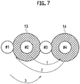
- the order of spraying the multiple cylinder bores 6A to 6D is set as described below, so as to avoid a sudden drop in cylinder block temperature after the pre-heating due to the exhaust ventilation. Specifically, the cylinder bore located while leaving a space of at least one cylinder from the cylinder bore first sprayed is sprayed next.
- the second cylinder bore 6B is first sprayed.
- the first cylinder bore 6A is indicated with #1
- the second cylinder bore 6B is indicated with #2
- the third cylinder bore 6C is indicated with #3
- the fourth cylinder bore 6D is indicated with #4, respectively.
- the spraying order is indicated with 1, 2, 3, and 4, respectively.
- the spray gun 2 is inserted deep into the second cylinder bore 6B from a cylinder head surface side thereof. Simultaneously, the molten metal droplets 11 are sprayed onto the inner surface of the cylinder bore.
- the sprayed coating 12 is formed by spraying and depositing the metal droplets 11 on the inner surface of the cylinder bore. During the spraying, residual particles, soot, or splattered droplets 11 that fail to adhere to the inner surface of the cylinder bore are discharged to the outside of the enclosure 3 through the exhaust ducts 5 by the exhaust ventilation. Thus, it is possible to avoid deterioration in quality of the sprayed coating 12.
- the fourth cylinder bore 6D located while leaving a space of one cylinder from the second cylinder bore 6B is sprayed.
- the adjacent third cylinder bore 6C is heated by the heat in the spraying.
- the first cylinder bore 6A located while leaving a space of two cylinders from the fourth cylinder bore 6D is sprayed.
- the first cylinder bore 6A is in the heated state by the heat input in the earlier spraying on the second cylinder bore 6C.
- a drop in in-bore temperature of the first cylinder bore 6A is suppressed.
- the third cylinder bore 6C located while leaving a space of one cylinder from the first cylinder bore 6A is sprayed.
- the third cylinder bore 6C is in the heated state by the heat input in the spraying on the fourth cylinder bore 6D and the heat input in the spraying on the second cylinder bore 6B.
- a drop in in-bore temperature of the third cylinder bore 6C is suppressed.
- the cylinder bore located while leaving the space of at least one cylinder from the cylinder bore first sprayed is sprayed.
- the cylinder bores located on two sides of the cylinder bore first sprayed are heated by the heat of the first spraying.
- the second cylinder bore 6B of the in-line four-cylinder engine is first sprayed, and then the fourth cylinder bore 6D, the first cylinder bore 6A, and the third cylinder bore 6C thereof are sprayed in this order.
- the pre-heating temperature of the cylinder block 1 that would otherwise gradually drop over time can be recovered by the heat input in the spraying on each cylinder bore.
- the sprayed coating forming method of this embodiment residual particles, soot, or splattered droplets that fail to adhere to the inner surfaces of the cylinder bores are discharged to the outside of the enclosure, which houses the cylinder block, by conducting the exhaust ventilation in the spraying.
- the exhaust ventilation in the spraying it is possible to suppress deterioration in quality of the sprayed coatings 12 and to control the coating thickness at the same time.
- the air supplied into the enclosure to house the cylinder block flows around the cylinder block and also flows inside the cylinder bores formed in the cylinder block.
- the present invention is not limited only to the above-described embodiment.
- the order of spraying is determined in the order of the second cylinder bore 6B, the fourth cylinder bore 6D, the first cylinder bore 6A, and the third cylinder bore 6C, the order is not limited only to the foregoing.
- the sprayed coatings 12 are formed in the in-line four-cylinder engine.
- the sprayed coating forming method of the present invention is also applicable to an in-line six-cylinder engine and a V-type engine.
- the exhaust ventilation may also be conducted from a head block attaching surface side of the cylinder bores 6.
Landscapes
- Engineering & Computer Science (AREA)
- Chemical & Material Sciences (AREA)
- Mechanical Engineering (AREA)
- Combustion & Propulsion (AREA)
- General Engineering & Computer Science (AREA)
- Plasma & Fusion (AREA)
- Chemical Kinetics & Catalysis (AREA)
- Materials Engineering (AREA)
- Physics & Mathematics (AREA)
- Metallurgy (AREA)
- Organic Chemistry (AREA)
- Coating By Spraying Or Casting (AREA)
- Cylinder Crankcases Of Internal Combustion Engines (AREA)
Abstract
Description
- The present invention relates to a sprayed coating forming method of forming a sprayed coating on an inner surface of a cylinder bore.
- Bore spraying is a method of forming a coating on an inner surface of a cylinder bore of a cylinder block for an automobile or the like by spraying a metal or a ceramic, then smoothing its surface by honing, and thereby forming a sliding surface for a piston ring. The bore spraying is applied as a technique for improving fuel efficiency.
- To improve adhesion of such a coating to a base material, a cylinder block is subjected to heating (this heating is called pre-heating) before spraying (see Non Patent Literature 1).
- [Non Patent Literature 1] Journal of the Japan Institute of Metals, Vol. 71, No. 3 (2007), 354-360
- In spraying, of droplets of a molten metal material, residual particles, soot, or splattered droplets that fail to adhere to a sprayed surface may be captured in a sprayed coating. To avoid this, the splattered droplets and the like are discharged to the outside of the cylinder block by conducting exhaust ventilation from a lower side of the cylinder block.
- However, the inner surface of the cylinder bore, i.e., the spray target surface is cooled by exhaust airflow that flows in and out of the cylinder block, and a pre-heating temperature of the cylinder block drops as a consequence. For this reason, the adhesion of the sprayed coating to the inner surface of the cylinder bore is deteriorated.
- In view of the above, the present invention provides a sprayed coating forming method which is capable of suppressing a drop in pre-heating temperature of a cylinder block and enhancing adhesion of a sprayed coating to an inner surface of a cylinder bore.
- According to a sprayed coating forming method of the present invention, a cylinder bore located while leaving a space of at least one cylinder from a cylinder bore first sprayed is sprayed next.
-
- [
Fig. 1] Fig. 1 is a perspective view showing the entirety of a sprayed coating formation apparatus for carrying out a method of an embodiment of the present invention. - [
Fig. 2] Fig. 2 is a diagram showing airflow when exhaust ventilation is conducted by the sprayed coating formation apparatus for carrying out the method of the embodiment. - [
Fig. 3] Fig. 3 is a perspective view showing a state before a spray gun is inserted into a cylinder bore. - [
Fig. 4] Fig. 4 is a schematic diagram showing an aspect of forming a sprayed coating by spraying droplets onto an inner surface of a cylinder bore. - [
Fig. 5] Fig. 5 is a characteristic chart showing a relation between a pre-heating temperature and adhesion. - [
Fig. 6] Fig. 6 is a characteristic chart showing changes in cylinder block temperature after pre-heating over time, which are observed in a first cylinder bore and a fourth cylinder bore. - [
Fig. 7] Fig. 7 is a diagram showing an order of spraying cylinder bores. - A specific embodiment applying the present invention will be described below in detail with reference to the drawings.
-
Fig. 1 is a perspective view showing the entirety of a sprayed coating formation apparatus for carrying out a sprayed coating forming method of this embodiment. The sprayed coating formation apparatus has a configuration in which acylinder block 1 and aspray gun 2 for forming a sprayed coating on an inner surface of each cylinder bore in thecylinder block 1 are disposed in anenclosure 3 for exhaust ventilation. - The
enclosure 3 is formed as a rectangular box having a shape of a hexahedron, for example. However, the shape of theenclosure 3 is not limited to the shape ofFig. 1 . WhenFig. 1 is viewed from the front, for example, anintake duct 4 for air intake is provided on aleft side surface 3a. Meanwhile,exhaust ducts 5 for exhaust ventilation are provided on aright side surface 3b, anupper surface 3c, and alower surface 3d. - Air to be supplied into the
enclosure 3 is introduced to theintake duct 4. The air inside theenclosure 3 is discharged from theexhaust ducts 5 to the outside of theenclosure 3. Of droplets of a molten metal material, residual particles, soot, or splattered droplets that fail to adhere to a sprayed surface are discharged from theseexhaust ducts 5 together with the air to be discharged. - The air supplied from the
intake duct 4 into theenclosure 3 flows as indicated with arrows inFig. 2 . The air flows around thecylinder block 1 and also flows inside cylinder bores 6 (6A, 6B, 6C, and 6D) formed in thecylinder block 1. - The
spray gun 2 is an arc spray gun as shown inFig. 3 and Fig. 4 . Thisarc spray gun 2 is configured to: poke out awire 7 which is made of a metal material and serving as a positive electrode and a wire 8 which is likewise made of the metal material and serving as a negative electrode, continuously in such a manner that thewires 7 and 8 are brought close to each other at a tip end of a nozzle; and generate anarc 10 by supplying anatomizing gas 9. Thewires 7 and 8 are melted by thisarc 10 and are formed intodroplets 11 which are sprayed particles. Thedroplets 11 adhere to aninner surface 6a of each cylinder bore 6, thereby forming a sprayedcoating 12. - It has been known that adhesion of the sprayed
coating 12 to be formed on theinner surface 6a of the cylinder bore 6 depends on a pre-heating temperature for heating thecylinder block 1 prior to the spraying. As shown inFig. 5 , as the pre-heating temperature of thecylinder block 1 becomes higher, the adhesion of the sprayedcoating 12 grows larger in accordance with the rise in the pre-heating temperature. - A sequence to form the coatings on the multiple cylinder bores 6A to 6D is important for forming the sprayed
coatings 12 by spraying themolten metal droplets 11 onto theinner surfaces 6a of the cylinder bores 6. Here, the cylinder bores 6 formed in thecylinder block 1 for an in-line four-cylinder engine are defined as afirst cylinder bore 6A, a second cylinder bore 6B, a third cylinder bore 6C, and a fourth cylinder bore 6D sequentially from one end, for example. - After this
cylinder block 1 is disposed in theenclosure 3, thecylinder block 1 is pre-heated by heating means such as a heater. Then, the inside of theenclosure 3 is subjected to exhaust ventilation. Hence, the airflow occurs as illustrated inFig. 2 . Next, as for the order of spraying, if thefirst cylinder bore 6A, thesecond cylinder bore 6B, the third cylinder bore 6C, and thefourth cylinder bore 6D are sprayed in this order from one end, thefourth cylinder bore 6D is continuously deprived of the pre-heat due to the exhaust airflow. For this reason, the cylinder bore later in the order of spraying is sprayed in the state deprived of more heat from the pre-heating temperature. -
Fig. 6 shows changes in cylinder block temperature after pre-heating over time, which are observed in thefirst cylinder bore 6A and thefourth cylinder bore 6D. InFig. 6 , a line 6At indicates the change in temperature of thefirst cylinder bore 6A while a line 6Dt indicates the change in temperature of thefourth cylinder bore 6D. In the meantime, X1 shows a point of the spraying on thefirst cylinder bore 6A while X2 shows a point of the spraying on thefourth cylinder bore 6D. As clear fromFig. 6 , regarding the fourth cylinder bore 6D to be sprayed at the end, its cylinder block temperature after pre-heating drops over time. For this reason, the sprayedcoating 12 on thefourth cylinder bore 6D is sprayed in the state of the temperature dropped substantially below the pre-heating temperature, whereby its adhesion is deteriorated as a consequence. - In this embodiment, the order of spraying the multiple cylinder bores 6A to 6D is set as described below, so as to avoid a sudden drop in cylinder block temperature after the pre-heating due to the exhaust ventilation. Specifically, the cylinder bore located while leaving a space of at least one cylinder from the cylinder bore first sprayed is sprayed next.
- To be more precise, as shown in
Fig. 7 , thesecond cylinder bore 6B is first sprayed. InFig. 7 , thefirst cylinder bore 6A is indicated with #1, thesecond cylinder bore 6B is indicated with #2, the third cylinder bore 6C is indicated with #3, and thefourth cylinder bore 6D is indicated with #4, respectively. Meanwhile, the spraying order is indicated with 1, 2, 3, and 4, respectively. - The
spray gun 2 is inserted deep into the second cylinder bore 6B from a cylinder head surface side thereof. Simultaneously, themolten metal droplets 11 are sprayed onto the inner surface of the cylinder bore. The sprayedcoating 12 is formed by spraying and depositing themetal droplets 11 on the inner surface of the cylinder bore. During the spraying, residual particles, soot, or splattereddroplets 11 that fail to adhere to the inner surface of the cylinder bore are discharged to the outside of theenclosure 3 through theexhaust ducts 5 by the exhaust ventilation. Thus, it is possible to avoid deterioration in quality of the sprayedcoating 12. - When the
second cylinder bore 6B is sprayed, the first cylinder bore 6A and the third cylinder bore 6C, which are the cylinder bores located on two sides, are heated by the heat in the spraying. InFig. 7 , shaded regions representheat input regions cylinder block 1 over time. - Next, the
fourth cylinder bore 6D located while leaving a space of one cylinder from thesecond cylinder bore 6B is sprayed. Hence, the adjacent third cylinder bore 6C is heated by the heat in the spraying. Subsequently, thefirst cylinder bore 6A located while leaving a space of two cylinders from thefourth cylinder bore 6D is sprayed. When thefirst cylinder bore 6A is sprayed, thefirst cylinder bore 6A is in the heated state by the heat input in the earlier spraying on the second cylinder bore 6C. Thus, a drop in in-bore temperature of thefirst cylinder bore 6A is suppressed. - And finally, the third cylinder bore 6C located while leaving a space of one cylinder from the
first cylinder bore 6A is sprayed. When the third cylinder bore 6C is sprayed, the third cylinder bore 6C is in the heated state by the heat input in the spraying on the fourth cylinder bore 6D and the heat input in the spraying on thesecond cylinder bore 6B. Thus, a drop in in-bore temperature of the third cylinder bore 6C is suppressed. - By performing the spraying on the cylinder bores 6A to 6D in the above-described order, it is possible to avoid a drop in temperature of the cylinder block after the pre-heating due to the exhaust ventilation, and to enhance the adhesion of the sprayed
coatings 12 formed on all the cylinder bores 6A to 6D. - According to the sprayed coating forming method of this embodiment, the cylinder bore located while leaving the space of at least one cylinder from the cylinder bore first sprayed is sprayed. Thus, the cylinder bores located on two sides of the cylinder bore first sprayed are heated by the heat of the first spraying. For this reason, by determining the cylinder located while leaving the space of at least one cylinder to be sprayed next, it is possible to suppress the drop in pre-heating temperature as compared to the case of spraying the cylinder bores sequentially from one end. As a consequence, according to the method of this embodiment, it is possible to enhance the adhesion of the sprayed
coatings 12 formed on the inner surfaces of the cylinder bores 6. - Meanwhile, according to the sprayed coating forming method of this embodiment, the second cylinder bore 6B of the in-line four-cylinder engine is first sprayed, and then the
fourth cylinder bore 6D, thefirst cylinder bore 6A, and the third cylinder bore 6C thereof are sprayed in this order. Thus, the pre-heating temperature of thecylinder block 1 that would otherwise gradually drop over time can be recovered by the heat input in the spraying on each cylinder bore. Thus, it is possible to suppress a sudden drop in temperature of the in-bore temperature of each of the cylinder bores 6A to 6D. - Moreover, according to the sprayed coating forming method of this embodiment, residual particles, soot, or splattered droplets that fail to adhere to the inner surfaces of the cylinder bores are discharged to the outside of the enclosure, which houses the cylinder block, by conducting the exhaust ventilation in the spraying. Thus, it is possible to suppress deterioration in quality of the sprayed
coatings 12 and to control the coating thickness at the same time. - Furthermore, according to the sprayed coating forming method of this embodiment, the air supplied into the enclosure to house the cylinder block flows around the cylinder block and also flows inside the cylinder bores formed in the cylinder block. As a consequence, it is possible to prevent residual particles and the like, which may scatter in the spraying, from adhering to the sprayed coatings.
- The entire contents of Japanese Patent Application No.
2014-038240 (date of filing: February 28, 2014 - Although a certain embodiment applying the present invention has been described above, the present invention is not limited only to the above-described embodiment. For example, while the order of spraying is determined in the order of the
second cylinder bore 6B, thefourth cylinder bore 6D, thefirst cylinder bore 6A, and the third cylinder bore 6C, the order is not limited only to the foregoing. Meanwhile, in the above-described embodiment, the sprayedcoatings 12 are formed in the in-line four-cylinder engine. However, the sprayed coating forming method of the present invention is also applicable to an in-line six-cylinder engine and a V-type engine. In the meantime, the exhaust ventilation may also be conducted from a head block attaching surface side of the cylinder bores 6. -
- 1
- cylinder block
- 2
- spray gun
- 3
- enclosure
- 6 (6A to 6D)
- cylinder bore
- 6a
- inner surface of cylinder bore
- 11
- droplet
- 12
- sprayed coating
Claims (4)
- A sprayed coating forming method of forming a sprayed coating, comprising the steps of:pre-heating a cylinder block defining a plurality of cylinders;inserting a spray gun sequentially into cylinder bores while conducting exhaust ventilation at least from one side of the cylinder block; andspraying droplets of a molten metal onto an inner surface of each cylinder bore, whereinthe cylinder bore located while leaving a space of at least one cylinder from the cylinder bore first sprayed is sprayed next.
- The sprayed coating forming method according to claim 1,
wherein
the four cylinder bores sequentially named a first cylinder bore, a second cylinder bore, a third cylinder bore, and a fourth cylinder bore are formed in series in the cylinder block, and
the second cylinder bore is first sprayed, and then the fourth cylinder bore, the first cylinder bore, and the third cylinder bore are sprayed in this order. - The sprayed coating forming method according to claim 1, wherein, in the spraying, any of residual particles, soot, and splattered droplets that fail to adhere to the inner surface of any of the cylinder bores are discharged to outside of an enclosure to house the cylinder block by conducting the exhaust ventilation.
- The sprayed coating forming method according to any one of claims 1 to 3, wherein air supplied into an enclosure to house the cylinder block flows around the cylinder block and also flows inside the cylinder bores formed in the cylinder block.
Applications Claiming Priority (2)
| Application Number | Priority Date | Filing Date | Title |
|---|---|---|---|
| JP2014038240 | 2014-02-28 | ||
| PCT/JP2015/051628 WO2015129347A1 (en) | 2014-02-28 | 2015-01-22 | Method for forming thermally sprayed coating |
Publications (2)
| Publication Number | Publication Date |
|---|---|
| EP3112494A1 true EP3112494A1 (en) | 2017-01-04 |
| EP3112494A4 EP3112494A4 (en) | 2017-03-08 |
Family
ID=54008676
Family Applications (1)
| Application Number | Title | Priority Date | Filing Date |
|---|---|---|---|
| EP15754635.9A Withdrawn EP3112494A4 (en) | 2014-02-28 | 2015-01-22 | Method for forming thermally sprayed coating |
Country Status (6)
| Country | Link |
|---|---|
| US (1) | US20160362776A1 (en) |
| EP (1) | EP3112494A4 (en) |
| JP (1) | JPWO2015129347A1 (en) |
| CN (1) | CN106029936A (en) |
| MX (1) | MX2016010816A (en) |
| WO (1) | WO2015129347A1 (en) |
Families Citing this family (2)
| Publication number | Priority date | Publication date | Assignee | Title |
|---|---|---|---|---|
| EP2799152B8 (en) * | 2013-05-03 | 2016-02-24 | Oerlikon Metco AG, Wohlen | Processing device for processing a workpiece surface |
| US20250051900A1 (en) * | 2022-03-31 | 2025-02-13 | Tocalo Co., Ltd. | Surface treatment method for ceramic thermal spray coating, and ceramic thermal spray coating |
Family Cites Families (12)
| Publication number | Priority date | Publication date | Assignee | Title |
|---|---|---|---|---|
| JPH11264341A (en) * | 1998-03-19 | 1999-09-28 | Suzuki Motor Corp | Thermal spraying method for multi-cylinder cylinder |
| DE10256460B4 (en) * | 2001-12-03 | 2006-10-26 | Nissan Motor Co., Ltd., Yokohama | Process for producing a product with a sprayed coating film and spray gun device |
| JP4051996B2 (en) * | 2002-05-02 | 2008-02-27 | 日産自動車株式会社 | Thermal spraying method on cylinder inner surface and cylinder block production method |
| JP2003171754A (en) * | 2001-12-03 | 2003-06-20 | Tocalo Co Ltd | Spraying method on inner surface of cylinder and cylinder block manufactured by this spraying method |
| JP3969289B2 (en) * | 2002-11-20 | 2007-09-05 | トヨタ自動車株式会社 | Thermal spraying equipment and thermal spraying method |
| JP2005272890A (en) * | 2004-03-23 | 2005-10-06 | Nissan Motor Co Ltd | Method for forming sprayed coating |
| JP2006257459A (en) * | 2005-03-15 | 2006-09-28 | Fuji Heavy Ind Ltd | Thermal spraying method and thermal spraying equipment |
| JP5029153B2 (en) * | 2007-06-08 | 2012-09-19 | 日産自動車株式会社 | Excess thermal spray coating removal method and apparatus, and liquid jet nozzle used in the apparatus |
| JP5504621B2 (en) * | 2008-02-29 | 2014-05-28 | 日産自動車株式会社 | Thermal spraying apparatus for cylinder bore and thermal spray film forming method |
| JP5401959B2 (en) * | 2008-12-10 | 2014-01-29 | 日産自動車株式会社 | Thermal spray masking apparatus and thermal spray film removing apparatus and thermal spray film removing method used in the same |
| JP5504648B2 (en) * | 2009-03-03 | 2014-05-28 | 日産自動車株式会社 | Thermal spraying apparatus and thermal spraying method |
| US9168547B2 (en) * | 2011-07-01 | 2015-10-27 | Comau, Inc. | Thermal metal spraying apparatus |
-
2015
- 2015-01-22 CN CN201580009271.6A patent/CN106029936A/en active Pending
- 2015-01-22 WO PCT/JP2015/051628 patent/WO2015129347A1/en not_active Ceased
- 2015-01-22 JP JP2016505104A patent/JPWO2015129347A1/en active Pending
- 2015-01-22 MX MX2016010816A patent/MX2016010816A/en unknown
- 2015-01-22 EP EP15754635.9A patent/EP3112494A4/en not_active Withdrawn
- 2015-01-22 US US15/121,664 patent/US20160362776A1/en not_active Abandoned
Also Published As
| Publication number | Publication date |
|---|---|
| MX2016010816A (en) | 2016-10-26 |
| CN106029936A (en) | 2016-10-12 |
| US20160362776A1 (en) | 2016-12-15 |
| WO2015129347A1 (en) | 2015-09-03 |
| JPWO2015129347A1 (en) | 2017-03-30 |
| EP3112494A4 (en) | 2017-03-08 |
Similar Documents
| Publication | Publication Date | Title |
|---|---|---|
| CN105431624B (en) | Method for producing an oxidation protection layer for a piston used in an internal combustion engine and piston having an oxidation protection layer | |
| US9976441B2 (en) | Article, component, and method of forming an article | |
| US20130055993A1 (en) | Cylinder liner with a thermal barrier coating | |
| EP3418420A3 (en) | Impurity barrier layer for ceramic matrix composite substrate | |
| CN104105843A (en) | Method for producing a near-surface cooling passage in a thermally highly stressed component, and component having such a passage | |
| EP4269653A3 (en) | Molding composite part with metal layer | |
| US10487677B2 (en) | Turbine component having a seal slot and additive manufacturing process for making same | |
| US8500907B2 (en) | Masking system for the masking of a cylinder bore | |
| US20160362776A1 (en) | Sprayed coating forming method | |
| CA2867101C (en) | Method of producing plug for piercing-rolling | |
| CN105143494B (en) | Wear-resistant piston ring coating | |
| US20160230698A1 (en) | Thermal spraying apparatus and thermal spraying method | |
| US6667460B2 (en) | Inner torch | |
| JP6846741B2 (en) | Insulation coating method for aluminum die-cast products | |
| CN103108987B (en) | Thermal coating method | |
| US10550461B2 (en) | Internal combustion engine and method for producing a crankcase and/or a cylinder liner for an internal combustion engine | |
| JP6319258B2 (en) | Engine insulation structure | |
| WO2015068519A1 (en) | Spray coating forming device and spray coating forming method | |
| CN106029935A (en) | Sliding arrangement and method for producing the sliding arrangement, in particular for a cylinder liner | |
| CN104919074A (en) | Processes and systems for depositing coating systems, and components coated therewith | |
| CN107013355A (en) | The bonded cylinder block insert of heat release | |
| EP2817436B1 (en) | Method for coating a substrate | |
| JP2018012875A (en) | Film deposition method of spray deposit | |
| RU2606774C2 (en) | Method for production of compact layer of enamel coating on cast articles | |
| JPH11264341A (en) | Thermal spraying method for multi-cylinder cylinder |
Legal Events
| Date | Code | Title | Description |
|---|---|---|---|
| PUAI | Public reference made under article 153(3) epc to a published international application that has entered the european phase |
Free format text: ORIGINAL CODE: 0009012 |
|
| STAA | Information on the status of an ep patent application or granted ep patent |
Free format text: STATUS: REQUEST FOR EXAMINATION WAS MADE |
|
| 17P | Request for examination filed |
Effective date: 20160923 |
|
| AK | Designated contracting states |
Kind code of ref document: A1 Designated state(s): AL AT BE BG CH CY CZ DE DK EE ES FI FR GB GR HR HU IE IS IT LI LT LU LV MC MK MT NL NO PL PT RO RS SE SI SK SM TR |
|
| AX | Request for extension of the european patent |
Extension state: BA ME |
|
| A4 | Supplementary search report drawn up and despatched |
Effective date: 20170208 |
|
| RIC1 | Information provided on ipc code assigned before grant |
Ipc: C23C 4/12 20160101AFI20170202BHEP Ipc: F02F 1/00 20060101ALI20170202BHEP |
|
| DAX | Request for extension of the european patent (deleted) | ||
| STAA | Information on the status of an ep patent application or granted ep patent |
Free format text: STATUS: EXAMINATION IS IN PROGRESS |
|
| 17Q | First examination report despatched |
Effective date: 20171005 |
|
| GRAP | Despatch of communication of intention to grant a patent |
Free format text: ORIGINAL CODE: EPIDOSNIGR1 |
|
| STAA | Information on the status of an ep patent application or granted ep patent |
Free format text: STATUS: GRANT OF PATENT IS INTENDED |
|
| RIC1 | Information provided on ipc code assigned before grant |
Ipc: C23C 4/12 20160101AFI20180223BHEP Ipc: F02F 7/00 20060101ALI20180223BHEP Ipc: F02F 1/00 20060101ALI20180223BHEP |
|
| INTG | Intention to grant announced |
Effective date: 20180313 |
|
| STAA | Information on the status of an ep patent application or granted ep patent |
Free format text: STATUS: THE APPLICATION IS DEEMED TO BE WITHDRAWN |
|
| 18D | Application deemed to be withdrawn |
Effective date: 20180724 |