EP3112258A1 - Airfoils for rotor blades of rotary wing aircrafts - Google Patents
Airfoils for rotor blades of rotary wing aircrafts Download PDFInfo
- Publication number
- EP3112258A1 EP3112258A1 EP15400028.5A EP15400028A EP3112258A1 EP 3112258 A1 EP3112258 A1 EP 3112258A1 EP 15400028 A EP15400028 A EP 15400028A EP 3112258 A1 EP3112258 A1 EP 3112258A1
- Authority
- EP
- European Patent Office
- Prior art keywords
- airfoil
- extrados
- intrados
- coordinate value
- value pairs
- Prior art date
- Legal status (The legal status is an assumption and is not a legal conclusion. Google has not performed a legal analysis and makes no representation as to the accuracy of the status listed.)
- Granted
Links
- 238000010586 diagram Methods 0.000 description 15
- 238000011084 recovery Methods 0.000 description 3
- 230000035939 shock Effects 0.000 description 3
- 238000012986 modification Methods 0.000 description 2
- 230000004048 modification Effects 0.000 description 2
- 230000002349 favourable effect Effects 0.000 description 1
- 238000005259 measurement Methods 0.000 description 1
- 238000004088 simulation Methods 0.000 description 1
- 230000003068 static effect Effects 0.000 description 1
Images


Classifications
-
- B—PERFORMING OPERATIONS; TRANSPORTING
- B64—AIRCRAFT; AVIATION; COSMONAUTICS
- B64C—AEROPLANES; HELICOPTERS
- B64C3/00—Wings
- B64C3/10—Shape of wings
- B64C3/14—Aerofoil profile
-
- B—PERFORMING OPERATIONS; TRANSPORTING
- B64—AIRCRAFT; AVIATION; COSMONAUTICS
- B64C—AEROPLANES; HELICOPTERS
- B64C27/00—Rotorcraft; Rotors peculiar thereto
- B64C27/32—Rotors
- B64C27/46—Blades
- B64C27/467—Aerodynamic features
-
- F—MECHANICAL ENGINEERING; LIGHTING; HEATING; WEAPONS; BLASTING
- F04—POSITIVE - DISPLACEMENT MACHINES FOR LIQUIDS; PUMPS FOR LIQUIDS OR ELASTIC FLUIDS
- F04D—NON-POSITIVE-DISPLACEMENT PUMPS
- F04D29/00—Details, component parts, or accessories
- F04D29/18—Rotors
- F04D29/181—Axial flow rotors
-
- F—MECHANICAL ENGINEERING; LIGHTING; HEATING; WEAPONS; BLASTING
- F04—POSITIVE - DISPLACEMENT MACHINES FOR LIQUIDS; PUMPS FOR LIQUIDS OR ELASTIC FLUIDS
- F04D—NON-POSITIVE-DISPLACEMENT PUMPS
- F04D29/00—Details, component parts, or accessories
- F04D29/26—Rotors specially for elastic fluids
- F04D29/32—Rotors specially for elastic fluids for axial flow pumps
- F04D29/38—Blades
- F04D29/384—Blades characterised by form
-
- Y—GENERAL TAGGING OF NEW TECHNOLOGICAL DEVELOPMENTS; GENERAL TAGGING OF CROSS-SECTIONAL TECHNOLOGIES SPANNING OVER SEVERAL SECTIONS OF THE IPC; TECHNICAL SUBJECTS COVERED BY FORMER USPC CROSS-REFERENCE ART COLLECTIONS [XRACs] AND DIGESTS
- Y02—TECHNOLOGIES OR APPLICATIONS FOR MITIGATION OR ADAPTATION AGAINST CLIMATE CHANGE
- Y02T—CLIMATE CHANGE MITIGATION TECHNOLOGIES RELATED TO TRANSPORTATION
- Y02T50/00—Aeronautics or air transport
- Y02T50/30—Wing lift efficiency
-
- Y—GENERAL TAGGING OF NEW TECHNOLOGICAL DEVELOPMENTS; GENERAL TAGGING OF CROSS-SECTIONAL TECHNOLOGIES SPANNING OVER SEVERAL SECTIONS OF THE IPC; TECHNICAL SUBJECTS COVERED BY FORMER USPC CROSS-REFERENCE ART COLLECTIONS [XRACs] AND DIGESTS
- Y02—TECHNOLOGIES OR APPLICATIONS FOR MITIGATION OR ADAPTATION AGAINST CLIMATE CHANGE
- Y02T—CLIMATE CHANGE MITIGATION TECHNOLOGIES RELATED TO TRANSPORTATION
- Y02T50/00—Aeronautics or air transport
- Y02T50/60—Efficient propulsion technologies, e.g. for aircraft
Definitions
- the invention is related to an airfoil for a rotor blade of a rotary wing aircraft, said airfoil having a predetermined maximum thickness to chord ratio and comprising the features of claims 1, 6 or 11.
- the invention is further related to a rotor blade of a rotary wing aircraft, said rotor blade comprising the features of claim 16.
- Airfoils for rotor blades of rotary wing aircrafts are generally characterized by an extrados and an intrados that are arranged between corresponding leading and trailing edges of the airfoils and that are defined by predetermined intrados coordinate value pairs x/c, y int /c and predetermined extrados coordinate value pairs x/c, y ext /c.
- x is a distance from a leading edge to a trailing edge along a chord line of the airfoil
- c is a length of the airfoil in chord direction
- y int is a distance between the chord line and a respective intrados surface
- y ext is a distance between the chord line and a respective extrados surface.
- the airfoils are usually further characterized by associated predetermined maximum thickness to chord ratios, as well as by leading edge radiuses r/c of corresponding leading edge circles and their center positions x/c and y int /c or y ext /c.
- an object of the present invention to provide a new airfoil for a rotor blade of a rotary wing aircraft, said airfoil providing for a reduced aerodynamic drag, an improved maximum lift capacity and improved hover and forward flight performances of said rotor blade. It is a further object of the present invention to provide a new rotor blade having an airfoil that provides for a reduced aerodynamic drag, an improved maximum lift capacity and improved hover and forward flight performances.
- This object is solved by an airfoil for a rotor blade of a rotary wing aircraft, said airfoil having a maximum thickness to chord ratio of 12% and comprising the features of claim 1.
- This object is also solved by an airfoil for a rotor blade of a rotary wing aircraft, said airfoil having a maximum thickness to chord ratio of 9% and comprising the features of claim 6.
- This object is further solved by an airfoil for a rotor blade of a rotary wing aircraft, said airfoil having a maximum thickness to chord ratio of 8% and comprising the features of claim 11.
- these inventive airfoils exhibit a reduced aerodynamic drag by means of extended laminarity. Furthermore, an underlying maximum lift capacity is improved. Moreover, more negative, i. e. nose-down, static pitching moments around the quarter-chord of the airfoils due to the applied modifications to the camber line are acceptable, since dynamic loads as seen in numerical simulations and wind tunnel measurements prove to remain within those of prior art airfoils.
- the inventive airfoils exhibit reduced aerodynamic drag compared to prior art airfoils due to extended laminar running lengths on the upper side, i. e. the extrados. This is achieved by an improved leading edge geometry and by introducing a well-defined main pressure recovery at a downstream position, i. e. towards the trailing edge of the airfoil. These measures further enable the reduction of suction peaks and thereby allow for higher maximum lift coefficients at moderate Mach numbers as well as the reduction of transonic shocks at high lift coefficients. Furthermore, the application of the inventive airfoils provides for improved hover and forward flight performances of a given rotor of a rotary wing aircraft.
- At least one of the inventive airfoils are applied to a single rotor blade of a given rotary wing aircraft.
- a single rotor blade is provided with differing geometric shapes at different locations over its radial extension. Areas between these different locations are preferably provided with geometric shapes that result from interpolations between corresponding adjacent airfoils.
- an airfoil for a rotor blade of a rotary wing aircraft that has a maximum thickness to chord ratio of 12% comprises, between a leading edge and a trailing edge, an extrados and an intrados.
- the intrados is defined by predetermined intrados coordinate value pairs x/c, y int /c and the extrados is defined by predetermined extrados coordinate value pairs x/c, y ext /c.
- x is a distance from the leading edge to the trailing edge along a chord line of the airfoil
- c is a length of the airfoil in chord direction
- y int is a distance between the chord line and a respective intrados surface
- y ext is a distance between the chord line and a respective extrados surface.
- a maximum error of each one of the predetermined intrados coordinate value pairs x/c, y int /c and the predetermined extrados coordinate value pairs x/c, y ext /c preferentially amounts to ⁇ 3%.
- an airfoil for a rotor blade of a rotary wing aircraft with a maximum thickness to chord ratio within a range from 9% to 15% comprises intrados coordinate value pairs and extrados coordinate value pairs, which are determined on the basis of a reference airfoil that is defined by the airfoil having the maximum thickness to chord ratio of 12% as described above.
- a trailing edge tab is provided at the trailing edge of the airfoil.
- the trailing edge tab is defined by an at least essentially straight and parallel intrados and extrados.
- the trailing edge tab comprises a length in a range from 2% to 10% of the length of the airfoil in chord direction with a maximum inclination error of ⁇ 5° relative to the chord line of the airfoil.
- an airfoil for a rotor blade of a rotary wing aircraft that has a maximum thickness to chord ratio of 9% comprises, between a leading edge and a trailing edge, an extrados and an intrados.
- the intrados is defined by predetermined intrados coordinate value pairs x/c, y int /c and the extrados is defined by predetermined extrados coordinate value pairs x/c, y ext /c.
- x is a distance from the leading edge to the trailing edge along a chord line of the airfoil
- c is a length of the airfoil in chord direction
- y int is a distance between the chord line and a respective intrados surface
- y ext is a distance between the chord line and a respective extrados surface.
- a maximum error of each one of the predetermined intrados coordinate value pairs x/c, y int /c and the predetermined extrados coordinate value pairs x/c, y ext /c preferentially amounts to ⁇ 3%.
- an airfoil for a rotor blade of a rotary wing aircraft with a maximum thickness to chord ratio within a range from 7% to 12% comprises intrados coordinate value pairs and extrados coordinate value pairs, which are determined on the basis of a reference airfoil that is defined by the airfoil having the maximum thickness to chord ratio of 9% as described above.
- a trailing edge tab is provided at the trailing edge of the airfoil.
- the trailing edge tab is defined by an at least essentially straight and parallel intrados and extrados.
- the trailing edge tab comprises a length in a range from 2% to 10% of the length of the airfoil in chord direction with a maximum inclination error of ⁇ 5° relative to the chord line of the airfoil.
- an airfoil for a rotor blade of a rotary wing aircraft that has a maximum thickness to chord ratio of 8% comprises, between a leading edge and a trailing edge, an extrados and an intrados.
- the intrados is defined by predetermined intrados coordinate value pairs x/c, y int /c and the extrados is defined by predetermined extrados coordinate value pairs x/c, y ext /c.
- x is a distance from the leading edge to the trailing edge along a chord line of the airfoil
- c is a length of the airfoil in chord direction
- y int is a distance between the chord line and a respective intrados surface
- y ext is a distance between the chord line and a respective extrados surface.
- a maximum error of each one of the predetermined intrados coordinate value pairs x/c, y int /c and the predetermined extrados coordinate value pairs x/c, y ext /c preferentially amounts to ⁇ 3%.
- an airfoil for a rotor blade of a rotary wing aircraft with a maximum thickness to chord ratio within a range from 6% to 10% comprises intrados coordinate value pairs and extrados coordinate value pairs, which are determined on the basis of a reference airfoil that is defined by the airfoil having the maximum thickness to chord ratio of 8% as described above.
- a trailing edge tab is provided at the trailing edge of the airfoil.
- the trailing edge tab is defined by an at least essentially straight and parallel intrados and extrados.
- the trailing edge tab comprises a length in a range from 2% to 10% of the length of the airfoil in chord direction with a maximum inclination error of ⁇ 5° relative to the chord line of the airfoil.
- a rotor blade of a rotary wing aircraft that comprises at least one of the above-described airfoils.
- new rotor blades and in particular new main rotor blades can be manufactured that allow for an improvement of an overall performance of a main rotor of a rotary wing aircraft, in particular of a helicopter, while maintaining favorable unsteady characteristics thereof, such as dynamic stall.
- new main rotor blades can be provided with a particular geometric shape by application of the inventive airfoils at specific radial positions along these main rotor blades.
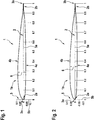
- Figure 1 shows a rotor blade 1 of a rotary wing aircraft that is provided with an airfoil 1a according to a first aspect of the present invention.
- the airfoil 1a preferably comprises a maximum thickness to chord ratio of 12%.
- the airfoil 1a comprises a leading edge 3a and a trailing edge 3b, which are illustratively arranged on an airfoil chord line 2 of the airfoil 1a.
- the airfoil 1a illustratively further comprises an intrados 4a and an extrados 4b that extend between the leading edge 3a and the trailing edge 3b.
- the intrados 4a is defined by predetermined intrados coordinate value pairs x/c, y int /c and the extrados 4b is defined by predetermined extrados coordinate value pairs x/c, y ext /c.
- x is a distance from the leading edge 3a to the trailing edge 3b along the chord line 2
- c is a length of the airfoil 1a in chord direction
- y int is a distance between the chord line 2 and a respective intrados surface
- y ext is a distance between the chord line 2 and a respective extrados surface.
- the predetermined intrados coordinate value pairs x/c, y int /c and the predetermined extrados coordinate value pairs x/c, y ext /c of the airfoil 1a that comprises a maximum thickness to chord ratio of 12% are defined according to Table 1 above.
- a maximum error of each one of these predetermined intrados coordinate value pairs x/c, y int /c and these predetermined extrados coordinate value pairs x/c, y ext /c amounts to ⁇ 3%.
- the predetermined intrados coordinate value pairs x/c, y int /c and the predetermined extrados coordinate value pairs x/c, y ext /c of the airfoil 1a are determined in the region of the leading edge 3a on the basis of an associated leading edge circle 2a that, thus, defines an underlying curvature of the airfoil 1 a at the leading edge 3a.
- a maximum error of each one of the above described leading edge circle dimensions amounts to ⁇ 5%. This likewise applies to all leading edge circle dimensions that are described in the present patent application.
- the trailing edge 3b is provided with an associated trailing edge tab 2b.
- the latter is preferentially defined by an at least essentially straight and parallel intrados 4a and extrados 4b.
- the trailing edge tab 2b comprises a length in a range from 2% to 10% of the length of the airfoil 1a in chord direction with a maximum inclination error of ⁇ 5° relative to the chord line 2 of the airfoil 1a.
- Table 1 above is illustrated by way of example with respect to the airfoil 1a having a maximum thickness to chord ratio of 12%.
- this airfoil 1a and, consequently Table 1 may also be used as a reference for defining other airfoils for rotor blades of rotary wing aircrafts with other maximum thickness to chord ratios.
- the airfoil 1 a is used as a reference airfoil for determining intrados coordinate value pairs and extrados coordinate value pairs for an airfoil that comprises a maximum thickness to chord ratio within a range from 9% to 15%.
- at this location x/c 0.284 according to Table 1 through the length c of the airfoil 1 a in chord direction.
- defines approximately 28,5% of the maximum thickness and
- at this location x/c 0.284 according to Table 1 divided through the length c of the airfoil 1a in chord direction amounts to 15%, wherein
- Such a rescaling is then correspondingly applied to all other values of Table 1 for obtaining an airfoil with the maximum thickness to chord ratio of 15%.
- FIG. 2 shows the rotor blade 1 of Figure 1 that is now provided with an airfoil 1b according to a second aspect of the present invention, instead of the airfoil 1 a of Figure 1 .
- an airfoil 1b according to a second aspect of the present invention, instead of the airfoil 1 a of Figure 1 .
- the airfoil 1 b preferably comprises a maximum thickness to chord ratio of 9% and the predetermined intrados coordinate value pairs x/c, y int /c and the predetermined extrados coordinate value pairs x/c, y ext /c of the airfoil 1b are defined according to Table 2 above, with c now being a length of the airfoil 1 b in chord direction.
- Table 2 above is illustrated by way of example with respect to the airfoil 1b having a maximum thickness to chord ratio of 9%.
- this airfoil 1b and, consequently Table 2 may also be used as a reference for defining other airfoils for rotor blades of rotary wing aircrafts with other maximum thickness to chord ratios.
- the airfoil 1 b is used as a reference airfoil for determining intrados coordinate value pairs and extrados coordinate value pairs for an airfoil that comprises a maximum thickness to chord ratio within a range from 7% to 12%.
- FIG 3 shows the rotor blade 1 of Figure 1 that is now provided with an airfoil 1c according to a third aspect of the present invention, instead of the airfoil 1a of Figure 1 .
- an airfoil 1c according to a third aspect of the present invention, instead of the airfoil 1a of Figure 1 .
- the airfoil 1c preferably comprises a maximum thickness to chord ratio of 8% and the predetermined intrados coordinate value pairs x/c, y int /c and the predetermined extrados coordinate value pairs x/c, y ext /c of the airfoil 1 b are defined according to Table 3 above, with c now being a length of the airfoil 1c in chord direction.
- Table 3 above is illustrated by way of example with respect to the airfoil 1c having a maximum thickness to chord ratio of 8%.
- this airfoil 1c and, consequently Table 3 may also be used as a reference for defining other airfoils for rotor blades of rotary wing aircrafts with other maximum thickness to chord ratios.
- the airfoil 1 c is used as a reference airfoil for determining intrados coordinate value pairs and extrados coordinate value pairs for an airfoil that comprises a maximum thickness to chord ratio within a range from 6% to 10%.
- inventive airfoils according to Figure 1 to Figure 3 above are compared to conventional airfoils.
- the airfoils with maximum thickness to chord ratios of 12% and 9% according to tables 3 and 5, respectively, of the document US 6,361,279 B1 are selected as the conventional airfoils.
- Figure 4 shows a maximum lift coefficient diagram 7 with maximum lift coefficients C i,max outlined on a maximum lift coefficient axis 7b, which are plotted over Mach numbers outlined on a Mach number axis 7a.
- the maximum lift coefficient diagram 7 illustrates three exemplary rotor blade airfoil characteristic curves 8a, 9a, 10a for demonstrating maximum lift coefficients that can be obtained in operation when applying the airfoils 1a, 1 b, 1c of Figure 1 to Figure 3 .
- the characteristic curve 8a illustrates maximum lift coefficients of the 12% airfoil 1a of Figure 1
- the characteristic curve 9a illustrates maximum lift coefficients of the 9% airfoil 1b of Figure 2
- the characteristic curve 10a illustrates maximum lift coefficients of the 8% airfoil 1c of Figure 3 .
- the maximum lift coefficient diagram 7 further illustrates two exemplary rotor blade airfoil characteristic curves 8b, 9b for demonstrating maximum lift coefficients that can be obtained in operation when applying conventional airfoils. More specifically, the characteristic curve 8b illustrates maximum lift coefficients of a conventional 12% airfoil and the characteristic curve 9b illustrates maximum lift coefficients of a conventional 9% airfoil.
- Figure 4 is intended to allow a comparison between the characteristic curves 8a and 8b as well as 9a and 9b.
- higher maximum lift coefficients can be obtained with the 12% airfoil 1 a of Figure 1 and the 9% airfoil 1 b of Figure 2 , than with the corresponding conventional airfoils in the illustrated Mach number range from 0.3 to 0.6 for the 12% airfoil, respectively 0.4 to 0.6 for the 9% airfoil.
- the 8% airfoil 1c of Figure 3 allows to achieve higher maximum lift coefficients in the illustrated Mach number range from 0.4 to 0.6 than those that are obtained with the conventional 9% airfoil, as can be seen from a comparison of the characteristic curves 10a and 9b.
- Figure 5 shows a maximum lift to drag ratio diagram 11 with maximum lift to drag ratios L/D max outlined on a maximum lift to drag ratio axis 11b, which are plotted over Mach numbers outlined on a Mach number axis 11a.
- the maximum lift to drag ratio diagram 11 illustrates three exemplary rotor blade airfoil characteristic curves 12a, 13a, 14a for demonstrating maximum lift to drag ratios that can be obtained in operation when applying the airfoils 1 a, 1 b, 1c of Figure 1 to Figure 3 .
- the characteristic curve 12a illustrates maximum lift to drag ratios of the 12% airfoil 1a of Figure 1
- the characteristic curve 13a illustrates maximum lift to drag ratios of the 9% airfoil 1b of Figure 2
- the characteristic curve 14a illustrates maximum lift to drag ratios of the 8% airfoil 1 c of Figure 3 .
- the maximum lift to drag ratio diagram 11 further illustrates two exemplary rotor blade airfoil characteristic curves 12b, 13b for demonstrating maximum lift to drag ratios that can be obtained in operation when applying conventional airfoils. More specifically, the characteristic curve 12b illustrates maximum lift to drag ratios of a conventional 12% airfoil and the characteristic curve 13b illustrates maximum lift to drag ratios of a conventional 9% airfoil.
- Figure 5 is intended to allow a comparison between the characteristic curves 12a and 12b as well as 13a and 13b.
- higher maximum lift to drag ratios can be obtained with the 12% airfoil 1a of Figure 1 and the 9% airfoil 1 b of Figure 2 , than with the corresponding conventional airfoils in the illustrated Mach number range from 0.3 to 0.6.
- even the 8% airfoil 1c of Figure 3 allows to achieve higher maximum lift to drag ratios in the illustrated Mach number range from 0.3 to 0.6, except for the Mach number 0.5, than those that are obtained with the conventional 9% airfoil, as can be seen from a comparison of the characteristic curves 14a and 13b.
- Figure 6 shows a pressure coefficient diagram 15 with pressure coefficients C p outlined on a pressure coefficient axis 15b, which are plotted over an underlying chord length outlined on a chord axis 15a.
- the pressure coefficient diagram 15 illustrates two exemplary rotor blade airfoil characteristic curves 16a, 16c for demonstrating pressure coefficients that can be obtained in operation when applying the airfoil 1 b of Figure 2 . More specifically, the characteristic curve 16a illustrates pressure coefficients obtained at the extrados 4b of the 9% airfoil 1 b of Figure 2 and the characteristic curve 16c illustrates pressure coefficients obtained at the intrados 4a of the 9% airfoil 1b. of Figure 2 .
- the pressure coefficient diagram 15 further illustrates two exemplary rotor blade airfoil characteristic curves 16b, 16d for demonstrating pressure coefficients that can be obtained in operation when applying conventional airfoils. More specifically, the characteristic curve 16b illustrates pressure coefficients obtained at the extrados of a conventional 9% airfoil and the characteristic curve 16d illustrates pressure coefficients obtained at the intrados of a conventional 9% airfoil.
- Figure 6 is intended to allow a comparison between the characteristic curves 16a and 16b as well as 16c and 16d.
- suction peaks 17b on the extrados 4b of the 9% airfoil 1 b of Figure 2 are significantly smaller than on the extrados of the conventional 9% airfoil, thereby allowing for higher maximum lift coefficients at moderate Mach numbers, as illustrated in Figure 4 , and further allowing the reduction of transonic shocks at high lift coefficients.
- a geometrically defined main pressure recovery 17a is introduced at a downstream position of the extrados 4b of the 9% airfoil 1 b of Figure 2 compared to the conventional 9% airfoil, thus allowing for a reduced aerodynamic drag due to an extended laminar running length on the extrados 4b of the 9% airfoil 1b of Figure 2 .
- Figure 7 shows a rotor figure of merit 18 with figure of merit values FM outlined on a figure of merit axis 18b, which are plotted over blade loading values C T / ⁇ outlined on a blade loading axis 18a.
- the rotor figure of merit 18 illustrates an exemplary rotor blade characteristic curve 19a for demonstrating figure of merit values that can be obtained in operation when applying the 12% airfoil 1a of Figure 1 and the 9% airfoil 1b of Figure 2 in a single rotor blade, e. g. the rotor blade 1 of Figure 1 and Figure 2 .
- the rotor figure of merit 18 further illustrates an exemplary rotor blade characteristic curve 19b for demonstrating figure of merit values that can be obtained in operation when applying conventional 9% and 12% airfoils in a single rotor blade.
- the single rotor blade with the 12% airfoil 1a of Figure 1 and the 9% airfoil 1 b of Figure 2 can further be improved according to one aspect of the present invention by applying the 8% airfoil 1c of Figure 3 in a corresponding blade tip region thereof in order to alleviate transonic shocks at a respectively advancing blade side of the single rotor blade in operation in case of high speed forward flight.
- the rotor blade 1 of a rotary wing aircraft is respectively provided with one of the airfoils 1 a, 1b, 1 c.
- the rotor blade 1 may likewise be provided with two of the airfoils 1 a, 1 b, 1 c, as well as all three airfoils 1 a, 1 b, 1 c, as described above with respect to Figure 7 .
Abstract
Description
- The invention is related to an airfoil for a rotor blade of a rotary wing aircraft, said airfoil having a predetermined maximum thickness to chord ratio and comprising the features of
claims 1, 6 or 11. The invention is further related to a rotor blade of a rotary wing aircraft, said rotor blade comprising the features of claim 16. - Airfoils for rotor blades of rotary wing aircrafts are generally characterized by an extrados and an intrados that are arranged between corresponding leading and trailing edges of the airfoils and that are defined by predetermined intrados coordinate value pairs x/c, yint/c and predetermined extrados coordinate value pairs x/c, yext/c. Therein, x is a distance from a leading edge to a trailing edge along a chord line of the airfoil, c is a length of the airfoil in chord direction, yint is a distance between the chord line and a respective intrados surface and yext is a distance between the chord line and a respective extrados surface. The airfoils are usually further characterized by associated predetermined maximum thickness to chord ratios, as well as by leading edge radiuses r/c of corresponding leading edge circles and their center positions x/c and yint/c or yext/c.
- The documents
US 5,957,662 A andUS 6,315,522 B1 describe such airfoils and illustrate exemplary tables of values that comprise values for predetermined intrados coordinate value pairs x/c, yint/c and predetermined extrados coordinate value pairs x/c, yext/c. More specifically, the documentUS 5,957,662 A describes an airfoil with a maximum thickness to chord ratio of 8%, a leading edge radius r/c = 0.00844 and corresponding leading edge circle center positions x/c = 0.00842 and yext/c = 0.00064. The documentUS 6,315,522 B1 describes an airfoil with a maximum thickness to chord ratio of 10%, a leading edge radius r/c = 0.0096 and corresponding leading edge circle center positions x/c = 0.0097 and yint/c = -0.0018. - Furthermore, the document
US 6,361,279 B1 describes airfoils with maximum thickness to chord ratios of 12% (Table 3) and 9% (Table 5). Nevertheless, for these airfoils no leading edge radiuses r/c of corresponding leading edge circles and their center positions x/c and yint/c or yext/c are indicated. Instead, maximum camber positions and ratios of maximal camber to maximal thickness are used for further characterizing these airfoils. - However, these airfoils only provide for a restricted maximum lift capacity and a comparatively high aerodynamic drag. Furthermore, they only provide for restricted hover and forward flight performances.
- It is, therefore, an object of the present invention to provide a new airfoil for a rotor blade of a rotary wing aircraft, said airfoil providing for a reduced aerodynamic drag, an improved maximum lift capacity and improved hover and forward flight performances of said rotor blade. It is a further object of the present invention to provide a new rotor blade having an airfoil that provides for a reduced aerodynamic drag, an improved maximum lift capacity and improved hover and forward flight performances.
- This object is solved by an airfoil for a rotor blade of a rotary wing aircraft, said airfoil having a maximum thickness to chord ratio of 12% and comprising the features of claim 1. This object is also solved by an airfoil for a rotor blade of a rotary wing aircraft, said airfoil having a maximum thickness to chord ratio of 9% and comprising the features of claim 6. This object is further solved by an airfoil for a rotor blade of a rotary wing aircraft, said airfoil having a maximum thickness to chord ratio of 8% and comprising the features of
claim 11. - Advantageously, these inventive airfoils exhibit a reduced aerodynamic drag by means of extended laminarity. Furthermore, an underlying maximum lift capacity is improved. Moreover, more negative, i. e. nose-down, static pitching moments around the quarter-chord of the airfoils due to the applied modifications to the camber line are acceptable, since dynamic loads as seen in numerical simulations and wind tunnel measurements prove to remain within those of prior art airfoils.
- More specifically, the inventive airfoils exhibit reduced aerodynamic drag compared to prior art airfoils due to extended laminar running lengths on the upper side, i. e. the extrados. This is achieved by an improved leading edge geometry and by introducing a well-defined main pressure recovery at a downstream position, i. e. towards the trailing edge of the airfoil. These measures further enable the reduction of suction peaks and thereby allow for higher maximum lift coefficients at moderate Mach numbers as well as the reduction of transonic shocks at high lift coefficients. Furthermore, the application of the inventive airfoils provides for improved hover and forward flight performances of a given rotor of a rotary wing aircraft.
- Preferably, at least one of the inventive airfoils, more preferably at least two of the inventive airfoils and, preferentially, all inventive airfoils are applied to a single rotor blade of a given rotary wing aircraft. In other words, such a single rotor blade is provided with differing geometric shapes at different locations over its radial extension. Areas between these different locations are preferably provided with geometric shapes that result from interpolations between corresponding adjacent airfoils.
- More specifically, according to one aspect of the present invention an airfoil for a rotor blade of a rotary wing aircraft that has a maximum thickness to chord ratio of 12% comprises, between a leading edge and a trailing edge, an extrados and an intrados. The intrados is defined by predetermined intrados coordinate value pairs x/c, yint/c and the extrados is defined by predetermined extrados coordinate value pairs x/c, yext/c. Therein, x is a distance from the leading edge to the trailing edge along a chord line of the airfoil, c is a length of the airfoil in chord direction, yint is a distance between the chord line and a respective intrados surface and yext is a distance between the chord line and a respective extrados surface. The predetermined intrados coordinate value pairs x/c, yint/c and the predetermined extrados coordinate value pairs x/c, yext/c are defined according to Table 1 below.
TABLE 1: x/c yint/c x/c yext/c 0.000000 0.000000 0.000000 0.000000 0.000077 -0.001398 0.000077 0.001446 0.000307 -0.002749 0.000306 0.002940 0.000690 -0.004055 0.000689 0.004483 0.001226 -0.005315 0.001226 0.006071 0.001915 -0.006532 0.001914 0.007707 0.002756 -0.007707 0.002756 0.009385 0.003750 -0.008838 0.003750 0.011105 0.004897 -0.009926 0.004896 0.012865 0.006195 -0.010971 0.006194 0.014662 0.007644 -0.011971 0.007644 0.016492 0.009245 -0.012928 0.009244 0.018354 0.010996 -0.013840 0.010995 0.020243 0.012897 -0.014710 0.012896 0.022155 0.014947 -0.015537 0.014947 0.024087 0.017146 -0.016325 0.017146 0.026035 0.019494 -0.017076 0.019494 0.027995 0.021989 -0.017793 0.021989 0.029962 0.024631 -0.018478 0.024630 0.031932 0.027418 -0.019136 0.027418 0.033902 0.030351 -0.019769 0.030351 0.035867 0.033429 -0.020380 0.033428 0.037823 0.036649 -0.020971 0.036649 0.039766 0.040012 -0.021544 0.040012 0.041694 0.043517 -0.022102 0.043517 0.043603 0.047162 -0.022644 0.047162 0.045489 0.050946 -0.023172 0.050946 0.047350 0.054869 -0.023685 0.054868 0.049183 0.058929 -0.024185 0.058928 0.050985 0.063124 -0.024671 0.063124 0.052754 0.067454 -0.025143 0.067454 0.054487 0.071918 -0.025602 0.071917 0.056181 0.076514 -0.026048 0.076513 0.057837 0.081240 -0.026482 0.081239 0.059451 0.086096 -0.026902 0.086095 0.061022 0.091079 -0.027311 0.091078 0.062551 0.096189 -0.027708 0.096188 0.064035 0.101424 -0.028093 0.101423 0.065474 0.106782 -0.028467 0.106781 0.066868 0.112262 -0.028830 0.112261 0.068216 0.117862 -0.029182 0.117862 0.069519 0.123581 -0.029524 0.123580 0.070777 0.129416 -0.029853 0.129416 0.071989 0.135367 -0.030173 0.135366 0.073156 0.141431 -0.030481 0.141430 0.074278 0.147607 -0.030778 0.147606 0.075355 0.153892 -0.031064 0.153891 0.076387 0.160285 -0.031338 0.160284 0.077373 0.166784 -0.031601 0.166783 0.078315 0.173388 -0.031852 0.173387 0.079210 0.180093 -0.032092 0.180092 0.080058 0.186899 -0.032319 0.186898 0.080856 0.193802 -0.032535 0.193802 0.081606 0.200802 -0.032739 0.200801 0.082302 0.207896 -0.032930 0.207895 0.082944 0.215082 -0.033110 0.215081 0.083529 0.222358 -0.033276 0.222357 0.084054 0.229722 -0.033431 0.229721 0.084516 0.237171 -0.033574 0.237170 0.084914 0.244703 -0.033703 0.244702 0.085243 0.252317 -0.033819 0.252316 0.085502 0.260010 -0.033924 0.260009 0.085689 0.267779 -0.034017 0.267778 0.085805 0.275622 -0.034096 0.275621 0.085848 0.283538 -0.034166 0.283537 0.085821 0.291523 -0.034222 0.291522 0.085722 0.299575 -0.034269 0.299574 0.085557 0.307693 -0.034304 0.307692 0.085328 0.315873 -0.034330 0.315872 0.085037 0.324113 -0.034346 0.324112 0.084689 0.332411 -0.034353 0.332410 0.084288 0.340764 -0.034350 0.340763 0.083837 0.349170 -0.034340 0.349169 0.083342 0.357627 -0.034321 0.357626 0.082805 0.366131 -0.034294 0.366130 0.082231 0.374680 -0.034259 0.374679 0.081625 0.383273 -0.034214 0.383272 0.080987 0.391905 -0.034163 0.391905 0.080323 0.400576 -0.034103 0.400575 0.079635 0.409282 -0.034035 0.409281 0.078926 0.418020 -0.033958 0.418019 0.078196 0.426788 -0.033873 0.426787 0.077447 0.435584 -0.033779 0.435583 0.076679 0.444405 -0.033678 0.444404 0.075896 0.453248 -0.033567 0.453247 0.075093 0.462110 -0.033448 0.462109 0.074273 0.470990 -0.033322 0.470989 0.073436 0.479884 -0.033187 0.479883 0.072580 0.488790 -0.033045 0.488789 0.071707 0.497705 -0.032894 0.497705 0.070816 0.506627 -0.032735 0.506626 0.069907 0.515553 -0.032568 0.515552 0.068981 0.524480 -0.032393 0.524479 0.068037 0.533405 -0.032210 0.533405 0.067076 0.542327 -0.032017 0.542326 0.066097 0.551242 -0.031818 0.551242 0.065104 0.560148 -0.031609 0.560147 0.064093 0.569042 -0.031394 0.569042 0.063069 0.577922 -0.031169 0.577921 0.062029 0.586785 -0.030936 0.586784 0.060976 0.595627 -0.030694 0.595627 0.059910 0.604448 -0.030445 0.604447 0.058833 0.613244 -0.030187 0.613243 0.057745 0.622012 -0.029919 0.622011 0.056647 0.630750 -0.029641 0.630750 0.055540 0.639456 -0.029355 0.639455 0.054426 0.648126 -0.029059 0.648125 0.053303 0.656759 -0.028751 0.656758 0.052171 0.665351 -0.028433 0.665350 0.051030 0.673900 -0.028103 0.673900 0.049879 0.682404 -0.027759 0.682404 0.048717 0.690861 -0.027402 0.690860 0.047544 0.699266 -0.027028 0.699266 0.046357 0.707619 -0.026640 0.707619 0.045158 0.715917 -0.026232 0.715917 0.043942 0.724157 -0.025804 0.724157 0.042711 0.732337 -0.025356 0.732336 0.041464 0.740454 -0.024883 0.740454 0.040199 0.748506 -0.024388 0.748506 0.038920 0.756491 -0.023867 0.756491 0.037626 0.764407 -0.023322 0.764406 0.036317 0.772250 -0.022751 0.772249 0.034996 0.780019 -0.022156 0.780018 0.033664 0.787711 -0.021536 0.787710 0.032324 0.795324 -0.020893 0.795324 0.030978 0.802856 -0.020227 0.802856 0.029628 0.810305 -0.019541 0.810305 0.028278 0.817668 -0.018834 0.817668 0.026929 0.824944 -0.018109 0.824944 0.025584 0.832130 -0.017366 0.832129 0.024246 0.839223 -0.016608 0.839223 0.022916 0.846223 -0.015835 0.846223 0.021597 0.853126 -0.015050 0.853126 0.020291 0.859932 -0.014255 0.859931 0.019000 0.866637 -0.013451 0.866636 0.017726 0.873240 -0.012643 0.873239 0.016472 0.879738 -0.011831 0.879738 0.015238 0.886131 -0.011019 0.886131 0.014030 0.892416 -0.010213 0.892416 0.012851 0.898591 -0.009416 0.898591 0.011704 0.904655 -0.008633 0.904655 0.010596 0.910605 -0.007871 0.910605 0.009532 0.916440 -0.007134 0.916440 0.008516 0.922158 -0.006430 0.922158 0.007556 0.927758 -0.005764 0.927758 0.006655 0.933238 -0.005141 0.933237 0.005821 0.938595 -0.004564 0.938595 0.005056 0.943830 -0.004039 0.943830 0.004363 0.948939 -0.003564 0.948939 0.003743 0.953922 -0.003142 0.953922 0.003197 0.956325 -0.002953 0.958777 0.002723 0.959739 -0.002725 0.963503 0.002318 0.963158 -0.002563 0.968098 0.001979 0.966579 -0.002457 0.970001 0.001854 0.970001 -0.002402 0.976001 0.001909 0.976001 -0.002347 0.982001 0.001964 0.982001 -0.002293 0.988001 0.002019 0.988001 -0.002238 0.994000 0.002073 0.994000 -0.002183 1.000000 0.002128 1.000000 -0.002128 - A maximum error of each one of the predetermined intrados coordinate value pairs x/c, yint/c and the predetermined extrados coordinate value pairs x/c, yext/c preferentially amounts to ±3%.
- According to a preferred embodiment of the present invention, an airfoil for a rotor blade of a rotary wing aircraft with a maximum thickness to chord ratio within a range from 9% to 15% is provided that comprises intrados coordinate value pairs and extrados coordinate value pairs, which are determined on the basis of a reference airfoil that is defined by the airfoil having the maximum thickness to chord ratio of 12% as described above.
- According to a further preferred embodiment of the present invention, an associated leading edge radius of a leading edge circle that defines an underlying curvature at the leading edge of the airfoil having the maximum thickness to chord ratio of 12% as described above amounts to r/c = 0.01314. The leading edge circle has its associated center of circle located at x/c = 0.01314 and yint/c = yext/c = 0.00000.
- According to a further preferred embodiment of the present invention, a trailing edge tab is provided at the trailing edge of the airfoil. The trailing edge tab is defined by an at least essentially straight and parallel intrados and extrados.
- According to a further preferred embodiment of the present invention, the trailing edge tab comprises a length in a range from 2% to 10% of the length of the airfoil in chord direction with a maximum inclination error of ±5° relative to the chord line of the airfoil.
- According to another aspect of the present invention, an airfoil for a rotor blade of a rotary wing aircraft that has a maximum thickness to chord ratio of 9% comprises, between a leading edge and a trailing edge, an extrados and an intrados. The intrados is defined by predetermined intrados coordinate value pairs x/c, yint/c and the extrados is defined by predetermined extrados coordinate value pairs x/c, yext/c. Therein, x is a distance from the leading edge to the trailing edge along a chord line of the airfoil, c is a length of the airfoil in chord direction, yint is a distance between the chord line and a respective intrados surface and yext is a distance between the chord line and a respective extrados surface. The predetermined intrados coordinate value pairs x/c, yint/c and the predetermined extrados coordinate value pairs x/c, yext/c are defined according to Table 2 below.
TABLE 2: x/c yint/c x/c yext/c 0.000000 0.000079 0.000000 0.000079 0.000100 -0.000821 0.000100 0.001156 0.000400 -0.001602 0.000400 0.002431 0.000901 -0.002314 0.000901 0.003855 0.001601 -0.002993 0.001601 0.005382 0.002500 -0.003661 0.002500 0.006983 0.003599 -0.004331 0.003599 0.008637 0.004896 -0.005009 0.004896 0.010336 0.006392 -0.005694 0.006392 0.012070 0.008086 -0.006381 0.008086 0.013836 0.009977 -0.007067 0.009977 0.015625 0.012063 -0.007745 0.012063 0.017432 0.014346 -0.008412 0.014346 0.019249 0.016823 -0.009067 0.016823 0.021067 0.019494 -0.009707 0.019494 0.022879 0.022357 -0.010332 0.022357 0.024678 0.025412 -0.010940 0.025412 0.026457 0.028658 -0.011532 0.028658 0.028211 0.032092 -0.012105 0.032092 0.029937 0.035714 -0.012660 0.035714 0.031632 0.039523 -0.013196 0.039523 0.033296 0.043517 -0.013713 0.043517 0.034926 0.047694 -0.014211 0.047694 0.036523 0.052053 -0.014692 0.052053 0.038087 0.056592 -0.015154 0.056592 0.039615 0.061309 -0.015598 0.061309 0.041106 0.066203 -0.016025 0.066203 0.042558 0.071272 -0.016435 0.071272 0.043968 0.076513 -0.016831 0.076513 0.045335 0.081926 -0.017212 0.081926 0.046656 0.087506 -0.017580 0.087506 0.047929 0.093254 -0.017935 0.093254 0.049154 0.099165 -0.018280 0.099165 0.050329 0.105239 -0.018615 0.105239 0.051455 0.111472 -0.018941 0.111472 0.052533 0.117862 -0.019258 0.117862 0.053563 0.124407 -0.019567 0.124407 0.054546 0.131105 -0.019868 0.131105 0.055482 0.137952 -0.020161 0.137952 0.056373 0.144946 -0.020446 0.144946 0.057218 0.152085 -0.020723 0.152085 0.058018 0.159365 -0.020991 0.159365 0.058772 0.166784 -0.021250 0.166784 0.059482 0.174339 -0.021500 0.174339 0.060148 0.182027 -0.021740 0.182027 0.060769 0.189845 -0.021971 0.189845 0.061348 0.197791 -0.022193 0.197791 0.061885 0.205860 -0.022405 0.205860 0.062380 0.214050 -0.022609 0.214050 0.062833 0.222358 -0.022805 0.222358 0.063246 0.230781 -0.022992 0.230781 0.063619 0.239314 -0.023172 0.239314 0.063953 0.247956 -0.023345 0.247956 0.064250 0.256703 -0.023511 0.256703 0.064510 0.265551 -0.023668 0.265551 0.064736 0.274497 -0.023818 0.274497 0.064928 0.283537 -0.023961 0.283537 0.065087 0.292669 -0.024095 0.292669 0.065213 0.301888 -0.024222 0.301888 0.065306 0.311191 -0.024341 0.311191 0.065366 0.320574 -0.024453 0.320574 0.065392 0.330034 -0.024557 0.330034 0.065382 0.339567 -0.024654 0.339567 0.065337 0.349170 -0.024742 0.349170 0.065255 0.358838 -0.024822 0.358838 0.065136 0.368569 -0.024893 0.368569 0.064980 0.378357 -0.024954 0.378357 0.064786 0.388201 -0.025006 0.388201 0.064554 0.398095 -0.025047 0.398095 0.064285 0.408036 -0.025078 0.408036 0.063977 0.418020 -0.025097 0.418020 0.063630 0.428043 -0.025106 0.428043 0.063246 0.438102 -0.025104 0.438102 0.062822 0.448192 -0.025090 0.448192 0.062359 0.458310 -0.025065 0.458310 0.061857 0.468451 -0.025027 0.468451 0.061314 0.478613 -0.024977 0.478613 0.060730 0.488790 -0.024914 0.488790 0.060105 0.498979 -0.024838 0.498979 0.059437 0.509177 -0.024750 0.509177 0.058725 0.519378 -0.024648 0.519378 0.057968 0.529580 -0.024534 0.529580 0.057165 0.539778 -0.024406 0.539778 0.056314 0.549969 -0.024265 0.549969 0.055414 0.560148 -0.024110 0.560148 0.054465 0.570312 -0.023943 0.570312 0.053466 0.580456 -0.023762 0.580456 0.052418 0.590577 -0.023568 0.590577 0.051323 0.600670 -0.023360 0.600670 0.050182 0.610733 -0.023138 0.610733 0.048997 0.620761 -0.022902 0.620761 0.047772 0.630750 -0.022650 0.630750 0.046508 0.640696 -0.022383 0.640696 0.045209 0.650596 -0.022100 0.650596 0.043880 0.660446 -0.021799 0.660446 0.042523 0.670241 -0.021482 0.670241 0.041142 0.679979 -0.021146 0.679979 0.039742 0.689655 -0.020793 0.689655 0.038325 0.699266 -0.020421 0.699266 0.036897 0.708808 -0.020030 0.708808 0.035460 0.718277 -0.019619 0.718277 0.034019 0.727670 -0.019188 0.727670 0.032577 0.736983 -0.018734 0.736983 0.031138 0.746212 -0.018256 0.746212 0.029705 0.755355 -0.017751 0.755355 0.028280 0.764406 -0.017218 0.764406 0.026864 0.773364 -0.016653 0.773364 0.025461 0.782224 -0.016056 0.782224 0.024070 0.790983 -0.015426 0.790983 0.022693 0.799638 -0.014765 0.799638 0.021332 0.808185 -0.014075 0.808185 0.019986 0.816622 -0.013359 0.816622 0.018658 0.824944 -0.012623 0.824944 0.017349 0.833149 -0.011872 0.833149 0.016061 0.841233 -0.011110 0.841233 0.014799 0.849193 -0.010343 0.849193 0.013565 0.857027 -0.009576 0.857027 0.012365 0.864731 -0.008815 0.864731 0.011204 0.872303 -0.008066 0.872303 0.010088 0.879738 -0.007335 0.879738 0.009023 0.887036 -0.006632 0.887036 0.008016 0.894192 -0.005964 0.894192 0.007072 0.901204 -0.005340 0.901204 0.006198 0.908069 -0.004767 0.908069 0.005400 0.914785 -0.004253 0.914785 0.004684 0.921349 -0.003800 0.921349 0.004056 0.927758 -0.003413 0.927758 0.003520 0.934010 -0.003091 0.934010 0.003077 0.940103 -0.002832 0.940103 0.002727 0.946035 -0.002633 0.946035 0.002463 0.951802 -0.002490 0.951802 0.002276 0.957403 -0.002395 0.957403 0.002153 0.962836 -0.002339 0.962836 0.002083 0.968098 -0.002311 0.968098 0.002049 0.973188 -0.002302 0.973188 0.002039 0.978104 -0.002303 0.978104 0.002042 0.982843 -0.002309 0.982843 0.002052 0.987404 -0.002316 0.987404 0.002064 0.991785 -0.002323 0.991785 0.002074 0.995984 -0.002328 0.995984 0.002084 1.000000 -0.002332 1.000000 0.002092 - A maximum error of each one of the predetermined intrados coordinate value pairs x/c, yint/c and the predetermined extrados coordinate value pairs x/c, yext/c preferentially amounts to ±3%.
- According to a preferred embodiment of the present invention, an airfoil for a rotor blade of a rotary wing aircraft with a maximum thickness to chord ratio within a range from 7% to 12% is provided that comprises intrados coordinate value pairs and extrados coordinate value pairs, which are determined on the basis of a reference airfoil that is defined by the airfoil having the maximum thickness to chord ratio of 9% as described above.
- According to a further preferred embodiment of the present invention, an associated leading edge radius of a leading edge circle that defines an underlying curvature at the leading edge of the airfoil having the maximum thickness to chord ratio of 9% as described above amounts to r/c = 0.00481. The leading edge circle has its associated center of circle located at x/c = 0.00481 and yext/c = 0.00008.
- According to a further preferred embodiment of the present invention, a trailing edge tab is provided at the trailing edge of the airfoil. The trailing edge tab is defined by an at least essentially straight and parallel intrados and extrados.
- According to a further preferred embodiment of the present invention, the trailing edge tab comprises a length in a range from 2% to 10% of the length of the airfoil in chord direction with a maximum inclination error of ±5° relative to the chord line of the airfoil.
- According to still another aspect of the present invention, an airfoil for a rotor blade of a rotary wing aircraft that has a maximum thickness to chord ratio of 8% comprises, between a leading edge and a trailing edge, an extrados and an intrados. The intrados is defined by predetermined intrados coordinate value pairs x/c, yint/c and the extrados is defined by predetermined extrados coordinate value pairs x/c, yext/c. Therein, x is a distance from the leading edge to the trailing edge along a chord line of the airfoil, c is a length of the airfoil in chord direction, yint is a distance between the chord line and a respective intrados surface and yext is a distance between the chord line and a respective extrados surface. The predetermined intrados coordinate value pairs x/c, yint/c and the predetermined extrados coordinate value pairs x/c, yext/c are defined according to Table 3 below.
TABLE 3: x/c yint/c x/c yext/c 0.000000 0.000215 0.000000 0.000215 0.000108 -0.000757 0.000078 0.001200 0.000411 -0.001747 0.000327 0.002240 0.000926 -0.002750 0.000739 0.003360 0.001662 -0.003727 0.001310 0.004558 0.002616 -0.004655 0.002049 0.005839 0.003800 -0.005525 0.002973 0.007227 0.005244 -0.006340 0.004129 0.008754 0.006978 -0.007128 0.005577 0.010448 0.009067 -0.007908 0.007390 0.012337 0.011619 -0.008697 0.009666 0.014451 0.014783 -0.009530 0.012523 0.016812 0.018750 -0.010418 0.016062 0.019413 0.023722 -0.011352 0.020339 0.022198 0.029809 -0.012304 0.025333 0.025063 0.036922 -0.013230 0.030955 0.027888 0.044810 -0.014099 0.037107 0.030586 0.053218 -0.014906 0.043702 0.033107 0.061943 -0.015652 0.050680 0.035432 0.070873 -0.016345 0.058002 0.037567 0.079906 -0.016990 0.065631 0.039529 0.088988 -0.017593 0.073520 0.041336 0.098046 -0.018154 0.081608 0.043000 0.107068 -0.018678 0.089839 0.044528 0.116047 -0.019169 0.098172 0.045923 0.124990 -0.019632 0.106577 0.047188 0.133918 -0.020068 0.115037 0.048325 0.142864 -0.020484 0.123550 0.049337 0.151836 -0.020880 0.132127 0.050232 0.160857 -0.021259 0.140777 0.051020 0.169928 -0.021623 0.149509 0.051716 0.179052 -0.021972 0.158319 0.052338 0.188212 -0.022307 0.167169 0.052894 0.197390 -0.022628 0.176050 0.053383 0.206574 -0.022937 0.184960 0.053815 0.215752 -0.023233 0.193877 0.054190 0.224921 -0.023518 0.202805 0.054506 0.234080 -0.023790 0.211741 0.054767 0.243213 -0.024051 0.220690 0.054973 0.252331 -0.024302 0.229653 0.055126 0.261430 -0.024541 0.238634 0.055229 0.270527 -0.024771 0.247642 0.055289 0.279620 -0.024990 0.256664 0.055307 0.288732 -0.025198 0.265716 0.055288 0.297858 -0.025397 0.274800 0.055241 0.307010 -0.025588 0.283904 0.055169 0.316188 -0.025771 0.293030 0.055078 0.325380 -0.025946 0.302179 0.054971 0.334565 -0.026112 0.311343 0.054856 0.343733 -0.026272 0.320511 0.054731 0.352895 -0.026423 0.329689 0.054599 0.362062 -0.026567 0.338869 0.054462 0.371226 -0.026705 0.348043 0.054319 0.380408 -0.026835 0.357211 0.054168 0.389592 -0.026960 0.366378 0.054008 0.398773 -0.027082 0.375537 0.053840 0.407948 -0.027194 0.384693 0.053659 0.417114 -0.027296 0.393848 0.053468 0.426264 -0.027388 0.403006 0.053265 0.435411 -0.027472 0.412163 0.053052 0.444557 -0.027545 0.421324 0.052828 0.453708 -0.027610 0.430488 0.052595 0.462868 -0.027663 0.439656 0.052354 0.472038 -0.027705 0.448824 0.052104 0.481218 -0.027736 0.457990 0.051848 0.490405 -0.027757 0.467151 0.051581 0.499600 -0.027765 0.476316 0.051306 0.508797 -0.027761 0.485468 0.051024 0.517989 -0.027743 0.494612 0.050728 0.527173 -0.027713 0.503750 0.050418 0.536346 -0.027668 0.512886 0.050095 0.545491 -0.027609 0.522011 0.049757 0.554621 -0.027536 0.531136 0.049400 0.563731 -0.027444 0.540266 0.049029 0.572814 -0.027339 0.549383 0.048643 0.581885 -0.027215 0.558500 0.048237 0.590939 -0.027072 0.567617 0.047814 0.599982 -0.026910 0.576733 0.047374 0.609025 -0.026731 0.585841 0.046918 0.618071 -0.026516 0.594933 0.046442 0.627122 -0.026269 0.604018 0.045944 0.636179 -0.025988 0.613076 0.045422 0.645255 -0.025677 0.622116 0.044865 0.654342 -0.025340 0.631136 0.044278 0.663446 -0.024980 0.640125 0.043651 0.672559 -0.024601 0.649101 0.042983 0.681681 -0.024204 0.658056 0.042268 0.690809 -0.023791 0.667004 0.041505 0.699940 -0.023364 0.675947 0.040692 0.709072 -0.022922 0.684895 0.039831 0.718204 -0.022468 0.693854 0.038922 0.727323 -0.022000 0.702833 0.037972 0.736438 -0.021514 0.711841 0.036986 0.745545 -0.021011 0.720869 0.035967 0.754646 -0.020488 0.729930 0.034916 0.763749 -0.019946 0.739005 0.033838 0.772838 -0.019385 0.748093 0.032735 0.781925 -0.018800 0.757187 0.031610 0.791017 -0.018195 0.766273 0.030463 0.800106 -0.017569 0.775334 0.029305 0.809195 -0.016921 0.784371 0.028132 0.818292 -0.016252 0.793385 0.026950 0.827400 -0.015566 0.802375 0.025754 0.836515 -0.014864 0.811351 0.024551 0.845633 -0.014148 0.820321 0.023336 0.854759 -0.013419 0.829305 0.022108 0.863883 -0.012681 0.838309 0.020864 0.872989 -0.011934 0.847334 0.019607 0.882064 -0.011172 0.856389 0.018334 0.891090 -0.010393 0.865463 0.017051 0.900055 -0.009580 0.874538 0.015760 0.908968 -0.008727 0.883610 0.014463 0.917793 -0.007820 0.892663 0.013166 0.926569 -0.006869 0.901705 0.011868 0.935039 -0.005887 0.910726 0.010564 0.943157 -0.004809 0.919634 0.009266 0.950722 -0.003725 0.928288 0.007973 0.958140 -0.003014 0.936612 0.006671 0.965683 -0.002577 0.944461 0.005343 0.973486 -0.002486 0.952013 0.004032 0.981658 -0.002497 0.959220 0.003090 0.989505 -0.002498 0.966334 0.002578 0.996281 -0.002499 0.973827 0.002484 1.000000 -0.002500 0.981787 0.002497 0.989536 0.002498 0.996283 0.002499 1.000000 0.002500 - A maximum error of each one of the predetermined intrados coordinate value pairs x/c, yint/c and the predetermined extrados coordinate value pairs x/c, yext/c preferentially amounts to ±3%.
- According to a preferred embodiment of the present invention, an airfoil for a rotor blade of a rotary wing aircraft with a maximum thickness to chord ratio within a range from 6% to 10% is provided that comprises intrados coordinate value pairs and extrados coordinate value pairs, which are determined on the basis of a reference airfoil that is defined by the airfoil having the maximum thickness to chord ratio of 8% as described above.
- According to a further preferred embodiment of the present invention, an associated leading edge radius of a leading edge circle that defines an underlying curvature at the leading edge of the airfoil having the maximum thickness to chord ratio of 8% as described above amounts to r/c = 0.00502. The leading edge circle has its associated center of circle located at x/c = 0.00502 and yext/c = 0.00028.
- According to a further preferred embodiment of the present invention, a trailing edge tab is provided at the trailing edge of the airfoil. The trailing edge tab is defined by an at least essentially straight and parallel intrados and extrados.
- According to a further preferred embodiment of the present invention, the trailing edge tab comprises a length in a range from 2% to 10% of the length of the airfoil in chord direction with a maximum inclination error of ±5° relative to the chord line of the airfoil.
- The above described object of the present invention is also solved by a rotor blade of a rotary wing aircraft that comprises at least one of the above-described airfoils.
- Thus, new rotor blades and in particular new main rotor blades can be manufactured that allow for an improvement of an overall performance of a main rotor of a rotary wing aircraft, in particular of a helicopter, while maintaining favorable unsteady characteristics thereof, such as dynamic stall. Advantageously, such new main rotor blades can be provided with a particular geometric shape by application of the inventive airfoils at specific radial positions along these main rotor blades.
- Preferred embodiments of the invention are outlined by way of example in the following description with reference to the attached drawings. In these attached drawings, identical or identically functioning components and elements are labeled with identical reference numbers and characters and are, consequently, only described once in the following description.
-
Figure 1 shows a sectional view of a rotor blade of a rotary wing aircraft with an airfoil having a maximum thickness to chord ratio of 12%, -
Figure 2 shows a sectional view of the rotor blade ofFigure 1 with an airfoil having a maximum thickness to chord ratio of 9%, -
Figure 3 shows a sectional view of the rotor blade ofFigure 1 with an airfoil having a maximum thickness to chord ratio of 8%, -
Figure 4 shows a maximum lift coefficient diagram for the airfoils ofFigure 1 to Figure 3 , -
Figure 5 shows a maximum lift to drag ratio diagram for the airfoils ofFigure 1 to Figure 3 , -
Figure 6 shows a pressure coefficient diagram for the airfoil ofFigure 2 , and -
Figure 7 shows a rotor figure of merit for rotor blades having the airfoils ofFigure 1 and Figure 2 . -
Figure 1 shows a rotor blade 1 of a rotary wing aircraft that is provided with anairfoil 1a according to a first aspect of the present invention. Theairfoil 1a preferably comprises a maximum thickness to chord ratio of 12%. - Illustratively, the
airfoil 1a comprises aleading edge 3a and a trailingedge 3b, which are illustratively arranged on anairfoil chord line 2 of theairfoil 1a. Theairfoil 1a illustratively further comprises anintrados 4a and anextrados 4b that extend between theleading edge 3a and the trailingedge 3b. Theintrados 4a is defined by predetermined intrados coordinate value pairs x/c, yint/c and theextrados 4b is defined by predetermined extrados coordinate value pairs x/c, yext/c. Therein, x is a distance from theleading edge 3a to the trailingedge 3b along thechord line 2, c is a length of theairfoil 1a in chord direction, yint is a distance between thechord line 2 and a respective intrados surface and yext is a distance between thechord line 2 and a respective extrados surface. - According to one aspect of the present invention, the predetermined intrados coordinate value pairs x/c, yint/c and the predetermined extrados coordinate value pairs x/c, yext/c of the
airfoil 1a that comprises a maximum thickness to chord ratio of 12% are defined according to Table 1 above. Preferably, a maximum error of each one of these predetermined intrados coordinate value pairs x/c, yint/c and these predetermined extrados coordinate value pairs x/c, yext/c amounts to ±3%. - Preferably, the predetermined intrados coordinate value pairs x/c, yint/c and the predetermined extrados coordinate value pairs x/c, yext/c of the
airfoil 1a are determined in the region of theleading edge 3a on the basis of an associated leadingedge circle 2a that, thus, defines an underlying curvature of theairfoil 1 a at theleading edge 3a. The associated leadingedge circle 2a preferably comprises a radius r with r/c = 0.01314. The center of circle of theleading edge circle 2a is preferably located at x/c = 0.01314 and yint/c = yext/c = 0.00000. - Preferentially, a maximum error of each one of the above described leading edge circle dimensions amounts to ±5%. This likewise applies to all leading edge circle dimensions that are described in the present patent application.
- According to one aspect of the present invention, the trailing
edge 3b is provided with an associated trailingedge tab 2b. The latter is preferentially defined by an at least essentially straight andparallel intrados 4a andextrados 4b. Preferably, the trailingedge tab 2b comprises a length in a range from 2% to 10% of the length of theairfoil 1a in chord direction with a maximum inclination error of ±5° relative to thechord line 2 of theairfoil 1a. - The predetermined intrados coordinate value pairs x/c, yint/c and the predetermined extrados coordinate value pairs x/c, yext/c are exemplarily illustrated in an airfoil coordinate
system 5, wherein the x/c values are outlined on ax-axis 5a and wherein the yint/c and the yext/c values are outlined on a y-axis 5b. Accordingly, a chordwise position of a maximum thickness 6 of theairfoil 1a is illustrated on the basis of Table 1 above at the location x/c = 0.284. - It should be noted that Table 1 above is illustrated by way of example with respect to the
airfoil 1a having a maximum thickness to chord ratio of 12%. However, thisairfoil 1a and, consequently Table 1, may also be used as a reference for defining other airfoils for rotor blades of rotary wing aircrafts with other maximum thickness to chord ratios. According to one aspect of the present invention, theairfoil 1 a is used as a reference airfoil for determining intrados coordinate value pairs and extrados coordinate value pairs for an airfoil that comprises a maximum thickness to chord ratio within a range from 9% to 15%. - More specifically, the maximum thickness to chord ratio of 12% of the
airfoil 1 a at the location x/c = 0.284 is obtained by dividing the sum of the values |yext| and |yint| at this location x/c = 0.284 according to Table 1 through the length c of theairfoil 1 a in chord direction. Therein, |yint| defines approximately 28,5% of the maximum thickness and |yext| approximately 71,5% thereof. If now, by way of example, a maximum thickness to chord ratio of 15% should be realized, the values |yext| and |yint| at the location x/c = 0.284 according to Table 1 are rescaled such that the sum of the values |yext| and |yint| at this location x/c = 0.284 according to Table 1 divided through the length c of theairfoil 1a in chord direction amounts to 15%, wherein |yint| still defines approximately 28,5% of the maximum thickness and |yext| approximately 71,5%. Such a rescaling is then correspondingly applied to all other values of Table 1 for obtaining an airfoil with the maximum thickness to chord ratio of 15%. - It should be noted that the rescaling for obtention of the airfoil with a maximum thickness to chord ratio of 15% is described above only by way of example and can similarly be applied to all other airfoils and maximum thickness to chord ratios described in the present patent application. However, for brevity and conciseness, the explanation of such a rescaling for other airfoils and maximum thickness to chord ratios will not be repeated hereinafter.
-
Figure 2 shows the rotor blade 1 ofFigure 1 that is now provided with anairfoil 1b according to a second aspect of the present invention, instead of theairfoil 1 a ofFigure 1 . For brevity and conciseness, however, only the differences between thisairfoil 1 b and theairfoil 1 a ofFigure 1 are described in detail hereinafter. - In contrast to the
airfoil 1 a ofFigure 1 , theairfoil 1 b preferably comprises a maximum thickness to chord ratio of 9% and the predetermined intrados coordinate value pairs x/c, yint/c and the predetermined extrados coordinate value pairs x/c, yext/c of theairfoil 1b are defined according to Table 2 above, with c now being a length of theairfoil 1 b in chord direction. A chordwise position of the maximum thickness 6 of theairfoil 1 b is illustrated on the basis of Table 2 above at the location x/c = 0.349. - Furthermore, while the predetermined intrados coordinate value pairs x/c, yint/c and the predetermined extrados coordinate value pairs x/c, yext/c of the
airfoil 1b are determined in the region of theleading edge 3a similar to theairfoil 1a ofFigure 1 on the basis of theleading edge circle 2a, the latter now preferably comprises a radius r with r/c = 0.00481. The center of circle of theleading edge circle 2a of theairfoil 1 b is now preferably located at x/c = 0.00481 and yext/c = 0.00008. - Finally, it should be noted that Table 2 above is illustrated by way of example with respect to the
airfoil 1b having a maximum thickness to chord ratio of 9%. However, thisairfoil 1b and, consequently Table 2, may also be used as a reference for defining other airfoils for rotor blades of rotary wing aircrafts with other maximum thickness to chord ratios. According to one aspect of the present invention, theairfoil 1 b is used as a reference airfoil for determining intrados coordinate value pairs and extrados coordinate value pairs for an airfoil that comprises a maximum thickness to chord ratio within a range from 7% to 12%. -
Figure 3 shows the rotor blade 1 ofFigure 1 that is now provided with anairfoil 1c according to a third aspect of the present invention, instead of theairfoil 1a ofFigure 1 . For brevity and conciseness, however, only the differences between thisairfoil 1c and theairfoil 1a ofFigure 1 are described in detail hereinafter. - In contrast to the
airfoil 1a ofFigure 1 , theairfoil 1c preferably comprises a maximum thickness to chord ratio of 8% and the predetermined intrados coordinate value pairs x/c, yint/c and the predetermined extrados coordinate value pairs x/c, yext/c of theairfoil 1 b are defined according to Table 3 above, with c now being a length of theairfoil 1c in chord direction. A chordwise position of the maximum thickness 6 of theairfoil 1c is illustrated on the basis of Table 3 above at the location x/c = 0.353. - Furthermore, while the predetermined intrados coordinate value pairs x/c, yint/c and the predetermined extrados coordinate value pairs x/c, yext/c of the
airfoil 1c are determined in the region of theleading edge 3a similar to theairfoil 1a ofFigure 1 on the basis of theleading edge circle 2a, the latter now preferably comprises a radius r with r/c = 0.00502. The center of circle of theleading edge circle 2a of theairfoil 1 c is now preferably located at x/c = 0.00502 and yext/c = 0.00028. - Finally, it should be noted that Table 3 above is illustrated by way of example with respect to the
airfoil 1c having a maximum thickness to chord ratio of 8%. However, thisairfoil 1c and, consequently Table 3, may also be used as a reference for defining other airfoils for rotor blades of rotary wing aircrafts with other maximum thickness to chord ratios. According to one aspect of the present invention, theairfoil 1 c is used as a reference airfoil for determining intrados coordinate value pairs and extrados coordinate value pairs for an airfoil that comprises a maximum thickness to chord ratio within a range from 6% to 10%. - In the following, the inventive airfoils according to
Figure 1 to Figure 3 above are compared to conventional airfoils. By way of example, the airfoils with maximum thickness to chord ratios of 12% and 9% according to tables 3 and 5, respectively, of the documentUS 6,361,279 B1 are selected as the conventional airfoils. -
Figure 4 shows a maximum lift coefficient diagram 7 with maximum lift coefficients Ci,max outlined on a maximumlift coefficient axis 7b, which are plotted over Mach numbers outlined on aMach number axis 7a. The maximum lift coefficient diagram 7 illustrates three exemplary rotor blade airfoilcharacteristic curves airfoils Figure 1 to Figure 3 . More specifically, thecharacteristic curve 8a illustrates maximum lift coefficients of the 12% airfoil 1a ofFigure 1 , thecharacteristic curve 9a illustrates maximum lift coefficients of the 9% airfoil 1b ofFigure 2 and thecharacteristic curve 10a illustrates maximum lift coefficients of the 8% airfoil 1c ofFigure 3 . - The maximum lift coefficient diagram 7 further illustrates two exemplary rotor blade airfoil
characteristic curves characteristic curve 8b illustrates maximum lift coefficients of a conventional 12% airfoil and thecharacteristic curve 9b illustrates maximum lift coefficients of a conventional 9% airfoil. -
Figure 4 is intended to allow a comparison between thecharacteristic curves % airfoil 1 a ofFigure 1 and the 9% airfoil 1 b ofFigure 2 , than with the corresponding conventional airfoils in the illustrated Mach number range from 0.3 to 0.6 for the 12% airfoil, respectively 0.4 to 0.6 for the 9% airfoil. Furthermore, even the 8% airfoil 1c ofFigure 3 allows to achieve higher maximum lift coefficients in the illustrated Mach number range from 0.4 to 0.6 than those that are obtained with the conventional 9% airfoil, as can be seen from a comparison of thecharacteristic curves -
Figure 5 shows a maximum lift to drag ratio diagram 11 with maximum lift to drag ratios L/Dmax outlined on a maximum lift to dragratio axis 11b, which are plotted over Mach numbers outlined on aMach number axis 11a. The maximum lift to drag ratio diagram 11 illustrates three exemplary rotor blade airfoilcharacteristic curves airfoils Figure 1 to Figure 3 . More specifically, thecharacteristic curve 12a illustrates maximum lift to drag ratios of the 12% airfoil 1a ofFigure 1 , thecharacteristic curve 13a illustrates maximum lift to drag ratios of the 9% airfoil 1b ofFigure 2 and thecharacteristic curve 14a illustrates maximum lift to drag ratios of the 8% airfoil 1 c ofFigure 3 . - The maximum lift to drag ratio diagram 11 further illustrates two exemplary rotor blade airfoil
characteristic curves characteristic curve 12b illustrates maximum lift to drag ratios of a conventional 12% airfoil and thecharacteristic curve 13b illustrates maximum lift to drag ratios of a conventional 9% airfoil. -
Figure 5 is intended to allow a comparison between thecharacteristic curves % airfoil 1a ofFigure 1 and the 9% airfoil 1 b ofFigure 2 , than with the corresponding conventional airfoils in the illustrated Mach number range from 0.3 to 0.6. Furthermore, even the 8% airfoil 1c ofFigure 3 allows to achieve higher maximum lift to drag ratios in the illustrated Mach number range from 0.3 to 0.6, except for the Mach number 0.5, than those that are obtained with the conventional 9% airfoil, as can be seen from a comparison of thecharacteristic curves -
Figure 6 shows a pressure coefficient diagram 15 with pressure coefficients Cp outlined on apressure coefficient axis 15b, which are plotted over an underlying chord length outlined on achord axis 15a. The pressure coefficient diagram 15 illustrates two exemplary rotor blade airfoilcharacteristic curves airfoil 1 b ofFigure 2 . More specifically, thecharacteristic curve 16a illustrates pressure coefficients obtained at theextrados 4b of the 9% airfoil 1 b ofFigure 2 and thecharacteristic curve 16c illustrates pressure coefficients obtained at theintrados 4a of the 9% airfoil 1b. ofFigure 2 . - The pressure coefficient diagram 15 further illustrates two exemplary rotor blade airfoil
characteristic curves characteristic curve 16b illustrates pressure coefficients obtained at the extrados of a conventional 9% airfoil and thecharacteristic curve 16d illustrates pressure coefficients obtained at the intrados of a conventional 9% airfoil. -
Figure 6 is intended to allow a comparison between thecharacteristic curves characteristic curves extrados 4b of the 9% airfoil 1 b ofFigure 2 are significantly smaller than on the extrados of the conventional 9% airfoil, thereby allowing for higher maximum lift coefficients at moderate Mach numbers, as illustrated inFigure 4 , and further allowing the reduction of transonic shocks at high lift coefficients. Furthermore, a geometrically definedmain pressure recovery 17a is introduced at a downstream position of theextrados 4b of the 9% airfoil 1 b ofFigure 2 compared to the conventional 9% airfoil, thus allowing for a reduced aerodynamic drag due to an extended laminar running length on theextrados 4b of the 9% airfoil 1b ofFigure 2 . -
Figure 7 shows a rotor figure ofmerit 18 with figure of merit values FM outlined on a figure ofmerit axis 18b, which are plotted over blade loading values CT/σ outlined on ablade loading axis 18a. The rotor figure ofmerit 18 illustrates an exemplary rotor bladecharacteristic curve 19a for demonstrating figure of merit values that can be obtained in operation when applying the 12% airfoil 1a ofFigure 1 and the 9% airfoil 1b ofFigure 2 in a single rotor blade, e. g. the rotor blade 1 ofFigure 1 and Figure 2 . The rotor figure ofmerit 18 further illustrates an exemplary rotor bladecharacteristic curve 19b for demonstrating figure of merit values that can be obtained in operation when applying conventional 9% and 12% airfoils in a single rotor blade. - When comparing the
characteristic curves gain 20 of approximately 1% can be achieved. Moreover, the single rotor blade with the 12% airfoil 1a ofFigure 1 and the 9% airfoil 1 b ofFigure 2 can further be improved according to one aspect of the present invention by applying the 8% airfoil 1c ofFigure 3 in a corresponding blade tip region thereof in order to alleviate transonic shocks at a respectively advancing blade side of the single rotor blade in operation in case of high speed forward flight. More specifically, replacement of the conventional 9% and 12% airfoils by the 9% and 12% airfoils Figure 1 and Figure 2 on an exemplary rotor - with identical planform shape, twist and radial thickness distribution - advantageously leads to an improved hover performance in terms of 'Figure of merit'. - It should be noted that modifications to the above described embodiments are within the common knowledge of the person skilled in the art and, thus, also considered as being part of the present invention. For instance, according to
Figure 1 to Figure 3 described above, the rotor blade 1 of a rotary wing aircraft is respectively provided with one of theairfoils airfoils airfoils Figure 7 . -
- 1
- rotor blade
- 1a
- 12% rotor blade airfoil
- 1b
- 9% rotor blade airfoil
- 1c
- 8% rotor blade airfoil
- 2
- airfoil chord
- 2a
- leading edge circle
- 2b
- trailing edge tab
- 3a
- airfoil leading edge
- 3b
- airfoil trailing edge
- 4a
- intrados
- 4b
- extrados
- 5
- airfoil coordinate system
- 5a
- x-axis
- 5b
- y-axis
- 6
- maximum thickness
- 7
- maximum lift coefficient diagram
- 7a
- Mach number axis
- 7b
- maximum lift coefficient axis
- 8a
- 12% rotor blade airfoil characteristic curve
- 8b
- conventional 12% rotor blade airfoil characteristic curve
- 9a
- 9% rotor blade airfoil characteristic curve
- 9b
- conventional 9% rotor blade airfoil characteristic curve
- 10a
- 8% rotor blade airfoil characteristic curve
- 11
- maximum lift to drag ratio diagram
- 11a
- Mach number axis
- 11b
- maximum lift to drag ratio axis
- 12a
- 12% rotor blade airfoil characteristic curve
- 12b
- conventional 12% rotor blade airfoil characteristic curve
- 13a
- 9% rotor blade airfoil characteristic curve
- 13b
- conventional 9% rotor blade airfoil characteristic curve
- 14a
- 8% rotor blade airfoil characteristic curve
- 15
- pressure coefficient diagram
- 15a
- chord axis
- 15b
- pressure coefficient axis
- 16a
- 9% rotor blade airfoil extrados characteristic curve
- 16b
- conventional 9% rotor blade airfoil extrados characteristic curve
- 16c
- 9% rotor blade airfoil intrados characteristic curve
- 16d
- conventional 9% rotor blade airfoil intrados characteristic curve
- 17a
- main pressure recovery location
- 17b
- suction peak location
- 18
- rotor figure of merit
- 18a
- blade loading axis
- 18b
- figure of merit axis
- 19a
- rotor blade with 9% and 12% airfoil characteristic curve
- 19b
- conventional rotor blade with 9% and 12% airfoil characteristic curve
- 20
- 1% gain in figure of merit
Claims (16)
- An airfoil (1a) for a rotor blade (1) of a rotary wing aircraft, said airfoil (1a) having a maximum thickness to chord ratio of 12% and comprising, between a leading edge (3a) and a trailing edge (3b), an extrados (4b) and an intrados (4a), said intrados (4a) being defined by predetermined intrados coordinate value pairs x/c, yint/c and said extrados (4b) being defined by predetermined extrados coordinate value pairs x/c, yext/c, wherein x is a distance from said leading edge (3a) to said trailing edge (3b) along a chord line (2) of said airfoil (1a), c is a length of said airfoil (1a) in chord direction, yint is a distance between said chord line (2) and a respective intrados surface and yext is a distance between said chord line (2) and a respective extrados surface, characterized in that said predetermined intrados coordinate value pairs x/c, yint/c and said predetermined extrados coordinate value pairs x/c, yext/c are as follows:
x/c yint/c x/c yext/c 0.000000 0.000000 0.000000 0.000000 0.000077 -0.001398 0.000077 0.001446 0.000307 -0.002749 0.000306 0.002940 0.000690 -0.004055 0.000689 0.004483 0.001226 -0.005315 0.001226 0.006071 0.001915 -0.006532 0.001914 0.007707 0.002756 -0.007707 0.002756 0.009385 0.003750 -0.008838 0.003750 0.011105 0.004897 -0.009926 0.004896 0.012865 0.006195 -0.010971 0.006194 0.014662 0.007644 -0.011971 0.007644 0.016492 0.009245 -0.012928 0.009244 0.018354 0.010996 -0.013840 0.010995 0.020243 0.012897 -0.014710 0.012896 0.022155 0.014947 -0.015537 0.014947 0.024087 0.017146 -0.016325 0.017146 0.026035 0.019494 -0.017076 0.019494 0.027995 0.021989 -0.017793 0.021989 0.029962 0.024631 -0.018478 0.024630 0.031932 0.027418 -0.019136 0.027418 0.033902 0.030351 -0.019769 0.030351 0.035867 0.033429 -0.020380 0.033428 0.037823 0.036649 -0.020971 0.036649 0.039766 0.040012 -0.021544 0.040012 0.041694 0.043517 -0.022102 0.043517 0.043603 0.047162 -0.022644 0.047162 0.045489 0.050946 -0.023172 0.050946 0.047350 0.054869 -0.023685 0.054868 0.049183 0.058929 -0.024185 0.058928 0.050985 0.063124 -0.024671 0.063124 0.052754 0.067454 -0.025143 0.067454 0.054487 0.071918 -0.025602 0.071917 0.056181 0.076514 -0.026048 0.076513 0.057837 0.081240 -0.026482 0.081239 0.059451 0.086096 -0.026902 0.086095 0.061022 0.091079 -0.027311 0.091078 0.062551 0.096189 -0.027708 0.096188 0.064035 0.101424 -0.028093 0.101423 0.065474 0.106782 -0.028467 0.106781 0.066868 0.112262 -0.028830 0.112261 0.068216 0.117862 -0.029182 0.117862 0.069519 0.123581 -0.029524 0.123580 0.070777 0.129416 -0.029853 0.129416 0.071989 0.135367 -0.030173 0.135366 0.073156 0.141431 -0.030481 0.141430 0.074278 0.147607 -0.030778 0.147606 0.075355 0.153892 -0.031064 0.153891 0.076387 0.160285 -0.031338 0.160284 0.077373 0.166784 -0.031601 0.166783 0.078315 0.173388 -0.031852 0.173387 0.079210 0.180093 -0.032092 0.180092 0.080058 0.186899 -0.032319 0.186898 0.080856 0.193802 -0.032535 0.193802 0.081606 0.200802 -0.032739 0.200801 0.082302 0.207896 -0.032930 0.207895 0.082944 0.215082 -0.033110 0.215081 0.083529 0.222358 -0.033276 0.222357 0.084054 0.229722 -0.033431 0.229721 0.084516 0.237171 -0.033574 0.237170 0.084914 0.244703 -0.033703 0.244702 0.085243 0.252317 -0.033819 0.252316 0.085502 0.260010 -0.033924 0.260009 0.085689 0.267779 -0.034017 0.267778 0.085805 0.275622 -0.034096 0.275621 0.085848 0.283538 -0.034166 0.283537 0.085821 0.291523 -0.034222 0.291522 0.085722 0.299575 -0.034269 0.299574 0.085557 0.307693 -0.034304 0.307692 0.085328 0.315873 -0.034330 0.315872 0.085037 0.324113 -0.034346 0.324112 0.084689 0.332411 -0.034353 0.332410 0.084288 0.340764 -0.034350 0.340763 0.083837 0.349170 -0.034340 0.349169 0.083342 0.357627 -0.034321 0.357626 0.082805 0.366131 -0.034294 0.366130 0.082231 0.374680 -0.034259 0.374679 0.081625 0.383273 -0.034214 0.383272 0.080987 0.391905 -0.034163 0.391905 0.080323 0.400576 -0.034103 0.400575 0.079635 0.409282 -0.034035 0.409281 0.078926 0.418020 -0.033958 0.418019 0.078196 0.426788 -0.033873 0.426787 0.077447 0.435584 -0.033779 0.435583 0.076679 0.444405 -0.033678 0.444404 0.075896 0.453248 -0.033567 0.453247 0.075093 0.462110 -0.033448 0.462109 0.074273 0.470990 -0.033322 0.470989 0.073436 0.479884 -0.033187 0.479883 0.072580 0.488790 -0.033045 0.488789 0.071707 0.497705 -0.032894 0.497705 0.070816 0.506627 -0.032735 0.506626 0.069907 0.515553 -0.032568 0.515552 0.068981 0.524480 -0.032393 0.524479 0.068037 0.533405 -0.032210 0.533405 0.067076 0.542327 -0.032017 0.542326 0.066097 0.551242 -0.031818 0.551242 0.065104 0.560148 -0.031609 0.560147 0.064093 0.569042 -0.031394 0.569042 0.063069 0.577922 -0.031169 0.577921 0.062029 0.586785 -0.030936 0.586784 0.060976 0.595627 -0.030694 0.595627 0.059910 0.604448 -0.030445 0.604447 0.058833 0.613244 -0.030187 0.613243 0.057745 0.622012 -0.029919 0.622011 0.056647 0.630750 -0.029641 0.630750 0.055540 0.639456 -0.029355 0.639455 0.054426 0.648126 -0.029059 0.648125 0:053303 0.656759 -0.028751 0.656758 0.052171 0.665351 -0.028433 0.665350 0.051030 0.673900 -0.028103 0.673900 0.049879 0.682404 -0.027759 0.682404 0.048717 0.690861 -0.027402 0.690860 0.047544 0.699266 -0.027028 0.699266 0.046357 0.707619 -0.026640 0.707619 0.045158 0.715917 -0.026232 0.715917 0.043942 0.724157 -0.025804 0.724157 0.042711 0.732337 -0.025356 0.732336 0.041464 0.740454 -0.024883 0.740454 0.040199 0.748506 -0.024388 0.748506 0.038920 0.756491 -0.023867 0.756491 0.037626 0.764407 -0.023322 0.764406 0.036317 0.772250 -0.022751 0.772249 0.034996 0.780019 -0.022156 0.780018 0.033664 0.787711 -0.021536 0.787710 0.032324 0.795324 -0.020893 0.795324 0.030978 0.802856 -0.020227 0.802856 0.029628 0.810305 -0.019541 0.810305 0.028278 0.817668 -0.018834 0.817668 0.026929 0.824944 -0.018109 0.824944 0.025584 0.832130 -0.017366 0.832129 0.024246 0.839223 -0.016608 0.839223 0.022916 0.846223 -0.015835 0.846223 0.021597 0.853126 -0.015050 0.853126 0.020291 0.859932 -0.014255 0.859931 0.019000 0.866637 -0.013451 0.866636 0.017726 0.873240 -0.012643 0.873239 0.016472 0.879738 -0.011831 0.879738 0.015238 0.886131 -0.011019 0.886131 0.014030 0.892416 -0.010213 0.892416 0.012851 0.898591 -0.009416 0.898591 0.011704 0.904655 -0.008633 0.904655 0.010596 0.910605 -0.007871 0.910605 0.009532 0.916440 -0.007134 0.916440 0.008516 0.922158 -0.006430 0.922158 0.007556 0.927758 -0.005764 0.927758 0.006655 0.933238 -0.005141 0.933237 0.005821 0.938595 -0.004564 0.938595 0.005056 0.943830 -0.004039 0.943830 0.004363 0.948939 -0.003564 0.948939 0.003743 0.953922 -0.003142 0.953922 0.003197 0.956325 -0.002953 0.958777 0.002723 0.959739 -0.002725 0.963503 0.002318 0.963158 -0.002563 0.968098 0.001979 0.966579 -0.002457 0.970001 0.001854 0.970001 -0.002402 0.976001 0.001909 0.976001 -0.002347 0.982001 0.001964 0.982001 -0.002293 0.988001 0.002019 0.988001 -0.002238 0.994000 0.002073 0.994000 -0.002183 1.000000 0.002128 1.000000 -0.002128 - An airfoil for a rotor blade (1) of a rotary wing aircraft, said airfoil having a maximum thickness to chord ratio within a range from 9% to 15% and comprising intrados coordinate value pairs and extrados coordinate value pairs that are determined on the basis of a reference airfoil (1a), said reference airfoil (1a) being defined by said airfoil (1a) according to claim 1.
- The airfoil (1a) according to claim 1,
characterized in that an associated leading edge radius of a leading edge circle (2a) that defines an underlying curvature at said leading edge (3a) of said airfoil (1a) amounts to r/c = 0.01314, said leading edge circle (2a) having its associated center of circle located at x/c = 0.01314 and yint/c = yext/c = 0.00000. - The airfoil (1a) according to claim 1,
characterized in that a trailing edge tab (2b) is provided at said trailing edge (3b) of said airfoil (1a), said trailing edge tab (2b) being defined by an at least essentially straight and parallel intrados (4a) and extrados (4b). - The airfoil (1a) according to claim 4,
characterized in that said trailing edge tab (2b) comprises a length in a range from 2% to 10% of said length of said airfoil (1a) in chord direction with a maximum inclination error of ±5° relative to said chord line (2) of said airfoil (1a). - An airfoil (1 b) for a rotor blade (1) of a rotary wing aircraft, said airfoil (1 b) having a maximum thickness to chord ratio of 9% and comprising, between a leading edge (3a) and a trailing edge (3b), an extrados (4b) and an intrados (4a), said intrados (4a) being defined by predetermined intrados coordinate value pairs x/c, yint/c and said extrados (4b) being defined by predetermined extrados coordinate value pairs x/c, yext/c, wherein x is a distance from said leading edge (3a) to said trailing edge (3b) along a chord line (2) of said airfoil (1 b), c is a length of said airfoil (1 b) in chord direction, yint is a distance between said chord line (2) and a respective intrados surface and yext is a distance between said chord line (2) and a respective extrados surface, characterized in that said predetermined intrados coordinate value pairs x/c, yint/c and said predetermined extrados coordinate value pairs x/c, yext/c are as follows:
x/c yint/c x/c yext/c 0.000000 0.000079 0.000000 0.000079 0.000100 -0.000821 0.000100 0.001156 0.000400 -0.001602 0.000400 0.002431 0.000901 -0.002314 0.000901 0.003855 0.001601 -0.002993 0.001601 0.005382 0.002500 -0.003661 0.002500 0.006983 0.003599 -0.004331 0.003599 0.008637 0.004896 -0.005009 0.004896 0.010336 0.006392 -0.005694 0.006392 0.012070 0.008086 -0.006381 0.008086 0.013836 0.009977 -0.007067 0.009977 0.015625 0.012063 -0.007745 0.012063 0.017432 0.014346 -0.008412 0.014346 0.019249 0.016823 -0.009067 0.016823 0.021067 0.019494 -0.009707 0.019494 0.022879 0.022357 -0.010332 0.022357 0.024678 0.025412 -0.010940 0.025412 0.026457 0.028658 -0.011532 0.028658 0.028211 0.032092 -0.012105 0.032092 0.029937 0.035714 -0.012660 0.035714 0.031632 0.039523 -0.013196 0.039523 0.033296 0.043517 -0.013713 0.043517 0.034926 0.047694 -0.014211 0.047694 0.036523 0.052053 -0.014692 0.052053 0.038087 0.056592 -0.015154 0.056592 0.039615 0.061309 -0.015598 0.061309 0.041106 0.066203 -0.016025 0.066203 0.042558 0.071272 -0.016435 0.071272 0.043968 0.076513 -0.016831 0.076513 0.045335 0.081926 -0.017212 0.081926 0.046656 0.087506 -0.017580 0.087506 0.047929 0.093254 -0.017935 0.093254 0.049154 0.099165 -0.018280 0.099165 0.050329 0.105239 -0.018615 0.105239 0.051455 0.111472 -0.018941 0.111472 0.052533 0.117862 -0.019258 0.117862 0.053563 0.124407 -0.019567 0.124407 0.054546 0.131105 -0.019868 0.131105 0.055482 0.137952 -0.020161 0.137952 0.056373 0.144946 -0.020446 0.144946 0.057218 0.152085 -0.020723 0.152085 0.058018 0.159365 -0.020991 0.159365 0.058772 0.166784 -0.021250 0.166784 0.059482 0.174339 -0.021500 0.174339 0.060148 0.182027 -0.021740 0.182027 0.060769 0.189845 -0.021971 0.189845 0.061348 0.197791 -0.022193 0.197791 0.061885 0.205860 -0.022405 0.205860 0.062380 0.214050 -0.022609 0.214050 0.062833 0.222358 -0.022805 0.222358 0.063246 0.230781 -0.022992 0.230781 0.063619 0.239314 -0.023172 0.239314 0.063953 0.247956 -0.023345 0.247956 0.064250 0.256703 -0.023511 0.256703 0.064510 0.265551 -0.023668 0.265551 0.064736 0.274497 -0.023818 0.274497 0.064928 0.283537 -0.023961 0.283537 0.065087 0.292669 -0.024095 0.292669 0.065213 0.301888 -0.024222 0.301888 0.065306 0.311191 -0.024341 0.311191 0.065366 0.320574 -0.024453 0.320574 0.065392 0.330034 -0.024557 0.330034 0.065382 0.339567 -0.024654 0.339567 0.065337 0.349170 -0.024742 0.349170 0.065255 0.358838 -0.024822 0.358838 0.065136 0.368569 -0.024893 0.368569 0.064980 0.378357 -0.024954 0.378357 0.064786 0.388201 -0.025006 0.388201 0.064554 0.398095 -0.025047 0.398095 0.064285 0.408036 -0.025078 0.408036 0.063977 0.418020 -0.025097 0.418020 0.063630 0.428043 -0.025106 0.428043 0.063246 0.438102 -0.025104 0.438102 0.062822 0.448192 -0.025090 0.448192 0.062359 0.458310 -0.025065 0.458310 0.061857 0.468451 -0.025027 0.468451 0.061314 0.478613 -0.024977 0.478613 0.060730 0.488790 -0.024914 0.488790 0.060105 0.498979 -0.024838 0.498979 0.059437 0.509177 -0.024750 0.509177 0.058725 0.519378 -0.024648 0.519378 0.057968 0.529580 -0.024534 0.529580 0.057165 0.539778 -0.024406 0.539778 0.056314 0.549969 -0.024265 0.549969 0.055414 0.560148 -0.024110 0.560148 0.054465 0.570312 -0.023943 0.570312 0.053466 0.580456 -0.023762 0.580456 0.052418 0.590577 -0.023568 0.590577 0.051323 0.600670 -0.023360 0.600670 0.050182 0.610733 -0.023138 0.610733 0.048997 0.620761 -0.022902 0.620761 0.047772 0.630750 -0.022650 0.630750 0.046508 0.640696 -0.022383 0.640696 0.045209 0.650596 -0.022100 0.650596 0.043880 0.660446 -0.021799 0.660446 0.042523 0.670241 -0.021482 0.670241 0.041142 0.679979 -0.021146 0.679979 0.039742 0.689655 -0.020793 0.689655 0.038325 0.699266 -0.020421 0.699266 0.036897 0.708808 -0.020030 0.708808 0.035460 0.718277 -0.019619 0.718277 0.034019 0.727670 -0.019188 0.727670 0.032577 0.736983 -0.018734 0.736983 0.031138 0.746212 -0.018256 0.746212 0.029705 0.755355 -0.017751 0.755355 0.028280 0.764406 -0.017218 0.764406 0.026864 0.773364 -0.016653 0.773364 0.025461 0.782224 -0.016056 0.782224 0.024070 0.790983 -0.015426 0.790983 0.022693 0.799638 -0.014765 0.799638 0.021332 0.808185 -0.014075 0.808185 0.019986 0.816622 -0.013359 0.816622 0.018658 0.824944 -0.012623 0.824944 0.017349 0.833149 -0.011872 0.833149 0.016061 0.841233 -0.011110 0.841233 0.014799 0.849193 -0.010343 0.849193 0.013565 0.857027 -0.009576 0.857027 0.012365 0.864731 -0.008815 0.864731 0.011204 0.872303 -0.008066 0.872303 0.010088 0.879738 -0.007335 0.879738 0.009023 0.887036 -0.006632 0.887036 0.008016 0.894192 -0.005964 0.894192 0.007072 0.901204 -0.005340 0.901204 0.006198 0.908069 -0.004767 0.908069 0.005400 0.914785 -0.004253 0.914785 0.004684 0.921349 -0.003800 0.921349 0.004056 0.927758 -0.003413 0.927758 0.003520 0.934010 -0.003091 0.934010 0.003077 0.940103 -0.002832 0.940103 0.002727 0.946035 -0.002633 0.946035 0.002463 0.951802 -0.002490 0.951802 0.002276 0.957403 -0.002395 0.957403 0.002153 0.962836 -0.002339 0.962836 0.002083 0.968098 -0.002311 0.968098 0.002049 0.973188 -0.002302 0.973188 0.002039 0.978104 -0.002303 0.978104 0.002042 0.982843 -0.002309 0.982843 0.002052 0.987404 -0.002316 0.987404 0.002064 0.991785 -0.002323 0.991785 0.002074 0.995984 -0.002328 0.995984 0.002084 1.000000 -0.002332 1.000000 0.002092 - An airfoil for a rotor blade (1) of a rotary wing aircraft, said airfoil having a maximum thickness to chord ratio within a range from 7% to 12% and comprising intrados coordinate value pairs and extrados coordinate value pairs that are determined on the basis of a reference airfoil (1b), said reference airfoil (1 b) being defined by said airfoil (1 b) according to claim 6.
- The airfoil (1b) according to claim 6,
characterized in that an associated leading edge radius of a leading edge circle (2a) that defines an underlying curvature at said leading edge (3a) of said airfoil (1b) amounts to r/c = 0.00481, said leading edge circle (2a) having its associated center of circle located at x/c = 0.00481 and yext/c = 0.00008. - The airfoil (1 b) according to claim 6,
characterized in that a trailing edge tab (2b) is provided at said trailing edge (3b) of said airfoil (1 b), said trailing edge tab (2b) being defined by an at least essentially straight and parallel intrados (4a) and extrados (4b). - The airfoil (1 b) according to claim 9,
characterized in that said trailing edge tab (2b) comprises a length in a range from 2% to 10% of said length of said airfoil (1 b) in chord direction with a maximum inclination error of ±5° relative to said chord line (2) of said airfoil (1 b). - An airfoil (1c) for a rotor blade (1) of a rotary wing aircraft, said airfoil (1c) having a maximum thickness to chord ratio of 8% and comprising, between a leading edge (3a) and a trailing edge (3b), an extrados (4b) and an intrados (4a), said intrados (4a) being defined by predetermined intrados coordinate value pairs x/c, yint/c and said extrados (4b) being defined by predetermined extrados coordinate value pairs x/c, yext/c, wherein x is a distance from said leading edge (3a) to said trailing edge (3b) along a chord line (2) of said airfoil (1c), c is a length of said airfoil (1c) in chord direction, yint is a distance between said chord line (2) and a respective intrados surface and yext is a distance between said chord line (2) and a respective extrados surface, characterized in that said predetermined intrados coordinate value pairs x/c, yint/c and said predetermined extrados coordinate value pairs x/c, yext/c are as follows:
x/c yint/c x/c yext/c 0.000000 0.000215 0.000000 0.000215 0.000108 -0.000757 0.000078 0.001200 0.000411 -0.001747 0.000327 0.002240 0.000926 -0.002750 0.000739 0.003360 0.001662 -0.003727 0.001310 0.004558 0.002616 -0.004655 0.002049 0.005839 0.003800 -0.005525 0.002973 0.007227 0.005244 -0.006340 0.004129 0.008754 0.006978 -0.007128 0.005577 0.010448 0.009067 -0.007908 0.007390 0.012337 0.011619 -0.008697 0.009666 0.014451 0.014783 -0.009530 0.012523 0.016812 0.018750 -0.010418 0.016062 0.019413 0.023722 -0.011352 0.020339 0.022198 0.029809 -0.012304 0.025333 0.025063 0.036922 -0.013230 0.030955 0.027888 0.044810 -0.014099 0.037107 0.030586 0.053218 -0.014906 0.043702 0.033107 0.061943 -0.015652 0.050680 0.035432 0.070873 -0.016345 0.058002 0.037567 0.079906 -0.016990 0.065631 0.039529 0.088988 -0.017593 0.073520 0.041336 0.098046 -0.018154 0.081608 0.043000 0.107068 -0.018678 0.089839 0.044528 0.116047 -0.019169 0.098172 0.045923 0.124990 -0.019632 0.106577 0.047188 0.133918 -0.020068 0.115037 0.048325 0.142864 -0.020484 0.123550 0.049337 0.151836 -0.020880 0.132127 0.050232 0.160857 -0.021259 0.140777 0.051020 0.169928 -0.021623 0.149509 0.051716 0.179052 -0.021972 0.158319 0.052338 0.188212 -0.022307 0.167169 0.052894 0.197390 -0.022628 0.176050 0.053383 0.206574 -0.022937 0.184960 0.053815 0.215752 -0.023233 0.193877 0.054190 0.224921 -0.023518 0.202805 0.054506 0.234080 -0.023790 0.211741 0.054767 0.243213 -0.024051 0.220690 0.054973 0.252331 -0.024302 0.229653 0.055126 0.261430 -0.024541 0.238634 0.055229 0.270527 -0.024771 0.247642 0.055289 0.279620 -0.024990 0.256664 0.055307 0.288732 -0.025198 0.265716 0.055288 0.297858 -0.025397 0.274800 0.055241 0.307010 -0.025588 0.283904 0.055169 0.316188 -0.025771 0.293030 0.055078 0.325380 -0.025946 0.302179 0.054971 0.334565 -0.026112 0.311343 0.054856 0.343733 -0.026272 0.320511 0.054731 0.352895 -0.026423 0.329689 0.054599 0.362062 -0.026567 0.338869 0.054462 0.371226 -0.026705 0.348043 0.054319 0.380408 -0.026835 0.357211 0.054168 0.389592 -0.026960 0.366378 0.054008 0.398773 -0.027082 0.375537 0.053840 0.407948 -0.027194 0.384693 0.053659 0.417114 -0.027296 0.393848 0.053468 0.426264 -0.027388 0.403006 0.053265 0.435411 -0.027472 0.412163 0.053052 0.444557 -0.027545 0.421324 0.052828 0.453708 -0.027610 0.430488 0.052595 0.462868 -0.027663 0.439656 0.052354 0.472038 -0.027705 0.448824 0.052104 0.481218 -0.027736 0.457990 0.051848 0.490405 -0.027757 0.467151 0.051581 0.499600 -0.027765 0.476316 0.051306 0.508797 -0.027761 0.485468 0.051024 0.517989 -0.027743 0.494612 0.050728 0.527173 -0.027713 0.503750 0.050418 0.536346 -0.027668 0.512886 0.050095 0.545491 -0.027609 0.522011 0.049757 0.554621 -0.027536 0.531136 0.049400 0.563731 -0.027444 0.540266 0.049029 0.572814 -0.027339 0.549383 0.048643 0.581885 -0.027215 0.558500 0.048237 0.590939 -0.027072 0.567617 0.047814 0.599982 -0.026910 0.576733 0.047374 0.609025 -0.026731 0.585841 0.046918 0.618071 -0.026516 0.594933 0.046442 0.627122 -0.026269 0.604018 0.045944 0.636179 -0.025988 0.613076 0.045422 0.645255 -0.025677 0.622116 0.044865 0.654342 -0.025340 0.631136 0.044278 0.663446 -0.024980 0.640125 0.043651 0.672559 -0.024601 0.649101 0.042983 0.681681 -0.024204 0.658056 0.042268 0.690809 -0.023791 0.667004 0.041505 0.699940 -0.023364 0.675947 0.040692 0.709072 -0.022922 0.684895 0.039831 0.718204 -0.022468 0.693854 0.038922 0.727323 -0.022000 0.702833 0.037972 0.736438 -0.021514 0.711841 0.036986 0.745545 -0.021011 0.720869 0.035967 0.754646 -0.020488 0.729930 0.034916 0.763749 -0.019946 0.739005 0.033838 0.772838 -0.019385 0.748093 0.032735 0.781925 -0.018800 0.757187 0.031610 0.791017 -0.018195 0.766273 0.030463 0.800106 -0.017569 0.775334 0.029305 0.809195 -0.016921 0.784371 0.028132 0.818292 -0.016252 0.793385 0.026950 0.827400 -0.015566 0.802375 0.025754 0.836515 -0.014864 0.811351 0.024551 0.845633 -0.014148 0.820321 0.023336 0.854759 -0.013419 0.829305 0.022108 0.863883 -0.012681 0.838309 0.020864 0.872989 -0.011934 0.847334 0.019607 0.882064 -0.011172 0.856389 0.018334 0.891090 -0.010393 0.865463 0.017051 0.900055 -0.009580 0.874538 0.015760 0.908968 -0.008727 0.883610 0.014463 0.917793 -0.007820 0.892663 0.013166 0.926569 -0.006869 0.901705 0.011868 0.935039 -0.005887 0.910726 0.010564 0.943157 -0.004809 0.919634 0.009266 0.950722 -0.003725 0.928288 0.007973 0.958140 -0.003014 0.936612 0.006671 0.965683 -0.002577 0.944461 0.005343 0.973486 -0.002486 0.952013 0.004032 0.981658 -0.002497 0.959220 0.003090 0.989505 -0.002498 0.966334 0.002578 0.996281 -0.002499 0.973827 0.002484 1.000000 -0.002500 0.981787 0.002497 0.989536 0.002498 0.996283 0.002499 1.000000 0.002500 - An airfoil for a rotor blade (1) of a rotary wing aircraft, said airfoil having a maximum thickness to chord ratio within a range from 6% to 10% and comprising intrados coordinate value pairs and extrados coordinate value pairs that are determined on the basis of a reference airfoil (1c), said reference airfoil (1c) being defined by said airfoil (1c) according to claim 11.
- The airfoil (1c) according to claim 11,
characterized in that an associated leading edge radius of a leading edge circle (2a) that defines an underlying curvature at said leading edge (3a) of said airfoil (1c) amounts to r/c = 0.00502, said leading edge circle (2a) having its associated center of circle located at x/c = 0.00502 and yext/c = 0.00028. - The airfoil (1c) according to claim 11,
characterized in that a trailing edge tab (2b) is provided at said trailing edge (3b) of said airfoil (1c), said trailing edge tab (2b) being defined by an at least essentially straight and parallel intrados (4a) and extrados (4b). - The airfoil (1c) according to claim 14,
characterized in that said trailing edge tab (2b) comprises a length in a range from 2% to 10% of said length of said airfoil (1c) in chord direction with a maximum inclination error of ±5° relative to said chord line (2) of said airfoil (1c). - A rotor blade (1) of a rotary wing aircraft, said rotor blade (1) comprising at least one airfoil (1a, 1b, 1c) according to one of the preceding claims.
Priority Applications (4)
| Application Number | Priority Date | Filing Date | Title |
|---|---|---|---|
| EP15400028.5A EP3112258B1 (en) | 2015-07-03 | 2015-07-03 | Airfoils for rotor blades of rotary wing aircrafts |
| US15/181,671 US10137976B2 (en) | 2015-07-03 | 2016-06-14 | Airfoils for rotor blades of rotary wing aircrafts |
| KR1020160079524A KR101805030B1 (en) | 2015-07-03 | 2016-06-24 | Airfoils for rotor blades of rotary wing aircrafts |
| CN201610517743.5A CN106314791B (en) | 2015-07-03 | 2016-07-04 | The aerofoil profile of rotor blade for rotor blade aircraft |
Applications Claiming Priority (1)
| Application Number | Priority Date | Filing Date | Title |
|---|---|---|---|
| EP15400028.5A EP3112258B1 (en) | 2015-07-03 | 2015-07-03 | Airfoils for rotor blades of rotary wing aircrafts |
Publications (2)
| Publication Number | Publication Date |
|---|---|
| EP3112258A1 true EP3112258A1 (en) | 2017-01-04 |
| EP3112258B1 EP3112258B1 (en) | 2017-09-13 |
Family
ID=53783179
Family Applications (1)
| Application Number | Title | Priority Date | Filing Date |
|---|---|---|---|
| EP15400028.5A Active EP3112258B1 (en) | 2015-07-03 | 2015-07-03 | Airfoils for rotor blades of rotary wing aircrafts |
Country Status (4)
| Country | Link |
|---|---|
| US (1) | US10137976B2 (en) |
| EP (1) | EP3112258B1 (en) |
| KR (1) | KR101805030B1 (en) |
| CN (1) | CN106314791B (en) |
Cited By (1)
| Publication number | Priority date | Publication date | Assignee | Title |
|---|---|---|---|---|
| CN108468620A (en) * | 2018-06-01 | 2018-08-31 | 天津超算科技有限公司 | Vane airfoil profile and wind-driven generator |
Families Citing this family (15)
| Publication number | Priority date | Publication date | Assignee | Title |
|---|---|---|---|---|
| US10414482B2 (en) * | 2014-08-21 | 2019-09-17 | Juan Gerardo Narvaez Tijerina | Airfoils for stunt flights |
| US10850827B2 (en) * | 2014-08-21 | 2020-12-01 | Juan Gerardo Narvaez Tijerina | Airfoils for stunt flights |
| FR3077803B1 (en) * | 2018-02-15 | 2020-07-31 | Airbus Helicopters | METHOD OF IMPROVING A BLADE IN ORDER TO INCREASE ITS NEGATIVE INCIDENCE OF STALL |
| FR3077802B1 (en) * | 2018-02-15 | 2020-09-11 | Airbus Helicopters | METHOD OF DETERMINING AN INITIAL ATTACK EDGE CIRCLE OF AERODYNAMIC PROFILES OF A BLADE AND IMPROVEMENT OF THE BLADE IN ORDER TO INCREASE ITS NEGATIVE INCIDENCE OF STALL |
| CN108730227A (en) * | 2018-05-23 | 2018-11-02 | 河海大学 | A kind of ultralow lifting pump blade and reversible axial flow pump |
| JP7401545B2 (en) * | 2018-12-07 | 2023-12-19 | ジョビー エアロ インク | Rotor blades and their design methods |
| KR20200104449A (en) | 2019-02-26 | 2020-09-04 | (주) 나우코스 | Food composition containing phycocyanobilin and its derivative derived from spirulina |
| CN110705126A (en) * | 2019-10-24 | 2020-01-17 | 南京航空航天大学 | Helicopter rotor wing profile determining method and system |
| WO2021109479A1 (en) * | 2019-12-06 | 2021-06-10 | 北京二郎神科技有限公司 | Blade and rotor for rotorcraft, and rotorcraft |
| KR102309018B1 (en) * | 2020-02-19 | 2021-10-05 | 소애연 | Turbo type airfoil section blade having forward curved vane |
| RU2752502C1 (en) * | 2020-12-18 | 2021-07-28 | Акционерное общество "Национальный центр вертолетостроения им. М.Л. Миля и Н.И. Камова" (АО "НЦВ Миль и Камов") | Aerodynamic profile of the aircraft carrier element |
| CN112977815B (en) * | 2021-05-10 | 2021-08-27 | 北京三快在线科技有限公司 | Rotor craft, blade of rotor craft and wing section of blade |
| RU2762464C1 (en) * | 2021-05-14 | 2021-12-21 | Акционерное общество "Национальный центр вертолетостроения им. М.Л. Миля и Н.И. Камова" (АО "НЦВ Миль и Камов") | Aerodynamic profile of the aircraft carrier |
| RU2769545C1 (en) * | 2021-05-14 | 2022-04-04 | Акционерное общество "Национальный центр вертолетостроения им. М.Л. Миля и Н.И. Камова" (АО "НЦВ Миль и Камов") | Aerodynamic profile of the lifting element of the aircraft |
| CN114194373B (en) * | 2021-12-03 | 2024-02-23 | 中电科芜湖通用航空产业技术研究院有限公司 | Aircraft wing and aircraft |
Citations (3)
| Publication number | Priority date | Publication date | Assignee | Title |
|---|---|---|---|---|
| US5957662A (en) | 1996-03-08 | 1999-09-28 | Advanced Technology Institute Of Commuter-Helicopter, Ltd. | helicopter blade aerofoil |
| US6315522B1 (en) | 1999-02-23 | 2001-11-13 | Advanced Technology Institute Of Commuter-Helicopter, Ltd. | Helicopter blade aerofoil and helicopter blade |
| US6361279B1 (en) | 1997-06-25 | 2002-03-26 | Office National D'etudes Et De Recherches Aerospatiales (Onera) | Blade profile for aircraft rotor and rotor comprising same |
Family Cites Families (16)
| Publication number | Priority date | Publication date | Assignee | Title |
|---|---|---|---|---|
| US3728045A (en) * | 1971-09-22 | 1973-04-17 | United Aircraft Corp | Helicopter blade |
| US4142837A (en) * | 1977-11-11 | 1979-03-06 | United Technologies Corporation | Helicopter blade |
| US4459083A (en) * | 1979-03-06 | 1984-07-10 | The United States Of America As Represented By The Administrator Of The National Aeronautics And Space Administration | Shapes for rotating airfoils |
| US4314795A (en) * | 1979-09-28 | 1982-02-09 | The Boeing Company | Advanced airfoils for helicopter rotor application |
| US4412664A (en) * | 1982-06-25 | 1983-11-01 | The United States Of America As Represented By The Administrator Of The National Aeronautics And Space Administration | Family of airfoil shapes for rotating blades |
| US4569633A (en) * | 1983-04-18 | 1986-02-11 | United Technologies Corporation | Airfoil section for a rotor blade of a rotorcraft |
| US4744728A (en) * | 1986-09-03 | 1988-05-17 | United Technologies Corporation | Helicopter blade airfoil |
| FR2626841B1 (en) * | 1988-02-05 | 1995-07-28 | Onera (Off Nat Aerospatiale) | PROFILES FOR FAIRED AERIAL BLADE |
| JP2633413B2 (en) * | 1991-06-03 | 1997-07-23 | 富士重工業株式会社 | Rotor blades of rotary wing aircraft |
| JP3544711B2 (en) * | 1994-08-02 | 2004-07-21 | 富士重工業株式会社 | Rotor blades of rotary wing aircraft |
| JP2955532B2 (en) * | 1997-02-14 | 1999-10-04 | 株式会社コミュータヘリコプタ先進技術研究所 | Helicopter blade airfoil |
| US5791878A (en) * | 1997-03-10 | 1998-08-11 | United Technologies Corporation | Airfoiled blade for cargo transport aircraft |
| JP3051366B2 (en) * | 1997-10-23 | 2000-06-12 | 株式会社コミュータヘリコプタ先進技術研究所 | Helicopter blade airfoil |
| US7854593B2 (en) * | 2006-02-16 | 2010-12-21 | Sikorsky Aircraft Corporation | Airfoil for a helicopter rotor blade |
| US9284050B2 (en) * | 2011-12-09 | 2016-03-15 | Sikorsky Aircraft Corporation | Airfoil for rotor blade with reduced pitching moment |
| US9340277B2 (en) * | 2012-02-29 | 2016-05-17 | General Electric Company | Airfoils for use in rotary machines |
-
2015
- 2015-07-03 EP EP15400028.5A patent/EP3112258B1/en active Active
-
2016
- 2016-06-14 US US15/181,671 patent/US10137976B2/en active Active
- 2016-06-24 KR KR1020160079524A patent/KR101805030B1/en active IP Right Grant
- 2016-07-04 CN CN201610517743.5A patent/CN106314791B/en active Active
Patent Citations (3)
| Publication number | Priority date | Publication date | Assignee | Title |
|---|---|---|---|---|
| US5957662A (en) | 1996-03-08 | 1999-09-28 | Advanced Technology Institute Of Commuter-Helicopter, Ltd. | helicopter blade aerofoil |
| US6361279B1 (en) | 1997-06-25 | 2002-03-26 | Office National D'etudes Et De Recherches Aerospatiales (Onera) | Blade profile for aircraft rotor and rotor comprising same |
| US6315522B1 (en) | 1999-02-23 | 2001-11-13 | Advanced Technology Institute Of Commuter-Helicopter, Ltd. | Helicopter blade aerofoil and helicopter blade |
Cited By (1)
| Publication number | Priority date | Publication date | Assignee | Title |
|---|---|---|---|---|
| CN108468620A (en) * | 2018-06-01 | 2018-08-31 | 天津超算科技有限公司 | Vane airfoil profile and wind-driven generator |
Also Published As
| Publication number | Publication date |
|---|---|
| US10137976B2 (en) | 2018-11-27 |
| CN106314791A (en) | 2017-01-11 |
| US20170001710A1 (en) | 2017-01-05 |
| KR20170004862A (en) | 2017-01-11 |
| EP3112258B1 (en) | 2017-09-13 |
| KR101805030B1 (en) | 2017-12-07 |
| CN106314791B (en) | 2018-12-28 |
Similar Documents
| Publication | Publication Date | Title |
|---|---|---|
| EP3112258B1 (en) | Airfoils for rotor blades of rotary wing aircrafts | |
| US9085359B2 (en) | Rotor blade tip planform | |
| CN101535124B (en) | Wing tip structure, in particular of aircraft | |
| US4314795A (en) | Advanced airfoils for helicopter rotor application | |
| US4459083A (en) | Shapes for rotating airfoils | |
| EP1984244B1 (en) | An airfoil for a helicoptor rotor blade | |
| US6361279B1 (en) | Blade profile for aircraft rotor and rotor comprising same | |
| US5344102A (en) | Rotary-wing blade of rotary-wing aircraft | |
| US20070110582A1 (en) | Rotor blade twist distribution for a high speed rotary-wing aircraft | |
| US20070158495A1 (en) | High lift and high strength aerofoil | |
| JP2620087B2 (en) | Rotary wing aircraft blade | |
| EP2183156B1 (en) | Aircraft tail assembly | |
| JP2020526445A (en) | Airplane wing with at least two winglets | |
| CN211364914U (en) | Rotor craft's paddle and rotor craft | |
| US6315522B1 (en) | Helicopter blade aerofoil and helicopter blade | |
| JPH049718B2 (en) | ||
| US8733696B2 (en) | Method for enhancing the aerodynamic efficiency of the vertical tail of an aircraft | |
| GB2292550A (en) | Rotor blade for a rotary-wing aircraft | |
| CN112977816B (en) | Rotor craft's paddle and rotor craft | |
| US20210237862A1 (en) | Rotary-wing aircraft blade airfoil, blade having the blade airfoil, and rotary-wing aircraft including the blade | |
| RU2559181C1 (en) | Aerodynamic profile of bearing surface cross-section (versions) | |
| RU2558539C1 (en) | Aerodynamic profile of cross section of lifting surface area | |
| RU2123453C1 (en) | Propeller blade | |
| CN112977815B (en) | Rotor craft, blade of rotor craft and wing section of blade | |
| CN113460285B (en) | High lift device for fixed wing aircraft and manufacturing method thereof |
Legal Events
| Date | Code | Title | Description |
|---|---|---|---|
| PUAI | Public reference made under article 153(3) epc to a published international application that has entered the european phase |
Free format text: ORIGINAL CODE: 0009012 |
|
| AK | Designated contracting states |
Kind code of ref document: A1 Designated state(s): AL AT BE BG CH CY CZ DE DK EE ES FI FR GB GR HR HU IE IS IT LI LT LU LV MC MK MT NL NO PL PT RO RS SE SI SK SM TR |
|
| AX | Request for extension of the european patent |
Extension state: BA ME |
|
| 17P | Request for examination filed |
Effective date: 20161213 |
|
| RBV | Designated contracting states (corrected) |
Designated state(s): AL AT BE BG CH CY CZ DE DK EE ES FI FR GB GR HR HU IE IS IT LI LT LU LV MC MK MT NL NO PL PT RO RS SE SI SK SM TR |
|
| GRAP | Despatch of communication of intention to grant a patent |
Free format text: ORIGINAL CODE: EPIDOSNIGR1 |
|
| INTG | Intention to grant announced |
Effective date: 20170526 |
|
| RIN1 | Information on inventor provided before grant (corrected) |
Inventor name: ROHARDT, CLAAS-HINRIK Inventor name: LUTZ, THORSTEN Inventor name: KLEIN, ALEXANDER Inventor name: ILLG, JONAS Inventor name: RICHTER, KAI |
|
| GRAS | Grant fee paid |
Free format text: ORIGINAL CODE: EPIDOSNIGR3 |
|
| GRAA | (expected) grant |
Free format text: ORIGINAL CODE: 0009210 |
|
| AK | Designated contracting states |
Kind code of ref document: B1 Designated state(s): AL AT BE BG CH CY CZ DE DK EE ES FI FR GB GR HR HU IE IS IT LI LT LU LV MC MK MT NL NO PL PT RO RS SE SI SK SM TR |
|
| REG | Reference to a national code |
Ref country code: GB Ref legal event code: FG4D |
|
| REG | Reference to a national code |
Ref country code: CH Ref legal event code: EP |
|
| REG | Reference to a national code |
Ref country code: IE Ref legal event code: FG4D |
|
| REG | Reference to a national code |
Ref country code: AT Ref legal event code: REF Ref document number: 927847 Country of ref document: AT Kind code of ref document: T Effective date: 20171015 |
|
| REG | Reference to a national code |
Ref country code: DE Ref legal event code: R096 Ref document number: 602015004767 Country of ref document: DE |
|
| REG | Reference to a national code |
Ref country code: NL Ref legal event code: MP Effective date: 20170913 |
|
| REG | Reference to a national code |
Ref country code: LT Ref legal event code: MG4D |
|
| PG25 | Lapsed in a contracting state [announced via postgrant information from national office to epo] |
Ref country code: LT Free format text: LAPSE BECAUSE OF FAILURE TO SUBMIT A TRANSLATION OF THE DESCRIPTION OR TO PAY THE FEE WITHIN THE PRESCRIBED TIME-LIMIT Effective date: 20170913 Ref country code: FI Free format text: LAPSE BECAUSE OF FAILURE TO SUBMIT A TRANSLATION OF THE DESCRIPTION OR TO PAY THE FEE WITHIN THE PRESCRIBED TIME-LIMIT Effective date: 20170913 Ref country code: SE Free format text: LAPSE BECAUSE OF FAILURE TO SUBMIT A TRANSLATION OF THE DESCRIPTION OR TO PAY THE FEE WITHIN THE PRESCRIBED TIME-LIMIT Effective date: 20170913 Ref country code: HR Free format text: LAPSE BECAUSE OF FAILURE TO SUBMIT A TRANSLATION OF THE DESCRIPTION OR TO PAY THE FEE WITHIN THE PRESCRIBED TIME-LIMIT Effective date: 20170913 Ref country code: NO Free format text: LAPSE BECAUSE OF FAILURE TO SUBMIT A TRANSLATION OF THE DESCRIPTION OR TO PAY THE FEE WITHIN THE PRESCRIBED TIME-LIMIT Effective date: 20171213 |
|
| REG | Reference to a national code |
Ref country code: AT Ref legal event code: MK05 Ref document number: 927847 Country of ref document: AT Kind code of ref document: T Effective date: 20170913 |
|
| PG25 | Lapsed in a contracting state [announced via postgrant information from national office to epo] |
Ref country code: ES Free format text: LAPSE BECAUSE OF FAILURE TO SUBMIT A TRANSLATION OF THE DESCRIPTION OR TO PAY THE FEE WITHIN THE PRESCRIBED TIME-LIMIT Effective date: 20170913 Ref country code: BG Free format text: LAPSE BECAUSE OF FAILURE TO SUBMIT A TRANSLATION OF THE DESCRIPTION OR TO PAY THE FEE WITHIN THE PRESCRIBED TIME-LIMIT Effective date: 20171213 Ref country code: LV Free format text: LAPSE BECAUSE OF FAILURE TO SUBMIT A TRANSLATION OF THE DESCRIPTION OR TO PAY THE FEE WITHIN THE PRESCRIBED TIME-LIMIT Effective date: 20170913 Ref country code: RS Free format text: LAPSE BECAUSE OF FAILURE TO SUBMIT A TRANSLATION OF THE DESCRIPTION OR TO PAY THE FEE WITHIN THE PRESCRIBED TIME-LIMIT Effective date: 20170913 Ref country code: GR Free format text: LAPSE BECAUSE OF FAILURE TO SUBMIT A TRANSLATION OF THE DESCRIPTION OR TO PAY THE FEE WITHIN THE PRESCRIBED TIME-LIMIT Effective date: 20171214 |
|
| PG25 | Lapsed in a contracting state [announced via postgrant information from national office to epo] |
Ref country code: NL Free format text: LAPSE BECAUSE OF FAILURE TO SUBMIT A TRANSLATION OF THE DESCRIPTION OR TO PAY THE FEE WITHIN THE PRESCRIBED TIME-LIMIT Effective date: 20170913 |
|
| PG25 | Lapsed in a contracting state [announced via postgrant information from national office to epo] |
Ref country code: CZ Free format text: LAPSE BECAUSE OF FAILURE TO SUBMIT A TRANSLATION OF THE DESCRIPTION OR TO PAY THE FEE WITHIN THE PRESCRIBED TIME-LIMIT Effective date: 20170913 Ref country code: PL Free format text: LAPSE BECAUSE OF FAILURE TO SUBMIT A TRANSLATION OF THE DESCRIPTION OR TO PAY THE FEE WITHIN THE PRESCRIBED TIME-LIMIT Effective date: 20170913 |
|
| PG25 | Lapsed in a contracting state [announced via postgrant information from national office to epo] |
Ref country code: IT Free format text: LAPSE BECAUSE OF FAILURE TO SUBMIT A TRANSLATION OF THE DESCRIPTION OR TO PAY THE FEE WITHIN THE PRESCRIBED TIME-LIMIT Effective date: 20170913 Ref country code: EE Free format text: LAPSE BECAUSE OF FAILURE TO SUBMIT A TRANSLATION OF THE DESCRIPTION OR TO PAY THE FEE WITHIN THE PRESCRIBED TIME-LIMIT Effective date: 20170913 Ref country code: IS Free format text: LAPSE BECAUSE OF FAILURE TO SUBMIT A TRANSLATION OF THE DESCRIPTION OR TO PAY THE FEE WITHIN THE PRESCRIBED TIME-LIMIT Effective date: 20180113 Ref country code: SM Free format text: LAPSE BECAUSE OF FAILURE TO SUBMIT A TRANSLATION OF THE DESCRIPTION OR TO PAY THE FEE WITHIN THE PRESCRIBED TIME-LIMIT Effective date: 20170913 Ref country code: SK Free format text: LAPSE BECAUSE OF FAILURE TO SUBMIT A TRANSLATION OF THE DESCRIPTION OR TO PAY THE FEE WITHIN THE PRESCRIBED TIME-LIMIT Effective date: 20170913 Ref country code: AT Free format text: LAPSE BECAUSE OF FAILURE TO SUBMIT A TRANSLATION OF THE DESCRIPTION OR TO PAY THE FEE WITHIN THE PRESCRIBED TIME-LIMIT Effective date: 20170913 |
|
| REG | Reference to a national code |
Ref country code: DE Ref legal event code: R097 Ref document number: 602015004767 Country of ref document: DE |
|
| PLBE | No opposition filed within time limit |
Free format text: ORIGINAL CODE: 0009261 |
|
| STAA | Information on the status of an ep patent application or granted ep patent |
Free format text: STATUS: NO OPPOSITION FILED WITHIN TIME LIMIT |
|
| REG | Reference to a national code |
Ref country code: FR Ref legal event code: PLFP Year of fee payment: 4 |
|
| PG25 | Lapsed in a contracting state [announced via postgrant information from national office to epo] |
Ref country code: DK Free format text: LAPSE BECAUSE OF FAILURE TO SUBMIT A TRANSLATION OF THE DESCRIPTION OR TO PAY THE FEE WITHIN THE PRESCRIBED TIME-LIMIT Effective date: 20170913 |
|
| 26N | No opposition filed |
Effective date: 20180614 |
|
| REG | Reference to a national code |
Ref country code: CH Ref legal event code: PL |
|
| PG25 | Lapsed in a contracting state [announced via postgrant information from national office to epo] |
Ref country code: LU Free format text: LAPSE BECAUSE OF NON-PAYMENT OF DUE FEES Effective date: 20180703 Ref country code: MC Free format text: LAPSE BECAUSE OF FAILURE TO SUBMIT A TRANSLATION OF THE DESCRIPTION OR TO PAY THE FEE WITHIN THE PRESCRIBED TIME-LIMIT Effective date: 20170913 |
|
| REG | Reference to a national code |
Ref country code: BE Ref legal event code: MM Effective date: 20180731 |
|
| REG | Reference to a national code |
Ref country code: IE Ref legal event code: MM4A |
|
| PG25 | Lapsed in a contracting state [announced via postgrant information from national office to epo] |
Ref country code: IE Free format text: LAPSE BECAUSE OF NON-PAYMENT OF DUE FEES Effective date: 20180703 Ref country code: LI Free format text: LAPSE BECAUSE OF NON-PAYMENT OF DUE FEES Effective date: 20180731 Ref country code: CH Free format text: LAPSE BECAUSE OF NON-PAYMENT OF DUE FEES Effective date: 20180731 |
|
| PG25 | Lapsed in a contracting state [announced via postgrant information from national office to epo] |
Ref country code: BE Free format text: LAPSE BECAUSE OF NON-PAYMENT OF DUE FEES Effective date: 20180731 |
|
| PG25 | Lapsed in a contracting state [announced via postgrant information from national office to epo] |
Ref country code: MT Free format text: LAPSE BECAUSE OF NON-PAYMENT OF DUE FEES Effective date: 20180703 |
|
| PG25 | Lapsed in a contracting state [announced via postgrant information from national office to epo] |
Ref country code: TR Free format text: LAPSE BECAUSE OF FAILURE TO SUBMIT A TRANSLATION OF THE DESCRIPTION OR TO PAY THE FEE WITHIN THE PRESCRIBED TIME-LIMIT Effective date: 20170913 |
|
| PG25 | Lapsed in a contracting state [announced via postgrant information from national office to epo] |
Ref country code: PT Free format text: LAPSE BECAUSE OF FAILURE TO SUBMIT A TRANSLATION OF THE DESCRIPTION OR TO PAY THE FEE WITHIN THE PRESCRIBED TIME-LIMIT Effective date: 20170913 |
|
| PG25 | Lapsed in a contracting state [announced via postgrant information from national office to epo] |
Ref country code: RO Free format text: LAPSE BECAUSE OF FAILURE TO SUBMIT A TRANSLATION OF THE DESCRIPTION OR TO PAY THE FEE WITHIN THE PRESCRIBED TIME-LIMIT Effective date: 20170913 Ref country code: MK Free format text: LAPSE BECAUSE OF NON-PAYMENT OF DUE FEES Effective date: 20170913 Ref country code: CY Free format text: LAPSE BECAUSE OF FAILURE TO SUBMIT A TRANSLATION OF THE DESCRIPTION OR TO PAY THE FEE WITHIN THE PRESCRIBED TIME-LIMIT Effective date: 20170913 Ref country code: HU Free format text: LAPSE BECAUSE OF FAILURE TO SUBMIT A TRANSLATION OF THE DESCRIPTION OR TO PAY THE FEE WITHIN THE PRESCRIBED TIME-LIMIT; INVALID AB INITIO Effective date: 20150703 |
|
| PG25 | Lapsed in a contracting state [announced via postgrant information from national office to epo] |
Ref country code: AL Free format text: LAPSE BECAUSE OF FAILURE TO SUBMIT A TRANSLATION OF THE DESCRIPTION OR TO PAY THE FEE WITHIN THE PRESCRIBED TIME-LIMIT Effective date: 20170913 |
|
| PG25 | Lapsed in a contracting state [announced via postgrant information from national office to epo] |
Ref country code: SI Free format text: LAPSE BECAUSE OF NON-PAYMENT OF DUE FEES Effective date: 20180703 |
|
| P01 | Opt-out of the competence of the unified patent court (upc) registered |
Effective date: 20230530 |
|
| PGFP | Annual fee paid to national office [announced via postgrant information from national office to epo] |
Ref country code: GB Payment date: 20230721 Year of fee payment: 9 |
|
| PGFP | Annual fee paid to national office [announced via postgrant information from national office to epo] |
Ref country code: FR Payment date: 20230726 Year of fee payment: 9 Ref country code: DE Payment date: 20230719 Year of fee payment: 9 |