EP3112142A1 - Apparatus and method for forming an elastomeric strip - Google Patents
Apparatus and method for forming an elastomeric strip Download PDFInfo
- Publication number
- EP3112142A1 EP3112142A1 EP16175063.3A EP16175063A EP3112142A1 EP 3112142 A1 EP3112142 A1 EP 3112142A1 EP 16175063 A EP16175063 A EP 16175063A EP 3112142 A1 EP3112142 A1 EP 3112142A1
- Authority
- EP
- European Patent Office
- Prior art keywords
- nozzle
- roller
- elastomeric material
- strip
- outlet
- Prior art date
- Legal status (The legal status is an assumption and is not a legal conclusion. Google has not performed a legal analysis and makes no representation as to the accuracy of the status listed.)
- Granted
Links
- 238000000034 method Methods 0.000 title claims abstract description 23
- 239000013536 elastomeric material Substances 0.000 claims abstract description 27
- 238000005086 pumping Methods 0.000 claims abstract description 15
- 230000013011 mating Effects 0.000 claims abstract description 8
- 239000012530 fluid Substances 0.000 claims abstract 2
- 229920001971 elastomer Polymers 0.000 claims description 55
- 239000000806 elastomer Substances 0.000 claims description 5
- 230000007423 decrease Effects 0.000 claims description 3
- 230000007704 transition Effects 0.000 description 5
- 230000008901 benefit Effects 0.000 description 3
- 230000003247 decreasing effect Effects 0.000 description 2
- 238000009499 grossing Methods 0.000 description 2
- 238000003475 lamination Methods 0.000 description 2
- 238000004519 manufacturing process Methods 0.000 description 2
- 241000254043 Melolonthinae Species 0.000 description 1
- 230000009471 action Effects 0.000 description 1
- 230000015572 biosynthetic process Effects 0.000 description 1
- 238000003490 calendering Methods 0.000 description 1
- 230000008859 change Effects 0.000 description 1
- 230000006835 compression Effects 0.000 description 1
- 238000007906 compression Methods 0.000 description 1
- 230000001419 dependent effect Effects 0.000 description 1
- 238000001125 extrusion Methods 0.000 description 1
- 230000005484 gravity Effects 0.000 description 1
- 238000010438 heat treatment Methods 0.000 description 1
- 238000002844 melting Methods 0.000 description 1
- 230000008018 melting Effects 0.000 description 1
- 238000002156 mixing Methods 0.000 description 1
- 238000007493 shaping process Methods 0.000 description 1
- 238000004073 vulcanization Methods 0.000 description 1
Images



Classifications
-
- B—PERFORMING OPERATIONS; TRANSPORTING
- B29—WORKING OF PLASTICS; WORKING OF SUBSTANCES IN A PLASTIC STATE IN GENERAL
- B29D—PRODUCING PARTICULAR ARTICLES FROM PLASTICS OR FROM SUBSTANCES IN A PLASTIC STATE
- B29D30/00—Producing pneumatic or solid tyres or parts thereof
- B29D30/06—Pneumatic tyres or parts thereof (e.g. produced by casting, moulding, compression moulding, injection moulding, centrifugal casting)
- B29D30/08—Building tyres
- B29D30/20—Building tyres by the flat-tyre method, i.e. building on cylindrical drums
- B29D30/30—Applying the layers; Guiding or stretching the layers during application
-
- B—PERFORMING OPERATIONS; TRANSPORTING
- B29—WORKING OF PLASTICS; WORKING OF SUBSTANCES IN A PLASTIC STATE IN GENERAL
- B29C—SHAPING OR JOINING OF PLASTICS; SHAPING OF MATERIAL IN A PLASTIC STATE, NOT OTHERWISE PROVIDED FOR; AFTER-TREATMENT OF THE SHAPED PRODUCTS, e.g. REPAIRING
- B29C48/00—Extrusion moulding, i.e. expressing the moulding material through a die or nozzle which imparts the desired form; Apparatus therefor
- B29C48/03—Extrusion moulding, i.e. expressing the moulding material through a die or nozzle which imparts the desired form; Apparatus therefor characterised by the shape of the extruded material at extrusion
-
- B—PERFORMING OPERATIONS; TRANSPORTING
- B29—WORKING OF PLASTICS; WORKING OF SUBSTANCES IN A PLASTIC STATE IN GENERAL
- B29C—SHAPING OR JOINING OF PLASTICS; SHAPING OF MATERIAL IN A PLASTIC STATE, NOT OTHERWISE PROVIDED FOR; AFTER-TREATMENT OF THE SHAPED PRODUCTS, e.g. REPAIRING
- B29C48/00—Extrusion moulding, i.e. expressing the moulding material through a die or nozzle which imparts the desired form; Apparatus therefor
- B29C48/03—Extrusion moulding, i.e. expressing the moulding material through a die or nozzle which imparts the desired form; Apparatus therefor characterised by the shape of the extruded material at extrusion
- B29C48/07—Flat, e.g. panels
-
- B—PERFORMING OPERATIONS; TRANSPORTING
- B29—WORKING OF PLASTICS; WORKING OF SUBSTANCES IN A PLASTIC STATE IN GENERAL
- B29C—SHAPING OR JOINING OF PLASTICS; SHAPING OF MATERIAL IN A PLASTIC STATE, NOT OTHERWISE PROVIDED FOR; AFTER-TREATMENT OF THE SHAPED PRODUCTS, e.g. REPAIRING
- B29C48/00—Extrusion moulding, i.e. expressing the moulding material through a die or nozzle which imparts the desired form; Apparatus therefor
- B29C48/25—Component parts, details or accessories; Auxiliary operations
- B29C48/30—Extrusion nozzles or dies
- B29C48/35—Extrusion nozzles or dies with rollers
-
- B—PERFORMING OPERATIONS; TRANSPORTING
- B29—WORKING OF PLASTICS; WORKING OF SUBSTANCES IN A PLASTIC STATE IN GENERAL
- B29D—PRODUCING PARTICULAR ARTICLES FROM PLASTICS OR FROM SUBSTANCES IN A PLASTIC STATE
- B29D30/00—Producing pneumatic or solid tyres or parts thereof
- B29D30/06—Pneumatic tyres or parts thereof (e.g. produced by casting, moulding, compression moulding, injection moulding, centrifugal casting)
- B29D30/52—Unvulcanised treads, e.g. on used tyres; Retreading
- B29D30/58—Applying bands of rubber treads, i.e. applying camel backs
- B29D30/62—Applying bands of rubber treads, i.e. applying camel backs by extrusion or injection of the tread on carcass
-
- B—PERFORMING OPERATIONS; TRANSPORTING
- B29—WORKING OF PLASTICS; WORKING OF SUBSTANCES IN A PLASTIC STATE IN GENERAL
- B29C—SHAPING OR JOINING OF PLASTICS; SHAPING OF MATERIAL IN A PLASTIC STATE, NOT OTHERWISE PROVIDED FOR; AFTER-TREATMENT OF THE SHAPED PRODUCTS, e.g. REPAIRING
- B29C48/00—Extrusion moulding, i.e. expressing the moulding material through a die or nozzle which imparts the desired form; Apparatus therefor
- B29C48/001—Combinations of extrusion moulding with other shaping operations
- B29C48/002—Combinations of extrusion moulding with other shaping operations combined with surface shaping
-
- B—PERFORMING OPERATIONS; TRANSPORTING
- B29—WORKING OF PLASTICS; WORKING OF SUBSTANCES IN A PLASTIC STATE IN GENERAL
- B29D—PRODUCING PARTICULAR ARTICLES FROM PLASTICS OR FROM SUBSTANCES IN A PLASTIC STATE
- B29D30/00—Producing pneumatic or solid tyres or parts thereof
- B29D30/06—Pneumatic tyres or parts thereof (e.g. produced by casting, moulding, compression moulding, injection moulding, centrifugal casting)
- B29D30/08—Building tyres
- B29D30/20—Building tyres by the flat-tyre method, i.e. building on cylindrical drums
- B29D30/30—Applying the layers; Guiding or stretching the layers during application
- B29D2030/3064—Details, accessories and auxiliary operations not otherwise provided for
- B29D2030/3078—Details, accessories and auxiliary operations not otherwise provided for the layers being applied being substantially continuous, i.e. not being cut before the application step
-
- B—PERFORMING OPERATIONS; TRANSPORTING
- B29—WORKING OF PLASTICS; WORKING OF SUBSTANCES IN A PLASTIC STATE IN GENERAL
- B29K—INDEXING SCHEME ASSOCIATED WITH SUBCLASSES B29B, B29C OR B29D, RELATING TO MOULDING MATERIALS OR TO MATERIALS FOR MOULDS, REINFORCEMENTS, FILLERS OR PREFORMED PARTS, e.g. INSERTS
- B29K2019/00—Use of rubber not provided for in a single one of main groups B29K2007/00 - B29K2011/00, as moulding material
Definitions
- This invention relates to an apparatus and to a method for forming an elastomeric strip.
- tire manufacturers have been increasingly focusing their efforts on eliminating tire non-uniformities. More recently, tire manufacturers are making tire components from a continuous strip of unvulcanized rubber. A thin, narrow strip of unvulcanized rubber is circumferentially wound multiple times onto a rotating drum or toroid shaped core, wherein the strips are successively layered or stacked in order to form the desired shape of the tire component. See for example, US-A-6,372,070 and US-A-4,963,207 . The strip of rubber is typically extruded directly onto a tire building drum or toroidal-shaped core using an extruding device. Alternatively the strips may be formed from calendering and then conveyed to the tire drum or core.
- This strip lamination method of forming tire components has the advantage of eliminating splices because the annular tire component is typically formed of one continuous strip.
- Strip lamination has the further advantage of allowing flexibility in manufacturing, since the tire component profile may be changed from tire to tire.
- the invention relates to an apparatus in accordance with claim 1 and to a method in accordance with claim 10.
- the nozzle has a shaped die surface that cooperates with the curved outer surface of the roller to form a nozzle outlet.
- the opening of the nozzle is located on a lower curved surface.
- the roller outer surface has a temperature in the range of from 93°C to 177°C.
- the pumping means is an extruder or an extruder in combination with a gear pump.
- the outlet of the nozzle has a V-shaped outlet.
- a method of forming a strip of elastomeric material comprising the steps of: positioning a lower curved surface of a nozzle in mating engagement with a rotatable roller, pumping an elastomeric material through the nozzle, said nozzle having an outlet on the lower surface, extruding the molten elastomeric material onto the roller outer surface and then extruding the molten elastomeric material through the outlet of the nozzle forming a shaped strip.
- the nozzle compresses said elastomeric material directly onto the outer surface of the roller.
- the elastomeric material is in a molten state in the nozzle.
- the elastomeric material is in a molten state in the apparatus.
- the elastomeric material is in a molten state prior to entering the apparatus.
- the elastomeric material is in a molten state when it is applied to the roller outer surface.
- the nozzle has a shaped die surface that cooperates with the curved outer surface of the roller to form a nozzle outlet.
- the roller outer surface preferably has a temperature in the range of from 93°C to 177°C.
- the pumping means is an extruder or an extruder in combination with a gear pump.
- the apparatus may have an interior channel decreases in area.
- the outlet of the nozzle preferably has a V-shape.
- a method of forming a rubber article comprising the steps of: positioning a lower curved surface of a nozzle in mating engagement with a rotatable roller, pumping an elastomeric material through the nozzle, said nozzle having an outlet on the lower surface so that the molten elastomeric material is pulled by the rotating roller through the outlet of the nozzle forming a shaped strip, and then applying the strip to a tire building drum.
- a nozzle and roller apparatus comprising a rotatable roller having an outer surface and a nozzle having an inlet and an outlet, said nozzle having a curved surface having an opening, wherein the curved surface is positioned in mating engagement with an outer surface of a rotatable roller.
- the outlet of the nozzle preferably further includes a die.
- the outlet of the nozzle is formed between the roller outer surface and the curved surface of the nozzle.
- the the roller is preferably pivotally mounted so it can pivot about a fixed point.
- Axial and “axially” means lines or directions that are parallel to the axis of rotation of the tire
- “Circumferential” means lines or directions extending along the perimeter of the surface of the annular tread perpendicular to the axial direction;
- Ring and radially means directions radially toward or away from the axis of rotation of the tire.
- a first embodiment of a rubber applicator apparatus 100 is shown in Figures 1-7 .
- the applicator apparatus 100 provides a novel apparatus to form elastomeric tire components quickly and efficiently from a single continuously wound strip or multiple strips of unvulcanized rubber.
- a continuous strip of unvulcanized rubber may be applied directly onto a tire building surface such as a tire building drum A as shown in Figure 8 , or a toroidal shaped core (not shown).
- the applicator apparatus 100 includes a support frame 110 (parts of which have been removed for clarity), and a roller nozzle 200.
- the support frame may further include support rails for translating the entire applicator apparatus in the X, Y and Z direction (not shown).
- a rotatable linkage 111 is mounted to the support frame 110, and functions to pivot the roller 300 about fixed point 114 as shown in Figure 4 .
- the rotatable linkage 111 is connected to actuator arm 112 which translates fore and aft to pivot the rotatable linkage 111 about the fixed point 114.
- the support frame 110 includes a mounting flange 102 for connecting to a rubber pumping means such as an extruder, gear pump, extruder-gear pump combination, or rubber injector (not shown).
- a rubber pumping means such as an extruder, gear pump, extruder-gear pump combination, or rubber injector (not shown).
- An extruder suitable for use with the invention is made by AZ Formen und Maschinenbau of Kunststoff, Germany.
- the rubber or elastomer output from the rubber pumping means is fed into an internal passage 103 of the mounting flange and then into a transition member 120.
- the transition member 120 has an interior channel 126 having an inlet end 122 and an outlet end 124.
- the inlet end 122 preferably has a larger area than the outlet end 124, resulting in a decreasing area or a funnel-shaped channel 126.
- Channel 126 is also angled downwardly in the range of about 30 to about 75 degrees with respect to the X axis, more typically 45- 60 degrees.
- the nozzle 210 has a generally cylindrically shaped outer body 211 terminating in an angled face 212 at the nozzle outlet 223.
- the nozzle has an interior channel 221 that has a decreasing area from the inlet end 202 to the outlet orifice 223 of the nozzle.
- the angled face 212 of the nozzle terminates in an edge 214.
- the edge 214 forms a juncture between the angled face 212 and a curved outlet surface 230 of the nozzle.
- the lower surface of the edge 214 has a shaped die surface 216 that cooperates with the curved outer surface of the roller 300 to form the nozzle outlet.
- the shaped die surface 216 in this example has a flat edge 217 with opposed beveled ends 218, 219 which forms a strip with beveled edges.
- the die shape is not limited to the configuration shown, and may form other shapes as desired.
- the curved lower surface 230 of the nozzle is shaped to cooperate with the outer surface of roller 300 in order to form the strip.
- the lower surface of the nozzle has an opening 231 that is preferably V-shaped.
- the opening 231 has an axial width A and a longitudinal length L, wherein the length is greater than 1.5 times the axial width A.
- the opening 231 is wide to allow the rubber to engage the outer surface of the roller 300 before exiting the outlet 232. The wide opening allows the rubber or elastomer to engage the outer surface of the roller.
- the outer surface of the roller 300 engages the rubber flowing through the nozzle, and pulls the rubber towards the nozzle outlet 232.
- the pulling of the rubber by the roller lowers the internal pressure and temperature of the rubber as it travels through the system 100.
- the lower extrusion temperatures reduce stretch of the rubber.
- the rubber is pulled towards the nozzle outlet 232, it is shaped by die surfaces 217, 218, 219 of the upper edge 214 and the roller outer surface 300.
- the roller 300 is heated.
- the outlet die surfaces 217, 218, 219 of the nozzle is shown with a trapezoidal shape, however other configurations may be used such as, but not limited to, square, rectangular, triangular, etc.
- the width of the rubber strip output from the nozzle orifice is typically 15 mm in width, but may vary in the range of from 5 mm to 30 mm.
- the nozzle 212 may be optionally heated to a temperature in the range of from 0 to 200 degrees F using external or internal heaters (not shown).
- the nozzle 210 is oriented with respect to the tire building drum A, core (not shown) or other application surface typically at an angle ⁇ in the range of from 0 to 50 degrees, more typically in the range of from 20 to 35 degrees.
- the rubber from the nozzle is first adhered to the roller 300, and then pushed through the nozzle outlet and then applied by the rotating roller 300 to the tire building drum A, as shown in Figure 8 .
- a stitcher roller 400 is positioned adjacent the roller 300, and applies pressure to secure the strip onto the drum.
- the stitcher roller 400 is attached to link arm 402 that is pivotally connected to the support frame 110.
- the stitcher roller 400 is connected to actuator arm 404 connected to actuator 406.
- the roller assembly 300 preferably has internal heaters for heating the outer surface in the range of from 200 to 400 degrees F, and more preferably in the range of 350 to 400 degrees F.
- the roller functions as a hot knife, smoothing and smearing the freshly deposited rubber, melting and blending the adjacent strips of rubber together, into a homogeneous mass.
- the higher roller temperature does not impact the curing of rubber due to the short residence time.
- the stitcher assembly 400 performs a stitcher function due to the pressure of the roller against the drum, smoothing out the air pockets.
- the outer surface of the roller also helps shape the formed component.
- the roller assembly 300 preferably is connected to a linkage system 500 connected to an air cylinder as shown in Fig. 4 , so that the roller 300 may be raised and lowered.
- Rubber or elastomer is fed to a pumping means, such as an injector, gear pump, extruder or combination thereof.
- the rubber extrudate is pumped into the rubber applicator apparatus by the pumping means.
- the elastomeric material is fed from the extruder or pumping means (not shown) into an internal passage of the transition member.
- the internal passage of the transition member decreases in area and utilizes gravity to push the rubber down the internal passage.
- the elastomer or rubber flow exits the interior passage and enters a nozzle.
- the nozzle has a curved lower surface having an opening that is positioned in mating engagement with the roller.
- the opening on the lower curved surface of the nozzle has a wide area that presses the rubber directly onto the roller surface.
- the roller rotates, it pulls the rubber through the nozzle towards the nozzle outlet.
- the pulling action by the roller reduces the temperature and pressure of the rubber, as less extruder pressure is needed to pump the rubber through the system.
- As the rubber exits the nozzle it is shaped as it passes through the nozzle outlet by the die surfaces 217, 218, 219 forming a shaped strip of rubber.
- the strip of rubber is then immediately applied to a mandrel or tire building surface.
- the nozzle assembly is capable of translating in three directions in discrete index positions in order to accurately apply the rubber to the building surface.
- the support surface can be is a toroid shaped core or a cylindrical shaped tire building drum, or any other desired shape.
- the primary advantage of applying the strip to a toroidially shaped surface is the finished part is accurately positioned in a green uncured state at the proper orientation to be molded without requiring any change in orientation from the condition in which the strip was initially formed.
- the extrudate exits the nozzle in a strip form, having the desired shape of the exit orifice of the nozzle. If a drum or toroid is used as an applicator surface, as the drum or core rotates, a continuous annular strip may be formed.
- the nozzle can be indexed axially so to form the desired shape of the component.
- the nozzle can be controlled by a control system wherein the movement of the nozzle so that the multiple layers of strip dictates the shape of the desired tire component.
Landscapes
- Engineering & Computer Science (AREA)
- Mechanical Engineering (AREA)
- Manufacturing & Machinery (AREA)
- Tyre Moulding (AREA)
- Extrusion Moulding Of Plastics Or The Like (AREA)
Abstract
Description
- This invention relates to an apparatus and to a method for forming an elastomeric strip.
- It is well known in the prior art to manufacture tire components from elastomeric sheets of rubber which are then cut to length with the ends joined together by a lap or butt splice onto a cylindrically shaped building drum. Since the tire components are assembled flat onto a cylindrical tire building drum and then expanded into a toroidal shape, each component has to be placed in tension or compression prior to being molded. This stretching of the various parts causes slippage between the various rubber parts as the components heat up during vulcanization. Attempts to minimize the slippage of the various parts have been attempted. Another disadvantage is that the tire has components which are spliced, wherein the splices contribute to tire non-uniformity.
- Tire manufacturers have been increasingly focusing their efforts on eliminating tire non-uniformities. More recently, tire manufacturers are making tire components from a continuous strip of unvulcanized rubber. A thin, narrow strip of unvulcanized rubber is circumferentially wound multiple times onto a rotating drum or toroid shaped core, wherein the strips are successively layered or stacked in order to form the desired shape of the tire component. See for example,
US-A-6,372,070 andUS-A-4,963,207 . The strip of rubber is typically extruded directly onto a tire building drum or toroidal-shaped core using an extruding device. Alternatively the strips may be formed from calendering and then conveyed to the tire drum or core. - This strip lamination method of forming tire components has the advantage of eliminating splices because the annular tire component is typically formed of one continuous strip. Strip lamination has the further advantage of allowing flexibility in manufacturing, since the tire component profile may be changed from tire to tire.
- It is known to extrude the rubber through a nozzle or shaping die and to apply the strip of rubber using a roller or stitcher to a tire building drum. However, these systems typically have the disadvantage of causing high pressure and high temperature of the rubber in the system due to the small exit area opening. If the residence time of the rubber is too slow through the system, the rubber may be scorched if the temperature is too high. Thus it is desired to have an improved system which will lower the system temperature and pressure while forming the desired shape of the rubber strip.
- The invention relates to an apparatus in accordance with claim 1 and to a method in accordance with claim 10.
- Dependent claims refer to preferred embodiments of the invention.
- In a preferred aspect of the method in accordance with the invention, wherein the nozzle has a shaped die surface that cooperates with the curved outer surface of the roller to form a nozzle outlet.
- In a preferred aspect of the method in accordance with the invention, the opening of the nozzle is located on a lower curved surface.
- In a preferred aspect of the method in accordance with the invention, the roller outer surface has a temperature in the range of from 93°C to 177°C.
- In a preferred aspect of the method in accordance with the invention, the pumping means is an extruder or an extruder in combination with a gear pump.
- In a preferred aspect of the method in accordance with the invention, the outlet of the nozzle has a V-shaped outlet.
- In another aspect of the invention, a method of forming a strip of elastomeric material is disclosed, the method comprising the steps of: positioning a lower curved surface of a nozzle in mating engagement with a rotatable roller, pumping an elastomeric material through the nozzle, said nozzle having an outlet on the lower surface, extruding the molten elastomeric material onto the roller outer surface and then extruding the molten elastomeric material through the outlet of the nozzle forming a shaped strip.
- In a preferred aspect of this method, the nozzle compresses said elastomeric material directly onto the outer surface of the roller. In a preferred aspect of the invention, the elastomeric material is in a molten state in the nozzle. In another preferred aspect of the invention, the elastomeric material is in a molten state in the apparatus. In yet another preferred aspect of the invention, the elastomeric material is in a molten state prior to entering the apparatus. In yet another preferred aspect of the invention, the elastomeric material is in a molten state when it is applied to the roller outer surface. Preferably, the nozzle has a shaped die surface that cooperates with the curved outer surface of the roller to form a nozzle outlet. The roller outer surface preferably has a temperature in the range of from 93°C to 177°C. Preferably, the pumping means is an extruder or an extruder in combination with a gear pump. In one aspect of the invention, the apparatus may have an interior channel decreases in area. The outlet of the nozzle preferably has a V-shape.
- In another aspect of the invention, a method of forming a rubber article is disclosed, the method comprising the steps of: positioning a lower curved surface of a nozzle in mating engagement with a rotatable roller, pumping an elastomeric material through the nozzle, said nozzle having an outlet on the lower surface so that the molten elastomeric material is pulled by the rotating roller through the outlet of the nozzle forming a shaped strip, and then applying the strip to a tire building drum.
- In yet another aspect of the invention, a nozzle and roller apparatus is disclosed comprising a rotatable roller having an outer surface and a nozzle having an inlet and an outlet, said nozzle having a curved surface having an opening, wherein the curved surface is positioned in mating engagement with an outer surface of a rotatable roller. The outlet of the nozzle preferably further includes a die. In a preferred aspect of the invention, the outlet of the nozzle is formed between the roller outer surface and the curved surface of the nozzle. The the roller is preferably pivotally mounted so it can pivot about a fixed point.
- "Axial" and "axially" means lines or directions that are parallel to the axis of rotation of the tire;
- "Circumferential" means lines or directions extending along the perimeter of the surface of the annular tread perpendicular to the axial direction;
- "Radial" and "radially" means directions radially toward or away from the axis of rotation of the tire.
- The invention will be described by way of example and with reference to the accompanying drawings in which:
-
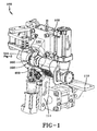
Figure 1 is a perspective view of a rubber applicator apparatus of the present invention; -
Figure 2 is a close-up perspective view of a roller and nozzle of the rubber applicator apparatus of the present invention; -
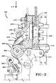
Figure 3 is a side cross-sectional view of the apparatus ofFigure 1 ; -
Figure 4 is a side view of the roller and nozzle wherein the nozzle is shown with half the nozzle removed; -
Figure 5 is a side view of the nozzle; -
Figure 6 is a perspective view of the nozzle outlet; -
Figure 7 is an end view of the outlet of the nozzle; and -
Figure 8 is a side view of the rubber applicator apparatus shown applying a rubber strip to a tire building drum. - A first embodiment of a
rubber applicator apparatus 100 is shown inFigures 1-7 . Theapplicator apparatus 100 provides a novel apparatus to form elastomeric tire components quickly and efficiently from a single continuously wound strip or multiple strips of unvulcanized rubber. A continuous strip of unvulcanized rubber may be applied directly onto a tire building surface such as a tire building drum A as shown inFigure 8 , or a toroidal shaped core (not shown). - As shown in
Figure 1 , theapplicator apparatus 100 includes a support frame 110 (parts of which have been removed for clarity), and aroller nozzle 200. The support frame may further include support rails for translating the entire applicator apparatus in the X, Y and Z direction (not shown). Arotatable linkage 111 is mounted to thesupport frame 110, and functions to pivot theroller 300 aboutfixed point 114 as shown inFigure 4 . Therotatable linkage 111 is connected toactuator arm 112 which translates fore and aft to pivot therotatable linkage 111 about thefixed point 114. - As shown in
Figure 3 , thesupport frame 110 includes a mountingflange 102 for connecting to a rubber pumping means such as an extruder, gear pump, extruder-gear pump combination, or rubber injector (not shown). An extruder suitable for use with the invention is made by AZ Formen und Maschinenbau of Munich, Germany. The rubber or elastomer output from the rubber pumping means is fed into aninternal passage 103 of the mounting flange and then into atransition member 120. Thetransition member 120 has aninterior channel 126 having aninlet end 122 and anoutlet end 124. Theinlet end 122 preferably has a larger area than theoutlet end 124, resulting in a decreasing area or a funnel-shapedchannel 126.Channel 126 is also angled downwardly in the range of about 30 to about 75 degrees with respect to the X axis, more typically 45- 60 degrees. Theoutlet end 124 of the transition member is connected to aninlet end 202 of anozzle 210. - The
nozzle 210, as best shown inFigures 3-7 , has a generally cylindrically shapedouter body 211 terminating in anangled face 212 at the nozzle outlet 223. The nozzle has aninterior channel 221 that has a decreasing area from theinlet end 202 to the outlet orifice 223 of the nozzle. Theangled face 212 of the nozzle terminates in anedge 214. Theedge 214 forms a juncture between theangled face 212 and acurved outlet surface 230 of the nozzle. The lower surface of theedge 214 has a shapeddie surface 216 that cooperates with the curved outer surface of theroller 300 to form the nozzle outlet. The shapeddie surface 216 in this example, has aflat edge 217 with opposed beveled ends 218, 219 which forms a strip with beveled edges. The die shape is not limited to the configuration shown, and may form other shapes as desired. The curvedlower surface 230 of the nozzle is shaped to cooperate with the outer surface ofroller 300 in order to form the strip. The lower surface of the nozzle has anopening 231 that is preferably V-shaped. Theopening 231 has an axial width A and a longitudinal length L, wherein the length is greater than 1.5 times the axial width A. Theopening 231 is wide to allow the rubber to engage the outer surface of theroller 300 before exiting theoutlet 232. The wide opening allows the rubber or elastomer to engage the outer surface of the roller. As theroller 300 rotates, the outer surface of theroller 300 engages the rubber flowing through the nozzle, and pulls the rubber towards thenozzle outlet 232. The pulling of the rubber by the roller lowers the internal pressure and temperature of the rubber as it travels through thesystem 100. The lower extrusion temperatures reduce stretch of the rubber. As the rubber is pulled towards thenozzle outlet 232, it is shaped bydie surfaces upper edge 214 and the rollerouter surface 300. Preferably, theroller 300 is heated. - The outlet die
surfaces nozzle 212 may be optionally heated to a temperature in the range of from 0 to 200 degrees F using external or internal heaters (not shown). - As shown in
Figure 8 , thenozzle 210 is oriented with respect to the tire building drum A, core (not shown) or other application surface typically at an angle β in the range of from 0 to 50 degrees, more typically in the range of from 20 to 35 degrees. The rubber from the nozzle is first adhered to theroller 300, and then pushed through the nozzle outlet and then applied by therotating roller 300 to the tire building drum A, as shown inFigure 8 . Astitcher roller 400 is positioned adjacent theroller 300, and applies pressure to secure the strip onto the drum. Thestitcher roller 400 is attached to linkarm 402 that is pivotally connected to thesupport frame 110. Thestitcher roller 400 is connected toactuator arm 404 connected toactuator 406. - The
roller assembly 300 preferably has internal heaters for heating the outer surface in the range of from 200 to 400 degrees F, and more preferably in the range of 350 to 400 degrees F. Thus, the roller functions as a hot knife, smoothing and smearing the freshly deposited rubber, melting and blending the adjacent strips of rubber together, into a homogeneous mass. The higher roller temperature does not impact the curing of rubber due to the short residence time. Thestitcher assembly 400 performs a stitcher function due to the pressure of the roller against the drum, smoothing out the air pockets. The outer surface of the roller also helps shape the formed component. - The
roller assembly 300 preferably is connected to a linkage system 500 connected to an air cylinder as shown inFig. 4 , so that theroller 300 may be raised and lowered. - The following steps describe the formation of a tire component such as a sidewall, chafer, liner, or other elastomeric article. Rubber or elastomer is fed to a pumping means, such as an injector, gear pump, extruder or combination thereof. The rubber extrudate is pumped into the rubber applicator apparatus by the pumping means. In the applicator apparatus, the elastomeric material is fed from the extruder or pumping means (not shown) into an internal passage of the transition member. The internal passage of the transition member decreases in area and utilizes gravity to push the rubber down the internal passage. The elastomer or rubber flow exits the interior passage and enters a nozzle. The nozzle has a curved lower surface having an opening that is positioned in mating engagement with the roller. The opening on the lower curved surface of the nozzle has a wide area that presses the rubber directly onto the roller surface. As the roller rotates, it pulls the rubber through the nozzle towards the nozzle outlet. The pulling action by the roller reduces the temperature and pressure of the rubber, as less extruder pressure is needed to pump the rubber through the system. As the rubber exits the nozzle, it is shaped as it passes through the nozzle outlet by the die surfaces 217, 218, 219 forming a shaped strip of rubber. The strip of rubber is then immediately applied to a mandrel or tire building surface. The nozzle assembly is capable of translating in three directions in discrete index positions in order to accurately apply the rubber to the building surface. The support surface can be is a toroid shaped core or a cylindrical shaped tire building drum, or any other desired shape. The primary advantage of applying the strip to a toroidially shaped surface is the finished part is accurately positioned in a green uncured state at the proper orientation to be molded without requiring any change in orientation from the condition in which the strip was initially formed.
- The extrudate exits the nozzle in a strip form, having the desired shape of the exit orifice of the nozzle. If a drum or toroid is used as an applicator surface, as the drum or core rotates, a continuous annular strip may be formed. The nozzle can be indexed axially so to form the desired shape of the component. The nozzle can be controlled by a control system wherein the movement of the nozzle so that the multiple layers of strip dictates the shape of the desired tire component.
Claims (15)
- An apparatus for applying a strip of elastomeric material to a surface, the apparatus comprising a nozzle (210) having an inlet (202) in fluid communication with a pumping means, the nozzle (210) having an upper surface and a lower surface, wherein the lower surface has a curved shape for mating engagement with an outer surface of a rotatable roller (300), the lower surface further having an opening (231) which is configured to be positioned onto the roller outer surface.
- The apparatus of claim 1, wherein the nozzle (210) is configured to compress the elastomeric material directly onto the outer surface of the roller (300).
- The apparatus of claim 1 or 2, wherein the elastomeric material is in a molten state in the nozzle (210) and/or in the apparatus (100).
- The apparatus of at least one of the previous claims, wherein the elastomeric material is in a molten state prior to entering the apparatus (100) and/or wherein the elastomeric material is in a molten state when it is applied to the roller outer surface.
- The apparatus of at least one of the previous claims, wherein the nozzle (210) has a shaped die surface (216) that cooperates with the curved outer surface of the roller (300) to form a nozzle outlet.
- The apparatus of at least one of the previous claims, wherein said roller configured to be heated to a temperature in the range of from 93°C to 177°C.
- The apparatus of at least one of the previous claims, wherein the pumping means is an extruder or an extruder in combination with a gear pump.
- The apparatus of at least one of the previous claims, wherein the apparatus comprises an interior channel (126) in connection with the nozzle (210), wherein the interior channel (126) decreases in area, preferably towards the nozzle (210).
- The apparatus of at least one of the previous claims, wherein the outlet of the nozzle (210) is V shaped.
- A method of forming a strip of elastomeric material, the method comprising the steps of: pumping an elastomeric material through a nozzle (210), positioning an opening of the nozzle (210) in mating engagement with a rotatable roller (300), rotating the roller (300) so that the rotation of the roller (300) pulls the elastomeric material through the outlet of the nozzle (210), and forming a strip.
- The method of claim 10, wherein the elastomeric material is in a molten state.
- The method of claim 10 or 11, wherein the outlet of the nozzle (210) is formed between the roller outer surface and an edge of the nozzle (210).
- The method of at least one of the claims 11 or 12, further comprising the steps of pumping the molten elastomeric material through a die positioned at the outlet of the nozzle (210) and then forming a shaped elastomer strip onto an outer surface of the rotating roller (300).
- The method of at least one of the claims 10 to 13, further comprising the steps of pressing the roller (300) against a tire building drum so that the strip of rubber adheres to the surface of the tire building drum.
- The method of at least one of the claims, wherein said nozzle (210) compresses said elastomeric material directly onto the outer surface of the roller (300).
Applications Claiming Priority (2)
| Application Number | Priority Date | Filing Date | Title |
|---|---|---|---|
| US201562186699P | 2015-06-30 | 2015-06-30 | |
| US201562186730P | 2015-06-30 | 2015-06-30 |
Publications (2)
| Publication Number | Publication Date |
|---|---|
| EP3112142A1 true EP3112142A1 (en) | 2017-01-04 |
| EP3112142B1 EP3112142B1 (en) | 2019-12-25 |
Family
ID=56134255
Family Applications (2)
| Application Number | Title | Priority Date | Filing Date |
|---|---|---|---|
| EP16175063.3A Active EP3112142B1 (en) | 2015-06-30 | 2016-06-17 | Apparatus and method for forming an elastomeric strip |
| EP16175049.2A Not-in-force EP3112141B1 (en) | 2015-06-30 | 2016-06-17 | Apparatus and method for forming an elastomeric strip |
Family Applications After (1)
| Application Number | Title | Priority Date | Filing Date |
|---|---|---|---|
| EP16175049.2A Not-in-force EP3112141B1 (en) | 2015-06-30 | 2016-06-17 | Apparatus and method for forming an elastomeric strip |
Country Status (1)
| Country | Link |
|---|---|
| EP (2) | EP3112142B1 (en) |
Families Citing this family (1)
| Publication number | Priority date | Publication date | Assignee | Title |
|---|---|---|---|---|
| US20190184656A1 (en) * | 2017-12-19 | 2019-06-20 | The Goodyear Tire & Rubber Company | Strip lamination method and apparatus |
Citations (6)
| Publication number | Priority date | Publication date | Assignee | Title |
|---|---|---|---|---|
| US4927482A (en) * | 1987-11-06 | 1990-05-22 | Hermann Berstorff Maschinenbau Gmbh | Method and apparatus for producing tread strips for automotive vehicle tires |
| US4963207A (en) | 1986-09-17 | 1990-10-16 | Compagnie Generale Des Etablissements Michelin | Method and apparatus of manufacturing a tire by the laying of rubber products onto a firm support |
| US6372070B1 (en) | 1998-06-29 | 2002-04-16 | Bridgestone Corporation | Process and apparatus for laying rubber materials for tire-constitutional members |
| US20090274786A1 (en) * | 2007-10-30 | 2009-11-05 | Michelin Recherche Et Technique S.A. | Device for Extruding a Strip of Rubber |
| US20110052827A1 (en) * | 2007-05-11 | 2011-03-03 | Societe De Technologie Michelin | Articulated Nozzle and Method of Applying a Strip of Viscoelastic Material Using Said Nozzle |
| US20130020737A1 (en) * | 2011-07-20 | 2013-01-24 | Extrusion Dies Industries, Llc | Sculpted extrusion die |
Family Cites Families (1)
| Publication number | Priority date | Publication date | Assignee | Title |
|---|---|---|---|---|
| US7175726B2 (en) * | 2004-02-25 | 2007-02-13 | Toyo Tire & Rubber Co., Ltd. | Continuous rubber-strip forming apparatus and process |
-
2016
- 2016-06-17 EP EP16175063.3A patent/EP3112142B1/en active Active
- 2016-06-17 EP EP16175049.2A patent/EP3112141B1/en not_active Not-in-force
Patent Citations (6)
| Publication number | Priority date | Publication date | Assignee | Title |
|---|---|---|---|---|
| US4963207A (en) | 1986-09-17 | 1990-10-16 | Compagnie Generale Des Etablissements Michelin | Method and apparatus of manufacturing a tire by the laying of rubber products onto a firm support |
| US4927482A (en) * | 1987-11-06 | 1990-05-22 | Hermann Berstorff Maschinenbau Gmbh | Method and apparatus for producing tread strips for automotive vehicle tires |
| US6372070B1 (en) | 1998-06-29 | 2002-04-16 | Bridgestone Corporation | Process and apparatus for laying rubber materials for tire-constitutional members |
| US20110052827A1 (en) * | 2007-05-11 | 2011-03-03 | Societe De Technologie Michelin | Articulated Nozzle and Method of Applying a Strip of Viscoelastic Material Using Said Nozzle |
| US20090274786A1 (en) * | 2007-10-30 | 2009-11-05 | Michelin Recherche Et Technique S.A. | Device for Extruding a Strip of Rubber |
| US20130020737A1 (en) * | 2011-07-20 | 2013-01-24 | Extrusion Dies Industries, Llc | Sculpted extrusion die |
Also Published As
| Publication number | Publication date |
|---|---|
| EP3112142B1 (en) | 2019-12-25 |
| EP3112141A1 (en) | 2017-01-04 |
| EP3112141B1 (en) | 2019-01-23 |
Similar Documents
| Publication | Publication Date | Title |
|---|---|---|
| EP3260285A1 (en) | An apparatus for forming an elastomeric strip with rotatable nozzle applicator | |
| EP1418043B1 (en) | A method and apparatus for forming an annular elastomeric tire component | |
| US6666940B2 (en) | Manufacture of a strip by extrusion of a tube then flattening the tube | |
| US9120262B2 (en) | Apparatus for extruding a polymeric material and extrusion head therefor | |
| US9403309B2 (en) | Method for controlling the heating of an extrusion device of a semi-finished product made of elastomeric material | |
| RU2636493C2 (en) | Method for regulating thickness of continuous elongated element made of elastomeric material while assembling tires | |
| EP0655322B1 (en) | Method of forming tire bead assembly | |
| US9738045B2 (en) | Apparatus for forming an elastomeric strip | |
| US20070031529A1 (en) | Apparatus for forming elastomeric tire component and a tire | |
| EP3112142B1 (en) | Apparatus and method for forming an elastomeric strip | |
| EP2055469A1 (en) | Extruding tread components directly into a tire mold | |
| JP4902549B2 (en) | Method and apparatus for manufacturing and arranging tire circumferential reinforcement and tire obtained by this method | |
| EP1749649A2 (en) | A method for forming an elastomeric component | |
| EP3501807B1 (en) | Method and apparatus for forming rubber reinforced component | |
| EP3670141B1 (en) | Methods of making composite innerliner and tire having such a composite innerliner | |
| US10843219B2 (en) | Installation for fabricating a thermal protection covering of a body or of a rear assembly for a thruster, and associated methods | |
| US20200070395A1 (en) | Method of forming an elastomeric strip | |
| US7780809B2 (en) | Method for forming elastomeric tire component and a tire | |
| CN106427000B (en) | Method of forming an elastic belt | |
| US4569711A (en) | Manufacture of elastomeric material coponents | |
| EP2191985A1 (en) | Pneumatic tire, tire molding apparatus and method of molding |
Legal Events
| Date | Code | Title | Description |
|---|---|---|---|
| PUAI | Public reference made under article 153(3) epc to a published international application that has entered the european phase |
Free format text: ORIGINAL CODE: 0009012 |
|
| STAA | Information on the status of an ep patent application or granted ep patent |
Free format text: STATUS: THE APPLICATION HAS BEEN PUBLISHED |
|
| AK | Designated contracting states |
Kind code of ref document: A1 Designated state(s): AL AT BE BG CH CY CZ DE DK EE ES FI FR GB GR HR HU IE IS IT LI LT LU LV MC MK MT NL NO PL PT RO RS SE SI SK SM TR |
|
| AX | Request for extension of the european patent |
Extension state: BA ME |
|
| STAA | Information on the status of an ep patent application or granted ep patent |
Free format text: STATUS: REQUEST FOR EXAMINATION WAS MADE |
|
| 17P | Request for examination filed |
Effective date: 20170704 |
|
| RBV | Designated contracting states (corrected) |
Designated state(s): AL AT BE BG CH CY CZ DE DK EE ES FI FR GB GR HR HU IE IS IT LI LT LU LV MC MK MT NL NO PL PT RO RS SE SI SK SM TR |
|
| STAA | Information on the status of an ep patent application or granted ep patent |
Free format text: STATUS: EXAMINATION IS IN PROGRESS |
|
| 17Q | First examination report despatched |
Effective date: 20170919 |
|
| REG | Reference to a national code |
Ref country code: DE Ref legal event code: R079 Ref document number: 602016026705 Country of ref document: DE Free format text: PREVIOUS MAIN CLASS: B29D0030300000 Ipc: B29K0019000000 |
|
| GRAP | Despatch of communication of intention to grant a patent |
Free format text: ORIGINAL CODE: EPIDOSNIGR1 |
|
| STAA | Information on the status of an ep patent application or granted ep patent |
Free format text: STATUS: GRANT OF PATENT IS INTENDED |
|
| RIC1 | Information provided on ipc code assigned before grant |
Ipc: B29C 48/03 20190101ALI20190709BHEP Ipc: B29D 30/30 20060101ALI20190709BHEP Ipc: B29D 30/62 20060101ALI20190709BHEP Ipc: B29C 48/35 20190101ALI20190709BHEP Ipc: B29K 19/00 20060101AFI20190709BHEP Ipc: B29C 48/30 20190101ALI20190709BHEP |
|
| INTG | Intention to grant announced |
Effective date: 20190726 |
|
| GRAS | Grant fee paid |
Free format text: ORIGINAL CODE: EPIDOSNIGR3 |
|
| GRAA | (expected) grant |
Free format text: ORIGINAL CODE: 0009210 |
|
| STAA | Information on the status of an ep patent application or granted ep patent |
Free format text: STATUS: THE PATENT HAS BEEN GRANTED |
|
| AK | Designated contracting states |
Kind code of ref document: B1 Designated state(s): AL AT BE BG CH CY CZ DE DK EE ES FI FR GB GR HR HU IE IS IT LI LT LU LV MC MK MT NL NO PL PT RO RS SE SI SK SM TR |
|
| REG | Reference to a national code |
Ref country code: GB Ref legal event code: FG4D |
|
| REG | Reference to a national code |
Ref country code: CH Ref legal event code: EP |
|
| REG | Reference to a national code |
Ref country code: AT Ref legal event code: REF Ref document number: 1216704 Country of ref document: AT Kind code of ref document: T Effective date: 20200115 |
|
| REG | Reference to a national code |
Ref country code: DE Ref legal event code: R096 Ref document number: 602016026705 Country of ref document: DE |
|
| REG | Reference to a national code |
Ref country code: IE Ref legal event code: FG4D |
|
| REG | Reference to a national code |
Ref country code: NL Ref legal event code: FP |
|
| PG25 | Lapsed in a contracting state [announced via postgrant information from national office to epo] |
Ref country code: FI Free format text: LAPSE BECAUSE OF FAILURE TO SUBMIT A TRANSLATION OF THE DESCRIPTION OR TO PAY THE FEE WITHIN THE PRESCRIBED TIME-LIMIT Effective date: 20191225 Ref country code: GR Free format text: LAPSE BECAUSE OF FAILURE TO SUBMIT A TRANSLATION OF THE DESCRIPTION OR TO PAY THE FEE WITHIN THE PRESCRIBED TIME-LIMIT Effective date: 20200326 Ref country code: NO Free format text: LAPSE BECAUSE OF FAILURE TO SUBMIT A TRANSLATION OF THE DESCRIPTION OR TO PAY THE FEE WITHIN THE PRESCRIBED TIME-LIMIT Effective date: 20200325 Ref country code: BG Free format text: LAPSE BECAUSE OF FAILURE TO SUBMIT A TRANSLATION OF THE DESCRIPTION OR TO PAY THE FEE WITHIN THE PRESCRIBED TIME-LIMIT Effective date: 20200325 Ref country code: LV Free format text: LAPSE BECAUSE OF FAILURE TO SUBMIT A TRANSLATION OF THE DESCRIPTION OR TO PAY THE FEE WITHIN THE PRESCRIBED TIME-LIMIT Effective date: 20191225 Ref country code: SE Free format text: LAPSE BECAUSE OF FAILURE TO SUBMIT A TRANSLATION OF THE DESCRIPTION OR TO PAY THE FEE WITHIN THE PRESCRIBED TIME-LIMIT Effective date: 20191225 Ref country code: LT Free format text: LAPSE BECAUSE OF FAILURE TO SUBMIT A TRANSLATION OF THE DESCRIPTION OR TO PAY THE FEE WITHIN THE PRESCRIBED TIME-LIMIT Effective date: 20191225 |
|
| REG | Reference to a national code |
Ref country code: LT Ref legal event code: MG4D |
|
| PG25 | Lapsed in a contracting state [announced via postgrant information from national office to epo] |
Ref country code: RS Free format text: LAPSE BECAUSE OF FAILURE TO SUBMIT A TRANSLATION OF THE DESCRIPTION OR TO PAY THE FEE WITHIN THE PRESCRIBED TIME-LIMIT Effective date: 20191225 Ref country code: HR Free format text: LAPSE BECAUSE OF FAILURE TO SUBMIT A TRANSLATION OF THE DESCRIPTION OR TO PAY THE FEE WITHIN THE PRESCRIBED TIME-LIMIT Effective date: 20191225 |
|
| PG25 | Lapsed in a contracting state [announced via postgrant information from national office to epo] |
Ref country code: AL Free format text: LAPSE BECAUSE OF FAILURE TO SUBMIT A TRANSLATION OF THE DESCRIPTION OR TO PAY THE FEE WITHIN THE PRESCRIBED TIME-LIMIT Effective date: 20191225 |
|
| PG25 | Lapsed in a contracting state [announced via postgrant information from national office to epo] |
Ref country code: EE Free format text: LAPSE BECAUSE OF FAILURE TO SUBMIT A TRANSLATION OF THE DESCRIPTION OR TO PAY THE FEE WITHIN THE PRESCRIBED TIME-LIMIT Effective date: 20191225 Ref country code: CZ Free format text: LAPSE BECAUSE OF FAILURE TO SUBMIT A TRANSLATION OF THE DESCRIPTION OR TO PAY THE FEE WITHIN THE PRESCRIBED TIME-LIMIT Effective date: 20191225 Ref country code: PT Free format text: LAPSE BECAUSE OF FAILURE TO SUBMIT A TRANSLATION OF THE DESCRIPTION OR TO PAY THE FEE WITHIN THE PRESCRIBED TIME-LIMIT Effective date: 20200520 Ref country code: RO Free format text: LAPSE BECAUSE OF FAILURE TO SUBMIT A TRANSLATION OF THE DESCRIPTION OR TO PAY THE FEE WITHIN THE PRESCRIBED TIME-LIMIT Effective date: 20191225 |
|
| PG25 | Lapsed in a contracting state [announced via postgrant information from national office to epo] |
Ref country code: SM Free format text: LAPSE BECAUSE OF FAILURE TO SUBMIT A TRANSLATION OF THE DESCRIPTION OR TO PAY THE FEE WITHIN THE PRESCRIBED TIME-LIMIT Effective date: 20191225 Ref country code: IS Free format text: LAPSE BECAUSE OF FAILURE TO SUBMIT A TRANSLATION OF THE DESCRIPTION OR TO PAY THE FEE WITHIN THE PRESCRIBED TIME-LIMIT Effective date: 20200425 Ref country code: SK Free format text: LAPSE BECAUSE OF FAILURE TO SUBMIT A TRANSLATION OF THE DESCRIPTION OR TO PAY THE FEE WITHIN THE PRESCRIBED TIME-LIMIT Effective date: 20191225 |
|
| REG | Reference to a national code |
Ref country code: DE Ref legal event code: R097 Ref document number: 602016026705 Country of ref document: DE |
|
| PG25 | Lapsed in a contracting state [announced via postgrant information from national office to epo] |
Ref country code: DK Free format text: LAPSE BECAUSE OF FAILURE TO SUBMIT A TRANSLATION OF THE DESCRIPTION OR TO PAY THE FEE WITHIN THE PRESCRIBED TIME-LIMIT Effective date: 20191225 Ref country code: ES Free format text: LAPSE BECAUSE OF FAILURE TO SUBMIT A TRANSLATION OF THE DESCRIPTION OR TO PAY THE FEE WITHIN THE PRESCRIBED TIME-LIMIT Effective date: 20191225 |
|
| PLBE | No opposition filed within time limit |
Free format text: ORIGINAL CODE: 0009261 |
|
| STAA | Information on the status of an ep patent application or granted ep patent |
Free format text: STATUS: NO OPPOSITION FILED WITHIN TIME LIMIT |
|
| REG | Reference to a national code |
Ref country code: AT Ref legal event code: MK05 Ref document number: 1216704 Country of ref document: AT Kind code of ref document: T Effective date: 20191225 |
|
| PG25 | Lapsed in a contracting state [announced via postgrant information from national office to epo] |
Ref country code: SI Free format text: LAPSE BECAUSE OF FAILURE TO SUBMIT A TRANSLATION OF THE DESCRIPTION OR TO PAY THE FEE WITHIN THE PRESCRIBED TIME-LIMIT Effective date: 20191225 |
|
| 26N | No opposition filed |
Effective date: 20200928 |
|
| PG25 | Lapsed in a contracting state [announced via postgrant information from national office to epo] |
Ref country code: AT Free format text: LAPSE BECAUSE OF FAILURE TO SUBMIT A TRANSLATION OF THE DESCRIPTION OR TO PAY THE FEE WITHIN THE PRESCRIBED TIME-LIMIT Effective date: 20191225 Ref country code: MC Free format text: LAPSE BECAUSE OF FAILURE TO SUBMIT A TRANSLATION OF THE DESCRIPTION OR TO PAY THE FEE WITHIN THE PRESCRIBED TIME-LIMIT Effective date: 20191225 |
|
| REG | Reference to a national code |
Ref country code: CH Ref legal event code: PL |
|
| PG25 | Lapsed in a contracting state [announced via postgrant information from national office to epo] |
Ref country code: PL Free format text: LAPSE BECAUSE OF FAILURE TO SUBMIT A TRANSLATION OF THE DESCRIPTION OR TO PAY THE FEE WITHIN THE PRESCRIBED TIME-LIMIT Effective date: 20191225 |
|
| GBPC | Gb: european patent ceased through non-payment of renewal fee |
Effective date: 20200617 |
|
| PG25 | Lapsed in a contracting state [announced via postgrant information from national office to epo] |
Ref country code: LU Free format text: LAPSE BECAUSE OF NON-PAYMENT OF DUE FEES Effective date: 20200617 |
|
| REG | Reference to a national code |
Ref country code: BE Ref legal event code: MM Effective date: 20200630 |
|
| PG25 | Lapsed in a contracting state [announced via postgrant information from national office to epo] |
Ref country code: CH Free format text: LAPSE BECAUSE OF NON-PAYMENT OF DUE FEES Effective date: 20200630 Ref country code: LI Free format text: LAPSE BECAUSE OF NON-PAYMENT OF DUE FEES Effective date: 20200630 Ref country code: IE Free format text: LAPSE BECAUSE OF NON-PAYMENT OF DUE FEES Effective date: 20200617 Ref country code: GB Free format text: LAPSE BECAUSE OF NON-PAYMENT OF DUE FEES Effective date: 20200617 |
|
| PG25 | Lapsed in a contracting state [announced via postgrant information from national office to epo] |
Ref country code: BE Free format text: LAPSE BECAUSE OF NON-PAYMENT OF DUE FEES Effective date: 20200630 |
|
| PGFP | Annual fee paid to national office [announced via postgrant information from national office to epo] |
Ref country code: NL Payment date: 20210615 Year of fee payment: 6 |
|
| PG25 | Lapsed in a contracting state [announced via postgrant information from national office to epo] |
Ref country code: TR Free format text: LAPSE BECAUSE OF FAILURE TO SUBMIT A TRANSLATION OF THE DESCRIPTION OR TO PAY THE FEE WITHIN THE PRESCRIBED TIME-LIMIT Effective date: 20191225 Ref country code: MT Free format text: LAPSE BECAUSE OF FAILURE TO SUBMIT A TRANSLATION OF THE DESCRIPTION OR TO PAY THE FEE WITHIN THE PRESCRIBED TIME-LIMIT Effective date: 20191225 Ref country code: CY Free format text: LAPSE BECAUSE OF FAILURE TO SUBMIT A TRANSLATION OF THE DESCRIPTION OR TO PAY THE FEE WITHIN THE PRESCRIBED TIME-LIMIT Effective date: 20191225 |
|
| PG25 | Lapsed in a contracting state [announced via postgrant information from national office to epo] |
Ref country code: MK Free format text: LAPSE BECAUSE OF FAILURE TO SUBMIT A TRANSLATION OF THE DESCRIPTION OR TO PAY THE FEE WITHIN THE PRESCRIBED TIME-LIMIT Effective date: 20191225 |
|
| PGFP | Annual fee paid to national office [announced via postgrant information from national office to epo] |
Ref country code: IT Payment date: 20220510 Year of fee payment: 7 Ref country code: FR Payment date: 20220408 Year of fee payment: 7 Ref country code: DE Payment date: 20220427 Year of fee payment: 7 |
|
| REG | Reference to a national code |
Ref country code: NL Ref legal event code: MM Effective date: 20220701 |
|
| PG25 | Lapsed in a contracting state [announced via postgrant information from national office to epo] |
Ref country code: NL Free format text: LAPSE BECAUSE OF NON-PAYMENT OF DUE FEES Effective date: 20220701 |
|
| REG | Reference to a national code |
Ref country code: DE Ref legal event code: R119 Ref document number: 602016026705 Country of ref document: DE |
|
| PG25 | Lapsed in a contracting state [announced via postgrant information from national office to epo] |
Ref country code: DE Free format text: LAPSE BECAUSE OF NON-PAYMENT OF DUE FEES Effective date: 20240103 |
|
| PG25 | Lapsed in a contracting state [announced via postgrant information from national office to epo] |
Ref country code: FR Free format text: LAPSE BECAUSE OF NON-PAYMENT OF DUE FEES Effective date: 20230630 |
|
| PG25 | Lapsed in a contracting state [announced via postgrant information from national office to epo] |
Ref country code: IT Free format text: LAPSE BECAUSE OF NON-PAYMENT OF DUE FEES Effective date: 20230617 |