EP3112118A1 - Method and apparatus for producing a component by use of a vacuum film - Google Patents
Method and apparatus for producing a component by use of a vacuum film Download PDFInfo
- Publication number
- EP3112118A1 EP3112118A1 EP16167386.8A EP16167386A EP3112118A1 EP 3112118 A1 EP3112118 A1 EP 3112118A1 EP 16167386 A EP16167386 A EP 16167386A EP 3112118 A1 EP3112118 A1 EP 3112118A1
- Authority
- EP
- European Patent Office
- Prior art keywords
- fold
- clip
- support
- film
- support surface
- Prior art date
- Legal status (The legal status is an assumption and is not a legal conclusion. Google has not performed a legal analysis and makes no representation as to the accuracy of the status listed.)
- Withdrawn
Links
- 238000000034 method Methods 0.000 title claims description 18
- 239000011265 semifinished product Substances 0.000 claims abstract description 53
- 238000007789 sealing Methods 0.000 claims abstract description 46
- 239000011208 reinforced composite material Substances 0.000 claims abstract description 15
- 230000003014 reinforcing effect Effects 0.000 claims abstract description 12
- 238000004519 manufacturing process Methods 0.000 claims abstract description 10
- 238000003825 pressing Methods 0.000 claims description 9
- 239000000463 material Substances 0.000 description 21
- 239000004033 plastic Substances 0.000 description 18
- 229920003023 plastic Polymers 0.000 description 18
- 238000013461 design Methods 0.000 description 9
- 230000035882 stress Effects 0.000 description 8
- 239000000835 fiber Substances 0.000 description 6
- 239000003822 epoxy resin Substances 0.000 description 4
- 238000002347 injection Methods 0.000 description 4
- 239000007924 injection Substances 0.000 description 4
- 229920000647 polyepoxide Polymers 0.000 description 4
- 238000000926 separation method Methods 0.000 description 4
- 230000015572 biosynthetic process Effects 0.000 description 3
- 230000008878 coupling Effects 0.000 description 3
- 238000010168 coupling process Methods 0.000 description 3
- 238000005859 coupling reaction Methods 0.000 description 3
- 239000000696 magnetic material Substances 0.000 description 3
- OKTJSMMVPCPJKN-UHFFFAOYSA-N Carbon Chemical compound [C] OKTJSMMVPCPJKN-UHFFFAOYSA-N 0.000 description 2
- 229920002430 Fibre-reinforced plastic Polymers 0.000 description 2
- 239000012790 adhesive layer Substances 0.000 description 2
- 229910052799 carbon Inorganic materials 0.000 description 2
- 239000011248 coating agent Substances 0.000 description 2
- 238000000576 coating method Methods 0.000 description 2
- 239000003086 colorant Substances 0.000 description 2
- 239000011151 fibre-reinforced plastic Substances 0.000 description 2
- 238000010438 heat treatment Methods 0.000 description 2
- 239000002184 metal Substances 0.000 description 2
- 239000004753 textile Substances 0.000 description 2
- 230000008646 thermal stress Effects 0.000 description 2
- 239000000853 adhesive Substances 0.000 description 1
- 239000002131 composite material Substances 0.000 description 1
- 238000010276 construction Methods 0.000 description 1
- 230000005294 ferromagnetic effect Effects 0.000 description 1
- 239000003302 ferromagnetic material Substances 0.000 description 1
- 239000003365 glass fiber Substances 0.000 description 1
- 238000001802 infusion Methods 0.000 description 1
- 239000011159 matrix material Substances 0.000 description 1
- 238000005259 measurement Methods 0.000 description 1
- 238000000465 moulding Methods 0.000 description 1
- 229920005989 resin Polymers 0.000 description 1
- 239000011347 resin Substances 0.000 description 1
- 238000009745 resin transfer moulding Methods 0.000 description 1
- 229920001169 thermoplastic Polymers 0.000 description 1
- 238000009827 uniform distribution Methods 0.000 description 1
- 238000009755 vacuum infusion Methods 0.000 description 1
- 239000002759 woven fabric Substances 0.000 description 1
Images


Classifications
-
- B—PERFORMING OPERATIONS; TRANSPORTING
- B32—LAYERED PRODUCTS
- B32B—LAYERED PRODUCTS, i.e. PRODUCTS BUILT-UP OF STRATA OF FLAT OR NON-FLAT, e.g. CELLULAR OR HONEYCOMB, FORM
- B32B37/00—Methods or apparatus for laminating, e.g. by curing or by ultrasonic bonding
- B32B37/10—Methods or apparatus for laminating, e.g. by curing or by ultrasonic bonding characterised by the pressing technique, e.g. using action of vacuum or fluid pressure
- B32B37/1018—Methods or apparatus for laminating, e.g. by curing or by ultrasonic bonding characterised by the pressing technique, e.g. using action of vacuum or fluid pressure using only vacuum
-
- B—PERFORMING OPERATIONS; TRANSPORTING
- B29—WORKING OF PLASTICS; WORKING OF SUBSTANCES IN A PLASTIC STATE IN GENERAL
- B29C—SHAPING OR JOINING OF PLASTICS; SHAPING OF MATERIAL IN A PLASTIC STATE, NOT OTHERWISE PROVIDED FOR; AFTER-TREATMENT OF THE SHAPED PRODUCTS, e.g. REPAIRING
- B29C70/00—Shaping composites, i.e. plastics material comprising reinforcements, fillers or preformed parts, e.g. inserts
- B29C70/04—Shaping composites, i.e. plastics material comprising reinforcements, fillers or preformed parts, e.g. inserts comprising reinforcements only, e.g. self-reinforcing plastics
- B29C70/28—Shaping operations therefor
- B29C70/40—Shaping or impregnating by compression not applied
- B29C70/42—Shaping or impregnating by compression not applied for producing articles of definite length, i.e. discrete articles
- B29C70/44—Shaping or impregnating by compression not applied for producing articles of definite length, i.e. discrete articles using isostatic pressure, e.g. pressure difference-moulding, vacuum bag-moulding, autoclave-moulding or expanding rubber-moulding
-
- B—PERFORMING OPERATIONS; TRANSPORTING
- B29—WORKING OF PLASTICS; WORKING OF SUBSTANCES IN A PLASTIC STATE IN GENERAL
- B29D—PRODUCING PARTICULAR ARTICLES FROM PLASTICS OR FROM SUBSTANCES IN A PLASTIC STATE
- B29D99/00—Subject matter not provided for in other groups of this subclass
- B29D99/001—Producing wall or panel-like structures, e.g. for hulls, fuselages, or buildings
- B29D99/0014—Producing wall or panel-like structures, e.g. for hulls, fuselages, or buildings provided with ridges or ribs, e.g. joined ribs
-
- B—PERFORMING OPERATIONS; TRANSPORTING
- B32—LAYERED PRODUCTS
- B32B—LAYERED PRODUCTS, i.e. PRODUCTS BUILT-UP OF STRATA OF FLAT OR NON-FLAT, e.g. CELLULAR OR HONEYCOMB, FORM
- B32B3/00—Layered products comprising a layer with external or internal discontinuities or unevennesses, or a layer of non-planar shape; Layered products comprising a layer having particular features of form
- B32B3/02—Layered products comprising a layer with external or internal discontinuities or unevennesses, or a layer of non-planar shape; Layered products comprising a layer having particular features of form characterised by features of form at particular places, e.g. in edge regions
- B32B3/08—Layered products comprising a layer with external or internal discontinuities or unevennesses, or a layer of non-planar shape; Layered products comprising a layer having particular features of form characterised by features of form at particular places, e.g. in edge regions characterised by added members at particular parts
-
- B—PERFORMING OPERATIONS; TRANSPORTING
- B32—LAYERED PRODUCTS
- B32B—LAYERED PRODUCTS, i.e. PRODUCTS BUILT-UP OF STRATA OF FLAT OR NON-FLAT, e.g. CELLULAR OR HONEYCOMB, FORM
- B32B3/00—Layered products comprising a layer with external or internal discontinuities or unevennesses, or a layer of non-planar shape; Layered products comprising a layer having particular features of form
- B32B3/26—Layered products comprising a layer with external or internal discontinuities or unevennesses, or a layer of non-planar shape; Layered products comprising a layer having particular features of form characterised by a particular shape of the outline of the cross-section of a continuous layer; characterised by a layer with cavities or internal voids ; characterised by an apertured layer
- B32B3/28—Layered products comprising a layer with external or internal discontinuities or unevennesses, or a layer of non-planar shape; Layered products comprising a layer having particular features of form characterised by a particular shape of the outline of the cross-section of a continuous layer; characterised by a layer with cavities or internal voids ; characterised by an apertured layer characterised by a layer comprising a deformed thin sheet, i.e. the layer having its entire thickness deformed out of the plane, e.g. corrugated, crumpled
-
- B—PERFORMING OPERATIONS; TRANSPORTING
- B29—WORKING OF PLASTICS; WORKING OF SUBSTANCES IN A PLASTIC STATE IN GENERAL
- B29C—SHAPING OR JOINING OF PLASTICS; SHAPING OF MATERIAL IN A PLASTIC STATE, NOT OTHERWISE PROVIDED FOR; AFTER-TREATMENT OF THE SHAPED PRODUCTS, e.g. REPAIRING
- B29C43/00—Compression moulding, i.e. applying external pressure to flow the moulding material; Apparatus therefor
- B29C43/32—Component parts, details or accessories; Auxiliary operations
- B29C43/36—Moulds for making articles of definite length, i.e. discrete articles
- B29C43/3642—Bags, bleeder sheets or cauls for isostatic pressing
- B29C2043/3644—Vacuum bags; Details thereof, e.g. fixing or clamping
-
- B—PERFORMING OPERATIONS; TRANSPORTING
- B29—WORKING OF PLASTICS; WORKING OF SUBSTANCES IN A PLASTIC STATE IN GENERAL
- B29C—SHAPING OR JOINING OF PLASTICS; SHAPING OF MATERIAL IN A PLASTIC STATE, NOT OTHERWISE PROVIDED FOR; AFTER-TREATMENT OF THE SHAPED PRODUCTS, e.g. REPAIRING
- B29C43/00—Compression moulding, i.e. applying external pressure to flow the moulding material; Apparatus therefor
- B29C43/02—Compression moulding, i.e. applying external pressure to flow the moulding material; Apparatus therefor of articles of definite length, i.e. discrete articles
- B29C43/10—Isostatic pressing, i.e. using non-rigid pressure-exerting members against rigid parts or dies
- B29C43/12—Isostatic pressing, i.e. using non-rigid pressure-exerting members against rigid parts or dies using bags surrounding the moulding material or using membranes contacting the moulding material
-
- B—PERFORMING OPERATIONS; TRANSPORTING
- B32—LAYERED PRODUCTS
- B32B—LAYERED PRODUCTS, i.e. PRODUCTS BUILT-UP OF STRATA OF FLAT OR NON-FLAT, e.g. CELLULAR OR HONEYCOMB, FORM
- B32B2262/00—Composition or structural features of fibres which form a fibrous or filamentary layer or are present as additives
- B32B2262/10—Inorganic fibres
- B32B2262/106—Carbon fibres, e.g. graphite fibres
-
- B—PERFORMING OPERATIONS; TRANSPORTING
- B32—LAYERED PRODUCTS
- B32B—LAYERED PRODUCTS, i.e. PRODUCTS BUILT-UP OF STRATA OF FLAT OR NON-FLAT, e.g. CELLULAR OR HONEYCOMB, FORM
- B32B2605/00—Vehicles
- B32B2605/18—Aircraft
-
- B—PERFORMING OPERATIONS; TRANSPORTING
- B64—AIRCRAFT; AVIATION; COSMONAUTICS
- B64C—AEROPLANES; HELICOPTERS
- B64C1/00—Fuselages; Constructional features common to fuselages, wings, stabilising surfaces or the like
- B64C1/06—Frames; Stringers; Longerons ; Fuselage sections
- B64C1/064—Stringers; Longerons
-
- B—PERFORMING OPERATIONS; TRANSPORTING
- B64—AIRCRAFT; AVIATION; COSMONAUTICS
- B64C—AEROPLANES; HELICOPTERS
- B64C1/00—Fuselages; Constructional features common to fuselages, wings, stabilising surfaces or the like
- B64C1/06—Frames; Stringers; Longerons ; Fuselage sections
- B64C1/12—Construction or attachment of skin panels
-
- B—PERFORMING OPERATIONS; TRANSPORTING
- B64—AIRCRAFT; AVIATION; COSMONAUTICS
- B64C—AEROPLANES; HELICOPTERS
- B64C1/00—Fuselages; Constructional features common to fuselages, wings, stabilising surfaces or the like
- B64C2001/0054—Fuselage structures substantially made from particular materials
- B64C2001/0072—Fuselage structures substantially made from particular materials from composite materials
Definitions
- the invention relates to a method and an apparatus for producing a component, in particular an aircraft structural component, from a fibre-reinforced composite material, in which use is made of a structure that comprises a mould for receiving a semifinished product, a semifinished product, and a vacuum film for sealing off the semifinished product from the ambient atmosphere.
- DE 10 2007 062 111 A1 describes a crossmember structure, composed of carbon-fibre reinforced plastic, which serves to support the individual panels of an aircraft floor system for separating a passenger cabin from a cargo compartment disposed beneath the passenger cabin. It is additionally known, for example from DE 10 2004 001 078 A1 or CN 100418850 , to provide aircraft fuselage segments with a skin and reinforcing elements (e.g. bulkheads, stringers) of fibre-reinforced composite materials.
- Aircraft structural components of fibre-reinforced composite materials may be produced according to a vacuum infusion method or a vacuum-assisted resin transfer moulding (RTM) method, in which a moulding of individual fibres, fibre prewovens or fibre prepregs of an existing semifinished product is disposed in or on a mould, and the semifinished product is then sealed off from the ambient atmosphere by means of a vacuum film.
- a hardenable plastic material such as, for example, an epoxy resin material, is then injected into the semifinished product through infusion hoses, which are connected to couplings that extend through the vacuum film in a sealed manner.
- the hardenable plastic material injected into the semifinished product is finally hardened under elevated pressure and/or elevated temperature, so as to obtain a composite material that contains reinforcing fibres embedded in a matrix composed of the hardened plastic material.
- the structure comprising the mould, the semifinished product and the vacuum film may be put into an autoclave.
- the invention is directed towards the object of specifying a method and an apparatus that make it possible to produce, in a reproducible manner and with uniformly high quality, a component, in particular an aircraft structural component, from a fibre-reinforced composite material by use of a structure that comprises a mould for receiving a semifinished product, a semifinished product, and a vacuum film for sealing off the semifinished product from the ambient atmosphere.
- a semifinished product containing reinforcing fibres, is disposed on a support surface of a support.
- the reinforcing fibres contained in the semifinished product may exist in the form of individual fibres or in the form of a fibre laying or fibre textile and be realized, for example, in the form of carbon fibres.
- the semifinished product may contain a plastic material.
- the plastic material may be, for example, a thermoplastic plastic material or a hardenable plastic material.
- the semifinished product may contain a hardenable resin material, in particular an epoxy resin.
- the semifinished product is realized in the form of a fibre prepreg, which comprises a textile or laying of reinforcing fibres provided with a surface coating of a hardenable plastic material.
- a design of the support surface of the support is preferably matched to a design of the semifinished product carried on the support surface.
- the support surface may be curved if the semifinished product is also of a curved design, this being the case, for example, if the semifinished product has a curved portion intended for production of a portion of an aircraft fuselage shell.
- the support surface may constitute a part of a surface of a recessed mould, in which the semifinished product can be disposed or accommodated.
- the semifinished product disposed on the support surface of the support is covered with a film.
- the film is preferably a vacuum film, which is suitable for sealing off a space, enclosed by the film, from the ambient atmosphere.
- the film is draped in such a manner that at least one fold, extending from the support surface of the support, is produced. If desired, a plurality of folds may be draped into the film.
- the at least one fold serves to avoid unwanted stresses in the film in the region of changes in the geometry of the semifinished product.
- allowance is also made for an amount of oversize of the film, by the formation of at least one fold, preferably in the region of an edge of the semifinished product.
- a sealing tape is applied along an open edge of the fold, in order to seal off from the ambient atmosphere a space defined by the support surface and the film, in the region of the fold. This results in regions in which the sealing tape lies on the film, and in regions in which portions of the sealing tape lie on one another. Two mutually opposite fold walls of the fold are thus formed partly by the film and partly by the sealing tape.
- the sealing tape is preferably provided with an adhesive layer in the region of at least one surface, i.e. realized as a single-sided or double-sided self-adhesive sealing tape.
- the sealing tape may be pressed on, for example, manually or by means of a so-called roller applicator.
- a clip is then applied over the fold in such a manner that the clip applies a clamping force, which presses the mutually opposite fold walls of the fold against each other.
- the clamping force applied by the clip thus counteracts separation of the sealing tape from the film and, in particular, separation of two sealing tape portions that are adhesively bonded to each other.
- a vacuum is generated in the space defined by the support surface of the support and the film.
- a pressure that is less than the pressure of the ambient atmosphere surrounding the structure comprising the support, the semifinished product and the film is generated in the space defined by the support surface of the support and the film.
- the space defined by the support surface of the support and the film may be connected to a suitable vacuum source, for example a pump.
- the pump may be connected, for example, to a coupling that extends through the film in a sealed manner.
- a plastic material preferably a hardenable plastic material
- the vacuum then ensures a rapid and uniform distribution of the plastic material in the semifinished product.
- the support, with the semifinished product and the film may be put into an oven or autoclave to harden plastic material contained in the semifinished product, and treated therein under elevated temperature and/or elevated pressure.
- the at least one fold deforms, since the film portion forming the fold is sucked in the direction of the support surface of the support.
- the clip used in the method for producing a component from a fibre-reinforced composite material as a result of the clamping force that it applies to press the mutually opposite fold walls of the fold against each other, counteracts stretching of the sealing tape in the edge region of the fold as the fold deforms.
- the risk of absence of seal tightness, or leakages, in the region of the sealing tape is thus significantly reduced by the use of the clip.
- the clip thus makes it possible, in a comparatively inelaborate manner, to make the component production process significantly more robust.
- the clip may be applied over the fold in such a manner that the clamping force applied by the clip presses the mutually opposite fold walls against each other in a region adjacent to the support surface of the support.
- the clip then counteracts stretching of the sealing tape precisely in the region of the fold walls in which stress peaks occur as the fold deforms, and which are therefore particularly susceptible to the occurrence of leakages.
- the clip may comprise two mutually opposite limbs.
- the limbs of the clip may be connected to each other at their first ends and, at least in the region of their second ends opposite to the first ends, may each provided with a clamping portion for applying the clamping force to the mutually opposite fold walls of the fold.
- the clamping portions provided on the limbs of the clip may extend over merely a portion of the limbs, in the region of the second ends of the limbs.
- the clip may also have clamping portions that extend over the entire length of the limbs or over a significant part of the length of the limbs.
- the clip is then suitable for pressing the mutually opposite fold walls against each other also in a region spaced from the support surface of the support.
- the clip may be elastically biased into a clamping position in which it presses the mutually opposite fold walls of the fold against each other.
- the clamp may comprise a locking device for locking the clip in a clamping position in which it presses the mutually opposite fold walls of the fold against each other.
- the clip can then be held in its clamping position in a particularly stable manner.
- the clip may be realized in the form of a screw clamp, a latch, or the like.
- the clip may be realized as an injection moulded part or as a metal part.
- the clip is fastened to the support surface of the support by means of a fastening means.
- the clip is thereby prevented from tilting in an unwanted manner relative to the support surface of the support.
- the fastening means may be adapted to apply a pressing force, directed in the direction of the support surface of the support, onto the film and/or onto the sealing tape. Separation of the sealing tape and/or of the film from the support surface of the support is thereby counteracted.
- the fastening means may comprise, for example, a magnet arrangement, which acts in combination with a support composed of a magnetic material, for example a ferromagnetic material, in order to hold the clip in a desired position relative to the support surface of the support.
- the fastening means may comprise a holding device, which encompasses an edge of the support in order to fix the clip in its position relative to the support surface of the support. Such a holding device may than also be used to fix the clip in its position relative to the support surface of the support if the support is not composed of a magnetic material.
- a dimension of the fold in a direction perpendicular to the support surface of the support may be set by means of a dimension defining means of the clamp.
- the dimension defining means may comprise, for example, a link extending between two mutually opposite limbs of the clip.
- the fold may be draped in such a manner that the fold extends, starting from the support surface to the support, to the link provided between the limbs of the clip.
- the clip can thus be used to define a required shape of the fold. This makes it possible to design even a manual draping operation in a relatively reproducible manner.
- differing dimensions of a plurality of folds in the direction perpendicular to the support surface of the support are set by means of the dimension defining means of a plurality of differently shaped clips.
- the clips may differ, for example, in respect of the length of their limbs and/or the positioning of the dimension defining means comprising, for example, a link extending between the limbs, relative to the limbs.
- the clips may be realized in a multiplicity of colours, or may be appropriately marked, in order to render suitable clips immediately identifiable for the production of differently shaped folds. This further increases the reproducibility of the process, and further simplifies the process as a whole.
- the film may be provided with at least one position marking for marking a position and/or a dimension of the at least one fold to be draped.
- the position marking makes it possible to define the position and the shape of the fold in a comparatively precise and reproducible manner, even in the case of a manual draping operation.
- the film may be provided with a plurality of position markings for marking the positions and/or dimensions of a plurality of folds to be draped.
- An apparatus for producing a component from a fibre-reinforced composite material comprises a support, having a support surface for disposing a semifinished product containing reinforcing fibres.
- the apparatus additionally comprises a film for covering the semifinished product, the film being adapted to be draped, in at least one portion, in such a manner that at least one fold, extending from the support surface of the support, is produced.
- a sealing tape of the apparatus is adapted to be applied along an open edge of the fold, in order to seal off from the ambient atmosphere a space defined by the support surface and the film, in the region of the fold, such that two mutually opposite fold walls of the fold are formed partly by the film and partly by the sealing tape.
- the apparatus additionally comprises a clip, which is adapted to be applied over the fold in such a manner that the clip applies a clamping force, which presses the mutually opposite fold walls of the fold against each other.
- the device comprises a vacuum generating means for generating a vacuum in the space defined by the support surface of the support and the film.
- the clip is adapted to be applied over the fold in such a manner that the clamping force applied by the clip presses the mutually opposite fold walls against each other in a region adjacent to the support surface of the support.
- the clip may comprise two mutually opposite limbs, which are connected to each other at their first ends and which, at least in the region of their second ends opposite to the first ends, are each provided with a clamping portion for applying the clamping force to the mutually opposite fold walls of the fold.
- the clip may be elastically biased into a clamping position in which it presses the mutually opposite fold walls of the fold against each other. Additionally or alternatively, the clip may comprise a locking device for locking the clip in a clamping position in which it presses the mutually opposite fold walls of the fold against each other.
- the clip may be fastened to the support surface of the support by means of a fastening means.
- the fastening means may be adapted to apply a pressing force, directed perpendicularly in relation to the support surface, onto the film and/or onto the sealing tape.
- the fastening means may comprise a magnet arrangement and/or a holding device, which encompass/encompasses an edge of the support.
- the clip may be equipped with a dimension defining means, which is adapted to set a dimension of the fold in a direction perpendicular to the support surface of the support.
- the dimension defining means may comprise a link extending between two mutually opposite limbs of the clip.
- the apparatus comprises a plurality of differently shaped clips, which are adapted to set, by means of their respective dimension defining means, differing dimensions of a plurality of folds in the direction perpendicular to the support surface of the support.
- the film may be provided with at least one position marking for marking a position and/or a dimension of the at least one fold to be draped.
- a semifinished product 16 containing reinforcing fibres can be disposed on the support surface 14 of the support 12.
- the exemplary semifinished product 16 shown in Figure 1 is a fibre prepreg, which comprises a woven fabric or laying of reinforcing fibres, in particular carbon fibres, which have been provided with a surface coating of a hardenable plastic material, in particular an epoxy resin.
- the semifinished product 16 is intended to be processed further to form an aircraft structural component that comprises an aircraft outer-skin portion and primary structural elements such as, for example, stringers, that are connected to the aircraft outer-skin portion.
- the semifinished product 16 is covered with a film 18.
- the film 18 is realized in the form of a vacuum film that is suitable for sealing off a space 19, which is delimited by the support surface 14 and the film 18 and in which the semifinished product 16 is accommodated, from the ambient atmosphere.
- the film 18 is adhesive-bonded to the support surface 14 by means of a sealing tape 20 provided with an adhesive layer on both sides.
- portions of the film 18 are draped in such a manner that a plurality of folds 22 are formed. These folds 22 prevent the formation of unwanted stresses in the film 18. In addition, allowance is also made for an amount of oversize of the film 18, by the formation of folds 24 disposed in the region of an edge of the semifinished product 16.
- the folds 22, 24 each extend upwardly from the support surface 14 of the support 12. In order to facilitate the draping of the folds 22, 24 into the film 18, the film is provided with position markings 25 for marking the positions of the folds 22, 24 to be draped.
- the sealing tape 20 is applied along an open edge of each fold 22, 24, as shown in Figure 2 .
- Mutually opposite fold walls 26, 28 of the folds 22, 24 are thus formed partly by the film 18 and partly by the sealing tape 20.
- the apparatus 10 additionally comprises a vacuum generating means 30, which may be realized, for example, in the form of a pump.
- the vacuum generating means 30 serves to generate a vacuum, i.e. a pressure that is reduced in respect of the ambient pressure, in the space 19 defined by the support surface 14 of the support 12 and the film 18.
- the apparatus 10 is equipped with an injection device 32, which serves to inject a hardenable plastic material, for example an epoxy resin, into the semifinished product 16.
- the injection device 32 comprises a plastic material reservoir 34, which is connected, via corresponding connecting hoses 36, 38, to corresponding couplings 40, 42, that extend through the film 18 in a sealed manner.
- plastic material injected by means of the injection device 32 is distributed rapidly and uniformly in the semifinished product 16.
- the structure comprising the support 12, the semifinished product 16 and the film 18 can be subjected to an elevated pressure and/or elevated temperature in an oven or autoclave (not shown in the figures).
- the folds 22, 24 deform, since the film portions forming the folds 22, 24 are sucked in the direction of the support surface 14.
- the folds 22, 24 may be made to move by an air-flow in an oven or autoclave used to harden the plastic material contained in the semifinished product 16 and/or injected into the semifinished product 16.
- thermal stresses may occur during a heat treatment of the structure comprising the support 12, the film 18 and the semifinished product 16. Consequently, stress peaks occur, particularly in regions of the sealing tape 20, used for sealing the folds 22, 24, that are adjacent to the support surface 14, which stress peaks may result in absence of seal tightness. This so-called "critical region" is identified in Figure 2 by the reference K.
- the apparatus 10 therefore additionally comprises a plurality of clips 44, which are applied over each fold 24 in such a manner that the mutually opposite fold walls 26, 28 of the folds 24, which are formed partly by the film 18 and partly by the sealing tape 20, are pressed against each other by a clamping force F K applied by the clips 44, see Figure 3 .
- the clamping force F K applied by each clip 44 counteracts stretching of the sealing tape 20 in the edge region of the fold 24. The risk of absence of seal tightness, or leakages, in the region of the sealing tape 20 is thereby significantly reduced.
- the clip 44 illustrated in Figure 3 comprises two mutually opposite limbs 46, 48, which are connected to each other in the region of their first ends. In the region of their second ends, which are opposite to their first ends, the limbs 46, 48 of the clip 44 are each provided with a clamping portion 50, 52. By pressing the clamping portions 50, 52 against each other, the clip 44 applies the clamping force F K to a region of the mutually opposite fold walls 26, 28 that is adjacent to the support surface 14 of the support 12, i.e. to the critical region K subjected to the stress peaks.
- the clip 44 shown in Figure 3 comprises a locking device 54 (indicated in schematic form only in Figure 3 ), which enables the clip 44 to be held securely in a clamping position in which it presses the mutually opposite fold walls 26, 28 of the fold 24 against each other. Furthermore, the clip 44 is provided with a fastening means 55, indicated only by a broken line in Figure 3 , for fastening the clip 44 to the support surface 14 of the support 12.
- the fastening means 55 comprises a holding device 57, which encompasses an edge of the support 12 and thereby fixes the clip 44 securely relative to the support surface 14 of the support 12.
- the clip 44 additionally comprises a dimension defining means 56.
- the dimension defining means 56 comprises a link 58, which extends between the two mutually opposite limbs 46, 48 of the clip 44.
- the fold 24 can then be draped such that the fold 24 extends, starting from the support surface 14 o the support 12, to the link 58 provided between the limbs 46, 48 of the clip 44.
- the clip can thus be used to define a required shape of the fold 24, and thus to design even a manual draping operation in a relatively reproducible manner.
- clips 44 of differing designs may be used.
- clips 44 that differ in respect of the length of their limbs 46, 48 and/or the positioning of the link 58 extending between the limbs 46, 48 may be used to set as required differing measurements of a plurality of folds 24 in the direction perpendicular to support surface 14 of the support 12.
- the clips 44 may be realized in a multiplicity of colours, or may be appropriately marked, in order to render suitable clips 44 immediately identifiable for the production of differently shaped folds 24.
- the clip 44 illustrated in Figure 4 differs from the clip according to Figure 3 in that it not only applies a clamping force F K to a region of the mutually opposite fold walls 26, 28 of the fold 24 that is adjacent to the support surface 14 of the support 12, but also presses the film 18 and the sealing tap 20 in the region of the fold 24 against the support surface 14, i.e. applies a pressing force F A , directed perpendicularly in relation to the support surface 14, onto the film 18 and the sealing tape 20.
- the fastening means 55 of the clip 44 comprises a magnet arrangement 60, which acts in combination with the support 12 made of a magnetic material, for example a ferromagnetic metal. The clip 44 thus also counteracts separation of the sealing tape 20, and consequently of the film 18, from the support surface 14.
- the holding device 55 illustrated in Figure 3 that encompasses the edge of the support 12 is also suitable to apply such a pressing force F A , directed perpendicularly in relation to the support surface 14, onto the film 18 and the sealing tape 20.
- a dimension defining means 56 as provided in the case of the clip 44 according to Figure 3 , has been dispensed with in the case of the clip 44 represented in Figure 4 .
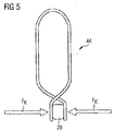
- Figure 5 shows a further variant of a clip 44, which is elastically biased into a clamping position in which it presses the mutually opposite fold walls 26, 28 of the fold 24 against each other.
- the clip 44 shown in Figure 5 can therefore be positioned in a particularly simple and convenient manner.
- the clips 44 shown and described in detail here represent merely preferred embodiments, and that features explained here in connection with individual embodiments may be combined with one another in any manner.
- the clip 44 shown in Figure 4 may be equipped with a dimension defining means 56.
- a magnet arrangement adapted to apply a pressing force F A directed perpendicularly in relation to the support surface 14, onto the film 18 and the sealing tape 20, may also be integrated into a clip 44 illustrated in Figure 3 .
Landscapes
- Engineering & Computer Science (AREA)
- Mechanical Engineering (AREA)
- Chemical & Material Sciences (AREA)
- Composite Materials (AREA)
- Architecture (AREA)
- Civil Engineering (AREA)
- Structural Engineering (AREA)
- Physics & Mathematics (AREA)
- Fluid Mechanics (AREA)
- Casting Or Compression Moulding Of Plastics Or The Like (AREA)
Abstract
In a method for producing a component from a fibre-reinforced composite material, a semifinished product (16), containing reinforcing fibres, is disposed on a support surface (14) of a support (12). The semifinished product (16) is covered with a film (18), the film (18) being draped, in at least one portion, in such a manner that at least one fold (24), extending from the support surface (14) of the support (12), is produced. A sealing tape (20) is applied along an open edge of the fold (24), in order to seal off from the ambient atmosphere a space (19) defined by the support surface (14) and the film (18), in the region of the fold (24), such that two mutually opposite fold walls (26, 28) of the fold (24) are formed partly by the film (18) and partly by the sealing tape (20). A clip (44) is applied over the fold (24) in such a manner that the clip (44) applies a clamping force (FK), which presses the mutually opposite fold walls (26, 28) of the fold (24) against each other. A vacuum is generated in the space (19) defined by the support surface (14) of the support (12) and the film (18).
Description
- The invention relates to a method and an apparatus for producing a component, in particular an aircraft structural component, from a fibre-reinforced composite material, in which use is made of a structure that comprises a mould for receiving a semifinished product, a semifinished product, and a vacuum film for sealing off the semifinished product from the ambient atmosphere.
- In aircraft construction, efforts are increasingly being made to use components composed entirely or partially of fibre-reinforced composite materials, for example glass-fibre or carbon-fibre reinforced plastics. For example,
DE 10 2007 062 111 A1 describes a crossmember structure, composed of carbon-fibre reinforced plastic, which serves to support the individual panels of an aircraft floor system for separating a passenger cabin from a cargo compartment disposed beneath the passenger cabin. It is additionally known, for example fromDE 10 2004 001 078 A1 orCN 100418850 , to provide aircraft fuselage segments with a skin and reinforcing elements (e.g. bulkheads, stringers) of fibre-reinforced composite materials. - Aircraft structural components of fibre-reinforced composite materials may be produced according to a vacuum infusion method or a vacuum-assisted resin transfer moulding (RTM) method, in which a moulding of individual fibres, fibre prewovens or fibre prepregs of an existing semifinished product is disposed in or on a mould, and the semifinished product is then sealed off from the ambient atmosphere by means of a vacuum film. A hardenable plastic material such as, for example, an epoxy resin material, is then injected into the semifinished product through infusion hoses, which are connected to couplings that extend through the vacuum film in a sealed manner. The hardenable plastic material injected into the semifinished product is finally hardened under elevated pressure and/or elevated temperature, so as to obtain a composite material that contains reinforcing fibres embedded in a matrix composed of the hardened plastic material. For this purpose, the structure comprising the mould, the semifinished product and the vacuum film may be put into an autoclave.
- The invention is directed towards the object of specifying a method and an apparatus that make it possible to produce, in a reproducible manner and with uniformly high quality, a component, in particular an aircraft structural component, from a fibre-reinforced composite material by use of a structure that comprises a mould for receiving a semifinished product, a semifinished product, and a vacuum film for sealing off the semifinished product from the ambient atmosphere.
- This object is achieved by a method having the features of Claim 1 and by an apparatus having the features of Claim 9.
- In a method for manufacturing a component from a fibre-reinforced composite material, a semifinished product, containing reinforcing fibres, is disposed on a support surface of a support. The reinforcing fibres contained in the semifinished product may exist in the form of individual fibres or in the form of a fibre laying or fibre textile and be realized, for example, in the form of carbon fibres. Further, in addition to reinforcing fibres, the semifinished product may contain a plastic material. The plastic material may be, for example, a thermoplastic plastic material or a hardenable plastic material. For example, the semifinished product may contain a hardenable resin material, in particular an epoxy resin. In a preferred embodiment of the method, the semifinished product is realized in the form of a fibre prepreg, which comprises a textile or laying of reinforcing fibres provided with a surface coating of a hardenable plastic material.
- A design of the support surface of the support is preferably matched to a design of the semifinished product carried on the support surface. For example, the support surface may be curved if the semifinished product is also of a curved design, this being the case, for example, if the semifinished product has a curved portion intended for production of a portion of an aircraft fuselage shell. In addition, the support surface may constitute a part of a surface of a recessed mould, in which the semifinished product can be disposed or accommodated.
- The semifinished product disposed on the support surface of the support is covered with a film. The film is preferably a vacuum film, which is suitable for sealing off a space, enclosed by the film, from the ambient atmosphere. In at least one portion, the film is draped in such a manner that at least one fold, extending from the support surface of the support, is produced. If desired, a plurality of folds may be draped into the film. The at least one fold serves to avoid unwanted stresses in the film in the region of changes in the geometry of the semifinished product. In addition, allowance is also made for an amount of oversize of the film, by the formation of at least one fold, preferably in the region of an edge of the semifinished product.
- A sealing tape is applied along an open edge of the fold, in order to seal off from the ambient atmosphere a space defined by the support surface and the film, in the region of the fold. This results in regions in which the sealing tape lies on the film, and in regions in which portions of the sealing tape lie on one another. Two mutually opposite fold walls of the fold are thus formed partly by the film and partly by the sealing tape. The sealing tape is preferably provided with an adhesive layer in the region of at least one surface, i.e. realized as a single-sided or double-sided self-adhesive sealing tape. The sealing tape may be pressed on, for example, manually or by means of a so-called roller applicator.
- A clip is then applied over the fold in such a manner that the clip applies a clamping force, which presses the mutually opposite fold walls of the fold against each other. The clamping force applied by the clip thus counteracts separation of the sealing tape from the film and, in particular, separation of two sealing tape portions that are adhesively bonded to each other.
- Finally, a vacuum is generated in the space defined by the support surface of the support and the film. In other words, a pressure that is less than the pressure of the ambient atmosphere surrounding the structure comprising the support, the semifinished product and the film is generated in the space defined by the support surface of the support and the film. For this purpose, the space defined by the support surface of the support and the film may be connected to a suitable vacuum source, for example a pump. The pump may be connected, for example, to a coupling that extends through the film in a sealed manner.
- When the required reduced pressure is present in the space defined by the support surface of the support and the film, a plastic material, preferably a hardenable plastic material, may be injected, if required, into the semifinished product. The vacuum then ensures a rapid and uniform distribution of the plastic material in the semifinished product. Additionally or alternatively, the support, with the semifinished product and the film, may be put into an oven or autoclave to harden plastic material contained in the semifinished product, and treated therein under elevated temperature and/or elevated pressure. As the vacuum is generated in the space defined by the support surface of the support and the film, the at least one fold deforms, since the film portion forming the fold is sucked in the direction of the support surface of the support. Consequently, stress peaks occur, particularly in a region of the sealing tape, used for sealing the fold, that is adjacent to the support surface of the support, which stress peaks may result in absence of seal tightness. Moreover, movements of the fold that are induced by an airflow in an oven or autoclave may result in absence of seal tightness in the region of the sealing tape. Finally, thermal stresses produced during heat treatment of the structure comprising the support, the film and the semifinished product may also cause leakages in the region of the sealing tape.
- The clip used in the method for producing a component from a fibre-reinforced composite material, as a result of the clamping force that it applies to press the mutually opposite fold walls of the fold against each other, counteracts stretching of the sealing tape in the edge region of the fold as the fold deforms. In the case of the method for producing a component from a fibre-reinforced composite material, the risk of absence of seal tightness, or leakages, in the region of the sealing tape is thus significantly reduced by the use of the clip. The clip thus makes it possible, in a comparatively inelaborate manner, to make the component production process significantly more robust.
- The clip may be applied over the fold in such a manner that the clamping force applied by the clip presses the mutually opposite fold walls against each other in a region adjacent to the support surface of the support. The clip then counteracts stretching of the sealing tape precisely in the region of the fold walls in which stress peaks occur as the fold deforms, and which are therefore particularly susceptible to the occurrence of leakages.
- The clip may comprise two mutually opposite limbs. The limbs of the clip may be connected to each other at their first ends and, at least in the region of their second ends opposite to the first ends, may each provided with a clamping portion for applying the clamping force to the mutually opposite fold walls of the fold. The clamping portions provided on the limbs of the clip may extend over merely a portion of the limbs, in the region of the second ends of the limbs. Such a design of the clip is appropriate, in particular, if the clip is intended to press the mutually opposite fold walls against each other only in a region adjacent to the support surface of the support. Alternatively, however, the clip may also have clamping portions that extend over the entire length of the limbs or over a significant part of the length of the limbs. The clip is then suitable for pressing the mutually opposite fold walls against each other also in a region spaced from the support surface of the support.
- The clip may be elastically biased into a clamping position in which it presses the mutually opposite fold walls of the fold against each other. Alternatively, however, it is also possible to design the clip such that it must be manually pushed into its clamping position in which it presses the mutually opposite fold walls of the fold against each other. If desired, the clamp may comprise a locking device for locking the clip in a clamping position in which it presses the mutually opposite fold walls of the fold against each other. The clip can then be held in its clamping position in a particularly stable manner. For example, the clip may be realized in the form of a screw clamp, a latch, or the like. The clip may be realized as an injection moulded part or as a metal part.
- In a preferred embodiment of the method for producing a component from a fibre-reinforced composite material, the clip is fastened to the support surface of the support by means of a fastening means. The clip is thereby prevented from tilting in an unwanted manner relative to the support surface of the support. In particular, the fastening means may be adapted to apply a pressing force, directed in the direction of the support surface of the support, onto the film and/or onto the sealing tape. Separation of the sealing tape and/or of the film from the support surface of the support is thereby counteracted. The fastening means may comprise, for example, a magnet arrangement, which acts in combination with a support composed of a magnetic material, for example a ferromagnetic material, in order to hold the clip in a desired position relative to the support surface of the support. Additionally or alternatively, the fastening means may comprise a holding device, which encompasses an edge of the support in order to fix the clip in its position relative to the support surface of the support. Such a holding device may than also be used to fix the clip in its position relative to the support surface of the support if the support is not composed of a magnetic material.
- A dimension of the fold in a direction perpendicular to the support surface of the support may be set by means of a dimension defining means of the clamp. The dimension defining means may comprise, for example, a link extending between two mutually opposite limbs of the clip. For example, the fold may be draped in such a manner that the fold extends, starting from the support surface to the support, to the link provided between the limbs of the clip. The clip can thus be used to define a required shape of the fold. This makes it possible to design even a manual draping operation in a relatively reproducible manner.
- In a preferred embodiment of the method, differing dimensions of a plurality of folds in the direction perpendicular to the support surface of the support are set by means of the dimension defining means of a plurality of differently shaped clips. The clips may differ, for example, in respect of the length of their limbs and/or the positioning of the dimension defining means comprising, for example, a link extending between the limbs, relative to the limbs. Moreover, if desired, the clips may be realized in a multiplicity of colours, or may be appropriately marked, in order to render suitable clips immediately identifiable for the production of differently shaped folds. This further increases the reproducibility of the process, and further simplifies the process as a whole.
- The film may be provided with at least one position marking for marking a position and/or a dimension of the at least one fold to be draped. The position marking makes it possible to define the position and the shape of the fold in a comparatively precise and reproducible manner, even in the case of a manual draping operation. If desired, the film may be provided with a plurality of position markings for marking the positions and/or dimensions of a plurality of folds to be draped.
- An apparatus for producing a component from a fibre-reinforced composite material comprises a support, having a support surface for disposing a semifinished product containing reinforcing fibres. The apparatus additionally comprises a film for covering the semifinished product, the film being adapted to be draped, in at least one portion, in such a manner that at least one fold, extending from the support surface of the support, is produced. A sealing tape of the apparatus is adapted to be applied along an open edge of the fold, in order to seal off from the ambient atmosphere a space defined by the support surface and the film, in the region of the fold, such that two mutually opposite fold walls of the fold are formed partly by the film and partly by the sealing tape. The apparatus additionally comprises a clip, which is adapted to be applied over the fold in such a manner that the clip applies a clamping force, which presses the mutually opposite fold walls of the fold against each other. Finally, the device comprises a vacuum generating means for generating a vacuum in the space defined by the support surface of the support and the film.
- In a preferred embodiment of the apparatus, the clip is adapted to be applied over the fold in such a manner that the clamping force applied by the clip presses the mutually opposite fold walls against each other in a region adjacent to the support surface of the support.
- The clip may comprise two mutually opposite limbs, which are connected to each other at their first ends and which, at least in the region of their second ends opposite to the first ends, are each provided with a clamping portion for applying the clamping force to the mutually opposite fold walls of the fold.
- The clip may be elastically biased into a clamping position in which it presses the mutually opposite fold walls of the fold against each other. Additionally or alternatively, the clip may comprise a locking device for locking the clip in a clamping position in which it presses the mutually opposite fold walls of the fold against each other.
- The clip may be fastened to the support surface of the support by means of a fastening means. The fastening means may be adapted to apply a pressing force, directed perpendicularly in relation to the support surface, onto the film and/or onto the sealing tape. The fastening means may comprise a magnet arrangement and/or a holding device, which encompass/encompasses an edge of the support.
- Further, the clip may be equipped with a dimension defining means, which is adapted to set a dimension of the fold in a direction perpendicular to the support surface of the support. The dimension defining means may comprise a link extending between two mutually opposite limbs of the clip.
- In a preferred embodiment, the apparatus comprises a plurality of differently shaped clips, which are adapted to set, by means of their respective dimension defining means, differing dimensions of a plurality of folds in the direction perpendicular to the support surface of the support.
- The film may be provided with at least one position marking for marking a position and/or a dimension of the at least one fold to be draped.
- Preferred embodiments of the invention are now explained in greater detail with reference to the appended schematic drawings, of which
- Figure 1
- shows an apparatus for producing a component from a fibre-reinforced composite material,
- Figure 2
- shows a detail representation of a fold draped into a film of the apparatus according to
Figure 1 , - Figure 3
- shows the fold according to
Figure 2 with a clip applied over the fold, - Figure 4
- shows the fold according to
Figure 2 with an alternative clip applied over the fold, and - Figure 5
- shows the fold according to
Figure 2 with a further alternative clip applied over the fold. - An
apparatus 10, shown inFigure 1 , for producing a component, in particular an aircraft structural component, from a fibre-reinforced composite material comprises asupport 12 having asupport surface 14. Asemifinished product 16 containing reinforcing fibres can be disposed on thesupport surface 14 of thesupport 12. The exemplarysemifinished product 16 shown inFigure 1 is a fibre prepreg, which comprises a woven fabric or laying of reinforcing fibres, in particular carbon fibres, which have been provided with a surface coating of a hardenable plastic material, in particular an epoxy resin. Thesemifinished product 16 is intended to be processed further to form an aircraft structural component that comprises an aircraft outer-skin portion and primary structural elements such as, for example, stringers, that are connected to the aircraft outer-skin portion. - The
semifinished product 16 is covered with afilm 18. Thefilm 18 is realized in the form of a vacuum film that is suitable for sealing off aspace 19, which is delimited by thesupport surface 14 and thefilm 18 and in which thesemifinished product 16 is accommodated, from the ambient atmosphere. In the region of its edges, thefilm 18 is adhesive-bonded to thesupport surface 14 by means of a sealingtape 20 provided with an adhesive layer on both sides. - In the region of changes in the geometry of the
semifinished product 16, portions of thefilm 18 are draped in such a manner that a plurality offolds 22 are formed. These folds 22 prevent the formation of unwanted stresses in thefilm 18. In addition, allowance is also made for an amount of oversize of thefilm 18, by the formation offolds 24 disposed in the region of an edge of thesemifinished product 16. The folds 22, 24 each extend upwardly from thesupport surface 14 of thesupport 12. In order to facilitate the draping of thefolds film 18, the film is provided withposition markings 25 for marking the positions of thefolds space 19 defined by thesupport surface 14 and thefilm 18 to be sealed off from the ambient atmosphere in the region of thefolds tape 20 is applied along an open edge of eachfold Figure 2 . Mutually opposite foldwalls folds film 18 and partly by the sealingtape 20. - The
apparatus 10 additionally comprises a vacuum generating means 30, which may be realized, for example, in the form of a pump. The vacuum generating means 30 serves to generate a vacuum, i.e. a pressure that is reduced in respect of the ambient pressure, in thespace 19 defined by thesupport surface 14 of thesupport 12 and thefilm 18. Finally, theapparatus 10 is equipped with aninjection device 32, which serves to inject a hardenable plastic material, for example an epoxy resin, into thesemifinished product 16. Theinjection device 32 comprises aplastic material reservoir 34, which is connected, via corresponding connectinghoses 36, 38, to correspondingcouplings 40, 42, that extend through thefilm 18 in a sealed manner. - When a pressure, generated by means of the vacuum generating means 30, that is less than the ambient pressure prevails in the
space 19 accommodating thesemifinished product 16, plastic material injected by means of theinjection device 32 is distributed rapidly and uniformly in thesemifinished product 16. For the purpose of hardening the plastic material, which is present in any case in thesemifinished product 16 realized in the form of a prepreg, and the plastic material injected into thesemifinished product 16, the structure comprising thesupport 12, thesemifinished product 16 and thefilm 18 can be subjected to an elevated pressure and/or elevated temperature in an oven or autoclave (not shown in the figures). - As the vacuum is generated in the
space 19 defined by thesupport surface 14 of thesupport 12 and thefilm 18, thefolds folds support surface 14. In addition, thefolds semifinished product 16 and/or injected into thesemifinished product 16. Finally, thermal stresses may occur during a heat treatment of the structure comprising thesupport 12, thefilm 18 and thesemifinished product 16. Consequently, stress peaks occur, particularly in regions of the sealingtape 20, used for sealing thefolds support surface 14, which stress peaks may result in absence of seal tightness. This so-called "critical region" is identified inFigure 2 by the reference K. - The
apparatus 10 therefore additionally comprises a plurality ofclips 44, which are applied over each fold 24 in such a manner that the mutuallyopposite fold walls folds 24, which are formed partly by thefilm 18 and partly by the sealingtape 20, are pressed against each other by a clamping force FK applied by theclips 44, seeFigure 3 . In the case of deformation of thefold 24 subjected to the clamping force FK applied by theclamp 44, the clamping force FK applied by eachclip 44 counteracts stretching of the sealingtape 20 in the edge region of thefold 24. The risk of absence of seal tightness, or leakages, in the region of the sealingtape 20 is thereby significantly reduced. - The
clip 44 illustrated inFigure 3 comprises two mutuallyopposite limbs limbs clip 44 are each provided with a clampingportion portions clip 44 applies the clamping force FK to a region of the mutuallyopposite fold walls support surface 14 of thesupport 12, i.e. to the critical region K subjected to the stress peaks. - The
clip 44 shown inFigure 3 comprises a locking device 54 (indicated in schematic form only inFigure 3 ), which enables theclip 44 to be held securely in a clamping position in which it presses the mutuallyopposite fold walls fold 24 against each other. Furthermore, theclip 44 is provided with a fastening means 55, indicated only by a broken line inFigure 3 , for fastening theclip 44 to thesupport surface 14 of thesupport 12. The fastening means 55 comprises a holdingdevice 57, which encompasses an edge of thesupport 12 and thereby fixes theclip 44 securely relative to thesupport surface 14 of thesupport 12. - The
clip 44 additionally comprises adimension defining means 56. In the embodiment shown inFigure 3 , the dimension defining means 56 comprises alink 58, which extends between the two mutuallyopposite limbs clip 44. Thefold 24 can then be draped such that thefold 24 extends, starting from the support surface 14 o thesupport 12, to thelink 58 provided between thelimbs clip 44. The clip can thus be used to define a required shape of thefold 24, and thus to design even a manual draping operation in a relatively reproducible manner. - If a plurality of
folds 24, having differing shapes and/or dimensions, are to be draped into thefilm 18, clips 44 of differing designs may be used. In particular, clips 44 that differ in respect of the length of theirlimbs link 58 extending between thelimbs folds 24 in the direction perpendicular to supportsurface 14 of thesupport 12. If desired, theclips 44 may be realized in a multiplicity of colours, or may be appropriately marked, in order to rendersuitable clips 44 immediately identifiable for the production of differently shaped folds 24. - The
clip 44 illustrated inFigure 4 differs from the clip according toFigure 3 in that it not only applies a clamping force FK to a region of the mutuallyopposite fold walls fold 24 that is adjacent to thesupport surface 14 of thesupport 12, but also presses thefilm 18 and the sealingtap 20 in the region of thefold 24 against thesupport surface 14, i.e. applies a pressing force FA, directed perpendicularly in relation to thesupport surface 14, onto thefilm 18 and the sealingtape 20. For this purpose, the fastening means 55 of theclip 44 comprises amagnet arrangement 60, which acts in combination with thesupport 12 made of a magnetic material, for example a ferromagnetic metal. Theclip 44 thus also counteracts separation of the sealingtape 20, and consequently of thefilm 18, from thesupport surface 14. Depending on its design, the holdingdevice 55 illustrated inFigure 3 that encompasses the edge of thesupport 12 is also suitable to apply such a pressing force FA, directed perpendicularly in relation to thesupport surface 14, onto thefilm 18 and the sealingtape 20. However, a dimension defining means 56, as provided in the case of theclip 44 according toFigure 3 , has been dispensed with in the case of theclip 44 represented inFigure 4 . -
Figure 5 shows a further variant of aclip 44, which is elastically biased into a clamping position in which it presses the mutuallyopposite fold walls fold 24 against each other. Theclip 44 shown inFigure 5 can therefore be positioned in a particularly simple and convenient manner. - It is understood that the
clips 44 shown and described in detail here represent merely preferred embodiments, and that features explained here in connection with individual embodiments may be combined with one another in any manner. Thus, for example, theclip 44 shown inFigure 4 may be equipped with adimension defining means 56. Further, a magnet arrangement adapted to apply a pressing force FA, directed perpendicularly in relation to thesupport surface 14, onto thefilm 18 and the sealingtape 20, may also be integrated into aclip 44 illustrated inFigure 3 .
Claims (15)
- Method for producing a component from a fibre-reinforced composite material, comprising the steps:- disposing a semifinished product (16), containing reinforcing fibres, on a support surface (14) of a support (12),- covering the semifinished product (16) with a film (18), the film (18) being draped, in at least one portion, in such a manner that at least one fold (24), extending from the support surface (14) of the support (12), is produced,- applying a sealing tape (20) along an open edge of the fold (24), in order to seal off from the ambient atmosphere a space (19) defined by the support surface (14) and the film (18), in the region of the fold (24), such that two mutually opposite fold walls (26, 28) of the fold (24) are formed partly by the film (18) and partly by the sealing tape (20),- applying a clip (44) over the fold (24) in such a manner that the clip (44) applies a clamping force (FK), which presses the mutually opposite fold walls (26, 28) of the fold (24) against each other, and- generating a vacuum in the space (19) defined by the support surface (14) of the support (12) and the film (18).
- Method according to Claim 1,
the clip (44) being applied over the fold (24) in such a manner that the clamping force (FK) applied by the clip (44) presses the mutually opposite fold walls (26, 28) against each other in a region adjacent to the support surface (14) of the support (12). - Method according to Claim 1 or 2,
the clip (44) comprising two mutually opposite limbs (46, 48), which are connected to each other at their first ends and which, at least in the region of their second ends opposite to the first ends, are each provided with a clamping portion (50, 52) for applying the clamping force (FK) to the mutually opposite fold walls (26, 28) of the fold (24). - Method according to any one of Claims 1 to 3,
the clip (44) being elastically biased into a clamping position in which it presses the mutually opposite fold walls (26, 28) of the fold (24) against each other, and/or the clip (44) comprising a locking device (54) for locking the clip (44) in a clamping position in which it presses the mutually opposite fold walls (26, 28) of the fold (24) against each other. - Method according to any one of Claims 1 to 4,
the clip (44) being fastened to the support surface (14) of the support (12) by means of a fastening means (55), which preferably applies a pressing force (FA), directed perpendicularly in relation to the support surface (14), onto at least one of the film (18) and the sealing tape (20), and which, in particular, comprises at least one of a magnet arrangement (60) and a holding device (57), which encompasses an edge of the support (12). - Method according to any one of Claims 1 to 5,
a dimension of the fold (24) in a direction perpendicular to the support surface (14) of the support (12) being set by means of a dimension defining means (56) of the clip (44) that, in particular, comprises a link (58) extending between two mutually opposite limbs (46, 48) of the clip (44). - Method according to Claim 6,
differing dimensions of a plurality of folds (24) in the direction perpendicular to the support surface (14) of the support (12) being set by means of the dimension defining means (56) of a plurality of differently shaped clips (44). - Method according to any one of Claims 1 to 6,
the film (18) being provided with at least one position marking for marking at least one of a position and a dimension of the at least one fold (24) to be draped. - Apparatus (10) for producing a component from a fibre-reinforced composite material, which comprises:- a support (12), having a support surface (14) for disposing a semifinished product (16) containing reinforcing fibres,- a film (18) for covering the semifinished product (16), the film (18) being adapted to be draped, in at least one portion, in such a manner that at least one fold (24), extending from the support surface (14) of the support (12), is produced,- a sealing tape (20), which is adapted to be applied along an open edge of the fold (24), in order to seal off from the ambient atmosphere a space (19) defined by the support surface (14) and the film (18), in the region of the fold (24), such that two mutually opposite fold walls (26, 28) of the fold (24) are formed partly by the film (18) and partly by the sealing tape (20),- a clip (44), which is adapted to be applied over the fold (24) in such a manner that the clip (44) applies a clamping force (FK), which presses the mutually opposite fold walls (26, 28) of the fold (24) against each other, and- a vacuum generating means (30) for generating a vacuum in the space (19) defined by the support surface (14) of the support (12) and the film (18).
- Apparatus according to Claim 9,
the clip (44) being adapted to be applied over the fold (24) in such a manner that the clamping force (FK) applied by the clip (44) presses the mutually opposite fold walls (26, 28) against each other in a region adjacent to the support surface (14) of the support (12). - Apparatus according to Claim 9 or 10,
the clip (44) comprising two mutually opposite limbs (46, 48), which are connected to each other at their first ends and which, at least in the region of their second ends opposite to the first ends, are each provided with a clamping portion (50, 52) for applying the clamping force (FK) to the mutually opposite fold walls (26, 28) of the fold (24). - Apparatus according to any one of Claims 9 to 11,
the clip (44) being elastically biased into a clamping position in which it presses the mutually opposite fold walls (26, 28) of the fold (24) against each other, and/or the clip (44) comprising a locking device (54) for locking the clip (44) in a clamping position in which it presses the mutually opposite fold walls (26, 28) of the fold (24) against each other. - Apparatus according to any one of Claims 9 to 12,
the clip (44) being fastened to the support surface (14) of the support (12) by means of a fastening means (55), the fastening means (55) preferably being adapted to apply a pressing force (FA), directed perpendicularly in relation to the support surface (14), onto at least one of the film (18) and the sealing tape (20), and comprising, in particular, at least one of a magnet arrangement (60) and a holding device (57), which encompasses an edge of the support (12),
and/or
the clip (44) comprising a dimension defining means (56), which is adapted to set a dimension of the fold (24) in a direction perpendicular to the support surface (14) of the support (12) and which, in particular, comprises a link (58) extending between two mutually opposite limbs (46, 48) of the clip (44). - Apparatus according to Claim 13,
the apparatus (10) comprising a plurality of differently shaped clips (44), which are adapted to set, by means of their respective dimension defining means (56), differing dimensions of a plurality of folds (24) in the direction perpendicular to the support surface (14) of the support (12). - Apparatus according to any one of Claims 9 to 14,
the film (18) being provided with at least one position marking for marking at least one of a position and a dimension of the at least one fold (24) to be draped.
Applications Claiming Priority (1)
| Application Number | Priority Date | Filing Date | Title |
|---|---|---|---|
| DE102015211671.9A DE102015211671A1 (en) | 2015-06-24 | 2015-06-24 | Method and device for producing a component using a vacuum film |
Publications (1)
| Publication Number | Publication Date |
|---|---|
| EP3112118A1 true EP3112118A1 (en) | 2017-01-04 |
Family
ID=55862590
Family Applications (1)
| Application Number | Title | Priority Date | Filing Date |
|---|---|---|---|
| EP16167386.8A Withdrawn EP3112118A1 (en) | 2015-06-24 | 2016-04-28 | Method and apparatus for producing a component by use of a vacuum film |
Country Status (3)
| Country | Link |
|---|---|
| US (1) | US20160375670A1 (en) |
| EP (1) | EP3112118A1 (en) |
| DE (1) | DE102015211671A1 (en) |
Cited By (1)
| Publication number | Priority date | Publication date | Assignee | Title |
|---|---|---|---|---|
| FR3092785A1 (en) * | 2019-02-19 | 2020-08-21 | Airbus Operations | method of forming a vacuum bagging film comprising the formation of ribs by buckling the film |
Citations (7)
| Publication number | Priority date | Publication date | Assignee | Title |
|---|---|---|---|---|
| WO2002058916A1 (en) * | 2001-01-25 | 2002-08-01 | Quickstep Technologies Pty, Ltd. | Composite and metal component production, forming and bonding system |
| DE102004001078A1 (en) | 2004-01-05 | 2005-07-28 | Airbus Deutschland Gmbh | Aircraft fuselage outer skin is a composite sandwich structure of carbon fiber, glass fiber, ceramic fibers, aluminium or titanium alloys |
| DE102007062111A1 (en) | 2007-12-21 | 2009-07-02 | Airbus Deutschland Gmbh | Shielding arrangement for lightning protection of e.g. electrical conductor, in aircraft, has installation space protectively arranged in region of floor framework, and delimitation surface provided with electrical conducting shield |
| WO2010094808A2 (en) * | 2009-02-23 | 2010-08-26 | Airbus Operations Gmbh | Method for at least partially remachining or replacing a reinforcement element of a fibre composite structure and associated connecting device |
| EP2428352A1 (en) * | 2010-09-13 | 2012-03-14 | Premium AEROTEC GmbH | Vacuum assembly for pressurising a component during its production and method for producing a component |
| US20120152461A1 (en) * | 2007-12-20 | 2012-06-21 | Airbus Operations Gmbh | Method for reinforcing a fibre composite component and a vacuum mat and arrangement for producing a reinforced fibre composite component |
| EP2508326A1 (en) * | 2011-04-05 | 2012-10-10 | The Boeing Company | Method and apparatus for making contoured composite stiffeners |
Family Cites Families (6)
| Publication number | Priority date | Publication date | Assignee | Title |
|---|---|---|---|---|
| DK176296B1 (en) * | 2005-11-14 | 2007-06-18 | Lm Glasfiber As | Preparation of laminate by resin injection |
| US8034278B2 (en) * | 2006-01-13 | 2011-10-11 | Hexcel Corporation | Pressurized molding of composite parts |
| FR2936442B1 (en) * | 2008-09-30 | 2013-03-08 | Airbus France | DEVICE FOR MANUFACTURING A COMPOUND COMPOSITE MATERIAL PART. |
| DE102008054544B4 (en) * | 2008-12-11 | 2014-03-06 | Airbus Operations Gmbh | Method for producing a plastic film tube and a corresponding plastic film tube |
| DE102010040970A1 (en) * | 2010-09-17 | 2012-03-22 | Airbus Operations Gmbh | Method and apparatus for providing a dry textile preform |
| DK2441951T3 (en) * | 2010-10-13 | 2017-07-10 | Siemens Ag | Process for manufacturing a wind turbine rotor blade |
-
2015
- 2015-06-24 DE DE102015211671.9A patent/DE102015211671A1/en not_active Withdrawn
-
2016
- 2016-04-28 EP EP16167386.8A patent/EP3112118A1/en not_active Withdrawn
- 2016-06-22 US US15/189,208 patent/US20160375670A1/en not_active Abandoned
Patent Citations (8)
| Publication number | Priority date | Publication date | Assignee | Title |
|---|---|---|---|---|
| WO2002058916A1 (en) * | 2001-01-25 | 2002-08-01 | Quickstep Technologies Pty, Ltd. | Composite and metal component production, forming and bonding system |
| DE102004001078A1 (en) | 2004-01-05 | 2005-07-28 | Airbus Deutschland Gmbh | Aircraft fuselage outer skin is a composite sandwich structure of carbon fiber, glass fiber, ceramic fibers, aluminium or titanium alloys |
| CN100418850C (en) | 2004-01-05 | 2008-09-17 | 空中客车德国有限公司 | Fuselage body |
| US20120152461A1 (en) * | 2007-12-20 | 2012-06-21 | Airbus Operations Gmbh | Method for reinforcing a fibre composite component and a vacuum mat and arrangement for producing a reinforced fibre composite component |
| DE102007062111A1 (en) | 2007-12-21 | 2009-07-02 | Airbus Deutschland Gmbh | Shielding arrangement for lightning protection of e.g. electrical conductor, in aircraft, has installation space protectively arranged in region of floor framework, and delimitation surface provided with electrical conducting shield |
| WO2010094808A2 (en) * | 2009-02-23 | 2010-08-26 | Airbus Operations Gmbh | Method for at least partially remachining or replacing a reinforcement element of a fibre composite structure and associated connecting device |
| EP2428352A1 (en) * | 2010-09-13 | 2012-03-14 | Premium AEROTEC GmbH | Vacuum assembly for pressurising a component during its production and method for producing a component |
| EP2508326A1 (en) * | 2011-04-05 | 2012-10-10 | The Boeing Company | Method and apparatus for making contoured composite stiffeners |
Cited By (1)
| Publication number | Priority date | Publication date | Assignee | Title |
|---|---|---|---|---|
| FR3092785A1 (en) * | 2019-02-19 | 2020-08-21 | Airbus Operations | method of forming a vacuum bagging film comprising the formation of ribs by buckling the film |
Also Published As
| Publication number | Publication date |
|---|---|
| DE102015211671A1 (en) | 2016-12-29 |
| US20160375670A1 (en) | 2016-12-29 |
Similar Documents
| Publication | Publication Date | Title |
|---|---|---|
| RU2697451C2 (en) | Composite article manufacturing method | |
| EP2318198B1 (en) | Method of assembling and shaping laminate panel and apparatus therefore | |
| CA2987004C (en) | Device and method for manufacturing fiber-reinforced plastic molded article | |
| US10016949B2 (en) | Method of moulding a charge | |
| US7293737B2 (en) | Co-cured stringers and associated mandrel and fabrication method | |
| US6355133B1 (en) | Forming reinforcing components | |
| EP2116358B1 (en) | Method and apparatus for conforming a blank | |
| US7922957B2 (en) | Method for forming composite components and tool for use therein | |
| US9637215B2 (en) | Pressure bulkhead for an aircraft and device as well as method for manufacturing an aircraft structural component | |
| JPH10146898A (en) | Molding method of fiber reinforced composite material | |
| US9815246B2 (en) | Supporting profiled element, method for producing a supporting profiled element, and use of said supporting profiled element in a method for producing a reinforced vehicle fuselage component | |
| RU2647031C1 (en) | Equipment for forming fibro-reinforced plastics and method for forming structure of fibro-reinforced plastics | |
| US20160176085A1 (en) | Method and system for producing composite structures | |
| US20140186574A1 (en) | Method for producing and connecting fibre-reinforced components and aircraft or spacecraft | |
| CA2935481C (en) | Frp shaping jig and method of shaping frp structure | |
| CN108712951B (en) | Method for producing composite material | |
| US20160375670A1 (en) | Method and apparatus for producing a component by use of a vacuum film | |
| US10882263B2 (en) | Method for impregnating a preform with resin utilizing a caul plate having a channel for distributing resin | |
| US10661507B2 (en) | Assembly having individual components made of a fibre-reinforced composite material | |
| JP2021030729A (en) | Highly contoured composite structures and system and method for making the same | |
| US20140158282A1 (en) | device for the manufacture of a bonded component from fibre-reinforced plastics, and also a method | |
| US20190106225A1 (en) | Vacuum film with ventilation | |
| US12496786B2 (en) | Forming method | |
| DE102016111073A1 (en) | Mold element and method for the vacuum-assisted processing of a semi-finished fiber product | |
| DE102016111074A1 (en) | Gas guide arrangement and method for the vacuum-assisted processing of a semi-finished fiber product |
Legal Events
| Date | Code | Title | Description |
|---|---|---|---|
| PUAI | Public reference made under article 153(3) epc to a published international application that has entered the european phase |
Free format text: ORIGINAL CODE: 0009012 |
|
| STAA | Information on the status of an ep patent application or granted ep patent |
Free format text: STATUS: REQUEST FOR EXAMINATION WAS MADE |
|
| 17P | Request for examination filed |
Effective date: 20160428 |
|
| AK | Designated contracting states |
Kind code of ref document: A1 Designated state(s): AL AT BE BG CH CY CZ DE DK EE ES FI FR GB GR HR HU IE IS IT LI LT LU LV MC MK MT NL NO PL PT RO RS SE SI SK SM TR |
|
| AX | Request for extension of the european patent |
Extension state: BA ME |
|
| STAA | Information on the status of an ep patent application or granted ep patent |
Free format text: STATUS: THE APPLICATION IS DEEMED TO BE WITHDRAWN |
|
| 18D | Application deemed to be withdrawn |
Effective date: 20170705 |