EP3112113A1 - Method for separating tire - Google Patents
Method for separating tire Download PDFInfo
- Publication number
- EP3112113A1 EP3112113A1 EP15756017.8A EP15756017A EP3112113A1 EP 3112113 A1 EP3112113 A1 EP 3112113A1 EP 15756017 A EP15756017 A EP 15756017A EP 3112113 A1 EP3112113 A1 EP 3112113A1
- Authority
- EP
- European Patent Office
- Prior art keywords
- tire
- frame member
- tire frame
- dismantling
- thermoplastic resin
- Prior art date
- Legal status (The legal status is an assumption and is not a legal conclusion. Google has not performed a legal analysis and makes no representation as to the accuracy of the status listed.)
- Granted
Links
- 238000000034 method Methods 0.000 title claims abstract description 73
- 239000005060 rubber Substances 0.000 claims abstract description 47
- 229920005992 thermoplastic resin Polymers 0.000 claims abstract description 47
- 229920001971 elastomer Polymers 0.000 claims abstract description 46
- 238000005520 cutting process Methods 0.000 claims abstract description 12
- 238000004073 vulcanization Methods 0.000 claims abstract description 7
- 230000003014 reinforcing effect Effects 0.000 claims description 32
- 239000011324 bead Substances 0.000 claims description 26
- 238000003825 pressing Methods 0.000 claims description 10
- 238000000605 extraction Methods 0.000 claims description 4
- 239000000463 material Substances 0.000 abstract description 19
- 239000002184 metal Substances 0.000 description 23
- 238000000926 separation method Methods 0.000 description 14
- 229910000831 Steel Inorganic materials 0.000 description 6
- 239000010959 steel Substances 0.000 description 6
- 238000004064 recycling Methods 0.000 description 5
- 239000012815 thermoplastic material Substances 0.000 description 5
- 230000006835 compression Effects 0.000 description 4
- 238000007906 compression Methods 0.000 description 4
- 238000000465 moulding Methods 0.000 description 4
- 229920001169 thermoplastic Polymers 0.000 description 4
- 238000003466 welding Methods 0.000 description 4
- 239000000835 fiber Substances 0.000 description 3
- 230000001105 regulatory effect Effects 0.000 description 3
- 239000004416 thermosoftening plastic Substances 0.000 description 3
- 238000001746 injection moulding Methods 0.000 description 2
- 229920005672 polyolefin resin Polymers 0.000 description 2
- 229920005989 resin Polymers 0.000 description 2
- 239000011347 resin Substances 0.000 description 2
- 229920002725 thermoplastic elastomer Polymers 0.000 description 2
- 241000251468 Actinopterygii Species 0.000 description 1
- BZHJMEDXRYGGRV-UHFFFAOYSA-N Vinyl chloride Chemical compound ClC=C BZHJMEDXRYGGRV-UHFFFAOYSA-N 0.000 description 1
- 238000005266 casting Methods 0.000 description 1
- 150000001875 compounds Chemical class 0.000 description 1
- 238000007796 conventional method Methods 0.000 description 1
- 230000000694 effects Effects 0.000 description 1
- 238000003754 machining Methods 0.000 description 1
- 238000004519 manufacturing process Methods 0.000 description 1
- 235000013372 meat Nutrition 0.000 description 1
- 238000002844 melting Methods 0.000 description 1
- 230000008018 melting Effects 0.000 description 1
- 239000004033 plastic Substances 0.000 description 1
- 229920003023 plastic Polymers 0.000 description 1
- 229920006122 polyamide resin Polymers 0.000 description 1
- 229920001225 polyester resin Polymers 0.000 description 1
- 239000004645 polyester resin Substances 0.000 description 1
- 229920000642 polymer Polymers 0.000 description 1
- 239000002861 polymer material Substances 0.000 description 1
- 229920005990 polystyrene resin Polymers 0.000 description 1
- 239000000843 powder Substances 0.000 description 1
- 239000012779 reinforcing material Substances 0.000 description 1
- 239000000243 solution Substances 0.000 description 1
- 239000000126 substance Substances 0.000 description 1
- 229920002803 thermoplastic polyurethane Polymers 0.000 description 1
- 239000013585 weight reducing agent Substances 0.000 description 1
Images




Classifications
-
- B—PERFORMING OPERATIONS; TRANSPORTING
- B29—WORKING OF PLASTICS; WORKING OF SUBSTANCES IN A PLASTIC STATE IN GENERAL
- B29B—PREPARATION OR PRETREATMENT OF THE MATERIAL TO BE SHAPED; MAKING GRANULES OR PREFORMS; RECOVERY OF PLASTICS OR OTHER CONSTITUENTS OF WASTE MATERIAL CONTAINING PLASTICS
- B29B17/00—Recovery of plastics or other constituents of waste material containing plastics
- B29B17/02—Separating plastics from other materials
-
- B—PERFORMING OPERATIONS; TRANSPORTING
- B60—VEHICLES IN GENERAL
- B60C—VEHICLE TYRES; TYRE INFLATION; TYRE CHANGING; CONNECTING VALVES TO INFLATABLE ELASTIC BODIES IN GENERAL; DEVICES OR ARRANGEMENTS RELATED TO TYRES
- B60C5/00—Inflatable pneumatic tyres or inner tubes
- B60C5/01—Inflatable pneumatic tyres or inner tubes without substantial cord reinforcement, e.g. cordless tyres, cast tyres
-
- B—PERFORMING OPERATIONS; TRANSPORTING
- B29—WORKING OF PLASTICS; WORKING OF SUBSTANCES IN A PLASTIC STATE IN GENERAL
- B29B—PREPARATION OR PRETREATMENT OF THE MATERIAL TO BE SHAPED; MAKING GRANULES OR PREFORMS; RECOVERY OF PLASTICS OR OTHER CONSTITUENTS OF WASTE MATERIAL CONTAINING PLASTICS
- B29B17/00—Recovery of plastics or other constituents of waste material containing plastics
- B29B2017/001—Pretreating the materials before recovery
- B29B2017/0021—Dividing in large parts
-
- B—PERFORMING OPERATIONS; TRANSPORTING
- B29—WORKING OF PLASTICS; WORKING OF SUBSTANCES IN A PLASTIC STATE IN GENERAL
- B29B—PREPARATION OR PRETREATMENT OF THE MATERIAL TO BE SHAPED; MAKING GRANULES OR PREFORMS; RECOVERY OF PLASTICS OR OTHER CONSTITUENTS OF WASTE MATERIAL CONTAINING PLASTICS
- B29B17/00—Recovery of plastics or other constituents of waste material containing plastics
- B29B17/02—Separating plastics from other materials
- B29B2017/0203—Separating plastics from plastics
-
- B—PERFORMING OPERATIONS; TRANSPORTING
- B29—WORKING OF PLASTICS; WORKING OF SUBSTANCES IN A PLASTIC STATE IN GENERAL
- B29B—PREPARATION OR PRETREATMENT OF THE MATERIAL TO BE SHAPED; MAKING GRANULES OR PREFORMS; RECOVERY OF PLASTICS OR OTHER CONSTITUENTS OF WASTE MATERIAL CONTAINING PLASTICS
- B29B17/00—Recovery of plastics or other constituents of waste material containing plastics
- B29B17/02—Separating plastics from other materials
- B29B2017/0213—Specific separating techniques
- B29B2017/0217—Mechanical separating techniques; devices therefor
-
- B—PERFORMING OPERATIONS; TRANSPORTING
- B29—WORKING OF PLASTICS; WORKING OF SUBSTANCES IN A PLASTIC STATE IN GENERAL
- B29L—INDEXING SCHEME ASSOCIATED WITH SUBCLASS B29C, RELATING TO PARTICULAR ARTICLES
- B29L2030/00—Pneumatic or solid tyres or parts thereof
-
- Y—GENERAL TAGGING OF NEW TECHNOLOGICAL DEVELOPMENTS; GENERAL TAGGING OF CROSS-SECTIONAL TECHNOLOGIES SPANNING OVER SEVERAL SECTIONS OF THE IPC; TECHNICAL SUBJECTS COVERED BY FORMER USPC CROSS-REFERENCE ART COLLECTIONS [XRACs] AND DIGESTS
- Y02—TECHNOLOGIES OR APPLICATIONS FOR MITIGATION OR ADAPTATION AGAINST CLIMATE CHANGE
- Y02W—CLIMATE CHANGE MITIGATION TECHNOLOGIES RELATED TO WASTEWATER TREATMENT OR WASTE MANAGEMENT
- Y02W30/00—Technologies for solid waste management
- Y02W30/50—Reuse, recycling or recovery technologies
- Y02W30/62—Plastics recycling; Rubber recycling
Definitions
- the present invention relates to a tire dismantling method for separating and dismantling tires, such as used tires, into each material.
- JP-A Japanese Patent Application Laid-Open
- H03-143701 describes a tire molded using a thermoplastic polymer material.
- an object of the present invention is to provide a tire dismantling method capable of dismantling a thermoplastic material from a tire in which the thermoplastic resin and a rubber layer have been integrated together.
- a tire dismantling method of a first aspect of the present invention is a dismantling method for a tire including a tire frame member formed of a thermoplastic resin and a rubber layer that is vulcanization bonded to an outer face of the tire frame member.
- the tire dismantling method includes an opening-out process of cutting the tire along a width direction to make the tire into a belt shape, and a slicing process of slicing the belt shaped tire along an interface of the rubber layer with the tire frame member.
- the three dimensional tire with a curved surface is cut along the width direction and made into a belt shape, thereby enabling the laminated tire frame member and rubber layer to be sliced along the interface therebetween, and enabling the tire frame member formed of a thermoplastic resin to be separated and dismantled.
- a tire dismantling method of a second aspect of the present invention further includes a pressing process of pressing the tire into a plate shape after the opening-out process.
- pressing the tire into a plate shape makes the slicing process easier, enabling separation of the tire frame member and the rubber layer to be stably performed.
- a tire dismantling method of a third aspect of the present invention further includes a bead extraction process of extracting a bead core from the tire frame member, and a side cutting process of cutting off a side portion of the tire frame member.
- extracting the bead core and cutting off the side portion of the tire frame member makes the slicing process easier, enabling separation of the tire frame member and the rubber layer to be stably performed.
- a reinforcing member is laid up at a tire radial direction outside of the tire frame member, and the rubber layer is provided at the tire radial direction outside of the reinforcing member. Then, in the slicing process, the tire frame member is sliced further toward a tire radial direction inside than the reinforcing member.
- the tire frame member is sliced further toward the tire radial direction inside than the reinforcing member, thereby enabling the thermoplastic resin alone to be separated, such that different materials, such as rubber, are not included.
- an ambient temperature in the slicing process is from 10°C to 40°C.
- thermoplastic resin softens and becomes difficult to separate when heat is applied, softening of the thermoplastic resin is prevented by performing the slicing process at what is referred to as room temperature, this being from 10°C to 40°C, enabling the thermoplastic resin of the tire frame member to be efficiently separated.
- the tire is sliced by a slicer including an endless band knife blade.
- the slicer including the endless band knife blade is employed in the slicing process, thereby enabling the thermoplastic resin to be separated from the tire in a state with its shape maintained, without being shredded.
- the present invention enables the provision of a tire dismantling method capable of dismantling a thermoplastic material from a tire with integrated thermoplastic resin and rubber layer.
- a tire width direction running along a tire rotation axis is indicated by the letter W
- a direction moving away from the tire rotation axis at right angles to the tire rotation axis is referred to as a tire radial direction and indicated by the letter R
- a plane passing through the center of the tire width direction W at right angles to the tire rotation axis is referred to as a tire equatorial plane and indicated by the letters CL.
- a tire 10 of the present exemplary embodiment is a pneumatic tire employed with air filled inside, and includes a tire frame member 17.
- the tire frame member 17 includes a pair of bead portions 12, a pair of side portions 14 extending from the respective bead portions 12 toward a tire radial direction R outside, and a crown portion 16 that couples respective tire radial direction R outside ends of the side portions 14 together.
- the tire frame member 17 is formed of a pair of circular ring shaped tire frame half parts 17A, that each have the same shape as each other and are configured by molding a single bead portion 12, a single side portion 14, and a half-width crown half portion 16A together as an integral unit.
- a leading end 16B of each crown half portion 16A is formed with a sloped face on the tire equatorial plane CL side, and the pair of leading ends 16B form a taper.
- the pair of tire frame half parts 17A abut each other at leading ends 16B of the crown half portions 16A on the tire equatorial plane CL, and are bonded together using a thermoplastic welding material 19 to form the tire frame member 17.
- the tire frame member 17 is formed of a thermoplastic resin.
- Thermoplastic resins are polymer compounds of materials that soften and flow with increased temperature, that adopt a relatively hard and strong state when cooled, and that do not have a rubber-like elasticity.
- thermoplastic resins examples include polyolefin resins, polystyrene resins, polyamide resins, polyester resins, urethane resins, olefin resins, and vinyl chloride resins.
- thermoplastic welding material 19 A material having a deflection temperature under load (at 0.45 MPa during loading), as defined by ISO 75-2 or ASTM D648, of 78°C or greater, a tensile yield strength, as defined by JIS K7113, of 10 MPa or greater, a tensile elongation at break (JIS K7113), also as defined by JIS K7113, of 50% or greater, and a Vicat softening temperature, as defined by JIS K7206 (method A), of 130°C, for example, may be employed as the thermoplastic welding material 19. Note that the same thermoplastic resin as that employed for the tire frame member 17 may be employed for the thermoplastic welding material 19.
- Each tire frame half part 17A formed using a thermoplastic resin may, for example, be molded by a method such as vacuum molding, pressure molding, injection molding, or melt casting, enabling the manufacturing process to be greatly simplified and enabling molding time to be reduced compared to cases in which the tire frame half part 17A is molded and vulcanized using rubber.
- the tire frame member 17 may be configured by a single thermoplastic resin, or may employ thermoplastic resins having different characteristics in each location of the tire frame member 17 (such as the side portions 14, the crown portion 16, and the bead portions 12), similarly to ordinary conventional pneumatic tires made of rubber, these locations being joined together.
- each of the pair of bead portions 12 is in close contact with a bead seat portion 21 and a rim flange 22 of a rim 20, so as to maintain the internal pressure of the tire filled with air.
- An annular shaped bead core 15 is embedded in each bead portion 12 of the tire frame member 17.
- the bead core 15 is formed of steel cord, similarly to in ordinary conventional pneumatic tires.
- the bead cores 15 may be omitted, as long as the rigidity of the bead portions 12 is secured, and there are no issues with fitting to the rim 20.
- the bead cores 15 may be formed of metal cord other than steel cord, organic fiber cord, cord made of resin-covered organic fibers, or the like.
- the bead cores 15 may alternatively be formed of a hard resin by injection molding or the like, rather than cord.
- a covering layer (rubber layer) 24 formed of rubber is formed from each bead portion 12 to the tire width direction W outside of the crown portion 16 on the tire frame member 17, and is vulcanization bonded to an outer face of the tire frame member 17.
- the same type of rubber as the rubber employed for bead portion outer faces of ordinary conventional pneumatic tires made of rubber is preferably employed as the rubber forming the covering layer 24.
- the reinforcing layer 28 corresponds to a belt disposed on an outer circumferential face of a carcass of a conventional pneumatic tires made of rubber.
- a material such as metal, with a higher rigidity than the thermoplastic resin forming the tire frame member 17, is employed as the cord 26, and steel cord made of twisted steel fibers is employed in the present exemplary embodiment.
- the reinforcing layer 28 may be formed of the cord 26 alone, or may be formed in sheet form in which the cord 26 is covered by a thermoplastic resin.
- the reinforcing layer 28 is formed in sheet form in which the cord 26 is covered by the same type of thermoplastic resin as the tire frame member 17.
- the reinforcing layer 28 is laid up by bonding or welding part thereof to the tire frame member 17 so that the tire frame member 17 and the reinforcing layer 28 are integrated together.
- a tread member (rubber layer) 30 is disposed at the tire radial direction outside of the crown portion 16 of the tire frame member 17, and is vulcanization bonded to the outer face of the tire frame member 17.
- the tread member 30 is disposed along the tire frame member 17, and configures a tire tread, this being a ground contact portion of the tire 10.
- the tread member 30 is laminated onto the tire frame member 17, with the reinforcing layer 28 interposed therebetween.
- the tread member 30 is formed of a rubber having a superior wear resistance to the thermoplastic resin forming the tire frame member 17.
- the same type of rubber as the rubber employed in conventional pneumatic tires made of rubber may be employed as the rubber employed in the tread member 30.
- a circular disc cutter disposed with its axis along the tire width direction W, of a tire cutting machine, not illustrated in the drawings, is moved in the tire radial direction R so as to approach and cut the tire 10 along the tire radial direction R while being rotated along the tire circumferential direction.
- the tire frame member 17 is cut at two locations, so as to be separated into the crown portion 16 and the pair of side portions 14. Note that the cut locations are not limited to between the crown portion 16 and the side portions 14, and the tire 10 may be cut along the tire radial direction R at three or more locations.
- the circular ring shaped tire 10 is cut along the tire width direction W, such that tire 10 is made into a belt shape.
- the tire 10 may be made into a belt shape by being cut at one location along the tire width direction W; however, the tire 10 may also be cut at plural locations to form plural tire pieces. Note that the tire 10 is cut at eight locations to form eight tire pieces in the present exemplary embodiment.
- the tire piece 40 that curves in the tire circumferential direction and tire width direction is clamped between a pair of guide rollers 42 and pressed into a plate shape.
- a spacing between the pair of guide rollers 42 has the same dimension as, or a dimension that is slightly smaller than, the plate thickness of the tire piece 40, enabling the tire piece 40 to be pressed.
- the tire piece 40 is clamped between the guide rollers 42, and the guide rollers 42 are rotated in the arrow A directions, such that the tire piece 40 is pressed and straightened into a flat plate shape.
- the slicer 44 includes a pair of rotating drums 46, an endless band knife blade 48 spanning between the rotating drums 46, and a pair of whetstones 49 that sharpen the band knife blade 48.
- the band knife blade 48 spans between the rotation-driven rotating drums 46, and rotates at high speed in the arrow B direction.
- the band knife blade 48 is constantly sharpened by the whetstones 49.
- the band knife blade 48 is rotated in a direction orthogonal to the feed-out direction of the tire piece 40, and slices the tire piece 40 along an interface of the tread member 30 with tire frame member 17.
- the fed-out tire piece 40 is sliced further toward the tire radial direction inside (the lower side in Fig. 5A ) of the crown portion 16 of the tire frame member 17 than the reinforcing layer 28. Slicing further toward the lower side than the reinforcing layer 28 enables the tire piece 40 to be separated and dismantled into a tire piece 40A including materials such as rubber and steel, and the tire frame member 17 formed of a thermoplastic resin.
- the ambient temperature in the slicing process of the tire piece 40 is regulated to be at what is referred to as room temperature, this being from 10°C to 40°C. Note that, although the optimal ambient temperature is from 20°C to 30°C, softening of the thermoplastic resin can be sufficiently prevented even at from 0°C to 100°C.
- a pressing process and a slicing process of a tire piece 41 of the side portions 14 of the tire frame member 17 are similar processes to those of the tire piece 40.
- the tire piece 41 is sliced by the band knife blade 48 further toward the tire radial direction inside (the lower side in Fig. 5B ) than an interface of the covering layer 24 with the side portion 14 of the tire frame member 17.
- the tire frame member 17 formed of thermoplastic resin can be separated and dismantled from the tire piece 41 that includes rubber.
- thermoplastic resin tire frame member 17
- thermoplastic resin (tire frame member 17) was sliced by a plane used for woodworking or a cutter used for meat or fish processing.
- the thermoplastic resin (tire frame member 17) came away from the rubber layer (tread member 30) partially and fragmented, such that the thermoplastic resin (tire frame member 17) could not be separated and dismantled from the rubber layer (tread member 30) in a state with its shape maintained.
- thermoplastic resin tire frame member 17
- the thermoplastic resin (tire frame member 17) softened or melted under the frictional vibration heat of the cutter, and the thermoplastic resin (tire frame member 17) could not be separated and dismantled from the rubber layer (tread member 30) in a state with its shape maintained.
- the tire piece 40 is sliced by the band knife blade 48 rotating at high speed, thereby enabling the thermoplastic resin (tire frame member 17) to be separated and dismantled from the rubber layer (tread member 30) in a state with its shape maintained. Since, in contrast to an ultrasonic cutter, the endless band knife blade 48 does not generate frictional vibration heat, there is no concern of the thermoplastic resin (tire frame member 17) softening or melting.
- the tread member 30 is separated from the tire piece 40A in a rubber layer separation process. Specifically, as illustrated in Fig. 6 , the tire piece 40A formed of the tread member 30, the reinforcing layer 28, and the tire frame member 17 is inserted between a pair of metal rollers 50.
- the pair of metal rollers 50 are rotated at the same rotation speed, and a spacing between the metal rollers 50 is set narrower than the plate thickness of the tire frame member 17.
- compression force or shear force is applied to the tire piece 40A that has been inserted between the metal rollers 50, due to the metal rollers 50 rotating.
- the rubber forming the tread member 30 has elasticity in comparison to the thermoplastic resin forming the tire frame member 17, a portion of the tread member 30 that is bonded to the tire frame member 17 is compressed under compression force or shear force and breaks, and the tire piece 40A is separated into the tread member 30 and a tire piece 40B.
- the spacing between the metal rollers 50 may be set wider than the plate thickness of the tire frame member 17, and narrower than the plate thickness of the tire piece 40A.
- the tread member 30 and the tire frame member 17 of the tire piece 40A are difficult to separate from each other when the thermoplastic resin forming the tire frame member 17 is softened, and so the ambient temperature in the rubber layer separation process is regulated to be at what is referred to as room temperature, this being from 10°C to 40°C.
- the cord 26 of the reinforcing layer 28 is also separated from the tire piece 40B, from which the tread member 30 has already been separated, in a reinforcing member separation process.
- the tire piece 40B formed of the reinforcing layer 28 and the tire frame member 17 is inserted between a pair of metal rollers 60.
- the pair of metal rollers 60 are rotated at the same rotation speed, and a spacing between the metal rollers 60 is set wider than the thickness (diameter) of the cord 26, and at from 2% to 20% of the plate thickness of the tire frame member 17.
- the ambient temperature in the reinforcing member separation process is also regulated to be at room temperature, this being from 10°C to 40°C, and is preferably from 20°C to 30°C.
- the spacing between the metal rollers 60 is set so as to be much narrower than the plate thickness of the tire frame member 17, compression force is applied to the entire tire piece 40B when the tire piece 40B is inserted between the rotating metal rollers 60. Since the metal rollers 60 have higher rigidity than the thermoplastic resin forming the tire frame member 17, the tire frame member 17 is crushed by the compression force. Since the cord 26 has substantially the same rigidity as, or higher rigidity than, the metal rollers 60, the cord 26 is separated from the tire frame member 17 without being crushed by the metal rollers 60.
- the tire 10 can be sliced along the interface between the laminated tire frame member 17 and the tread member 30 (covering layer 24), and the thermoplastic resin forming the tire frame member 17 can be dismantled and recycled as a material in material recycling.
- the cord 26 laid up on the tire frame member 17 can be removed simply, and the material such as steel that forms the cord 26 can also be recycled as material.
- the dismantling processes can be efficiently performed without the tire frame member 17 softening.
- the slicing process and so on are performed separately after the tire frame member 17 has been separated into the crown portion 16 and the side portions 14 in the side cutting process.
- the side cutting process may be omitted, and the tire 10 cut along the width direction into a belt shape to perform the dismantling processes without separating the crown portion 16 and the side portions 14 from each other.
- the reinforcing member is not limited to the cord 26.
- the bead cores 15 may be separated from the tire frame member 17 as reinforcing members. It is sufficient that the reinforcing material, such as the cord 26, is a material that has a higher rigidity than the tire frame member 17, and there is no particular limitation regarding the substance.
- the tire piece 40B is crushed by the metal rollers 60; however, the tire piece 40B may be pressed and crushed by a press or the like.
- the same metal rollers 60 may be employed to compress or to crush the tire pieces 40A, 40B.
- the rubber layer separation process may be omitted, or the tread member 30 may be sliced by the slicer 44 in the rubber layer separation process without compressing and breaking the tread member 30, thereby separating the tread member 30 from the tire frame member 17.
Landscapes
- Engineering & Computer Science (AREA)
- Mechanical Engineering (AREA)
- Environmental & Geological Engineering (AREA)
- Tires In General (AREA)
- Separation, Recovery Or Treatment Of Waste Materials Containing Plastics (AREA)
- Tyre Moulding (AREA)
Abstract
Description
- The present invention relates to a tire dismantling method for separating and dismantling tires, such as used tires, into each material.
- In recent years, there has been a demand to employ thermoplastic resins, thermoplastic elastomers, and the like as tire materials from the perspectives of weight reduction and ease of recycling. Japanese Patent Application Laid-Open (
JP-A) No. H03-143701 - In the pneumatic tire described in
JP-A No. H03-143701 - In consideration of the above circumstances, an object of the present invention is to provide a tire dismantling method capable of dismantling a thermoplastic material from a tire in which the thermoplastic resin and a rubber layer have been integrated together.
- A tire dismantling method of a first aspect of the present invention is a dismantling method for a tire including a tire frame member formed of a thermoplastic resin and a rubber layer that is vulcanization bonded to an outer face of the tire frame member. The tire dismantling method includes an opening-out process of cutting the tire along a width direction to make the tire into a belt shape, and a slicing process of slicing the belt shaped tire along an interface of the rubber layer with the tire frame member.
- In the above configuration, the three dimensional tire with a curved surface is cut along the width direction and made into a belt shape, thereby enabling the laminated tire frame member and rubber layer to be sliced along the interface therebetween, and enabling the tire frame member formed of a thermoplastic resin to be separated and dismantled.
- A tire dismantling method of a second aspect of the present invention further includes a pressing process of pressing the tire into a plate shape after the opening-out process.
- In the above configuration, pressing the tire into a plate shape makes the slicing process easier, enabling separation of the tire frame member and the rubber layer to be stably performed.
- A tire dismantling method of a third aspect of the present invention further includes a bead extraction process of extracting a bead core from the tire frame member, and a side cutting process of cutting off a side portion of the tire frame member.
- In the above configuration, extracting the bead core and cutting off the side portion of the tire frame member makes the slicing process easier, enabling separation of the tire frame member and the rubber layer to be stably performed.
- In a tire dismantling method of a fourth aspect of the present invention, a reinforcing member is laid up at a tire radial direction outside of the tire frame member, and the rubber layer is provided at the tire radial direction outside of the reinforcing member. Then, in the slicing process, the tire frame member is sliced further toward a tire radial direction inside than the reinforcing member.
- In the above configuration, the tire frame member is sliced further toward the tire radial direction inside than the reinforcing member, thereby enabling the thermoplastic resin alone to be separated, such that different materials, such as rubber, are not included.
- In a tire dismantling method of a fifth aspect of the present invention, an ambient temperature in the slicing process is from 10°C to 40°C.
- In the above configuration, since the thermoplastic resin softens and becomes difficult to separate when heat is applied, softening of the thermoplastic resin is prevented by performing the slicing process at what is referred to as room temperature, this being from 10°C to 40°C, enabling the thermoplastic resin of the tire frame member to be efficiently separated.
- In a tire dismantling method of a sixth aspect of the present invention, in the slicing process, the tire is sliced by a slicer including an endless band knife blade.
- In the above configuration, the slicer including the endless band knife blade is employed in the slicing process, thereby enabling the thermoplastic resin to be separated from the tire in a state with its shape maintained, without being shredded.
- The present invention enables the provision of a tire dismantling method capable of dismantling a thermoplastic material from a tire with integrated thermoplastic resin and rubber layer.
-
-
Fig. 1 is a perspective view illustrating a state in which part of a tire according to an exemplary embodiment of the present invention has been cross-sectioned along a tire radial direction. -
Fig. 2 is a perspective cross-section view illustrating a state in which a bead portion of a tire according to an exemplary embodiment of the present invention has been mounted to a rim. -
Fig. 3 is a cross-section taken along a tire radial direction, illustrating a state in which side portions of a tire according to an exemplary embodiment have been cut off. -
Fig. 4 is a perspective view illustrating a state in which a tire is being sliced by a slicer. -
Fig. 5A is a cross-section illustrating a tread portion of a tire that has been sliced by a slicer. -
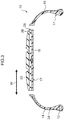
Fig. 5B is a cross-section illustrating a side portion of a tire that has been sliced by a slicer. -
Fig. 6 is a perspective view illustrating a state in which a tread portion of a tire is being compressed by metal rollers to separate a rubber layer. -
Fig. 7 is a perspective view illustrating a state in which a tire frame member is being crushed by metal rollers to separate a reinforcing member. - Explanation follows regarding an example of a tire dismantling method according to an exemplary embodiment of the present invention, with reference to
Fig. 1 to Fig. 7 . - In
Fig. 1 , a tire width direction running along a tire rotation axis is indicated by the letter W, a direction moving away from the tire rotation axis at right angles to the tire rotation axis is referred to as a tire radial direction and indicated by the letter R, and a plane passing through the center of the tire width direction W at right angles to the tire rotation axis is referred to as a tire equatorial plane and indicated by the letters CL. - As illustrated in
Fig. 1 , atire 10 of the present exemplary embodiment is a pneumatic tire employed with air filled inside, and includes atire frame member 17. Thetire frame member 17 includes a pair ofbead portions 12, a pair ofside portions 14 extending from therespective bead portions 12 toward a tire radial direction R outside, and acrown portion 16 that couples respective tire radial direction R outside ends of theside portions 14 together. - The
tire frame member 17 is formed of a pair of circular ring shaped tireframe half parts 17A, that each have the same shape as each other and are configured by molding asingle bead portion 12, asingle side portion 14, and a half-widthcrown half portion 16A together as an integral unit. A leadingend 16B of eachcrown half portion 16A is formed with a sloped face on the tire equatorial plane CL side, and the pair of leadingends 16B form a taper. - The pair of tire
frame half parts 17A abut each other at leadingends 16B of thecrown half portions 16A on the tire equatorial plane CL, and are bonded together using athermoplastic welding material 19 to form thetire frame member 17. - The
tire frame member 17 is formed of a thermoplastic resin. Thermoplastic resins are polymer compounds of materials that soften and flow with increased temperature, that adopt a relatively hard and strong state when cooled, and that do not have a rubber-like elasticity. - Examples of thermoplastic resins include polyolefin resins, polystyrene resins, polyamide resins, polyester resins, urethane resins, olefin resins, and vinyl chloride resins.
- A material having a deflection temperature under load (at 0.45 MPa during loading), as defined by ISO 75-2 or ASTM D648, of 78°C or greater, a tensile yield strength, as defined by JIS K7113, of 10 MPa or greater, a tensile elongation at break (JIS K7113), also as defined by JIS K7113, of 50% or greater, and a Vicat softening temperature, as defined by JIS K7206 (method A), of 130°C, for example, may be employed as the
thermoplastic welding material 19. Note that the same thermoplastic resin as that employed for thetire frame member 17 may be employed for thethermoplastic welding material 19. - Each tire
frame half part 17A formed using a thermoplastic resin may, for example, be molded by a method such as vacuum molding, pressure molding, injection molding, or melt casting, enabling the manufacturing process to be greatly simplified and enabling molding time to be reduced compared to cases in which the tireframe half part 17A is molded and vulcanized using rubber. - Note that the
tire frame member 17 may be configured by a single thermoplastic resin, or may employ thermoplastic resins having different characteristics in each location of the tire frame member 17 (such as theside portions 14, thecrown portion 16, and the bead portions 12), similarly to ordinary conventional pneumatic tires made of rubber, these locations being joined together. - As illustrated in
Fig. 2 , each of the pair ofbead portions 12 is in close contact with abead seat portion 21 and arim flange 22 of arim 20, so as to maintain the internal pressure of the tire filled with air. An annularshaped bead core 15 is embedded in eachbead portion 12 of thetire frame member 17. Thebead core 15 is formed of steel cord, similarly to in ordinary conventional pneumatic tires. - Note that the
bead cores 15 may be omitted, as long as the rigidity of thebead portions 12 is secured, and there are no issues with fitting to therim 20. Thebead cores 15 may be formed of metal cord other than steel cord, organic fiber cord, cord made of resin-covered organic fibers, or the like. Thebead cores 15 may alternatively be formed of a hard resin by injection molding or the like, rather than cord. - As illustrated in
Fig. 1 , a covering layer (rubber layer) 24 formed of rubber is formed from eachbead portion 12 to the tire width direction W outside of thecrown portion 16 on thetire frame member 17, and is vulcanization bonded to an outer face of thetire frame member 17. The same type of rubber as the rubber employed for bead portion outer faces of ordinary conventional pneumatic tires made of rubber is preferably employed as the rubber forming thecovering layer 24. - A reinforcing
layer 28, including cord (reinforcing member) 26 wound in a spiral shape, is laid up at the tire radial direction R outside of thecrown portion 16 of thetire frame member 17. The reinforcinglayer 28 corresponds to a belt disposed on an outer circumferential face of a carcass of a conventional pneumatic tires made of rubber. A material such as metal, with a higher rigidity than the thermoplastic resin forming thetire frame member 17, is employed as thecord 26, and steel cord made of twisted steel fibers is employed in the present exemplary embodiment. - The reinforcing
layer 28 may be formed of thecord 26 alone, or may be formed in sheet form in which thecord 26 is covered by a thermoplastic resin. In the present exemplary embodiment, the reinforcinglayer 28 is formed in sheet form in which thecord 26 is covered by the same type of thermoplastic resin as thetire frame member 17. The reinforcinglayer 28 is laid up by bonding or welding part thereof to thetire frame member 17 so that thetire frame member 17 and the reinforcinglayer 28 are integrated together. - A tread member (rubber layer) 30 is disposed at the tire radial direction outside of the
crown portion 16 of thetire frame member 17, and is vulcanization bonded to the outer face of thetire frame member 17. Thetread member 30 is disposed along thetire frame member 17, and configures a tire tread, this being a ground contact portion of thetire 10. Thetread member 30 is laminated onto thetire frame member 17, with the reinforcinglayer 28 interposed therebetween. - The
tread member 30 is formed of a rubber having a superior wear resistance to the thermoplastic resin forming thetire frame member 17. The same type of rubber as the rubber employed in conventional pneumatic tires made of rubber may be employed as the rubber employed in thetread member 30. - Explanation follows regarding a dismantling method and dismantling processes of the
tire 10 of the present exemplary embodiment. First, in a bead extraction process, thebead cores 15 embedded in thebead portions 12 of thetire frame member 17 are gripped and pulled out by a chuck using bead extraction equipment, not illustrated in the drawings. - Then, in a side cutting process, a circular disc cutter, disposed with its axis along the tire width direction W, of a tire cutting machine, not illustrated in the drawings, is moved in the tire radial direction R so as to approach and cut the
tire 10 along the tire radial direction R while being rotated along the tire circumferential direction. Specifically, as illustrated inFig. 3 , thetire frame member 17 is cut at two locations, so as to be separated into thecrown portion 16 and the pair ofside portions 14. Note that the cut locations are not limited to between thecrown portion 16 and theside portions 14, and thetire 10 may be cut along the tire radial direction R at three or more locations. - Next, in an opening-out process, the circular ring shaped
tire 10 is cut along the tire width direction W, such thattire 10 is made into a belt shape. Thetire 10 may be made into a belt shape by being cut at one location along the tire width direction W; however, thetire 10 may also be cut at plural locations to form plural tire pieces. Note that thetire 10 is cut at eight locations to form eight tire pieces in the present exemplary embodiment. - Explanation follows regarding a pressing process and a slicing process for a
tire piece 40 of thecrown portion 16 of thetire frame member 17 inFig. 4 , thetire piece 40 being one of the eight cut tire pieces. - As illustrated in
Fig. 4 , in the pressing process, thetire piece 40 that curves in the tire circumferential direction and tire width direction is clamped between a pair ofguide rollers 42 and pressed into a plate shape. Specifically, a spacing between the pair ofguide rollers 42 has the same dimension as, or a dimension that is slightly smaller than, the plate thickness of thetire piece 40, enabling thetire piece 40 to be pressed. Thetire piece 40 is clamped between theguide rollers 42, and theguide rollers 42 are rotated in the arrow A directions, such that thetire piece 40 is pressed and straightened into a flat plate shape. - Then, the
tire piece 40 that has been straightened into a flat plate shape is fed out from theguide rollers 42 in the arrow C direction, and sliced by aslicer 44 in the slicing process. Theslicer 44 includes a pair ofrotating drums 46, an endlessband knife blade 48 spanning between therotating drums 46, and a pair ofwhetstones 49 that sharpen theband knife blade 48. - The
band knife blade 48 spans between the rotation-drivenrotating drums 46, and rotates at high speed in the arrow B direction. Theband knife blade 48 is constantly sharpened by thewhetstones 49. Theband knife blade 48 is rotated in a direction orthogonal to the feed-out direction of thetire piece 40, and slices thetire piece 40 along an interface of thetread member 30 withtire frame member 17. - Specifically, as illustrated in
Fig. 5A , the fed-outtire piece 40 is sliced further toward the tire radial direction inside (the lower side inFig. 5A ) of thecrown portion 16 of thetire frame member 17 than the reinforcinglayer 28. Slicing further toward the lower side than the reinforcinglayer 28 enables thetire piece 40 to be separated and dismantled into atire piece 40A including materials such as rubber and steel, and thetire frame member 17 formed of a thermoplastic resin. - In order to prevent softening of the
tire frame member 17 formed of thermoplastic resin, the ambient temperature in the slicing process of thetire piece 40 is regulated to be at what is referred to as room temperature, this being from 10°C to 40°C. Note that, although the optimal ambient temperature is from 20°C to 30°C, softening of the thermoplastic resin can be sufficiently prevented even at from 0°C to 100°C. - Although the pressing process and slicing process of the
tire piece 40 of thecrown portion 16 of thetire frame member 17 have been explained above, a pressing process and a slicing process of atire piece 41 of theside portions 14 of thetire frame member 17 are similar processes to those of thetire piece 40. Note that, as illustrated inFig. 5B , since the reinforcinglayer 28 is not laid up on thetire piece 41, thetire piece 41 is sliced by theband knife blade 48 further toward the tire radial direction inside (the lower side inFig. 5B ) than an interface of thecovering layer 24 with theside portion 14 of thetire frame member 17. By slicing further toward the lower side than the interface, thetire frame member 17 formed of thermoplastic resin can be separated and dismantled from thetire piece 41 that includes rubber. - Note that various other dismantling methods were investigated before arriving at the dismantling method of thermoplastic resin with the above-described slicing process.
- First, a dismantling method was tried in which the
tire 10 was ground into a powder, then only the thermoplastic resin (tire frame member 17) was separated. Since the thermoplastic resin (tire frame member 17) and the rubber layer (tread member 30) are vulcanization bonded together, it was difficult to separate and dismantle the thermoplastic resin alone. - A dismantling method was also tried in which the thermoplastic resin (tire frame member 17) was sliced by a plane used for woodworking or a cutter used for meat or fish processing. The thermoplastic resin (tire frame member 17) came away from the rubber layer (tread member 30) partially and fragmented, such that the thermoplastic resin (tire frame member 17) could not be separated and dismantled from the rubber layer (tread member 30) in a state with its shape maintained.
- A dismantling method was also tried in which the thermoplastic resin (tire frame member 17) was sliced by an ultrasonic cutter used for plastic machining. The thermoplastic resin (tire frame member 17) softened or melted under the frictional vibration heat of the cutter, and the thermoplastic resin (tire frame member 17) could not be separated and dismantled from the rubber layer (tread member 30) in a state with its shape maintained.
- However, in the pressing method and the slicing method of the present exemplary embodiment, after the
curved tire piece 40 has been pressed by theguide rollers 42 and straightened into a flat plate shape, thetire piece 40 is sliced by theband knife blade 48 rotating at high speed, thereby enabling the thermoplastic resin (tire frame member 17) to be separated and dismantled from the rubber layer (tread member 30) in a state with its shape maintained. Since, in contrast to an ultrasonic cutter, the endlessband knife blade 48 does not generate frictional vibration heat, there is no concern of the thermoplastic resin (tire frame member 17) softening or melting. - After the
tire piece 40 has been separated further to the lower side than the reinforcinglayer 28 of thecrown portion 16 in the slicing process, thetread member 30 is separated from thetire piece 40A in a rubber layer separation process. Specifically, as illustrated inFig. 6 , thetire piece 40A formed of thetread member 30, the reinforcinglayer 28, and thetire frame member 17 is inserted between a pair ofmetal rollers 50. - The pair of
metal rollers 50 are rotated at the same rotation speed, and a spacing between themetal rollers 50 is set narrower than the plate thickness of thetire frame member 17. Thus, compression force or shear force is applied to thetire piece 40A that has been inserted between themetal rollers 50, due to themetal rollers 50 rotating. Since the rubber forming thetread member 30 has elasticity in comparison to the thermoplastic resin forming thetire frame member 17, a portion of thetread member 30 that is bonded to thetire frame member 17 is compressed under compression force or shear force and breaks, and thetire piece 40A is separated into thetread member 30 and atire piece 40B. Note that the spacing between themetal rollers 50 may be set wider than the plate thickness of thetire frame member 17, and narrower than the plate thickness of thetire piece 40A. - Note that the
tread member 30 and thetire frame member 17 of thetire piece 40A are difficult to separate from each other when the thermoplastic resin forming thetire frame member 17 is softened, and so the ambient temperature in the rubber layer separation process is regulated to be at what is referred to as room temperature, this being from 10°C to 40°C. - Next, the
cord 26 of the reinforcinglayer 28 is also separated from thetire piece 40B, from which thetread member 30 has already been separated, in a reinforcing member separation process. Specifically, as illustrated inFig. 7 , thetire piece 40B formed of the reinforcinglayer 28 and thetire frame member 17 is inserted between a pair ofmetal rollers 60. - The pair of
metal rollers 60 are rotated at the same rotation speed, and a spacing between themetal rollers 60 is set wider than the thickness (diameter) of thecord 26, and at from 2% to 20% of the plate thickness of thetire frame member 17. A metal with substantially the same rigidity as thecord 26, or with lower rigidity than thecord 26, and with higher rigidity than the thermoplastic resin forming thetire frame member 17, is employed for themetal rollers 60. - When the thermoplastic resin forming the
tire frame member 17 is softened, thecord 26 and thetire frame member 17 are difficult to separate from each other, and so the ambient temperature in the reinforcing member separation process is also regulated to be at room temperature, this being from 10°C to 40°C, and is preferably from 20°C to 30°C. - Since the spacing between the
metal rollers 60 is set so as to be much narrower than the plate thickness of thetire frame member 17, compression force is applied to theentire tire piece 40B when thetire piece 40B is inserted between therotating metal rollers 60. Since themetal rollers 60 have higher rigidity than the thermoplastic resin forming thetire frame member 17, thetire frame member 17 is crushed by the compression force. Since thecord 26 has substantially the same rigidity as, or higher rigidity than, themetal rollers 60, thecord 26 is separated from thetire frame member 17 without being crushed by themetal rollers 60. - In the dismantling method of the
tire 10 of the present exemplary embodiment, since the threedimensional tire 10 having a curved surface is cut and made into a plate shape, thetire 10 can be sliced along the interface between the laminatedtire frame member 17 and the tread member 30 (covering layer 24), and the thermoplastic resin forming thetire frame member 17 can be dismantled and recycled as a material in material recycling. - By crushing the
tire frame member 17 between themetal rollers 60 with the narrow spacing therebetween, thecord 26 laid up on thetire frame member 17 can be removed simply, and the material such as steel that forms thecord 26 can also be recycled as material. - Since the ambient temperature is set at room temperature in the slicing process, the rubber layer separation process, and the reinforcing member separation process, and since the
slicer 44 including the endlessband knife blade 48 that does not generate frictional vibration heat is employed in the slicing process, the dismantling processes can be efficiently performed without thetire frame member 17 softening. - In the above exemplary embodiment, the slicing process and so on are performed separately after the
tire frame member 17 has been separated into thecrown portion 16 and theside portions 14 in the side cutting process. However, the side cutting process may be omitted, and thetire 10 cut along the width direction into a belt shape to perform the dismantling processes without separating thecrown portion 16 and theside portions 14 from each other. - Although the
cord 26 is separated from thetire frame member 17 in the reinforcing member separation process, the reinforcing member is not limited to thecord 26. For example, thebead cores 15 may be separated from thetire frame member 17 as reinforcing members. It is sufficient that the reinforcing material, such as thecord 26, is a material that has a higher rigidity than thetire frame member 17, and there is no particular limitation regarding the substance. - In the reinforcing member separation process, the
tire piece 40B is crushed by themetal rollers 60; however, thetire piece 40B may be pressed and crushed by a press or the like. In the rubber layer separation process and the reinforcing member separation process, thesame metal rollers 60 may be employed to compress or to crush thetire pieces tread member 30 may be sliced by theslicer 44 in the rubber layer separation process without compressing and breaking thetread member 30, thereby separating thetread member 30 from thetire frame member 17. - The entire content of the disclosure of
Japanese Patent Application No. 2014-035585 filed February 26, 2014
Claims (6)
- A method for dismantling a tire, the tire including a tire frame member formed of a thermoplastic resin and a rubber layer that is vulcanization bonded to an outer face of the tire frame member, the method comprising:an opening-out process of cutting the tire along a width direction to make the tire into a belt shape; anda slicing process of slicing the belt shaped tire along an interface of the rubber layer with the tire frame member.
- The method for dismantling a tire of claim 1, further comprising a pressing process of pressing the tire into a plate shape after the opening-out process.
- The method for dismantling a tire of claim 1 or claim 2, further comprising:a bead extraction process of extracting a bead core from the tire frame member; anda side cutting process of cutting off a side portion of the tire frame member.
- The method for dismantling a tire of any one of claim 1 to claim 3, wherein:a reinforcing member is laid up at a tire radial direction outside of the tire frame member;the rubber layer is provided at the tire radial direction outside of the reinforcing member; andin the slicing process, the tire frame member is sliced further toward a tire radial direction inside than the reinforcing member.
- The method for dismantling a tire of any one of claim 1 to claim 4, wherein an ambient temperature in the slicing process is from 10°C to 40°C.
- The method for dismantling a tire of any one of claim 1 to claim 5, wherein, in the slicing process, the tire is sliced by a slicer including an endless band knife blade.
Applications Claiming Priority (2)
| Application Number | Priority Date | Filing Date | Title |
|---|---|---|---|
| JP2014035585A JP6347964B2 (en) | 2014-02-26 | 2014-02-26 | Tire separation method |
| PCT/JP2015/055021 WO2015129620A1 (en) | 2014-02-26 | 2015-02-23 | Method for separating tire |
Publications (3)
| Publication Number | Publication Date |
|---|---|
| EP3112113A1 true EP3112113A1 (en) | 2017-01-04 |
| EP3112113A4 EP3112113A4 (en) | 2017-02-22 |
| EP3112113B1 EP3112113B1 (en) | 2018-06-27 |
Family
ID=54008939
Family Applications (1)
| Application Number | Title | Priority Date | Filing Date |
|---|---|---|---|
| EP15756017.8A Active EP3112113B1 (en) | 2014-02-26 | 2015-02-23 | Method for taking apart tires |
Country Status (5)
| Country | Link |
|---|---|
| US (1) | US10040218B2 (en) |
| EP (1) | EP3112113B1 (en) |
| JP (1) | JP6347964B2 (en) |
| CN (1) | CN106029319B (en) |
| WO (1) | WO2015129620A1 (en) |
Cited By (2)
| Publication number | Priority date | Publication date | Assignee | Title |
|---|---|---|---|---|
| IT201800007739A1 (en) * | 2018-08-01 | 2020-02-01 | Alessandra Bonanno | PROCEDURE FOR PRODUCING FLOORING PANELS STARTING FROM DISCONTINUED TIRES AND THE RELATIVE FLOORING PANEL |
| WO2022260512A1 (en) | 2021-06-07 | 2022-12-15 | Innotech Europe B.V. | Extruder system and additive manufacturing printer, comprising such an extruder |
Families Citing this family (3)
| Publication number | Priority date | Publication date | Assignee | Title |
|---|---|---|---|---|
| JP6347964B2 (en) * | 2014-02-26 | 2018-06-27 | 株式会社ブリヂストン | Tire separation method |
| CN111231166A (en) * | 2020-01-13 | 2020-06-05 | 付桂侠 | Safe cutting equipment |
| DE102022212440A1 (en) * | 2022-11-22 | 2024-05-23 | Continental Reifen Deutschland Gmbh | Method for removing a tire layer |
Family Cites Families (30)
| Publication number | Priority date | Publication date | Assignee | Title |
|---|---|---|---|---|
| GB499567A (en) * | 1938-05-30 | 1939-01-25 | Arie Johan Stikkel | Improvements in and relating to means for slicing automobile tyres and the like |
| JPH068010B2 (en) * | 1986-06-09 | 1994-02-02 | 積水化成品工業株式会社 | Method for separating expanded polystyrene sheet |
| JPH03143701A (en) | 1989-10-27 | 1991-06-19 | Sumitomo Rubber Ind Ltd | Pneumatic tire |
| JPH04293605A (en) * | 1991-03-22 | 1992-10-19 | Bridgestone Corp | Cutting method and loading method for used tire |
| US5285707A (en) * | 1991-10-11 | 1994-02-15 | Allegheny Paper Shredders, Inc. | Tire cutting machine |
| US5768764A (en) * | 1996-04-22 | 1998-06-23 | Batt; Bernard E. | Steel bead wire extracting machine for tires |
| US5819631A (en) * | 1996-08-02 | 1998-10-13 | Foamex L.P. | Synthetic foam surface contouring machine |
| JPH10202659A (en) * | 1997-01-21 | 1998-08-04 | Yoshisuke Miyano | Processing method and processing apparatus for resin container |
| US6928911B1 (en) * | 1998-07-17 | 2005-08-16 | The Goodyear Tire & Rubber Company | Method and apparatus for cutting tire ply stock |
| FR2794396B1 (en) | 1999-06-04 | 2001-08-03 | Sanzio Agostinelli | MACHINE FOR PULLING UP THE TIRES INTEGRATED IN TIRES |
| FR2785220B1 (en) * | 1998-11-02 | 2001-01-12 | Soc D Const De Machines De Rec | PROCESS FOR THE TREATMENT AND RECYCLING OF TIRES, ESPECIALLY AND THE INSTALLATION FOR IMPLEMENTING THE PROCESS |
| FR2798089A1 (en) * | 1999-09-08 | 2001-03-09 | Loic Prioul | Recycling procedure for large tyres uses high-pressure water jets to cut off tyre walls before removing tread |
| JP2003534956A (en) * | 2000-10-06 | 2003-11-25 | ジョン ドボジー, | Method and apparatus for recovering elastomer material |
| JP2002370227A (en) * | 2001-06-15 | 2002-12-24 | National Institute Of Advanced Industrial & Technology | Metal wire removal method from tire by induction heating |
| WO2003035379A1 (en) * | 2001-10-25 | 2003-05-01 | Pirelli Pneumatici S.P.A. | Method and apparatus for cutting a ribbon of rubber-coated fabric |
| DE60317137T2 (en) * | 2002-06-28 | 2008-02-14 | Sumitomo Rubber Industries Ltd., Kobe | Method of making a studless tire with a tire tread |
| JP2004136423A (en) * | 2002-10-21 | 2004-05-13 | Yoshiaki Nitta | Waste tire fractionating method and its device |
| US20060052500A1 (en) * | 2004-09-03 | 2006-03-09 | Fu-Yuan Cheng | Rubber eraser and method of fabrication |
| US20060070504A1 (en) * | 2004-10-01 | 2006-04-06 | Downing Daniel R | Apparatus for cutting elastomeric materials |
| JP4004518B2 (en) * | 2005-10-04 | 2007-11-07 | 横浜ゴム株式会社 | Pneumatic tire using rubber laminate |
| US7975579B1 (en) * | 2007-04-24 | 2011-07-12 | Eagle International, Llc | System and method for cutting tires |
| US8465618B2 (en) * | 2007-10-22 | 2013-06-18 | Rubber Recovery Solutions Llc | Recovery of high value rubber from tires |
| RU2375178C1 (en) * | 2008-05-26 | 2009-12-10 | Государственное образовательное учреждение высшего профессионального образования "Ярославский государственный технический университет" | Method for cutting of composite products of circular shape |
| JP5081265B2 (en) * | 2010-03-09 | 2012-11-28 | 住友ゴム工業株式会社 | Manufacturing method of rubber member for tire and manufacturing apparatus used therefor |
| US8597449B2 (en) * | 2010-11-24 | 2013-12-03 | The Goodyear Tire & Rubber Company | Method for recovering uncured rubber and tire including reclaimed rubber |
| JP5836669B2 (en) * | 2011-07-04 | 2015-12-24 | 株式会社ブリヂストン | Tire processing method |
| FR2998217B1 (en) * | 2012-11-19 | 2015-01-09 | Michelin & Cie | MACHINE AND METHOD FOR CALIBRATION OF TIRES AT END OF LIFE |
| PL2803459T3 (en) * | 2013-05-13 | 2017-03-31 | Gomavial Solutions, S.L. | Device and method for removing a tread from a tire |
| JP6377366B2 (en) * | 2014-02-26 | 2018-08-22 | 株式会社ブリヂストン | Tire separation method |
| JP6347964B2 (en) * | 2014-02-26 | 2018-06-27 | 株式会社ブリヂストン | Tire separation method |
-
2014
- 2014-02-26 JP JP2014035585A patent/JP6347964B2/en not_active Expired - Fee Related
-
2015
- 2015-02-23 WO PCT/JP2015/055021 patent/WO2015129620A1/en not_active Ceased
- 2015-02-23 EP EP15756017.8A patent/EP3112113B1/en active Active
- 2015-02-23 CN CN201580010480.2A patent/CN106029319B/en not_active Expired - Fee Related
- 2015-02-23 US US15/120,741 patent/US10040218B2/en active Active
Cited By (3)
| Publication number | Priority date | Publication date | Assignee | Title |
|---|---|---|---|---|
| IT201800007739A1 (en) * | 2018-08-01 | 2020-02-01 | Alessandra Bonanno | PROCEDURE FOR PRODUCING FLOORING PANELS STARTING FROM DISCONTINUED TIRES AND THE RELATIVE FLOORING PANEL |
| EP3603830A1 (en) * | 2018-08-01 | 2020-02-05 | Alessandra Bonanno | A method for producing rubber flooring panels starting from out-of-use tires and corresponding flooring panel |
| WO2022260512A1 (en) | 2021-06-07 | 2022-12-15 | Innotech Europe B.V. | Extruder system and additive manufacturing printer, comprising such an extruder |
Also Published As
| Publication number | Publication date |
|---|---|
| JP6347964B2 (en) | 2018-06-27 |
| CN106029319B (en) | 2018-09-07 |
| EP3112113A4 (en) | 2017-02-22 |
| EP3112113B1 (en) | 2018-06-27 |
| US10040218B2 (en) | 2018-08-07 |
| CN106029319A (en) | 2016-10-12 |
| WO2015129620A1 (en) | 2015-09-03 |
| JP2015160336A (en) | 2015-09-07 |
| US20160368172A1 (en) | 2016-12-22 |
Similar Documents
| Publication | Publication Date | Title |
|---|---|---|
| EP3112113B1 (en) | Method for taking apart tires | |
| EP1262288B1 (en) | Method for cutting elastomeric materials | |
| EP3112112B1 (en) | Method for taking apart tires | |
| US8465618B2 (en) | Recovery of high value rubber from tires | |
| US11958260B2 (en) | Tire with variable shear element | |
| US11904561B2 (en) | Tire with shaped tread | |
| US6575064B2 (en) | Method and apparatus for cutting elastomeric materials | |
| WO2000023261A1 (en) | Method and apparatus for cutting elastomeric materials | |
| EP3086930A1 (en) | Precured tire tread with fabric reinforcing layer | |
| JPH1044720A (en) | Pneumatic tire | |
| WO2012023523A1 (en) | Method for processing tire and apparatus for processing tire | |
| WO2013049873A1 (en) | Tyre cutting and fragmenting device and method | |
| WO2014038619A1 (en) | Steel cord, and method for producing rubber product | |
| KR102647102B1 (en) | Apparatus for separating waste tire | |
| CN107405800B (en) | Tire mold molding elements, tire vulcanization molding molds, and tires | |
| JP5619528B2 (en) | tire | |
| RU2337002C1 (en) | Method of cutting of composite items of annular shape | |
| CA2332060A1 (en) | Method for producing fiber reinforced webbing material from recycled vehicle tires |
Legal Events
| Date | Code | Title | Description |
|---|---|---|---|
| PUAI | Public reference made under article 153(3) epc to a published international application that has entered the european phase |
Free format text: ORIGINAL CODE: 0009012 |
|
| STAA | Information on the status of an ep patent application or granted ep patent |
Free format text: STATUS: REQUEST FOR EXAMINATION WAS MADE |
|
| 17P | Request for examination filed |
Effective date: 20160830 |
|
| AK | Designated contracting states |
Kind code of ref document: A1 Designated state(s): AL AT BE BG CH CY CZ DE DK EE ES FI FR GB GR HR HU IE IS IT LI LT LU LV MC MK MT NL NO PL PT RO RS SE SI SK SM TR |
|
| AX | Request for extension of the european patent |
Extension state: BA ME |
|
| A4 | Supplementary search report drawn up and despatched |
Effective date: 20170123 |
|
| RIC1 | Information provided on ipc code assigned before grant |
Ipc: B60C 5/01 20060101ALI20170117BHEP Ipc: B60C 19/00 20060101ALI20170117BHEP Ipc: B29B 17/02 20060101AFI20170117BHEP |
|
| DAX | Request for extension of the european patent (deleted) | ||
| GRAP | Despatch of communication of intention to grant a patent |
Free format text: ORIGINAL CODE: EPIDOSNIGR1 |
|
| STAA | Information on the status of an ep patent application or granted ep patent |
Free format text: STATUS: GRANT OF PATENT IS INTENDED |
|
| INTG | Intention to grant announced |
Effective date: 20180112 |
|
| GRAS | Grant fee paid |
Free format text: ORIGINAL CODE: EPIDOSNIGR3 |
|
| GRAA | (expected) grant |
Free format text: ORIGINAL CODE: 0009210 |
|
| STAA | Information on the status of an ep patent application or granted ep patent |
Free format text: STATUS: THE PATENT HAS BEEN GRANTED |
|
| AK | Designated contracting states |
Kind code of ref document: B1 Designated state(s): AL AT BE BG CH CY CZ DE DK EE ES FI FR GB GR HR HU IE IS IT LI LT LU LV MC MK MT NL NO PL PT RO RS SE SI SK SM TR |
|
| REG | Reference to a national code |
Ref country code: GB Ref legal event code: FG4D |
|
| REG | Reference to a national code |
Ref country code: AT Ref legal event code: REF Ref document number: 1011907 Country of ref document: AT Kind code of ref document: T Effective date: 20180715 |
|
| REG | Reference to a national code |
Ref country code: IE Ref legal event code: FG4D |
|
| REG | Reference to a national code |
Ref country code: DE Ref legal event code: R096 Ref document number: 602015012800 Country of ref document: DE |
|
| REG | Reference to a national code |
Ref country code: DE Ref legal event code: R082 Ref document number: 602015012800 Country of ref document: DE Representative=s name: BARDEHLE PAGENBERG PARTNERSCHAFT MBB PATENTANW, DE |
|
| PG25 | Lapsed in a contracting state [announced via postgrant information from national office to epo] |
Ref country code: SE Free format text: LAPSE BECAUSE OF FAILURE TO SUBMIT A TRANSLATION OF THE DESCRIPTION OR TO PAY THE FEE WITHIN THE PRESCRIBED TIME-LIMIT Effective date: 20180627 Ref country code: LT Free format text: LAPSE BECAUSE OF FAILURE TO SUBMIT A TRANSLATION OF THE DESCRIPTION OR TO PAY THE FEE WITHIN THE PRESCRIBED TIME-LIMIT Effective date: 20180627 Ref country code: BG Free format text: LAPSE BECAUSE OF FAILURE TO SUBMIT A TRANSLATION OF THE DESCRIPTION OR TO PAY THE FEE WITHIN THE PRESCRIBED TIME-LIMIT Effective date: 20180927 Ref country code: FI Free format text: LAPSE BECAUSE OF FAILURE TO SUBMIT A TRANSLATION OF THE DESCRIPTION OR TO PAY THE FEE WITHIN THE PRESCRIBED TIME-LIMIT Effective date: 20180627 Ref country code: NO Free format text: LAPSE BECAUSE OF FAILURE TO SUBMIT A TRANSLATION OF THE DESCRIPTION OR TO PAY THE FEE WITHIN THE PRESCRIBED TIME-LIMIT Effective date: 20180927 |
|
| REG | Reference to a national code |
Ref country code: NL Ref legal event code: MP Effective date: 20180627 |
|
| REG | Reference to a national code |
Ref country code: LT Ref legal event code: MG4D |
|
| PG25 | Lapsed in a contracting state [announced via postgrant information from national office to epo] |
Ref country code: HR Free format text: LAPSE BECAUSE OF FAILURE TO SUBMIT A TRANSLATION OF THE DESCRIPTION OR TO PAY THE FEE WITHIN THE PRESCRIBED TIME-LIMIT Effective date: 20180627 Ref country code: GR Free format text: LAPSE BECAUSE OF FAILURE TO SUBMIT A TRANSLATION OF THE DESCRIPTION OR TO PAY THE FEE WITHIN THE PRESCRIBED TIME-LIMIT Effective date: 20180928 Ref country code: LV Free format text: LAPSE BECAUSE OF FAILURE TO SUBMIT A TRANSLATION OF THE DESCRIPTION OR TO PAY THE FEE WITHIN THE PRESCRIBED TIME-LIMIT Effective date: 20180627 Ref country code: RS Free format text: LAPSE BECAUSE OF FAILURE TO SUBMIT A TRANSLATION OF THE DESCRIPTION OR TO PAY THE FEE WITHIN THE PRESCRIBED TIME-LIMIT Effective date: 20180627 |
|
| REG | Reference to a national code |
Ref country code: AT Ref legal event code: MK05 Ref document number: 1011907 Country of ref document: AT Kind code of ref document: T Effective date: 20180627 |
|
| PG25 | Lapsed in a contracting state [announced via postgrant information from national office to epo] |
Ref country code: NL Free format text: LAPSE BECAUSE OF FAILURE TO SUBMIT A TRANSLATION OF THE DESCRIPTION OR TO PAY THE FEE WITHIN THE PRESCRIBED TIME-LIMIT Effective date: 20180627 |
|
| PG25 | Lapsed in a contracting state [announced via postgrant information from national office to epo] |
Ref country code: CZ Free format text: LAPSE BECAUSE OF FAILURE TO SUBMIT A TRANSLATION OF THE DESCRIPTION OR TO PAY THE FEE WITHIN THE PRESCRIBED TIME-LIMIT Effective date: 20180627 Ref country code: RO Free format text: LAPSE BECAUSE OF FAILURE TO SUBMIT A TRANSLATION OF THE DESCRIPTION OR TO PAY THE FEE WITHIN THE PRESCRIBED TIME-LIMIT Effective date: 20180627 Ref country code: PL Free format text: LAPSE BECAUSE OF FAILURE TO SUBMIT A TRANSLATION OF THE DESCRIPTION OR TO PAY THE FEE WITHIN THE PRESCRIBED TIME-LIMIT Effective date: 20180627 Ref country code: EE Free format text: LAPSE BECAUSE OF FAILURE TO SUBMIT A TRANSLATION OF THE DESCRIPTION OR TO PAY THE FEE WITHIN THE PRESCRIBED TIME-LIMIT Effective date: 20180627 Ref country code: SK Free format text: LAPSE BECAUSE OF FAILURE TO SUBMIT A TRANSLATION OF THE DESCRIPTION OR TO PAY THE FEE WITHIN THE PRESCRIBED TIME-LIMIT Effective date: 20180627 Ref country code: AT Free format text: LAPSE BECAUSE OF FAILURE TO SUBMIT A TRANSLATION OF THE DESCRIPTION OR TO PAY THE FEE WITHIN THE PRESCRIBED TIME-LIMIT Effective date: 20180627 Ref country code: IS Free format text: LAPSE BECAUSE OF FAILURE TO SUBMIT A TRANSLATION OF THE DESCRIPTION OR TO PAY THE FEE WITHIN THE PRESCRIBED TIME-LIMIT Effective date: 20181027 |
|
| PG25 | Lapsed in a contracting state [announced via postgrant information from national office to epo] |
Ref country code: ES Free format text: LAPSE BECAUSE OF FAILURE TO SUBMIT A TRANSLATION OF THE DESCRIPTION OR TO PAY THE FEE WITHIN THE PRESCRIBED TIME-LIMIT Effective date: 20180627 Ref country code: SM Free format text: LAPSE BECAUSE OF FAILURE TO SUBMIT A TRANSLATION OF THE DESCRIPTION OR TO PAY THE FEE WITHIN THE PRESCRIBED TIME-LIMIT Effective date: 20180627 |
|
| REG | Reference to a national code |
Ref country code: DE Ref legal event code: R097 Ref document number: 602015012800 Country of ref document: DE |
|
| PLBE | No opposition filed within time limit |
Free format text: ORIGINAL CODE: 0009261 |
|
| STAA | Information on the status of an ep patent application or granted ep patent |
Free format text: STATUS: NO OPPOSITION FILED WITHIN TIME LIMIT |
|
| PG25 | Lapsed in a contracting state [announced via postgrant information from national office to epo] |
Ref country code: DK Free format text: LAPSE BECAUSE OF FAILURE TO SUBMIT A TRANSLATION OF THE DESCRIPTION OR TO PAY THE FEE WITHIN THE PRESCRIBED TIME-LIMIT Effective date: 20180627 |
|
| 26N | No opposition filed |
Effective date: 20190328 |
|
| PG25 | Lapsed in a contracting state [announced via postgrant information from national office to epo] |
Ref country code: SI Free format text: LAPSE BECAUSE OF FAILURE TO SUBMIT A TRANSLATION OF THE DESCRIPTION OR TO PAY THE FEE WITHIN THE PRESCRIBED TIME-LIMIT Effective date: 20180627 |
|
| REG | Reference to a national code |
Ref country code: CH Ref legal event code: PL |
|
| GBPC | Gb: european patent ceased through non-payment of renewal fee |
Effective date: 20190223 |
|
| PG25 | Lapsed in a contracting state [announced via postgrant information from national office to epo] |
Ref country code: MC Free format text: LAPSE BECAUSE OF FAILURE TO SUBMIT A TRANSLATION OF THE DESCRIPTION OR TO PAY THE FEE WITHIN THE PRESCRIBED TIME-LIMIT Effective date: 20180627 Ref country code: LU Free format text: LAPSE BECAUSE OF NON-PAYMENT OF DUE FEES Effective date: 20190223 |
|
| REG | Reference to a national code |
Ref country code: BE Ref legal event code: MM Effective date: 20190228 |
|
| REG | Reference to a national code |
Ref country code: IE Ref legal event code: MM4A |
|
| PG25 | Lapsed in a contracting state [announced via postgrant information from national office to epo] |
Ref country code: AL Free format text: LAPSE BECAUSE OF FAILURE TO SUBMIT A TRANSLATION OF THE DESCRIPTION OR TO PAY THE FEE WITHIN THE PRESCRIBED TIME-LIMIT Effective date: 20180627 |
|
| PG25 | Lapsed in a contracting state [announced via postgrant information from national office to epo] |
Ref country code: CH Free format text: LAPSE BECAUSE OF NON-PAYMENT OF DUE FEES Effective date: 20190228 Ref country code: LI Free format text: LAPSE BECAUSE OF NON-PAYMENT OF DUE FEES Effective date: 20190228 |
|
| PG25 | Lapsed in a contracting state [announced via postgrant information from national office to epo] |
Ref country code: GB Free format text: LAPSE BECAUSE OF NON-PAYMENT OF DUE FEES Effective date: 20190223 Ref country code: IE Free format text: LAPSE BECAUSE OF NON-PAYMENT OF DUE FEES Effective date: 20190223 |
|
| PG25 | Lapsed in a contracting state [announced via postgrant information from national office to epo] |
Ref country code: BE Free format text: LAPSE BECAUSE OF NON-PAYMENT OF DUE FEES Effective date: 20190228 |
|
| PG25 | Lapsed in a contracting state [announced via postgrant information from national office to epo] |
Ref country code: TR Free format text: LAPSE BECAUSE OF FAILURE TO SUBMIT A TRANSLATION OF THE DESCRIPTION OR TO PAY THE FEE WITHIN THE PRESCRIBED TIME-LIMIT Effective date: 20180627 |
|
| PG25 | Lapsed in a contracting state [announced via postgrant information from national office to epo] |
Ref country code: PT Free format text: LAPSE BECAUSE OF FAILURE TO SUBMIT A TRANSLATION OF THE DESCRIPTION OR TO PAY THE FEE WITHIN THE PRESCRIBED TIME-LIMIT Effective date: 20181029 Ref country code: MT Free format text: LAPSE BECAUSE OF NON-PAYMENT OF DUE FEES Effective date: 20190223 |
|
| PG25 | Lapsed in a contracting state [announced via postgrant information from national office to epo] |
Ref country code: CY Free format text: LAPSE BECAUSE OF FAILURE TO SUBMIT A TRANSLATION OF THE DESCRIPTION OR TO PAY THE FEE WITHIN THE PRESCRIBED TIME-LIMIT Effective date: 20180627 |
|
| PG25 | Lapsed in a contracting state [announced via postgrant information from national office to epo] |
Ref country code: HU Free format text: LAPSE BECAUSE OF FAILURE TO SUBMIT A TRANSLATION OF THE DESCRIPTION OR TO PAY THE FEE WITHIN THE PRESCRIBED TIME-LIMIT; INVALID AB INITIO Effective date: 20150223 |
|
| PGFP | Annual fee paid to national office [announced via postgrant information from national office to epo] |
Ref country code: IT Payment date: 20220218 Year of fee payment: 8 |
|
| PG25 | Lapsed in a contracting state [announced via postgrant information from national office to epo] |
Ref country code: MK Free format text: LAPSE BECAUSE OF FAILURE TO SUBMIT A TRANSLATION OF THE DESCRIPTION OR TO PAY THE FEE WITHIN THE PRESCRIBED TIME-LIMIT Effective date: 20180627 |
|
| PGFP | Annual fee paid to national office [announced via postgrant information from national office to epo] |
Ref country code: DE Payment date: 20230216 Year of fee payment: 9 |
|
| P01 | Opt-out of the competence of the unified patent court (upc) registered |
Effective date: 20230531 |
|
| PG25 | Lapsed in a contracting state [announced via postgrant information from national office to epo] |
Ref country code: IT Free format text: LAPSE BECAUSE OF NON-PAYMENT OF DUE FEES Effective date: 20230223 |
|
| REG | Reference to a national code |
Ref country code: DE Ref legal event code: R119 Ref document number: 602015012800 Country of ref document: DE |
|
| PG25 | Lapsed in a contracting state [announced via postgrant information from national office to epo] |
Ref country code: DE Free format text: LAPSE BECAUSE OF NON-PAYMENT OF DUE FEES Effective date: 20240903 |
|
| PG25 | Lapsed in a contracting state [announced via postgrant information from national office to epo] |
Ref country code: DE Free format text: LAPSE BECAUSE OF NON-PAYMENT OF DUE FEES Effective date: 20240903 |
|
| PGFP | Annual fee paid to national office [announced via postgrant information from national office to epo] |
Ref country code: FR Payment date: 20250221 Year of fee payment: 11 |