EP3112093A1 - Industrial robot - Google Patents
Industrial robot Download PDFInfo
- Publication number
- EP3112093A1 EP3112093A1 EP15003182.1A EP15003182A EP3112093A1 EP 3112093 A1 EP3112093 A1 EP 3112093A1 EP 15003182 A EP15003182 A EP 15003182A EP 3112093 A1 EP3112093 A1 EP 3112093A1
- Authority
- EP
- European Patent Office
- Prior art keywords
- ball
- arm portion
- internal passages
- arm
- head part
- Prior art date
- Legal status (The legal status is an assumption and is not a legal conclusion. Google has not performed a legal analysis and makes no representation as to the accuracy of the status listed.)
- Withdrawn
Links
Images







Classifications
-
- B—PERFORMING OPERATIONS; TRANSPORTING
- B25—HAND TOOLS; PORTABLE POWER-DRIVEN TOOLS; MANIPULATORS
- B25J—MANIPULATORS; CHAMBERS PROVIDED WITH MANIPULATION DEVICES
- B25J9/00—Program-controlled manipulators
- B25J9/003—Program-controlled manipulators having parallel kinematics
- B25J9/0045—Program-controlled manipulators having parallel kinematics with kinematics chains having a rotary joint at the base
- B25J9/0051—Program-controlled manipulators having parallel kinematics with kinematics chains having a rotary joint at the base with kinematics chains of the type rotary-universal-universal or rotary-spherical-spherical, e.g. Delta type manipulators
-
- B—PERFORMING OPERATIONS; TRANSPORTING
- B25—HAND TOOLS; PORTABLE POWER-DRIVEN TOOLS; MANIPULATORS
- B25J—MANIPULATORS; CHAMBERS PROVIDED WITH MANIPULATION DEVICES
- B25J13/00—Controls for manipulators
- B25J13/08—Controls for manipulators by means of sensing devices, e.g. viewing or touching devices
-
- B—PERFORMING OPERATIONS; TRANSPORTING
- B25—HAND TOOLS; PORTABLE POWER-DRIVEN TOOLS; MANIPULATORS
- B25J—MANIPULATORS; CHAMBERS PROVIDED WITH MANIPULATION DEVICES
- B25J17/00—Joints
- B25J17/02—Wrist joints
- B25J17/0258—Two-dimensional joints
- B25J17/0275—Universal joints, e.g. Hooke, Cardan, ball joints
-
- B—PERFORMING OPERATIONS; TRANSPORTING
- B25—HAND TOOLS; PORTABLE POWER-DRIVEN TOOLS; MANIPULATORS
- B25J—MANIPULATORS; CHAMBERS PROVIDED WITH MANIPULATION DEVICES
- B25J19/00—Accessories fitted to manipulators, e.g. for monitoring, for viewing; Safety devices combined with or specially adapted for use in connection with manipulators
- B25J19/06—Safety devices
- B25J19/063—Safety devices working only upon contact with an outside object
Definitions
- the present invention relates to an industrial robot including a parallel link mechanism.
- robot including a parallel link mechanism (hereinafter, referred to as "robot") such as one described in Japanese Patent Publication No. 4850863 (hereinafter, referred to as "Patent Document 1").
- This robot includes a base part serving as a support base, motors mounted on the base part, three arms to be respectively driven by the motors, and a head part connected to respective leading ends of the arms.
- Each of the arms includes a first arm portion connected to the motor and a second arm portion connecting the first arm portion and the head part. The position and the orientation of the head part are changed by driving the first arm portions by the motors.
- Each of the second arm portions includes a pair of rods, and is connected to a first arm portion and the head part via ball joints.
- each of the pair of rods is provided with cup-shaped sockets at its opposite ends.
- ball studs each have ball heads on the opposite ends thereof.
- One ball stud which constitutes ball joints in cooperation with the sockets at one respective ends of the pair of rods is secured to the first arm portion.
- the other ball stud which constitutes ball joints in cooperation with the sockets at the other respective ends of the pair of rods is secured to the head part.
- the sockets on the opposite ends of the rods respectively hold the ball heads of the ball studs and connecting members such as tension spring are provided between the rods to thereby connect the second arm portion to the first arm portion at one end, and to the head part at the other end.
- a rapid motion of a second arm portion due to a sudden acceleration or the like or a collision of a second arm portion against an obstacle may cause the rods to be accidentally separated largely from each other, which results in disengagement of the second arm portion from the corresponding first arm portion or the head part in the worst case.
- Such trouble is liable to occur particularly in the case that the robot is driven for a long period of time until a ball head of ball stud or a socket is worn out.
- the robot of the Patent Document 1 includes a circuit for detecting disengagement of a second arm portion.
- each of the pair of rods constituting a second arm portion includes a wire connecting the sockets secured at its opposite ends.
- each end of the pair of rods is provided with a conductive member electrically connecting the socket and the ball head of the ball stud.
- an electrical closed circuit detection circuit
- the present invention aims to detect a connection failure of an arm with a safer configuration.
- An industrial robot comprises: a base part; a plurality of motors mounted on the base part; a head part for holding an end effector; a plurality of arms provided for the plurality of motors, respectively, each arm including a first arm portion connected to the motor, a second arm portion connecting the first arm portion and the head part, a first ball joint pivotally connecting the first arm portion and the second arm portion, and a second ball joint pivotally connecting the second arm portion and the head part; and a detector for detecting a connection failure of a second arm portion, characterized in that: each of the first ball joints and the second ball joints includes a ball stud having a ball head, and a socket holding the ball head, each ball stud of at least either the first ball joints or the second ball joints includes an internal passage having an opening on an outside surface of the ball head, and the detector includes a pressurizing device for generating a specific pressure in the internal passages by supplying air into the internal passages or sucking air from the internal passages, and a
- FIGS. 1 and 2 are perspective views of an industrial robot 1 according to the present invention. As shown in these figures, the industrial robot 1 is of a parallel link type.
- the industrial robot 1 (hereinafter, simply referred to as “robot 1”) includes a base part 2 serving as a support base to be secured to a ceiling or a frame member, a head part 4 disposed below the base part 2, and three arms 6 connected to the head part 4 and configured to be respectively driven by arm driving motors 3 mounted on the base part 2.
- the robot 1 is so configured that the position and the orientation of the head part 4 is changed by driving the arms 6 independently and in combination.
- Three motor supporters 2a are provided on the base part 2 at regular intervals (at intervals of 120 degrees) around a vertical axis passing the center of the base part 2.
- the motor supporters 2a respectively fixedly support the arm driving motors 3.
- Each of the arm driving motors 3 is secured to the corresponding motor supporter 2a in a horizontal position with an output shaft extending in a horizontal direction.
- the arms 6 are respectively connected to the output shafts of the arm driving motors 3.
- Each of the arms 6 includes a first arm portion 10 connected to the output shaft of the arm driving motor 3, a second arm portion 12 connecting the first arm portion 10 and the head part 4, a first ball joint 14a pivotally connecting the first arm portion 10 and the second arm portion 12, and a second ball joint pivotally connecting the second arm portion 12 and the head part 4.
- the arm portion 10 is in the form of an arch slightly tapering from a base end to a leading end in side view, the base end being secured to the output shaft of the arm driving motor 3.
- the first arm portion 10 is in the form of a flat plate which is thin in the axial direction of the output shaft.
- the first arm portion 10 may be configured in the form of a box which is thick in the axial direction in order to enhance the strength.
- the second arm portion 12 includes a pair of cylindrical rods 13 made of a light material such as carbon fiber.
- the pair of rods 13 of the second arm portion 12 are connected to the first arm portion 10 via the first ball joint 14a and to the head part 4 via the second ball joint 4b. Consequently, the second arm portion 12 is pivotally connected to the first arm portion 10 and the head part 4.
- the configurations of the first ball joint 14a and the second ball joint 14b will be described in detail later.
- the head part 4 includes a bracket 30 connected with each of the arms 6, a nozzle driving motor 34 secured on the bracket 30, and a tool holder 32 rotatably supported on a central portion of the bracket 30 via a bearing or the like and configured to be driven by the nozzle driving motor 34.
- the tool holder 32 detachably holds an end effector.
- various types of nozzles for sucking articles are detachably mounted as an end effector.
- the first ball joint 14a includes a ball stud 20 secured to the first arm portion 10, and a pair of sockets 26 respectively secured to the pair of rods 13 and holding ball heads 22 of the ball stud 20.
- the ball stud 20 is in the form of a shaft and has the ball heads 22 at its opposite ends.
- the ball stud 20 is secured to and passes through a leading end of the first arm portion 10 in the thickness direction of the first arm portion 10.
- each of the pair of sockets 26 includes a socket body portion 27 secured to the corresponding rod 13, and a receiving portion 28 embedded in the socket body portion 27 and receiving the corresponding ball head 22.
- the sockets 26 are respectively secured to upper ends of the rods 13 and face each other, i.e. with the respective receiving portions 28 facing each other, and respectively hold the ball heads 22 via the receiving portions 28.
- the second ball joint 14b basically has a similar configuration to the first ball joint 14b and includes, as shown in FIGS. 7 to 9 , a ball stud 20 provided with the head part 4, and a pair of sockets 26 respectively secured to lower ends of the pair of rods 13 and holding ball heads 22 of the ball stud 20. It should be noted that elements of the second ball joint 14a that are identical to those of the first ball joint 14a are denoted by the same reference numerals as those of the first ball joint 14a and detailed description thereof will be omitted.
- the ball stud 20 of the second ball joint 14b is integrally provided in the bracket 30 of the head part 4. Specifically, as shown in FIG. 9 , a portion of the ball stud 20 of the second ball joint 14b other than the ball heads 22 are molded integrally with the bracket 30 from the same material as the bracket 30. Subsequently, the ball heads 22 are assembled to the bracket 30. Consequently, the ball studs 20 of the three second ball joints 14b connecting the second arm portions 12 are provided integrally in the bracket 30.
- each of the receiving portions 28 of the sockets 26 are relatively shallow with respect to the ball heads 22.
- each of the receiving portions 28 is formed with a contacting surface having an area covering a half of the outside surface of the ball head 22. This is to secure a range of pivot of the second arm portions 12 with respect to the corresponding first arm portions 10 and the head part 4 as widely as possible, and to allow attachment and detachment of the sockets 26 to and from the ball studs 20, i.e. attachment and detachment of the second arm portions 12 to and from the first arm portions 10 and the head part 4.
- a socket 26 may easily disengage from the corresponding ball stud 20, that is, a second arm portion 12 may easily disengage from the corresponding first arm portion 10 or the head part 4.
- a connecting member 16 is mounted to and extends across the socket body portions 27 of the opposite sockets 26 of each first ball joint 14a.
- each connecting member 16 is so configured to pull the pair of rods 30 toward each other owing to a resilient force of a spring. This allows the ball heads 22 to be kept held by the sockets 26, i.e. allows the first arm portion 10 and the second arm portion 12 to be kept connected with each other.
- the robot 1 includes the following configuration for detecting disengagement of any of the second arm portions 12 in order to stop immediately when the disengagement is detected.
- each ball stud 20 of the first ball joints 14a is formed with an internal passage 23 extending axially and having openings on respective outside surfaces of the opposite ball heads 22.
- the internal passage 23 is supplied with air at a specific pressure via a port section 20a (see FIG. 6 ) provided between the opposite ball heads 22.
- each of the second ball joints 14b in which the ball stud 20 is formed with an internal passage 23 extending axially and having openings on respective outside surfaces of the opposite ball heads 22, as shown in FIGS. 8 and 9 .
- the three internal passages 23 of the ball studs 20 of the second ball joints 14b communicate with each other via bridge tubes (corresponding to a communication passage of the present invention) 38 provided in the bracket 30.
- the bridge tubes 38 are provided between a specific ball stud 20 and each of the ball studs 20 disposed on both sides of the specific ball stud.
- the three internal passages 23 of the three ball studs 20 communicate with each other via the bridge tubes 38.
- the three internal passages 23 constitute a single passage. Consequently, air is supplied into the internal passages 23 of the ball studs 20 at the specific pressure via the port section 20a provided in the specific ball stud 20.
- Tubes for supplying air into the internal passages 23 of the ball studs 20 are arranged as follows. As shown in FIGS. 1 , 2 , 10 , and 11 , the base part 2 is equipped with an air distributor 40.
- the air distributor 40 includes an input port having therein a flow regulating valve, and three output ports.
- the input port is connected with an unillustrated compressor by a first air tube P1
- the output ports are respectively connected with the port sections 20a of the ball studs 20 of the three first ball joints 14a by second air tubes P2a to P2c.
- Each of the second air tubes P2a to P2c is arranged along a side surface of each first arm portion 10 from the base part 2.
- the port section 20a of the ball stud 20 of one of the three first ball joints 14a has two branch ports as shown in FIGS. 2 and 6 , and is connected with the port 20a of the specific ball stud 20 of the second ball joint 14b by a third air tube P3.
- the third air tube P3 is arranged along a rod 13 and secured to the rod 13 by a securing member such as tying band 42, as shown in FIGS. 1 , 6 and 7 .
- the air distributor 40 includes a pressure sensor 40a for detecting a pressure in the internal passages 23 of the ball joints 14a and 14b. Detection information obtained by the pressure sensor 40a is input into a controller 50 which controls the entirety of the robot 1. To be precise, the pressure sensor 40a detects a pressure in the first air tube P1 (input port). The distance between the pressure sensor 40a and the internal passages 23 is short and, therefore, the pressure in the first air tube P1 (input port) is substantially equal to the pressure in the internal passages 23. Therefore, the pressure sensor 40a is provided in the first air tube P1 (input port) in this embodiment.
- the reference signs L2a and L2b denote wires for controlling the nozzle driving motor 34.
- these wires L2a and L2b respectively pass through the pair of rods 13 constituting a second arm portion 12 with respective one ends extending out of the rods 13 and connected to a connecting device 44 secured on a specific first arm portion 10 by a connector and the respective other ends extending out of the rods 13 and connected to the nozzle driving motor 34 by a connector.
- the connecting device 44 is connected to the controller 50 via a wire L1.
- the controller 50 is based on a known microcomputer, and includes a central processing unit (CPU) for executing a program, a memory including, for example, RAM and ROM for storing programs and data, and an input/output (I/O) bus for allowing input and output of an electrical signal.
- CPU central processing unit
- memory including, for example, RAM and ROM for storing programs and data
- I/O input/output
- the controller 50 determines, based on detection information (detected pressure value) input from the pressure sensor 40a, whether any of the second arm portions 12 is disengaged from the corresponding first arm portion 10 or the head part 4, and stops the robot 1 when the disengagement is determined.
- the controller 50 determines that any of the second arm portions 12 of the three arms 6 is disengaged when the pressure value detected by the pressure sensor 40a continues to be less than a predetermined threshold value P, i.e. less than the pressure (the specific pressure) of air supplied into the internal passages 23 by a predetermined value (corresponding to a first change amount of the present invention) or more, for a predetermined set time period T1 (corresponding to a first set time period of the present invention) or more as shown in FIG. 12A .
- the controller 50 causes the robot 1 to immediately stop the operation, and activates an alarming device 52 (see FIG. 1 ) connected with the controller 50 to inform an operator of the disengagement.
- the robot 1 supplies air into the internal passages 23 respectively formed in the ball studs 20 of the ball joints 14a and 14b at a specific pressure and detects disengagement of any of the second arm portions 12 based on a pressure change in the internal passages 23.
- the above-described robot 1 can detect disengagement of a second arm portion 12 without applying an electric current to the ball joints. Therefore, unlike the conventional industrial robots of this type which detect disengagement of an arm based on electrical conduction between a ball stud and a socket, there is no likelihood of causing an electric shock at the time of maintenance. Consequently, it is possible to detect disengagement of any of the second arm portions 12 with a safer configuration.
- each of the second arm portions 12 includes a pair of rods 13, and the opposite ball heads 22 of each ball stud 20 are held by the sockets 26 secured to the rods 13, whereby the second arm portions 12 are connected with the corresponding first arm portions 10 and the head part 4.
- each of the internal passages 23 extends in the axial direction of the ball stud 20 and has openings on the respective outside surfaces of the opposite ball heads 22. Therefore, even when one of the pair of rods 13 is disengaged, the pressure sensor 40a detects a lower pressure value.
- the above-described robot 1 is advantageous in that it is possible to successfully detect, not only complete disengagement of a second arm portion 12 from the corresponding first arm portion 10 or the head part 4, but also disengagement of a rod 13 from the corresponding first arm portion 10 or the head part 4.
- the internal passages 23 of the ball studs 20 of the second ball joints 14b communicate with each other in series via the bridge tubes 38. This makes it possible to supply air into a specific (one) ball stud 20 through the third air tube P3 to thereby supply the air into all of the internal passages 23. Therefore, the above-described robot 1 is advantageous in that it is possible to simplify the layout of tubes around the head part 4 and prevent the tubes for air supply from obstructing the operation of the arms 6 or an end effector. In addition, the robot 1 can be assembled more easily.
- the above-described robot 1 exemplifies a preferred embodiment of an industrial robot according to the present invention, and the specific configuration thereof may be appropriately changed without departing from the scope of the present invention.
- the controller 50 determines, based on a pressure value detected by the pressure sensor 40a, whether any of the second arm portions 12 is disengaged, and stops the robot 1 when the disengagement is determined.
- the controller 50 may also be configured to determine whether any of the second arm portions 12 is likely to disengage, and stop the robot 1 when the likelihood of disengagement is determined.
- the controller 50 may be appreciated to count sudden reductions in detected pressure value in which the detected pressure value becomes less than the threshold value P only for a small time period shorter than the above-mentioned set time period T1, i.e.
- controller 50 has been described as determining disengagement and a likelihood of disengagement of any of the second arm portions 12. However, the controller 50 may be configured to only determine a likelihood of disengagement of any of the second arm portions 12.
- each ball stud 20 of second ball joints 14b is formed with an independent internal passage 23, and ball studs (internal passages 23) of first and second ball joints 14a, 14b of each arm 6 are connected in series by an air tube provided with a pressure sensor 40a.
- This configuration makes it possible to detect disengagement of a second arm portion 12 for each arm 6 based on a pressure value detected by a respective air distributor 40. Therefore, it is possible to specify an arm 6 having a disengaged second arm portion 12.
- the third air tube P3 is arranged along the outer surface of a rod 13 and secured to the rod 13 by the tying band 42.
- the third tube P3 may be arranged inside the rod 13, similarly to the wires L2a and L2b used for controlling the nozzle driving motor 34.
- the robot 1 of the above-described embodiment air is supplied into the internal passages 23 of the ball studs 20.
- the robot 1 may be configured such that air is sucked from the internal passages 23.
- a specific negative pressure may be generated in the internal passages 23 instead of supplying a specific positive pressure into the internal passages 23, to determine that any of the second arm portions 12 is disengaged when the pressure value detected by the pressure sensor 40a continues to be greater than a predetermined threshold value for a predetermined set time period or more.
- a likelihood of disengagement of any of the second arm portions 12 may be determined based on the number of times that the pressure value detected by the pressure sensor 40a suddenly exceeds a threshold value.
- Such configuration also makes it possible to provide advantageous effects similar to those of the above-described embodiment.
- An industrial robot comprises: a base part; a plurality of motors mounted on the base part; a head part for holding an end effector; a plurality of arms provided for the plurality of motors, respectively, each arm including a first arm portion connected to the motor, a second arm portion connecting the first arm portion and the head part, a first ball joint pivotally connecting the first arm portion and the second arm portion, and a second ball joint pivotally connecting the second arm portion and the head part; and a detector for detecting a connection failure of a second arm portion, characterized in that: each of the first ball joints and the second ball joints includes a ball stud having a ball head, and a socket holding the ball head, each ball stud of at least either the first ball joints or the second ball joints includes an internal passage having an opening on an outside surface of the ball head, and the detector includes a pressurizing device for generating a specific pressure in the internal passages by supplying air into the internal passages or sucking air from the internal passages, and a determination device for detecting a
- the determination device detects the above-mentioned connection failure of second arm portion based on such pressure change in the internal passages. This configuration makes it possible to detect a connection failure of a second arm portion without applying an electric current to the ball joints. Therefore, a connection failure of a second arm portion can be detected with a safer configuration.
- each of the second arm portions includes a pair of a first rod and a second rod extending in parallel to each other
- each of the first ball joints includes a socket secured at one end of the first rod and a socket secured at one end of the second rod, the both sockets facing each other, and a ball stud connected with a first arm portion and having ball heads facing in opposite directions, the ball heads being held by the sockets to thereby connect the first arm portion with the second arm portion
- each of the second ball joints includes a socket secured at the other end of the first rod and a socket secured at the other end of the second rod, the both sockets facing each other, and a ball stud connected with the head part and having ball heads facing in the opposite directions, the ball heads being held by the sockets to thereby connect the second arm portion with the head part, at least one of the first and second ball joints having an internal passage extending along an arrangement direction of the opposite ball heads and having openings on respective outside surfaces of the opposite ball heads.
- This configuration makes it possible to successfully detect such a connection failure that one of the pair of rods constituting a second arm portion is disengaged or is likely to disengage from the corresponding first arm portion (or the head part).
- the head part includes a communication passage connecting the respective internal passages of the ball studs of the second ball joints connecting the second arm portions, and that the pressurizing device supplies a specific pressure in the internal passage of a specific ball stud.
- This configuration makes it possible to simplify the layout of tubes for generating the specific pressure in the internal passages of the second ball joints.
- the pressurizing device includes a first tube communicating with one pressure supply source, a plurality of second tubes branching from the first tube and respectively connecting with the internal passages of the ball studs of the first ball joints, and a third tube branching from one of the second tubes and connecting with the internal passage of the specific ball stud.
- This configuration makes it possible to simply generate the specific pressure in the internal passages of the ball studs of the first ball joints and the second ball joints.
- only the single third tube is used for supplying the specific pressure to the second ball joints, which makes it possible to arrange (assemble) the tubes in an improved way and reduce influence on the operation of the arms.
- the determination device determines a disengaged state of a second arm portion as the connection failure of the second arm portion, the disengaged state of the second arm portion being determined when the pressure in the internal passages is detected to continue to deviate from the specific pressure by a predetermined first change amount or more for a predetermined first set time period or more.
- This configuration makes it possible to successfully detect disengagement of a second arm portion.
- the determination device determines a likelihood of disengagement of a second arm portion as the connection failure of the second arm portion, the likelihood of disengagement of the second arm portion being determined when the pressure in the internal passages is detected to instantaneously deviate from the specific pressure by a predetermined second change amount a predetermined number of times or more within a predetermined second set time period.
- This configuration makes it possible to successfully detect a state that a second arm portion is likely to disengage due to wear of a ball head or a socket of a ball stud, i.e. likelihood of disengagement of a second arm portion.
Landscapes
- Engineering & Computer Science (AREA)
- Robotics (AREA)
- Mechanical Engineering (AREA)
- Human Computer Interaction (AREA)
- Manipulator (AREA)
Abstract
Description
- The present invention relates to an industrial robot including a parallel link mechanism.
- Conventionally, there are known industrial robots including a parallel link mechanism (hereinafter, referred to as "robot") such as one described in
Japanese Patent Publication No. 4850863 Patent Document 1"). - This robot includes a base part serving as a support base, motors mounted on the base part, three arms to be respectively driven by the motors, and a head part connected to respective leading ends of the arms. Each of the arms includes a first arm portion connected to the motor and a second arm portion connecting the first arm portion and the head part. The position and the orientation of the head part are changed by driving the first arm portions by the motors.
- Each of the second arm portions includes a pair of rods, and is connected to a first arm portion and the head part via ball joints. Specifically, each of the pair of rods is provided with cup-shaped sockets at its opposite ends. On the other hand, ball studs each have ball heads on the opposite ends thereof. One ball stud which constitutes ball joints in cooperation with the sockets at one respective ends of the pair of rods is secured to the first arm portion. The other ball stud which constitutes ball joints in cooperation with the sockets at the other respective ends of the pair of rods is secured to the head part. The sockets on the opposite ends of the rods respectively hold the ball heads of the ball studs and connecting members such as tension spring are provided between the rods to thereby connect the second arm portion to the first arm portion at one end, and to the head part at the other end.
- In a robot of this type, a rapid motion of a second arm portion due to a sudden acceleration or the like or a collision of a second arm portion against an obstacle may cause the rods to be accidentally separated largely from each other, which results in disengagement of the second arm portion from the corresponding first arm portion or the head part in the worst case. Such trouble is liable to occur particularly in the case that the robot is driven for a long period of time until a ball head of ball stud or a socket is worn out.
- Accordingly, the robot of the
Patent Document 1 includes a circuit for detecting disengagement of a second arm portion. Specifically, each of the pair of rods constituting a second arm portion includes a wire connecting the sockets secured at its opposite ends. In addition, each end of the pair of rods is provided with a conductive member electrically connecting the socket and the ball head of the ball stud. In this way, an electrical closed circuit (detection circuit) is formed which starts and ends from and at the first arm portion passing through one rod, the head part, and the other rod. Thus, it is possible to detect whether the second arm portion is disengaged by monitoring an electrical connection of the circuit. - In many of those robots as described, in order to secure a greater range of motion for each second arm portion and to facilitate dismounting of each second arm portion or the head part for maintenance, the sockets are made to be relatively so shallow that the ball heads of the ball studs are exposed to the outside. Therefore, the configuration of
Patent Document 1 in which the ball heads constitute a part (conductive part) of the detection circuit for each second arm portion is likely to cause electric shock during maintenance. Such trouble is liable to occur particularly in the case that the robot is used in a wet area. Therefore, it is desired to detect a connection failure of an arm with a safer configuration. - For example, it can be considered to put a cover over each joint between the second arm portions and the first arm portions or each joint between the second arm portions and the head part. However, in this configuration, there are undesirable problems that the cover may restrict the movable range of the robot or the cover may get caught between parts.
- If a second arm portion is unintentionally disengaged during operation of the robot, the disengaged second arm portion is liable to collide against a peripheral device or work to damage it. Accordingly, it will be seen that such accidental disengagement of a second arm portion can be prevented in advance by enabling a likelihood of disengagement of the second arm portion to be detected as a connection failure of the second arm portion, for example.
- The present invention aims to detect a connection failure of an arm with a safer configuration.
- An industrial robot according to an aspect of the present invention comprises: a base part; a plurality of motors mounted on the base part; a head part for holding an end effector; a plurality of arms provided for the plurality of motors, respectively, each arm including a first arm portion connected to the motor, a second arm portion connecting the first arm portion and the head part, a first ball joint pivotally connecting the first arm portion and the second arm portion, and a second ball joint pivotally connecting the second arm portion and the head part; and a detector for detecting a connection failure of a second arm portion, characterized in that: each of the first ball joints and the second ball joints includes a ball stud having a ball head, and a socket holding the ball head, each ball stud of at least either the first ball joints or the second ball joints includes an internal passage having an opening on an outside surface of the ball head, and the detector includes a pressurizing device for generating a specific pressure in the internal passages by supplying air into the internal passages or sucking air from the internal passages, and a determination device for detecting a pressure in the internal passages and determining based on a detected value whether a connection failure occurs in a second arm portion.
- These and other objects, features and advantages of the present invention will become more apparent upon reading the following detailed description along with the accompanying drawings.
-
-
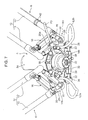
FIG. 1 is a perspective view of an industrial robot (as viewed obliquely from below) according to the present invention. -
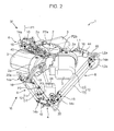
FIG. 2 is a perspective view of the industrial robot (as viewed obliquely from above). -
FIG. 3 is a side view showing an essential part of an arm. -
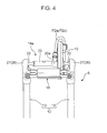
FIG. 4 is a front view showing an essential part of the arm (as viewed in the direction of the arrow IV inFIG. 2 ). -
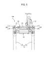
FIG. 5 is a sectional view (sectional view taken along the line V-V inFIG. 3 ) showing an essential part of the arm. -
FIG. 6 is a front view showing an essential part of the arm (as viewed in the direction of the arrow VI inFIG. 2 ). -
FIG. 7 is a perspective view of a head part (as viewed obliquely below). -
FIG. 8 is a side view (partially in sectional view) of the head part. -
FIG. 9 is a sectional view (sectional view taken along the IX-IX inFIG. 8 ) of the head part. -
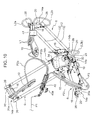
FIG. 10 is an explanatory view showing an arrangement of tubes (perspective view of arms and the head part). -
FIG. 11 is another explanatory view showing the arrangement of tubes (perspective view of the arms and the head part). -
FIG. 12A and FIG. 12B are graphs each showing changes in pressure within internal passages (changes in detection value of a pressure sensor),FIG. 12A showing a case where a second arm portion is disengaged andFIG. 12B showing a case where a second arm portion is likely to disengage. - An embodiment of the present invention will be described with reference to the accompanying drawings.
-
FIGS. 1 and2 are perspective views of anindustrial robot 1 according to the present invention. As shown in these figures, theindustrial robot 1 is of a parallel link type. - The industrial robot 1 (hereinafter, simply referred to as "
robot 1") includes abase part 2 serving as a support base to be secured to a ceiling or a frame member, ahead part 4 disposed below thebase part 2, and threearms 6 connected to thehead part 4 and configured to be respectively driven byarm driving motors 3 mounted on thebase part 2. Therobot 1 is so configured that the position and the orientation of thehead part 4 is changed by driving thearms 6 independently and in combination. - Three
motor supporters 2a are provided on thebase part 2 at regular intervals (at intervals of 120 degrees) around a vertical axis passing the center of thebase part 2. Themotor supporters 2a respectively fixedly support thearm driving motors 3. Each of thearm driving motors 3 is secured to thecorresponding motor supporter 2a in a horizontal position with an output shaft extending in a horizontal direction. Thearms 6 are respectively connected to the output shafts of thearm driving motors 3. - Each of the
arms 6 includes afirst arm portion 10 connected to the output shaft of thearm driving motor 3, asecond arm portion 12 connecting thefirst arm portion 10 and thehead part 4, afirst ball joint 14a pivotally connecting thefirst arm portion 10 and thesecond arm portion 12, and a second ball joint pivotally connecting thesecond arm portion 12 and thehead part 4. - As shown in
FIGS. 3 and4 , thearm portion 10 is in the form of an arch slightly tapering from a base end to a leading end in side view, the base end being secured to the output shaft of thearm driving motor 3. In this embodiment, thefirst arm portion 10 is in the form of a flat plate which is thin in the axial direction of the output shaft. However, thefirst arm portion 10 may be configured in the form of a box which is thick in the axial direction in order to enhance the strength. - As shown in
FIGS. 1 and2 , thesecond arm portion 12 includes a pair ofcylindrical rods 13 made of a light material such as carbon fiber. The pair ofrods 13 of thesecond arm portion 12 are connected to thefirst arm portion 10 via the first ball joint 14a and to thehead part 4 via the second ball joint 4b. Consequently, thesecond arm portion 12 is pivotally connected to thefirst arm portion 10 and thehead part 4. The configurations of the first ball joint 14a and the second ball joint 14b will be described in detail later. - As shown in
FIGS. 1 ,2 and7 , thehead part 4 includes abracket 30 connected with each of thearms 6, anozzle driving motor 34 secured on thebracket 30, and atool holder 32 rotatably supported on a central portion of thebracket 30 via a bearing or the like and configured to be driven by thenozzle driving motor 34. Thetool holder 32 detachably holds an end effector. - In this embodiment, various types of nozzles for sucking articles are detachably mounted as an end effector.
- Now, the configuration of the first ball joint 14a connecting the
first arm portion 10 and thesecond arm portion 12 and the configuration of the second ball joint 14b connecting thesecond arm portion 12 and thehead part 4 will be described. - As shown in
FIGS. 3 to 5 , the first ball joint 14a includes aball stud 20 secured to thefirst arm portion 10, and a pair ofsockets 26 respectively secured to the pair ofrods 13 and holding ball heads 22 of theball stud 20. - The
ball stud 20 is in the form of a shaft and has the ball heads 22 at its opposite ends. Theball stud 20 is secured to and passes through a leading end of thefirst arm portion 10 in the thickness direction of thefirst arm portion 10. - On the other hand, as shown in
FIG. 5 , each of the pair ofsockets 26 includes asocket body portion 27 secured to the correspondingrod 13, and a receivingportion 28 embedded in thesocket body portion 27 and receiving thecorresponding ball head 22. Thesockets 26 are respectively secured to upper ends of therods 13 and face each other, i.e. with therespective receiving portions 28 facing each other, and respectively hold the ball heads 22 via the receivingportions 28. - The second ball joint 14b basically has a similar configuration to the first ball joint 14b and includes, as shown in
FIGS. 7 to 9 , aball stud 20 provided with thehead part 4, and a pair ofsockets 26 respectively secured to lower ends of the pair ofrods 13 and holding ball heads 22 of theball stud 20. It should be noted that elements of the second ball joint 14a that are identical to those of the first ball joint 14a are denoted by the same reference numerals as those of the first ball joint 14a and detailed description thereof will be omitted. - The
ball stud 20 of the second ball joint 14b is integrally provided in thebracket 30 of thehead part 4. Specifically, as shown inFIG. 9 , a portion of theball stud 20 of the second ball joint 14b other than the ball heads 22 are molded integrally with thebracket 30 from the same material as thebracket 30. Subsequently, the ball heads 22 are assembled to thebracket 30. Consequently, theball studs 20 of the three second ball joints 14b connecting thesecond arm portions 12 are provided integrally in thebracket 30. - In each of the ball joints 14a and 14b, the receiving
portions 28 of thesockets 26 are relatively shallow with respect to the ball heads 22. For example, each of the receivingportions 28 is formed with a contacting surface having an area covering a half of the outside surface of theball head 22. This is to secure a range of pivot of thesecond arm portions 12 with respect to the correspondingfirst arm portions 10 and thehead part 4 as widely as possible, and to allow attachment and detachment of thesockets 26 to and from theball studs 20, i.e. attachment and detachment of thesecond arm portions 12 to and from thefirst arm portions 10 and thehead part 4. In such configuration, asocket 26 may easily disengage from thecorresponding ball stud 20, that is, asecond arm portion 12 may easily disengage from the correspondingfirst arm portion 10 or thehead part 4. Accordingly, as shown inFIG. 4 , a connectingmember 16 is mounted to and extends across thesocket body portions 27 of theopposite sockets 26 of each first ball joint 14a. Although not specifically shown, each connectingmember 16 is so configured to pull the pair ofrods 30 toward each other owing to a resilient force of a spring. This allows the ball heads 22 to be kept held by thesockets 26, i.e. allows thefirst arm portion 10 and thesecond arm portion 12 to be kept connected with each other. The same applies to thesockets 26 of each second ball joint 14b as shown inFIG. 7 , so that thehead part 4 and each ofsecond arm portions 12 are kept connected by connectingmembers 16. - However, during operation of the
robot 1, therods 13 constituting asecond arm portion 12 may be accidentally separated from each other by a certain factor, which results in disengagement of thesecond arm portion 12 from the correspondingfirst arm portion 10 or thehead part 4 at worst. Accordingly, therobot 1 includes the following configuration for detecting disengagement of any of thesecond arm portions 12 in order to stop immediately when the disengagement is detected. - As shown in
FIG. 5 , eachball stud 20 of thefirst ball joints 14a is formed with aninternal passage 23 extending axially and having openings on respective outside surfaces of the opposite ball heads 22. Theinternal passage 23 is supplied with air at a specific pressure via aport section 20a (seeFIG. 6 ) provided between the opposite ball heads 22. - The same applies to each of the second ball joints 14b, in which the
ball stud 20 is formed with aninternal passage 23 extending axially and having openings on respective outside surfaces of the opposite ball heads 22, as shown inFIGS. 8 and9 . The threeinternal passages 23 of theball studs 20 of the second ball joints 14b communicate with each other via bridge tubes (corresponding to a communication passage of the present invention) 38 provided in thebracket 30. Specifically, as shown inFIGS. 7 and9 , thebridge tubes 38 are provided between aspecific ball stud 20 and each of theball studs 20 disposed on both sides of the specific ball stud. Thus, the threeinternal passages 23 of the threeball studs 20 communicate with each other via thebridge tubes 38. In other words, the threeinternal passages 23 constitute a single passage. Consequently, air is supplied into theinternal passages 23 of theball studs 20 at the specific pressure via theport section 20a provided in thespecific ball stud 20. - Tubes for supplying air into the
internal passages 23 of theball studs 20 are arranged as follows. As shown inFIGS. 1 ,2 ,10 , and11 , thebase part 2 is equipped with anair distributor 40. Theair distributor 40 includes an input port having therein a flow regulating valve, and three output ports. The input port is connected with an unillustrated compressor by a first air tube P1, and the output ports are respectively connected with theport sections 20a of theball studs 20 of the threefirst ball joints 14a by second air tubes P2a to P2c. Each of the second air tubes P2a to P2c is arranged along a side surface of eachfirst arm portion 10 from thebase part 2. Theport section 20a of theball stud 20 of one of the threefirst ball joints 14a has two branch ports as shown inFIGS. 2 and6 , and is connected with theport 20a of thespecific ball stud 20 of the second ball joint 14b by a third air tube P3. The third air tube P3 is arranged along arod 13 and secured to therod 13 by a securing member such as tyingband 42, as shown inFIGS. 1 ,6 and7 . - As shown in
FIG. 1 , theair distributor 40 includes apressure sensor 40a for detecting a pressure in theinternal passages 23 of the ball joints 14a and 14b. Detection information obtained by thepressure sensor 40a is input into acontroller 50 which controls the entirety of therobot 1. To be precise, thepressure sensor 40a detects a pressure in the first air tube P1 (input port). The distance between thepressure sensor 40a and theinternal passages 23 is short and, therefore, the pressure in the first air tube P1 (input port) is substantially equal to the pressure in theinternal passages 23. Therefore, thepressure sensor 40a is provided in the first air tube P1 (input port) in this embodiment. - In
FIG. 2 , the reference signs L2a and L2b denote wires for controlling thenozzle driving motor 34. As shown inFIG. 2 , these wires L2a and L2b respectively pass through the pair ofrods 13 constituting asecond arm portion 12 with respective one ends extending out of therods 13 and connected to a connectingdevice 44 secured on a specificfirst arm portion 10 by a connector and the respective other ends extending out of therods 13 and connected to thenozzle driving motor 34 by a connector. Although not specifically shown, the connectingdevice 44 is connected to thecontroller 50 via a wire L1. - The
controller 50 is based on a known microcomputer, and includes a central processing unit (CPU) for executing a program, a memory including, for example, RAM and ROM for storing programs and data, and an input/output (I/O) bus for allowing input and output of an electrical signal. - The
controller 50 determines, based on detection information (detected pressure value) input from thepressure sensor 40a, whether any of thesecond arm portions 12 is disengaged from the correspondingfirst arm portion 10 or thehead part 4, and stops therobot 1 when the disengagement is determined. - Specifically, the
controller 50 determines that any of thesecond arm portions 12 of the threearms 6 is disengaged when the pressure value detected by thepressure sensor 40a continues to be less than a predetermined threshold value P, i.e. less than the pressure (the specific pressure) of air supplied into theinternal passages 23 by a predetermined value (corresponding to a first change amount of the present invention) or more, for a predetermined set time period T1 (corresponding to a first set time period of the present invention) or more as shown inFIG. 12A . In that case, thecontroller 50 causes therobot 1 to immediately stop the operation, and activates an alarming device 52 (seeFIG. 1 ) connected with thecontroller 50 to inform an operator of the disengagement. - In other words, air is supplied into the ball studs 20 (internal passages 23) of the ball joints 14a and 14b at the specific pressure. When the
second arm portions 12 are properly connected to the correspondingfirst arm portions 10 and thehead part 4, the pressure in theinternal passages 23 is kept at the specific pressure owing to the close contact between eachball head 22 of theball studs 20 and the corresponding receivingportion 28 of thesockets 26. However, when any of thesecond arm portions 12 disengages from the correspondingfirst arm portion 10 or thehead part 4, the ball stud 20 (ball heads 22) moves away from the sockets 26 (receiving portions 28) to open theinternal passage 23. Consequently, thepressure sensor 40a detects a lower pressure value. Thus, it is possible to detect disengagement of any of thesecond arm portions 12 by detecting a pressure in theinternal passages 23 by thepressure sensor 40a and comparing the detected pressure value with the threshold value P. - In this embodiment, the above-mentioned compressor, the tubes P1, P2a to P2c, P3 and the
air distributor 40 unitedly constitute a pressurizing device of the present invention, thepressure sensor 40a and thecontroller 50 unitedly constitute a determination device of the present invention, and these devices and theinternal passages 23 of theball studs 20 unitedly constitute a detector of the present invention. - As described above, the
robot 1 supplies air into theinternal passages 23 respectively formed in theball studs 20 of the ball joints 14a and 14b at a specific pressure and detects disengagement of any of thesecond arm portions 12 based on a pressure change in theinternal passages 23. Thus, the above-describedrobot 1 can detect disengagement of asecond arm portion 12 without applying an electric current to the ball joints. Therefore, unlike the conventional industrial robots of this type which detect disengagement of an arm based on electrical conduction between a ball stud and a socket, there is no likelihood of causing an electric shock at the time of maintenance. Consequently, it is possible to detect disengagement of any of thesecond arm portions 12 with a safer configuration. - Further, in the above-described
robot 1, each of thesecond arm portions 12 includes a pair ofrods 13, and the opposite ball heads 22 of eachball stud 20 are held by thesockets 26 secured to therods 13, whereby thesecond arm portions 12 are connected with the correspondingfirst arm portions 10 and thehead part 4. However, as described above, each of theinternal passages 23 extends in the axial direction of theball stud 20 and has openings on the respective outside surfaces of the opposite ball heads 22. Therefore, even when one of the pair ofrods 13 is disengaged, thepressure sensor 40a detects a lower pressure value. Thus, the above-describedrobot 1 is advantageous in that it is possible to successfully detect, not only complete disengagement of asecond arm portion 12 from the correspondingfirst arm portion 10 or thehead part 4, but also disengagement of arod 13 from the correspondingfirst arm portion 10 or thehead part 4. - Further, the
internal passages 23 of theball studs 20 of the second ball joints 14b communicate with each other in series via thebridge tubes 38. This makes it possible to supply air into a specific (one)ball stud 20 through the third air tube P3 to thereby supply the air into all of theinternal passages 23. Therefore, the above-describedrobot 1 is advantageous in that it is possible to simplify the layout of tubes around thehead part 4 and prevent the tubes for air supply from obstructing the operation of thearms 6 or an end effector. In addition, therobot 1 can be assembled more easily. - The above-described
robot 1 exemplifies a preferred embodiment of an industrial robot according to the present invention, and the specific configuration thereof may be appropriately changed without departing from the scope of the present invention. - For example, in the
robot 1 of the above-described embodiment, thecontroller 50 determines, based on a pressure value detected by thepressure sensor 40a, whether any of thesecond arm portions 12 is disengaged, and stops therobot 1 when the disengagement is determined. However, thecontroller 50 may also be configured to determine whether any of thesecond arm portions 12 is likely to disengage, and stop therobot 1 when the likelihood of disengagement is determined. Specifically, as shown inFIG. 12B , thecontroller 50 may be appreciated to count sudden reductions in detected pressure value in which the detected pressure value becomes less than the threshold value P only for a small time period shorter than the above-mentioned set time period T1, i.e. instantaneous deviations of the pressure in theinternal passages 23 from the pressure (the specific pressure) of air supplied into theinternal passages 23 by a predetermined value (corresponding to a second change amount of the present invention) or more, and determine, when the count exceeds a predetermined value within a predetermined set time period T2 (corresponding to a second set time period of the present invention), that there is a likelihood that any of thesecond arm portions 12 will disengage and stop therobot 1. Specifically, a long-term continuous operation of therobot 1 is liable to cause wear of aball head 22 of aball stud 20 or the receivingportion 28 of asocket 26, so that theball stud 20 is liable to easily disengage from thesocket 26, i.e. thesecond arm portion 12 is liable to easily disengage. Under such condition, air is liable to leak out of theinternal passage 23 due to deformation of theball head 22 or thesocket 26 caused by the above-mentioned wear. Consequently, there are repeated occurrences that the pressure value detected by thepressure sensor 40a suddenly becomes less than the threshold value P. Therefore, as described above, it is possible to determine the likelihood of disengagement of asecond arm portion 12 by counting the number of times that the pressure value detected by thepressure sensor 40a suddenly becomes less than the threshold value P. For example, an experimentally obtained value can be used for the threshold count value based on which the likelihood of disengagement of asecond arm portion 12 is determined. - Such configuration makes it possible to detect a likelihood of disengagement of any of the
second arm portions 12 to perform maintenance of thesecond arm portion 12 in advance. Consequently, it is advantageous in that actual disengagement of asecond arm portion 12 can be prevented. It should be noted that here thecontroller 50 has been described as determining disengagement and a likelihood of disengagement of any of thesecond arm portions 12. However, thecontroller 50 may be configured to only determine a likelihood of disengagement of any of thesecond arm portions 12. - In addition, the
robot 1 of the above-described embodiment can detect disengagement of any of the threesecond arm portions 12. Therobot 1 may be appreciated to specify whicharm 6 has a disengagedsecond arm portion 12. In this case, for example, eachball stud 20 ofsecond ball joints 14b is formed with an independentinternal passage 23, and ball studs (internal passages 23) of first andsecond ball joints arm 6 are connected in series by an air tube provided with apressure sensor 40a. This configuration makes it possible to detect disengagement of asecond arm portion 12 for eacharm 6 based on a pressure value detected by arespective air distributor 40. Therefore, it is possible to specify anarm 6 having a disengagedsecond arm portion 12. - Further, in the
robot 1 of the above-described embodiment, the third air tube P3 is arranged along the outer surface of arod 13 and secured to therod 13 by the tyingband 42. However, the third tube P3 may be arranged inside therod 13, similarly to the wires L2a and L2b used for controlling thenozzle driving motor 34. - Further, in the
robot 1 of the above-described embodiment, air is supplied into theinternal passages 23 of theball studs 20. Alternatively, therobot 1 may be configured such that air is sucked from theinternal passages 23. In other words, a specific negative pressure may be generated in theinternal passages 23 instead of supplying a specific positive pressure into theinternal passages 23, to determine that any of thesecond arm portions 12 is disengaged when the pressure value detected by thepressure sensor 40a continues to be greater than a predetermined threshold value for a predetermined set time period or more. In this case, a likelihood of disengagement of any of thesecond arm portions 12 may be determined based on the number of times that the pressure value detected by thepressure sensor 40a suddenly exceeds a threshold value. Such configuration also makes it possible to provide advantageous effects similar to those of the above-described embodiment. - The embodiments of the present invention described above can be summarized as follows.
- An industrial robot comprises: a base part; a plurality of motors mounted on the base part; a head part for holding an end effector; a plurality of arms provided for the plurality of motors, respectively, each arm including a first arm portion connected to the motor, a second arm portion connecting the first arm portion and the head part, a first ball joint pivotally connecting the first arm portion and the second arm portion, and a second ball joint pivotally connecting the second arm portion and the head part; and a detector for detecting a connection failure of a second arm portion, characterized in that: each of the first ball joints and the second ball joints includes a ball stud having a ball head, and a socket holding the ball head, each ball stud of at least either the first ball joints or the second ball joints includes an internal passage having an opening on an outside surface of the ball head, and the detector includes a pressurizing device for generating a specific pressure in the internal passages by supplying air into the internal passages or sucking air from the internal passages, and a determination device for detecting a pressure in the internal passages and determining based on a detected value whether a connection failure occurs in a second arm portion.
- Thus, when the second arm portions are normally connected to the first arm portions (or the head part), the pressure in the internal passages of the ball joints are maintained at the specific pressure. On the other hand, when a connection failure occurs in a second arm portion, specifically, when any of the second arm portions is disengaged from the corresponding first arm portion (or the head part) or has a likelihood of disengagement due to wear of a ball head or a socket, the internal passage of a ball joint is open, so that the pressure in the internal passages changes. In the above-described industrial robot, the determination device detects the above-mentioned connection failure of second arm portion based on such pressure change in the internal passages. This configuration makes it possible to detect a connection failure of a second arm portion without applying an electric current to the ball joints. Therefore, a connection failure of a second arm portion can be detected with a safer configuration.
- As a more specific configuration, each of the second arm portions includes a pair of a first rod and a second rod extending in parallel to each other, each of the first ball joints includes a socket secured at one end of the first rod and a socket secured at one end of the second rod, the both sockets facing each other, and a ball stud connected with a first arm portion and having ball heads facing in opposite directions, the ball heads being held by the sockets to thereby connect the first arm portion with the second arm portion, and each of the second ball joints includes a socket secured at the other end of the first rod and a socket secured at the other end of the second rod, the both sockets facing each other, and a ball stud connected with the head part and having ball heads facing in the opposite directions, the ball heads being held by the sockets to thereby connect the second arm portion with the head part, at least one of the first and second ball joints having an internal passage extending along an arrangement direction of the opposite ball heads and having openings on respective outside surfaces of the opposite ball heads.
- This configuration makes it possible to successfully detect such a connection failure that one of the pair of rods constituting a second arm portion is disengaged or is likely to disengage from the corresponding first arm portion (or the head part).
- In this case, particularly in the case where the ball studs of the second ball joints are formed with internal passages, respectively, it is preferred that the head part includes a communication passage connecting the respective internal passages of the ball studs of the second ball joints connecting the second arm portions, and that the pressurizing device supplies a specific pressure in the internal passage of a specific ball stud.
- This configuration makes it possible to simplify the layout of tubes for generating the specific pressure in the internal passages of the second ball joints.
- In this case, particularly in the case where the ball studs of the first ball joints and the second ball joints are formed with internal passages, respectively, it may be configured such that the pressurizing device includes a first tube communicating with one pressure supply source, a plurality of second tubes branching from the first tube and respectively connecting with the internal passages of the ball studs of the first ball joints, and a third tube branching from one of the second tubes and connecting with the internal passage of the specific ball stud.
- This configuration makes it possible to simply generate the specific pressure in the internal passages of the ball studs of the first ball joints and the second ball joints. In particular, only the single third tube is used for supplying the specific pressure to the second ball joints, which makes it possible to arrange (assemble) the tubes in an improved way and reduce influence on the operation of the arms.
- In addition, in the above-described industrial robot, the determination device determines a disengaged state of a second arm portion as the connection failure of the second arm portion, the disengaged state of the second arm portion being determined when the pressure in the internal passages is detected to continue to deviate from the specific pressure by a predetermined first change amount or more for a predetermined first set time period or more.
- This configuration makes it possible to successfully detect disengagement of a second arm portion.
- Further, in the above-described industrial robot, the determination device determines a likelihood of disengagement of a second arm portion as the connection failure of the second arm portion, the likelihood of disengagement of the second arm portion being determined when the pressure in the internal passages is detected to instantaneously deviate from the specific pressure by a predetermined second change amount a predetermined number of times or more within a predetermined second set time period.
- This configuration makes it possible to successfully detect a state that a second arm portion is likely to disengage due to wear of a ball head or a socket of a ball stud, i.e. likelihood of disengagement of a second arm portion.
Claims (6)
- An industrial robot, comprising:a base part (2);a plurality of motors (3) mounted on the base part (2);a head part (4) for holding an end effector;a plurality of arms (6) provided for the plurality of motors, each arm including
a first arm portion (10) connected to the motor (3),
a second arm portion (12) connecting the first arm portion (10) and the head part (4),
a first ball joint (14a) pivotally connecting the first arm portion (10) and the second arm portion (12), and
a second ball joint (14b) pivotally connecting the second arm portion (12) and the head part (4); anda detector (P1, P2a to P2c, P3, 40, 40a, 50) for detecting a connection failure of a second arm portion (12), characterized in that:each of the first ball joints (14a) and the second ball joints (14b) includes a ball stud (20) having a ball head (22), and a socket (26) holding the ball head (22),each ball stud (20) of at least either the first ball joints (14a) or the second ball joints (14b) includes an internal passage (23) having an opening on an outside surface of the ball head (22), andthe detector (P1, P2a to P2c, P3, 40, 40a, 50) includes a pressurizing device (P1, P2a to P2c, P3, 40) for generating a specific pressure in the internal passages (23) by supplying air into the internal passages (23) or sucking air from the internal passages (23), and a determination device (40a, 50) for detecting a pressure in the internal passages (23) and determining based on a detected value whether a connection failure occurs in a second arm portion (12). - An industrial robot according to claim 1, wherein:each of the second arm portions (12) includes a pair of a first rod (13) and a second rod (13) extending in parallel to each other;each of the first ball joints (14a) includes a socket (26) secured at one end of the first rod (13) and a socket (26) secured at one end of the second rod (13), the both sockets (26) facing each other, and a ball stud (20) connected with a first arm portion (10) and having ball heads (22) facing in opposite directions, the ball heads (22) being held by the sockets (26) to thereby connect the first arm portion (10) with the second arm portion (12); andeach of the second ball joints (14b) includes a socket (26) secured at the other end of the first rod (13) and a socket (26) secured at the other end of the second rod (13), the both sockets (26) facing each other, and a ball stud (20) connected with the head part (4) and having ball heads (22) facing in the opposite directions, the ball heads (22) being held by the sockets (26) to thereby connect the second arm portion (12) with the head part (4), at least one of the first and second ball joints (14a, 14b) having an internal passage (23) extending along an arrangement direction of the opposite ball heads (22) and having openings on respective outside surfaces of the opposite ball heads (22).
- An industrial robot according to claim 1 or 2, wherein:the ball studs (20) of the second ball joints (14b) are formed with the internal passages (23), respectively:the head part (4) includes a communication passage (38) connecting the respective internal passages (23) of the ball studs (20) of the second ball joints (14b) connecting the second arm portions (12); andthe pressurizing device (P1, P2a to P2c, P3, 40) supplies a specific pressure in the internal passage (23) of a specific ball stud (20).
- An industrial robot according to claim 3, wherein:the ball studs (20) of the first ball joints (14a) and the second ball joints (14b) are formed with the internal passages (23), respectively, andthe pressurizing device (P1, P2a to P2c, P3, 40) includes a first tube (P1) communicating with one pressure supply source, a plurality of second tubes (P2a to P2c) branching from the first tube (P1) and respectively connecting with the internal passages (23) of the ball studs (20) of the first ball joints (14a), and a third tube (P3) branching from one of the second tubes (P2a to P2c) and connecting with the internal passage (23) of the specific ball stud (20).
- An industrial robot according to any one of claims 1 to 4, wherein
the determination device (40a, 50) determines a disengaged state of a second arm portion (12) as the connection failure of the second arm portion (12), the disengaged state of the second arm portion (12) being determined when the pressure in the internal passages (23) is detected to continue to deviate from the specific pressure by a predetermined first change amount or more for a predetermined first set time period or more. - An industrial robot according to any one of claims 1 to 5, wherein
the determination device (40a, 50) determines a likelihood of disengagement of a second arm portion (12) as the connection failure of the second arm portion (12), the likelihood of disengagement of the second arm portion (12) being determined when the pressure in the internal passages (23) is detected to instantaneously deviate from the specific pressure by a predetermined second change amount a predetermined number of times or more within a predetermined second set time period.
Applications Claiming Priority (1)
| Application Number | Priority Date | Filing Date | Title |
|---|---|---|---|
| JP2015130867A JP6502194B2 (en) | 2015-06-30 | 2015-06-30 | Industrial robot |
Publications (1)
| Publication Number | Publication Date |
|---|---|
| EP3112093A1 true EP3112093A1 (en) | 2017-01-04 |
Family
ID=54478546
Family Applications (1)
| Application Number | Title | Priority Date | Filing Date |
|---|---|---|---|
| EP15003182.1A Withdrawn EP3112093A1 (en) | 2015-06-30 | 2015-11-06 | Industrial robot |
Country Status (3)
| Country | Link |
|---|---|
| EP (1) | EP3112093A1 (en) |
| JP (1) | JP6502194B2 (en) |
| CN (1) | CN106313001A (en) |
Cited By (4)
| Publication number | Priority date | Publication date | Assignee | Title |
|---|---|---|---|---|
| JP2018122320A (en) * | 2017-01-31 | 2018-08-09 | アイダエンジニアリング株式会社 | Work transfer device for press machine |
| IT202300012576A1 (en) * | 2023-06-19 | 2024-12-19 | Zodiac Robotics S R L | IMPROVED DELTA-TYPE INDUSTRIAL ROBOT |
| IT202300012579A1 (en) * | 2023-06-19 | 2024-12-19 | Zodiac Robotics S R L | IMPROVED DELTA-TYPE INDUSTRIAL ROBOT INCLUDING A CONNECTING ELEMENT |
| WO2024259529A1 (en) * | 2023-06-20 | 2024-12-26 | Industries Machinex Inc. | Pneumatic system for detecting robotized arm disconnection |
Families Citing this family (5)
| Publication number | Priority date | Publication date | Assignee | Title |
|---|---|---|---|---|
| JP6846717B2 (en) | 2018-02-14 | 2021-03-24 | ファナック株式会社 | Robot joint abnormality detection device and abnormality detection method |
| JP7029681B2 (en) * | 2020-03-18 | 2022-03-04 | 株式会社安川電機 | Robot control device, robot control system, and robot control method |
| CN111687864B (en) * | 2020-06-28 | 2021-01-12 | 清华大学 | Adsorption type parallel machining robot |
| US20240051131A1 (en) | 2021-01-18 | 2024-02-15 | Fanuc Corporation | Gap detection device and gap detection method for robot joint |
| WO2023175706A1 (en) * | 2022-03-15 | 2023-09-21 | ファナック株式会社 | Parallel link robot |
Citations (5)
| Publication number | Priority date | Publication date | Assignee | Title |
|---|---|---|---|---|
| EP1072366A1 (en) * | 1999-07-23 | 2001-01-31 | Marc-Olivier Demaurex | Conveyor apparatus |
| DE102008025845A1 (en) * | 2008-05-29 | 2009-12-03 | Festo Ag & Co. Kg | Drive system, has coupling struts clamped together by spring in transverse direction for retaining components in opposite intervention, and detection unit producing output of electrical warning signal when components reach intervention |
| US20100101359A1 (en) * | 2007-01-29 | 2010-04-29 | Robert Bosch Gmbh | Device for displacing and positioning an object in space |
| JP4850863B2 (en) | 2008-04-10 | 2012-01-11 | 村田機械株式会社 | Parallel mechanism |
| EP2567795A2 (en) * | 2011-09-06 | 2013-03-13 | Kabushiki Kaisha Yaskawa Denki | Parallel link robot, parallel link robot system, and method of controlling parallel link robot |
Family Cites Families (3)
| Publication number | Priority date | Publication date | Assignee | Title |
|---|---|---|---|---|
| CH672089A5 (en) * | 1985-12-16 | 1989-10-31 | Sogeva Sa | |
| GB0716796D0 (en) * | 2007-08-29 | 2007-10-10 | Renishaw Plc | Pivot joint assembley |
| JP4420959B2 (en) * | 2008-04-10 | 2010-02-24 | 村田機械株式会社 | Parallel mechanism |
-
2015
- 2015-06-30 JP JP2015130867A patent/JP6502194B2/en active Active
- 2015-11-06 EP EP15003182.1A patent/EP3112093A1/en not_active Withdrawn
- 2015-11-10 CN CN201510763299.0A patent/CN106313001A/en active Pending
Patent Citations (5)
| Publication number | Priority date | Publication date | Assignee | Title |
|---|---|---|---|---|
| EP1072366A1 (en) * | 1999-07-23 | 2001-01-31 | Marc-Olivier Demaurex | Conveyor apparatus |
| US20100101359A1 (en) * | 2007-01-29 | 2010-04-29 | Robert Bosch Gmbh | Device for displacing and positioning an object in space |
| JP4850863B2 (en) | 2008-04-10 | 2012-01-11 | 村田機械株式会社 | Parallel mechanism |
| DE102008025845A1 (en) * | 2008-05-29 | 2009-12-03 | Festo Ag & Co. Kg | Drive system, has coupling struts clamped together by spring in transverse direction for retaining components in opposite intervention, and detection unit producing output of electrical warning signal when components reach intervention |
| EP2567795A2 (en) * | 2011-09-06 | 2013-03-13 | Kabushiki Kaisha Yaskawa Denki | Parallel link robot, parallel link robot system, and method of controlling parallel link robot |
Cited By (5)
| Publication number | Priority date | Publication date | Assignee | Title |
|---|---|---|---|---|
| JP2018122320A (en) * | 2017-01-31 | 2018-08-09 | アイダエンジニアリング株式会社 | Work transfer device for press machine |
| IT202300012576A1 (en) * | 2023-06-19 | 2024-12-19 | Zodiac Robotics S R L | IMPROVED DELTA-TYPE INDUSTRIAL ROBOT |
| IT202300012579A1 (en) * | 2023-06-19 | 2024-12-19 | Zodiac Robotics S R L | IMPROVED DELTA-TYPE INDUSTRIAL ROBOT INCLUDING A CONNECTING ELEMENT |
| EP4480642A1 (en) * | 2023-06-19 | 2024-12-25 | Zodiac Robotics S.r.l. | Improved delta-type industrial robot comprising a connecting element |
| WO2024259529A1 (en) * | 2023-06-20 | 2024-12-26 | Industries Machinex Inc. | Pneumatic system for detecting robotized arm disconnection |
Also Published As
| Publication number | Publication date |
|---|---|
| CN106313001A (en) | 2017-01-11 |
| JP6502194B2 (en) | 2019-04-17 |
| JP2017013160A (en) | 2017-01-19 |
Similar Documents
| Publication | Publication Date | Title |
|---|---|---|
| JP6502194B2 (en) | Industrial robot | |
| CN105659720B (en) | Lead cuts and clenches device | |
| US10350758B2 (en) | Robot control unit for assembly robot | |
| US9604357B2 (en) | Robot and device having multi-axis motion sensor, and method of use thereof | |
| CN105965128B (en) | Monitor the welding robot of the feeding of welding wire | |
| SE1000373A1 (en) | Device for controlling hoses and / or cables | |
| CN102481692B (en) | Collision protection device | |
| US11577405B2 (en) | Robot hand and robot system | |
| US20160031086A1 (en) | Mobile collaborative robot | |
| US9643277B2 (en) | Robot | |
| JP2012127497A (en) | Ball joint having passageway for routing cable therethrough | |
| US20190134828A1 (en) | Robotic accessory mounting assembly | |
| US20190160688A1 (en) | Robot | |
| US10610952B2 (en) | Welding wire processing structure of arc welding robot | |
| CN114162668B (en) | Broken wire clamping device | |
| CN113442116A (en) | Flexible clamping mechanism for tail end of robot and robot | |
| US20190255590A1 (en) | Die and device for positioning a joining element or for clinch joining | |
| CN113021903B (en) | Pressure detection assembly and ultrasonic welding equipment | |
| KR101914688B1 (en) | The connection module for installation of gripper | |
| JP2015085449A (en) | robot | |
| CN103516123A (en) | Motor having lead screw | |
| US20200108511A1 (en) | Sensor bracket and robot system | |
| US10596664B2 (en) | Robot | |
| CN113275858A (en) | Temperature controller assembly machine | |
| JP7198133B2 (en) | MOISTURE INTRUSION DETECTION SYSTEM AND MOISTURE INTRUSION DETECTION METHOD |
Legal Events
| Date | Code | Title | Description |
|---|---|---|---|
| PUAI | Public reference made under article 153(3) epc to a published international application that has entered the european phase |
Free format text: ORIGINAL CODE: 0009012 |
|
| STAA | Information on the status of an ep patent application or granted ep patent |
Free format text: STATUS: REQUEST FOR EXAMINATION WAS MADE |
|
| 17P | Request for examination filed |
Effective date: 20151126 |
|
| AK | Designated contracting states |
Kind code of ref document: A1 Designated state(s): AL AT BE BG CH CY CZ DE DK EE ES FI FR GB GR HR HU IE IS IT LI LT LU LV MC MK MT NL NO PL PT RO RS SE SI SK SM TR |
|
| AX | Request for extension of the european patent |
Extension state: BA ME |
|
| RBV | Designated contracting states (corrected) |
Designated state(s): AL AT BE BG CH CY CZ DE DK EE ES FI FR GB GR HR HU IE IS IT LI LT LU LV MC MK MT NL NO PL PT RO RS SE SI SK SM TR |
|
| GRAP | Despatch of communication of intention to grant a patent |
Free format text: ORIGINAL CODE: EPIDOSNIGR1 |
|
| STAA | Information on the status of an ep patent application or granted ep patent |
Free format text: STATUS: GRANT OF PATENT IS INTENDED |
|
| INTG | Intention to grant announced |
Effective date: 20210201 |
|
| RAP1 | Party data changed (applicant data changed or rights of an application transferred) |
Owner name: YAMAHA HATSUDOKI KABUSHIKI KAISHA |
|
| STAA | Information on the status of an ep patent application or granted ep patent |
Free format text: STATUS: THE APPLICATION IS DEEMED TO BE WITHDRAWN |
|
| 18D | Application deemed to be withdrawn |
Effective date: 20210612 |