EP3111858A2 - Anvil assemblies and delivery systems - Google Patents
Anvil assemblies and delivery systems Download PDFInfo
- Publication number
- EP3111858A2 EP3111858A2 EP16177440.1A EP16177440A EP3111858A2 EP 3111858 A2 EP3111858 A2 EP 3111858A2 EP 16177440 A EP16177440 A EP 16177440A EP 3111858 A2 EP3111858 A2 EP 3111858A2
- Authority
- EP
- European Patent Office
- Prior art keywords
- suture
- assembly
- anvil
- head assembly
- adapter
- Prior art date
- Legal status (The legal status is an assumption and is not a legal conclusion. Google has not performed a legal analysis and makes no representation as to the accuracy of the status listed.)
- Granted
Links
- 230000000712 assembly Effects 0.000 title description 9
- 238000000429 assembly Methods 0.000 title description 9
- 238000000034 method Methods 0.000 claims description 46
- 238000003780 insertion Methods 0.000 description 10
- 230000037431 insertion Effects 0.000 description 10
- 238000010304 firing Methods 0.000 description 6
- 210000002784 stomach Anatomy 0.000 description 6
- 239000000463 material Substances 0.000 description 4
- 238000001356 surgical procedure Methods 0.000 description 4
- 239000000853 adhesive Substances 0.000 description 3
- 230000001070 adhesive effect Effects 0.000 description 3
- 210000003238 esophagus Anatomy 0.000 description 3
- 210000002438 upper gastrointestinal tract Anatomy 0.000 description 3
- 229920002799 BoPET Polymers 0.000 description 2
- 239000005041 Mylar™ Substances 0.000 description 2
- -1 polyethylene Polymers 0.000 description 2
- 208000010496 Heart Arrest Diseases 0.000 description 1
- 239000004698 Polyethylene Substances 0.000 description 1
- 239000004743 Polypropylene Substances 0.000 description 1
- 230000009286 beneficial effect Effects 0.000 description 1
- 239000011248 coating agent Substances 0.000 description 1
- 238000000576 coating method Methods 0.000 description 1
- 238000010276 construction Methods 0.000 description 1
- 210000001035 gastrointestinal tract Anatomy 0.000 description 1
- 208000014617 hemorrhoid Diseases 0.000 description 1
- 238000002372 labelling Methods 0.000 description 1
- 239000002184 metal Substances 0.000 description 1
- 229920000573 polyethylene Polymers 0.000 description 1
- 229920001155 polypropylene Polymers 0.000 description 1
- 125000006850 spacer group Chemical group 0.000 description 1
- 238000003466 welding Methods 0.000 description 1
Images


Classifications
-
- A—HUMAN NECESSITIES
- A61—MEDICAL OR VETERINARY SCIENCE; HYGIENE
- A61B—DIAGNOSIS; SURGERY; IDENTIFICATION
- A61B17/00—Surgical instruments, devices or methods, e.g. tourniquets
- A61B17/04—Surgical instruments, devices or methods, e.g. tourniquets for suturing wounds; Holders or packages for needles or suture materials
- A61B17/0469—Suturing instruments for use in minimally invasive surgery, e.g. endoscopic surgery
-
- A—HUMAN NECESSITIES
- A61—MEDICAL OR VETERINARY SCIENCE; HYGIENE
- A61B—DIAGNOSIS; SURGERY; IDENTIFICATION
- A61B17/00—Surgical instruments, devices or methods, e.g. tourniquets
- A61B17/11—Surgical instruments, devices or methods, e.g. tourniquets for performing anastomosis; Buttons for anastomosis
- A61B17/115—Staplers for performing anastomosis in a single operation
- A61B17/1155—Circular staplers comprising a plurality of staples
-
- A—HUMAN NECESSITIES
- A61—MEDICAL OR VETERINARY SCIENCE; HYGIENE
- A61B—DIAGNOSIS; SURGERY; IDENTIFICATION
- A61B17/00—Surgical instruments, devices or methods, e.g. tourniquets
- A61B2017/0046—Surgical instruments, devices or methods, e.g. tourniquets with a releasable handle; with handle and operating part separable
- A61B2017/00473—Distal part, e.g. tip or head
-
- A—HUMAN NECESSITIES
- A61—MEDICAL OR VETERINARY SCIENCE; HYGIENE
- A61B—DIAGNOSIS; SURGERY; IDENTIFICATION
- A61B17/00—Surgical instruments, devices or methods, e.g. tourniquets
- A61B2017/00743—Type of operation; Specification of treatment sites
- A61B2017/00818—Treatment of the gastro-intestinal system
Abstract
Description
- The present disclosure relates to an anvil assemblies for use with a surgical stapling device. More particularly, the present disclosure relates to a delivery system for trans-oral delivery of the anvil assemblies.
- Trans-oral delivery systems for delivering an anvil assembly to a surgical site, e.g., the stomach, typically include a guide suture threaded through one or more openings in the head of the anvil assembly to facilitate trans-oral insertion of the anvil assembly. The guide suture, which includes ends that remain external of the patient's mouth, may be used by the surgeon to dislodge the anvil assembly if the anvil assembly becomes stuck during trans-oral delivery of the anvil assembly and/or to retrieve the anvil assembly in the event of a patient emergency, e.g., cardiac arrest. Improved methods for securing the guide suture to the anvil assembly to facilitate detachment of the guide suture from the anvil assembly once the anvil assembly is delivered to the surgical site and/or the stapling procedure has been performed are desirable.
- An anvil delivery system is provided. The anvil delivery system includes a delivery assembly an anvil assembly selectively securable to the delivery assembly and including a center rod assembly selectively securable to the delivery assembly and a head assembly pivotally secured to the center rod assembly between a first tilted position and an operative position. The anvil delivery system further including a suture extending from the anvil delivery system through the head assembly and distally of the head assembly, wherein the suture retains the head assembly in the first tilted position.
- In embodiments, the head assembly includes a housing that defines a first proximal opening and a second proximal opening, the suture extending through each of the first and second proximal openings. The delivery assembly may include a flexible member and an adapter. The suture may extend through the adapter. The suture may be frictionally secured between the flexible member and the adapter. The suture may extend from the first proximal opening through the adapter and to the second proximal opening. A first portion of the suture may cross over a second portion of the suture between the head assembly and the adapter. The suture may include a loop extending distally of the head assembly. The head assembly may be movable to a second tilted position opposite the first tilted position.
- Also provided is a method of securing an anvil assembly in a first tilted position. The method includes receiving a first end of a suture through a first opening in a head assembly of an anvil assembly, receiving the first end of the suture through a bore in an adapter secured to a center rod assembly of the anvil assembly, receiving the first end of the suture back through a second opening in the head assembly, and tying the first end of the suture to a second end of the suture adjacent the head assembly.
- In embodiments, the method further includes moving the head assembly relative to the center rod assembly prior to tying the first end of the suture to the second end of the suture. Moving the head assembly relative to the center rod assembly may include pivoting the head assembly to a first tilted position. Receiving the first end of the suture through a first opening may include receiving the first end of the suture into a first distal opening and out a first proximal opening. Receiving the first end of the suture through a second opening may include receiving the first end of the suture into a second proximal opening and out of a second distal opening.
- Another method of securing an anvil assembly in a first tilted position is also provided. The method includes receiving a first end of a suture through a first opening in a head assembly of an anvil assembly, receiving a second end of the suture through a second opening in the head assembly, receiving the first and second ends of the suture through a bore in an adapter, and securing the adapter to a flexible member such that the suture is secured within the bore.
- In embodiments, receiving the first and second ends of the suture through a bore includes receiving the first end of the suture through a first bore in a first direction and receiving the second end of the suture through the first bore in a second direction, then receiving the first end of the suture through a second bore in the second direction and receiving the second end of the suture through the second bore in the first direction. Securing the adapter to the flexible member may include receiving a first end of the adapter within an open end of the flexible member.
- Various embodiments of the presently disclosed anvil assembly and anvil assembly delivery system are disclosed herein with reference to the drawings wherein:
-
FIG. 1 is a perspective view of a surgical stapling device including an embodiment of an anvil assembly according to the present disclosure; -
FIG. 2 is a first perspective side view of the anvil assembly ofFIG. 1 ; -
FIG. 3 is a second perspective side view of the anvil assembly shown inFIGS. 1 and2 ; -
FIG. 4 is an exploded side view of the anvil assembly ofFIGS. 1-3 ; -
FIG. 5 is an end view of the anvil assembly ofFIGS. 1-4 ; -
FIG. 6 is a cross-sectional side view of a distal end of the tilt anvil assembly ofFIGS. 1-6 taken along line 6-6 ofFIG. 5 ; -
FIG. 7 is a cross-sectional side view of a distal end of the anvil assembly ofFIGS. 1-6 taken along line 7-7 ofFIG. 5 ; -
FIG. 8 is an enlarged side view of the cam latch member of the anvil assembly ofFIGS. 1-7 ; -
FIG. 9 is a top view of the anvil assembly ofFIGS. 1-7 supported on an anvil delivery system; -
FIG. 10 is an enlarged exploded view of the anvil delivery system ofFIG. 9 ; -
FIG. 11 an enlarged top view of the anvil delivery system ofFIGS. 9 and 10 , including the anvil assembly ofFIGS. 1-7 ; -
FIG. 12 is a cross-sectional side view of the anvil assembly and anvil assembly delivery system ofFIG. 11 taken along lines 12-12 ofFIG. 11 ; -
FIG. 13 is a cross sectional side view of the anvil assembly ofFIGS. 1-7 , in a pre-fired tilted position supported on the anvil delivery system ofFIGS. 9-12 ; -
FIG. 14 is an enlarged view of the indicated area of detail shown inFIG. 13 ; -
FIG. 15 is an illustration of the anvil assembly and anvil delivery system ofFIGS. 11 and 12 being inserted trans-orally into a patient; -
FIG. 16 is an enlarged side view of the distal head portion of the surgical stapling device ofFIG. 1 with the anvil assembly removed; -
FIG. 17 is an enlarged side view of the distal head portion of the surgical stapling device ofFIG. 1 with the anvil assembly ofFIGS. 1-7 received thereon; -
FIG. 18 is an enlarged cross-sectional side view of the distal head portion of the surgical stapling device of FIG. land the anvil assembly ofFIGS. 1-7 in a pre-fired non-tilted operative position; -
FIG. 19 is an enlarged cross-sectional side view of the distal head portion of the surgical stapling device of FIG. land the anvil assembly ofFIGS. 1-7 in a post-fired non-titled operative position; -
FIG. 20 is an enlarged cross-sectional side view of the distal end of the anvil assembly ofFIGS. 1-7 in the post-fired operative position; -
FIG. 21 is an enlarged cross-sectional side view of the distal end of the anvil assembly ofFIGS. 1-7 in a post-fired tilted position; -
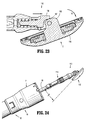
FIG. 22 is a cross-sectional side view of the anvil assembly ofFIGS. 1-7 in a post-fired tilted position supported on an anvil retainer of the surgical instrument ofFIG. 1 ; -
FIG. 22A is another cross-sectional side view of the anvil assembly ofFIGS. 1-7 in a post-fired tilted position supported on an anvil retainer of the surgical instrument ofFIG. 1 -
FIG. 23 is an enlarged view of the indicated area of detail shown inFIG.22A ; -
FIG. 24 is a side view of the anvil assembly ofFIG. 22 supported on the anvil retainer of the surgical stapling device ofFIG. 1 ; -
FIG. 25 is a perspective side view of an anvil assembly according to another embodiment of the present disclosure in an operative position; -
FIG. 26 is a perspective bottom view of the anvil assembly ofFIG. 25 , in a first tilted position and with a backup plate/cutting ring assembly removed; -
FIG. 27 is a top view of the anvil assembly ofFIG. 25 and a distal portion of the anvil delivery system ofFIG. 11 with parts separated, and a suture as the suture is secured to the anvil assembly and anvil delivery system in a first configuration; -
FIG. 28 is a top view of the anvil assembly, anvil delivery assembly, and suture ofFIG. 27 , with the anvil delivery system secured to the anvil assembly and the suture secured to the anvil assembly and the anvil delivery system in the first configuration; -
FIG. 29 is a top view of the anvil assembly ofFIG. 25 and a distal portion of the anvil delivery system ofFIG. 11 with parts separated, and a suture as the suture is secured to the anvil assembly and anvil delivery system in a second configuration; -
FIG. 30 is a top view of the anvil assembly, anvil delivery assembly, and suture ofFIG. 29 , with an adapter of the anvil delivery system secured to the anvil assembly and as the suture is secured to the anvil assembly and the anvil delivery system in the second configuration; -
FIG. 31 is a top view of the anvil assembly, anvil delivery assembly, and suture ofFIG. 29 , with the anvil delivery system secured to the anvil assembly and the suture secured to the anvil assembly and the anvil delivery system in the second configuration; -
FIG. 32 is a top view of the anvil assembly, anvil delivery assembly, and suture ofFIG. 29 , with the anvil delivery system secured to the anvil assembly and the suture secured to the anvil assembly and the anvil delivery system in a third configuration; and -
FIG. 33 is a perspective side view of the anvil assembly, anvil delivery assembly, and suture ofFIG. 32 , further including a suture reel. - Embodiments of the presently disclosed anvil assembly delivery system will now be described in detail with reference to the drawings in which like reference numerals designate identical or corresponding elements in each of the several views. Throughout this description, the term "proximal" will refer to the portion of the instrument closest to the operator and the term "distal" will refer to the portion of the instrument furthest from the operator.
-
FIG. 1 illustrates an embodiment of a surgical stapling device configured for use with tilt anvil assemblies and anvil delivery systems according to the present disclosure. Although the anvil assemblies and anvil delivery systems of the present disclosure will be described with reference tosurgical stapling device 10, it is envisioned that the anvil assemblies and anvil delivery systems may be modified for use with alternative surgical stapling devices. - Briefly, the
surgical stapling device 10 includes aproximal handle assembly 12, an elongatedcentral body portion 14 including a curved elongatedouter tube 14a, and adistal head portion 16. Alternately, in some surgical procedures, e.g., the treatment of hemorrhoids, it is desirable to have a substantially straight, shortened, central body portion. The length, shape and/or the diameter of thebody portion 14 and thedistal head portion 16 may also be varied to suit a particular surgical procedure. - With reference still to
FIG. 1 , thehandle assembly 12 includes astationary handle 18, a firingtrigger 20, arotatable approximation knob 22 and anindicator 24. A pivotally mountedtrigger lock 26 is fastened to thehandle assembly 12 and is manually positioned to prevent inadvertent firing of the staplingdevice 10. Theindicator 24 is positioned on thestationary handle 18 and includes indicia, e.g., color coding, alpha-numeric labeling, etc., to identify to a surgeon whether the device is approximated and is ready to be fired. Thehead portion 16 includes ananvil assembly 110 and ashell assembly 31. For a more detailed discussion of an exemplary surgical stapler, please refer to commonly ownedU.S. Patent No. 7,364,060 to Milliman, the content of which is incorporated herein by reference in its entirety. - Referring now to
FIGS. 2-7 , an anvil assembly according to an embodiment of the present disclosure is shown generally asanvil assembly 110. Theanvil assembly 110 is shown in a non-titled position or operative position. Theanvil assembly 110 includes ahead assembly 112 and acenter rod assembly 114. Thehead assembly 112 includes apost 116, ahousing 118, a backup member orplate 120, acutting ring 122, a cuttingring cover 123, ananvil plate 124, a spacer orwasher 125, acam latch member 126, and aretainer member 127. Thepost 116 is monolithically formed with and centrally positioned within thehousing 118. Alternately, thehousing 118 and thepost 116 may be formed separately and fastened together using a known fastening technique, e.g., welding. - As will be discussed in further detail below, the
housing 118 includesopenings FIG. 9 ) is inserted throughopenings 119a and is used to retain thehead assembly 112 in a retracted or first tilted position (FIG. 9 ) during insertion of theanvil assembly 110 within a patient. A second suture "S2" (FIG. 9 ) is inserted through theopenings 119b. The second suture "S2" is configured to facilitate guiding theanvil assembly 110 trans-orally within a patient. During trans-oral insertion of theanvil assembly 110, the second suture "S2" extends from the mouth "M" (FIG. 15 ) of patient, permitting theanvil assembly 110 to be retrieved trans-orally. - With reference still to
FIGS. 2-7 , theanvil plate 124 is supported in an outerannular recess 128 of thehousing 118 and includes a plurality ofstaple deforming pockets 130 for receiving and deforming staples. At least onetab 124a extends radially outwardly from theanvil plate 124 and is received within acutout 132 formed in an outer rim of thehousing 118. Thetab 124a and thecutout 132 function to align or properly position theanvil plate 124 within theannular recess 128 of thehousing 118. - With particular reference to
FIGS. 6 and 7 , thehead assembly 112 will be described in detail. Thebackup plate 120 includes acentral opening 134 which is positioned about thepost 116 within an innerannular recess 136 of thehousing 118 between thepost 116 and the outerannular recess 128. Thebackup plate 120 includes a raisedplatform 120a. The cuttingring 122 includes anopening 122a having a configuration substantially the same as theplatform 120a. Although theplatform 120a is illustrated as having a circular shape, other configurations are envisioned, e.g., square, rectangular, triangular, etc. In one embodiment, the cuttingring 122 is formed from polyethylene and is fixedly secured to thebackup plate 120 using, for example, an adhesive, to form a backup plate/cutting ring assembly. Thebackup plate 120 is formed from a hard material, e.g., a metal. Alternately other materials of construction may be used to construct thebackup plate 120 and thecutting ring 122. Further, thebackup plate 120 and thecutting ring 122, in the alternative, can be formed as a single or unitary structure. - Still referring to
FIGS. 6 and 7 , a cuttingring cover 123 is secured to an outwardly facing or proximal surface of thecutting ring 122 using, for example, an adhesive. In one embodiment, the cuttingring cover 123 is formed from a material or materials, having a hardness greater than that of the cutting ring, e.g., mylar. In one embodiment, the cuttingring cover 123 includes two layers of mylar (not shown) which are joined together using an adhesive and a polypropylene coating. Alternately, the cuttingring 122 does not include a cover. The cuttingring 122 and thebackup plate 120 are slidably mounted about thepost 116. Thebackup plate 120 includes a pair of inwardly extendingfingers 138 which will be described in further detail below. - With reference still to
FIGS. 6 and 7 , theretainer member 127 is positioned in the innerannular recess 136 between thebackup plate 120 and aback wall 118a of thehousing 118. In one embodiment, theretainer member 127 is annular and includes a plurality ofdeformable tabs 127a which engage a rear surface of thebackup plate 120. Theretainer member 127 prevents thebackup plate 120 and thecutting ring 122 from moving or being pushed into the innerannular recess 136 of thehousing 118 until a predetermined force sufficient to deform thetabs 127a has been applied to the backup plate/cutting ring assembly. The predetermined force can be close to but is less than the force applied by an annular cutting blade of a surgical stapling device when it engages, for example, the cutting ring of theanvil assembly 110. In one embodiment by way of example, the predetermined force is between about ten pounds and about ninety pounds and can be about thirty (30) pounds. When the predetermined force is reached, e.g., during cutting of tissue, thebackup plate 120 is urged into the innerannular recess 136 and compresses theretainer member 127. - It is envisioned that other crushable, deformable, collapsible or movement restricting members may be used to retain the backup plate/cutting ring assembly in a fixed position until a predetermined force has been applied to the backup plate/cutting ring assembly. An exemplary retaining member is described in commonly owned
U.S. Patent Application Serial No. 14/078,766 , the content of which is incorporated by reference herein in its entirety. - Turning back to
FIG. 4 , the anvilcenter rod assembly 114 includes acenter rod 152, aplunger 154, andplunger spring 156. A first end ofcenter rod 152 includes a pair ofarms 159 which define acavity 159a. Eacharm 159 has atransverse throughbore 158 which is aligned with a central longitudinal axis of thecenter rod 152. Alternately, thethroughbores 158 can be offset from the longitudinal axis of thecenter rod 152. Thepost 116 of thehead assembly 112 is dimensioned to be positioned within thecavity 159a and also includes a transverse throughbore (not shown). Apivot member 162 pivotally secures thepost 116 to thecenter rod 152 via thethroughbores 158 such that thehead assembly 112 may be pivotally mounted to the anvilcenter rod assembly 114. - Turning briefly to
FIG. 8 , thecam latch member 126 includes abody 126a having a throughbore 126b. The throughbore 126b is dimensioned to receive thepivot member 162 such that thecam latch member 126 is pivotally mounted within the transverse slot 172 (FIG. 3 ) of thepost 116 about thepivot member 162. Referring now toFIGS. 3 ,6 and 7 , thecam latch member 126 includes abody portion 126c which extends partially from thetransverse slot 172 of thepost 116 and is positioned to be engaged by afinger 166 of theplunger 154. Thebody portion 126c is configured such that the distance between the surface of thebody portion 126c and the throughbore 126b increase in a clockwise direction about thecam latch member 126. In this manner, theplunger 154 is able to move forward as thecam latch member 126 rotates in a clockwise direction. Additionally, this configuration of thebody portion 126c permits theplunger 154 to be retracted as thecam latch member 126 rotates in a counter-clockwise direction. Thecam latch member 126 also includes anedge 126f, including atab 126b. A leading portion ofedge 126f is configured to be urged into engagement with aninner periphery 120b of thebackup plate 120 by anengagement finger 166 of theplunger 154 when thehead assembly 112 is in its non-tilted or operative position. Thetab 126g is configured to engage thebackwall 118a of thehousing 118 to prevent thecam latch member 126 from rotating counter-clockwise relative to thehousing 118. - With reference to
FIG. 6 , theplunger 154 is slidably positioned in abore 164 formed in the first end ofcenter rod 152. Thefinger 166 of theplunger 154 is offset from the pivot axis ofhead assembly 112 and is biased into engagement with thebody portion 126c of thecam latch 126. Engagement of thefinger 166 with thebody portion 126c of thecam latch member 126 presses a leading portion of theedge 126f against an inner periphery of theback plate 120 to urge thehead assembly 112 to an operative or non-tilted position on thecenter rod 152. - Turning to
FIG. 7 , in the pre-fired operative position of thehead assembly 112, i.e. when thehead assembly 112 has been pivoted to its non-tilted position, thefingers 138 formed on thebackup plate 120 engage theprotrusions 152b adjacent the top surface 152a of thecenter rod 152 to prevent thehead assembly 112 from pivoting about thepivot member 162. Thehead assembly 112 may be tilted α degrees (FIG. 13 ) relative to the anvilcenter rod assembly 114 in the pre-fired tilted position. In one embodiment, thehead assembly 112 is tilted about seventy degrees (70°) in its pre-fired tilted position; however it should be understood that tilting thehead assembly 112 to other degrees is also contemplated. Titling of thehead assembly 112 relative to the anvilcenter rod assembly 114 causes thebody portion 126c of thecam latch member 126 to engage thefinger 166 of theplunger 154. As thecam latch member 126 rotates with the tilting of thehead assembly 112, theplunger 154 is retracted within thebore 164 of the anvilcenter rod assembly 114, thereby compressing thespring 156. In this manner, thefinger 166 of theplunger 154 is distally biased against thebody portion 126c ofcam latch member 126. - With reference to
FIGS. 3 and4 , a second end of thecenter rod 152 includes abore 180 defined by a plurality of theflexible arms 182. Theflexible arms 182 each include anopening 182a dimensioned to receive a projection formed on or connected to a shell assembly 31 (FIG. 18 ). Alternatively, theopenings 182a may be configured to receive a suture for permitting retrieval of theanvil assembly 110. The proximal ends of each of theflexible arms 182 include aninternal shoulder 184 dimensioned to releasably engage theshell assembly 31 of thesurgical stapling device 10 to secure theanvil assembly 110 to thesurgical stapling device 10. A plurality ofsplines 186 are formed about thecenter rod 152. Thesplines 186 function to align theanvil assembly 110 with the staple holding portion of thesurgical stapling device 10. Thecenter rod 152 also includes an annular recessedportion 190 to facilitate grasping of theanvil assembly 110 by a surgeon with a grasper (not shown). The recessedportion 190 may include a roughened or knurled surface or an overmold to facilitate grasping of theanvil assembly 110. - With reference now to
FIGS. 9-12 , a system for delivering theanvil assembly 110 within a patient is shown generally asanvil delivery system 50. Theanvil delivery system 50 includes a flexible tube ormember 52 and anadapter 62. Theflexible tube 52 includes anopen end 52a. Theadapter 62 and theanvil assembly 110 are supported on theopen end 52a of theflexible tube 52. Theopen end 52a of theflexible tube 52 includes athroughbore 53 extending therethrough configured to receive alocking pin 54. Theopen end 52a further includes anopening 55. Theclosed end 52b of theflexible tube 52 is configured for trans-orally receipt in a patient. Theflexible tube 52 may include markings orother gradations 56 along the length thereof to indicate to a surgeon how much of theflexible tube 52 has been received within the patient during insertion and/or to indicate the length of theflexible tube 52 remaining in the patient upon removal. - With particular reference to
FIG. 10 , theadapter 62 includes afirst end 62a configured to be received within theopen end 52a of theflexible tube 52 and asecond end 62b configured to be received with in thebore 180 formed in thecenter rod 152 of theanvil assembly 110. Thefirst end 62a includes a series ofannular rings 64 configured to frictionally retain thefirst end 62a of theadapter 62 within theopen end 52a of theflexible tube 52. Thesecond end 62b of theadapter 62 includes alongitudinal guide member 66 configured to be received between theflexible arms 182 formed in thecenter rod 152 of theanvil assembly 110. In addition, thesecond end 62b of theadapter 62 is sized to allow thecenter rod 154 of theanvil assembly 110 to freely slide into and off of thesecond end 62b of theadapter 62. Theadapter 62 further includes afirst throughbore 70 formed in acentral hub portion 62c as well as second andthird throughbores first end 62a. Thefirst throughbore 72 is configured to align with thethroughbore 53 formed in theopen end 52a of theflexible tube 52 and is sized to receive the lockingpin 54. - With particular reference now to
FIGS. 10 ,13 and 14 , theanvil assembly 110 is supported on theanvil delivery system 50. Securing theanvil assembly 110 to theanvil delivery system 50 requires that the first suture "S1" is thread through theopenings 119a formed on thehead assembly 112 such that the first and second ends "S1a", "S1b" of the suture "S1" are positioned on opposites of thecenter rod 152. Next, thesecond end 62b of theadapter 62 is positioned within thethroughbore 180 of thecenter rod 152 such that thelongitudinal guide 66 is received between two of thearm members 182. Each of the first and second ends "S1a", "S1b" of the suture "S1" is inserted through theopening 55 formed in theopen end 52a of theflexible tube 52. Thehead assembly 112 is then rotated to a first tilted position while first and second ends "S1a", "S1b" of suture "S1" are pulled through theopening 55. Thefirst end 62a of theadapter 62 is then inserted into theopen end 52a of theflexible member 52. The frictional contact between theannular rings 64 of thefirst end 62a of theadapter 62 and an inner surface of theflexible tube 52 secures theadapter 62 to theflexible tube 52 and prevents the first suture "S1" from loosening. It is envisioned that more than one suture may be used to secure thehead assembly 112 in a pre-fired tilted position. - With reference now to
FIG. 15 , a method for delivering theanvil assembly 110 to a surgical site within a patient will be described. In one method, theanvil assembly 110 is provided in the first tilted position supported on theanvil delivery system 50 and ready for delivery. Alternatively, a clinician secures theanvil assembly 110 to theanvil delivery system 50 as discussed above. Once theanvil assembly 110 has been secured to theflexible tube 52, the surgeon inserts theclosed end 52b of theflexible tube 52 in the patient's mouth "M" and moves theclosed end 52b along with theflexible tube 52 down through esophagus "E" to a surgical site, i.e., the stomach "St". - After insertion, the surgeon then makes a first incision "I1" at the surgical site (stomach "St" as shown) to create an inner access to the
closed end 52b of theflexible tube 52 and then pulls theopen end 52b of theflexible tube 52 through the first incision "I1". In some procedures it may be beneficial to pull theflexible tube 52 through the incision "I1" until thecenter rod 152 of theanvil assembly 110 advances through the first incision "I1". When theanvil assembly 110 is properly positioned at the surgical site, the surgeon releases theanvil delivery system 50 from theanvil assembly 110 by cutting the suture "S1" and separating theanvil assembly 110 from thesecond end 62b of theadapter 62. The flexible tube 52 (with the fitting 62) may then be pulled from the body through the first incision "I1". - Severing of the suture "S1" permits the
plunger 154 to extend from within thebore 164, thereby causing thefinger 166 to engage thebody portion 126c of thecam latch member 126. Rotation of thecam latch member 126 causes theedge 126f of thecam latch member 126 to move into engagement with the inner periphery of thebackup plate 120, thereby urging thehead assembly 112 to return to a non-tilted operative position. Additionally, the distal end of the staplingdevice 10 may be configured to engage thefinger 166 of theplunger 154 as theanvil assembly 110 is attached to thesurgical stapling device 10. In this manner, the distal end of thesurgical stapling device 10 urges theplunger 154 distally, thereby ensuring the rotation of thehead assembly 112 to a non-tilted position. - With particular reference to
FIG. 15 , in one method, a second incision "I2" is then formed at the surgical site such that thedistal head portion 16 ofsurgical stapling device 10 may be received therethrough. Alternatively, thedistal head portion 16 of thesurgical stapling device 10 may be received through the first incision "I1" once the anvil deliversystem 50 has been removed from the first incision "I1". - Turning briefly to
FIGS. 16 and 17 , theanvil assembly 110 is operably received on ananvil retainer 32 extending from theshell assembly 31 formed on a distal end of thesurgical stapling device 10. Once theanvil assembly 110 is received on thesurgical stapling device 10, thesurgical stapling device 10 operates in the manner discussed in the '060 patent. - The operation of the
anvil assembly 110 will now be described with reference toFIGS. 18-23 . When theanvil assembly 110 is in its pre-fired non-tilted position, thebackup plate 120 is spaced from thebackwall 118a of thehousing 118 by theretainer 127 and theprotrusions 152b of thecenter rod 152 engage thefingers 138 of thebackup plate 120 to prevent tilting of thehead assembly 112 about thepivot member 162. Thefinger 166 of theplunger 154 is urged by thespring 156 into engagement with thebody portion 126c of thecam latch member 126 to urge thecam latch member 126 in a clockwise direction, about thepivot member 162 such that theedge 126f of thecam latch member 126 engages theinner periphery 120b of thebackup member 120. - The firing of the
surgical stapling device 10 causes a knife blade 33 (FIG. 19 ) of thesurgical stapling device 10 to engage thecutting ring 122 to move thecutting ring 122 andbackup plate 120 intoannular recess 136 ofhousing 118 of thehead assembly 112. Arrows "W" inFIG. 19 indicate how cuttingring 122 andbackup plate 120 move as a result of the firing ofsurgical stapling device 10. When such movement occurs,deformable tabs 127a ofretainer 127 are deformed againstbackwall 118a ofhousing 118 andfingers 138 ofbackup member 120 move away fromprotrusions 152b ofcenter rod 152. Further,inner periphery 120b ofbackup plate 120 movespast edge 126f ofcam latch member 126 such thatcam latch member 126 is urged to pivot aboutpivot member 162 in the direction indicated by arrow "X" inFIG. 21 byplunger 154 to a position in which body portion 126d is positioned in front of and engagesbackup plate 120. Engagement ofplunger 154 withcam latch member 126 urges thehead assembly 112 to a second tilted position (FIGS. 22 and23 ). It is noted that thehead assembly 112 will not immediately tilt upon firing ofsurgical stapling device 10 because, upon firing, thehead assembly 112 is in an approximated position, i.e., thehead assembly 112 is in close alignment withshell assembly 31 of staplingdevice 10, and, therefore, does not provide room forhead assembly 112 to pivot. As such, thehead assembly 112 will only begin to tilt whenanvil assembly 110 andshell assembly 31 ofsurgical stapling device 10 are being unapproximated. - As the
head assembly 112 pivots towards its forward or second tilted position, thefinger 166 of theplunger 154 maintains thecurved surface 126e of thecam latch member 126 in contact with thebackup plate 120 to prevent thebackup plate 120 from sticking to the knife blade 33 (FIG. 19 ) as theknife blade 33 is retracted. It is noted that thecurved surface 126e of thecam latch member 126 is configured to eliminate any gap and ensure contact between thecurved surface 126e of thecam latch member 126 and thebackup plate 120 to hold thebackup plate 120 in place during and after theknife blade 33 is retracted such that the cutting ring and backup plate assembly stay in their correct position during continued tilting of theanvil assembly 112. Theanvil assembly 110 is configured such that the anvil head assembly tilts to a forward or second tilted position β degrees (FIG. 23 ) relative to thecenter rod assembly 114. In one embodiment, thehead assembly 112 is tilted about seventy degrees (70°) to its second tilted position such that the total pivoting movement of thehead assembly 112 from the retracted or first tilted position to the forward or second tilted position is about one-hundred and forty degrees (140°). It should, however, be noted that the tilting of thehead assembly 112 to other degrees is also contemplated. - As described above, the anvil assemblies of the present disclosure are configured to be delivered to a surgical site, e.g., the stomach "St" (
FIG. 15 ), trans-orally. During trans-oral delivery of the anvil assemblies, a retaining suture, i.e., first suture "S1", retains the head assembly of the anvil assembly in a first tilted position and a proximal guide suture, i.e., second suture "S2", which includes first and second ends "S2a", "S2b" that remain external of the patient's mouth "M", permits the surgeon to dislodge or retrieve theanvil assembly 110 from the patient during trans-oral delivery. - As described above and with reference to
FIG. 11 , second suture "S2" is threaded throughopenings 119b inhousing 118 ofhead assembly 112 ofanvil assembly 110. Detaching second suture "S2" fromanvil assembly 110 requires pulling on first end "S2a" of second suture "S2" such that second end "S2b" of second suture "S2" travels from a location externally of the patient's mouth "M" (FIG. 15 ) where it is accessible by the surgeon, through the patient's mouth "M" and upper gastrointestinal (GI) tract, e.g., esophagus "E" and stomach "St" (FIG. 15 ) (collectively referred to as the patient's body lumen) and through theopenings 119b inhousing 118 ofhead assembly 112 ofanvil assembly 110 before having to travel back through the upper GI tract and out the patient's mouth "M". - With reference now to
FIGS. 25-33 , an anvil assembly according to an alternate embodiment of the present disclosure is shown generally asanvil assembly 210. Theanvil assembly 210 is configured to be secured in a first tilted position (FIG. 26 ) for delivery and delivered using a single suture "S" (FIG. 27 ). As will be described in further detail below, the suture "S" may be secured toanvil assembly 210 in various configurations that permit detaching of the suture "S" from theanvil assembly 210 following trans-oral delivery ofanvil assembly 210 using a single cutting action and/or without creating loose pieces of the suture "S". Further, by using the single suture "S" and securing theanvil assembly 210 in the manners described below, no portion of the suture "S" travels from the patient's mouth "M" (FIG. 15 ), through the upper GI tract, e.g., esophagus "E" (FIG. 15 ) and stomach "St" (FIG. 15 ) during withdrawal. Instead, the portion of the suture "S" that does not remain attached to theanvil delivery system 50 is retracted directly from the upper GI tract and through the mouth "M". - The various configurations for securing the
anvil assembly 210 in the first tilted position using a single suture "S" and the methods for attaching the single suture "S" to theanvil assembly 210 in the various configurations will be described as they relate to anvil delivery system 50 (FIG. 11 ) described hereinabove; however, it is envisioned that aspects of the various configurations and methods may be modified for use with various anvil assemblies and anvil delivery systems. It is also envisioned that the methods of securing theanvil assembly 210 in the first tilted position described herein may be performed at any time prior to trans-oral insertion of theanvil assembly 210, including, but not limited to, during assembly of a kit including theanvil assembly 210 and theanvil delivery system 50, or by a clinician during the surgical procedure. - Referring initially to
FIGS. 25 and 26 ,anvil assembly 210 is substantially similar to anvil assembly 110 (FIG. 2 ) described hereinabove, and will only be described in detail as relates to the differences therebetween. Theanvil assembly 210 includeshead assembly 212 pivotally secured to acenter rod assembly 214 between a first tilted position (FIG. 26 ), an operative position (FIG. 25 ), and a second tilted position (see, for example,anvil assembly 110 inFIG. 24 ). Ahousing 218 of thehead assembly 212 defines first and secondproximal openings intermediate openings distal openings distal openings - Although when describing the various methods of securing the
head assembly 212 using the suture "S" initial reference will be made to the first proximal anddistal openings housing 218 of thehead assembly 212 of theanvil assembly 210, the second proximal anddistal openings housing 218 are mirror images of the first proximal anddistal openings distal openings -
FIGS. 27 and28 illustrate a first method for securing theanvil assembly 210 in the first tilted position by tying the suture "S" in a first configuration. With reference initially toFIG. 27 , a first end "Sa" of the suture "S" is received into the firstdistal opening 219a of thehousing 218 of thehead assembly 212 and out of the firstproximal opening 215a of thehousing 218 before being passed through thefirst throughbore 70 of theadapter 62 ofanvil delivery system 50. The first end "Sa" of the suture "S" is then received into the secondproximal opening 215b of thehousing 218 and out the seconddistal opening 219b of thehousing 218. - If the
adapter 62 of theanvil delivery system 50 has not already been secured to thecenter rod assembly 214 of theanvil assembly 210, theadapter assembly 62 is secured to thecenter rod assembly 214 by receiving thesecond end 62b of theadapter assembly 62 within abore 280 ofcenter rod 252 ofcenter rod assembly 214. In the first method of securing thehead assembly 212 of theanvil assembly 210 in the first tilted position, theadapter 62 may be secured to theanvil assembly 210 prior to or subsequent the suture "S" being received through theadapter 62. - The first end "Sa" of the suture "S" and the second end "Sb" of the suture "S" are then crossed back over one another and pulled tight, as indicated by arrows "B" and "C", respectively, in
FIG. 27 . As the first and second ends "Sa", "Sb" of the suture "S" are pulled tight, thehead assembly 212 of theanvil assembly 210 moves to the first tilted position. Alternatively, thehead assembly 212 may be manually moved to the first tilted position prior to tightening the first and second ends "Sa", "Sb" of the suture "S". Once thehead assembly 212 is in the first tilted position, the first and second ends "Sa", "Sb" of the suture "S" are crossed back over one another to form a knot "K" between the first and seconddistal openings FIG. 28 ). The knot "K" is tightened by continuous tensioning of the suture ends "Sa", "Sb" of the suture "S" to secure thehead assembly 212 of theanvil assembly 210 in the first tilted position. - In the first method of securing the
head assembly 212 of theanvil assembly 210 in the first tilted position, theadapter assembly 62 of theanvil delivery system 50 may be secured to theflexible member 52 of theanvil delivery system 50 at any time by receiving thefirst end 62a of theadapter assembly 62 with theopen end 52a of theflexible member 52. - Either of the first or second ends "Sa", "Sb" of the suture "S" may be cut adjacent the knot "K", as indicated by line "D", to form a single strand of the suture "S" that extends distally from
anvil assembly 210. Alternatively, the first and second ends "Sa", "Sb" of the suture "S" may be tied together to form a loop (not shown). The first and/or second ends "Sa", "Sb" of the suture "S", or the loop, may then be used to facilitate trans-oral insertion of theanvil assembly 210 into a patient, as described above with regards toanvil assembly 110. As detailed above, during trans-oral insertion of theanvil assembly 210, the first and/or second ends "Sa", "Sb" of the suture "S" remain external of the patient to permit the surgeon to dislodge or retrieve theanvil assembly 210. - Once the
anvil assembly 210 is received at the operative site, e.g., within a patient, thehead assembly 212 of theanvil assembly 210 may be moved to the operative position by cutting either length of the suture "S" that extends between the first and secondproximal openings housing 218 of thehead assembly 212 and thefirst throughbore 70 in theadapter 62 of theanvil delivery system 50. The suture "S" may be cut at any point between the knot "K" and theadapter 62. When only one of the lengths of the suture "S" that extends between the first and secondproximal openings first throughbore 70 is cut, the suture "S" may be removed from the patient, in its entirety, by pulling on the first and/or second ends "Sa", "Sb" of the suture "S", e.g., the portion of the suture "S" that extends from the mouth "M" of the patient. When both lengths of the suture "S" that extend between the first and secondproximal openings first throughbore 70 are cut, only the portion of the suture "S" distal of the cut is removed from the patient by pulling on the first and/or second ends "Sa", "Sb" of the suture "S". -
FIGS. 29-31 illustrate a second method for securing theanvil assembly 210 in the first tilted position by tying the suture "S" in a second configuration. With reference initially toFIG. 29 , a loop "L" is formed in the midpoint of the suture "S" by tying a knot "K" in the suture "S". A first end "Sa" of the suture "S" is then received into the firstdistal opening 219a of thehousing 218 of thehead assembly 212 of theanvil assembly 210 and out the firstproximal opening 215a of thehousing 218 while a second end "Sb" of the suture "S" is received into the seconddistal opening 219b of thehousing 218 and out the secondproximal opening 215a of the housing. In this manner, the knot "K" formed in the suture "S" is positioned between the first and seconddistal openings housing 218. - The first and second ends "Sa", "Sb" of the suture "S" are then received through the
first throughbore 70 of theadapter 62 of theanvil delivery system 50 from opposite directions and then through thesecond throughbore 72 of theadapter 62 from opposite directions. Alternatively, both the first and second ends "Sa", "Sb" of the suture "S" may be received through thefirst throughbore 70 of theadapter 62 of theanvil delivery system 50 in the same direction and then through thesecond throughbore 72 of theadapter 62 in the same or opposite directions. - If the
adapter 62 of theanvil delivery system 50 is not already secured to thecenter rod assembly 214 of theanvil assembly 210, theadapter 62 is secured to thecenter rod assembly 214, as described above. Theadapter 62 may be secured to theanvil assembly 210 prior or subsequent to the suture "S" being received through theadapter 62. - The
head assembly 212 of theanvil assembly 210 may then be moved to the first tilted position by pulling outwardly on the portions of the suture "S" extending from thefirst throughbore 70 of theadapter 62, as indicated by arrows "E" and "F" inFIG. 29 . Alternatively, thehead assembly 212 may be moved to the first tilted position manually. When thehead assembly 212 is moved to the first tilted position manually, pulling on the portions of the suture "S" that extend from thefirst throughbore 70 of theadapter 62 tightens the suture "S". - To secure the
head assembly 212 of theanvil assembly 210 in the first tilted position, the portions of the suture "S" that extend from thesecond throughbore 72 of theadapter 62, i.e., the first and second ends "Sa", "Sb", are pulled outwardly, as indicated by arrows "G" and "H" inFIG. 30 , to tighten the suture "S" about thefirst end 62a of theadapter 62. To maintain the suture "S" in the tightened condition, thefirst end 62a of theadapter 62 is inserted within theopen end 52a of theflexible member 52 of theanvil delivery system 50. As thefirst end 62a of theadapter 62 is inserted within theopen end 52a of theflexible member 52, theadapter 62 is secured to theflexible member 52 by a friction fit and the suture "S" is secured between theadapter 62 and theflexible member 52. - In an alternative method, the first and seconds "Sa", "Sb" of the suture "S" are received directly from the
head assembly 212 of theanvil assembly 210 through thesecond throughbore 72 of theadapter 62 of theanvil delivery system 50 without being received through thefirst throughbore 70 of theadapter 62. In this manner, continuous tension must be applied to the first and seconds "Sa", "Sb" of the suture "S" to maintain thehead assembly 212 in the first tilted position until theadapter 62 is secured to theflexible member 52. - Once the suture "S" is tightened and the
adapter 62 of theanvil delivery system 50 is secured to theflexible member 52 of theanvil delivery system 50, the first and second ends "Sa", "Sb" of the suture "S" that extend from between theflexible member 52 and theadapter 62 may be trimmed. Alternatively, the first and second ends "Sa", "Sb" of the suture "S" that extend from between theflexible member 52 and theadapter 62 may be wrapped around thecenter rod assembly 214 of the anvil assembly, around theadapter 62, and/or around theflexible member 52. - During a surgical procedure in which the
anvil assembly 210 is trans-orally inserted into patient, the loop "L" of the suture "S" may be used to facilitate insertion of theanvil assembly 210 into the patient. Alternatively, the suture "S" may be cut adjacent to the knot "K" formed in the suture "S" to form a single strand of the suture "S" that extends distally from theanvil assembly 210 and the single strand of the suture "S" may be used to facilitate insertion of theanvil assembly 210. - Once the
anvil assembly 210 is received at the operative site, e.g., within a patient, thehead assembly 212 of theanvil assembly 210 is moved to the operative position by cutting both lengths of the suture "S" that extend between the first and secondproximal openings housing 218 of thehead assembly 212 and thefirst throughbore 70 in theadapter 62 of theanvil delivery system 50. The suture "S" may be cut at any point between thehead assembly 212 and theadapter 62. After the suture "S" is cut, the portion of the suture "S" that extends distally of the cut may be removed from the patient by pulling on the portion of the suture "S" that extends distally from thehead assembly 212. -
FIG. 32 illustrates a variation to the second method for securing theanvil assembly 210 in the first tilted position using a single suture "S", as described above. During the variation to the second method, after receiving the first and second ends "Sa", "Sb" of the suture "S" through thehousing 218 of thehead assembly 212 of theanvil assembly 210, the first and second ends "Sa", "Sb" of the suture "S" are crossed over or overlapped with one another one or more times before the first and second ends "Sa", "Sb" of the suture "S" are received through thefirst throughbore 70 of theadapter 62 of theanvil delivery system 50. In this manner, a single cut may be made to the suture "S" along any portion of the overlapping lengths of the suture "S" to sever the suture "S", and permit thehead assembly 212 of the anvil assembly to move to the operative position. - Turning to
FIG. 33 , thehead assembly 212 of theanvil assembly 210 is shown attached to theanvil delivery system 50 and secured in the first tilted position using the variation of the second method described above. Asuture reel 300 is shown supporting the portion of the suture "S" extending distally from theanvil assembly 210. An exemplary suture reel is disclosed inU.S. Patent Application Serial No. 14/078,814 , the content of which is incorporated by reference herein in its entirety. Theanvil assembly 210,anvil delivery system 50 and thesuture reel 300 may be provided in a kit. The kit may include theanvil assembly 210 secured to theanvil delivery system 50 using any of the above described methods in any of the above described configurations. Alternatively, the components of the kit may be provided separate from one another and/or partially assembled. - Persons skilled in the art will understand that the devices and methods specifically described herein and illustrated in the accompanying drawings are non-limiting exemplary embodiments. It is envisioned that the elements and features illustrated or described in connection with one exemplary embodiment may be combined with the elements and features of another without departing from the scope of the present disclosure. As well, one skilled in the art will appreciate further features and advantages of the disclosure based on the above-described embodiments. Accordingly, the disclosure is not to be limited by what has been particularly shown and described, except as indicated by the appended claims.
- The invention may be described by reference to the following numbered paragraphs:-
- 1. An anvil delivery system comprising:
- a delivery assembly;
- an anvil assembly selectively securable to the delivery assembly, the anvil assembly including:
- a center rod assembly selectively securable to the delivery assembly; and
- a head assembly pivotally secured to the center rod assembly between a first tilted position and an operative position; and
- a suture extending from the anvil delivery system through the head assembly and distally of the head assembly, wherein the suture retains the head assembly in the first tilted position.
- 2. The system of paragraph 1, wherein the head assembly includes a housing that defines a first proximal opening and a second proximal opening, the suture extending through each of the first and second proximal openings.
- 3. The system of paragraph 2, wherein the delivery assembly includes a flexible member and an adapter.
- 4. The system of paragraph 3, wherein the suture extends through the adapter.
- 5. The system of paragraph 3, wherein the suture is frictionally secured between the flexible member and the adapter.
- 6. The system of paragraph 3, wherein the suture extends from the first proximal opening through the adapter and to the second proximal opening.
- 7. The system of
paragraph 6, wherein a first portion of the suture crosses over a second portion of the suture between the head assembly and the adapter. - 8. The system of paragraph 1, wherein the suture includes a loop extending distally of the head assembly.
- 9. The system of paragraph 1, wherein the head assembly is movable to a second tilted position opposite the first tilted position.
- 10. A method of securing an anvil assembly in a first tilted position, the method comprising:
- receiving a first end of a suture through a first opening in a head assembly of an anvil assembly;
- receiving the first end of the suture through a bore in an adapter secured to a center rod assembly of the anvil assembly;
- receiving the first end of the suture back through a second opening in the head assembly;
and - tying the first end of the suture to a second end of the suture adjacent the head assembly.
- 11. The method of
paragraph 10, further including moving the head assembly relative to the center rod assembly prior to tying the first end of the suture to the second end of the suture. - 12. The method of
paragraph 11, wherein moving the head assembly relative to the center rod assembly includes pivoting the head assembly to a first tilted position. - 13. The method of
paragraph 10, wherein receiving the first end of the suture through a first opening includes receiving the first end of the suture into a first distal opening and out a first proximal opening. - 14. The method of
paragraph 13, wherein receiving the first end of the suture through a second opening includes receiving the first end of the suture into a second proximal opening and out of a second distal opening. - 15. A method of securing an anvil assembly in a first tilted position, the method comprising:
- receiving a first end of a suture through a first opening in a head assembly of an anvil assembly;
- receiving a second end of the suture through a second opening in the head assembly;
- receiving the first and second ends of the suture through a bore in an adapter; and
- securing the adapter to a flexible member such that the suture is secured within the bore.
- 16. The method of paragraph 15, wherein receiving the first and second ends of the suture through a bore includes receiving the first end of the suture through a first bore in a first direction and receiving the second end of the suture through the first bore in a second direction, then receiving the first end of the suture through a second bore in the second direction and receiving the second end of the suture through the second bore in the first direction.
- 17. The method of paragraph 15, wherein securing the adapter to the flexible member includes receiving a first end of the adapter within an open end of the flexible member.
Claims (13)
- An anvil delivery system comprising:a delivery assembly;an anvil assembly selectively securable to the delivery assembly, the anvil assembly including:a center rod assembly selectively securable to the delivery assembly; anda head assembly pivotally secured to the center rod assembly between a first tilted position and an operative position; anda suture extending from the anvil delivery system through the head assembly and distally of the head assembly, wherein the suture retains the head assembly in the first tilted position.
- The system of claim 1, wherein the head assembly includes a housing that defines a first proximal opening and a second proximal opening, the suture extending through each of the first and second proximal openings; preferably wherein the delivery assembly includes a flexible member and an adapter.
- The system of claim 2, wherein the suture extends through the adapter.
- The system of claim 2, wherein the suture is frictionally secured between the flexible member and the adapter.
- The system of claim 2, wherein the suture extends from the first proximal opening through the adapter and to the second proximal opening; preferably wherein a first portion of the suture crosses over a second portion of the suture between the head assembly and the adapter.
- The system of any preceding claim, wherein the suture includes a loop extending distally of the head assembly; and/or wherein the head assembly is movable to a second tilted position opposite the first tilted position.
- A method of securing an anvil assembly in a first tilted position, the method comprising:receiving a first end of a suture through a first opening in a head assembly of an anvil assembly;receiving the first end of the suture through a bore in an adapter secured to a center rod assembly of the anvil assembly;receiving the first end of the suture back through a second opening in the head assembly;
andtying the first end of the suture to a second end of the suture adjacent the head assembly. - The method of claim 7, further including moving the head assembly relative to the center rod assembly prior to tying the first end of the suture to the second end of the suture.
- The method of claim 8, wherein moving the head assembly relative to the center rod assembly includes pivoting the head assembly to a first tilted position.
- The method of any of claims 7 to 9, wherein receiving the first end of the suture through a first opening includes receiving the first end of the suture into a first distal opening and out a first proximal opening; and/or wherein receiving the first end of the suture through a second opening includes receiving the first end of the suture into a second proximal opening and out of a second distal opening.
- A method of securing an anvil assembly in a first tilted position, the method comprising:receiving a first end of a suture through a first opening in a head assembly of an anvil assembly;receiving a second end of the suture through a second opening in the head assembly;receiving the first and second ends of the suture through a bore in an adapter; andsecuring the adapter to a flexible member such that the suture is secured within the bore.
- The method of claim 11, wherein receiving the first and second ends of the suture through a bore includes receiving the first end of the suture through a first bore in a first direction and receiving the second end of the suture through the first bore in a second direction, then receiving the first end of the suture through a second bore in the second direction and receiving the second end of the suture through the second bore in the first direction.
- The method of claim 11 or claim 12, wherein securing the adapter to the flexible member includes receiving a first end of the adapter within an open end of the flexible member.
Priority Applications (1)
| Application Number | Priority Date | Filing Date | Title |
|---|---|---|---|
| EP17157112.8A EP3189794B1 (en) | 2015-07-02 | 2016-07-01 | Anvil assemblies and delivery systems |
Applications Claiming Priority (1)
| Application Number | Priority Date | Filing Date | Title |
|---|---|---|---|
| US14/790,227 US9974536B2 (en) | 2015-07-02 | 2015-07-02 | Anvil assemblies and delivery systems |
Related Child Applications (2)
| Application Number | Title | Priority Date | Filing Date |
|---|---|---|---|
| EP17157112.8A Division EP3189794B1 (en) | 2015-07-02 | 2016-07-01 | Anvil assemblies and delivery systems |
| EP17157112.8A Division-Into EP3189794B1 (en) | 2015-07-02 | 2016-07-01 | Anvil assemblies and delivery systems |
Publications (3)
| Publication Number | Publication Date |
|---|---|
| EP3111858A2 true EP3111858A2 (en) | 2017-01-04 |
| EP3111858A3 EP3111858A3 (en) | 2017-03-29 |
| EP3111858B1 EP3111858B1 (en) | 2021-04-07 |
Family
ID=56292572
Family Applications (2)
| Application Number | Title | Priority Date | Filing Date |
|---|---|---|---|
| EP17157112.8A Active EP3189794B1 (en) | 2015-07-02 | 2016-07-01 | Anvil assemblies and delivery systems |
| EP16177440.1A Active EP3111858B1 (en) | 2015-07-02 | 2016-07-01 | Anvil assemblies and delivery systems |
Family Applications Before (1)
| Application Number | Title | Priority Date | Filing Date |
|---|---|---|---|
| EP17157112.8A Active EP3189794B1 (en) | 2015-07-02 | 2016-07-01 | Anvil assemblies and delivery systems |
Country Status (6)
| Country | Link |
|---|---|
| US (3) | US9974536B2 (en) |
| EP (2) | EP3189794B1 (en) |
| JP (1) | JP6771961B2 (en) |
| AU (1) | AU2016203703B2 (en) |
| CA (1) | CA2932220C (en) |
| ES (2) | ES2869921T3 (en) |
Cited By (1)
| Publication number | Priority date | Publication date | Assignee | Title |
|---|---|---|---|---|
| EP3461429A1 (en) * | 2017-08-07 | 2019-04-03 | Covidien LP | Stapling device with resettable tilt anvil assembly |
Families Citing this family (9)
| Publication number | Priority date | Publication date | Assignee | Title |
|---|---|---|---|---|
| US9730694B2 (en) * | 2014-07-01 | 2017-08-15 | Covidien Lp | Loading unit including shipping assembly |
| US9974536B2 (en) | 2015-07-02 | 2018-05-22 | Covidien Lp | Anvil assemblies and delivery systems |
| GB201611306D0 (en) | 2016-06-29 | 2016-08-10 | Norwegian Univ Of Science And Tech (Ntnu) | Surgical stapler and a method of stapling tissue |
| US11071549B2 (en) * | 2017-03-23 | 2021-07-27 | Covidien Lp | Circular stapling device with alignment splines |
| US11197676B2 (en) * | 2018-06-28 | 2021-12-14 | Covidien Lp | Tie-down method for anvil assembly delivery system |
| US11166718B2 (en) | 2018-09-14 | 2021-11-09 | Covidien Lp | Illuminated delivery system for anvil assemblies |
| US11504127B2 (en) * | 2019-01-08 | 2022-11-22 | Olympus Corporation | Method for anastomosing alimentary tract |
| US11457921B2 (en) * | 2019-03-26 | 2022-10-04 | Covidien Lp | Anvil assembly for surgical stapling instrument |
| CN117715596A (en) * | 2021-05-24 | 2024-03-15 | 柯惠有限合伙公司 | Anvil and delivery system assembly with self-retaining suture release |
Citations (1)
| Publication number | Priority date | Publication date | Assignee | Title |
|---|---|---|---|---|
| US7364060B2 (en) | 2003-10-17 | 2008-04-29 | Tyco Healthcare Group Lp | Surgical stapling device with tiltable anvil head |
Family Cites Families (334)
| Publication number | Priority date | Publication date | Assignee | Title |
|---|---|---|---|---|
| CA908529A (en) | 1972-08-29 | V. Astafiev Georgy | Surgical instrument for suturing hollow organs in infants | |
| DE1057729B (en) | 1954-03-29 | 1959-05-21 | Lameris Instr N V | Surgical device for connecting two parts of the intestine |
| GB787043A (en) | 1954-09-15 | 1957-11-27 | Sylvania Electric Prod | Method for production of silicon |
| CA736256A (en) | 1962-08-27 | 1966-06-14 | S. Kasoolin Viacheslav | Instrument for suturing esophagus to intestine or stomach |
| FR1461464A (en) | 1965-08-20 | 1966-02-25 | Niiex Khirurgicheskoi Apparatu | Surgical device for suturing organs |
| CH470170A (en) | 1968-02-02 | 1969-03-31 | Vnii Khirurgicheskoi Apparatur | Device for applying round anastomoses |
| US3638652A (en) | 1970-06-01 | 1972-02-01 | James L Kelley | Surgical instrument for intraluminal anastomosis |
| US3771526A (en) | 1972-02-07 | 1973-11-13 | P Rudie | Anastomosis clamp |
| US4603693A (en) | 1977-05-26 | 1986-08-05 | United States Surgical Corporation | Instrument for circular surgical stapling of hollow body organs and disposable cartridge therefor |
| US4304236A (en) | 1977-05-26 | 1981-12-08 | United States Surgical Corporation | Stapling instrument having an anvil-carrying part of particular geometric shape |
| US4573468A (en) | 1977-05-26 | 1986-03-04 | United States Surgical Corporation | Hollow body organ stapling instrument and disposable cartridge employing relief vents |
| NL7711347A (en) | 1977-10-17 | 1979-04-19 | Carl Robert Erik Daantje | Stapling instrument for joining intestine ends - has head coupling rod in two parts screwing together with hand grip |
| US4207898A (en) | 1978-03-27 | 1980-06-17 | Senco Products, Inc. | Intralumenal anastomosis surgical stapling instrument |
| US4198982A (en) | 1978-03-31 | 1980-04-22 | Memorial Hospital For Cancer And Allied Diseases | Surgical stapling instrument and method |
| DE2947107A1 (en) | 1978-12-07 | 1980-06-26 | United States Surgical Corp | ACCURATELY ALIGNED CARTRIDGE AND INSTRUMENT FOR CLAMPING ANASTOMOSES |
| SU1088712A1 (en) | 1979-11-14 | 1984-04-30 | Всесоюзный научно-исследовательский и испытательный институт медицинской техники | Apparatus for circular suture of blood vessels |
| AU534210B2 (en) | 1980-02-05 | 1984-01-12 | United States Surgical Corporation | Surgical staples |
| US4319576A (en) | 1980-02-26 | 1982-03-16 | Senco Products, Inc. | Intralumenal anastomosis surgical stapling instrument |
| US4289133A (en) | 1980-02-28 | 1981-09-15 | Senco Products, Inc. | Cut-through backup washer for the scalpel of an intraluminal surgical stapling instrument |
| US4606343A (en) | 1980-08-18 | 1986-08-19 | United States Surgical Corporation | Self-powered surgical fastening instrument |
| US4351466A (en) | 1980-10-16 | 1982-09-28 | United States Surgical Corporation | Disposable instrument for surgical fastening |
| US4379457A (en) | 1981-02-17 | 1983-04-12 | United States Surgical Corporation | Indicator for surgical stapler |
| US4476863A (en) | 1981-03-09 | 1984-10-16 | Kanshin Nikolai N | Surgical instrument for establishing circular coloanastomoses |
| US4632290A (en) | 1981-08-17 | 1986-12-30 | United States Surgical Corporation | Surgical stapler apparatus |
| US4576167A (en) | 1981-09-03 | 1986-03-18 | United States Surgical Corporation | Surgical stapler apparatus with curved shaft |
| SU1114405A1 (en) | 1982-02-23 | 1984-09-23 | Всесоюзный научно-исследовательский и испытательный институт медицинской техники | Surgical suturing apparatus for placing compression anastomoses on the organs of digestive tract |
| US4473077A (en) | 1982-05-28 | 1984-09-25 | United States Surgical Corporation | Surgical stapler apparatus with flexible shaft |
| US4485817A (en) | 1982-05-28 | 1984-12-04 | United States Surgical Corporation | Surgical stapler apparatus with flexible shaft |
| US4488523A (en) | 1982-09-24 | 1984-12-18 | United States Surgical Corporation | Flexible, hydraulically actuated device for applying surgical fasteners |
| DE3301713A1 (en) | 1983-01-20 | 1984-07-26 | Horst Dr. 3004 Isernhagen Ziegler | Surgical clip suture apparatus for producing circular joins |
| US4592354A (en) | 1983-10-11 | 1986-06-03 | Senmed, Inc. | Tissue retention spool for intraluminal anastomotic surgical stapling instrument and methods |
| US4505414A (en) | 1983-10-12 | 1985-03-19 | Filipi Charles J | Expandable anvil surgical stapler |
| US4550870A (en) | 1983-10-13 | 1985-11-05 | Alchemia Ltd. Partnership | Stapling device |
| IT1173284B (en) | 1984-02-16 | 1987-06-18 | Riccardo Rosati | CIRCULAR MECHANICAL STAPLING MACHINE |
| US4667673A (en) | 1984-03-12 | 1987-05-26 | American Cyanamid Company | Anastomotic device applicator and method |
| US4754909A (en) | 1984-08-09 | 1988-07-05 | Barker John M | Flexible stapler |
| US4671445A (en) | 1984-08-09 | 1987-06-09 | Baxter Travenol Laboratories, Inc. | Flexible surgical stapler assembly |
| US4703887A (en) | 1985-01-28 | 1987-11-03 | Ethicon, Inc. | Collapsible purse string aid for use with intraluminal stapling device |
| AU582625B2 (en) | 1985-01-28 | 1989-04-06 | Ethicon Inc. | Tissue gripper for use with intraluminal stapling device |
| US4665917A (en) | 1985-01-28 | 1987-05-19 | Ethicon, Inc. | Tissue gripper for use with intraluminal stapling device |
| JPS635697Y2 (en) | 1985-04-04 | 1988-02-17 | ||
| JPS62140776A (en) | 1985-12-16 | 1987-06-24 | 海老原 代師行 | Stapler |
| US4700703A (en) | 1986-03-27 | 1987-10-20 | Semion Resnick | Cartridge assembly for a surgical stapling instrument |
| US4903697A (en) | 1986-03-27 | 1990-02-27 | Semion Resnick | Cartridge assembly for a surgical stapling instrument |
| ATE96633T1 (en) | 1986-04-21 | 1993-11-15 | Globe Control Finanz Aktienges | DEVICE FOR MAKING AN ANASTOMOSE. |
| US4917114A (en) | 1986-10-17 | 1990-04-17 | United States Surgical Corporation | Surgical fastener and surgical stapling apparatus |
| US4752024A (en) | 1986-10-17 | 1988-06-21 | Green David T | Surgical fastener and surgical stapling apparatus |
| US4776506A (en) | 1986-11-13 | 1988-10-11 | United States Surgical Corporation | Surgical stapler apparatus |
| US4873977A (en) | 1987-02-11 | 1989-10-17 | Odis L. Avant | Stapling method and apparatus for vesicle-urethral re-anastomosis following retropubic prostatectomy and other tubular anastomosis |
| US5119983A (en) | 1987-05-26 | 1992-06-09 | United States Surgical Corporation | Surgical stapler apparatus |
| US5285944A (en) | 1987-05-26 | 1994-02-15 | United States Surgical Corporation | Surgical stapler apparatus |
| US5158222A (en) | 1987-05-26 | 1992-10-27 | United States Surgical Corp. | Surgical stapler apparatus |
| SU1616624A1 (en) | 1987-07-14 | 1990-12-30 | Предприятие П/Я А-3697 | Surgical suturing apparatus |
| SU1509052A1 (en) | 1988-01-18 | 1989-09-23 | С. А. Попов | Surgical suturing apparatus |
| US4907591A (en) | 1988-03-29 | 1990-03-13 | Pfizer Hospital Products Group, Inc. | Surgical instrument for establishing compression anastomosis |
| US5005749A (en) | 1988-07-01 | 1991-04-09 | United States Surgical Corp. | Anastomosis surgical stapling instrument |
| US5193731A (en) | 1988-07-01 | 1993-03-16 | United States Surgical Corporation | Anastomosis surgical stapling instrument |
| ES2011110A6 (en) | 1988-09-02 | 1989-12-16 | Lopez Hervas Pedro | Hydraulic device with flexible body for surgical anastomosts |
| US5197648A (en) | 1988-11-29 | 1993-03-30 | Gingold Bruce S | Surgical stapling apparatus |
| WO1990006085A1 (en) | 1988-11-29 | 1990-06-14 | Gingold Bruce S | Surgical stapling apparatus |
| US4893662A (en) | 1988-12-06 | 1990-01-16 | Vito Gervasi | Cutting tool |
| CH677728A5 (en) | 1989-10-17 | 1991-06-28 | Bieffe Medital Sa | |
| US5366462A (en) | 1990-08-28 | 1994-11-22 | Robert L. Kaster | Method of side-to-end vascular anastomotic stapling |
| US5047039A (en) | 1990-09-14 | 1991-09-10 | Odis Lynn Avant | Method and apparatus for effecting dorsal vein ligation and tubular anastomosis and laparoscopic prostatectomy |
| US5253793A (en) | 1990-09-17 | 1993-10-19 | United States Surgical Corporation | Apparatus for applying two-part surgical fasteners |
| US5104025A (en) | 1990-09-28 | 1992-04-14 | Ethicon, Inc. | Intraluminal anastomotic surgical stapler with detached anvil |
| US5042707A (en) | 1990-10-16 | 1991-08-27 | Taheri Syde A | Intravascular stapler, and method of operating same |
| CA2055943C (en) | 1990-12-06 | 2003-09-23 | Daniel P. Rodak | Surgical fastening apparatus with locking mechanism |
| US5122156A (en) | 1990-12-14 | 1992-06-16 | United States Surgical Corporation | Apparatus for securement and attachment of body organs |
| US5222963A (en) | 1991-01-17 | 1993-06-29 | Ethicon, Inc. | Pull-through circular anastomosic intraluminal stapler with absorbable fastener means |
| CA2083965A1 (en) | 1991-03-29 | 1992-09-30 | Eric Perouse | Surgical stapler |
| US5221036A (en) | 1991-06-11 | 1993-06-22 | Haruo Takase | Surgical stapler |
| US5333773A (en) | 1991-08-23 | 1994-08-02 | Ethicon, Inc. | Sealing means for endoscopic surgical anastomosis stapling instrument |
| US5350104A (en) | 1991-08-23 | 1994-09-27 | Ethicon, Inc. | Sealing means for endoscopic surgical anastomosis stapling instrument |
| GR920100358A (en) | 1991-08-23 | 1993-06-07 | Ethicon Inc | Surgical anastomosis stapling instrument. |
| US5474223A (en) | 1991-10-18 | 1995-12-12 | United States Surgical Corporation | Surgical fastener applying apparatus |
| US5443198A (en) | 1991-10-18 | 1995-08-22 | United States Surgical Corporation | Surgical fastener applying apparatus |
| US5197649A (en) | 1991-10-29 | 1993-03-30 | The Trustees Of Columbia University In The City Of New York | Gastrointestinal endoscoptic stapler |
| US5433721A (en) | 1992-01-17 | 1995-07-18 | Ethicon, Inc. | Endoscopic instrument having a torsionally stiff drive shaft for applying fasteners to tissue |
| US5188638A (en) | 1992-02-06 | 1993-02-23 | Tzakis Andreas G | Apparatus and method for preforming anastomosis fastener securement of hollow organs |
| US5271543A (en) | 1992-02-07 | 1993-12-21 | Ethicon, Inc. | Surgical anastomosis stapling instrument with flexible support shaft and anvil adjusting mechanism |
| US5348259A (en) | 1992-02-10 | 1994-09-20 | Massachusetts Institute Of Technology | Flexible, articulable column |
| US5425738A (en) | 1992-04-08 | 1995-06-20 | American Cyanamid Company | Endoscopic anastomosis ring insertion device and method of use thereof |
| US5282810A (en) | 1992-04-08 | 1994-02-01 | American Cyanamid Company | Surgical anastomosis device |
| US5355897A (en) | 1992-04-16 | 1994-10-18 | Ethicon, Inc. | Method of performing a pyloroplasty/pylorectomy using a stapler having a shield |
| US5344059A (en) | 1992-05-19 | 1994-09-06 | United States Surgical Corporation | Surgical apparatus and anvil delivery system therefor |
| US5314435A (en) | 1992-05-19 | 1994-05-24 | United States Surgical Corporation | Anvil delivery system |
| US5658300A (en) | 1992-06-04 | 1997-08-19 | Olympus Optical Co., Ltd. | Tissue fixing surgical instrument, tissue-fixing device, and method of fixing tissues |
| JPH0647050A (en) | 1992-06-04 | 1994-02-22 | Olympus Optical Co Ltd | Tissue suture and ligature device |
| US5360154A (en) | 1992-07-17 | 1994-11-01 | United States Surgical Corporation | Apparatus for creating partial anastomoses |
| US5330486A (en) | 1992-07-29 | 1994-07-19 | Wilk Peter J | Laparoscopic or endoscopic anastomosis technique and associated instruments |
| US5261920A (en) | 1992-08-21 | 1993-11-16 | Ethicon, Inc. | Anvil bushing for circular stapler |
| US5368215A (en) | 1992-09-08 | 1994-11-29 | United States Surgical Corporation | Surgical apparatus and detachable anvil rod therefor |
| US5309927A (en) | 1992-10-22 | 1994-05-10 | Ethicon, Inc. | Circular stapler tissue retention spring method |
| US5314436A (en) | 1992-10-30 | 1994-05-24 | Wilk Peter J | Method and apparatus for performing end-to-end anastomoses |
| US5404870A (en) | 1993-05-28 | 1995-04-11 | Ethicon, Inc. | Method of using a transanal inserter |
| US5503320A (en) | 1993-08-19 | 1996-04-02 | United States Surgical Corporation | Surgical apparatus with indicator |
| US5437684A (en) | 1993-10-01 | 1995-08-01 | United States Surgical Corporation | Circular anastomosis device |
| US5522534A (en) | 1993-10-01 | 1996-06-04 | United States Surgical Corporation | Anvil for surgical stapler |
| US5447514A (en) | 1993-10-01 | 1995-09-05 | United States Surgical Corporation | Circular anastomosis device |
| US5454825A (en) | 1993-10-01 | 1995-10-03 | United States Surgical Corporation | Circular anastomosis device with seal |
| CA2132917C (en) | 1993-10-07 | 2004-12-14 | John Charles Robertson | Circular anastomosis device |
| US5503635A (en) | 1993-11-12 | 1996-04-02 | United States Surgical Corporation | Apparatus and method for performing compressional anastomoses |
| DE4407668A1 (en) | 1994-03-09 | 1995-09-14 | Ferdinand Dr Koeckerling | Surgical anastomotic ring setting device |
| US5464415A (en) | 1994-03-15 | 1995-11-07 | Chen; Te-Chuan | Sutureless intestinal anastomosis gun |
| US5860581A (en) | 1994-03-24 | 1999-01-19 | United States Surgical Corporation | Anvil for circular stapler |
| US5715987A (en) | 1994-04-05 | 1998-02-10 | Tracor Incorporated | Constant width, adjustable grip, staple apparatus and method |
| CA2147800C (en) | 1994-05-26 | 2006-07-11 | John Charles Robertson | Circular anastomosis device |
| US5881943A (en) | 1994-06-17 | 1999-03-16 | Heartport, Inc. | Surgical anastomosis apparatus and method thereof |
| AU696332B2 (en) | 1994-06-17 | 1998-09-10 | Heartport, Inc. | Surgical stapling instrument and method thereof |
| US5732872A (en) | 1994-06-17 | 1998-03-31 | Heartport, Inc. | Surgical stapling instrument |
| CA2146508C (en) | 1994-08-25 | 2006-11-14 | Robert H. Schnut | Anvil for circular stapler |
| US5685474A (en) | 1994-10-04 | 1997-11-11 | United States Surgical Corporation | Tactile indicator for surgical instrument |
| US5868760A (en) | 1994-12-07 | 1999-02-09 | Mcguckin, Jr.; James F. | Method and apparatus for endolumenally resectioning tissue |
| US7235089B1 (en) | 1994-12-07 | 2007-06-26 | Boston Scientific Corporation | Surgical apparatus and method |
| US5720755A (en) | 1995-01-18 | 1998-02-24 | Dakov; Pepi | Tubular suturing device and methods of use |
| US5904697A (en) | 1995-02-24 | 1999-05-18 | Heartport, Inc. | Devices and methods for performing a vascular anastomosis |
| DE19509115C2 (en) | 1995-03-16 | 1997-11-27 | Deutsche Forsch Luft Raumfahrt | Surgical device for preparing an anastomosis using minimally invasive surgical techniques |
| US5769841A (en) | 1995-06-13 | 1998-06-23 | Electroscope, Inc. | Electrosurgical apparatus for laparoscopic and like procedures |
| US5641111A (en) | 1995-06-28 | 1997-06-24 | Ethicon Endo-Surgery, Inc. | Surgical stapling instrument with anvil cutting guide |
| US5749896A (en) | 1995-07-18 | 1998-05-12 | Cook; Melvin S. | Staple overlap |
| US5839639A (en) | 1995-08-17 | 1998-11-24 | Lasersurge, Inc. | Collapsible anvil assembly and applicator instrument |
| US5814055A (en) | 1995-09-19 | 1998-09-29 | Ethicon Endo-Surgery, Inc. | Surgical clamping mechanism |
| JP3207436B2 (en) | 1995-10-31 | 2001-09-10 | オチコン アクツイエセルスカプ | Anastomotic device for use in performing an end-to-side anastomosis |
| US5836503A (en) | 1996-04-22 | 1998-11-17 | United States Surgical Corporation | Insertion device for surgical apparatus |
| US6050472A (en) | 1996-04-26 | 2000-04-18 | Olympus Optical Co., Ltd. | Surgical anastomosis stapler |
| US6119913A (en) | 1996-06-14 | 2000-09-19 | Boston Scientific Corporation | Endoscopic stapler |
| US6440146B2 (en) | 1996-07-23 | 2002-08-27 | United States Surgical Corporation | Anastomosis instrument and method |
| US5833698A (en) | 1996-07-23 | 1998-11-10 | United States Surgical Corporation | Anastomosis instrument and method |
| US6024748A (en) | 1996-07-23 | 2000-02-15 | United States Surgical Corporation | Singleshot anastomosis instrument with detachable loading unit and method |
| US20020019642A1 (en) | 1996-07-23 | 2002-02-14 | Keith Milliman | Anastomosis instrument and method for performing same |
| US5855312A (en) | 1996-07-25 | 1999-01-05 | Toledano; Haviv | Flexible annular stapler for closed surgery of hollow organs |
| US6338737B1 (en) | 1997-07-17 | 2002-01-15 | Haviv Toledano | Flexible annular stapler for closed surgery of hollow organs |
| US5865361A (en) | 1997-09-23 | 1999-02-02 | United States Surgical Corporation | Surgical stapling apparatus |
| US6117148A (en) | 1997-10-17 | 2000-09-12 | Ravo; Biagio | Intraluminal anastomotic device |
| US5951576A (en) | 1998-03-02 | 1999-09-14 | Wakabayashi; Akio | End-to-side vascular anastomosing stapling device |
| US6279809B1 (en) | 1998-03-10 | 2001-08-28 | Enrico Nicolo | Circular stapler for side to end, side to side and end to side anastomosis |
| US6517566B1 (en) | 1998-05-11 | 2003-02-11 | Surgical Connections, Inc. | Devices and methods for treating e.g. urinary stress incontinence |
| KR20010052335A (en) | 1998-05-11 | 2001-06-25 | 클레어 티. 호브랜드 | Devices and methods for treating e.g. urinary stress incontinence |
| US6285944B1 (en) | 1998-06-18 | 2001-09-04 | Nissan Motor Co., Ltd. | Apparatus and method for performing automatic control over velocity of automotive vehicle |
| US6601749B2 (en) | 1998-06-19 | 2003-08-05 | Scimed Life Systems, Inc. | Multi fire full thickness resectioning device |
| US6126058A (en) | 1998-06-19 | 2000-10-03 | Scimed Life Systems, Inc. | Method and device for full thickness resectioning of an organ |
| US6585144B2 (en) | 1998-06-19 | 2003-07-01 | Acimed Life Systems, Inc. | Integrated surgical staple retainer for a full thickness resectioning device |
| US6478210B2 (en) | 2000-10-25 | 2002-11-12 | Scimed Life Systems, Inc. | Method and device for full thickness resectioning of an organ |
| US6629630B2 (en) | 1998-06-19 | 2003-10-07 | Scimed Life Systems, Inc. | Non-circular resection device and endoscope |
| DE19836950B4 (en) | 1998-08-17 | 2004-09-02 | Deutsches Zentrum für Luft- und Raumfahrt e.V. | Surgical instrument in the form of a suturing device |
| DE19837258A1 (en) | 1998-08-17 | 2000-03-02 | Deutsch Zentr Luft & Raumfahrt | Device for operating a surgical instrument for anastomosis of hollow organs |
| US6203553B1 (en) | 1999-09-08 | 2001-03-20 | United States Surgical | Stapling apparatus and method for heart valve replacement |
| US6083241A (en) | 1998-11-23 | 2000-07-04 | Ethicon Endo-Surgery, Inc. | Method of use of a circular stapler for hemorrhoidal procedure |
| US6102271A (en) | 1998-11-23 | 2000-08-15 | Ethicon Endo-Surgery, Inc. | Circular stapler for hemorrhoidal surgery |
| US6142933A (en) | 1998-11-23 | 2000-11-07 | Ethicon Endo-Surgery, Inc. | Anoscope for hemorrhoidal surgery |
| US6652542B2 (en) | 1999-04-16 | 2003-11-25 | Integrated Vascular Interventional Technologies, L.C. (Ivit, Lc) | External anastomosis operators and related systems for anastomosis |
| US6743244B2 (en) | 1999-04-16 | 2004-06-01 | Integrated Vascular Interventional Technologies, L.C. | Soft anvil apparatus for cutting anastomosis fenestra |
| US6626921B2 (en) | 1999-04-16 | 2003-09-30 | Integrated Vascular Interventional Technologies, L.C. | Externally positioned anvil apparatus for cutting anastomosis |
| US6551334B2 (en) | 1999-04-16 | 2003-04-22 | Integrated Vascular Interventional Technologies, Lc | Externally directed anastomosis systems and externally positioned anastomosis fenestra cutting apparatus |
| US6402008B1 (en) | 1999-04-19 | 2002-06-11 | Deborah A. Lucas | Surgical stapler assembly with interchangeable heads |
| US6068636A (en) | 1999-04-23 | 2000-05-30 | Chen; Te-Chuan | Intra-intestinal bypass gun |
| US6264087B1 (en) | 1999-07-12 | 2001-07-24 | Powermed, Inc. | Expanding parallel jaw device for use with an electromechanical driver device |
| US7032798B2 (en) | 1999-06-02 | 2006-04-25 | Power Medical Interventions, Inc. | Electro-mechanical surgical device |
| US6981941B2 (en) | 1999-06-02 | 2006-01-03 | Power Medical Interventions | Electro-mechanical surgical device |
| US6491201B1 (en) | 2000-02-22 | 2002-12-10 | Power Medical Interventions, Inc. | Fluid delivery mechanism for use with anastomosing, stapling, and resecting instruments |
| US6716233B1 (en) | 1999-06-02 | 2004-04-06 | Power Medical Interventions, Inc. | Electromechanical driver and remote surgical instrument attachment having computer assisted control capabilities |
| US6315184B1 (en) | 1999-06-02 | 2001-11-13 | Powermed, Inc. | Stapling device for use with an electromechanical driver device for use with anastomosing, stapling, and resecting instruments |
| US6793652B1 (en) | 1999-06-02 | 2004-09-21 | Power Medical Interventions, Inc. | Electro-mechanical surgical device |
| US6443973B1 (en) | 1999-06-02 | 2002-09-03 | Power Medical Interventions, Inc. | Electromechanical driver device for use with anastomosing, stapling, and resecting instruments |
| US8025199B2 (en) | 2004-02-23 | 2011-09-27 | Tyco Healthcare Group Lp | Surgical cutting and stapling device |
| EP1251786B1 (en) | 2000-01-18 | 2007-03-14 | Tyco Healthcare Group Lp | Anastomosis instrument |
| US6193129B1 (en) | 2000-01-24 | 2001-02-27 | Ethicon Endo-Surgery, Inc. | Cutting blade for a surgical anastomosis stapling instrument |
| HU225908B1 (en) | 2000-01-24 | 2007-12-28 | Ethicon Endo Surgery Europe | Surgical circular stapling head |
| US6533157B1 (en) | 2000-02-22 | 2003-03-18 | Power Medical Interventions, Inc. | Tissue stapling attachment for use with an electromechanical driver device |
| US6488197B1 (en) | 2000-02-22 | 2002-12-03 | Power Medical Interventions, Inc. | Fluid delivery device for use with anastomosing resecting and stapling instruments |
| US6273897B1 (en) | 2000-02-29 | 2001-08-14 | Ethicon, Inc. | Surgical bettress and surgical stapling apparatus |
| WO2001066020A2 (en) | 2000-03-06 | 2001-09-13 | United States Surgical | Apparatus and method for performing a bypass procedure in a digestive system |
| IL139788A (en) | 2000-11-20 | 2006-10-05 | Minelu Zonnenschein | Stapler for endoscopes |
| US6592596B1 (en) | 2000-05-10 | 2003-07-15 | Scimed Life Systems, Inc. | Devices and related methods for securing a tissue fold |
| US20040267310A1 (en) | 2000-10-20 | 2004-12-30 | Racenet David C | Directionally biased staple and anvil assembly for forming the staple |
| US6821282B2 (en) | 2000-11-27 | 2004-11-23 | Scimed Life Systems, Inc. | Full thickness resection device control handle |
| US8286845B2 (en) | 2000-11-27 | 2012-10-16 | Boston Scientific Scimed, Inc. | Full thickness resection device control handle |
| US6398795B1 (en) | 2000-11-30 | 2002-06-04 | Scimed Life Systems, Inc. | Stapling and cutting in resectioning for full thickness resection devices |
| US6439446B1 (en) | 2000-12-01 | 2002-08-27 | Stephen J. Perry | Safety lockout for actuator shaft |
| US6503259B2 (en) | 2000-12-27 | 2003-01-07 | Ethicon, Inc. | Expandable anastomotic device |
| US6632237B2 (en) | 2001-01-11 | 2003-10-14 | Bio-Seal Tech, Inc. | Device and method for sealing a puncture in a blood vessel |
| CA2435209C (en) | 2001-01-24 | 2009-08-25 | Tyco Healthcare Group Lp | Anastomosis instrument and method for performing same |
| JP4202138B2 (en) | 2001-01-31 | 2008-12-24 | レックス メディカル インコーポレイテッド | Apparatus and method for stapling and ablating gastroesophageal tissue |
| US6769590B2 (en) | 2001-04-02 | 2004-08-03 | Susan E. Vresh | Luminal anastomotic device and method |
| AU2002257122B2 (en) | 2001-04-03 | 2006-09-14 | Covidien Lp | Surgical stapling device for performing circular anastomoses |
| US6632227B2 (en) | 2001-08-24 | 2003-10-14 | Scimed Life Systems, Inc. | Endoscopic resection devices |
| US20050107813A1 (en) | 2001-09-17 | 2005-05-19 | Vincente Gilete Garcia | Bone fixing device for cranial surgery |
| US6578751B2 (en) | 2001-09-26 | 2003-06-17 | Scimed Life Systems, Inc. | Method of sequentially firing staples using springs and a rotary or linear shutter |
| US20070060952A1 (en) | 2005-09-02 | 2007-03-15 | Roby Mark S | Surgical stapling device with coated knife blade |
| US6605098B2 (en) | 2001-09-28 | 2003-08-12 | Ethicon, Inc. | Surgical device for creating an anastomosis between first and second hollow organs |
| AU2002362751B2 (en) | 2001-10-05 | 2008-07-03 | Covidien Lp | Tilt top anvil for a surgical fastener device |
| US6605078B2 (en) | 2001-11-26 | 2003-08-12 | Scimed Life Systems, Inc. | Full thickness resection device |
| DE10158246C1 (en) | 2001-11-28 | 2003-08-21 | Ethicon Endo Surgery Europe | Surgical stapling instrument |
| US6981979B2 (en) | 2001-12-14 | 2006-01-03 | Enrico Nicolo | Surgical anastomotic devices |
| US20030111507A1 (en) | 2001-12-14 | 2003-06-19 | George Nunez | Balloon actuator for use in a resectioning device |
| US6905504B1 (en) | 2002-02-26 | 2005-06-14 | Cardica, Inc. | Tool for performing end-to-end anastomosis |
| US7128748B2 (en) | 2002-03-26 | 2006-10-31 | Synovis Life Technologies, Inc. | Circular stapler buttress combination |
| US7141055B2 (en) | 2002-04-24 | 2006-11-28 | Surgical Connections, Inc. | Resection and anastomosis devices and methods |
| WO2003090630A2 (en) | 2002-04-25 | 2003-11-06 | Tyco Healthcare Group, Lp | Surgical instruments including micro-electromechanical systems (mems) |
| US6685079B2 (en) | 2002-05-24 | 2004-02-03 | Scimed Life Systems, Inc. | Full thickness resectioning device |
| US6769594B2 (en) | 2002-05-31 | 2004-08-03 | Tyco Healthcare Group, Lp | End-to-end anastomosis instrument and method for performing same |
| US7195142B2 (en) | 2003-05-30 | 2007-03-27 | Tyco Healthcare Group Lp | End-to-end anastomosis instrument and method for performing same |
| ES2268384T3 (en) | 2002-06-17 | 2007-03-16 | Tyco Healthcare Group Lp | ANNULAR SUPPORT STRUCTURES. |
| IL150855A (en) | 2002-07-22 | 2007-06-03 | Leonid Monassevitch | Intratubular anastomosis apparatus |
| US7481347B2 (en) | 2002-10-04 | 2009-01-27 | Tyco Healthcare Group Lp | Pneumatic powered surgical stapling device |
| CA2754689C (en) | 2002-10-04 | 2014-12-16 | Tyco Healthcare Group Lp | Surgical stapling device |
| US7220237B2 (en) | 2002-10-23 | 2007-05-22 | Satiety, Inc. | Method and device for use in endoscopic organ procedures |
| AU2003297955A1 (en) | 2002-12-16 | 2004-07-22 | Edrich Vascular Devices, Inc. | Multiple stapling device for narrow blood vessels |
| AU2003303337B9 (en) | 2002-12-20 | 2008-11-20 | Covidien Lp | Vacuum assisted surgical stapler |
| US6852122B2 (en) | 2003-01-23 | 2005-02-08 | Cordis Corporation | Coated endovascular AAA device |
| KR100547166B1 (en) | 2003-04-11 | 2006-01-26 | 허윤석 | Improved circular stapler |
| CA2529446C (en) | 2003-06-20 | 2012-12-18 | Tyco Healthcare Group, Lp | Surgical stapling device |
| CA2531909C (en) | 2003-07-16 | 2011-02-15 | Tyco Healthcare Group Lp | Surgical stapling device with tissue tensioner |
| US7686201B2 (en) | 2003-09-01 | 2010-03-30 | Tyco Healthcare Group Lp | Circular stapler for hemorrhoid operations |
| US7547312B2 (en) | 2003-09-17 | 2009-06-16 | Gore Enterprise Holdings, Inc. | Circular stapler buttress |
| US7309341B2 (en) | 2003-09-30 | 2007-12-18 | Ethicon Endo-Surgery, Inc. | Single lumen anastomosis applier for self-deploying fastener |
| US7585306B2 (en) | 2003-12-24 | 2009-09-08 | Maquet Cardiovascular Llc | Anastomosis device, tools and methods of using |
| US8590764B2 (en) | 2003-12-24 | 2013-11-26 | Boston Scientific Scimed, Inc. | Circumferential full thickness resectioning device |
| US7086267B2 (en) | 2004-02-18 | 2006-08-08 | Frank W. Dworak | Metal-forming die and method for manufacturing same |
| US6953138B1 (en) | 2004-02-18 | 2005-10-11 | Frank W. Dworak | Surgical stapler anvil with nested staple forming pockets |
| US7118528B1 (en) | 2004-03-16 | 2006-10-10 | Gregory Piskun | Hemorrhoids treatment method and associated instrument assembly including anoscope and cofunctioning tissue occlusion device |
| WO2005091986A2 (en) | 2004-03-19 | 2005-10-06 | Tyco Healthcare Group, Lp | Anvil assembly with improved cut ring |
| US8181840B2 (en) | 2004-03-19 | 2012-05-22 | Tyco Healthcare Group Lp | Tissue tensioner assembly and approximation mechanism for surgical stapling device |
| CA2566794A1 (en) | 2004-05-17 | 2005-12-08 | Datascope Investment Corp. | Surgical stapling system |
| JP4257270B2 (en) | 2004-07-14 | 2009-04-22 | オリンパス株式会社 | Biological tissue suturing method and biological tissue suturing device |
| US8317074B2 (en) | 2004-07-28 | 2012-11-27 | Ethicon Endo-Surgery, Inc. | Electroactive polymer-based articulation mechanism for circular stapler |
| US7182239B1 (en) | 2004-08-27 | 2007-02-27 | Myers Stephan R | Segmented introducer device for a circular surgical stapler |
| KR100646762B1 (en) | 2004-09-10 | 2006-11-23 | 인하대학교 산학협력단 | A staple for operation and a stapler for operation provided with the same |
| US8372094B2 (en) | 2004-10-15 | 2013-02-12 | Covidien Lp | Seal element for anastomosis |
| US7717313B2 (en) | 2004-10-18 | 2010-05-18 | Tyco Healthcare Group Lp | Surgical apparatus and structure for applying sprayable wound treatment material |
| US7455682B2 (en) | 2004-10-18 | 2008-11-25 | Tyco Healthcare Group Lp | Structure containing wound treatment material |
| US7938307B2 (en) | 2004-10-18 | 2011-05-10 | Tyco Healthcare Group Lp | Support structures and methods of using the same |
| ES2389208T3 (en) | 2004-10-18 | 2012-10-24 | Tyco Healthcare Group Lp | Annular adhesive structure |
| JP4801083B2 (en) | 2004-10-18 | 2011-10-26 | タイコ ヘルスケア グループ エルピー | Structure for applying a sprayable wound treatment material |
| WO2006044194A2 (en) | 2004-10-18 | 2006-04-27 | Tyco Healthcare Group, Lp | Compression anastomosis device and method |
| US7845536B2 (en) | 2004-10-18 | 2010-12-07 | Tyco Healthcare Group Lp | Annular adhesive structure |
| WO2006044494A2 (en) | 2004-10-18 | 2006-04-27 | Tyco Healthcare Group, Lp | Adhesive suture structure and methods of using the same |
| ITMI20042132A1 (en) | 2004-11-05 | 2005-02-05 | Ethicon Endo Surgery Inc | DEVICE AND METHOD FOR OBESITY THERAPY |
| US7207168B2 (en) | 2004-11-19 | 2007-04-24 | The Schnipke Family Limited Liability Company | Apparatus and method for inserting staple drivers in a cartridge |
| WO2006079260A1 (en) | 2005-01-26 | 2006-08-03 | Suzhou Touchstone International Medical Science Co., Ltd | A rotatable cutter head of a surgical stapler |
| US20060201989A1 (en) | 2005-03-11 | 2006-09-14 | Ojeda Herminio F | Surgical anvil and system for deploying the same |
| US9364229B2 (en) | 2005-03-15 | 2016-06-14 | Covidien Lp | Circular anastomosis structures |
| US7717312B2 (en) | 2005-06-03 | 2010-05-18 | Tyco Healthcare Group Lp | Surgical instruments employing sensors |
| US8627995B2 (en) | 2006-05-19 | 2014-01-14 | Ethicon Endo-Sugery, Inc. | Electrically self-powered surgical instrument with cryptographic identification of interchangeable part |
| US8573462B2 (en) | 2006-05-19 | 2013-11-05 | Ethicon Endo-Surgery, Inc. | Electrical surgical instrument with optimized power supply and drive |
| US7959050B2 (en) | 2005-07-26 | 2011-06-14 | Ethicon Endo-Surgery, Inc | Electrically self-powered surgical instrument with manual release |
| US20070029363A1 (en) | 2005-08-07 | 2007-02-08 | Sergey Popov | Surgical apparatus with remote drive |
| US8579178B2 (en) | 2005-08-15 | 2013-11-12 | Covidien Lp | Surgical stapling instruments including a cartridge having multiple staples sizes |
| US7398908B2 (en) | 2005-08-15 | 2008-07-15 | Tyco Healthcare Group Lp | Surgical stapling instruments including a cartridge having multiple staple sizes |
| US7407075B2 (en) | 2005-08-15 | 2008-08-05 | Tyco Healthcare Group Lp | Staple cartridge having multiple staple sizes for a surgical stapling instrument |
| US7401721B2 (en) | 2005-08-15 | 2008-07-22 | Tyco Healthcare Group Lp | Surgical stapling instruments including a cartridge having multiple staple sizes |
| US7771440B2 (en) | 2005-08-18 | 2010-08-10 | Ethicon Endo-Surgery, Inc. | Method and apparatus for endoscopically performing gastric reduction surgery in a single pass |
| US20070194079A1 (en) | 2005-08-31 | 2007-08-23 | Hueil Joseph C | Surgical stapling device with staple drivers of different height |
| CN2868208Y (en) | 2005-12-14 | 2007-02-14 | 苏州天臣国际医疗科技有限公司 | Tubular binding instrument having automatic safety unit |
| US7422138B2 (en) | 2006-02-01 | 2008-09-09 | Ethicon Endo-Surgery, Inc. | Elliptical intraluminal surgical stapler for anastomosis |
| US7793813B2 (en) | 2006-02-28 | 2010-09-14 | Tyco Healthcare Group Lp | Hub for positioning annular structure on a surgical device |
| US20100019016A1 (en) | 2006-03-23 | 2010-01-28 | Edoga John K | Vascular Anastomotic Staplers |
| EP1875870B1 (en) | 2006-07-07 | 2009-12-02 | Ethicon Endo-Surgery, Inc. | A surgical stapling instrument. |
| US7527185B2 (en) | 2006-07-12 | 2009-05-05 | Niti Surgical Solutions Ltd. | Compression anastomosis ring assembly and applicator for use therewith |
| US20080078802A1 (en) | 2006-09-29 | 2008-04-03 | Hess Christopher J | Surgical staples and stapling instruments |
| US8272555B2 (en) | 2007-03-07 | 2012-09-25 | Tyco Healthcare Group Lp | Stapler for mucosectomy |
| US20090001121A1 (en) | 2007-03-15 | 2009-01-01 | Hess Christopher J | Surgical staple having an expandable portion |
| US7978403B2 (en) | 2007-05-10 | 2011-07-12 | Stc.Unm | Imaging interferometric microscopy |
| US8038045B2 (en) | 2007-05-25 | 2011-10-18 | Tyco Healthcare Group Lp | Staple buttress retention system |
| US7600663B2 (en) | 2007-07-05 | 2009-10-13 | Green David T | Apparatus for stapling and incising tissue |
| US7967181B2 (en) | 2007-08-29 | 2011-06-28 | Tyco Healthcare Group Lp | Rotary knife cutting systems |
| US20090082785A1 (en) | 2007-09-24 | 2009-03-26 | Milliman Keith L | Anvil Delivery Device Accessory |
| US8011554B2 (en) | 2008-01-09 | 2011-09-06 | Tyco Healthcare Group, Lp | Raised boss for staple guide |
| US8733611B2 (en) | 2008-03-12 | 2014-05-27 | Covidien Lp | Ratcheting mechanism for surgical stapling device |
| US8020741B2 (en) | 2008-03-18 | 2011-09-20 | Barosense, Inc. | Endoscopic stapling devices and methods |
| US8231041B2 (en) | 2008-04-14 | 2012-07-31 | Tyco Healthcare Group Lp | Variable compression surgical fastener cartridge |
| KR101565441B1 (en) | 2008-04-30 | 2015-11-03 | 각코우호우진 지치 이카다이가쿠 | Surgical system for natural orifice transluminal endoscopic surgery(notes) |
| US8011551B2 (en) | 2008-07-01 | 2011-09-06 | Tyco Healthcare Group Lp | Retraction mechanism with clutch-less drive for use with a surgical apparatus |
| US8678264B2 (en) | 2008-07-07 | 2014-03-25 | Covidien Lp | Surgical instrument with elongated channel |
| US8109426B2 (en) | 2008-08-12 | 2012-02-07 | Tyco Healthcare Group Lp | Surgical tilt anvil assembly |
| US8672931B2 (en) | 2008-08-18 | 2014-03-18 | 3JT Enterprises, LLC | Cryosurgical device with metered dose |
| US20100051668A1 (en) | 2008-09-03 | 2010-03-04 | Milliman Keith L | Surgical instrument with indicator |
| US8113405B2 (en) | 2008-09-03 | 2012-02-14 | Tyco Healthcare Group, Lp | Surgical instrument with indicator |
| US8181838B2 (en) | 2008-09-10 | 2012-05-22 | Tyco Healthcare Group Lp | Surgical stapling device |
| US7837080B2 (en) | 2008-09-18 | 2010-11-23 | Ethicon Endo-Surgery, Inc. | Surgical stapling instrument with device for indicating when the instrument has cut through tissue |
| US20100084453A1 (en) | 2008-10-03 | 2010-04-08 | Changzhou Waston Medical Appliance Co., Ltd | Circular stapler |
| US7918377B2 (en) | 2008-10-16 | 2011-04-05 | Ethicon Endo-Surgery, Inc. | Surgical stapling instrument with apparatus for providing anvil position feedback |
| US8231042B2 (en) | 2008-11-06 | 2012-07-31 | Tyco Healthcare Group Lp | Surgical stapler |
| US7886951B2 (en) | 2008-11-24 | 2011-02-15 | Tyco Healthcare Group Lp | Pouch used to deliver medication when ruptured |
| US8770460B2 (en) | 2008-12-23 | 2014-07-08 | George E. Belzer | Shield for surgical stapler and method of use |
| US8408441B2 (en) | 2009-01-06 | 2013-04-02 | Covidien Lp | Surgical stapler |
| US8066167B2 (en) | 2009-03-23 | 2011-11-29 | Ethicon Endo-Surgery, Inc. | Circular surgical stapling instrument with anvil locking system |
| US8418909B2 (en) | 2009-06-02 | 2013-04-16 | Covidien Lp | Surgical instrument and method for performing a resection |
| US8146790B2 (en) | 2009-07-11 | 2012-04-03 | Tyco Healthcare Group Lp | Surgical instrument with safety mechanism |
| US8276802B2 (en) | 2009-07-11 | 2012-10-02 | Tyco Healthcare Group Lp | Surgical instrument with double cartridge and anvil assemblies |
| US20110011916A1 (en) | 2009-07-16 | 2011-01-20 | New York University | Anastomosis device |
| US8328062B2 (en) | 2009-07-21 | 2012-12-11 | Covidien Lp | Surgical instrument with curvilinear tissue-contacting surfaces |
| US8267301B2 (en) | 2009-08-19 | 2012-09-18 | Tyco Healthcare Group Lp | Surgical stapler |
| HU229773B1 (en) | 2009-09-02 | 2014-06-30 | A tool for surgical intervention | |
| EP2494913B1 (en) | 2009-10-26 | 2018-12-12 | B. J. Zh. F. Panther Medical Equipment Co., Ltd. | Anorectal surgical instrument and anal dilator |
| US8430292B2 (en) | 2009-10-28 | 2013-04-30 | Covidien Lp | Surgical fastening apparatus |
| US8413872B2 (en) | 2009-10-28 | 2013-04-09 | Covidien Lp | Surgical fastening apparatus |
| US8322590B2 (en) | 2009-10-28 | 2012-12-04 | Covidien Lp | Surgical stapling instrument |
| US8899466B2 (en) | 2009-11-19 | 2014-12-02 | Ethicon Endo-Surgery, Inc. | Devices and methods for introducing a surgical circular stapling instrument into a patient |
| US8136712B2 (en) | 2009-12-10 | 2012-03-20 | Ethicon Endo-Surgery, Inc. | Surgical stapler with discrete staple height adjustment and tactile feedback |
| CN102188271B (en) | 2010-03-08 | 2012-10-10 | 北京中法派尔特医疗设备有限公司 | Nail pushing seat assembly capable of inclining laterally and resetting and anastomat adopting same |
| US8662370B2 (en) | 2010-04-08 | 2014-03-04 | Hidehisa Thomas Takei | Introducer system and assembly for surgical staplers |
| US8360296B2 (en) | 2010-09-09 | 2013-01-29 | Ethicon Endo-Surgery, Inc. | Surgical stapling head assembly with firing lockout for a surgical stapler |
| US8998061B2 (en) | 2010-10-01 | 2015-04-07 | Covidien Lp | Surgical fastener applying apparatus |
| US20120145755A1 (en) | 2010-12-14 | 2012-06-14 | Pk Products, Llc | Tool securing device and methods related thereto |
| US8496157B2 (en) | 2011-02-18 | 2013-07-30 | Covidien Lp | Tilting anvil for annular surgical stapler |
| US8479968B2 (en) | 2011-03-10 | 2013-07-09 | Covidien Lp | Surgical instrument buttress attachment |
| US9649113B2 (en) | 2011-04-27 | 2017-05-16 | Covidien Lp | Device for monitoring physiological parameters in vivo |
| US8490850B2 (en) | 2011-04-29 | 2013-07-23 | Covidien Lp | Circular stapler with controlled tissue compression |
| US8733615B2 (en) | 2011-05-19 | 2014-05-27 | Ethicon Endo-Surgery, Inc. | Circular stapler with frictional reducing member |
| US20130060258A1 (en) | 2011-08-26 | 2013-03-07 | Carman Giacomantonio | Endoluminal Surgical Instrument for Stapling, Cutting and Dividing |
| US9016547B2 (en) | 2011-10-26 | 2015-04-28 | Covidien Lp | EEA tilt top anvil with ratchet/locking mechanism |
| US9113885B2 (en) | 2011-12-14 | 2015-08-25 | Covidien Lp | Buttress assembly for use with surgical stapling device |
| US9351731B2 (en) | 2011-12-14 | 2016-05-31 | Covidien Lp | Surgical stapling apparatus including releasable surgical buttress |
| US8967448B2 (en) | 2011-12-14 | 2015-03-03 | Covidien Lp | Surgical stapling apparatus including buttress attachment via tabs |
| US9010608B2 (en) | 2011-12-14 | 2015-04-21 | Covidien Lp | Releasable buttress retention on a surgical stapler |
| US9220505B2 (en) | 2011-12-16 | 2015-12-29 | Ethicon Endo-Surgery, Inc. | Surgical stapling instrument with locking feature to lock anvil actuator |
| US9603599B2 (en) | 2011-12-16 | 2017-03-28 | Ethicon Endo-Surgery, Llc | Feature to reengage safety switch of tissue stapler |
| US9549738B2 (en) | 2012-01-05 | 2017-01-24 | Ethicon Endo-Surgery, Llc | Ratcheting feature on tissue staple trigger to prevent premature jaw opening |
| US9186148B2 (en) | 2012-01-05 | 2015-11-17 | Ethicon Endo-Surgery, Inc. | Tissue stapler anvil feature to prevent premature jaw opening |
| US9095340B2 (en) | 2012-01-05 | 2015-08-04 | Ethicon Endo-Surgery, Inc. | Tissue stapler safety switch feature to prevent premature jaw opening |
| US20130175315A1 (en) | 2012-01-11 | 2013-07-11 | Covidien Lp | Method and device for performing a surgical anastomosis |
| US9010605B2 (en) | 2012-01-12 | 2015-04-21 | Covidien Lp | Sliding sleeve for circular stapling instrument reloads |
| US9168042B2 (en) | 2012-01-12 | 2015-10-27 | Covidien Lp | Circular stapling instruments |
| US9326773B2 (en) | 2012-01-26 | 2016-05-03 | Covidien Lp | Surgical device including buttress material |
| US9010612B2 (en) | 2012-01-26 | 2015-04-21 | Covidien Lp | Buttress support design for EEA anvil |
| US9010609B2 (en) | 2012-01-26 | 2015-04-21 | Covidien Lp | Circular stapler including buttress |
| US9038882B2 (en) | 2012-02-03 | 2015-05-26 | Covidien Lp | Circular stapling instrument |
| US9022274B2 (en) | 2012-02-15 | 2015-05-05 | Covidien Lp | Circular stapler with increased lumen diameter |
| US20130284792A1 (en) | 2012-04-26 | 2013-10-31 | Covidien Lp | Surgical Stapling Device Including A Camera |
| US10213205B2 (en) | 2012-07-06 | 2019-02-26 | Covidien Lp | T-slot tilt anvil for circular stapling instrument |
| US9517070B2 (en) | 2013-11-13 | 2016-12-13 | Covidien Lp | Anvil assembly and delivery system |
| US9974536B2 (en) | 2015-07-02 | 2018-05-22 | Covidien Lp | Anvil assemblies and delivery systems |
-
2015
- 2015-07-02 US US14/790,227 patent/US9974536B2/en active Active
-
2016
- 2016-06-03 AU AU2016203703A patent/AU2016203703B2/en active Active
- 2016-06-06 CA CA2932220A patent/CA2932220C/en active Active
- 2016-06-27 JP JP2016126546A patent/JP6771961B2/en active Active
- 2016-07-01 EP EP17157112.8A patent/EP3189794B1/en active Active
- 2016-07-01 ES ES16177440T patent/ES2869921T3/en active Active
- 2016-07-01 ES ES17157112T patent/ES2833798T3/en active Active
- 2016-07-01 EP EP16177440.1A patent/EP3111858B1/en active Active
-
2018
- 2018-05-08 US US15/974,087 patent/US10939903B2/en active Active
-
2021
- 2021-03-03 US US17/190,589 patent/US11839371B2/en active Active
Patent Citations (1)
| Publication number | Priority date | Publication date | Assignee | Title |
|---|---|---|---|---|
| US7364060B2 (en) | 2003-10-17 | 2008-04-29 | Tyco Healthcare Group Lp | Surgical stapling device with tiltable anvil head |
Cited By (2)
| Publication number | Priority date | Publication date | Assignee | Title |
|---|---|---|---|---|
| EP3461429A1 (en) * | 2017-08-07 | 2019-04-03 | Covidien LP | Stapling device with resettable tilt anvil assembly |
| US11090054B2 (en) | 2017-08-07 | 2021-08-17 | Covidien Lp | Stapling device with resettable tilt anvil assembly |
Also Published As
| Publication number | Publication date |
|---|---|
| EP3189794A1 (en) | 2017-07-12 |
| US9974536B2 (en) | 2018-05-22 |
| EP3189794B1 (en) | 2020-10-14 |
| US20210186486A1 (en) | 2021-06-24 |
| US20170000475A1 (en) | 2017-01-05 |
| US11839371B2 (en) | 2023-12-12 |
| EP3111858A3 (en) | 2017-03-29 |
| US20180249996A1 (en) | 2018-09-06 |
| CA2932220C (en) | 2024-01-30 |
| JP2017012748A (en) | 2017-01-19 |
| CA2932220A1 (en) | 2017-01-02 |
| AU2016203703B2 (en) | 2020-08-06 |
| ES2833798T3 (en) | 2021-06-15 |
| US10939903B2 (en) | 2021-03-09 |
| ES2869921T3 (en) | 2021-10-26 |
| AU2016203703A1 (en) | 2017-01-19 |
| EP3111858B1 (en) | 2021-04-07 |
| JP6771961B2 (en) | 2020-10-21 |
Similar Documents
| Publication | Publication Date | Title |
|---|---|---|
| US11839371B2 (en) | Anvil assemblies and delivery systems | |
| US11259812B2 (en) | Anvil assembly delivery systems | |
| EP2959846B1 (en) | System for delivering an anvil assembly to a surgical site | |
| EP3031408B1 (en) | Anvil assembly with integrated suture cutter | |
| CA2934293C (en) | Anvil assembly and anvil assembly delivery system |
Legal Events
| Date | Code | Title | Description |
|---|---|---|---|
| PUAI | Public reference made under article 153(3) epc to a published international application that has entered the european phase |
Free format text: ORIGINAL CODE: 0009012 |
|
| STAA | Information on the status of an ep patent application or granted ep patent |
Free format text: STATUS: THE APPLICATION HAS BEEN PUBLISHED |
|
| AK | Designated contracting states |
Kind code of ref document: A2 Designated state(s): AL AT BE BG CH CY CZ DE DK EE ES FI FR GB GR HR HU IE IS IT LI LT LU LV MC MK MT NL NO PL PT RO RS SE SI SK SM TR |
|
| AX | Request for extension of the european patent |
Extension state: BA ME |
|
| PUAL | Search report despatched |
Free format text: ORIGINAL CODE: 0009013 |
|
| AK | Designated contracting states |
Kind code of ref document: A3 Designated state(s): AL AT BE BG CH CY CZ DE DK EE ES FI FR GB GR HR HU IE IS IT LI LT LU LV MC MK MT NL NO PL PT RO RS SE SI SK SM TR |
|
| AX | Request for extension of the european patent |
Extension state: BA ME |
|
| RIC1 | Information provided on ipc code assigned before grant |
Ipc: A61B 17/115 20060101AFI20170222BHEP |
|
| STAA | Information on the status of an ep patent application or granted ep patent |
Free format text: STATUS: REQUEST FOR EXAMINATION WAS MADE |
|
| 17P | Request for examination filed |
Effective date: 20170928 |
|
| RBV | Designated contracting states (corrected) |
Designated state(s): AL AT BE BG CH CY CZ DE DK EE ES FI FR GB GR HR HU IE IS IT LI LT LU LV MC MK MT NL NO PL PT RO RS SE SI SK SM TR |
|
| STAA | Information on the status of an ep patent application or granted ep patent |
Free format text: STATUS: EXAMINATION IS IN PROGRESS |
|
| 17Q | First examination report despatched |
Effective date: 20190617 |
|
| GRAP | Despatch of communication of intention to grant a patent |
Free format text: ORIGINAL CODE: EPIDOSNIGR1 |
|
| STAA | Information on the status of an ep patent application or granted ep patent |
Free format text: STATUS: GRANT OF PATENT IS INTENDED |
|
| INTG | Intention to grant announced |
Effective date: 20201104 |
|
| GRAS | Grant fee paid |
Free format text: ORIGINAL CODE: EPIDOSNIGR3 |
|
| GRAA | (expected) grant |
Free format text: ORIGINAL CODE: 0009210 |
|
| STAA | Information on the status of an ep patent application or granted ep patent |
Free format text: STATUS: THE PATENT HAS BEEN GRANTED |
|
| AK | Designated contracting states |
Kind code of ref document: B1 Designated state(s): AL AT BE BG CH CY CZ DE DK EE ES FI FR GB GR HR HU IE IS IT LI LT LU LV MC MK MT NL NO PL PT RO RS SE SI SK SM TR |
|
| REG | Reference to a national code |
Ref country code: GB Ref legal event code: FG4D |
|
| REG | Reference to a national code |
Ref country code: AT Ref legal event code: REF Ref document number: 1378647 Country of ref document: AT Kind code of ref document: T Effective date: 20210415 Ref country code: CH Ref legal event code: EP |
|
| REG | Reference to a national code |
Ref country code: DE Ref legal event code: R096 Ref document number: 602016055524 Country of ref document: DE |
|
| REG | Reference to a national code |
Ref country code: IE Ref legal event code: FG4D |
|
| REG | Reference to a national code |
Ref country code: LT Ref legal event code: MG9D |
|
| REG | Reference to a national code |
Ref country code: NL Ref legal event code: MP Effective date: 20210407 Ref country code: AT Ref legal event code: MK05 Ref document number: 1378647 Country of ref document: AT Kind code of ref document: T Effective date: 20210407 |
|
| REG | Reference to a national code |
Ref country code: ES Ref legal event code: FG2A Ref document number: 2869921 Country of ref document: ES Kind code of ref document: T3 Effective date: 20211026 |
|
| PG25 | Lapsed in a contracting state [announced via postgrant information from national office to epo] |
Ref country code: FI Free format text: LAPSE BECAUSE OF FAILURE TO SUBMIT A TRANSLATION OF THE DESCRIPTION OR TO PAY THE FEE WITHIN THE PRESCRIBED TIME-LIMIT Effective date: 20210407 Ref country code: LT Free format text: LAPSE BECAUSE OF FAILURE TO SUBMIT A TRANSLATION OF THE DESCRIPTION OR TO PAY THE FEE WITHIN THE PRESCRIBED TIME-LIMIT Effective date: 20210407 Ref country code: NL Free format text: LAPSE BECAUSE OF FAILURE TO SUBMIT A TRANSLATION OF THE DESCRIPTION OR TO PAY THE FEE WITHIN THE PRESCRIBED TIME-LIMIT Effective date: 20210407 Ref country code: HR Free format text: LAPSE BECAUSE OF FAILURE TO SUBMIT A TRANSLATION OF THE DESCRIPTION OR TO PAY THE FEE WITHIN THE PRESCRIBED TIME-LIMIT Effective date: 20210407 Ref country code: AT Free format text: LAPSE BECAUSE OF FAILURE TO SUBMIT A TRANSLATION OF THE DESCRIPTION OR TO PAY THE FEE WITHIN THE PRESCRIBED TIME-LIMIT Effective date: 20210407 Ref country code: BG Free format text: LAPSE BECAUSE OF FAILURE TO SUBMIT A TRANSLATION OF THE DESCRIPTION OR TO PAY THE FEE WITHIN THE PRESCRIBED TIME-LIMIT Effective date: 20210707 |
|
| PG25 | Lapsed in a contracting state [announced via postgrant information from national office to epo] |
Ref country code: IS Free format text: LAPSE BECAUSE OF FAILURE TO SUBMIT A TRANSLATION OF THE DESCRIPTION OR TO PAY THE FEE WITHIN THE PRESCRIBED TIME-LIMIT Effective date: 20210807 Ref country code: GR Free format text: LAPSE BECAUSE OF FAILURE TO SUBMIT A TRANSLATION OF THE DESCRIPTION OR TO PAY THE FEE WITHIN THE PRESCRIBED TIME-LIMIT Effective date: 20210708 Ref country code: LV Free format text: LAPSE BECAUSE OF FAILURE TO SUBMIT A TRANSLATION OF THE DESCRIPTION OR TO PAY THE FEE WITHIN THE PRESCRIBED TIME-LIMIT Effective date: 20210407 Ref country code: NO Free format text: LAPSE BECAUSE OF FAILURE TO SUBMIT A TRANSLATION OF THE DESCRIPTION OR TO PAY THE FEE WITHIN THE PRESCRIBED TIME-LIMIT Effective date: 20210707 Ref country code: PL Free format text: LAPSE BECAUSE OF FAILURE TO SUBMIT A TRANSLATION OF THE DESCRIPTION OR TO PAY THE FEE WITHIN THE PRESCRIBED TIME-LIMIT Effective date: 20210407 Ref country code: PT Free format text: LAPSE BECAUSE OF FAILURE TO SUBMIT A TRANSLATION OF THE DESCRIPTION OR TO PAY THE FEE WITHIN THE PRESCRIBED TIME-LIMIT Effective date: 20210809 Ref country code: SE Free format text: LAPSE BECAUSE OF FAILURE TO SUBMIT A TRANSLATION OF THE DESCRIPTION OR TO PAY THE FEE WITHIN THE PRESCRIBED TIME-LIMIT Effective date: 20210407 Ref country code: RS Free format text: LAPSE BECAUSE OF FAILURE TO SUBMIT A TRANSLATION OF THE DESCRIPTION OR TO PAY THE FEE WITHIN THE PRESCRIBED TIME-LIMIT Effective date: 20210407 |
|
| REG | Reference to a national code |
Ref country code: DE Ref legal event code: R097 Ref document number: 602016055524 Country of ref document: DE |
|
| PG25 | Lapsed in a contracting state [announced via postgrant information from national office to epo] |
Ref country code: RO Free format text: LAPSE BECAUSE OF FAILURE TO SUBMIT A TRANSLATION OF THE DESCRIPTION OR TO PAY THE FEE WITHIN THE PRESCRIBED TIME-LIMIT Effective date: 20210407 Ref country code: SK Free format text: LAPSE BECAUSE OF FAILURE TO SUBMIT A TRANSLATION OF THE DESCRIPTION OR TO PAY THE FEE WITHIN THE PRESCRIBED TIME-LIMIT Effective date: 20210407 Ref country code: SM Free format text: LAPSE BECAUSE OF FAILURE TO SUBMIT A TRANSLATION OF THE DESCRIPTION OR TO PAY THE FEE WITHIN THE PRESCRIBED TIME-LIMIT Effective date: 20210407 Ref country code: DK Free format text: LAPSE BECAUSE OF FAILURE TO SUBMIT A TRANSLATION OF THE DESCRIPTION OR TO PAY THE FEE WITHIN THE PRESCRIBED TIME-LIMIT Effective date: 20210407 Ref country code: CZ Free format text: LAPSE BECAUSE OF FAILURE TO SUBMIT A TRANSLATION OF THE DESCRIPTION OR TO PAY THE FEE WITHIN THE PRESCRIBED TIME-LIMIT Effective date: 20210407 Ref country code: EE Free format text: LAPSE BECAUSE OF FAILURE TO SUBMIT A TRANSLATION OF THE DESCRIPTION OR TO PAY THE FEE WITHIN THE PRESCRIBED TIME-LIMIT Effective date: 20210407 |
|
| PLBE | No opposition filed within time limit |
Free format text: ORIGINAL CODE: 0009261 |
|
| STAA | Information on the status of an ep patent application or granted ep patent |
Free format text: STATUS: NO OPPOSITION FILED WITHIN TIME LIMIT |
|
| REG | Reference to a national code |
Ref country code: CH Ref legal event code: PL |
|
| 26N | No opposition filed |
Effective date: 20220110 |
|
| PG25 | Lapsed in a contracting state [announced via postgrant information from national office to epo] |
Ref country code: MC Free format text: LAPSE BECAUSE OF FAILURE TO SUBMIT A TRANSLATION OF THE DESCRIPTION OR TO PAY THE FEE WITHIN THE PRESCRIBED TIME-LIMIT Effective date: 20210407 |
|
| REG | Reference to a national code |
Ref country code: BE Ref legal event code: MM Effective date: 20210731 |
|
| PG25 | Lapsed in a contracting state [announced via postgrant information from national office to epo] |
Ref country code: LI Free format text: LAPSE BECAUSE OF NON-PAYMENT OF DUE FEES Effective date: 20210731 Ref country code: CH Free format text: LAPSE BECAUSE OF NON-PAYMENT OF DUE FEES Effective date: 20210731 |
|
| PG25 | Lapsed in a contracting state [announced via postgrant information from national office to epo] |
Ref country code: IS Free format text: LAPSE BECAUSE OF FAILURE TO SUBMIT A TRANSLATION OF THE DESCRIPTION OR TO PAY THE FEE WITHIN THE PRESCRIBED TIME-LIMIT Effective date: 20210807 Ref country code: LU Free format text: LAPSE BECAUSE OF NON-PAYMENT OF DUE FEES Effective date: 20210701 Ref country code: AL Free format text: LAPSE BECAUSE OF FAILURE TO SUBMIT A TRANSLATION OF THE DESCRIPTION OR TO PAY THE FEE WITHIN THE PRESCRIBED TIME-LIMIT Effective date: 20210407 |
|
| PG25 | Lapsed in a contracting state [announced via postgrant information from national office to epo] |
Ref country code: IE Free format text: LAPSE BECAUSE OF NON-PAYMENT OF DUE FEES Effective date: 20210701 Ref country code: BE Free format text: LAPSE BECAUSE OF NON-PAYMENT OF DUE FEES Effective date: 20210731 |
|
| PG25 | Lapsed in a contracting state [announced via postgrant information from national office to epo] |
Ref country code: HU Free format text: LAPSE BECAUSE OF FAILURE TO SUBMIT A TRANSLATION OF THE DESCRIPTION OR TO PAY THE FEE WITHIN THE PRESCRIBED TIME-LIMIT; INVALID AB INITIO Effective date: 20160701 |
|
| PG25 | Lapsed in a contracting state [announced via postgrant information from national office to epo] |
Ref country code: CY Free format text: LAPSE BECAUSE OF FAILURE TO SUBMIT A TRANSLATION OF THE DESCRIPTION OR TO PAY THE FEE WITHIN THE PRESCRIBED TIME-LIMIT Effective date: 20210407 |
|
| PGFP | Annual fee paid to national office [announced via postgrant information from national office to epo] |
Ref country code: IT Payment date: 20230620 Year of fee payment: 8 Ref country code: FR Payment date: 20230621 Year of fee payment: 8 |
|
| PGFP | Annual fee paid to national office [announced via postgrant information from national office to epo] |
Ref country code: GB Payment date: 20230620 Year of fee payment: 8 Ref country code: ES Payment date: 20230801 Year of fee payment: 8 |
|
| PGFP | Annual fee paid to national office [announced via postgrant information from national office to epo] |
Ref country code: DE Payment date: 20230620 Year of fee payment: 8 |